EP3726265A1 - Optic fiber connecting head and optic fiber connector - Google Patents
Optic fiber connecting head and optic fiber connector Download PDFInfo
- Publication number
- EP3726265A1 EP3726265A1 EP19857250.5A EP19857250A EP3726265A1 EP 3726265 A1 EP3726265 A1 EP 3726265A1 EP 19857250 A EP19857250 A EP 19857250A EP 3726265 A1 EP3726265 A1 EP 3726265A1
- Authority
- EP
- European Patent Office
- Prior art keywords
- optical fiber
- ferrule
- adapter
- assembly
- fiber sub
- Prior art date
- Legal status (The legal status is an assumption and is not a legal conclusion. Google has not performed a legal analysis and makes no representation as to the accuracy of the status listed.)
- Ceased
Links
- 239000000835 fiber Substances 0.000 title description 22
- 239000013307 optical fiber Substances 0.000 claims abstract description 125
- 230000003287 optical effect Effects 0.000 claims abstract description 62
- 238000004891 communication Methods 0.000 claims abstract description 8
- 238000007789 sealing Methods 0.000 claims description 17
- 238000002788 crimping Methods 0.000 claims description 6
- 239000004760 aramid Substances 0.000 claims description 3
- 229920003235 aromatic polyamide Polymers 0.000 claims description 3
- 238000005516 engineering process Methods 0.000 abstract description 2
- 238000003780 insertion Methods 0.000 description 10
- 230000037431 insertion Effects 0.000 description 10
- 238000010586 diagram Methods 0.000 description 7
- 238000013459 approach Methods 0.000 description 4
- 239000000428 dust Substances 0.000 description 4
- 230000000694 effects Effects 0.000 description 4
- 239000000919 ceramic Substances 0.000 description 3
- 238000004140 cleaning Methods 0.000 description 3
- 238000010276 construction Methods 0.000 description 3
- 230000007774 longterm Effects 0.000 description 3
- 239000000463 material Substances 0.000 description 3
- 239000000243 solution Substances 0.000 description 3
- 238000013461 design Methods 0.000 description 2
- 238000000034 method Methods 0.000 description 2
- 101100059678 Mus musculus Cfdp1 gene Proteins 0.000 description 1
- 238000000429 assembly Methods 0.000 description 1
- 230000005540 biological transmission Effects 0.000 description 1
- 230000007613 environmental effect Effects 0.000 description 1
- 238000001746 injection moulding Methods 0.000 description 1
- 238000012545 processing Methods 0.000 description 1
Images



Classifications
-
- G—PHYSICS
- G02—OPTICS
- G02B—OPTICAL ELEMENTS, SYSTEMS OR APPARATUS
- G02B6/00—Light guides; Structural details of arrangements comprising light guides and other optical elements, e.g. couplings
- G02B6/24—Coupling light guides
- G02B6/36—Mechanical coupling means
- G02B6/38—Mechanical coupling means having fibre to fibre mating means
- G02B6/3807—Dismountable connectors, i.e. comprising plugs
- G02B6/389—Dismountable connectors, i.e. comprising plugs characterised by the method of fastening connecting plugs and sockets, e.g. screw- or nut-lock, snap-in, bayonet type
- G02B6/3891—Bayonet type
-
- G—PHYSICS
- G02—OPTICS
- G02B—OPTICAL ELEMENTS, SYSTEMS OR APPARATUS
- G02B6/00—Light guides; Structural details of arrangements comprising light guides and other optical elements, e.g. couplings
- G02B6/24—Coupling light guides
- G02B6/36—Mechanical coupling means
- G02B6/38—Mechanical coupling means having fibre to fibre mating means
- G02B6/3807—Dismountable connectors, i.e. comprising plugs
-
- G—PHYSICS
- G02—OPTICS
- G02B—OPTICAL ELEMENTS, SYSTEMS OR APPARATUS
- G02B6/00—Light guides; Structural details of arrangements comprising light guides and other optical elements, e.g. couplings
- G02B6/24—Coupling light guides
- G02B6/36—Mechanical coupling means
- G02B6/38—Mechanical coupling means having fibre to fibre mating means
- G02B6/3807—Dismountable connectors, i.e. comprising plugs
- G02B6/381—Dismountable connectors, i.e. comprising plugs of the ferrule type, e.g. fibre ends embedded in ferrules, connecting a pair of fibres
- G02B6/3825—Dismountable connectors, i.e. comprising plugs of the ferrule type, e.g. fibre ends embedded in ferrules, connecting a pair of fibres with an intermediate part, e.g. adapter, receptacle, linking two plugs
-
- G—PHYSICS
- G02—OPTICS
- G02B—OPTICAL ELEMENTS, SYSTEMS OR APPARATUS
- G02B6/00—Light guides; Structural details of arrangements comprising light guides and other optical elements, e.g. couplings
- G02B6/24—Coupling light guides
- G02B6/36—Mechanical coupling means
- G02B6/38—Mechanical coupling means having fibre to fibre mating means
- G02B6/3807—Dismountable connectors, i.e. comprising plugs
- G02B6/3833—Details of mounting fibres in ferrules; Assembly methods; Manufacture
- G02B6/3847—Details of mounting fibres in ferrules; Assembly methods; Manufacture with means preventing fibre end damage, e.g. recessed fibre surfaces
- G02B6/3849—Details of mounting fibres in ferrules; Assembly methods; Manufacture with means preventing fibre end damage, e.g. recessed fibre surfaces using mechanical protective elements, e.g. caps, hoods, sealing membranes
-
- G—PHYSICS
- G02—OPTICS
- G02B—OPTICAL ELEMENTS, SYSTEMS OR APPARATUS
- G02B6/00—Light guides; Structural details of arrangements comprising light guides and other optical elements, e.g. couplings
- G02B6/24—Coupling light guides
- G02B6/36—Mechanical coupling means
- G02B6/38—Mechanical coupling means having fibre to fibre mating means
- G02B6/3807—Dismountable connectors, i.e. comprising plugs
- G02B6/3833—Details of mounting fibres in ferrules; Assembly methods; Manufacture
- G02B6/3851—Ferrules having keying or coding means
-
- G—PHYSICS
- G02—OPTICS
- G02B—OPTICAL ELEMENTS, SYSTEMS OR APPARATUS
- G02B6/00—Light guides; Structural details of arrangements comprising light guides and other optical elements, e.g. couplings
- G02B6/24—Coupling light guides
- G02B6/36—Mechanical coupling means
- G02B6/38—Mechanical coupling means having fibre to fibre mating means
- G02B6/3807—Dismountable connectors, i.e. comprising plugs
- G02B6/3833—Details of mounting fibres in ferrules; Assembly methods; Manufacture
- G02B6/3866—Devices, tools or methods for cleaning connectors
-
- G—PHYSICS
- G02—OPTICS
- G02B—OPTICAL ELEMENTS, SYSTEMS OR APPARATUS
- G02B6/00—Light guides; Structural details of arrangements comprising light guides and other optical elements, e.g. couplings
- G02B6/24—Coupling light guides
- G02B6/36—Mechanical coupling means
- G02B6/38—Mechanical coupling means having fibre to fibre mating means
- G02B6/3807—Dismountable connectors, i.e. comprising plugs
- G02B6/3873—Connectors using guide surfaces for aligning ferrule ends, e.g. tubes, sleeves, V-grooves, rods, pins, balls
- G02B6/3874—Connectors using guide surfaces for aligning ferrule ends, e.g. tubes, sleeves, V-grooves, rods, pins, balls using tubes, sleeves to align ferrules
-
- G—PHYSICS
- G02—OPTICS
- G02B—OPTICAL ELEMENTS, SYSTEMS OR APPARATUS
- G02B6/00—Light guides; Structural details of arrangements comprising light guides and other optical elements, e.g. couplings
- G02B6/24—Coupling light guides
- G02B6/36—Mechanical coupling means
- G02B6/38—Mechanical coupling means having fibre to fibre mating means
- G02B6/3807—Dismountable connectors, i.e. comprising plugs
- G02B6/3887—Anchoring optical cables to connector housings, e.g. strain relief features
- G02B6/3888—Protection from over-extension or over-compression
-
- G—PHYSICS
- G02—OPTICS
- G02B—OPTICAL ELEMENTS, SYSTEMS OR APPARATUS
- G02B6/00—Light guides; Structural details of arrangements comprising light guides and other optical elements, e.g. couplings
- G02B6/24—Coupling light guides
- G02B6/36—Mechanical coupling means
- G02B6/38—Mechanical coupling means having fibre to fibre mating means
- G02B6/3807—Dismountable connectors, i.e. comprising plugs
- G02B6/381—Dismountable connectors, i.e. comprising plugs of the ferrule type, e.g. fibre ends embedded in ferrules, connecting a pair of fibres
- G02B6/3818—Dismountable connectors, i.e. comprising plugs of the ferrule type, e.g. fibre ends embedded in ferrules, connecting a pair of fibres of a low-reflection-loss type
- G02B6/3821—Dismountable connectors, i.e. comprising plugs of the ferrule type, e.g. fibre ends embedded in ferrules, connecting a pair of fibres of a low-reflection-loss type with axial spring biasing or loading means
-
- G—PHYSICS
- G02—OPTICS
- G02B—OPTICAL ELEMENTS, SYSTEMS OR APPARATUS
- G02B6/00—Light guides; Structural details of arrangements comprising light guides and other optical elements, e.g. couplings
- G02B6/24—Coupling light guides
- G02B6/36—Mechanical coupling means
- G02B6/38—Mechanical coupling means having fibre to fibre mating means
- G02B6/3807—Dismountable connectors, i.e. comprising plugs
- G02B6/381—Dismountable connectors, i.e. comprising plugs of the ferrule type, e.g. fibre ends embedded in ferrules, connecting a pair of fibres
- G02B6/3826—Dismountable connectors, i.e. comprising plugs of the ferrule type, e.g. fibre ends embedded in ferrules, connecting a pair of fibres characterised by form or shape
- G02B6/3831—Dismountable connectors, i.e. comprising plugs of the ferrule type, e.g. fibre ends embedded in ferrules, connecting a pair of fibres characterised by form or shape comprising a keying element on the plug or adapter, e.g. to forbid wrong connection
-
- G—PHYSICS
- G02—OPTICS
- G02B—OPTICAL ELEMENTS, SYSTEMS OR APPARATUS
- G02B6/00—Light guides; Structural details of arrangements comprising light guides and other optical elements, e.g. couplings
- G02B6/24—Coupling light guides
- G02B6/36—Mechanical coupling means
- G02B6/38—Mechanical coupling means having fibre to fibre mating means
- G02B6/3807—Dismountable connectors, i.e. comprising plugs
- G02B6/3887—Anchoring optical cables to connector housings, e.g. strain relief features
- G02B6/3889—Anchoring optical cables to connector housings, e.g. strain relief features using encapsulation for protection, e.g. adhesive, molding or casting resin
Definitions
- This application relates to the field of optical communications technologies, and in particular, to an optical fiber sub-assembly and an optical fiber connector.
- optical feeder cable In construction of a fiber to the home network, there need to be sequentially an optical feeder cable, an optical distribution cable, and an optical drop cable between an optical line terminal (Optical Line Terminal, OLT) and a fiber access terminal box (Access terminal box, ATB) of a user.
- the optical drop cable is used to connect a fiber division box and the fiber access terminal box.
- one approach is splicing. To be specific, optical fiber terminals corresponding to all homes are distributed in the fiber division box. An optical fiber terminal and one end of an optical drop cable of each home are spliced in a fiber division box by using an optical fiber splicer, and the optical drop cable is then laid to the home.
- the other end of the optical drop cable also needs to be spliced on site to connect the optical drop cable to a fiber access terminal box of the home.
- a dedicated optical fiber splicing device is required, an operator needs to be adequately skilled, and it takes a relatively long time to lay an entire optical drop cable.
- field mountable connector products are used.
- an optical fiber in a distribution optical cable to be connected is terminated first and is connected to one end of an adapter in a fiber division box.
- a user fabricates a connector on site to terminate an optical drop cable and connects the optical drop cable to the other end of the adapter to implement user connection.
- the optical drop cable is then laid to a home.
- a field mountable connector is also installed at the other end of the optical drop cable to connect the optical drop cable to a customer splicing point of the home.
- a splicer is omitted in this approach.
- a field mountable connector has problems such as high insertion loss (0.3 dB to 0.5 dB) and low reliability.
- a fiber connectorization product may desirably resolve the foregoing problem.
- Connectorization means that an optical drop cable is terminated in a factory.
- optical fiber sub-assembles are made at two ends of the optical drop cable, and optical, mechanical, environmental performance are tested.
- Matching optical fiber adapters are made at a corresponding fiber division box and a corresponding customer splicing point.
- a fiber connectorization product may minimize damage or safety hazards caused to fiber links by various uncertainties in design, construction, and use of optical fiber networks, to fully ensure system safety and satisfy design requirements and reduce a required time and devices during on-site field construction.
- An existing optical fiber sub-assembly usually includes a connector. One end of the connector is connected to the optical drop cable, a ferrule is disposed at the other end of the connector, and a protection tube is disposed around the ferrule. An end surface of the ferrule does not protrude from an end surface of the protection tube to protect the ferrule.
- a ferrule is completely blocked by the protection tube, because the ferrule is completely blocked by the protection tube, it is highly difficult to align the ferrule with a jack of the adapter in an operation of inserting the ferrule into the jack of the adapter. As a result, the operation is time consuming.
- the ferrule is subject to repeated impact during repeated incorrect insertion, and the ferrule is easily susceptible to damage.
- Embodiments of this application provide an optical fiber sub-assembly and an optical fiber connector, to help align a ferrule of an optical fiber sub-assembly with a jack of an adapter, improve connection efficiency, and protect the ferrule from damages.
- this application provides an optical fiber sub-assembly, including a connector component, where a first end of the connector component is used to connect an optical cable, a ferrule is disposed at a second end of the connector component, a protection tube is disposed around the ferrule, and an end surface of the ferrule protrudes from an end surface of the protection tube or an end surface of the ferrule is level with an end surface of the protection tube.
- the end surface of the ferrule protrudes from the end surface of the protection tube or the end surface of the ferrule is level with the end surface of the protection tube in the optical fiber sub-assembly, a position of the ferrule is visible to an operator during connection of the optical fiber sub-assembly and an adapter, to help align the ferrule with a jack of the adapter, a success rate of insertion is increased, and the ferrule is protected from repeated impact due to incorrect insertion and is therefore protected from damages.
- the ferrule needs to be regularly or irregularly cleaned during routine use of the optical fiber sub-assembly. Therefore, as the end surface of the ferrule protrudes from the end surface of the protection tube or the end surface of the ferrule is level with the end surface of the protection tube, an operation of cleaning the ferrule can be further facilitated.
- a locking cap is sleeved over the connector component, and the locking cap is used to connect the adapter. In this way, connection positions of the optical fiber sub-assembly and the adapter may be protected, thereby protecting an optical fiber connector from damages caused by an external environment.
- a connecting key is disposed on a wall of an inner hole of the locking cap, the locking cap is able to rotate with respect to the connector component, and a spring is disposed between the connector component and the locking cap.
- the connector component includes a ferrule connecting member, a connecting shaft, and an optical cable fixing apparatus
- the ferrule is disposed at one end of the ferrule connecting member, the other end of the ferrule connecting member is connected to the connecting shaft, one end, away from the ferrule connecting member, of the connecting shaft is connected to the optical cable fixing apparatus
- the optical cable fixing apparatus is used to fix the optical cable
- a through hole extending in an axial direction is provided in the connecting shaft, the through hole is used for a cable core of the optical cable to pass through, and the cable core passes through the through hole to be connected to the ferrule at the ferrule connecting member.
- the locking cap is sleeved over the connecting shaft, an axial shoulder is formed on an outer wall of the connecting shaft, a boss is formed on an inner wall of the locking cap, one end of the spring abuts against the axial shoulder, and the other end of the spring abuts against the boss.
- the spring may be positioned and installed without using an additional component, so that an assembly operation is convenient.
- a sealing ring is disposed between the locking cap and the connecting shaft, to prevent foreign objects such as moisture and dust from entering the optical fiber connector through a connection between the locking cap and the connecting shaft, to reach IP68 protection level.
- symmetrical flattened planes are formed on side walls of the locking cap, to facilitate holding and prevent a slip when the locking cap is operated to rotate.
- anti-slip grooves are formed in the flattened plane, to further increase friction and improve the hand feel during operation.
- the optical cable fixing apparatus includes a rear retainer, a heat shrink tubing, and a crimping structure
- the heat shrink tubing is sleeved over the optical cable
- the crimping structure is used to rivet an aramid yarn layer of the optical cable and the connecting shaft together
- the rear retainer is sleeved over the heat shrink tubing and is connected to the end, away from the ferrule connecting member, of the connecting shaft.
- a locating slot is provided in a side wall of the connecting shaft, a snap ring is disposed in the locating slot, and the rear retainer is clamped to the snap ring. In this way, the rear retainer can be prevented from moving in an axial direction.
- a first dust-proof cap is detachably connected to the second end of the connector component. In this way, before the optical fiber sub-assembly is inserted into the adapter, dustproofness and waterproofness can be provided, and the ferrule can be protected.
- the protection tube has a notch.
- a beveled edge is formed at an outer end of the notch.
- a height difference between the end surface of the ferrule and the end surface of the protection tube is between 0 mm and 0.5 mm.
- an embodiment of this application further provides an adapter, where a jack and an annular slot provided around the jack are disposed at a first end of the adapter.
- a rotation locking slot is provided in a side wall of the adapter, the rotation locking slot includes an axial section extending in an axial direction and a circumferential section extending in a circumferential direction, an opening is formed at an outer end of the axial section, an inner end of the axial section is in communication with the circumferential section, and an extending portion extending towards the first end of the adapter is formed at one end of the circumferential section.
- a separating rib is formed in the annular slot.
- a second dust-proof cap is detachably connected to the first end of the adapter, a nut is connected at a second end of the adapter through a thread, a flange is disposed on the side wall of the adapter, a sealing ring is disposed between the flange and the nut, and the sealing ring is connected to the second dust-proof cap through a string.
- an embodiment of this application further provides an optical fiber connector, including:
- an end surface of the ferrule protrudes from an end surface of the protection tube in the optical fiber sub-assembly. Therefore, a position of the ferrule is visible to an operator during connection of the optical fiber sub-assembly and the adapter, to help align the ferrule with the jack of the adapter, a success rate of insertion is increased, and the ferrule is protected from repeated impact due to incorrect insertion and is therefore protected from damages.
- the ferrule needs to be regularly or irregularly cleaned during routine use of the optical fiber sub-assembly. Therefore, as the end surface of the ferrule protrudes from the end surface of the protection tube or the end surface of the ferrule is level with the end surface of the protection tube, an operation of cleaning the ferrule can be further facilitated.
- a locking cap is sleeved over the connector component, and the locking cap is clamped at the adapter. In this way, connection positions of the optical fiber sub-assembly and the adapter may be protected, thereby protecting the optical fiber connector from damages caused by an external environment.
- the locking cap is able to rotate with respect to the connector component, a connecting key is disposed on a wall of an inner hole of the locking cap, a spring is disposed between the connector component and the locking cap, a rotation locking slot is provided in a side wall of the adapter, the rotation locking slot includes an axial section extending in an axial direction and a circumferential section extending in a circumferential direction, an opening is formed at an outer end of the axial section, an inner end of the axial section is in communication with the circumferential section, an extending portion extending towards a first end of the adapter is formed at one end of the circumferential section, the inner hole of the locking cap is sheathed over the adapter, the connecting key is clamped in the extending portion, and an elastic force of the spring can prevent the connecting key from coming off the extending portion.
- the connecting key merely needs to be rotated into an end extension portion of the rotation locking slot, time-saving and labor-saving due to no repeated rotation.
- the spring is disposed between the connector component and the locking cap, under the elastic force of the spring, the connecting key can be tightly clamped at the end extension portion of the rotation locking slot. In this way, the optical fiber sub-assembly and the adapter do not get loosened even under long-time vibration, ensuring long-term reliability of the optical fiber connector.
- the protection tube has a notch, a separating rib is formed at a position, corresponding to the notch, in the annular slot, and when the protection tube is inserted into the annular slot, the separating rib is correspondingly inserted into the notch.
- the separating rib can prevent the protection tube from rotating, to prevent the connector component from rotating with respect to the adapter.
- a beveled edge is formed at an outer end of the notch. In this way, even if the separating rib is not aligned with the center of the notch, the separating rib can be guided by the beveled edge to slide into the notch, to facilitate an assembly operation.
- an indication mark is disposed on an outer wall of the locking cap.
- a rotation-limiting structure is disposed between the locking cap and the protection tube, and the rotation-limiting structure is used to limit a rotation angle of the locking cap with respect to the connector component.
- FIG. 1 is a schematic structural diagram of an FTTH network.
- the FTTH network includes a central office (CO, Central Office) 01, a connectorized fiber distribution point (CFDP, Connectorized Fiber Distribution Point) 03, and a customer splicing point (CSP, Customer Splicing Point) 05.
- the central office 01 is connected to the connectorized fiber distribution point 03 by using an optical distribution cable 02.
- the connectorized fiber distribution point 03 is connected to the customer splicing point 05 by using an optical drop cable 04.
- An optical fiber connector provided in the embodiments of this application is applicable to a connection between the optical drop cable 04 and the connectorized fiber distribution point 03. It should be noted that this application is described by using the FTTH network as an example. The solution in this application may also be used in other types of optical communications networks.
- an embodiment of this application provides an optical fiber connector, including an adapter 1, an optical fiber sub-assembly 2, an optical fiber sub-assembly 3, and an optical cable 4.
- a structure of the optical fiber sub-assembly 2 is shown in FIG. 3 and FIG. 4 .
- the optical fiber sub-assembly 2 includes a connector component 21. A first end of the connector component 21 is used to connect the optical cable 4.
- a ferrule 211 is disposed at a second end of the connector component 21.
- a protection tube 212 is disposed around the ferrule 211.
- An end surface of the ferrule 211 protrudes from an end surface of the protection tube 212 or an end surface of the ferrule 211 is level with an end surface of the protection tube 212.
- a structure of the adapter 1 is shown in FIG. 6 , a jack 11 and an annular slot 12 around the jack 11 are disposed at a first end of the adapter 1.
- a second end of the adapter 1 is used to insert the optical fiber sub-assembly 3.
- the ferrule 211 of the optical fiber sub-assembly 2 is inserted into the jack 11 of the adapter 1, and the protection tube 212 of the optical fiber sub-assembly 2 is correspondingly inserted into the annular slot 12.
- the end surface of the ferrule 211 protrudes from the end surface of the protection tube 212 or the end surface of the ferrule 211 is level with the end surface of the protection tube 212 in the optical fiber sub-assembly 2. Therefore, during connection of the optical fiber sub-assembly 2 and the adapter 1, a position of the ferrule 211 is visible to an operator, to help align the ferrule 211 with the jack 11 of the adapter 1. As a result, an insertion success rate is higher. the ferrule 211 is protected from repeated impact due to incorrect insertion, and the ferrule 211 is protected from damages.
- the ferrule 211 needs to be regularly or irregularly cleaned.
- the end surface of the ferrule 211 protrudes from the end surface of the protection tube 212 or the end surface of the ferrule 211 is level with the end surface of the protection tube 212, thereby further facilitating an operation of cleaning the ferrule 211.
- a height difference H between the end surface of the ferrule 211 and the end surface of the protection tube 212 may be between 0 mm and 0.5 mm.
- the height difference H within the foregoing range helps an operator to see the position of the ferrule 211, and also helps protect the ferrule effectively.
- a locking cap 22 may be sleeved over the connector component 21. After the optical fiber sub-assembly 2 is inserted into the adapter 1, the locking cap 22 is connected to the adapter 1, so that the locking cap 22 is tightly wrapped around a connection position of the optical fiber sub-assembly 2 and the adapter 1, so that the optical fiber connector is protected from damages caused by an external environment.
- the locking cap 22 and the adapter 1 may be connected in various manners.
- the locking cap 22 and the adapter 1 may be connected through thread join.
- a thread connection manner requires repeated rotations for tightening and untightening, resulting in a troublesome and time-consuming operation.
- thread tightening force that operators apply may be different, resulting in different tightening effects.
- long-time vibration may loosen the thread connection, to affect long-term reliability of a ferrule connecting member 213. Therefore, the locking cap 22 may be clamped at the adapter 1 by using a clamp structure.
- a rotation locking slot 13 is provided in a side wall of the adapter 1.
- the rotation locking slot 13 includes an axial section 131 extending in an axial direction X and a circumferential section 132 extending in a circumferential direction Y.
- An opening is formed at an outer end of the axial section 131, an inner end of the axial section 131 is in communication with the circumferential section 132, and an extending portion 133 extending towards the first end of the adapter 1 is formed at one end of the circumferential section 132.
- the locking cap 22 can rotate with respect to the connector component 21.
- a connecting key 221 is disposed on a wall of an inner hole of the locking cap 22.
- a spring 23 is disposed between the connector component 21 and the locking cap 22.
- the locking cap 22 When the optical fiber sub-assembly 2 is inserted into the adapter 1 in the axial direction X, the locking cap 22 is sheathed over the adapter 1, and the connecting key 221 enters the axial section 131 from the opening at the outer end of the axial section 131.
- the connecting key 221 When the connecting key 221 is at the inner end of the axial section 131, rotating the locking cap 22 enables the connecting key 221 to enter the end of the circumferential section 132.
- an elastic force of the spring 23 may enable the locking cap 22 to move away from the adapter 1, so that the connecting key 221 is clamped at the extending portion 133 of the end of the circumferential section 132, to prevent the connecting key 221 from moving in a circumferential direction, and prevent the locking cap 22 from coming off the adapter 1.
- the connecting key 221 merely needs to be rotated into an end extension portion 133 of the rotation locking slot 13, time-saving and labor-saving due to no repeated rotation.
- the spring 23 is disposed between the connector component 21 and the locking cap 22, under the elastic force of the spring 23, the connecting key 221 can be tightly clamped at the end extension portion 133 of the rotation locking slot 13. In this way, the optical fiber sub-assembly 2 and the adapter 1 do not get loosened even under long-time vibration, ensuring long-term reliability of the optical fiber connector.
- the two connecting keys 221 and the two rotation locking slots 13 are clamped in a one-to-one correspondence manner. In this way, a locking force can be distributed more uniformly, to prevent the optical fiber sub-assembly 2 from coming off the adapter 1.
- a notch 2121 may be provided in the protection tube 212, to make the protection tube 212 a non-closed structure.
- a separating rib 121 may be formed at a position, corresponding to the notch 2121, in the annular slot 12.
- a beveled edge 2122 may be formed at an outer end of the notch 2121, so that the notch 2121 forms a shape of a horn flare. In this way, even if the separating rib 121 is not aligned with the center of the notch 2121, the separating rib 121 can be guided by the beveled edge 2122 to slide into the notch 2121.
- visibility of the position of the ferrule 211 helps align the ferrule 211 with the jack 11.
- a guiding effect of the beveled edge 2122 may enable the notch 2121 of the protection tube 212 to be aligned with the separating rib 121, thereby further improving insertion efficiency and an insertion success rate, and effectively protecting a plug from damages.
- the beveled edge 2122 may be a chamfered edge.
- a structure of the chamfered edge is more convenient for processing.
- An opening at an outer end of the horn flare may be set to be relatively large, to have a relatively large guiding range.
- an inclination angle ⁇ of a single-sided beveled edge 2122 may be set to be greater than or equal to 0° and less than or equal to 30°.
- the inclination angle ⁇ of the single-sided beveled edge 2122 may be set to 10°, 12°, 15°, 30°, or the like.
- the angle of ⁇ may be adjusted according to an actual requirement. This is not limited herein.
- the beveled edge 2122 may be a filleted edge. The filleted edge has a smoother surface without a sharp side, so that the separating rib can be protected from wear.
- the connector component 21 includes the ferrule connecting member 213, a connecting shaft 214, and an optical cable fixing apparatus 215.
- the ferrule 211 is disposed at one end of the ferrule connecting member 213.
- the other end of the ferrule connecting member 213 is connected to the connecting shaft 214.
- the connecting shaft 214 and the ferrule connecting member 213 may be connected through a thread.
- One end, away from the ferrule connecting member 213, of the connecting shaft 214 is connected to the optical cable fixing apparatus 215.
- the optical cable fixing apparatus 215 is used to fix the optical cable 4.
- a through hole 2141 extending in an axial direction is provided in the connecting shaft 214.
- the through hole 2141 is used for a cable core of the optical cable 4 to pass through.
- the cable core passing through the through hole is connected to the ferrule 211.
- a ceramic tube 111 is disposed in the jack 11 of the adapter 1.
- a disposition position of the spring 23 may be shown in FIG. 4 .
- the locking cap 22 is sleeved over the connecting shaft 214, an axial shoulder 2142 is formed on an outer wall of the connecting shaft 214, a boss 222 is formed on an inner wall of the locking cap 22, one end of the spring 23 abuts against the axial shoulder 2142, and the other end of the spring 23 abuts against the boss 222.
- the spring 23 is compressed.
- the connecting key 221 When the connecting key 221 is located at the end of the circumferential section 132, the locking cap 22 is released, and the locking cap 22 may move away from the adapter 1 under a restoring force of the spring 23, to enable the connecting key 221 to be clamped at the extending portion 133 at one end of the circumferential section 132.
- the connecting key 221 is in a tightly compressed state for a long time under the elastic force of the spring.
- the spring 23 may be positioned and installed without using an additional component, so that an assembly operation is convenient.
- symmetrical flattened planes 223 may be formed on side walls of the locking cap 22. In this way, when the locking cap 22 is operated to rotate, the two flattened planes 223 may be held to perform a rotation operation, to prevent slips. To further increase friction, anti-slip grooves may be further formed on the flattened plane 223, and the hand feel can be improved during operation. It should be noted that there may be a plurality of pairs, for example, two or three pairs of symmetrical flattened planes 223. This is not limited herein.
- the optical cable fixing apparatus 215 includes a rear retainer 2151, a heat shrink tubing 2152, and a crimping structure 2153, the heat shrink tubing 2152 is sleeved over the optical cable 4, and the crimping structure 2153 is used to rivet an aramid yarn layer of the optical cable 4 and the connecting shaft 214 together, to increase tensile strength of the optical fiber sub-assembly 2.
- the rear retainer 2151 is sleeved over the heat shrink tubing 2152 and is connected to the end, away from the ferrule connecting member 213, of the connecting shaft 214.
- the rear retainer 2151 may be first fabricated and eventually sleeved, or may be eventually cast in an overall injection molding manner, to further increase tensile strength and sealing performance of the optical fiber sub-assembly 2.
- a locating slot may be provided in a side wall of the connecting shaft 214, a snap ring 2154 is disposed in the locating slot, and the rear retainer 2151 is clamped to the snap ring 2154. In this way, the rear retainer 2151 can be prevented from moving in an axial direction.
- an indication mark 224 may be disposed on an outer wall of the locking cap 22.
- the indication mark 224 may be an arrow, an indication line or the like.
- a position of the indication mark 224 may be set, so that when the indication mark 224 is aligned with the notch 2121 of the protection tube 212, the relative positions of the notch 2121 of the protection tube 212 and the connecting key 221 on the locking cap 22 adapt to the relative positions of the separating rib 121 on the adapter 1 and the opening of the rotation locking slot 13. In this case, it is only necessary to align the notch 2121 of the protection tube 212 with the separating rib 121 of the annular slot 12, and accordingly the connecting key 221 on the locking cap 22 is naturally aligned with the opening of the rotation locking slot 13 on the adapter 1.
- a state indication symbol 14 may be disposed on the adapter 1.
- the state indication symbol 14 may include a symbol “0” and a symbol "1".
- the symbol "0” represents that the optical fiber sub-assembly 2 and the adapter 1 are in a loose state.
- the symbol " 1" represents that the optical fiber sub-assembly 2 and the adapter 1 are in a locked state.
- the connecting key 221 is at a starting end of the circumferential section 132 of the rotation locking slot 13
- the optical fiber sub-assembly 2 and the adapter 1 are in a loose state, and the optical fiber sub-assembly 2 and the adapter 1 may move in the axial direction X to separate.
- the connecting key 221 is at the end extension portion 133 of the circumferential section 132 of the rotation locking slot 13, the optical fiber sub-assembly 2 and the adapter 1 are in a locked state, and the optical fiber sub-assembly 2 and the adapter 1 cannot move in the axial direction X to separate.
- a rotation-limiting structure may be disposed between the locking cap 22 and the protection tube 212.
- the rotation-limiting structure is used to limit a rotation angle of the locking cap 22 with respect to the connector component 21, so that the rotation angle of the locking cap 22 adapts to a rotation angle required for the connecting key 221 to be rotated into one end of the rotation locking slot 13 from the opening of the rotation locking slot 13.
- the rotation-limiting structure includes two first limiting bumps 225 disposed at an interval on the inner wall of the locking cap 22 and a second limiting bump 2123 disposed on the protection tube 212.
- the second limiting bump 2123 is located between the two first limiting bumps 225. In this way, the rotation angle of the locking cap 22 may be restricted in a relatively small range, so that the indication mark 224 does not deviate far away from the notch 2121 of the protection tube 212, to facilitate an alignment operation.
- a sealing ring 216 may be disposed at a connection between the locking cap 22 and the connecting shaft 214, to prevent foreign objects such as moisture and dust from entering the optical fiber connector through the connection between the locking cap 22 and the connecting shaft 214 and then reaching IP68 protection level.
- a first dust-proof cap 24 may be detachably connected at the second end of the connector component 21.
- the first dust-proof cap 24 may be connected to the rear retainer 2151 through a string 241.
- a sealing ring 242 may be disposed between the first dust-proof cap 24 and the locking cap 22.
- a second dust-proof cap 15 is detachably connected to the first end of the adapter 1. In this way, before the optical fiber sub-assembly 2 is inserted into the adapter 1, dustproofness and waterproofness can be provided, and the ceramic tube 111 in the adapter 1 can be protected.
- a sealing ring 151 is further disposed on the adapter 1.
- the adapter 1 is usually installed on a housing wall of a device, as shown in FIG. 7 , a nut 16 is connected at the second end of the adapter 1 through a thread, a flange 17 is disposed on the side wall of the adapter 1, a sealing pad 18 is disposed between the flange 17 and the nut 16.
- the nut 16 may be first detached, the second end of the adapter 1 is then passed through an assembly hole in the housing wall of the device, and the nut 16 is eventually screwed into the second end of the adapter 1 from the other side of the housing wall of the device.
- the sealing pad 18 is located between the flange 17 and the housing wall of the device to seal the assembly hole in the housing wall.
- the sealing pad 18 may be connected to the second dust-proof cap 15 through a string 19, where the sealing pad 18, the second dust-proof cap 15, and the string 19 may be integrally made of the same material (for example, a rubber material).
- an embodiment of this application further provides an optical fiber sub-assembly.
- an optical fiber sub-assembly For related technical features thereof, refer to the description of features related to the optical fiber sub-assembly in the foregoing optical fiber connector embodiment. Details are not described herein again.
- an embodiment of this application further provides an adapter.
- an adapter For related technical features thereof, refer to the description of features related to the adapter in the foregoing optical fiber connector embodiment. Details are not described herein again.
Landscapes
- Physics & Mathematics (AREA)
- General Physics & Mathematics (AREA)
- Optics & Photonics (AREA)
- Mechanical Coupling Of Light Guides (AREA)
Abstract
Description
- This application claims priority to Chinese Patent Application No.
201811028827.8, filed on September 3, 2018 - This application relates to the field of optical communications technologies, and in particular, to an optical fiber sub-assembly and an optical fiber connector.
- As modern society develops and information amount grows explosively, people need increasingly high network throughput capability. Due to exclusive features such as ultra-high bandwidth and low electromagnetic interference, optical transmission gradually becomes a mainstream solution of modern communication. Particularly, networks newly established at present, for example, access networks represented by fiber to the home (Fiber To The Home, FTTH) are currently deployed on a large scale.
- In construction of a fiber to the home network, there need to be sequentially an optical feeder cable, an optical distribution cable, and an optical drop cable between an optical line terminal (Optical Line Terminal, OLT) and a fiber access terminal box (Access terminal box, ATB) of a user. The optical drop cable is used to connect a fiber division box and the fiber access terminal box. In a process of laying the optical drop cable in the FTTH network, one approach is splicing. To be specific, optical fiber terminals corresponding to all homes are distributed in the fiber division box. An optical fiber terminal and one end of an optical drop cable of each home are spliced in a fiber division box by using an optical fiber splicer, and the optical drop cable is then laid to the home. The other end of the optical drop cable also needs to be spliced on site to connect the optical drop cable to a fiber access terminal box of the home. For this approach, a dedicated optical fiber splicing device is required, an operator needs to be adequately skilled, and it takes a relatively long time to lay an entire optical drop cable. In another approach, field mountable connector products are used. To be specific, an optical fiber in a distribution optical cable to be connected is terminated first and is connected to one end of an adapter in a fiber division box. During connection, a user fabricates a connector on site to terminate an optical drop cable and connects the optical drop cable to the other end of the adapter to implement user connection. The optical drop cable is then laid to a home. A field mountable connector is also installed at the other end of the optical drop cable to connect the optical drop cable to a customer splicing point of the home. A splicer is omitted in this approach. However, a field mountable connector has problems such as high insertion loss (0.3 dB to 0.5 dB) and low reliability.
- A fiber connectorization product may desirably resolve the foregoing problem. Connectorization means that an optical drop cable is terminated in a factory. To be specific, optical fiber sub-assembles are made at two ends of the optical drop cable, and optical, mechanical, environmental performance are tested. Matching optical fiber adapters are made at a corresponding fiber division box and a corresponding customer splicing point. In a process of laying an optical drop cable, it is only necessary to insert optical fiber sub-assemblies at two ends of the optical drop cable into optical fiber adapters on a corresponding fiber division box and a corresponding customer splicing point. A fiber connectorization product may minimize damage or safety hazards caused to fiber links by various uncertainties in design, construction, and use of optical fiber networks, to fully ensure system safety and satisfy design requirements and reduce a required time and devices during on-site field construction.
- An existing optical fiber sub-assembly usually includes a connector. One end of the connector is connected to the optical drop cable, a ferrule is disposed at the other end of the connector, and a protection tube is disposed around the ferrule. An end surface of the ferrule does not protrude from an end surface of the protection tube to protect the ferrule. However, during connection of an optical fiber sub-assembly and an adapter, because the ferrule is completely blocked by the protection tube, it is highly difficult to align the ferrule with a jack of the adapter in an operation of inserting the ferrule into the jack of the adapter. As a result, the operation is time consuming. Moreover, the ferrule is subject to repeated impact during repeated incorrect insertion, and the ferrule is easily susceptible to damage.
- Embodiments of this application provide an optical fiber sub-assembly and an optical fiber connector, to help align a ferrule of an optical fiber sub-assembly with a jack of an adapter, improve connection efficiency, and protect the ferrule from damages.
- To achieve the foregoing objective, the following technical solutions are used in the embodiments of this application:
- According to a first aspect, this application provides an optical fiber sub-assembly, including a connector component, where a first end of the connector component is used to connect an optical cable, a ferrule is disposed at a second end of the connector component, a protection tube is disposed around the ferrule, and an end surface of the ferrule protrudes from an end surface of the protection tube or an end surface of the ferrule is level with an end surface of the protection tube.
- In the optical fiber sub-assembly provided in this embodiment of this application, because the end surface of the ferrule protrudes from the end surface of the protection tube or the end surface of the ferrule is level with the end surface of the protection tube in the optical fiber sub-assembly, a position of the ferrule is visible to an operator during connection of the optical fiber sub-assembly and an adapter, to help align the ferrule with a jack of the adapter, a success rate of insertion is increased, and the ferrule is protected from repeated impact due to incorrect insertion and is therefore protected from damages. The ferrule needs to be regularly or irregularly cleaned during routine use of the optical fiber sub-assembly. Therefore, as the end surface of the ferrule protrudes from the end surface of the protection tube or the end surface of the ferrule is level with the end surface of the protection tube, an operation of cleaning the ferrule can be further facilitated.
- In a possible implementation, a locking cap is sleeved over the connector component, and the locking cap is used to connect the adapter. In this way, connection positions of the optical fiber sub-assembly and the adapter may be protected, thereby protecting an optical fiber connector from damages caused by an external environment.
- In a possible implementation, a connecting key is disposed on a wall of an inner hole of the locking cap, the locking cap is able to rotate with respect to the connector component, and a spring is disposed between the connector component and the locking cap.
- In a possible implementation, the connector component includes a ferrule connecting member, a connecting shaft, and an optical cable fixing apparatus, the ferrule is disposed at one end of the ferrule connecting member, the other end of the ferrule connecting member is connected to the connecting shaft, one end, away from the ferrule connecting member, of the connecting shaft is connected to the optical cable fixing apparatus, the optical cable fixing apparatus is used to fix the optical cable, a through hole extending in an axial direction is provided in the connecting shaft, the through hole is used for a cable core of the optical cable to pass through, and the cable core passes through the through hole to be connected to the ferrule at the ferrule connecting member.
- In a possible implementation, the locking cap is sleeved over the connecting shaft, an axial shoulder is formed on an outer wall of the connecting shaft, a boss is formed on an inner wall of the locking cap, one end of the spring abuts against the axial shoulder, and the other end of the spring abuts against the boss. In the structure, the spring may be positioned and installed without using an additional component, so that an assembly operation is convenient.
- In a possible implementation, a sealing ring is disposed between the locking cap and the connecting shaft, to prevent foreign objects such as moisture and dust from entering the optical fiber connector through a connection between the locking cap and the connecting shaft, to reach IP68 protection level.
- In a possible implementation, symmetrical flattened planes are formed on side walls of the locking cap, to facilitate holding and prevent a slip when the locking cap is operated to rotate.
- In a possible implementation, anti-slip grooves are formed in the flattened plane, to further increase friction and improve the hand feel during operation.
- In a possible implementation, the optical cable fixing apparatus includes a rear retainer, a heat shrink tubing, and a crimping structure, the heat shrink tubing is sleeved over the optical cable, the crimping structure is used to rivet an aramid yarn layer of the optical cable and the connecting shaft together, and the rear retainer is sleeved over the heat shrink tubing and is connected to the end, away from the ferrule connecting member, of the connecting shaft. In this way, an optical cable at a tail end of the optical fiber sub-assembly can be effectively fixed, and tensile strength and sealing performance of the optical fiber sub-assembly can be improved.
- In a possible implementation, a locating slot is provided in a side wall of the connecting shaft, a snap ring is disposed in the locating slot, and the rear retainer is clamped to the snap ring. In this way, the rear retainer can be prevented from moving in an axial direction.
- In a possible implementation, a first dust-proof cap is detachably connected to the second end of the connector component. In this way, before the optical fiber sub-assembly is inserted into the adapter, dustproofness and waterproofness can be provided, and the ferrule can be protected.
- In a possible implementation, the protection tube has a notch.
- In a possible implementation, a beveled edge is formed at an outer end of the notch.
- In a possible implementation, a height difference between the end surface of the ferrule and the end surface of the protection tube is between 0 mm and 0.5 mm. When the height difference is within the foregoing range, so that a position of the ferrule can be readily visible to an operator and the ferrule can be effectively protected.
- According to a second aspect, an embodiment of this application further provides an adapter, where a jack and an annular slot provided around the jack are disposed at a first end of the adapter.
- In a possible implementation of the second aspect, a rotation locking slot is provided in a side wall of the adapter, the rotation locking slot includes an axial section extending in an axial direction and a circumferential section extending in a circumferential direction, an opening is formed at an outer end of the axial section, an inner end of the axial section is in communication with the circumferential section, and an extending portion extending towards the first end of the adapter is formed at one end of the circumferential section.
- In a possible implementation of the second aspect, a separating rib is formed in the annular slot.
- In a possible implementation of the second aspect, a second dust-proof cap is detachably connected to the first end of the adapter, a nut is connected at a second end of the adapter through a thread, a flange is disposed on the side wall of the adapter, a sealing ring is disposed between the flange and the nut, and the sealing ring is connected to the second dust-proof cap through a string. In this way, before the adapter is used, dustproofness and waterproofness can be provided.
- In a possible implementation of the second aspect, there are a plurality of rotation locking slots, and the plurality of rotation locking slots are uniformly distributed along a circumference of the adapter.
- According to a third aspect, an embodiment of this application further provides an optical fiber connector, including:
- an optical fiber sub-assembly, where the optical fiber sub-assembly is the foregoing optical fiber sub-assembly in any implementation of the first aspect; and
- an adapter, where the adapter is the foregoing adapter in any implementation of the second aspect, where
- a ferrule of the optical fiber sub-assembly is inserted into a jack of the adapter, and a protection tube of the optical fiber sub-assembly is correspondingly inserted into an annular slot.
- In the optical fiber connector provided in this embodiment of this application, an end surface of the ferrule protrudes from an end surface of the protection tube in the optical fiber sub-assembly. Therefore, a position of the ferrule is visible to an operator during connection of the optical fiber sub-assembly and the adapter, to help align the ferrule with the jack of the adapter, a success rate of insertion is increased, and the ferrule is protected from repeated impact due to incorrect insertion and is therefore protected from damages. The ferrule needs to be regularly or irregularly cleaned during routine use of the optical fiber sub-assembly. Therefore, as the end surface of the ferrule protrudes from the end surface of the protection tube or the end surface of the ferrule is level with the end surface of the protection tube, an operation of cleaning the ferrule can be further facilitated.
- In a possible implementation of the third aspect, a locking cap is sleeved over the connector component, and the locking cap is clamped at the adapter. In this way, connection positions of the optical fiber sub-assembly and the adapter may be protected, thereby protecting the optical fiber connector from damages caused by an external environment.
- In a possible implementation of the third aspect, the locking cap is able to rotate with respect to the connector component, a connecting key is disposed on a wall of an inner hole of the locking cap, a spring is disposed between the connector component and the locking cap, a rotation locking slot is provided in a side wall of the adapter, the rotation locking slot includes an axial section extending in an axial direction and a circumferential section extending in a circumferential direction, an opening is formed at an outer end of the axial section, an inner end of the axial section is in communication with the circumferential section, an extending portion extending towards a first end of the adapter is formed at one end of the circumferential section, the inner hole of the locking cap is sheathed over the adapter, the connecting key is clamped in the extending portion, and an elastic force of the spring can prevent the connecting key from coming off the extending portion. In this way, during assembly of the optical fiber sub-assembly and the adapter, after the ferrule is inserted into the jack of the adapter, the connecting key merely needs to be rotated into an end extension portion of the rotation locking slot, time-saving and labor-saving due to no repeated rotation. Moreover, because the spring is disposed between the connector component and the locking cap, under the elastic force of the spring, the connecting key can be tightly clamped at the end extension portion of the rotation locking slot. In this way, the optical fiber sub-assembly and the adapter do not get loosened even under long-time vibration, ensuring long-term reliability of the optical fiber connector.
- In a possible implementation of the third aspect, the protection tube has a notch, a separating rib is formed at a position, corresponding to the notch, in the annular slot, and when the protection tube is inserted into the annular slot, the separating rib is correspondingly inserted into the notch. In this way, the separating rib can prevent the protection tube from rotating, to prevent the connector component from rotating with respect to the adapter.
- In a possible implementation of the third aspect, a beveled edge is formed at an outer end of the notch. In this way, even if the separating rib is not aligned with the center of the notch, the separating rib can be guided by the beveled edge to slide into the notch, to facilitate an assembly operation.
- In a possible implementation of the third aspect, there are a plurality of connecting keys, there are a plurality of rotation locking slots, and the plurality of connecting keys and the plurality of rotation locking slots are clamped in a one-to-one correspondence manner. In this way, a locking force can be distributed more uniformly, to prevent the optical fiber sub-assembly from coming off the adapter.
- In a possible implementation of the third aspect, an indication mark is disposed on an outer wall of the locking cap. When the indication mark is aligned with the notch of the protection tube, relative positions of the notch of the protection tube and the connecting key on the locking cap adapt to relative positions of the separating rib on the adapter and the opening of the rotation locking slot. In this way, during connection of the optical fiber sub-assembly and the adapter, to help align the notch of the protection tube with the separating rib of the annular slot, and at the same time align the connecting key on the locking cap with the opening of the rotation locking slot in the adapter.
- In a possible implementation of the third aspect, a rotation-limiting structure is disposed between the locking cap and the protection tube, and the rotation-limiting structure is used to limit a rotation angle of the locking cap with respect to the connector component.
-
-
FIG. 1 is a schematic structural diagram of an FTTH network; -
FIG. 2 is a schematic structural diagram of an optical fiber connector according to an embodiment of this application; -
FIG. 3 is a schematic structural diagram of an optical fiber sub-assembly according to an embodiment of this application; -
FIG. 4 is a schematic structural sectional view of an optical fiber sub-assembly according to an embodiment of this application; -
FIG. 5 is a schematic structural exploded view of an optical fiber sub-assembly according to an embodiment of this application; -
FIG. 6 is a schematic structural diagram of an adapter according to an embodiment of this application; -
FIG. 7 is a schematic structural exploded view of an adapter according to an embodiment of this application; -
FIG. 8 is a schematic structural diagram of an end surface of an optical fiber sub-assembly according to an embodiment of this application; -
FIG. 9 is a partial schematic structural diagram of an optical fiber sub-assembly according to an embodiment of this application; and -
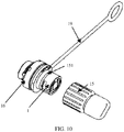
FIG. 10 is a schematic structural exploded view of an adapter and a second dust-proof cap according to an embodiment of this application. -
FIG. 1 is a schematic structural diagram of an FTTH network. The FTTH network includes a central office (CO, Central Office) 01, a connectorized fiber distribution point (CFDP, Connectorized Fiber Distribution Point) 03, and a customer splicing point (CSP, Customer Splicing Point) 05. Thecentral office 01 is connected to the connectorizedfiber distribution point 03 by using anoptical distribution cable 02. The connectorizedfiber distribution point 03 is connected to thecustomer splicing point 05 by using anoptical drop cable 04. An optical fiber connector provided in the embodiments of this application is applicable to a connection between theoptical drop cable 04 and the connectorizedfiber distribution point 03. It should be noted that this application is described by using the FTTH network as an example. The solution in this application may also be used in other types of optical communications networks. - According to a first aspect, as shown in
FIG. 2 , an embodiment of this application provides an optical fiber connector, including anadapter 1, anoptical fiber sub-assembly 2, anoptical fiber sub-assembly 3, and anoptical cable 4. A structure of theoptical fiber sub-assembly 2 is shown inFIG. 3 and FIG. 4 . Theoptical fiber sub-assembly 2 includes aconnector component 21. A first end of theconnector component 21 is used to connect theoptical cable 4. Aferrule 211 is disposed at a second end of theconnector component 21. Aprotection tube 212 is disposed around theferrule 211. An end surface of theferrule 211 protrudes from an end surface of theprotection tube 212 or an end surface of theferrule 211 is level with an end surface of theprotection tube 212. A structure of theadapter 1 is shown inFIG. 6 , ajack 11 and anannular slot 12 around thejack 11 are disposed at a first end of theadapter 1. A second end of theadapter 1 is used to insert theoptical fiber sub-assembly 3. When theoptical fiber sub-assembly 2 and theadapter 1 are interconnected, theferrule 211 of theoptical fiber sub-assembly 2 is inserted into thejack 11 of theadapter 1, and theprotection tube 212 of theoptical fiber sub-assembly 2 is correspondingly inserted into theannular slot 12. - For the optical fiber connector provided in this embodiment of this application, the end surface of the
ferrule 211 protrudes from the end surface of theprotection tube 212 or the end surface of theferrule 211 is level with the end surface of theprotection tube 212 in theoptical fiber sub-assembly 2. Therefore, during connection of theoptical fiber sub-assembly 2 and theadapter 1, a position of theferrule 211 is visible to an operator, to help align theferrule 211 with thejack 11 of theadapter 1. As a result, an insertion success rate is higher. theferrule 211 is protected from repeated impact due to incorrect insertion, and theferrule 211 is protected from damages. In addition, during routine use of theoptical fiber sub-assembly 2, theferrule 211 needs to be regularly or irregularly cleaned. The end surface of theferrule 211 protrudes from the end surface of theprotection tube 212 or the end surface of theferrule 211 is level with the end surface of theprotection tube 212, thereby further facilitating an operation of cleaning theferrule 211. - In a possible implementation, a height difference H between the end surface of the
ferrule 211 and the end surface of theprotection tube 212 may be between 0 mm and 0.5 mm. The height difference H within the foregoing range helps an operator to see the position of theferrule 211, and also helps protect the ferrule effectively. - To effectively protect a connection part between the
optical fiber sub-assembly 2 and theadapter 1 to meet the IP68 protection level, as shown inFIG. 3, FIG. 4 , andFIG. 5 , a lockingcap 22 may be sleeved over theconnector component 21. After theoptical fiber sub-assembly 2 is inserted into theadapter 1, the lockingcap 22 is connected to theadapter 1, so that the lockingcap 22 is tightly wrapped around a connection position of theoptical fiber sub-assembly 2 and theadapter 1, so that the optical fiber connector is protected from damages caused by an external environment. - The locking
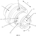
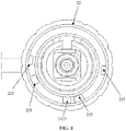
cap 22 and theadapter 1 may be connected in various manners. For example, the lockingcap 22 and theadapter 1 may be connected through thread join. However, a thread connection manner requires repeated rotations for tightening and untightening, resulting in a troublesome and time-consuming operation. Moreover, thread tightening force that operators apply may be different, resulting in different tightening effects. In addition, long-time vibration may loosen the thread connection, to affect long-term reliability of aferrule connecting member 213. Therefore, the lockingcap 22 may be clamped at theadapter 1 by using a clamp structure. Specifically, as shown inFIG. 6 andFIG. 7 , arotation locking slot 13 is provided in a side wall of theadapter 1. Therotation locking slot 13 includes anaxial section 131 extending in an axial direction X and acircumferential section 132 extending in a circumferential direction Y. An opening is formed at an outer end of theaxial section 131, an inner end of theaxial section 131 is in communication with thecircumferential section 132, and an extendingportion 133 extending towards the first end of theadapter 1 is formed at one end of thecircumferential section 132. The lockingcap 22 can rotate with respect to theconnector component 21. As shown inFIG. 8 , a connectingkey 221 is disposed on a wall of an inner hole of the lockingcap 22. As shown inFIG. 4 andFIG. 5 , aspring 23 is disposed between theconnector component 21 and the lockingcap 22. When theoptical fiber sub-assembly 2 is inserted into theadapter 1 in the axial direction X, the lockingcap 22 is sheathed over theadapter 1, and the connectingkey 221 enters theaxial section 131 from the opening at the outer end of theaxial section 131. When the connectingkey 221 is at the inner end of theaxial section 131, rotating the lockingcap 22 enables the connecting key 221 to enter the end of thecircumferential section 132. In this case, an elastic force of thespring 23 may enable the lockingcap 22 to move away from theadapter 1, so that the connectingkey 221 is clamped at the extendingportion 133 of the end of thecircumferential section 132, to prevent the connecting key 221 from moving in a circumferential direction, and prevent thelocking cap 22 from coming off theadapter 1. - In the foregoing embodiment, because the locking
cap 22 is sleeved over theconnector component 21, and the lockingcap 22 is clamped at therotation locking slot 13 by using the connectingkey 221. During assembly of theoptical fiber sub-assembly 2 and theadapter 1, after theferrule 211 is inserted into thejack 11 of theadapter 1, the connecting key 221 merely needs to be rotated into anend extension portion 133 of therotation locking slot 13, time-saving and labor-saving due to no repeated rotation. Moreover, because thespring 23 is disposed between theconnector component 21 and the lockingcap 22, under the elastic force of thespring 23, the connecting key 221 can be tightly clamped at theend extension portion 133 of therotation locking slot 13. In this way, theoptical fiber sub-assembly 2 and theadapter 1 do not get loosened even under long-time vibration, ensuring long-term reliability of the optical fiber connector. - As shown in
FIG. 8 , there may be two connectingkeys 221; correspondingly, there may be tworotation locking slots 13. The two connectingkeys 221 and the tworotation locking slots 13 are clamped in a one-to-one correspondence manner. In this way, a locking force can be distributed more uniformly, to prevent theoptical fiber sub-assembly 2 from coming off theadapter 1. As allowed by an arrangement space, there may be more than two connectingkeys 221 and more than tworotation locking slots 13. For example, there are three or four connectingkeys 221, and there are three or fourrotation locking slots 13. This is not limited herein. - To prevent the
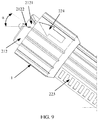
connector component 21 from rotating with respect to theadapter 1, as shown inFIG. 9 , anotch 2121 may be provided in theprotection tube 212, to make the protection tube 212 a non-closed structure. Correspondingly, as shown inFIG. 6 , a separatingrib 121 may be formed at a position, corresponding to thenotch 2121, in theannular slot 12. When theprotection tube 212 is inserted into theannular slot 12, the separatingrib 121 is correspondingly inserted into thenotch 2121. In this way, the separatingrib 121 may prevent theprotection tube 212 from rotating, to prevent theconnector component 21 from rotating with respect to theadapter 1. - As shown in
FIG. 9 , to help align the separatingrib 121 with thenotch 2121, abeveled edge 2122 may be formed at an outer end of thenotch 2121, so that thenotch 2121 forms a shape of a horn flare. In this way, even if the separatingrib 121 is not aligned with the center of thenotch 2121, the separatingrib 121 can be guided by thebeveled edge 2122 to slide into thenotch 2121. When an operator connects theadapter 1 to theoptical fiber sub-assembly 2, visibility of the position of theferrule 211 helps align theferrule 211 with thejack 11. In addition, a guiding effect of thebeveled edge 2122 may enable thenotch 2121 of theprotection tube 212 to be aligned with the separatingrib 121, thereby further improving insertion efficiency and an insertion success rate, and effectively protecting a plug from damages. - Specifically, as shown in
FIG. 9 , thebeveled edge 2122 may be a chamfered edge. A structure of the chamfered edge is more convenient for processing. An opening at an outer end of the horn flare may be set to be relatively large, to have a relatively large guiding range. As shown inFIG. 9 , an inclination angle α of a single-sided beveled edge 2122 may be set to be greater than or equal to 0° and less than or equal to 30°. For example, the inclination angle α of the single-sided beveled edge 2122 may be set to 10°, 12°, 15°, 30°, or the like. The angle of α may be adjusted according to an actual requirement. This is not limited herein. In addition, thebeveled edge 2122 may be a filleted edge. The filleted edge has a smoother surface without a sharp side, so that the separating rib can be protected from wear. - Specifically, as shown in
FIG. 4 andFIG. 5 , theconnector component 21 includes theferrule connecting member 213, a connectingshaft 214, and an opticalcable fixing apparatus 215. Theferrule 211 is disposed at one end of theferrule connecting member 213. The other end of theferrule connecting member 213 is connected to the connectingshaft 214. The connectingshaft 214 and theferrule connecting member 213 may be connected through a thread. One end, away from theferrule connecting member 213, of the connectingshaft 214 is connected to the opticalcable fixing apparatus 215. The opticalcable fixing apparatus 215 is used to fix theoptical cable 4. A throughhole 2141 extending in an axial direction is provided in the connectingshaft 214. The throughhole 2141 is used for a cable core of theoptical cable 4 to pass through. The cable core passing through the through hole is connected to theferrule 211. As shown inFIG. 7 , aceramic tube 111 is disposed in thejack 11 of theadapter 1. When theoptical fiber sub-assembly 2 and theadapter 1 are interconnected, theferrule connecting member 213 fits thejack 11, and theferrule 211 fits theceramic tube 111. - A disposition position of the
spring 23 may be shown inFIG. 4 . The lockingcap 22 is sleeved over the connectingshaft 214, anaxial shoulder 2142 is formed on an outer wall of the connectingshaft 214, aboss 222 is formed on an inner wall of the lockingcap 22, one end of thespring 23 abuts against theaxial shoulder 2142, and the other end of thespring 23 abuts against theboss 222. In this case, when the lockingcap 22 is pushed towards theadapter 1, thespring 23 is compressed. When the connectingkey 221 is located at the end of thecircumferential section 132, the lockingcap 22 is released, and the lockingcap 22 may move away from theadapter 1 under a restoring force of thespring 23, to enable the connecting key 221 to be clamped at the extendingportion 133 at one end of thecircumferential section 132. In this case, the connectingkey 221 is in a tightly compressed state for a long time under the elastic force of the spring. In the structure, thespring 23 may be positioned and installed without using an additional component, so that an assembly operation is convenient. - To facilitate holding when the locking
cap 22 is operated to rotate, as shown inFIG. 9 , symmetrical flattenedplanes 223 may be formed on side walls of the lockingcap 22. In this way, when the lockingcap 22 is operated to rotate, the two flattenedplanes 223 may be held to perform a rotation operation, to prevent slips. To further increase friction, anti-slip grooves may be further formed on the flattenedplane 223, and the hand feel can be improved during operation. It should be noted that there may be a plurality of pairs, for example, two or three pairs of symmetrical flattenedplanes 223. This is not limited herein. - As shown in
FIG. 4 andFIG. 5 , the opticalcable fixing apparatus 215 includes arear retainer 2151, aheat shrink tubing 2152, and a crimpingstructure 2153, theheat shrink tubing 2152 is sleeved over theoptical cable 4, and the crimpingstructure 2153 is used to rivet an aramid yarn layer of theoptical cable 4 and the connectingshaft 214 together, to increase tensile strength of theoptical fiber sub-assembly 2. Therear retainer 2151 is sleeved over theheat shrink tubing 2152 and is connected to the end, away from theferrule connecting member 213, of the connectingshaft 214. In this way, theoptical cable 4 at a tail end of theoptical fiber sub-assembly 2 may be effectively fixed. Therear retainer 2151 may be first fabricated and eventually sleeved, or may be eventually cast in an overall injection molding manner, to further increase tensile strength and sealing performance of theoptical fiber sub-assembly 2. To limit therear retainer 2151, a locating slot may be provided in a side wall of the connectingshaft 214, asnap ring 2154 is disposed in the locating slot, and therear retainer 2151 is clamped to thesnap ring 2154. In this way, therear retainer 2151 can be prevented from moving in an axial direction. - During connection of the
optical fiber sub-assembly 2 and theadapter 1, thenotch 2121 of theprotection tube 212 needs to be aligned with the separatingrib 121 of theannular slot 12, and the connecting key 221 on the lockingcap 22 needs to be aligned with the opening of therotation locking slot 13 on theadapter 1. Relative positions of the separatingrib 121 on theadapter 1 and the opening of therotation locking slot 13 are fixed, and the lockingcap 22 may rotate with respect to theconnector component 21. Therefore, the relative positions of thenotch 2121 of theprotection tube 212 and the connecting key 221 on the lockingcap 22 are not fixed. To facilitate an alignment operation, as shown inFIG. 9 , anindication mark 224 may be disposed on an outer wall of the lockingcap 22. Theindication mark 224 may be an arrow, an indication line or the like. A position of theindication mark 224 may be set, so that when theindication mark 224 is aligned with thenotch 2121 of theprotection tube 212, the relative positions of thenotch 2121 of theprotection tube 212 and the connecting key 221 on the lockingcap 22 adapt to the relative positions of the separatingrib 121 on theadapter 1 and the opening of therotation locking slot 13. In this case, it is only necessary to align thenotch 2121 of theprotection tube 212 with the separatingrib 121 of theannular slot 12, and accordingly the connecting key 221 on the lockingcap 22 is naturally aligned with the opening of therotation locking slot 13 on theadapter 1. - Correspondingly, to conveniently indicate whether the
optical fiber sub-assembly 2 and theadapter 1 are in a locked state or a loose state, as shown inFIG. 6 , astate indication symbol 14 may be disposed on theadapter 1. Thestate indication symbol 14 may include a symbol "0" and a symbol "1". The symbol "0" represents that theoptical fiber sub-assembly 2 and theadapter 1 are in a loose state. The symbol" 1" represents that theoptical fiber sub-assembly 2 and theadapter 1 are in a locked state. In this way, when theindication mark 224 on the lockingcap 22 points at the symbol "0", the connectingkey 221 is at a starting end of thecircumferential section 132 of therotation locking slot 13, theoptical fiber sub-assembly 2 and theadapter 1 are in a loose state, and theoptical fiber sub-assembly 2 and theadapter 1 may move in the axial direction X to separate. When theindication mark 224 on the lockingcap 22 points at the symbol "1", the connectingkey 221 is at theend extension portion 133 of thecircumferential section 132 of therotation locking slot 13, theoptical fiber sub-assembly 2 and theadapter 1 are in a locked state, and theoptical fiber sub-assembly 2 and theadapter 1 cannot move in the axial direction X to separate. - To prevent the
indication mark 224 from deviating far away from thenotch 2121 of theprotection tube 212 when the lockingcap 22 rotates, a rotation-limiting structure may be disposed between the lockingcap 22 and theprotection tube 212. The rotation-limiting structure is used to limit a rotation angle of the lockingcap 22 with respect to theconnector component 21, so that the rotation angle of the lockingcap 22 adapts to a rotation angle required for the connecting key 221 to be rotated into one end of therotation locking slot 13 from the opening of therotation locking slot 13. Specifically, as shown inFIG. 8 , the rotation-limiting structure includes two first limitingbumps 225 disposed at an interval on the inner wall of the lockingcap 22 and a second limitingbump 2123 disposed on theprotection tube 212. The second limitingbump 2123 is located between the two first limiting bumps 225. In this way, the rotation angle of the lockingcap 22 may be restricted in a relatively small range, so that theindication mark 224 does not deviate far away from thenotch 2121 of theprotection tube 212, to facilitate an alignment operation. - To prevent external foreign objects such as moisture and dust from entering the optical fiber connector, as shown in
FIG. 4 andFIG. 5 , a sealingring 216 may be disposed at a connection between the lockingcap 22 and the connectingshaft 214, to prevent foreign objects such as moisture and dust from entering the optical fiber connector through the connection between the lockingcap 22 and the connectingshaft 214 and then reaching IP68 protection level. - The second end of the
connector component 21 and the first end of theadapter 1 are in an open state before being connected. In this case, to prevent foreign objects such as dust from entering theconnector component 21 and theadapter 1, as shown inFIG. 3 andFIG. 5 , a first dust-proof cap 24 may be detachably connected at the second end of theconnector component 21. To prevent the first dust-proof cap 24 from missing, the first dust-proof cap 24 may be connected to therear retainer 2151 through astring 241. To enable the first dust-proof cap 24 to form a desirable sealing effect when the first dust-proof cap 24 is closed, a sealingring 242 may be disposed between the first dust-proof cap 24 and the lockingcap 22. In this way, before theoptical fiber sub-assembly 2 is inserted into theadapter 1, dustproofness and waterproofness can be provided, and theferrule 211 can be protected. As shown inFIG. 7 , a second dust-proof cap 15 is detachably connected to the first end of theadapter 1. In this way, before theoptical fiber sub-assembly 2 is inserted into theadapter 1, dustproofness and waterproofness can be provided, and theceramic tube 111 in theadapter 1 can be protected. When theadapter 1 and theoptical fiber sub-assembly 2 need to be connected, it is only necessary to detach the first dust-proof cap 24 and the second dust-proof cap 15. As shown inFIG. 10 , to enable the second dust-proof cap 15 to form a desirable sealing effect when being closed, a sealingring 151 is further disposed on theadapter 1. - Because the
adapter 1 is usually installed on a housing wall of a device, as shown inFIG. 7 , anut 16 is connected at the second end of theadapter 1 through a thread, aflange 17 is disposed on the side wall of theadapter 1, asealing pad 18 is disposed between theflange 17 and thenut 16. During assembly of theadapter 1, thenut 16 may be first detached, the second end of theadapter 1 is then passed through an assembly hole in the housing wall of the device, and thenut 16 is eventually screwed into the second end of theadapter 1 from the other side of the housing wall of the device. In this case, thesealing pad 18 is located between theflange 17 and the housing wall of the device to seal the assembly hole in the housing wall. To prevent the second dust-proof cap 15 from missing, as shown inFIG. 7 , thesealing pad 18 may be connected to the second dust-proof cap 15 through astring 19, where thesealing pad 18, the second dust-proof cap 15, and thestring 19 may be integrally made of the same material (for example, a rubber material). - According to a second aspect, an embodiment of this application further provides an optical fiber sub-assembly. For related technical features thereof, refer to the description of features related to the optical fiber sub-assembly in the foregoing optical fiber connector embodiment. Details are not described herein again.
- According to a third aspect, an embodiment of this application further provides an adapter. For related technical features thereof, refer to the description of features related to the adapter in the foregoing optical fiber connector embodiment. Details are not described herein again.
- In the descriptions of this specification, the described specific features, structures, materials, or characteristics may be combined in a proper manner in any one or more of the embodiments or examples.
- The foregoing descriptions are merely specific implementations of the present invention, but are not intended to limit the protection scope of the present invention. Any variation or replacement readily figured out by a person skilled in the art within the technical scope disclosed in the present invention shall fall within the protection scope of the present invention. Therefore, the protection scope of the present invention shall be subject to the protection scope of the claims.
Claims (17)
- An optical fiber sub-assembly, comprising a connector component, wherein a first end of the connector component is used to connect an optical cable, a ferrule is disposed at a second end of the connector component, a protection tube is disposed around the ferrule, and an end surface of the ferrule protrudes from an end surface of the protection tube or an end surface of the ferrule is level with an end surface of the protection tube.
- The optical fiber sub-assembly according to claim 1, wherein a locking cap is sleeved over the connector component, a connecting key is disposed on a wall of an inner hole of the locking cap, the locking cap is able to rotate with respect to the connector component, and a spring is disposed between the connector component and the locking cap.
- The optical fiber sub-assembly according to claim 2, wherein the connector component comprises a ferrule connecting member, a connecting shaft, and an optical cable fixing apparatus, the ferrule is disposed at one end of the ferrule connecting member, the other end of the ferrule connecting member is connected to the connecting shaft, one end, away from the ferrule connecting member, of the connecting shaft is connected to the optical cable fixing apparatus, the optical cable fixing apparatus is used to fix the optical cable, a through hole extending in an axial direction is provided in the connecting shaft, the through hole is used for a cable core of the optical cable to pass through, and the cable core passes through the through hole to be connected to the ferrule at the ferrule connecting member.
- The optical fiber sub-assembly according to claim 3, wherein the locking cap is sleeved over the connecting shaft, an axial shoulder is formed on an outer wall of the connecting shaft, a boss is formed on an inner wall of the locking cap, one end of the spring abuts against the axial shoulder, and the other end of the spring abuts against the boss.
- The optical fiber sub-assembly according to claim 3 or 4, wherein a sealing ring is disposed between the locking cap and the connecting shaft.
- The optical fiber sub-assembly according to any one of claims 3 to 5, wherein the optical cable fixing apparatus comprises a rear retainer, a heat shrink tubing, and a crimping structure, the heat shrink tubing is sleeved over the optical cable, the crimping structure is used to rivet an aramid yarn layer of the optical cable and the connecting shaft together, and the rear retainer is sleeved over the heat shrink tubing and is connected to the end, away from the ferrule connecting member, of the connecting shaft.
- The optical fiber sub-assembly according to claim 6, wherein a locating slot is provided in a side wall of the connecting shaft, a snap ring is disposed in the locating slot, and the rear retainer is clamped to the snap ring.
- The optical fiber sub-assembly according to any one of claims 1 to 7, wherein a first dust-proof cap is detachably connected to the second end of the connector component.
- The optical fiber sub-assembly according to any one of claims 1 to 8, wherein the protection tube has a notch.
- The optical fiber sub-assembly according to claim 9, wherein a beveled edge is formed at an outer end of the notch.
- An optical fiber connector, comprising:an adapter, wherein a jack and an annular slot provided around the jack are disposed at a first end of the adapter; andan optical fiber sub-assembly, wherein the optical fiber sub-assembly is the optical fiber sub-assembly according to any one of claims 1 to 10, whereina ferrule of the optical fiber sub-assembly is inserted into the jack of the adapter, and a protection tube of the optical fiber sub-assembly is correspondingly inserted into the annular slot.
- The optical fiber connector according to claim 11, wherein a locking cap is sleeved over the connector component, and the locking cap is clamped at the adapter.
- The optical fiber connector according to claim 12, wherein the locking cap is able to rotate with respect to the connector component, a connecting key is disposed on a wall of an inner hole of the locking cap, a spring is disposed between the connector component and the locking cap, a rotation locking slot is provided in a side wall of the adapter, the rotation locking slot comprises an axial section extending in an axial direction and a circumferential section extending in a circumferential direction, an opening is formed at an outer end of the axial section, an inner end of the axial section is in communication with the circumferential section, an extending portion extending towards the first end of the adapter is formed at an inner end of the circumferential section, the locking cap is sheathed over the adapter, the connecting key is clamped in the extending portion, and an elastic force of the spring can prevent the connecting key from coming off the extending portion.
- The optical fiber connector according to claim 13, wherein there are a plurality of connecting keys, there are a plurality of rotation locking slots, and the plurality of connecting keys and the plurality of rotation locking slots are clamped in a one-to-one correspondence manner.
- The optical fiber connector according to any one of claims 11 to 14, wherein the protection tube has a notch, a separating rib is formed at a position, corresponding to the notch, in the annular slot, and when the protection tube is inserted into the annular slot, the separating rib is correspondingly inserted into the notch.
- The optical fiber connector according to claim 15, wherein a beveled edge is formed at an outer end of the notch.
- The optical fiber connector according to any one of claims 11 to 16, wherein a second dust-proof cap is detachably connected to the first end of the adapter, a nut is connected at a second end of the adapter through a thread, a flange is disposed on the side wall of the adapter, a sealing ring is disposed between the flange and the nut, and the sealing ring is connected to the second dust-proof cap through a string.
Priority Applications (1)
| Application Number | Priority Date | Filing Date | Title |
|---|---|---|---|
| EP22196398.6A EP4187294A1 (en) | 2018-09-03 | 2019-09-03 | Optical fiber sub-assembly and optical fiber connector |
Applications Claiming Priority (2)
| Application Number | Priority Date | Filing Date | Title |
|---|---|---|---|
| CN201811028827.8A CN109188611B (en) | 2018-09-03 | 2018-09-03 | Optical fiber connector and optical fiber connector |
| PCT/CN2019/104255 WO2020048464A1 (en) | 2018-09-03 | 2019-09-03 | Optic fiber connecting head and optic fiber connector |
Related Child Applications (1)
| Application Number | Title | Priority Date | Filing Date |
|---|---|---|---|
| EP22196398.6A Division EP4187294A1 (en) | 2018-09-03 | 2019-09-03 | Optical fiber sub-assembly and optical fiber connector |
Publications (2)
| Publication Number | Publication Date |
|---|---|
| EP3726265A1 true EP3726265A1 (en) | 2020-10-21 |
| EP3726265A4 EP3726265A4 (en) | 2021-01-27 |
Family
ID=64914656
Family Applications (2)
| Application Number | Title | Priority Date | Filing Date |
|---|---|---|---|
| EP19857250.5A Ceased EP3726265A4 (en) | 2018-09-03 | 2019-09-03 | Optic fiber connecting head and optic fiber connector |
| EP22196398.6A Pending EP4187294A1 (en) | 2018-09-03 | 2019-09-03 | Optical fiber sub-assembly and optical fiber connector |
Family Applications After (1)
| Application Number | Title | Priority Date | Filing Date |
|---|---|---|---|
| EP22196398.6A Pending EP4187294A1 (en) | 2018-09-03 | 2019-09-03 | Optical fiber sub-assembly and optical fiber connector |
Country Status (13)
| Country | Link |
|---|---|
| US (1) | US11378758B2 (en) |
| EP (2) | EP3726265A4 (en) |
| JP (2) | JP2021513115A (en) |
| CN (2) | CN110596823B (en) |
| AR (1) | AR122433A1 (en) |
| CL (1) | CL2020001866A1 (en) |
| CO (1) | CO2020009221A2 (en) |
| MX (1) | MX2020007589A (en) |
| MY (1) | MY198448A (en) |
| PE (1) | PE20212009A1 (en) |
| PH (1) | PH12020551053A1 (en) |
| PY (1) | PY1973220A (en) |
| WO (1) | WO2020048464A1 (en) |
Families Citing this family (39)
| Publication number | Priority date | Publication date | Assignee | Title |
|---|---|---|---|---|
| CN110596823B (en) * | 2018-09-03 | 2020-12-04 | 华为技术有限公司 | Optical fiber connector and optical fiber connector |
| US11557884B2 (en) | 2019-05-30 | 2023-01-17 | International Business Machines Corporation | Fixture aligner |
| CN110542952B (en) | 2019-07-26 | 2021-05-18 | 华为技术有限公司 | Optical fiber connector and optical fiber connector |
| US10845542B1 (en) | 2019-08-19 | 2020-11-24 | Afl Telecommunications Llc | Cable node transition assemblies |
| CN110554467B (en) * | 2019-09-18 | 2024-11-05 | 沈阳兴华航空电器有限责任公司 | A detachable optical fiber contact body |
| CN120370478A (en) * | 2019-10-28 | 2025-07-25 | 华为技术有限公司 | Pre-connector, optical cable assembly and communication equipment |
| CN110749962A (en) * | 2019-12-06 | 2020-02-04 | 惠州市永恒通宽带器材有限公司 | A waterproof and dustproof adapter, connector and connector assembly |
| US12210196B2 (en) * | 2019-12-13 | 2025-01-28 | Us Conec Ltd. | Cover for a fiber optic ferrule and ferrule push |
| CN111061017B (en) * | 2019-12-31 | 2020-12-01 | 烽火通信科技股份有限公司 | A connector and optical fiber connection assembly |
| CN111308615B (en) * | 2020-02-19 | 2021-10-01 | 华为技术有限公司 | Fiber Optic Connector Plugs, Fiber Optic Adapters and Fiber Optic Connectors |
| CN113495326B (en) * | 2020-04-02 | 2025-12-30 | 中兴通讯股份有限公司 | Fiber optic cable assemblies and fiber optic cable connection equipment |
| CN111463627B (en) * | 2020-04-07 | 2025-06-24 | 深圳核心医疗科技股份有限公司 | Connection structure and wire pulling device |
| CN111367032A (en) * | 2020-06-01 | 2020-07-03 | 苏州长光华芯光电技术有限公司 | Optical fiber coupling device and laser coupling equipment |
| CN119986919A (en) * | 2020-09-09 | 2025-05-13 | 烽火通信科技股份有限公司 | Connector and optical fiber connection assembly |
| CN112099157B (en) * | 2020-09-22 | 2022-04-15 | 烽火通信科技股份有限公司 | Multi-core optical fiber connector, multi-core optical fiber adapter and multi-core optical fiber connecting assembly |
| CN112158418A (en) * | 2020-09-22 | 2021-01-01 | 信远德怡医疗科技(北京)有限公司 | Consumable bearing device |
| CN112859253B (en) * | 2021-01-25 | 2022-05-31 | 华为技术有限公司 | Optical fiber connector, optical fiber connecting system and box body |
| CN112864788A (en) * | 2021-03-17 | 2021-05-28 | 深圳技术大学 | SESAM packaging structure |
| CN112946831B (en) * | 2021-04-09 | 2024-11-15 | 广东亿源通科技股份有限公司 | A connection structure between an adapter and a connector |
| CN112946846A (en) * | 2021-04-23 | 2021-06-11 | 杭州雷特通信技术有限公司 | Bare fiber module structure and melting-free connector and unit assembly |
| CN113189720B (en) * | 2021-04-29 | 2022-08-30 | 武汉光迅科技股份有限公司 | Active optical cable assembly and assembling method thereof |
| CN113009643B (en) * | 2021-05-26 | 2021-08-20 | 中天宽带技术有限公司 | Prefabricated connector, coupler and prefabricated connector assembly |
| CN113568110B (en) * | 2021-07-08 | 2023-01-31 | 烽火通信科技股份有限公司 | Outdoor preformed optical fiber connector and adapter assembly |
| CN113640921B (en) * | 2021-09-09 | 2025-01-28 | 惠州市飞博康实业有限公司 | A composite outdoor connector |
| CN114063220B (en) * | 2021-11-19 | 2023-03-24 | 杭州润州光电技术有限公司 | Optical fiber connector, optical fiber adapter and optical fiber connector |
| CN114019616B (en) * | 2021-12-14 | 2025-07-25 | 杭州润州光电技术有限公司 | Optical fiber connector and optical fiber connection assembly thereof |
| CN114518622B (en) * | 2022-02-16 | 2023-01-31 | 烽火通信科技股份有限公司 | Adapter, protection box and connector assembly of high-speed joint |
| CN115016070B (en) * | 2022-06-22 | 2023-08-08 | 南京华脉科技股份有限公司 | Optical fiber connector and adapter for realizing fast assembly |
| CN115047569B (en) * | 2022-07-13 | 2023-09-26 | 武汉光迅科技股份有限公司 | Optical fiber connector and assembly method thereof |
| CN115444370B (en) * | 2022-09-21 | 2025-12-23 | 上海元景联医疗科技有限公司 | OCT catheter loading system |
| CN115437080B (en) * | 2022-10-08 | 2023-08-18 | 江苏亨通光电股份有限公司 | Optical cable node connecting device |
| CN116643358A (en) * | 2023-01-05 | 2023-08-25 | 浙江超前通信科技股份有限公司 | A kind of MPO fiber optic connector |
| CN116243430A (en) * | 2023-02-20 | 2023-06-09 | 中航光电科技股份有限公司 | A circular connector anti-loosening structure |
| CN115840271B (en) * | 2023-02-21 | 2023-05-12 | 中天宽带技术有限公司 | Connector convenient for field assembly |
| EP4681006A1 (en) * | 2023-03-16 | 2026-01-21 | CommScope Technologies LLC | Fiber optic connector with boot or coupler that is removeable and/or mountable after affixation of the fiber optic connector to a cable |
| CN116643359B (en) * | 2023-06-12 | 2024-03-22 | 东莞市一振通讯科技有限公司 | An optical fiber docking device including an optical fiber adapter and an optical fiber connector |
| CN117310894B (en) * | 2023-11-29 | 2024-03-08 | 厦门唯恩电气有限公司 | A watertight optical fiber connector plug and a watertight optical fiber connector |
| CN117518367A (en) * | 2023-12-13 | 2024-02-06 | 杨帆 | An optical fiber connector component |
| CN118315908B (en) * | 2024-06-13 | 2024-08-16 | 长鹰恒容电磁科技(成都)有限公司 | A passively mode-locked fiber laser with multistate solitons |
Family Cites Families (26)
| Publication number | Priority date | Publication date | Assignee | Title |
|---|---|---|---|---|
| AU577099B2 (en) * | 1984-03-19 | 1988-09-15 | E.I. Du Pont De Nemours And Company | Receptacle, plug and optical connector |
| US5478970A (en) * | 1994-02-03 | 1995-12-26 | D. G. O'brien, Inc. | Apparatus for terminating and interconnecting rigid electrical cable and method |
| JP3066739B2 (en) * | 1996-07-15 | 2000-07-17 | セイコーインスツルメンツ株式会社 | General-purpose optical connector and basic plug |
| KR19980016218A (en) * | 1996-08-27 | 1998-05-25 | 양승택 | Multi-fiber connector |
| US5732175A (en) * | 1997-01-31 | 1998-03-24 | Litecom, Inc. | Connecting system for fiber optic termination |
| US7467896B2 (en) * | 2000-05-26 | 2008-12-23 | Corning Cable Systems Llc | Fiber optic drop cables and preconnectorized assemblies |
| JP2002107570A (en) | 2000-07-24 | 2002-04-10 | Auto Network Gijutsu Kenkyusho:Kk | Optical connector |
| JP2002156558A (en) * | 2000-11-17 | 2002-05-31 | Auto Network Gijutsu Kenkyusho:Kk | Optical connector device |
| CN201017071Y (en) * | 2006-12-22 | 2008-02-06 | 深圳市恒捷丰光电科技有限公司 | Flexible metal sleeve optical fiber jumper wire |
| US7708469B2 (en) * | 2008-04-11 | 2010-05-04 | Corning Cable Systems Llc | Fiber optic connector assembly and method for venting gas inside a fiber optic connector sub-assembly |
| AR071489A1 (en) * | 2008-04-21 | 2010-06-23 | Adc Telecommunications Inc | CONNECTED OPTICAL FIBER CONNECTOR WITH BODY CONNECTED TO A CYLINDRICAL CABLE FOR A UNIT WRAP |
| EP2525245A4 (en) * | 2010-01-14 | 2017-01-04 | Fujikura, Ltd. | Optical connector, assembly method for optical connector, reinforcement method for fusion-spliced section, pin clamp, optical connector having cap, cap for optical connector, assembly tools for optical connector and optical connector assembly set |
| US8870469B2 (en) * | 2010-05-12 | 2014-10-28 | Adc Telecommunications, Inc. | Fiber optic connector and method of applying same to a fiber optic cable |
| HUE031727T2 (en) * | 2012-06-26 | 2017-07-28 | Huawei Tech Co Ltd | Fiber optic connector, fiber optic adapter and fiber optic connector |
| CN103840274A (en) * | 2012-11-21 | 2014-06-04 | 陈幼萍 | Coaxial cable connector capable of being repeatedly used |
| KR101912411B1 (en) * | 2013-11-12 | 2018-10-26 | 후아웨이 테크놀러지 컴퍼니 리미티드 | Optical fibre joint, optical fibre adaptor and optical fibre connector |
| EP3177952B1 (en) * | 2014-08-06 | 2020-11-18 | Prysmian S.p.A. | Optical fiber connector assembly |
| DK3177953T3 (en) * | 2014-08-06 | 2020-12-21 | Prysmian Spa | Optical fiber for connector device |
| AU2014415442B2 (en) | 2014-12-25 | 2018-06-14 | Huawei Technologies Co., Ltd. | Connecting member and optical fibre connector |
| JP2018040820A (en) * | 2015-02-23 | 2018-03-15 | Seiオプティフロンティア株式会社 | Optical connector plug, optical connector receptacle, and optical connector connection structure |
| EP3098634A1 (en) * | 2015-05-29 | 2016-11-30 | Corning Optical Communications LLC | Cap apparatuses for sealing optical fiber connectors and associated methods |
| EP3495862A4 (en) | 2016-08-02 | 2020-03-25 | Sumitomo Electric Industries, Ltd. | OPTICAL CONNECTOR |
| MX2019003561A (en) | 2016-09-30 | 2020-01-21 | Huawei Tech Co Ltd | Optical fiber sub-assembly, optical fiber adapter, and optical fiber connector. |
| CN207096505U (en) * | 2017-08-22 | 2018-03-13 | 常州太平通讯科技有限公司 | The miniature jumping fiber joints of optical fibre |
| CN108490551B (en) * | 2017-11-14 | 2020-12-01 | 烽火通信科技股份有限公司 | An optical fiber connector, an optical fiber connector base and an optical fiber connector assembly |
| CN110596823B (en) * | 2018-09-03 | 2020-12-04 | 华为技术有限公司 | Optical fiber connector and optical fiber connector |
-
2018
- 2018-09-03 CN CN201910852585.2A patent/CN110596823B/en active Active
- 2018-09-03 CN CN201811028827.8A patent/CN109188611B/en active Active
-
2019
- 2019-09-03 PY PY201901973220A patent/PY1973220A/en unknown
- 2019-09-03 PE PE2020000964A patent/PE20212009A1/en unknown
- 2019-09-03 EP EP19857250.5A patent/EP3726265A4/en not_active Ceased
- 2019-09-03 AR ARP190102507A patent/AR122433A1/en active IP Right Grant
- 2019-09-03 EP EP22196398.6A patent/EP4187294A1/en active Pending
- 2019-09-03 WO PCT/CN2019/104255 patent/WO2020048464A1/en not_active Ceased
- 2019-09-03 MY MYPI2020003547A patent/MY198448A/en unknown
- 2019-09-03 MX MX2020007589A patent/MX2020007589A/en unknown
- 2019-09-03 JP JP2020542646A patent/JP2021513115A/en active Pending
-
2020
- 2020-07-08 PH PH12020551053A patent/PH12020551053A1/en unknown
- 2020-07-14 CL CL2020001866A patent/CL2020001866A1/en unknown
- 2020-07-27 CO CONC2020/0009221A patent/CO2020009221A2/en unknown
- 2020-08-03 US US16/983,102 patent/US11378758B2/en active Active
-
2022
- 2022-12-19 JP JP2022004153U patent/JP3240929U/en active Active
Also Published As
| Publication number | Publication date |
|---|---|
| JP2021513115A (en) | 2021-05-20 |
| CN109188611B (en) | 2020-08-07 |
| CN110596823A (en) | 2019-12-20 |
| US11378758B2 (en) | 2022-07-05 |
| PE20212009A1 (en) | 2021-10-18 |
| MY198448A (en) | 2023-08-29 |
| US20200363593A1 (en) | 2020-11-19 |
| JP3240929U (en) | 2023-02-16 |
| PH12020551053A1 (en) | 2021-08-02 |
| EP4187294A1 (en) | 2023-05-31 |
| MX2020007589A (en) | 2020-09-03 |
| PY1973220A (en) | 2020-03-04 |
| WO2020048464A1 (en) | 2020-03-12 |
| AR122433A1 (en) | 2022-09-14 |
| CN109188611A (en) | 2019-01-11 |
| CL2020001866A1 (en) | 2020-10-02 |
| CN110596823B (en) | 2020-12-04 |
| CO2020009221A2 (en) | 2020-10-30 |
| EP3726265A4 (en) | 2021-01-27 |
Similar Documents
| Publication | Publication Date | Title |
|---|---|---|
| US11378758B2 (en) | Optical fiber sub-assembly and optical fiber connector | |
| JP2021513115A5 (en) | ||
| US10656344B2 (en) | Optical fiber plug, optical fiber adapter, and optical fiber connector assembly | |
| EP3822677B1 (en) | Optical fiber connection head and optical fiber connector | |
| US10649152B1 (en) | Connector system | |
| EP2894501B1 (en) | Optical fibre joint and optical fibre connector | |
| EP3550342B1 (en) | Fiber optic plug | |
| EP2703860B1 (en) | Female hardened optical connectors for use with hybrid receptacle | |
| CN105917259B (en) | A kind of connector and fiber connector | |
| CN212540781U (en) | Direct-insertion sealed optical fiber connector, connector and connector assembly | |
| CN104246563A (en) | Connector for telecommunication enclosures | |
| US11573382B2 (en) | Sealing boots for protecting optical interconnections and related assemblies | |
| US20250314836A1 (en) | Optical fiber connector plug and optical fiber connector | |
| KR101341588B1 (en) | Beanch box for optical fiber micro cable and divergencing set using thereof |
Legal Events
| Date | Code | Title | Description |
|---|---|---|---|
| STAA | Information on the status of an ep patent application or granted ep patent |
Free format text: STATUS: THE INTERNATIONAL PUBLICATION HAS BEEN MADE |
|
| PUAI | Public reference made under article 153(3) epc to a published international application that has entered the european phase |
Free format text: ORIGINAL CODE: 0009012 |
|
| STAA | Information on the status of an ep patent application or granted ep patent |
Free format text: STATUS: REQUEST FOR EXAMINATION WAS MADE |
|
| 17P | Request for examination filed |
Effective date: 20200714 |
|
| AK | Designated contracting states |
Kind code of ref document: A1 Designated state(s): AL AT BE BG CH CY CZ DE DK EE ES FI FR GB GR HR HU IE IS IT LI LT LU LV MC MK MT NL NO PL PT RO RS SE SI SK SM TR |
|
| AX | Request for extension of the european patent |
Extension state: BA ME |
|
| A4 | Supplementary search report drawn up and despatched |
Effective date: 20210114 |
|
| RIC1 | Information provided on ipc code assigned before grant |
Ipc: G02B 6/38 20060101AFI20201223BHEP |
|
| RIN1 | Information on inventor provided before grant (corrected) |
Inventor name: WU, DAN Inventor name: YU, JIANXIONG Inventor name: WU, WENXIN Inventor name: LI, XIUPENG Inventor name: XIONG, WEI |
|
| STAA | Information on the status of an ep patent application or granted ep patent |
Free format text: STATUS: EXAMINATION IS IN PROGRESS |
|
| 17Q | First examination report despatched |
Effective date: 20211103 |
|
| DAV | Request for validation of the european patent (deleted) | ||
| DAX | Request for extension of the european patent (deleted) | ||
| REG | Reference to a national code |
Ref country code: DE Ref legal event code: R003 |
|
| STAA | Information on the status of an ep patent application or granted ep patent |
Free format text: STATUS: THE APPLICATION HAS BEEN REFUSED |
|
| 18R | Application refused |
Effective date: 20221118 |