EP3726198A1 - System and method for monitoring a fire suppression blend - Google Patents
System and method for monitoring a fire suppression blend Download PDFInfo
- Publication number
- EP3726198A1 EP3726198A1 EP19212840.3A EP19212840A EP3726198A1 EP 3726198 A1 EP3726198 A1 EP 3726198A1 EP 19212840 A EP19212840 A EP 19212840A EP 3726198 A1 EP3726198 A1 EP 3726198A1
- Authority
- EP
- European Patent Office
- Prior art keywords
- blend
- fire suppression
- sensors
- gaseous fire
- wavelengths
- Prior art date
- Legal status (The legal status is an assumption and is not a legal conclusion. Google has not performed a legal analysis and makes no representation as to the accuracy of the status listed.)
- Pending
Links
Images

Classifications
-
- G—PHYSICS
- G01—MEASURING; TESTING
- G01N—INVESTIGATING OR ANALYSING MATERIALS BY DETERMINING THEIR CHEMICAL OR PHYSICAL PROPERTIES
- G01N21/00—Investigating or analysing materials by the use of optical means, i.e. using sub-millimetre waves, infrared, visible or ultraviolet light
- G01N21/17—Systems in which incident light is modified in accordance with the properties of the material investigated
- G01N21/25—Colour; Spectral properties, i.e. comparison of effect of material on the light at two or more different wavelengths or wavelength bands
- G01N21/31—Investigating relative effect of material at wavelengths characteristic of specific elements or molecules, e.g. atomic absorption spectrometry
- G01N21/35—Investigating relative effect of material at wavelengths characteristic of specific elements or molecules, e.g. atomic absorption spectrometry using infrared light
- G01N21/3504—Investigating relative effect of material at wavelengths characteristic of specific elements or molecules, e.g. atomic absorption spectrometry using infrared light for analysing gases, e.g. multi-gas analysis
-
- G—PHYSICS
- G01—MEASURING; TESTING
- G01N—INVESTIGATING OR ANALYSING MATERIALS BY DETERMINING THEIR CHEMICAL OR PHYSICAL PROPERTIES
- G01N15/00—Investigating characteristics of particles; Investigating permeability, pore-volume or surface-area of porous materials
- G01N15/06—Investigating concentration of particle suspensions
-
- A—HUMAN NECESSITIES
- A62—LIFE-SAVING; FIRE-FIGHTING
- A62C—FIRE-FIGHTING
- A62C37/00—Control of fire-fighting equipment
- A62C37/50—Testing or indicating devices for determining the state of readiness of the equipment
-
- F—MECHANICAL ENGINEERING; LIGHTING; HEATING; WEAPONS; BLASTING
- F02—COMBUSTION ENGINES; HOT-GAS OR COMBUSTION-PRODUCT ENGINE PLANTS
- F02C—GAS-TURBINE PLANTS; AIR INTAKES FOR JET-PROPULSION PLANTS; CONTROLLING FUEL SUPPLY IN AIR-BREATHING JET-PROPULSION PLANTS
- F02C7/00—Features, components parts, details or accessories, not provided for in, or of interest apart form groups F02C1/00 - F02C6/00; Air intakes for jet-propulsion plants
- F02C7/24—Heat or noise insulation
- F02C7/25—Fire protection or prevention
-
- G—PHYSICS
- G01—MEASURING; TESTING
- G01N—INVESTIGATING OR ANALYSING MATERIALS BY DETERMINING THEIR CHEMICAL OR PHYSICAL PROPERTIES
- G01N21/00—Investigating or analysing materials by the use of optical means, i.e. using sub-millimetre waves, infrared, visible or ultraviolet light
- G01N21/17—Systems in which incident light is modified in accordance with the properties of the material investigated
- G01N21/25—Colour; Spectral properties, i.e. comparison of effect of material on the light at two or more different wavelengths or wavelength bands
- G01N21/31—Investigating relative effect of material at wavelengths characteristic of specific elements or molecules, e.g. atomic absorption spectrometry
- G01N21/33—Investigating relative effect of material at wavelengths characteristic of specific elements or molecules, e.g. atomic absorption spectrometry using ultraviolet light
-
- F—MECHANICAL ENGINEERING; LIGHTING; HEATING; WEAPONS; BLASTING
- F05—INDEXING SCHEMES RELATING TO ENGINES OR PUMPS IN VARIOUS SUBCLASSES OF CLASSES F01-F04
- F05D—INDEXING SCHEME FOR ASPECTS RELATING TO NON-POSITIVE-DISPLACEMENT MACHINES OR ENGINES, GAS-TURBINES OR JET-PROPULSION PLANTS
- F05D2260/00—Function
- F05D2260/80—Diagnostics
-
- G—PHYSICS
- G01—MEASURING; TESTING
- G01N—INVESTIGATING OR ANALYSING MATERIALS BY DETERMINING THEIR CHEMICAL OR PHYSICAL PROPERTIES
- G01N15/00—Investigating characteristics of particles; Investigating permeability, pore-volume or surface-area of porous materials
- G01N15/06—Investigating concentration of particle suspensions
- G01N15/075—Investigating concentration of particle suspensions by optical means
-
- G—PHYSICS
- G01—MEASURING; TESTING
- G01N—INVESTIGATING OR ANALYSING MATERIALS BY DETERMINING THEIR CHEMICAL OR PHYSICAL PROPERTIES
- G01N21/00—Investigating or analysing materials by the use of optical means, i.e. using sub-millimetre waves, infrared, visible or ultraviolet light
- G01N21/17—Systems in which incident light is modified in accordance with the properties of the material investigated
- G01N21/25—Colour; Spectral properties, i.e. comparison of effect of material on the light at two or more different wavelengths or wavelength bands
- G01N21/31—Investigating relative effect of material at wavelengths characteristic of specific elements or molecules, e.g. atomic absorption spectrometry
- G01N2021/3129—Determining multicomponents by multiwavelength light
-
- G—PHYSICS
- G01—MEASURING; TESTING
- G01N—INVESTIGATING OR ANALYSING MATERIALS BY DETERMINING THEIR CHEMICAL OR PHYSICAL PROPERTIES
- G01N2201/00—Features of devices classified in G01N21/00
- G01N2201/06—Illumination; Optics
- G01N2201/062—LED's
- G01N2201/0627—Use of several LED's for spectral resolution
Definitions
- Exemplary embodiments pertain to the art of measuring the levels or concentration of a fire suppression agent in a protected space.
- existing fire suppression systems include a fire suppression agent distribution system that distributes the fire suppression agent to the aircraft engine bays and selected cargo compartments. These areas form a protected space or spaces.
- concentrations of a fire suppression agent in order to effectively extinguish a fire, concentrations of a fire suppression agent must be in excess of a specified minimum concentration for a specified period of time. Lower concentrations or shorter time periods reduce effectiveness, and conversely, higher concentrations and/or longer time periods waste suppression agent. Additionally, oversizing the system can result in concentrations that have an undesired effect.
- a system for monitoring a gaseous fire suppression blend including a sensor array having a plurality of sensors disposed in a protected space, wherein the sensor array can detect and quantify more than one component of the gaseous fire suppression blend.
- each of the plurality of sensors include one or more optical sensors that can emit and detect multiple wavelengths.
- each sensor includes a single source which can emit multiple wavelengths and the sensor includes multiple detectors that detect a single wavelength.
- each sensor includes multiple sources that emit single wavelengths and multiple detectors that detect a single wavelength.
- each sensor includes more than one source wherein each of the more than one source emits a different range of wavelengths and more than one detector which can detect a single wavelength or a range of wavelengths.
- each of the plurality of optical sensors has a lower detection limit less than half of the desired minimum concentration of the gaseous fire suppression blend components.
- each of the plurality of optical sensors has a lower detection limit an order of magnitude below the desired minimum concentration of the gaseous fire suppression blend components.
- each of the plurality of optical sensors has an upper detection limit two times greater than a maximum allowed concentration of the gaseous fire suppression blend components.
- signals from the plurality of optical sensors are processed by a central control unit.
- the plurality of optical sensors are connected to the central control unit by fiber optic cable.
- the plurality of sensors comprises sets of optical sensors for detecting different components of the gaseous fire suppression blend.
- the plurality of sensors are disposed at different locations in the protected space.
- the plurality of sensors comprise sensor tubes and a vacuum source.
- the sensor tubes are in operable communication with a central analyzer.
- the central analyzer can emit and detect multiple wavelengths.
- Also disclosed is a method of monitoring a gaseous fire suppression blend in a protected space including measuring concentrations of more than one component of the gaseous fire suppression blend in the protected space.
- the concentrations are measured over time using multiple samples.
- the concentration is measured continuously over time.
- each component of the gaseous fire suppression blend absorbs light at a characteristic wavelength.
- light absorption of the sample at the characteristic wavelengths is compared to calibration curves to determine concentration.
- measuring the concentrations employs sensors located at the different locations in the protected space.
- measuring the concentrations employs a central analyzer using samples collected by sensors located at different locations in the protected space
- FIG. 1 and 2 show exemplary systems for monitoring a gaseous fire suppression blend.
- HALON 1301 Due to concerns about ozone depletion associated with HALON 1301 there is great interest in developing the use of gaseous fire suppression blends that pose less of an ozone depletion risk. Suggested replacements for HALON 1301 include CF 3 I and blends including CF 3 I such as CF 3 I/HFC-125, CF 3 I/HCFO-1233zd(E), CF 3 I/Novec 1230 and CF 3 I/CO 2 .
- CF 3 I such as CF 3 I/HFC-125, CF 3 I/HCFO-1233zd(E), CF 3 I/Novec 1230 and CF 3 I/CO 2 .
- CF 3 I such as CF 3 I/HFC-125, CF 3 I/HCFO-1233zd(E), CF 3 I/Novec 1230 and CF 3 I/CO 2 .
- CF 3 I such as CF 3 I/HFC-125, CF 3 I/HCFO-1233z
- each component of the gaseous fire suppression blend has at least one characteristic wavelength.
- a characteristic wavelength is defined herein as a wavelength at which only one component of the gaseous fire suppression blend absorbs. This allows the system and method disclosed herein to use the characteristic wavelength for each component to determine the concentration of that component in the sample taken from that location at that point in time. Because the method of measurement is non-destructive the same sample can be used to determine the concentration of each component of the gaseous fire suppression blend.
- useful wavelengths include wavelengths in the infrared, visible and ultraviolet spectrums. Exemplary components and wavelengths are shown in the table below.
- the amount of absorption can be correlated to the corresponding concentration of the component using a calibration curve established using known concentrations the component to generate the curve.
- the system includes a sensor array.
- the sensor array includes a plurality of sensors disposed in the protected space.
- the sensor array may include greater than or equal to 10 sensors, or, greater than or equal to 15 sensors, or, greater than or equal to 20 sensors.
- the sensors may distributed throughout the protected space at regular intervals or a specified locations.
- the sensor may be an optical sensor which can emit and detect the desired wavelengths.
- the sensor may include several subunits each of which can emit and detect a single wavelength or a range of wavelengths.
- the sensor may include a multiwavelength source and a multiwavelength detector.
- the sensor may include a multiwavelength source and multiple detectors.
- the sensor may transmit the data to a central control unit to be compared to an appropriate calibration curve.
- the data can be compared to an appropriate calibration curve within the sensor and the results transmitted to a central unit.
- the optical sensors may be connected to the central control unit using fiber optic cable.
- the central control unit When connected by fiber optic cable the central control unit may function as the light source with the detector(s) located within the sensor.
- the sensor can include a single detector for multiple wavelengths, multiple detectors for single wavelengths or multiple detectors which can detect a range of wavelengths.
- the optical sensor has a lower detection limit less half than the desired minimum concentration of the gaseous fire suppression blend component that it is measuring.
- the lower detection limit of the optical sensor may be an order of magnitude less than the desired minimum concentration of the gaseous fire suppression blend component.
- the optical sensor has an upper detection limit two times greater than a maximum allowed concentration of the gaseous fire suppression blend component it is measuring.
- the senor may include a vacuum pump and sensor tubes which obtain samples and communicate the samples to a central analyzer for analysis.
- the central analyzer may be a spectrophotometer that employs the desired wavelengths and correlates the absorption to concentration using a calibration curve.
- the central analyzer has a lower detection limit less than half the desired minimum concentration of the gaseous fire suppression blend components and an upper detection limit two times greater than the maximum allowed concentration of the gaseous fire suppression blend components.
- the protected space may be sampled at a single point in time, at several points in time, or over a period time. When sampled over a period of time multiple samples/data points may be obtained or the protected space may be sampled continuously.
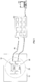
- FIG. 1 shows an exemplary system for monitoring a gaseous fire suppression blend.
- Multiple sensors 20 are located in a protected space 10. Only one sensor 20 is shown in FIG. 1 for simplicity.
- Each sensor includes subunits 30, each having a wavelength source and detector.
- Each sensor subunit is connected to a central control unit 50 by fiber optic cables 40. While FIG. 1 shows each sensor subunit individually connected, it is also contemplated that the subunits from a single sensor may be connected to the central control unit through a shared connection.
- the central control unit may be optionally connected to a data collection and storage device 60.
- FIG. 2 shoes an exemplary system for monitoring a gaseous fire suppression blend.
- Multiple sensors 20 are located in a protected space 10. One sensor is shown for simplicity.
- the sensor 20 includes at least one tube 70 that can withdraw the sample from the protected space using a vacuum (vacuum source not shown). While FIG. 2 shows sensor 20 employing two tubes 70 it is contemplated that a single tube could suffice because the measurement method is non-destructive.
- the tubes 70 deliver the samples to the central analyzer 80. When there is a single tube connecting the sensor and the central analyzer the central analyzer will analyze for the components of the blend as desired. There is also the possibility of two central analyzers.
- the central analyzer may be optionally connected to a data collection and storage device 60.
Landscapes
- Chemical & Material Sciences (AREA)
- Physics & Mathematics (AREA)
- Health & Medical Sciences (AREA)
- Engineering & Computer Science (AREA)
- Spectroscopy & Molecular Physics (AREA)
- General Health & Medical Sciences (AREA)
- Immunology (AREA)
- Life Sciences & Earth Sciences (AREA)
- Analytical Chemistry (AREA)
- Biochemistry (AREA)
- Pathology (AREA)
- General Physics & Mathematics (AREA)
- Combustion & Propulsion (AREA)
- Emergency Management (AREA)
- Business, Economics & Management (AREA)
- Public Health (AREA)
- Dispersion Chemistry (AREA)
- Mechanical Engineering (AREA)
- General Engineering & Computer Science (AREA)
- Investigating Or Analysing Materials By Optical Means (AREA)
Abstract
Description
- Exemplary embodiments pertain to the art of measuring the levels or concentration of a fire suppression agent in a protected space.
- In general, existing fire suppression systems include a fire suppression agent distribution system that distributes the fire suppression agent to the aircraft engine bays and selected cargo compartments. These areas form a protected space or spaces. In a typical application, in order to effectively extinguish a fire, concentrations of a fire suppression agent must be in excess of a specified minimum concentration for a specified period of time. Lower concentrations or shorter time periods reduce effectiveness, and conversely, higher concentrations and/or longer time periods waste suppression agent. Additionally, oversizing the system can result in concentrations that have an undesired effect.
- It would be desirable to have a system for monitoring the concentration of a fire suppression agent, particularly for monitoring a gaseous fire suppression blend.
- Disclosed is a system for monitoring a gaseous fire suppression blend including a sensor array having a plurality of sensors disposed in a protected space, wherein the sensor array can detect and quantify more than one component of the gaseous fire suppression blend.
- In addition to one or more of the features described above, or as an alternative to any of the foregoing embodiments, each of the plurality of sensors include one or more optical sensors that can emit and detect multiple wavelengths. In some embodiments each sensor includes a single source which can emit multiple wavelengths and the sensor includes multiple detectors that detect a single wavelength. In some embodiments each sensor includes multiple sources that emit single wavelengths and multiple detectors that detect a single wavelength. In some embodiments each sensor includes more than one source wherein each of the more than one source emits a different range of wavelengths and more than one detector which can detect a single wavelength or a range of wavelengths.
- In addition to one or more of the features described above, or as an alternative to any of the foregoing embodiments, each of the plurality of optical sensors has a lower detection limit less than half of the desired minimum concentration of the gaseous fire suppression blend components.
- In addition to one or more of the features described above, or as an alternative to any of the foregoing embodiments, each of the plurality of optical sensors has a lower detection limit an order of magnitude below the desired minimum concentration of the gaseous fire suppression blend components.
- In addition to one or more of the features described above, or as an alternative to any of the foregoing embodiments, each of the plurality of optical sensors has an upper detection limit two times greater than a maximum allowed concentration of the gaseous fire suppression blend components.
- In addition to one or more of the features described above, or as an alternative to any of the foregoing embodiments, signals from the plurality of optical sensors are processed by a central control unit.
- In addition to one or more of the features described above, or as an alternative to any of the foregoing embodiments, the plurality of optical sensors are connected to the central control unit by fiber optic cable.
- In addition to one or more of the features described above, or as an alternative to any of the foregoing embodiments, the plurality of sensors comprises sets of optical sensors for detecting different components of the gaseous fire suppression blend.
- In addition to one or more of the features described above, or as an alternative to any of the foregoing embodiments, the plurality of sensors are disposed at different locations in the protected space.
- In addition to one or more of the features described above, or as an alternative to any of the foregoing embodiments, the plurality of sensors comprise sensor tubes and a vacuum source.
- In addition to one or more of the features described above, or as an alternative to any of the foregoing embodiments, the sensor tubes are in operable communication with a central analyzer.
- In addition to one or more of the features described above, or as an alternative to any of the foregoing embodiments, the central analyzer can emit and detect multiple wavelengths.
- Also disclosed is a method of monitoring a gaseous fire suppression blend in a protected space including measuring concentrations of more than one component of the gaseous fire suppression blend in the protected space.
- In addition to one or more of the features described above, or as an alternative to any of the foregoing embodiments, the concentrations are measured over time using multiple samples.
- In addition to one or more of the features described above, or as an alternative to any of the foregoing embodiments, the concentration is measured continuously over time.
- In addition to one or more of the features described above, or as an alternative to any of the foregoing embodiments, each component of the gaseous fire suppression blend absorbs light at a characteristic wavelength.
- In addition to one or more of the features described above, or as an alternative to any of the foregoing embodiments, light absorption of the sample at the characteristic wavelengths is compared to calibration curves to determine concentration.
- In addition to one or more of the features described above, or as an alternative to any of the foregoing embodiments, measuring the concentrations employs sensors located at the different locations in the protected space.
- In addition to one or more of the features described above, or as an alternative to any of the foregoing embodiments, measuring the concentrations employs a central analyzer using samples collected by sensors located at different locations in the protected space
- The following descriptions should not be considered limiting in any way. With reference to the accompanying drawings, like elements are numbered alike:
FIG. 1 and2 show exemplary systems for monitoring a gaseous fire suppression blend. - A detailed description of one or more embodiments of the disclosed apparatus and method are presented herein by way of exemplification and not limitation with reference to the Figures.
- Due to concerns about ozone depletion associated with HALON 1301 there is great interest in developing the use of gaseous fire suppression blends that pose less of an ozone depletion risk. Suggested replacements for HALON 1301 include CF3I and blends including CF3I such as CF3I/HFC-125, CF3I/HCFO-1233zd(E), CF3I/Novec 1230 and CF3I/CO2. Currently there is no system or method for detecting the different components of these blends simultaneously or their distribution in a protected space. Each component of the gaseous fire suppression blend may have different distribution rate in the protected space due to differences in molecular weight and other physical characteristics. Accordingly, there is currently no way to assure that the desired blend proportions are distributed throughout the volume (space) to be protected.
- This need can be addressed by a system and method for monitoring the concentration of gaseous fire suppression blend components. The system and method take advantage of the fact that each component of the gaseous fire suppression blend has at least one characteristic wavelength. A characteristic wavelength is defined herein as a wavelength at which only one component of the gaseous fire suppression blend absorbs. This allows the system and method disclosed herein to use the characteristic wavelength for each component to determine the concentration of that component in the sample taken from that location at that point in time. Because the method of measurement is non-destructive the same sample can be used to determine the concentration of each component of the gaseous fire suppression blend. It is contemplated that useful wavelengths include wavelengths in the infrared, visible and ultraviolet spectrums. Exemplary components and wavelengths are shown in the table below.
Suppression Agent Spectral Region Characteristic Frequency Reason CF3I UV 268 nm C-I electronic Transition Novec 1230 UV 307 nm C=O electronic transition HFC-125 IR 3000 cm-1 C-H stretch CO2 IR 2360 cm-1 C=O Stretch HCFO-1233zd(E) IR 1680-1640 cm-1 C=C stretch - The amount of absorption can be correlated to the corresponding concentration of the component using a calibration curve established using known concentrations the component to generate the curve.
- Exemplary blends and the associated wavelength combinations are shown in the following table.
Blend No. Component 1Component 2Frequencies 1 CF3I HFC-125 268 nm / 3000 cm -12 CF3I Novec 1230 268 nm / 307 nm 3 CF3I CO2 268 nm / 2360 cm-1 4 CF3I HCFO-1233zd(E) 268 nm / 1680 cm-1 5 Novec 1230 CO2 307 nm / 2360 cm-1 - The system includes a sensor array. The sensor array includes a plurality of sensors disposed in the protected space. The sensor array may include greater than or equal to 10 sensors, or, greater than or equal to 15 sensors, or, greater than or equal to 20 sensors. The sensors may distributed throughout the protected space at regular intervals or a specified locations.
- The sensor may be an optical sensor which can emit and detect the desired wavelengths. The sensor may include several subunits each of which can emit and detect a single wavelength or a range of wavelengths. Alternatively, the sensor may include a multiwavelength source and a multiwavelength detector. In yet another option, the sensor may include a multiwavelength source and multiple detectors. The sensor may transmit the data to a central control unit to be compared to an appropriate calibration curve. Alternatively, the data can be compared to an appropriate calibration curve within the sensor and the results transmitted to a central unit.
- The optical sensors may be connected to the central control unit using fiber optic cable. When connected by fiber optic cable the central control unit may function as the light source with the detector(s) located within the sensor. The sensor can include a single detector for multiple wavelengths, multiple detectors for single wavelengths or multiple detectors which can detect a range of wavelengths.
- The optical sensor has a lower detection limit less half than the desired minimum concentration of the gaseous fire suppression blend component that it is measuring. The lower detection limit of the optical sensor may be an order of magnitude less than the desired minimum concentration of the gaseous fire suppression blend component. The optical sensor has an upper detection limit two times greater than a maximum allowed concentration of the gaseous fire suppression blend component it is measuring.
- Alternatively the sensor may include a vacuum pump and sensor tubes which obtain samples and communicate the samples to a central analyzer for analysis. The central analyzer may be a spectrophotometer that employs the desired wavelengths and correlates the absorption to concentration using a calibration curve. The central analyzer has a lower detection limit less than half the desired minimum concentration of the gaseous fire suppression blend components and an upper detection limit two times greater than the maximum allowed concentration of the gaseous fire suppression blend components.
- The protected space may be sampled at a single point in time, at several points in time, or over a period time. When sampled over a period of time multiple samples/data points may be obtained or the protected space may be sampled continuously.
- Turning now to the Figures,
FIG. 1 shows an exemplary system for monitoring a gaseous fire suppression blend.Multiple sensors 20 are located in a protectedspace 10. Only onesensor 20 is shown inFIG. 1 for simplicity. Each sensor includessubunits 30, each having a wavelength source and detector. Each sensor subunit is connected to acentral control unit 50 byfiber optic cables 40. WhileFIG. 1 shows each sensor subunit individually connected, it is also contemplated that the subunits from a single sensor may be connected to the central control unit through a shared connection. The central control unit may be optionally connected to a data collection andstorage device 60. -
FIG. 2 shoes an exemplary system for monitoring a gaseous fire suppression blend.Multiple sensors 20 are located in a protectedspace 10. One sensor is shown for simplicity. Thesensor 20 includes at least onetube 70 that can withdraw the sample from the protected space using a vacuum (vacuum source not shown). WhileFIG. 2 showssensor 20 employing twotubes 70 it is contemplated that a single tube could suffice because the measurement method is non-destructive. Thetubes 70 deliver the samples to thecentral analyzer 80. When there is a single tube connecting the sensor and the central analyzer the central analyzer will analyze for the components of the blend as desired. There is also the possibility of two central analyzers. The central analyzer may be optionally connected to a data collection andstorage device 60. - The terminology used herein is for the purpose of describing particular embodiments only and is not intended to be limiting of the present disclosure. As used herein, the singular forms "a", "an" and "the" are intended to include the plural forms as well, unless the context clearly indicates otherwise. It will be further understood that the terms "comprises" and/or "comprising," when used in this specification, specify the presence of stated features, integers, steps, operations, elements, and/or components, but do not preclude the presence or addition of one or more other features, integers, steps, operations, element components, and/or groups thereof.
- While the disclosure has been described with reference to an exemplary embodiment or embodiments, it will be understood by those skilled in the art that various changes may be made and equivalents may be substituted for elements thereof without departing from the scope of the present disclosure. In addition, many modifications may be made to adapt a particular situation or material to the teachings of the present disclosure without departing from the essential scope thereof. Therefore, it is intended that the disclosure not be limited to the particular embodiment disclosed as the best mode contemplated for carrying out this disclosure, but that the disclosure will include all embodiments falling within the scope of the claims.
Claims (15)
- A system for monitoring a gaseous fire suppression blend comprising:
a sensor array having a plurality of sensors (20) disposed in a protected space (10), wherein the sensor array can detect and quantify more than one component of the gaseous fire suppression blend. - The system of claim 1, wherein each of the plurality of sensors are optical sensors that can emit and detect multiple wavelengths.
- The system of claim 2, wherein each of the plurality of optical sensors has a lower detection limit less than a desired minimum concentration of the gaseous fire suppression blend components; and/or wherein each of the plurality of optical sensors has an upper detection limit greater than a maximum allowed concentration of the gaseous fire suppression blend components.
- The system of claim 2 or 3, wherein signals from the plurality of optical sensors are processed by a central control unit (50); optionally wherein the plurality of optical sensors are connected to the central control unit by fiber optic cable (40).
- The system of any preceding claim, wherein each of the plurality of sensors comprise a single source which can emit multiple wavelengths and a single detector which can detect multiple wavelengths.
- The system of any of claims 1 to 4, wherein each of the plurality of sensors comprise a single source which can emit multiple wavelengths and multiple detectors which can detect single wavelengths.
- The system of any of claims 1 to 4, wherein each of the plurality of sensors comprise a multiple sources which can emit single wavelengths and multiple detectors which can detect single wavelengths.
- The system of any preceding claim, wherein the plurality of sensors are disposed at different locations in the protected space.
- The system of any preceding claim, wherein the plurality of sensors comprise sensor tubes (70) and a vacuum source; optionally wherein the sensor tubes are in operable communication with a central analyzer (80); further optionally wherein the central analyzer is a central spectrophotometer that can emit and detect multiple wavelengths.
- A method of monitoring a gaseous fire suppression blend in a protected space (10) comprising:
measuring concentrations of more than one component of the gaseous fire suppression blend in a sample in the protected space. - The method of claim 10, wherein the concentrations of components of the gaseous fire suppression blend is measured over time using multiple samples.
- The method of claim 10 or 11, wherein the concentrations of components of the gaseous fire suppression blend is measured continuously.
- The method of claim 10, 11 or 12, wherein each component of the gaseous fire suppression blend absorbs light at a characteristic wavelength; optionally wherein light absorption of the sample at the characteristic wavelengths is compared to a calibration curve to determine concentration.
- The method of any of claims 10 to 13, wherein measuring the concentration employs sensors (20) located at the different locations in the protected space (10).
- The method of any of claims 10 to 14, wherein measuring the concentration employs a central analyzer using samples collected by sensors located at different locations in the protected space.
Applications Claiming Priority (1)
| Application Number | Priority Date | Filing Date | Title |
|---|---|---|---|
| US16/388,959 US11326998B2 (en) | 2019-04-19 | 2019-04-19 | System and method for monitoring a fire suppression blend |
Publications (1)
| Publication Number | Publication Date |
|---|---|
| EP3726198A1 true EP3726198A1 (en) | 2020-10-21 |
Family
ID=68762580
Family Applications (1)
| Application Number | Title | Priority Date | Filing Date |
|---|---|---|---|
| EP19212840.3A Pending EP3726198A1 (en) | 2019-04-19 | 2019-12-02 | System and method for monitoring a fire suppression blend |
Country Status (2)
| Country | Link |
|---|---|
| US (1) | US11326998B2 (en) |
| EP (1) | EP3726198A1 (en) |
Families Citing this family (3)
| Publication number | Priority date | Publication date | Assignee | Title |
|---|---|---|---|---|
| US10953257B2 (en) | 2019-04-19 | 2021-03-23 | Kidde Technologies, Inc. | Fire suppression composition |
| US11291876B2 (en) | 2019-04-19 | 2022-04-05 | Kidde Technologies, Inc. | Fire suppression agent composition |
| US11324982B1 (en) * | 2020-10-19 | 2022-05-10 | Kidde Technologies, Inc. | Fire suppression compositions |
Citations (5)
| Publication number | Priority date | Publication date | Assignee | Title |
|---|---|---|---|---|
| US5281816A (en) * | 1991-07-04 | 1994-01-25 | Spectronix Ltd. | Method and apparatus for detecting hydrocarbon vapors in a monitored area |
| US6181426B1 (en) * | 1998-04-03 | 2001-01-30 | Mcdonnell Douglas Corporation | Gas concentration monitoring system |
| US20140231660A1 (en) * | 2013-01-24 | 2014-08-21 | Airbus Operations (Sas) | Method and device for measuring the concentration of extinguishing agent in a fire zone |
| CN108195796A (en) * | 2017-12-28 | 2018-06-22 | 中国科学技术大学 | Aircraft gas extinguishing agent concentration measurement system and method based on TDLAS |
| US20180217054A1 (en) * | 2015-08-18 | 2018-08-02 | Tokushima University | Concentration measurement device |
Family Cites Families (82)
| Publication number | Priority date | Publication date | Assignee | Title |
|---|---|---|---|---|
| US2692649A (en) | 1951-03-03 | 1954-10-26 | Union Oil Co | Apparatus for extinguishing fires |
| US4179218A (en) * | 1978-05-15 | 1979-12-18 | The Boeing Company | Particle size analyzer |
| JPS60139262A (en) | 1983-12-27 | 1985-07-24 | ホーチキ株式会社 | Fire extinguishing agent for use with washing |
| JPH0689690B2 (en) * | 1987-03-18 | 1994-11-09 | 株式会社ユニシアジェックス | Air-fuel ratio learning controller for internal combustion engine |
| US5126570A (en) * | 1988-09-27 | 1992-06-30 | The Standard Oil Company | Sensor and method for measuring alcohol concentration in an alcohol-gasoline mixture |
| US5155357A (en) * | 1990-07-23 | 1992-10-13 | Massachusetts Institute Of Technology | Portable mass spectrometer |
| US5409666A (en) * | 1991-08-08 | 1995-04-25 | Minnesota Mining And Manufacturing Company | Sensors and methods for sensing |
| US5611210A (en) | 1993-03-05 | 1997-03-18 | Ikon Corporation | Fluoroiodocarbon blends as CFC and halon replacements |
| US5502222A (en) | 1994-06-01 | 1996-03-26 | Schering Corporation | Process for preparing delta 9,11 and 21-chloro corticosteroids |
| JPH08277389A (en) | 1995-04-06 | 1996-10-22 | Matsushita Electric Ind Co Ltd | Mixed working fluid and heat pump device using the same |
| US6064064A (en) * | 1996-03-01 | 2000-05-16 | Fire Sentry Corporation | Fire detector |
| US6518574B1 (en) * | 1996-03-01 | 2003-02-11 | Fire Sentry Corporation | Fire detector with multiple sensors |
| CA2176515C (en) | 1996-05-14 | 1996-10-22 | Eckhard H. Biller | Fire suppressant foam, dispersant and detergent eckhard iii - formula |
| JP3663891B2 (en) * | 1998-02-20 | 2005-06-22 | 株式会社島津製作所 | Gas chromatograph |
| US6116348A (en) | 1998-07-17 | 2000-09-12 | R-Amtech International, Inc. | Method and apparatus for fire extinguishing |
| AU3233400A (en) * | 1999-02-19 | 2000-09-04 | Primex Aerospace Company | Fire suppression composition and device |
| US6284196B1 (en) * | 1999-04-01 | 2001-09-04 | Bp Corporation North America Inc. | Apparatus for monitor and control of an ammoxidation reactor with a fourier transform infrared spectrometer |
| US6902009B1 (en) | 2000-08-21 | 2005-06-07 | Pacific Scientific | Fire extinguisher with means for preventing freezing at outlet |
| US6526764B1 (en) | 2000-09-27 | 2003-03-04 | Honeywell International Inc. | Hydrofluorocarbon refrigerant compositions soluble in lubricating oil |
| DE50210665D1 (en) * | 2002-02-13 | 2007-09-20 | Fraunhofer Ges Forschung | QUASI-STATIC DEFLECTION DEVICE FOR SPECTROMETERS |
| US6844554B2 (en) * | 2002-06-28 | 2005-01-18 | Instrumentarium Corp. | Method and arrangement for determining the concentration of a gas component in a gas mixture |
| US7048068B2 (en) * | 2003-07-23 | 2006-05-23 | Paulkovich Michael B | Fire extinguishing system for large structures |
| US9592412B2 (en) | 2003-11-04 | 2017-03-14 | Honeywell International Inc. | Aerosol compositions containing fluorine substituted olefins and methods and systems using same |
| US20050115721A1 (en) * | 2003-12-02 | 2005-06-02 | Blau Reed J. | Man-rated fire suppression system |
| US8039642B2 (en) * | 2003-12-09 | 2011-10-18 | Life Technologies Corporation | Pyrenyloxysulfonic acid fluorescent agents |
| US7384519B2 (en) | 2003-12-23 | 2008-06-10 | Honeywell International Inc. | Process for the purification of pharmaceutical grade HFC-134a and polymer grade HCFC-22 |
| US20050145820A1 (en) | 2004-01-06 | 2005-07-07 | Waldrop Stephanie D. | Compositions and methods useful for synergistic combustion suppression |
| US7142105B2 (en) * | 2004-02-11 | 2006-11-28 | Southwest Sciences Incorporated | Fire alarm algorithm using smoke and gas sensors |
| US7321425B2 (en) * | 2004-12-20 | 2008-01-22 | Honeywell International Inc. | Sensor and methods for measuring select components in sheetmaking systems |
| KR20070090939A (en) | 2004-12-21 | 2007-09-06 | 허니웰 인터내셔널 인코포레이티드 | Stabilized Iodine Carbon Composition |
| WO2006076649A2 (en) * | 2005-01-12 | 2006-07-20 | Eclipse Aviation Corporation | Fire suppression systems |
| DE102005002106B3 (en) * | 2005-01-14 | 2006-04-13 | Drägerwerk AG | Spectroscopic device for qualitative and quantitative analysis of gas mixtures, useful in medical and safety applications, comprising refractive-diffractive elements for wavelength-dependent imaging |
| US20060243944A1 (en) | 2005-03-04 | 2006-11-02 | Minor Barbara H | Compositions comprising a fluoroolefin |
| US7456961B2 (en) * | 2005-04-14 | 2008-11-25 | The Boeing Company | Apparatus and method for detecting aerosol |
| GB0611742D0 (en) | 2006-06-14 | 2006-07-26 | Ineos Fluor Holdings Ltd | Desiccants for fluids |
| US7597744B2 (en) | 2006-07-12 | 2009-10-06 | Honeywell International Inc. | Use of molecular sieves for the removal of HFC-23 from fluorocarbon products |
| JP2008146741A (en) * | 2006-12-08 | 2008-06-26 | Matsushita Electric Ind Co Ltd | Optical pickup device |
| KR100888954B1 (en) * | 2007-02-02 | 2009-03-17 | 안강호 | Condensation particle counter |
| KR20090034081A (en) | 2007-10-02 | 2009-04-07 | 삼성전자주식회사 | Multilayer semiconductor package device and manufacturing method thereof |
| TW200930801A (en) | 2007-10-31 | 2009-07-16 | Du Pont | Compositions comprising iodotrifluoromethane and uses thereof |
| ITRM20080357A1 (en) | 2008-07-01 | 2010-01-02 | Explosafe Internat B V | EXTINGUISHING AGENTS BASED ON FLUOROIODO-CARBIDE AND HYDROFLUOROCARBONS MIXTURES. |
| US8598107B2 (en) | 2009-01-13 | 2013-12-03 | Honeywell International Inc. | Azeotrope-like compositions of pentafluoroethane and trifluoroiodomethane |
| US8004684B2 (en) | 2009-04-09 | 2011-08-23 | Kidde Technologies, Inc. | Sensor head for a dry powder agent |
| US8192653B2 (en) * | 2009-09-30 | 2012-06-05 | EarthCleanCorporation | Fire suppression biodegradable suspension forming compositions |
| BR112013009852A2 (en) * | 2010-10-22 | 2016-11-22 | Kenneth Susko | optical probe containing oxygen, temperature, and pressure sensors and monitoring and control systems containing them |
| US9298193B2 (en) * | 2010-10-22 | 2016-03-29 | Kenneth Susko | Optical probe containing oxygen, temperature, and pressure sensors and monitoring and control systems containing the same |
| US8096366B2 (en) | 2010-12-10 | 2012-01-17 | American Pacific Corporation | Environmentally beneficial and effective hydrochlorofluorocarbon compositions for fire extinguishing applications |
| US8733463B2 (en) * | 2011-01-23 | 2014-05-27 | The Boeing Company | Hybrid cargo fire-suppression agent distribution system |
| US9207172B2 (en) | 2011-05-26 | 2015-12-08 | Kidde Technologies, Inc. | Velocity survey with powderizer and agent flow indicator |
| US9796480B2 (en) * | 2011-11-15 | 2017-10-24 | United Parcel Service Of America, Inc. | System and method of notification of an aircraft cargo fire within a container |
| WO2013118666A1 (en) * | 2012-02-06 | 2013-08-15 | 株式会社ニコン | Spectroscope and microspectroscopic system |
| US9713732B2 (en) | 2012-03-16 | 2017-07-25 | Meggitt Safety Systems, Inc. | Fire suppressing materials and systems and methods of use |
| US9034202B2 (en) * | 2012-03-16 | 2015-05-19 | Meggitt Safety Systems Inc. | Fire suppressing materials and systems and methods of use |
| US10561353B2 (en) * | 2016-06-01 | 2020-02-18 | Glysens Incorporated | Biocompatible implantable sensor apparatus and methods |
| US9182331B2 (en) * | 2012-08-31 | 2015-11-10 | The Boeing Company | Measurement of solid, aerosol, vapor, liquid and gaseous concentration and particle size |
| US9526931B2 (en) * | 2012-12-07 | 2016-12-27 | The Boeing Company | Cargo fire-suppression agent distribution system |
| ITTO20121099A1 (en) | 2012-12-18 | 2014-06-19 | Tazzetti S P A | NEW ENVIRONMENTAL REFRIGERATING MIXTURES |
| CN104870977B (en) * | 2012-12-20 | 2018-03-27 | 雷迪奥米特医学公司 | Device for detecting components in a sample |
| US9372177B2 (en) * | 2013-03-15 | 2016-06-21 | The Boeing Company | Method and system for detecting exposure of composites to high-temperature |
| US9233264B2 (en) * | 2013-08-23 | 2016-01-12 | Fire Flighters Llc | Fire suppression system for aircraft storage containers |
| EP2960235B1 (en) | 2014-06-25 | 2018-09-26 | Symrise AG | Tetrahydrofuran derivatives as fragrances |
| US10343003B2 (en) * | 2014-10-02 | 2019-07-09 | The Boeing Company | Aircraft fire suppression system and method |
| CN104483288B (en) * | 2014-12-23 | 2017-09-15 | 深圳因特安全技术有限公司 | Perfluoroisopropyl hexanone extinguishing chemical recognition detection method |
| GB201501598D0 (en) | 2015-01-30 | 2015-03-18 | Mexichem Fluor Sa De Cv | Compositions |
| JP6690092B2 (en) * | 2016-07-27 | 2020-04-28 | 富士通株式会社 | Heat source detection device, heat source detection method, and heat source detection program |
| US10815409B2 (en) | 2017-10-06 | 2020-10-27 | Honeywell International Inc. | Heat transfer compositions, methods and systems |
| US10655040B2 (en) | 2017-01-13 | 2020-05-19 | Honeywell International Inc. | Refrigerant, heat transfer compositions, methods, and systems |
| JP2018153463A (en) | 2017-03-17 | 2018-10-04 | Agc株式会社 | Fire-extinguishing agent composition and fire-extinguishing system |
| JP6870423B2 (en) * | 2017-03-29 | 2021-05-12 | 富士通株式会社 | Signal quality measuring device and signal quality measuring method |
| KR20190140040A (en) | 2017-05-08 | 2019-12-18 | 허니웰 인터내셔날 인코포레이티드 | HFO-1224YD Digestive Compositions, Systems and Methods |
| US11021721B2 (en) * | 2017-07-20 | 2021-06-01 | Alliance For Sustainable Energy, Llc | Genetically engineered Pseudomonas strains capable of metabolizing ethylene glycol and its metabolic intermediates |
| TWI843706B (en) | 2017-09-19 | 2024-06-01 | 美商哈尼威爾國際公司 | Heat transfer methods, systems and compositions |
| EP3710550A4 (en) | 2017-11-17 | 2021-09-29 | Honeywell International Inc. | HEAT TRANSFER COMPOSITIONS, PROCEDURES AND SYSTEMS |
| JP7284754B2 (en) | 2017-11-30 | 2023-05-31 | ハネウェル・インターナショナル・インコーポレーテッド | Heat transfer composition, method and system |
| PL3717589T3 (en) | 2017-11-30 | 2026-05-11 | Honeywell International Inc. | Heat transfer compositions, methods, and systems |
| US10814150B2 (en) * | 2017-12-02 | 2020-10-27 | M-Fire Holdings Llc | Methods of and system networks for wireless management of GPS-tracked spraying systems deployed to spray property and ground surfaces with environmentally-clean wildfire inhibitor to protect and defend against wildfires |
| JP6545338B1 (en) * | 2018-08-31 | 2019-07-17 | 日立ジョンソンコントロールズ空調株式会社 | Refrigeration cycle device |
| US10973579B2 (en) * | 2018-12-28 | 2021-04-13 | Industrial Technology Research Institute | Optical system |
| US11291876B2 (en) | 2019-04-19 | 2022-04-05 | Kidde Technologies, Inc. | Fire suppression agent composition |
| US20200332192A1 (en) | 2019-04-19 | 2020-10-22 | Kidde Technologies, Inc. | Method and apparatus for inhibiting corrosion from fire suppression agents in situ |
| US10953257B2 (en) | 2019-04-19 | 2021-03-23 | Kidde Technologies, Inc. | Fire suppression composition |
| US20200330808A1 (en) | 2019-04-19 | 2020-10-22 | Kidde Technologies, Inc. | Method and apparatus for stabilizing fire suppression agents in situ |
-
2019
- 2019-04-19 US US16/388,959 patent/US11326998B2/en active Active
- 2019-12-02 EP EP19212840.3A patent/EP3726198A1/en active Pending
Patent Citations (5)
| Publication number | Priority date | Publication date | Assignee | Title |
|---|---|---|---|---|
| US5281816A (en) * | 1991-07-04 | 1994-01-25 | Spectronix Ltd. | Method and apparatus for detecting hydrocarbon vapors in a monitored area |
| US6181426B1 (en) * | 1998-04-03 | 2001-01-30 | Mcdonnell Douglas Corporation | Gas concentration monitoring system |
| US20140231660A1 (en) * | 2013-01-24 | 2014-08-21 | Airbus Operations (Sas) | Method and device for measuring the concentration of extinguishing agent in a fire zone |
| US20180217054A1 (en) * | 2015-08-18 | 2018-08-02 | Tokushima University | Concentration measurement device |
| CN108195796A (en) * | 2017-12-28 | 2018-06-22 | 中国科学技术大学 | Aircraft gas extinguishing agent concentration measurement system and method based on TDLAS |
Also Published As
| Publication number | Publication date |
|---|---|
| US20200333233A1 (en) | 2020-10-22 |
| US11326998B2 (en) | 2022-05-10 |
Similar Documents
| Publication | Publication Date | Title |
|---|---|---|
| US11326998B2 (en) | System and method for monitoring a fire suppression blend | |
| Washenfelder et al. | Measurement of glyoxal using an incoherent broadband cavity enhanced absorption spectrometer | |
| EP0380580B1 (en) | Multi-channel molecular gas analysis by laser-activated raman light scattering | |
| KR101098124B1 (en) | Multigas Monitoring And Detection System | |
| JP2788036B2 (en) | Optical gas analyzer | |
| EP1693665B1 (en) | Method and apparatus for trace gas detection | |
| RU2002106861A (en) | METHOD FOR DETERMINING THE STATE OF BIOLOGICAL TISSUE (options) AND DIAGNOSTIC SYSTEM FOR ITS IMPLEMENTATION | |
| DE19925196A1 (en) | Gas sensor arrangement | |
| ES2146232T3 (en) | NON-INVASIVE TEST. | |
| JP2005513491A (en) | Method and apparatus for the determination of light transport parameters and analytes in biological matrices | |
| DE2442589A1 (en) | GAS MEASURING DEVICE AND METHOD FOR CONTINUOUS MEASUREMENT OF THE CO LOW 2 CONTENT IN BREATHING GASES | |
| CN101606052A (en) | Apparatus and method for acquiring image data from turbid media | |
| WO2006035012A1 (en) | Spectrometric measuring head for harvesting machines and other agricultural application machines | |
| US20200096439A1 (en) | Method, Apparatus and System for Examination of a Free-Flowing Sample | |
| US20040090628A1 (en) | Mappable atmospheric pollutant detection system | |
| DE102006018862A1 (en) | Device for the spectroscopic analysis of a gas | |
| US20040135088A1 (en) | Mid infra red analysis | |
| Farhani et al. | Optimal estimation method retrievals of stratospheric ozone profiles from a DIAL | |
| EP4284232B1 (en) | A method and device for offset compensation | |
| KR20090109027A (en) | Method and device for measuring internal quality of multichannel fruits | |
| Mijić et al. | Data quality assurance for atmospheric probing and modeling: characterization of Belgrade Raman lidar station | |
| Greensill et al. | An investigation into the determination of the maturity of pawpaws (Carica papaya) from NIR transmission spectra | |
| Cuomo et al. | Lidar measurements of atmospheric transmissivity | |
| WO2016055527A2 (en) | Optical detector module, measurement system and method of detecting presence of a substance in a test material | |
| WO2008029335A3 (en) | Displacement detection in optical tomography systems |
Legal Events
| Date | Code | Title | Description |
|---|---|---|---|
| PUAI | Public reference made under article 153(3) epc to a published international application that has entered the european phase |
Free format text: ORIGINAL CODE: 0009012 |
|
| STAA | Information on the status of an ep patent application or granted ep patent |
Free format text: STATUS: THE APPLICATION HAS BEEN PUBLISHED |
|
| AK | Designated contracting states |
Kind code of ref document: A1 Designated state(s): AL AT BE BG CH CY CZ DE DK EE ES FI FR GB GR HR HU IE IS IT LI LT LU LV MC MK MT NL NO PL PT RO RS SE SI SK SM TR |
|
| AX | Request for extension of the european patent |
Extension state: BA ME |
|
| STAA | Information on the status of an ep patent application or granted ep patent |
Free format text: STATUS: REQUEST FOR EXAMINATION WAS MADE |
|
| 17P | Request for examination filed |
Effective date: 20210419 |
|
| RBV | Designated contracting states (corrected) |
Designated state(s): AL AT BE BG CH CY CZ DE DK EE ES FI FR GB GR HR HU IE IS IT LI LT LU LV MC MK MT NL NO PL PT RO RS SE SI SK SM TR |
|
| STAA | Information on the status of an ep patent application or granted ep patent |
Free format text: STATUS: EXAMINATION IS IN PROGRESS |
|
| 17Q | First examination report despatched |
Effective date: 20221111 |