EP3726168B1 - Cavity muffler and refrigerator - Google Patents
Cavity muffler and refrigerator Download PDFInfo
- Publication number
- EP3726168B1 EP3726168B1 EP18888045.4A EP18888045A EP3726168B1 EP 3726168 B1 EP3726168 B1 EP 3726168B1 EP 18888045 A EP18888045 A EP 18888045A EP 3726168 B1 EP3726168 B1 EP 3726168B1
- Authority
- EP
- European Patent Office
- Prior art keywords
- muffler
- sealing body
- air outlet
- vacuum pump
- chamber
- Prior art date
- Legal status (The legal status is an assumption and is not a legal conclusion. Google has not performed a legal analysis and makes no representation as to the accuracy of the status listed.)
- Active
Links
Images




Classifications
-
- F—MECHANICAL ENGINEERING; LIGHTING; HEATING; WEAPONS; BLASTING
- F04—POSITIVE - DISPLACEMENT MACHINES FOR LIQUIDS; PUMPS FOR LIQUIDS OR ELASTIC FLUIDS
- F04B—POSITIVE-DISPLACEMENT MACHINES FOR LIQUIDS; PUMPS
- F04B39/00—Component parts, details, or accessories, of pumps or pumping systems specially adapted for elastic fluids, not otherwise provided for in, or of interest apart from, groups F04B25/00 - F04B37/00
- F04B39/0027—Pulsation and noise damping means
- F04B39/0083—Pulsation and noise damping means using blow off silencers
-
- F—MECHANICAL ENGINEERING; LIGHTING; HEATING; WEAPONS; BLASTING
- F04—POSITIVE - DISPLACEMENT MACHINES FOR LIQUIDS; PUMPS FOR LIQUIDS OR ELASTIC FLUIDS
- F04B—POSITIVE-DISPLACEMENT MACHINES FOR LIQUIDS; PUMPS
- F04B39/00—Component parts, details, or accessories, of pumps or pumping systems specially adapted for elastic fluids, not otherwise provided for in, or of interest apart from, groups F04B25/00 - F04B37/00
- F04B39/0027—Pulsation and noise damping means
- F04B39/0033—Pulsation and noise damping means with encapsulations
-
- F—MECHANICAL ENGINEERING; LIGHTING; HEATING; WEAPONS; BLASTING
- F04—POSITIVE - DISPLACEMENT MACHINES FOR LIQUIDS; PUMPS FOR LIQUIDS OR ELASTIC FLUIDS
- F04B—POSITIVE-DISPLACEMENT MACHINES FOR LIQUIDS; PUMPS
- F04B39/00—Component parts, details, or accessories, of pumps or pumping systems specially adapted for elastic fluids, not otherwise provided for in, or of interest apart from, groups F04B25/00 - F04B37/00
- F04B39/0027—Pulsation and noise damping means
- F04B39/0055—Pulsation and noise damping means with a special shape of fluid passage, e.g. bends, throttles, diameter changes, pipes
- F04B39/0061—Pulsation and noise damping means with a special shape of fluid passage, e.g. bends, throttles, diameter changes, pipes using muffler volumes
-
- F—MECHANICAL ENGINEERING; LIGHTING; HEATING; WEAPONS; BLASTING
- F25—REFRIGERATION OR COOLING; COMBINED HEATING AND REFRIGERATION SYSTEMS; HEAT PUMP SYSTEMS; MANUFACTURE OR STORAGE OF ICE; LIQUEFACTION SOLIDIFICATION OF GASES
- F25D—REFRIGERATORS; COLD ROOMS; ICE-BOXES; COOLING OR FREEZING APPARATUS NOT OTHERWISE PROVIDED FOR
- F25D17/00—Arrangements for circulating cooling fluids; Arrangements for circulating gas, e.g. air, within refrigerated spaces
- F25D17/04—Arrangements for circulating cooling fluids; Arrangements for circulating gas, e.g. air, within refrigerated spaces for circulating air, e.g. by convection
- F25D17/042—Air treating means within refrigerated spaces
-
- F—MECHANICAL ENGINEERING; LIGHTING; HEATING; WEAPONS; BLASTING
- F25—REFRIGERATION OR COOLING; COMBINED HEATING AND REFRIGERATION SYSTEMS; HEAT PUMP SYSTEMS; MANUFACTURE OR STORAGE OF ICE; LIQUEFACTION SOLIDIFICATION OF GASES
- F25D—REFRIGERATORS; COLD ROOMS; ICE-BOXES; COOLING OR FREEZING APPARATUS NOT OTHERWISE PROVIDED FOR
- F25D17/00—Arrangements for circulating cooling fluids; Arrangements for circulating gas, e.g. air, within refrigerated spaces
- F25D17/04—Arrangements for circulating cooling fluids; Arrangements for circulating gas, e.g. air, within refrigerated spaces for circulating air, e.g. by convection
- F25D17/06—Arrangements for circulating cooling fluids; Arrangements for circulating gas, e.g. air, within refrigerated spaces for circulating air, e.g. by convection by forced circulation
- F25D17/062—Arrangements for circulating cooling fluids; Arrangements for circulating gas, e.g. air, within refrigerated spaces for circulating air, e.g. by convection by forced circulation in household refrigerators
-
- G—PHYSICS
- G10—MUSICAL INSTRUMENTS; ACOUSTICS
- G10K—SOUND-PRODUCING DEVICES; METHODS OR DEVICES FOR PROTECTING AGAINST, OR FOR DAMPING, NOISE OR OTHER ACOUSTIC WAVES IN GENERAL; ACOUSTICS NOT OTHERWISE PROVIDED FOR
- G10K11/00—Methods or devices for transmitting, conducting or directing sound in general; Methods or devices for protecting against, or for damping, noise or other acoustic waves in general
- G10K11/16—Methods or devices for protecting against, or for damping, noise or other acoustic waves in general
- G10K11/172—Methods or devices for protecting against, or for damping, noise or other acoustic waves in general using resonance effects
-
- F—MECHANICAL ENGINEERING; LIGHTING; HEATING; WEAPONS; BLASTING
- F25—REFRIGERATION OR COOLING; COMBINED HEATING AND REFRIGERATION SYSTEMS; HEAT PUMP SYSTEMS; MANUFACTURE OR STORAGE OF ICE; LIQUEFACTION SOLIDIFICATION OF GASES
- F25D—REFRIGERATORS; COLD ROOMS; ICE-BOXES; COOLING OR FREEZING APPARATUS NOT OTHERWISE PROVIDED FOR
- F25D2201/00—Insulation
- F25D2201/30—Insulation with respect to sound
-
- F—MECHANICAL ENGINEERING; LIGHTING; HEATING; WEAPONS; BLASTING
- F25—REFRIGERATION OR COOLING; COMBINED HEATING AND REFRIGERATION SYSTEMS; HEAT PUMP SYSTEMS; MANUFACTURE OR STORAGE OF ICE; LIQUEFACTION SOLIDIFICATION OF GASES
- F25D—REFRIGERATORS; COLD ROOMS; ICE-BOXES; COOLING OR FREEZING APPARATUS NOT OTHERWISE PROVIDED FOR
- F25D23/00—General constructional features
- F25D23/006—General constructional features for mounting refrigerating machinery components
-
- F—MECHANICAL ENGINEERING; LIGHTING; HEATING; WEAPONS; BLASTING
- F25—REFRIGERATION OR COOLING; COMBINED HEATING AND REFRIGERATION SYSTEMS; HEAT PUMP SYSTEMS; MANUFACTURE OR STORAGE OF ICE; LIQUEFACTION SOLIDIFICATION OF GASES
- F25D—REFRIGERATORS; COLD ROOMS; ICE-BOXES; COOLING OR FREEZING APPARATUS NOT OTHERWISE PROVIDED FOR
- F25D2317/00—Details or arrangements for circulating cooling fluids; Details or arrangements for circulating gas, e.g. air, within refrigerated spaces, not provided for in other groups of this subclass
- F25D2317/04—Treating air flowing to refrigeration compartments
- F25D2317/043—Treating air flowing to refrigeration compartments by creating a vacuum in a storage compartment
-
- G—PHYSICS
- G10—MUSICAL INSTRUMENTS; ACOUSTICS
- G10K—SOUND-PRODUCING DEVICES; METHODS OR DEVICES FOR PROTECTING AGAINST, OR FOR DAMPING, NOISE OR OTHER ACOUSTIC WAVES IN GENERAL; ACOUSTICS NOT OTHERWISE PROVIDED FOR
- G10K2210/00—Details of active noise control [ANC] covered by G10K11/178 but not provided for in any of its subgroups
- G10K2210/10—Applications
- G10K2210/105—Appliances, e.g. washing machines or dishwashers
- G10K2210/1054—Refrigerators
Definitions
- the present invention relates to the technical field of noise reduction of refrigeration apparatus, and specifically to a muffler for reducing noise of a vacuum pump.
- Freshness of food in a refrigerator is closely related to temperature, humidity and gas environment, wherein oxygen is an important factor causing spoilage, deterioration and bacteria multiplication of the food.
- a preservation period of the food may be significantly prolonged by pumping oxygen in the compartment to control a nitrogen-to-oxygen ratio of the refrigerator.
- Oxygen may be pumped out from a specific space via a vacuum pump, and discharged outside the refrigerator.
- gas as a medium for conducting a sound, conducts noise in the refrigerator to an external space of the refrigerator during the discharge, thereby causing noise interference.
- the improved Helmholtz silencer comprises a Helmholtz silencer body and a thin-film acoustic material, wherein the two parts are coupled.
- the thin-film acoustic material includes a thin film and a mass block; and the mass block is arranged at the center of the thin film.
- the gas suction pump assembly comprises a sealing box and a gas suction pump;
- the sealing box comprises a box body with an upper side opening, and an upper cover used for sealing and covering the upper side opening;
- the upper edge of the side wall of the box body and the lower edge of the side wall of the upper cover are each provided with two semicircular notches; when the upper cover is installed on the box body, the two semicircular notches of the box body are opposite to the two semicircular notches of the upper cover one to one so as to form two pipeline lead-out holes;
- the gas suction pump is arranged in the sealing box; and a gas inlet pipe and a gas outlet pipe of the gas suction pump are each led out of the sealing box through the corresponding pipeline lead-out hole.
- JPH11193712A relates to a noise-airflow separate type silencer.
- An object of the present invention is to provide a muffler to solve the problem of noise output of a vacuum pump.
- the present invention provides a muffler according to claim 1.
- the dependent claims set out particular embodiments of the invention.
- the present invention provides a refrigerator vacuum assembly comprising a sealed box the sealed box comprises an upper sealing body and a lower sealing body, and the upper sealing body and the lower sealing body can be snap-fitted to define a receiving cavity; a vacuum pump is arranged in the receiving cavity, and the vacuum pump is connected with any one of the above mufflers.
- a further improvement as an embodiment of the present invention further comprises an air outlet pipe passing through the sealed box, the air inlet of the muffler is connected with the vacuum pump, and the air outlet is connected with the air outlet pipe.
- a notch portion where the upper sealing body engages the lower sealing body, the vacuum assembly further comprises a seal capable of being embedded in the notch portion, the seal comprises a snap-fittable portion which is composed of two H-shaped members that are flexibly connected, the two H-shaped members can be snap-fitted to each other to form a mounted state, and the H-shaped member has a first arm and a second arm which are parallel to each other, and a connecting portion connecting the first arm with the second arm, the connecting portion has an arc-shaped surface, and arc-shaped surfaces of the two H-shaped members jointly enclose to form a hollow cavity when the H-shaped members are in the mounted state.
- the two H-shaped members, in the mounted state match the notch portion in shape.
- the present invention provides a refrigerator, comprising a sealed box receiving a vacuum pump, wherein the refrigerator further comprises the muffler according to claim 1, and the muffler is disposed in the sealed box and connected with the vacuum pump.
- a refrigerator vacuum assembly provided by the present invention is provided with a muffler in a closed box body receiving the vacuum pump, the shape of the hollow cavity changes so that the sound waves are enabled to be reflected and refracted irregularly and the energy is dissipated, and vibrational noise of the vacuum pump is prevented from being conducted through the sealed box.
- Terms indicating positions and directions described in the present invention all take a vacuum pump as a reference.
- An end close to the vacuum pump is a proximal end, and an end away from the vacuum pump is a distal end.
- the sealed box 200 comprises an upper sealing body 230 and a lower sealing body 240.
- the upper sealing body 230 comprises a top wall and side walls which are integrally formed and jointly define a receiving cavity with a lower end opening.
- the lower sealing body 240 comprises a bottom wall and side walls which are integrally formed and jointly define a receiving cavity with an upper end opening.
- the opening of the upper sealing body 230 and the opening of the lower sealing body 240 match each other, and snap fit each other to form a receiving space of the vacuum pump 100.
- the upper sealing body 230 and the lower sealing body 240 are made of plastic.
- a seal is provided between the upper sealing body 230 and the lower sealing body 240.
- a first groove is formed at a lower edge of the side walls of the upper sealing body 230
- a second groove is formed at an upper edge of the side walls of the lower sealing body 240
- the first groove matches with the second groove to form a mounting groove for a gasket ring 250.
- the gasket ring 250 is ring-shaped and has a circular cross-section.
- the gasket ring 250 is made of an elastic material, and has a mounting tension amount 2-5% when embedded in the mounting groove.
- a pressure is applied to the gasket ring 250 to form a 20-30% compression amount, thereby ensuring the sealing effect.
- FIG. 4 and FIG. 5 show that a notch portion 251 is provided at where the upper sealing body 230 and the lower sealing body 240 are engaged, and allows a wire connected to the vacuum pump 100 to pass through.
- a snap-fittable sealing ring 253 is provided at the notch portion 251.
- the sealing ring 253 is made of an elastic material and integrally formed with the gasket ring 250.
- the sealing ring 253 is composed of two H-shaped members that are flexibly connected, and the H-shaped members can be snap-fitted to each other to form a mounted state that cooperates with the notch portion 251.
- the H-shaped member has a first arm 2531 and a second arm 2532 parallel to each other, and a connecting portion 2533 connecting the first arm 2531 with the second arm 2532.
- the first arm 2531 and the second arm 2532 can cooperate to clamp the side wall of the box body at the edge of the notch portion 251 therebetween to prevent the sealing ring 253 from falling off from the notch portion 251.
- the connecting portion 2533 passes through the notch portion and connects the first arm 2531 with the second arm 2532.
- the connecting portion 2533 has a recessed arc-shaped surface.
- the arc-shaped surface of the connecting portion 2533 may be wavy (not shown) to form a plurality of independent hollow cavities in the mounted state to better seal the wires with a circular cross-section.
- a plurality of metal plates 260 are disposed in the sealed box 200, and the metal plates 260 are disposed between the vacuum pump 100 and the side walls of the sealed box 200. Since the metal plates 260 have a high density, they can block transmission of sound therethrough and achieve an effect of sound insulation and noise reduction.
- the metal plate 260 is an aluminum plate, a steel plate, or a galvanized plate.
- the present invention there are two metal plates 260 which are respectively attached to two opposite walls of the sealed box 200.
- the lower sealing body 240 and the upper sealing body 230 are respectively provided with a limiting structure to secure the metal plates 260a and 260b.
- FIG. 8 shows that the bottom wall of the lower sealing body 240 is provided with a first rib 242 being parallel to a side wall 241 and spaced apart a distance d, and a second rib 244 being parallel to a side wall 243 and spaced apart a distance D, wherein the side wall 241 and the side wall 243 are opposed, d is the thickness of the metal plate 260a, and D is the thickness of the metal plate 260b.
- the spacing between the first rib 242 and the side wall 241 forms a limiting groove that limits the horizontal displacement of the metal plate 260a
- the spacing between the second rib 244 and the side wall 243 forms a limiting groove that limits the horizontal displacement of the metal plate 260b.
- the lower sealing body 240 is further provided with a plurality of guide grooves 245.
- the guide grooves 245 extend in a vertical direction and the extension direction is consistent with the insertion direction installing the metal plates 260.
- the guide grooves 245 guide the metal plates 260 to be mounted to preset positions.
- FIG. 9 shows that the upper sealing body 230 is provided with a plurality of resisting members 231.
- the resisting member 231 againsts the top of the metal plate 260.
- a stepped portion 2311 is provided at an end of the resisting member 231 which is in contact with the metal plate 260.
- the stepped portion 2311 cooperates with the side walls of the upper sealing body 230 to form an inverted U-shaped space to accommodate the top of the metal plate 260.
- the top surface of the stepped portion 2311 againsts the top surface of the metal plate 260 and limits the displacement of the metal plate 260 in the vertical direction.
- the sides of the stepped portion abut against the sides of the metal plate 260 and limit the displacement of the metal plate 260 in the horizontal direction.
- the metal plate 260 is disposed close to the side wall of the sealed box 200.
- the vibration of the vacuum pump 100 might cause resonance of the metal plate 260 to form new noise which is conducted externally through the walls of the sealed box 200.
- the above limiting structures strictly limit the position of the metal plates 260 to avoid resonating and generating noise.
- a notch portion 251 is disposed on one of the upper sealing body 230 and lower sealing body 240, or on an engagement portion of the upper sealing body 230 and lower sealing body 240, to allow an air pipe assembly to pass therethrough.
- the air pipe assembly comprises an air inlet pipe 210, an air outlet pipe 220 and a base plate that are integrally formed.
- the air inlet pipe 210 and the air outlet pipe 220 are disposed through the base plate, and an outer edge of the base plate matches the shape of the notch portion 251.
- a groove is provided on the outer edge of the base plate to mate with a flange on the periphery of the notch portion 251, the mating of the groove and the flange can clamp and secure the base plate to the notch portion, and the sealing unit 270 is embedded at a gap between the groove and the flange.
- the space of the cavity for receiving the vacuum pump 100 is compact and does not facilitate the operation of connecting and passing the air pipe line. It is possible to, by setting the air pipe assembly as an embedded mounting structure, conveniently embed and secure the air pipe assembly in the notch portion 251 after the air pipe assembly is connected with the vacuum pump 100, and then snap-fit the upper sealing body 230 and the lower sealing body 240 to complete the assembling.
- the vacuum pump 100 is connected to the muffler 300 through the air outlet pipe 220.
- the muffler 300 comprises a housing. The housing is enclosed jointly by a first bottom surface 310 at a proximal end, a second bottom surface 320 at a distal end and a side wall 330 connecting the first bottom surface 310 with the second bottom surface 320 to form a cylindrical hollow cavity.
- the muffler 300 is provided at the proximal end with an air inlet 340 connected to the air outlet pipe 220, and provided with an air outlet 350 at the distal end.
- the interior of the cavity is divided into several chambers in an axial direction, the axial direction is the direction from the air inlet 340 to the air outlet 350, and at least part of the chambers have different volumes to correspondingly remove sounds at different frequency bands.
- the volumes of respective chambers gradually decrease in the axial direction.
- first chamber 361 there are three chambers, which are a first chamber 361, an intermediate chamber 362 and a second chamber 363 in turn from the proximal end to the distal end.
- the first chamber 361 is adjacent to the first bottom surface 310
- the second chamber 363 is adjacent to the second bottom surface 320
- the intermediate cavity 362 is located between the first chamber 361 and the second chamber 363.
- a first duct 371 is communicated with the air inlet 340 and the intermediate chamber 362, a second duct 372 is communicated with the intermediate chamber 362 and the second chamber 363, a third duct 373 is communicated with the first chamber 361 and the second chamber 363, and a fourth duct 374 is communicated with the first chamber 361 and the air outlet 350.
- Sound waves from the vacuum pump 100 pass through the first duct 371, the second duct 372, the third duct 373 and the fourth duct 374 in turn along with the airflow, and are reflected and refracted in turn in the intermediate chamber 362, the second chamber 363 and the first chamber 361 which have different volumes, and their energy is gradually dissipated.
- the muffling frequencies corresponding to the first chamber 361, the intermediate chamber 362 and the second chamber 363 are a low frequency, a medium frequency and a high frequency.
- the first duct 371, the second duct 372, the third duct 373 and the fourth duct 374 are provided with narrow inner diameters, so that partial energy of the sound waves is converted into thermal energy and dissipated when the sound waves pass through the ducts.
- the muffler is arranged in a way that the sound waves travel in a path as long as possible in the muffler to reduce the energy and are reflected and refracted in different chambers, and a better muffling effect is achieved with a smaller muffler axial distance.
- the muffler 400 comprises a housing.
- the housing is enclosed jointly by a first bottom surface 410 at a proximal end, a second bottom surface 420 at a distal end, and a side wall 430 connecting the first bottom surface 410 with the second bottom surface 420 to form a cylindrical hollow cavity.
- a single chamber is formed in the cavity.
- the muffler 400 is provided with an air inlet 440 connected to the air outlet pipe 220 at the proximal end, and an air outlet 450 provided at the distal end.
- a first duct 471 is communicated with the air inlet 440 and the chamber, and a distal end of the first duct 471 is adjacent to the second bottom surface 420.
- a second duct 472 is communicated with the chamber and the air outlet 450, and a proximal end of the second duct 472 is adjacent to the first bottom surface 420.
- the sound waves are reflected and refracted in the chamber, and the energy is gradually dissipated.
- the length of the first duct 471 and the second duct 472 is a quarter of a wavelength of a target audio to specifically eliminate the sound of the target audio.
- a frequency of the target audio is 1000Hz.
- the present embodiment may purposefully eliminate low-frequency noise and make the structure of the muffler simpler.
- the muffler 500 is disposed inside the sealed box 200, and connects the exhaust line of the vacuum pump 100 and the air outlet pipe 220.
- the muffler 500 comprises a housing, and the housing is enclosed to form a hollow cavity for refraction and reflection of sound waves.
- the hollow cavity comprises a cylindrical chamber 510 and a rectangular parallelepiped chamber 520.
- One of bottom surfaces of the cylindrical chamber 510 is connected to one surface 521 of the rectangular parallelepiped chamber 520.
- the cylindrical chamber 510 is communicated with the interior of the rectangular parallelepiped chamber 520.
- the diameter of the bottom surface of the cylindrical chamber 510 is less than or equal to a length of a side of a connecting surface 521 of the rectangular parallelepiped chamber 520.
- the cylinder chamber 510 of the muffler 500 is provided with an air inlet 540 and an air outlet 550, and the air inlet 540 and the air outlet 550 are arranged at an angle so that the gas entering the hollow cavity reaches the outlet through reflected and refracted. During the process, the energy loses to achieve the muffling purpose.
- the air inlet 540 is disposed on the bottom surface 511 of the cylindrical chamber 510, and the air outlet 550 is disposed on a side of the cylindrical chamber 510.
- the inner diameters of the air inlet 540 and the air outlet 550 are the same, so that the pressures at the two ports are balanced.
- the sound waves are enabled to be reflected and refracted irregularly, and the energy is dissipated.
- a plurality of through holes 680 are defined on the side wall of the duct 670, so that the duct 670 can implement communication with the cavity.
- the through holes 680 are distributed spaced apart in a circumferential direction of the sidewall of the duct 670, that is, the duct 670 defines through holes in a plurality of directions.
- the housing is enclosed jointly by a first bottom surface 610 at a proximal end, a second bottom surface 620 at a distal end, and a side wall 630 connecting the first bottom surface 610 with the second bottom surface 620 to form a cylindrical hollow cavity.
- the first bottom surface 610 is provided with an air inlet 640
- the second bottom surface 620 is provided with an air outlet 650.
- a diameter of the through holes is less than 1 mm.
- the sound waves from the vacuum pump 100 enter the duct 670 from the air inlet 640, and reach the air outlet 650 after being silenced by the medium.
- the sound waves at a specific frequency are attenuated and the sound intensity is weakened.
- the muffler is arranged in a way that the sound intensity is reduced through multiple channels by combining medium sound reduction with cavity sound reduction and be employing small holes to implement sound wave diffraction.
Landscapes
- Engineering & Computer Science (AREA)
- Mechanical Engineering (AREA)
- General Engineering & Computer Science (AREA)
- Physics & Mathematics (AREA)
- Chemical & Material Sciences (AREA)
- Combustion & Propulsion (AREA)
- Thermal Sciences (AREA)
- Acoustics & Sound (AREA)
- Multimedia (AREA)
- Compressor (AREA)
Description
- This application claims the priority of
Chinese patent application, the filing date of which is December 11, 2017, the application number is 201711310071.1 - The present invention relates to the technical field of noise reduction of refrigeration apparatus, and specifically to a muffler for reducing noise of a vacuum pump.
- Freshness of food in a refrigerator is closely related to temperature, humidity and gas environment, wherein oxygen is an important factor causing spoilage, deterioration and bacteria multiplication of the food. A preservation period of the food may be significantly prolonged by pumping oxygen in the compartment to control a nitrogen-to-oxygen ratio of the refrigerator.
- Oxygen may be pumped out from a specific space via a vacuum pump, and discharged outside the refrigerator. However, when gas, as a medium for conducting a sound, conducts noise in the refrigerator to an external space of the refrigerator during the discharge, thereby causing noise interference.
-
CN 106 098 051 A concerns an improved Helmholtz silencer and a manufacturing method thereof. The improved Helmholtz silencer comprises a Helmholtz silencer body and a thin-film acoustic material, wherein the two parts are coupled. The thin-film acoustic material includes a thin film and a mass block; and the mass block is arranged at the center of the thin film. When a noise frequency in a pipe is consistent with a working frequency of the silencer, fluid in the pipe does not vibrate any more based on unicellular vibration, thereby eliminating the frequency noises. -
CN 106 593 818 A relates to a gas suction pump assembly and a cold storage and freezing device. The gas suction pump assembly comprises a sealing box and a gas suction pump; the sealing box comprises a box body with an upper side opening, and an upper cover used for sealing and covering the upper side opening; the upper edge of the side wall of the box body and the lower edge of the side wall of the upper cover are each provided with two semicircular notches; when the upper cover is installed on the box body, the two semicircular notches of the box body are opposite to the two semicircular notches of the upper cover one to one so as to form two pipeline lead-out holes; the gas suction pump is arranged in the sealing box; and a gas inlet pipe and a gas outlet pipe of the gas suction pump are each led out of the sealing box through the corresponding pipeline lead-out hole. -
JPH11193712A - An object of the present invention is to provide a muffler to solve the problem of noise output of a vacuum pump.
- To achieve the object, the present invention provides a muffler according to claim 1. The dependent claims set out particular embodiments of the invention.
- To achieve the object, the present invention provides a refrigerator vacuum assembly comprising a sealed box the sealed box comprises an upper sealing body and a lower sealing body, and the upper sealing body and the lower sealing body can be snap-fitted to define a receiving cavity; a vacuum pump is arranged in the receiving cavity, and the vacuum pump is connected with any one of the above mufflers.
- A further improvement as an embodiment of the present invention, further comprises an air outlet pipe passing through the sealed box, the air inlet of the muffler is connected with the vacuum pump, and the air outlet is connected with the air outlet pipe.
- A further improvement as an embodiment of the present invention, a notch portion is provided where the upper sealing body engages the lower sealing body, the vacuum assembly further comprises a seal capable of being embedded in the notch portion, the seal comprises a snap-fittable portion which is composed of two H-shaped members that are flexibly connected, the two H-shaped members can be snap-fitted to each other to form a mounted state, and the H-shaped member has a first arm and a second arm which are parallel to each other, and a connecting portion connecting the first arm with the second arm, the connecting portion has an arc-shaped surface, and arc-shaped surfaces of the two H-shaped members jointly enclose to form a hollow cavity when the H-shaped members are in the mounted state.
- A further improvement as an embodiment of the present invention, the two H-shaped members, in the mounted state, match the notch portion in shape.
- To achieve the object, the present invention provides a refrigerator, comprising a sealed box receiving a vacuum pump, wherein the refrigerator further comprises the muffler according to claim 1, and the muffler is disposed in the sealed box and connected with the vacuum pump.
- As compared with the prior art, a refrigerator vacuum assembly provided by the present invention is provided with a muffler in a closed box body receiving the vacuum pump, the shape of the hollow cavity changes so that the sound waves are enabled to be reflected and refracted irregularly and the energy is dissipated, and vibrational noise of the vacuum pump is prevented from being conducted through the sealed box.
-
-
FIG. 1 is a schematic structural diagram of a sealed box according to an embodiment of the present invention; -
FIG. 2 is a schematic diagram of components inside and outside a sealed box according to an embodiment of the present invention; -
FIG. 3 is a top view of a sealed box according to an embodiment of the present invention; -
FIG. 4 is an exploded schematic view of a sealed box according to an embodiment of the present invention; -
FIG. 5 is a front view of a sealed box according to an embodiment of the present invention; -
FIG. 6 is a top view of a seal in an embodiment of the present invention; -
FIG. 7 is a schematic structural diagram of a seal in an embodiment of the present invention; -
FIG. 8 is a top view of a lower sealing body in an embodiment of the present invention; -
FIG. 9 is a schematic diagram of mounting an upper sealing body and a metal plate in an embodiment of the present invention; -
FIG. 10 is a schematic structural diagram of a lower sealing body in an embodiment of the present invention; -
FIG. 11 is an exploded view ofFIG. 10 ; -
FIG. 12 is a perspective view of a muffler in an embodiment of the present invention; -
FIG. 13 is a perspective view of a muffler in another embodiment of the present invention; -
FIG. 14 is a schematic structural diagram of a vacuum pump and a muffler in a further embodiment of the present invention; -
FIG. 15 is a schematic structural diagram of a muffler in a further embodiment of the present invention; -
FIG. 16 is a perspective view of a muffler in a further embodiment of the present invention; -
FIG. 17 is a schematic longitudinal sectional view of a muffler in a further embodiment of the present invention. - The present invention will be described in detail in conjunction with specific embodiments shown in the figures. However, these embodiments are not limited to the present invention. Variations in terms of structure, method or function made by those having ordinary skill in the art according to these embodiments are all comprised in the scope of the present invention.
- Terms indicating positions and directions described in the present invention all take a vacuum pump as a reference. An end close to the vacuum pump is a proximal end, and an end away from the vacuum pump is a distal end.
- Referring to
FIG. 1 through FIG. 3 , in an embodiment of the present invention, avacuum pump 100 is received in a sealedbox 200, and communicated with ambient air through anair inlet pipe 210 and anair outlet pipe 220. A proximal end of theair inlet pipe 210 is communicated with an air intake line of thevacuum pump 100, and a distal end is communicated with a fresh-keeping space in the refrigerator compartment (not shown); a proximal end of theair outlet pipe 220 is communicated with an air exhaust line of thevacuum pump 100, and a distal end extends towards outside the sealedbox 200. The sealedbox 200 blocks air communication between thevacuum pump 100 and an installation environment, and achieves an effect of sound insulation. The fresh-keeping space may be either an independent compartment or a closed or semi-closed space located in a portion of the refrigerator compartment. - The sealed
box 200 comprises anupper sealing body 230 and alower sealing body 240. The upper sealingbody 230 comprises a top wall and side walls which are integrally formed and jointly define a receiving cavity with a lower end opening. Thelower sealing body 240 comprises a bottom wall and side walls which are integrally formed and jointly define a receiving cavity with an upper end opening. The opening of the upper sealingbody 230 and the opening of thelower sealing body 240 match each other, and snap fit each other to form a receiving space of thevacuum pump 100. - Preferably, the upper sealing
body 230 and thelower sealing body 240 are made of plastic. - Referring to
FIG. 4 , a seal is provided between the upper sealingbody 230 and thelower sealing body 240. A first groove is formed at a lower edge of the side walls of the upper sealingbody 230, a second groove is formed at an upper edge of the side walls of thelower sealing body 240, and the first groove matches with the second groove to form a mounting groove for agasket ring 250. In this way, the airtightness can be ensured after the upper sealingbody 230 and thelower sealing body 240 are snap fitted, and sound can be prevented from being transmitted outside through a splicing gap of the sealedbox 200. Thegasket ring 250 is ring-shaped and has a circular cross-section. Thegasket ring 250 is made of an elastic material, and has a mounting tension amount 2-5% when embedded in the mounting groove. When the upper sealingbody 230 and thelower sealing body 240 are snap-fitted, a pressure is applied to thegasket ring 250 to form a 20-30% compression amount, thereby ensuring the sealing effect. -
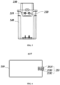
FIG. 4 andFIG. 5 show that anotch portion 251 is provided at where the upper sealingbody 230 and thelower sealing body 240 are engaged, and allows a wire connected to thevacuum pump 100 to pass through. In order to ensure the sealing performance of the sealedbox 200, a snap-fittable sealing ring 253 is provided at thenotch portion 251. The sealingring 253 is made of an elastic material and integrally formed with thegasket ring 250. - Referring to
FIG. 6 andFIG. 7 , the sealingring 253 is composed of two H-shaped members that are flexibly connected, and the H-shaped members can be snap-fitted to each other to form a mounted state that cooperates with thenotch portion 251. The H-shaped member has afirst arm 2531 and asecond arm 2532 parallel to each other, and a connectingportion 2533 connecting thefirst arm 2531 with thesecond arm 2532. Thefirst arm 2531 and thesecond arm 2532 can cooperate to clamp the side wall of the box body at the edge of thenotch portion 251 therebetween to prevent thesealing ring 253 from falling off from thenotch portion 251. The connectingportion 2533 passes through the notch portion and connects thefirst arm 2531 with thesecond arm 2532. The connectingportion 2533 has a recessed arc-shaped surface. When the H-shaped members are snap-fitted to each other, their arc-shaped surfaces together enclose to form a hollow cavity to allow the wire to pass therethrough. - In a case where a plurality of wires passes through the
notch portion 251, if the wires as a whole pass through thenotch portion 251, since the cross section of the wires is circular, a gap formed between the wires will reduce the sealing performance. In this case, the arc-shaped surface of the connectingportion 2533 may be wavy (not shown) to form a plurality of independent hollow cavities in the mounted state to better seal the wires with a circular cross-section. - Referring to
FIG. 8 , a plurality of metal plates 260 are disposed in the sealedbox 200, and the metal plates 260 are disposed between thevacuum pump 100 and the side walls of the sealedbox 200. Since the metal plates 260 have a high density, they can block transmission of sound therethrough and achieve an effect of sound insulation and noise reduction. - Preferably, the metal plate 260 is an aluminum plate, a steel plate, or a galvanized plate.
- Referring to
FIG. 8 andFIG. 9 , in an embodiment of the present invention, there are two metal plates 260 which are respectively attached to two opposite walls of the sealedbox 200. Thelower sealing body 240 and theupper sealing body 230 are respectively provided with a limiting structure to secure themetal plates -
FIG. 8 shows that the bottom wall of thelower sealing body 240 is provided with afirst rib 242 being parallel to aside wall 241 and spaced apart a distance d, and asecond rib 244 being parallel to aside wall 243 and spaced apart a distance D, wherein theside wall 241 and theside wall 243 are opposed, d is the thickness of themetal plate 260a, and D is the thickness of themetal plate 260b. The spacing between thefirst rib 242 and theside wall 241 forms a limiting groove that limits the horizontal displacement of themetal plate 260a, and the spacing between thesecond rib 244 and theside wall 243 forms a limiting groove that limits the horizontal displacement of themetal plate 260b. - Referring to
FIG. 8 andFIG. 10 , thelower sealing body 240 is further provided with a plurality ofguide grooves 245. Theguide grooves 245 extend in a vertical direction and the extension direction is consistent with the insertion direction installing the metal plates 260. Theguide grooves 245 guide the metal plates 260 to be mounted to preset positions. -
FIG. 9 shows that theupper sealing body 230 is provided with a plurality of resistingmembers 231. When theupper sealing body 230 and thelower sealing body 240 are snap-fitted, the resistingmember 231 againsts the top of the metal plate 260. A steppedportion 2311 is provided at an end of the resistingmember 231 which is in contact with the metal plate 260.The steppedportion 2311 cooperates with the side walls of theupper sealing body 230 to form an inverted U-shaped space to accommodate the top of the metal plate 260. The top surface of the steppedportion 2311 againsts the top surface of the metal plate 260 and limits the displacement of the metal plate 260 in the vertical direction. The sides of the stepped portion abut against the sides of the metal plate 260 and limit the displacement of the metal plate 260 in the horizontal direction. - The metal plate 260 is disposed close to the side wall of the sealed
box 200. The vibration of thevacuum pump 100 might cause resonance of the metal plate 260 to form new noise which is conducted externally through the walls of the sealedbox 200. The above limiting structures strictly limit the position of the metal plates 260 to avoid resonating and generating noise. - In an embodiment of the present invention, a
notch portion 251 is disposed on one of theupper sealing body 230 andlower sealing body 240, or on an engagement portion of theupper sealing body 230 andlower sealing body 240, to allow an air pipe assembly to pass therethrough. -
FIG. 10 andFIG. 11 exemplarily show a case where thenotch portion 251 is provided on thelower sealing body 240. Thenotch portion 251 is provided on a side wall of thelower sealing body 240 close to the upper edge, and a groove is provided at peripheral edge of thenotch portion 251 to receive asealing unit 270 to ensure the airtightness of the sealedbox 200. The sealingunit 270 has an annular structure made of an elastic material. - The air pipe assembly comprises an
air inlet pipe 210, anair outlet pipe 220 and a base plate that are integrally formed. Theair inlet pipe 210 and theair outlet pipe 220 are disposed through the base plate, and an outer edge of the base plate matches the shape of thenotch portion 251. A groove is provided on the outer edge of the base plate to mate with a flange on the periphery of thenotch portion 251, the mating of the groove and the flange can clamp and secure the base plate to the notch portion, and thesealing unit 270 is embedded at a gap between the groove and the flange. - The space of the cavity for receiving the
vacuum pump 100 is compact and does not facilitate the operation of connecting and passing the air pipe line. It is possible to, by setting the air pipe assembly as an embedded mounting structure, conveniently embed and secure the air pipe assembly in thenotch portion 251 after the air pipe assembly is connected with thevacuum pump 100, and then snap-fit theupper sealing body 230 and thelower sealing body 240 to complete the assembling. - The gas from the
air outlet pipe 220 is exhausted to the outside of the refrigerator after being silenced. Referring toFIG. 1 andFIG. 12 , in an embodiment of the present invention, thevacuum pump 100 is connected to themuffler 300 through theair outlet pipe 220. Themuffler 300 comprises a housing. The housing is enclosed jointly by a firstbottom surface 310 at a proximal end, a secondbottom surface 320 at a distal end and aside wall 330 connecting the firstbottom surface 310 with the secondbottom surface 320 to form a cylindrical hollow cavity. Themuffler 300 is provided at the proximal end with anair inlet 340 connected to theair outlet pipe 220, and provided with anair outlet 350 at the distal end. The interior of the cavity is divided into several chambers in an axial direction, the axial direction is the direction from theair inlet 340 to theair outlet 350, and at least part of the chambers have different volumes to correspondingly remove sounds at different frequency bands. Exemplarily, the volumes of respective chambers gradually decrease in the axial direction. - Preferably, there are three chambers, which are a
first chamber 361, anintermediate chamber 362 and asecond chamber 363 in turn from the proximal end to the distal end. Thefirst chamber 361 is adjacent to the firstbottom surface 310, thesecond chamber 363 is adjacent to the secondbottom surface 320, and theintermediate cavity 362 is located between thefirst chamber 361 and thesecond chamber 363. Afirst duct 371 is communicated with theair inlet 340 and theintermediate chamber 362, asecond duct 372 is communicated with theintermediate chamber 362 and thesecond chamber 363, athird duct 373 is communicated with thefirst chamber 361 and thesecond chamber 363, and afourth duct 374 is communicated with thefirst chamber 361 and theair outlet 350. - There may be a plurality of
intermediate chambers 362. - Sound waves from the
vacuum pump 100 pass through thefirst duct 371, thesecond duct 372, thethird duct 373 and thefourth duct 374 in turn along with the airflow, and are reflected and refracted in turn in theintermediate chamber 362, thesecond chamber 363 and thefirst chamber 361 which have different volumes, and their energy is gradually dissipated. The muffling frequencies corresponding to thefirst chamber 361, theintermediate chamber 362 and thesecond chamber 363 are a low frequency, a medium frequency and a high frequency. In addition, thefirst duct 371, thesecond duct 372, thethird duct 373 and thefourth duct 374 are provided with narrow inner diameters, so that partial energy of the sound waves is converted into thermal energy and dissipated when the sound waves pass through the ducts. - The muffler is arranged in a way that the sound waves travel in a path as long as possible in the muffler to reduce the energy and are reflected and refracted in different chambers, and a better muffling effect is achieved with a smaller muffler axial distance.
- Referring to
FIG. 13 , in a further embodiment of the present invention, themuffler 400 comprises a housing. The housing is enclosed jointly by a firstbottom surface 410 at a proximal end, a secondbottom surface 420 at a distal end, and aside wall 430 connecting the firstbottom surface 410 with the secondbottom surface 420 to form a cylindrical hollow cavity. A single chamber is formed in the cavity. Themuffler 400 is provided with anair inlet 440 connected to theair outlet pipe 220 at the proximal end, and anair outlet 450 provided at the distal end. Afirst duct 471 is communicated with theair inlet 440 and the chamber, and a distal end of thefirst duct 471 is adjacent to the secondbottom surface 420. Asecond duct 472 is communicated with the chamber and theair outlet 450, and a proximal end of thesecond duct 472 is adjacent to the firstbottom surface 420. - The sound waves are reflected and refracted in the chamber, and the energy is gradually dissipated. The length of the
first duct 471 and thesecond duct 472 is a quarter of a wavelength of a target audio to specifically eliminate the sound of the target audio. Preferably, a frequency of the target audio is 1000Hz. - The
first duct 471 and thesecond duct 472 are provided with narrow inner diameters, so that partial energy of the sound waves is converted into thermal energy and dissipated when the sound waves pass through the ducts. - In the noise generated by the
vacuum pump 100 and conducted via gas, the high-frequency noise cannot be heard by human ears, and the noise causing interference to the user is mainly low-frequency noise. The present embodiment may purposefully eliminate low-frequency noise and make the structure of the muffler simpler. - Referring to
FIG. 14 andFIG. 15 , in a further embodiment of the present invention, themuffler 500 is disposed inside the sealedbox 200, and connects the exhaust line of thevacuum pump 100 and theair outlet pipe 220. Themuffler 500 comprises a housing, and the housing is enclosed to form a hollow cavity for refraction and reflection of sound waves. The hollow cavity comprises acylindrical chamber 510 and arectangular parallelepiped chamber 520. One of bottom surfaces of thecylindrical chamber 510 is connected to onesurface 521 of therectangular parallelepiped chamber 520. Thecylindrical chamber 510 is communicated with the interior of therectangular parallelepiped chamber 520. - The diameter of the bottom surface of the
cylindrical chamber 510 is less than or equal to a length of a side of a connectingsurface 521 of therectangular parallelepiped chamber 520. - The
cylinder chamber 510 of themuffler 500 is provided with anair inlet 540 and anair outlet 550, and theair inlet 540 and theair outlet 550 are arranged at an angle so that the gas entering the hollow cavity reaches the outlet through reflected and refracted. During the process, the energy loses to achieve the muffling purpose. - The
air inlet 540 is disposed on thebottom surface 511 of thecylindrical chamber 510, and theair outlet 550 is disposed on a side of thecylindrical chamber 510. - The inner diameters of the
air inlet 540 and theair outlet 550 are the same, so that the pressures at the two ports are balanced. - In the present embodiment, through the change of the shape of the hollow cavity, the sound waves are enabled to be reflected and refracted irregularly, and the energy is dissipated.
- Referring to
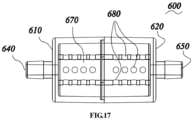
FIG. 16 andFIG. 17 , in a further embodiment of the present invention, amuffler 600 comprises a housing, and the housing is enclosed to form a hollow cavity. Themuffler 600 is provided with anair inlet 640 at a proximal end and anair outlet 650 at a distal end. Theair inlet 640 and theair outlet 650 are communicated by aduct 670 provided in the housing. Theduct 670 and the housing form a sleeve structure. Theduct 670 is filled with a medium to absorb the vibrational energy of the sound waves and weaken the sound intensity. Furthermore, the medium is silencer cotton. - A plurality of through
holes 680 are defined on the side wall of theduct 670, so that theduct 670 can implement communication with the cavity. The throughholes 680 are distributed spaced apart in a circumferential direction of the sidewall of theduct 670, that is, theduct 670 defines through holes in a plurality of directions. - Preferably, the housing is enclosed jointly by a first
bottom surface 610 at a proximal end, a secondbottom surface 620 at a distal end, and aside wall 630 connecting the firstbottom surface 610 with the secondbottom surface 620 to form a cylindrical hollow cavity. The firstbottom surface 610 is provided with anair inlet 640, and the secondbottom surface 620 is provided with anair outlet 650. - Preferably, a diameter of the through holes is less than 1 mm.
- Preferably, the cavity enclosed by the housing is divided into several chambers arranged from the proximal end to the distal end.
- The sound waves from the
vacuum pump 100 enter theduct 670 from theair inlet 640, and reach theair outlet 650 after being silenced by the medium. The sound waves at a specific frequency are attenuated and the sound intensity is weakened. During this process, partial sound waves, being diffracted by the throughholes 680, enter the cavity, and are further attenuated after being refracted and reflected in the cavity. - The muffler is arranged in a way that the sound intensity is reduced through multiple channels by combining medium sound reduction with cavity sound reduction and be employing small holes to implement sound wave diffraction.
- It should be understood that although the description is described according to the embodiments, not every embodiment only comprises one independent technical solution, that such a description manner is only for the sake of clarity, that those skilled in the art should take the description as an integral part, and that the technical solutions in the embodiments may be suitably combined to form other embodiments understandable by those skilled in the art.
- The detailed descriptions set forth above are merely specific illustrations of feasible embodiments of the present invention, and are not intended to limit the scope of protection of the present invention.
Claims (8)
- A muffler (500), comprising a housing enclosed to form a hollow cavity, the cavity comprises a cylindrical chamber (510) and a rectangular parallelepiped chamber (520), the cylindrical chamber comprising two opposing bottom surfaces and a side surface joining the two bottom surfaces, wherein one of the bottom surfaces of the cylindrical chamber (510) is connected with a first surface (521) of the rectangular parallelepiped chamber (520), the cylindrical chamber (510) communicates with an interior of the rectangular parallelepiped chamber(520), and the cylindrical chamber (510) is provided with an air inlet (540) and an air outlet (550);the air inlet (540) and the air outlet (550) are arranged at an angle; whereinthe air inlet (540) is provided on the other bottom surface (511) of the cylindrical chamber (510), characterized in thatthe air outlet (550) is provided on the side surface of the cylindrical chamber (510).
- The muffler (500) according to claim 1, wherein a diameter of the bottom surface (511) of the cylindrical chamber (510) is smaller than or equal to a length of a side of the first surface (521).
- The muffler (500) according to claim 1, wherein inner diameters of the air inlet (540) and the air outlet (550) are the same.
- A refrigerator vacuum assembly, comprising a sealed box (200), wherein,the sealed box (200) comprises an upper sealing body (230) and a lower sealing body (240), and the upper sealing body (230) and the lower sealing body (240) can be snap-fitted to define a receiving cavity;a vacuum pump (100) is arranged in the receiving cavity, and the vacuum pump (100) is connected with the muffler (500) according to any one of claims 1-3.
- The refrigerator vacuum assembly according to claim 4, wherein further comprises an air outlet pipe (220) passing through the sealed box (200), the air inlet (540) of the muffler (500) is connected with the vacuum pump (100), and the air outlet (550) is connected with the air outlet pipe (220).
- The refrigerator vacuum assembly according to claim 4, wherein a notch portion (251) is provided where the upper sealing body (230) engages the lower sealing body (240), the vacuum assembly further comprises a seal (253) capable of being embedded in the notch portion (251), the seal (253) comprises a snap-fittable portion which is composed of two H-shaped members that are flexibly connected, the two H-shaped members can be snap-fitted to each other to form a mounted state, and the H-shaped member has a first arm (2531) and a second arm (2532) which are parallel to each other, and a connecting portion (2533) connecting the first arm (2531) with the second arm (2532), the connecting portion (2533) has an arc-shaped surface, and arc-shaped surfaces of the two H-shaped members jointly enclose to form a hollow cavity when the H-shaped members are in the mounted state.
- The refrigerator vacuum assembly according to claim 6, wherein the two H-shaped members match the shape of the notch portion (251) in the mounted state.
- A refrigerator, comprising a sealed box (200) receiving a vacuum pump (100), wherein the refrigerator further comprises the muffler (500) according to claim 1, and the muffler (500) is disposed in the sealed box (200) and connected with the vacuum pump (100).
Applications Claiming Priority (2)
| Application Number | Priority Date | Filing Date | Title |
|---|---|---|---|
| CN201711310071.1A CN108150388B (en) | 2017-12-11 | 2017-12-11 | Cavity silencers and refrigerators |
| PCT/CN2018/119776 WO2019114627A1 (en) | 2017-12-11 | 2018-12-07 | Cavity silencer and refrigerator |
Publications (4)
| Publication Number | Publication Date |
|---|---|
| EP3726168A1 EP3726168A1 (en) | 2020-10-21 |
| EP3726168A4 EP3726168A4 (en) | 2021-01-13 |
| EP3726168B1 true EP3726168B1 (en) | 2025-04-16 |
| EP3726168C0 EP3726168C0 (en) | 2025-04-16 |
Family
ID=62466868
Family Applications (1)
| Application Number | Title | Priority Date | Filing Date |
|---|---|---|---|
| EP18888045.4A Active EP3726168B1 (en) | 2017-12-11 | 2018-12-07 | Cavity muffler and refrigerator |
Country Status (6)
| Country | Link |
|---|---|
| US (1) | US11549499B2 (en) |
| EP (1) | EP3726168B1 (en) |
| CN (1) | CN108150388B (en) |
| AU (1) | AU2018382027B2 (en) |
| NZ (1) | NZ765281A (en) |
| WO (1) | WO2019114627A1 (en) |
Families Citing this family (7)
| Publication number | Priority date | Publication date | Assignee | Title |
|---|---|---|---|---|
| CN108253701B (en) * | 2017-12-11 | 2020-05-26 | 青岛海尔股份有限公司 | Vacuum assembly and refrigerator with plate-like sound insulation member |
| CN107989774A (en) * | 2017-12-11 | 2018-05-04 | 青岛海尔股份有限公司 | Vacuum pump discharges pipe muffler and refrigerator |
| CN108150388B (en) * | 2017-12-11 | 2020-04-21 | 青岛海尔股份有限公司 | Cavity silencers and refrigerators |
| CN108195126B (en) | 2017-12-11 | 2020-07-24 | 青岛海尔股份有限公司 | Vacuum assembly and refrigerator with integrally formed air duct member |
| CN212006378U (en) * | 2020-04-17 | 2020-11-24 | 海信(山东)冰箱有限公司 | Refrigerator with a door |
| CN212179335U (en) * | 2020-05-11 | 2020-12-18 | 海信(山东)冰箱有限公司 | refrigerator |
| EP4149648A4 (en) * | 2020-05-12 | 2024-05-29 | Solventum Intellectual Properties Company | MEMBRANE SEALING LAYER AND SPACER RING FOR VIRAL CLEARANCE CHROMATOGRAPHY DEVICE |
Citations (1)
| Publication number | Priority date | Publication date | Assignee | Title |
|---|---|---|---|---|
| JPH11193712A (en) * | 1997-10-27 | 1999-07-21 | Hitachi Kasei Techno Plant Kk | Noise and airflow separation type silencer and low noise type equipment using the same |
Family Cites Families (18)
| Publication number | Priority date | Publication date | Assignee | Title |
|---|---|---|---|---|
| JPS5431839A (en) * | 1977-08-15 | 1979-03-08 | Toyota Motor Corp | Muffler for internal combustion engine |
| SE510530C2 (en) * | 1993-03-05 | 1999-05-31 | Volvo Ab | Device for sound attenuation in a duct system |
| KR100269951B1 (en) | 1997-11-05 | 2000-10-16 | 배길성 | Sucking muffler of a compressor |
| JP3922140B2 (en) | 2002-09-06 | 2007-05-30 | 株式会社豊田自動織機 | Fluid pump device |
| CN201218181Y (en) * | 2008-06-11 | 2009-04-08 | 汤建 | Miniature silencing air pump |
| CN101629563A (en) * | 2008-07-18 | 2010-01-20 | 扎努西电气机械天津压缩机有限公司 | Silencer with balancing chamber |
| CN101886624A (en) * | 2010-07-05 | 2010-11-17 | 苏州盟通利机电设备有限公司 | Vacuum pump without pressure difference |
| CN201916031U (en) | 2011-01-17 | 2011-08-03 | 山西华翔投资有限公司 | Muffler for wet vacuum pump |
| CN103644699B (en) * | 2013-12-06 | 2016-06-15 | 南京创维家用电器有限公司 | Vacuum drawer and refrigerator |
| CN104675676B (en) * | 2015-02-05 | 2017-10-31 | 加西贝拉压缩机有限公司 | A kind of air suction structure of refrigeration compressor |
| DE102015211460A1 (en) * | 2015-06-22 | 2016-12-22 | Bayerische Motoren Werke Aktiengesellschaft | exhaust system |
| CN106098051B (en) * | 2016-07-14 | 2020-01-31 | 西安交通大学 | improved Helmholtz silencer and manufacturing method thereof |
| CN106593818B (en) * | 2016-12-02 | 2019-05-03 | 青岛海尔股份有限公司 | Refrigerator and freezer |
| CN107989774A (en) | 2017-12-11 | 2018-05-04 | 青岛海尔股份有限公司 | Vacuum pump discharges pipe muffler and refrigerator |
| CN108195126B (en) | 2017-12-11 | 2020-07-24 | 青岛海尔股份有限公司 | Vacuum assembly and refrigerator with integrally formed air duct member |
| CN108150388B (en) | 2017-12-11 | 2020-04-21 | 青岛海尔股份有限公司 | Cavity silencers and refrigerators |
| CN108131277B (en) | 2017-12-11 | 2021-03-23 | 海尔智家股份有限公司 | Refrigerator vacuum components and refrigerators |
| CN108302008B (en) | 2017-12-11 | 2021-03-23 | 海尔智家股份有限公司 | Refrigerator vacuum components and refrigerators |
-
2017
- 2017-12-11 CN CN201711310071.1A patent/CN108150388B/en active Active
-
2018
- 2018-12-07 AU AU2018382027A patent/AU2018382027B2/en active Active
- 2018-12-07 NZ NZ765281A patent/NZ765281A/en unknown
- 2018-12-07 WO PCT/CN2018/119776 patent/WO2019114627A1/en not_active Ceased
- 2018-12-07 US US16/771,656 patent/US11549499B2/en active Active
- 2018-12-07 EP EP18888045.4A patent/EP3726168B1/en active Active
Patent Citations (1)
| Publication number | Priority date | Publication date | Assignee | Title |
|---|---|---|---|---|
| JPH11193712A (en) * | 1997-10-27 | 1999-07-21 | Hitachi Kasei Techno Plant Kk | Noise and airflow separation type silencer and low noise type equipment using the same |
Also Published As
| Publication number | Publication date |
|---|---|
| NZ765281A (en) | 2022-10-28 |
| WO2019114627A1 (en) | 2019-06-20 |
| US20210071656A1 (en) | 2021-03-11 |
| EP3726168A1 (en) | 2020-10-21 |
| CN108150388A (en) | 2018-06-12 |
| AU2018382027B2 (en) | 2021-07-08 |
| AU2018382027A1 (en) | 2020-06-25 |
| CN108150388B (en) | 2020-04-21 |
| US11549499B2 (en) | 2023-01-10 |
| EP3726168A4 (en) | 2021-01-13 |
| EP3726168C0 (en) | 2025-04-16 |
Similar Documents
| Publication | Publication Date | Title |
|---|---|---|
| AU2018382028B2 (en) | Refrigerator | |
| AU2018382027B2 (en) | Cavity muffler and refrigerator | |
| EP3726055A1 (en) | Vacuum pump vent pipe silencer and refrigerator having same | |
| CN108131277B (en) | Refrigerator vacuum components and refrigerators | |
| US11255597B2 (en) | Refrigerator | |
| JP5404387B2 (en) | Resonator in acoustic muffler for cooling compressor | |
| CN108302008B (en) | Refrigerator vacuum components and refrigerators | |
| JP2008540891A (en) | Suction muffler for cooling compressor | |
| CN108253701B (en) | Vacuum assembly and refrigerator with plate-like sound insulation member | |
| CN113757124B (en) | Compressors and refrigeration equipment |
Legal Events
| Date | Code | Title | Description |
|---|---|---|---|
| STAA | Information on the status of an ep patent application or granted ep patent |
Free format text: STATUS: THE INTERNATIONAL PUBLICATION HAS BEEN MADE |
|
| PUAI | Public reference made under article 153(3) epc to a published international application that has entered the european phase |
Free format text: ORIGINAL CODE: 0009012 |
|
| STAA | Information on the status of an ep patent application or granted ep patent |
Free format text: STATUS: REQUEST FOR EXAMINATION WAS MADE |
|
| 17P | Request for examination filed |
Effective date: 20200327 |
|
| AK | Designated contracting states |
Kind code of ref document: A1 Designated state(s): AL AT BE BG CH CY CZ DE DK EE ES FI FR GB GR HR HU IE IS IT LI LT LU LV MC MK MT NL NO PL PT RO RS SE SI SK SM TR |
|
| AX | Request for extension of the european patent |
Extension state: BA ME |
|
| REG | Reference to a national code |
Ref country code: DE Ref legal event code: R079 Free format text: PREVIOUS MAIN CLASS: F25D0023000000 Ipc: F04B0039000000 |
|
| A4 | Supplementary search report drawn up and despatched |
Effective date: 20201215 |
|
| RIC1 | Information provided on ipc code assigned before grant |
Ipc: F04B 39/00 20060101AFI20201209BHEP Ipc: F25D 23/00 20060101ALN20201209BHEP Ipc: G10K 11/172 20060101ALI20201209BHEP Ipc: F25D 17/04 20060101ALI20201209BHEP |
|
| DAV | Request for validation of the european patent (deleted) | ||
| DAX | Request for extension of the european patent (deleted) | ||
| STAA | Information on the status of an ep patent application or granted ep patent |
Free format text: STATUS: EXAMINATION IS IN PROGRESS |
|
| 17Q | First examination report despatched |
Effective date: 20230118 |
|
| GRAP | Despatch of communication of intention to grant a patent |
Free format text: ORIGINAL CODE: EPIDOSNIGR1 |
|
| STAA | Information on the status of an ep patent application or granted ep patent |
Free format text: STATUS: GRANT OF PATENT IS INTENDED |
|
| RIC1 | Information provided on ipc code assigned before grant |
Ipc: F25D 23/00 20060101ALN20241028BHEP Ipc: F25D 17/04 20060101ALI20241028BHEP Ipc: G10K 11/172 20060101ALI20241028BHEP Ipc: F04B 39/00 20060101AFI20241028BHEP |
|
| INTG | Intention to grant announced |
Effective date: 20241112 |
|
| GRAS | Grant fee paid |
Free format text: ORIGINAL CODE: EPIDOSNIGR3 |
|
| GRAA | (expected) grant |
Free format text: ORIGINAL CODE: 0009210 |
|
| STAA | Information on the status of an ep patent application or granted ep patent |
Free format text: STATUS: THE PATENT HAS BEEN GRANTED |
|
| AK | Designated contracting states |
Kind code of ref document: B1 Designated state(s): AL AT BE BG CH CY CZ DE DK EE ES FI FR GB GR HR HU IE IS IT LI LT LU LV MC MK MT NL NO PL PT RO RS SE SI SK SM TR |
|
| REG | Reference to a national code |
Ref country code: GB Ref legal event code: FG4D |
|
| REG | Reference to a national code |
Ref country code: CH Ref legal event code: EP Ref country code: DE Ref legal event code: R096 Ref document number: 602018081214 Country of ref document: DE |
|
| REG | Reference to a national code |
Ref country code: IE Ref legal event code: FG4D |
|
| U01 | Request for unitary effect filed |
Effective date: 20250513 |
|
| U07 | Unitary effect registered |
Designated state(s): AT BE BG DE DK EE FI FR IT LT LU LV MT NL PT RO SE SI Effective date: 20250519 |
|
| PG25 | Lapsed in a contracting state [announced via postgrant information from national office to epo] |
Ref country code: ES Free format text: LAPSE BECAUSE OF FAILURE TO SUBMIT A TRANSLATION OF THE DESCRIPTION OR TO PAY THE FEE WITHIN THE PRESCRIBED TIME-LIMIT Effective date: 20250416 |
|
| PG25 | Lapsed in a contracting state [announced via postgrant information from national office to epo] |
Ref country code: GR Free format text: LAPSE BECAUSE OF FAILURE TO SUBMIT A TRANSLATION OF THE DESCRIPTION OR TO PAY THE FEE WITHIN THE PRESCRIBED TIME-LIMIT Effective date: 20250717 Ref country code: NO Free format text: LAPSE BECAUSE OF FAILURE TO SUBMIT A TRANSLATION OF THE DESCRIPTION OR TO PAY THE FEE WITHIN THE PRESCRIBED TIME-LIMIT Effective date: 20250716 |
|
| PG25 | Lapsed in a contracting state [announced via postgrant information from national office to epo] |
Ref country code: PL Free format text: LAPSE BECAUSE OF FAILURE TO SUBMIT A TRANSLATION OF THE DESCRIPTION OR TO PAY THE FEE WITHIN THE PRESCRIBED TIME-LIMIT Effective date: 20250416 |
|
| PG25 | Lapsed in a contracting state [announced via postgrant information from national office to epo] |
Ref country code: HR Free format text: LAPSE BECAUSE OF FAILURE TO SUBMIT A TRANSLATION OF THE DESCRIPTION OR TO PAY THE FEE WITHIN THE PRESCRIBED TIME-LIMIT Effective date: 20250416 |
|
| PG25 | Lapsed in a contracting state [announced via postgrant information from national office to epo] |
Ref country code: RS Free format text: LAPSE BECAUSE OF FAILURE TO SUBMIT A TRANSLATION OF THE DESCRIPTION OR TO PAY THE FEE WITHIN THE PRESCRIBED TIME-LIMIT Effective date: 20250716 |
|
| PG25 | Lapsed in a contracting state [announced via postgrant information from national office to epo] |
Ref country code: IS Free format text: LAPSE BECAUSE OF FAILURE TO SUBMIT A TRANSLATION OF THE DESCRIPTION OR TO PAY THE FEE WITHIN THE PRESCRIBED TIME-LIMIT Effective date: 20250816 |
|
| U20 | Renewal fee for the european patent with unitary effect paid |
Year of fee payment: 8 Effective date: 20251127 |
|
| PG25 | Lapsed in a contracting state [announced via postgrant information from national office to epo] |
Ref country code: SM Free format text: LAPSE BECAUSE OF FAILURE TO SUBMIT A TRANSLATION OF THE DESCRIPTION OR TO PAY THE FEE WITHIN THE PRESCRIBED TIME-LIMIT Effective date: 20250416 |
|
| PG25 | Lapsed in a contracting state [announced via postgrant information from national office to epo] |
Ref country code: CZ Free format text: LAPSE BECAUSE OF FAILURE TO SUBMIT A TRANSLATION OF THE DESCRIPTION OR TO PAY THE FEE WITHIN THE PRESCRIBED TIME-LIMIT Effective date: 20250416 |
|
| PG25 | Lapsed in a contracting state [announced via postgrant information from national office to epo] |
Ref country code: SK Free format text: LAPSE BECAUSE OF FAILURE TO SUBMIT A TRANSLATION OF THE DESCRIPTION OR TO PAY THE FEE WITHIN THE PRESCRIBED TIME-LIMIT Effective date: 20250416 |
|
| PLBE | No opposition filed within time limit |
Free format text: ORIGINAL CODE: 0009261 |
|
| STAA | Information on the status of an ep patent application or granted ep patent |
Free format text: STATUS: NO OPPOSITION FILED WITHIN TIME LIMIT |
|
| REG | Reference to a national code |
Ref country code: CH Ref legal event code: L10 Free format text: ST27 STATUS EVENT CODE: U-0-0-L10-L00 (AS PROVIDED BY THE NATIONAL OFFICE) Effective date: 20260225 |
|
| 26N | No opposition filed |
Effective date: 20260119 |