EP3726095B1 - Multispeed transmission - Google Patents
Multispeed transmission Download PDFInfo
- Publication number
- EP3726095B1 EP3726095B1 EP19209843.2A EP19209843A EP3726095B1 EP 3726095 B1 EP3726095 B1 EP 3726095B1 EP 19209843 A EP19209843 A EP 19209843A EP 3726095 B1 EP3726095 B1 EP 3726095B1
- Authority
- EP
- European Patent Office
- Prior art keywords
- shaft
- clutch
- gear
- input
- clutch shaft
- Prior art date
- Legal status (The legal status is an assumption and is not a legal conclusion. Google has not performed a legal analysis and makes no representation as to the accuracy of the status listed.)
- Active
Links
Images




Classifications
-
- F—MECHANICAL ENGINEERING; LIGHTING; HEATING; WEAPONS; BLASTING
- F16—ENGINEERING ELEMENTS AND UNITS; GENERAL MEASURES FOR PRODUCING AND MAINTAINING EFFECTIVE FUNCTIONING OF MACHINES OR INSTALLATIONS; THERMAL INSULATION IN GENERAL
- F16H—GEARING
- F16H3/00—Toothed gearings for conveying rotary motion with variable gear ratio or for reversing rotary motion
- F16H3/02—Toothed gearings for conveying rotary motion with variable gear ratio or for reversing rotary motion without gears having orbital motion
- F16H3/08—Toothed gearings for conveying rotary motion with variable gear ratio or for reversing rotary motion without gears having orbital motion exclusively or essentially with continuously meshing gears, that can be disengaged from their shafts
- F16H3/087—Toothed gearings for conveying rotary motion with variable gear ratio or for reversing rotary motion without gears having orbital motion exclusively or essentially with continuously meshing gears, that can be disengaged from their shafts characterised by the disposition of the gears
- F16H3/093—Toothed gearings for conveying rotary motion with variable gear ratio or for reversing rotary motion without gears having orbital motion exclusively or essentially with continuously meshing gears, that can be disengaged from their shafts characterised by the disposition of the gears with two or more countershafts
- F16H3/097—Toothed gearings for conveying rotary motion with variable gear ratio or for reversing rotary motion without gears having orbital motion exclusively or essentially with continuously meshing gears, that can be disengaged from their shafts characterised by the disposition of the gears with two or more countershafts the input and output shafts being aligned on the same axis
-
- F—MECHANICAL ENGINEERING; LIGHTING; HEATING; WEAPONS; BLASTING
- F16—ENGINEERING ELEMENTS AND UNITS; GENERAL MEASURES FOR PRODUCING AND MAINTAINING EFFECTIVE FUNCTIONING OF MACHINES OR INSTALLATIONS; THERMAL INSULATION IN GENERAL
- F16H—GEARING
- F16H3/00—Toothed gearings for conveying rotary motion with variable gear ratio or for reversing rotary motion
- F16H3/02—Toothed gearings for conveying rotary motion with variable gear ratio or for reversing rotary motion without gears having orbital motion
- F16H3/08—Toothed gearings for conveying rotary motion with variable gear ratio or for reversing rotary motion without gears having orbital motion exclusively or essentially with continuously meshing gears, that can be disengaged from their shafts
- F16H3/087—Toothed gearings for conveying rotary motion with variable gear ratio or for reversing rotary motion without gears having orbital motion exclusively or essentially with continuously meshing gears, that can be disengaged from their shafts characterised by the disposition of the gears
- F16H3/093—Toothed gearings for conveying rotary motion with variable gear ratio or for reversing rotary motion without gears having orbital motion exclusively or essentially with continuously meshing gears, that can be disengaged from their shafts characterised by the disposition of the gears with two or more countershafts
-
- F—MECHANICAL ENGINEERING; LIGHTING; HEATING; WEAPONS; BLASTING
- F02—COMBUSTION ENGINES; HOT-GAS OR COMBUSTION-PRODUCT ENGINE PLANTS
- F02C—GAS-TURBINE PLANTS; AIR INTAKES FOR JET-PROPULSION PLANTS; CONTROLLING FUEL SUPPLY IN AIR-BREATHING JET-PROPULSION PLANTS
- F02C7/00—Features, components parts, details or accessories, not provided for in, or of interest apart form groups F02C1/00 - F02C6/00; Air intakes for jet-propulsion plants
- F02C7/32—Arrangement, mounting, or driving, of auxiliaries
-
- F—MECHANICAL ENGINEERING; LIGHTING; HEATING; WEAPONS; BLASTING
- F16—ENGINEERING ELEMENTS AND UNITS; GENERAL MEASURES FOR PRODUCING AND MAINTAINING EFFECTIVE FUNCTIONING OF MACHINES OR INSTALLATIONS; THERMAL INSULATION IN GENERAL
- F16H—GEARING
- F16H3/00—Toothed gearings for conveying rotary motion with variable gear ratio or for reversing rotary motion
- F16H3/006—Toothed gearings for conveying rotary motion with variable gear ratio or for reversing rotary motion power being selectively transmitted by parallel flow paths, e.g. dual clutch transmissions
-
- F—MECHANICAL ENGINEERING; LIGHTING; HEATING; WEAPONS; BLASTING
- F16—ENGINEERING ELEMENTS AND UNITS; GENERAL MEASURES FOR PRODUCING AND MAINTAINING EFFECTIVE FUNCTIONING OF MACHINES OR INSTALLATIONS; THERMAL INSULATION IN GENERAL
- F16H—GEARING
- F16H3/00—Toothed gearings for conveying rotary motion with variable gear ratio or for reversing rotary motion
- F16H3/02—Toothed gearings for conveying rotary motion with variable gear ratio or for reversing rotary motion without gears having orbital motion
- F16H3/08—Toothed gearings for conveying rotary motion with variable gear ratio or for reversing rotary motion without gears having orbital motion exclusively or essentially with continuously meshing gears, that can be disengaged from their shafts
- F16H3/10—Toothed gearings for conveying rotary motion with variable gear ratio or for reversing rotary motion without gears having orbital motion exclusively or essentially with continuously meshing gears, that can be disengaged from their shafts with one or more one-way clutches as an essential feature
-
- F—MECHANICAL ENGINEERING; LIGHTING; HEATING; WEAPONS; BLASTING
- F05—INDEXING SCHEMES RELATING TO ENGINES OR PUMPS IN VARIOUS SUBCLASSES OF CLASSES F01-F04
- F05D—INDEXING SCHEME FOR ASPECTS RELATING TO NON-POSITIVE-DISPLACEMENT MACHINES OR ENGINES, GAS-TURBINES OR JET-PROPULSION PLANTS
- F05D2260/00—Function
- F05D2260/40—Transmission of power
- F05D2260/403—Transmission of power through the shape of the drive components
- F05D2260/4031—Transmission of power through the shape of the drive components as in toothed gearing
-
- F—MECHANICAL ENGINEERING; LIGHTING; HEATING; WEAPONS; BLASTING
- F16—ENGINEERING ELEMENTS AND UNITS; GENERAL MEASURES FOR PRODUCING AND MAINTAINING EFFECTIVE FUNCTIONING OF MACHINES OR INSTALLATIONS; THERMAL INSULATION IN GENERAL
- F16H—GEARING
- F16H3/00—Toothed gearings for conveying rotary motion with variable gear ratio or for reversing rotary motion
- F16H3/02—Toothed gearings for conveying rotary motion with variable gear ratio or for reversing rotary motion without gears having orbital motion
- F16H3/08—Toothed gearings for conveying rotary motion with variable gear ratio or for reversing rotary motion without gears having orbital motion exclusively or essentially with continuously meshing gears, that can be disengaged from their shafts
- F16H2003/0818—Toothed gearings for conveying rotary motion with variable gear ratio or for reversing rotary motion without gears having orbital motion exclusively or essentially with continuously meshing gears, that can be disengaged from their shafts comprising means for power-shifting
-
- F—MECHANICAL ENGINEERING; LIGHTING; HEATING; WEAPONS; BLASTING
- F16—ENGINEERING ELEMENTS AND UNITS; GENERAL MEASURES FOR PRODUCING AND MAINTAINING EFFECTIVE FUNCTIONING OF MACHINES OR INSTALLATIONS; THERMAL INSULATION IN GENERAL
- F16H—GEARING
- F16H3/00—Toothed gearings for conveying rotary motion with variable gear ratio or for reversing rotary motion
- F16H3/02—Toothed gearings for conveying rotary motion with variable gear ratio or for reversing rotary motion without gears having orbital motion
- F16H3/08—Toothed gearings for conveying rotary motion with variable gear ratio or for reversing rotary motion without gears having orbital motion exclusively or essentially with continuously meshing gears, that can be disengaged from their shafts
- F16H3/087—Toothed gearings for conveying rotary motion with variable gear ratio or for reversing rotary motion without gears having orbital motion exclusively or essentially with continuously meshing gears, that can be disengaged from their shafts characterised by the disposition of the gears
- F16H3/093—Toothed gearings for conveying rotary motion with variable gear ratio or for reversing rotary motion without gears having orbital motion exclusively or essentially with continuously meshing gears, that can be disengaged from their shafts characterised by the disposition of the gears with two or more countershafts
- F16H2003/0931—Toothed gearings for conveying rotary motion with variable gear ratio or for reversing rotary motion without gears having orbital motion exclusively or essentially with continuously meshing gears, that can be disengaged from their shafts characterised by the disposition of the gears with two or more countershafts each countershaft having an output gear meshing with a single common gear on the output shaft
-
- F—MECHANICAL ENGINEERING; LIGHTING; HEATING; WEAPONS; BLASTING
- F16—ENGINEERING ELEMENTS AND UNITS; GENERAL MEASURES FOR PRODUCING AND MAINTAINING EFFECTIVE FUNCTIONING OF MACHINES OR INSTALLATIONS; THERMAL INSULATION IN GENERAL
- F16H—GEARING
- F16H2200/00—Transmissions for multiple ratios
- F16H2200/003—Transmissions for multiple ratios characterised by the number of forward speeds
- F16H2200/0039—Transmissions for multiple ratios characterised by the number of forward speeds the gear ratios comprising three forward speeds
-
- F—MECHANICAL ENGINEERING; LIGHTING; HEATING; WEAPONS; BLASTING
- F16—ENGINEERING ELEMENTS AND UNITS; GENERAL MEASURES FOR PRODUCING AND MAINTAINING EFFECTIVE FUNCTIONING OF MACHINES OR INSTALLATIONS; THERMAL INSULATION IN GENERAL
- F16H—GEARING
- F16H2200/00—Transmissions for multiple ratios
- F16H2200/003—Transmissions for multiple ratios characterised by the number of forward speeds
- F16H2200/0043—Transmissions for multiple ratios characterised by the number of forward speeds the gear ratios comprising four forward speeds
Definitions
- This invention relates to transmissions, more specifically to multispeed transmission systems, e.g., for low speed spool turbomachine engines.
- Moving turbomachine engine accessories to the low speed spool requires a speed converting transmission to take a wide speed range and convert it into a narrow speed range.
- One method of doing this is the use of a shifting transmission consisting of clutches that selectively engage different gear ratios.
- a multispeed turbomachine transmission according to the invention is defined by claim 1 Preferred embodiments are shown in the dependent claims.
- a method for controlling such a transmission is defined by claim 11.
- an aircraft turbomachine low speed spool transmission is defined by claim 12.
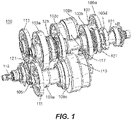
- Fig. 1 For purposes of explanation and illustration, and not limitation, an illustrative view of an embodiment of a transmission in accordance with the invention is shown in Fig. 1 and is designated generally by reference character 100. Other embodiments and/or aspects of this invention are shown in Figs. 2-12 .
- a multispeed turbomachine transmission 100 can include an input shaft 101 and a plurality of input shaft gears 103a, 103b, 103c, 103d disposed on the input shaft 101.
- the transmission 100 can include one or more clutch shafts 105, 107.
- the transmission 100 can include one or more clutch shaft input gears 109a, 109b, 109c, 109d disposed on the one or more clutch shafts 105, 107, each meshed with at least one of the plurality of input shaft gears 103a, 103b, 103c, 103d, e.g., meshed respectively as shown.
- the transmission 100 can include at least one clutch shaft output gear 111, 113 mounted to each clutch shaft 105, 107, e.g., respectively as shown.
- the transmission 100 can include a clutch 115, 117 connected to each clutch shaft 105, 107, e.g., respectively as shown. Any suitable number of clutches is contemplated herein. Any suitable type of clutch is contemplated herein.
- one or more clutches 115, 117 can include a hydraulically actuated clutch, a mechanically actuated clutch, a wet clutch, a piston/friction disc clutch, and/or any combination thereof or having any other suitable characteristics.
- Each clutch 115, 117 can be configured to selectively connect the one or more clutch shaft input gears 109a, 109b, 109c, 109d to the at least one clutch shaft output gear 111, 113 (e.g., by engaging the one or more clutch shaft input gears 109a, 109b, 109c, 109d to a respective clutch shaft 105, 107.
- the transmission 100 can include an output shaft 119 and at least one output shaft gear 121 connected to the output shaft 119 and meshed with the at least one clutch shaft output gear 111, 113. Any other output shaft arrangement is contemplated herein.
- one or more of the plurality of input shaft gears 103a, 103b, 103c can be rotatably mounted (e.g., via one or more bearings 123) to the input shaft 101 to be able to rotate relative to the input shaft 101.
- One or more synchronizers 125, 127 can be disposed on the input shaft 101 and can be configured to selectively connect one or more of the plurality of input shaft gears 103a, 103b, 103c to the input shaft 101 such that the input shaft gears 103a, 103b, 103c rotate with the input shaft 101.
- the one or more synchronizers 125, 127 can include at least one synchromesh, e.g., as shown, for example.
- the synchronizers 125, 127 can include a sliding collar 129a (e.g., splined to a member 129b that is attached to and rotates with the input shaft 101), one or more synchro rings 129c configured to be engaged by sliding collar 129a, and one or more friction cones 129d, each attached to a respective input shaft gear 103a, 103b, 103c and configured to be frictionally engaged by a synchro ring 129c to cause the input shaft gear 103a, 103b, 103c to be synchronized in speed with the input shaft 101.
- a sliding collar 129a e.g., splined to a member 129b that is attached to and rotates with the input shaft 101
- one or more synchro rings 129c configured to be engaged by sliding collar 129a
- the friction cone 129d When synchronized, the friction cone 129d can then be engaged by the sliding collar 129a to mechanically connect the input shaft gear 103a, 103b, 103c to the input shaft 101. Any other suitable synchronizer assembly and/or additionally actuation components are contemplated herein.
- the one or more clutch shafts 105, 107 can include a first clutch shaft 105 having a first clutch 115 disposed thereon.
- the one or more clutch shafts 105, 107 can also include a second clutch shaft 107 having a second clutch disposed thereon 117. Any suitable number clutch shafts and clutches is contemplated herein. For example, all speeds can be located on a single shaft.
- the transmission 100 can include at least three speeds.
- speed means a ratio of the input shaft to the output shaft as appreciated by those having ordinary skill in the art.
- a first speed can be through the first clutch shaft 105
- a second speed can be through the second clutch shaft 107
- a third speed can be through the first clutch shaft 105. Any other suitable speed arrangement is contemplated herein.
- the one or more input shaft gears 103a, 103b, 103c, 103d can include a first input shaft gear 103a, a second input shaft gear 103b, and a third input shaft gear 103c, each configured to rotate relative to the input shaft 101 when disengaged by the one or more synchronizers 125, 127 and to rotate with the input shaft 101 when engaged by the one or more synchronizers 125, 127.
- the one or more clutch shaft input gears 109a, 109b, 109c, 109d can include a first clutch shaft input gear 109a on the first clutch shaft 105 meshed with the first input shaft gear 103a and configured to rotate relative to the first clutch shaft 105 when the first clutch 115 is disengaged and to rotate with the first clutch shaft 105 when the first clutch 115 is engaged (e.g., when the clutch piston compresses one or more friction discs against one or more separator discs).
- the one or more clutch shaft input gears 109a, 109b, 109c, 109d can include a second clutch shaft input gear 109b on the second clutch shaft 107 meshed with the second input shaft gear 103b and configured to rotate relative to the second clutch shaft 107 when the second clutch 117 is disengaged and to rotate with the second clutch shaft 107 when the second clutch 117 is engaged.
- the one or more clutch shaft input gears 109a, 109b, 109c, 109d can include a third clutch shaft input gear 109c on the first clutch shaft 105 meshed with the third input shaft gear 103c and configured to rotate relative to the first clutch shaft 105 when the first clutch 115 is disengaged and to rotate with the first clutch shaft 105 when the first clutch 115 is engaged.
- each of the first clutch shaft input gear 109a, second clutch shaft input gear 109b, and third clutch shaft input gear 109c can be mounted to the respective clutch shaft 105, 107 via bearings, e.g., similar as described above with respect to the input shaft gears 103a, 103b, 103c.
- the one or more clutch shaft input gears 109a, 109b, 109c can be mounted on and/or formed from an outer clutch basket of the one or more clutches 105, 107, however, any other assembly is contemplated herein.
- the one or more synchronizers 125, 127 can include a first synchronizer 125 and a second synchronizer 127.
- the first synchronizer 125 can be configured to engage the first input shaft gear 103a to the input shaft 101 when actuated in a first direction (e.g., to the left as shown in Fig. 7 ), and to engage the third input shaft gear 103c when actuated in a second direction (e.g., to the right as shown in Fig. 7 ).
- the second synchronizer 127 can be configured to engage the second input shaft gear 103b to the input shaft 101 when actuated. Any other suitable arrangement is contemplated herein.
- the at least one clutch shaft output gear 111, 113 can include a first clutch shaft output gear 111 fixed to the first clutch shaft 105 to rotate with the first clutch shaft 105 and a second clutch shaft output gear 113 fixed to the second clutch shaft 107 to rotate with the second clutch shaft 107.
- the at least one output shaft gear 121 can include a single output shaft gear 121.
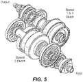
- the first clutch shaft output gear 111 and the second clutch shaft output gear 113 can both be meshed to the single output shaft gear 121, e.g., as shown in Figs. 1 and 5 .
- Any other suitable number of output shaft gears 121 is contemplated herein (e.g., one for each clutch shaft output gear).
- the transmission 100 can include a fourth speed through at least one of the first clutch shaft 105 or the second clutch shaft 107 as shown, for example.
- the one or more input shaft gears 103a, 103b, 103c, 103d include a fourth input shaft gear 103d fixed to the input shaft 101 to rotate with the input shaft 101.
- the one or more clutch shaft input gears 109a, 109b, 109c, 109d can include a fourth clutch shaft gear 109d meshed with the fourth input shaft gear 103d and mounted to the first clutch shaft 105 or the second clutch shaft 107 (e.g., as shown) via an overrunning clutch 131.
- the first speed can be achieved by moving the first synchronizer 125 in a first direction to engage the first input shaft gear 103a to the input shaft 101, which turns the first input shaft gear 103a with the input shaft 101 such that the first input shaft gear 103a drives the first clutch shaft input gear 109a, and by engaging the first clutch 115 to engage the first clutch shaft input gear 109a to the first clutch shaft 105 to turn the first clutch shaft 105 with the first clutch shaft input gear 109a, which turns the first clutch shaft output gear 111, which drives the output shaft gear 121 to turn the output shaft 119 in accordance with a first speed ratio relative to the input shaft 101.
- the second speed can be achieved by actuating the second synchronizer 127 to engage the second input shaft gear 103b to the input shaft 101, which turns the second input shaft gear 103b with the input shaft 101 such that the second input shaft gear 103b drives the second clutch shaft input gear 109b, and by engaging the second clutch 113 to engage the second clutch shaft input gear 109b to the second clutch shaft 107 to turn the second clutch shaft 107 with the second clutch shaft input gear 109b, which turns the second clutch shaft output gear 113, which drives the output shaft gear 121 to turn the output shaft 119 in accordance with a second speed ratio relative to the input shaft 101.
- the third speed can be achieved by moving the first synchronizer 125 in a second direction (e.g., to the right as shown, opposite the first direction) to engage the third input shaft gear 103c to the input shaft 101, which turns the third input shaft gear 103c with the input shaft 101 such that the third input shaft gear 103c drives the third clutch shaft input gear 109c, and by engaging the first clutch 105 to engage the third clutch shaft input gear 109c to the first clutch shaft 105 to turn the first clutch shaft 105 with the third clutch shaft input gear 109c, which turns the first clutch shaft output gear 111, which drives the output shaft gear 121 to turn the output shaft 119 in accordance with a third speed ratio relative to the input shaft 101.
- a second direction e.g., to the right as shown, opposite the first direction
- the fourth speed can be achieved by disengaging all clutches 115, 117 such that fourth input shaft gear 103d drives the fourth clutch shaft input gear 109d and the overrunning clutch 131 engages the fourth clutch shaft input gear 109d to the second clutch shaft 107, which turns the second clutch shaft output gear 113, which drives the output shaft gear 121 to turn the output shaft 119 in accordance with a fourth speed ratio relative to the input shaft 101.
- Any other suitable synchronizer and/or clutch arrangements and/or actuation schemes are contemplated herein.
- the first gear output speed can be faster than the second gear output speed
- the second gear output speed can be faster than the third gear output speed
- the third gear output speed can be faster than the fourth gear output speed. Any other suitable speeds and any suitable gear ratios are contemplated herein.
- a method for controlling a transmission can include actuating a first synchronizer in a first direction on an input shaft to engage a first input shaft gear to the input shaft to drive a first clutch shaft gear on a first clutch shaft, and engaging a first clutch to engage the first clutch shaft gear to the first clutch shaft to achieve a first speed, actuating a second synchronizer on the input shaft to engage a second input shaft gear to the input shaft to drive a second clutch shaft gear on a second clutch shaft, disengaging the first clutch while engaging a second clutch to engage the second clutch shaft gear to the second clutch shaft to achieve a second speed, and actuating the first synchronizer in a second direction on the input shaft to engage a third input shaft gear to the input shaft to drive the third clutch shaft gear on the first clutch shaft, disengaging the second clutch while engaging the first clutch to engage the third clutch shaft gear to the first clutch shaft to achieve a third speed.
- the transmission 100 can include one or more speed sensors disposed on the input shaft 101 and/or the output shaft 119, for example. Any other suitable sensors are contemplated herein. Any suitable controller (not shown) having any suitable hardware and/or software configured to receive sensor signals (e.g., from the one or more speed sensors) and to control shifting between speeds (e.g., by operating clutches 105, 107 and synchronizers 125, 127, e.g., as disclosed above) is contemplated herein. Any suitable additional components or logic as appreciated by those having ordinary skill in the art in view of this invention is contemplated herein. Certain embodiments can utilize a single speed sensor on the input shaft, but a second one on the output shaft can verify the correct gear is engaged. Certain embodiments can control based on input speed, and an output sensor can be used for protection.
- the method can include disengaging all synchronizers and clutches to cause an overrunning clutch to engage and to achieve a fourth speed.
- the method can include sensing speed at one or both of the input shaft and the output shaft using one or more speed sensors to determine when to actuate into a desired speed.
- the method can include providing hysteresis in shifting between speeds (e.g., having a lower upshift speed than a downshift speed between the same two gears), e.g., as shown. Any other suitable control method to achieve any suitable speed is contemplated herein.
- an aircraft turbomachine low speed spool transmission can include four speeds. Any other suitable number of speeds (e.g., 3, 5, 10, etc.) is contemplated herein.
- Embodiments as disclosed herein can be configured to operate with a turbomachine (e.g., an aircraft turbomachine).
- Embodiments include synchronizers on the input shaft, ahead of clutches, which is the opposite of a conventional transmission.
- Embodiments utilize one or more hydraulic clutches that have friction plates/discs attached to an inner wall of outer clutch bell, and other plates attached to an outer wall of inner clutch bell such that when a piston compresses against friction plates, the outer and inner bell are engaged.
- Embodiments include a dual clutch shifting transmission for use in a low spool turbomachine engine accessory drive.
- Embodiments can take a large rotational input speed range and convert it into one or more (e.g., several) tighter speed ranges.
- Embodiments of a dual clutch approach can result in less drop off in torque carrying capability during the shifts.
- Embodiments include a 4-speed dual clutch transmission for an aircraft low spool engine that can have dual clutches, 4 speeds, synchro-meshes, and an optional overrunning clutch.
- a desire by aircraft engine makers to extract power from the low spool engine for engine accessories (e.g., generators, pumps) instead of the high spool is hindered by the difference in speed ratios between the low spool and the accessories.
- Optimum accessory speed range ratios can be approximately 2:1 while the low spool speed range ratio could be as high as 10:1, for example. Taking power from the low spool allows the high spool to be made more efficient while also allowing for a lower idle speed which decreases brake wear.
- Embodiments can convert a wide low spool engine speed range ratio (e.g., about 8.1:1) into a narrow speed range ratio (e.g., about 2.2:1) for driving engine accessories.
- Speed sensors on the input and output of the transmission can work with a transmission controller to initiate shifting via clutches and synchronizers. Overlaps between the gear ratios can be provided to prevent doorbelling at the shift points (i.e., to provide hysteresis).
- any numerical values disclosed herein can be exact values or can be values within a range. Further, any terms of approximation (e.g., “about”, “approximately”, “around”) used in this invention can mean the stated value within a range. For example, in certain embodiments, the range can be within (plus or minus) 20%, or within 10%, or within 5%, or within 2%, or within any other suitable percentage or number as appreciated by those having ordinary skill in the art (e.g., for known tolerance limits or error ranges).
Landscapes
- Engineering & Computer Science (AREA)
- General Engineering & Computer Science (AREA)
- Mechanical Engineering (AREA)
- Chemical & Material Sciences (AREA)
- Combustion & Propulsion (AREA)
- Structure Of Transmissions (AREA)
Description
- This invention relates to transmissions, more specifically to multispeed transmission systems, e.g., for low speed spool turbomachine engines.
- Moving turbomachine engine accessories to the low speed spool requires a speed converting transmission to take a wide speed range and convert it into a narrow speed range. One method of doing this is the use of a shifting transmission consisting of clutches that selectively engage different gear ratios.
- Such conventional methods and systems have generally been considered satisfactory for their intended purpose. However, there is still a need in the art for improved transmission systems. The present invention provides a solution for this need. A transmission is described in
CN 2924171 . - A multispeed turbomachine transmission according to the invention is defined by
claim 1 Preferred embodiments are shown in the dependent claims. - A method for controlling such a transmission is defined by claim 11.
- Further according to the invention, an aircraft turbomachine low speed spool transmission is defined by claim 12.
- These and other features of the embodiments of the invention will become more readily apparent to those skilled in the art from the following detailed description taken in conjunction with the drawings.
- So that those skilled in the art to which the subject invention appertains will readily understand how to make and use the devices and methods of the invention without undue experimentation, embodiments thereof will be described in detail herein below with reference to certain figures, wherein:
-
Fig. 1 is a perspective view of an embodiments of a transmission in accordance with this invention; -
Fig. 2 is a cross-sectional view of the embodiment ofFig. 1 , sectioned through the input shaft and the output shaft; -
Fig. 3 is a cross-sectional view of an embodiment of a first clutch shaft of the embodiment ofFig. 1 ; -
Fig. 4 is a cross-sectional view of an embodiment of a second clutch shaft of the embodiment ofFig. 1 ; -
Fig. 5 is a perspective view of the embodiment ofFig. 1 ; -
Fig. 6 is a plan view of the embodiment ofFig. 1 ; -
Fig. 7 is a cross-sectional view of the embodiment ofFig. 1 , sectioned through the input shaft and the first clutch shaft; -
Fig. 8 is a cross-sectional view of the embodiment ofFig. 1 , sectioned through the input shaft and the second clutch shaft; -
Fig. 9 is a cross-sectional view of the embodiment ofFig. 1 , sectioned through the first clutch shaft and the output shaft; -
Fig. 10 is a schematic diagram of the embodiment ofFig. 1 , shown including speed sensors; -
Fig. 11 is a chart showing an embodiment of speed ratio curves of each transmission speed as well as speed ranges for an embodiment of accessories attached to the transmission; and -
Fig. 12 is a chart showing an embodiment of a control scheme having hysteresis overlaid on the speed lines ofFig. 11 . - Reference will now be made to the drawings wherein like reference numerals identify similar structural features or aspects of the subject invention.
- For purposes of explanation and illustration, and not limitation, an illustrative view of an embodiment of a transmission in accordance with the invention is shown in
Fig. 1 and is designated generally byreference character 100. Other embodiments and/or aspects of this invention are shown inFigs. 2-12 . - Referring generally to
Figs. 1-9 , amultispeed turbomachine transmission 100 can include aninput shaft 101 and a plurality ofinput shaft gears input shaft 101. Thetransmission 100 can include one ormore clutch shafts transmission 100 can include one or more clutchshaft input gears more clutch shafts input shaft gears transmission 100 can include at least one clutchshaft output gear clutch shaft - The
transmission 100 can include aclutch clutch shaft more clutches clutch shaft input gears shaft output gear 111, 113 (e.g., by engaging the one or more clutchshaft input gears respective clutch shaft - The
transmission 100 can include anoutput shaft 119 and at least oneoutput shaft gear 121 connected to theoutput shaft 119 and meshed with the at least one clutchshaft output gear - As shown in
Fig. 2 , for example, one or more of the plurality ofinput shaft gears input shaft 101 to be able to rotate relative to theinput shaft 101. One ormore synchronizers input shaft 101 and can be configured to selectively connect one or more of the plurality ofinput shaft gears input shaft 101 such that theinput shaft gears input shaft 101. - In certain embodiments, the one or
more synchronizers synchronizers sliding collar 129a (e.g., splined to amember 129b that is attached to and rotates with the input shaft 101), one ormore synchro rings 129c configured to be engaged by slidingcollar 129a, and one ormore friction cones 129d, each attached to a respectiveinput shaft gear synchro ring 129c to cause theinput shaft gear input shaft 101. When synchronized, thefriction cone 129d can then be engaged by the slidingcollar 129a to mechanically connect theinput shaft gear input shaft 101. Any other suitable synchronizer assembly and/or additionally actuation components are contemplated herein. - The one or
more clutch shafts first clutch shaft 105 having afirst clutch 115 disposed thereon. The one ormore clutch shafts second clutch shaft 107 having a second clutch disposed thereon 117. Any suitable number clutch shafts and clutches is contemplated herein. For example, all speeds can be located on a single shaft. - Referring additionally to
Figs. 3-6 , in certain embodiments, thetransmission 100 can include at least three speeds. As described herein, the term "speed" means a ratio of the input shaft to the output shaft as appreciated by those having ordinary skill in the art. A first speed can be through thefirst clutch shaft 105, a second speed can be through thesecond clutch shaft 107, and a third speed can be through thefirst clutch shaft 105. Any other suitable speed arrangement is contemplated herein. - The one or more
input shaft gears input shaft gear 103a, a secondinput shaft gear 103b, and a thirdinput shaft gear 103c, each configured to rotate relative to theinput shaft 101 when disengaged by the one ormore synchronizers input shaft 101 when engaged by the one ormore synchronizers shaft input gears shaft input gear 109a on thefirst clutch shaft 105 meshed with the firstinput shaft gear 103a and configured to rotate relative to thefirst clutch shaft 105 when thefirst clutch 115 is disengaged and to rotate with thefirst clutch shaft 105 when thefirst clutch 115 is engaged (e.g., when the clutch piston compresses one or more friction discs against one or more separator discs). - The one or more clutch
shaft input gears shaft input gear 109b on thesecond clutch shaft 107 meshed with the secondinput shaft gear 103b and configured to rotate relative to thesecond clutch shaft 107 when thesecond clutch 117 is disengaged and to rotate with thesecond clutch shaft 107 when thesecond clutch 117 is engaged. The one or more clutchshaft input gears shaft input gear 109c on thefirst clutch shaft 105 meshed with the thirdinput shaft gear 103c and configured to rotate relative to thefirst clutch shaft 105 when thefirst clutch 115 is disengaged and to rotate with thefirst clutch shaft 105 when thefirst clutch 115 is engaged. - In certain embodiments, as shown each of the first clutch
shaft input gear 109a, second clutchshaft input gear 109b, and third clutchshaft input gear 109c can be mounted to therespective clutch shaft input shaft gears shaft input gears more clutches - Referring additionally to
Figs. 7 and8 , the one ormore synchronizers first synchronizer 125 and asecond synchronizer 127. Thefirst synchronizer 125 can be configured to engage the firstinput shaft gear 103a to theinput shaft 101 when actuated in a first direction (e.g., to the left as shown inFig. 7 ), and to engage the thirdinput shaft gear 103c when actuated in a second direction (e.g., to the right as shown inFig. 7 ). Thesecond synchronizer 127 can be configured to engage the secondinput shaft gear 103b to theinput shaft 101 when actuated. Any other suitable arrangement is contemplated herein. - The at least one clutch
shaft output gear shaft output gear 111 fixed to the firstclutch shaft 105 to rotate with the firstclutch shaft 105 and a second clutchshaft output gear 113 fixed to the secondclutch shaft 107 to rotate with the secondclutch shaft 107. - Referring additionally to
Fig. 9 , the at least oneoutput shaft gear 121 can include a singleoutput shaft gear 121. The first clutchshaft output gear 111 and the second clutchshaft output gear 113 can both be meshed to the singleoutput shaft gear 121, e.g., as shown inFigs. 1 and5 . Any other suitable number of output shaft gears 121 is contemplated herein (e.g., one for each clutch shaft output gear). - The
transmission 100 can include a fourth speed through at least one of the firstclutch shaft 105 or the secondclutch shaft 107 as shown, for example. For example, the one or more input shaft gears 103a, 103b, 103c, 103d include a fourthinput shaft gear 103d fixed to theinput shaft 101 to rotate with theinput shaft 101. The one or more clutch shaft input gears 109a, 109b, 109c, 109d can include a fourthclutch shaft gear 109d meshed with the fourthinput shaft gear 103d and mounted to the firstclutch shaft 105 or the second clutch shaft 107 (e.g., as shown) via an overrunningclutch 131. - As indicated by the
numbers Figs. 7 ,8 , and10 , in certain embodiments, the first speed can be achieved by moving thefirst synchronizer 125 in a first direction to engage the firstinput shaft gear 103a to theinput shaft 101, which turns the firstinput shaft gear 103a with theinput shaft 101 such that the firstinput shaft gear 103a drives the first clutchshaft input gear 109a, and by engaging the first clutch 115 to engage the first clutchshaft input gear 109a to the firstclutch shaft 105 to turn the firstclutch shaft 105 with the first clutchshaft input gear 109a, which turns the first clutchshaft output gear 111, which drives theoutput shaft gear 121 to turn theoutput shaft 119 in accordance with a first speed ratio relative to theinput shaft 101. The second speed can be achieved by actuating thesecond synchronizer 127 to engage the secondinput shaft gear 103b to theinput shaft 101, which turns the secondinput shaft gear 103b with theinput shaft 101 such that the secondinput shaft gear 103b drives the second clutchshaft input gear 109b, and by engaging thesecond clutch 113 to engage the second clutchshaft input gear 109b to the secondclutch shaft 107 to turn the secondclutch shaft 107 with the second clutchshaft input gear 109b, which turns the second clutchshaft output gear 113, which drives theoutput shaft gear 121 to turn theoutput shaft 119 in accordance with a second speed ratio relative to theinput shaft 101. - The third speed can be achieved by moving the
first synchronizer 125 in a second direction (e.g., to the right as shown, opposite the first direction) to engage the thirdinput shaft gear 103c to theinput shaft 101, which turns the thirdinput shaft gear 103c with theinput shaft 101 such that the thirdinput shaft gear 103c drives the third clutchshaft input gear 109c, and by engaging the first clutch 105 to engage the third clutchshaft input gear 109c to the firstclutch shaft 105 to turn the firstclutch shaft 105 with the third clutchshaft input gear 109c, which turns the first clutchshaft output gear 111, which drives theoutput shaft gear 121 to turn theoutput shaft 119 in accordance with a third speed ratio relative to theinput shaft 101. In certain embodiments, the fourth speed can be achieved by disengaging allclutches input shaft gear 103d drives the fourth clutchshaft input gear 109d and the overrunningclutch 131 engages the fourth clutchshaft input gear 109d to the secondclutch shaft 107, which turns the second clutchshaft output gear 113, which drives theoutput shaft gear 121 to turn theoutput shaft 119 in accordance with a fourth speed ratio relative to theinput shaft 101. Any other suitable synchronizer and/or clutch arrangements and/or actuation schemes are contemplated herein. - Referring additionally to
Figs. 11 and12 , in certain embodiments, for a given input speed, the first gear output speed can be faster than the second gear output speed, the second gear output speed can be faster than the third gear output speed, and the third gear output speed can be faster than the fourth gear output speed. Any other suitable speeds and any suitable gear ratios are contemplated herein. - In accordance with at least one aspect of this invention, a method for controlling a transmission can include actuating a first synchronizer in a first direction on an input shaft to engage a first input shaft gear to the input shaft to drive a first clutch shaft gear on a first clutch shaft, and engaging a first clutch to engage the first clutch shaft gear to the first clutch shaft to achieve a first speed, actuating a second synchronizer on the input shaft to engage a second input shaft gear to the input shaft to drive a second clutch shaft gear on a second clutch shaft, disengaging the first clutch while engaging a second clutch to engage the second clutch shaft gear to the second clutch shaft to achieve a second speed, and actuating the first synchronizer in a second direction on the input shaft to engage a third input shaft gear to the input shaft to drive the third clutch shaft gear on the first clutch shaft, disengaging the second clutch while engaging the first clutch to engage the third clutch shaft gear to the first clutch shaft to achieve a third speed.
- As shown in
Fig. 10 , thetransmission 100 can include one or more speed sensors disposed on theinput shaft 101 and/or theoutput shaft 119, for example. Any other suitable sensors are contemplated herein. Any suitable controller (not shown) having any suitable hardware and/or software configured to receive sensor signals (e.g., from the one or more speed sensors) and to control shifting between speeds (e.g., by operatingclutches synchronizers - The method can include disengaging all synchronizers and clutches to cause an overrunning clutch to engage and to achieve a fourth speed. The method can include sensing speed at one or both of the input shaft and the output shaft using one or more speed sensors to determine when to actuate into a desired speed. The method can include providing hysteresis in shifting between speeds (e.g., having a lower upshift speed than a downshift speed between the same two gears), e.g., as shown. Any other suitable control method to achieve any suitable speed is contemplated herein.
- In accordance with at least one aspect, an aircraft turbomachine low speed spool transmission can include four speeds. Any other suitable number of speeds (e.g., 3, 5, 10, etc.) is contemplated herein.
- Embodiments as disclosed herein (e.g., described above) can be configured to operate with a turbomachine (e.g., an aircraft turbomachine). Embodiments include synchronizers on the input shaft, ahead of clutches, which is the opposite of a conventional transmission. Embodiments utilize one or more hydraulic clutches that have friction plates/discs attached to an inner wall of outer clutch bell, and other plates attached to an outer wall of inner clutch bell such that when a piston compresses against friction plates, the outer and inner bell are engaged.
- Embodiments include a dual clutch shifting transmission for use in a low spool turbomachine engine accessory drive. Embodiments can take a large rotational input speed range and convert it into one or more (e.g., several) tighter speed ranges. Embodiments of a dual clutch approach can result in less drop off in torque carrying capability during the shifts.
- Embodiments include a 4-speed dual clutch transmission for an aircraft low spool engine that can have dual clutches, 4 speeds, synchro-meshes, and an optional overrunning clutch. A desire by aircraft engine makers to extract power from the low spool engine for engine accessories (e.g., generators, pumps) instead of the high spool is hindered by the difference in speed ratios between the low spool and the accessories. Optimum accessory speed range ratios can be approximately 2:1 while the low spool speed range ratio could be as high as 10:1, for example. Taking power from the low spool allows the high spool to be made more efficient while also allowing for a lower idle speed which decreases brake wear.
- Embodiments can convert a wide low spool engine speed range ratio (e.g., about 8.1:1) into a narrow speed range ratio (e.g., about 2.2:1) for driving engine accessories. Speed sensors on the input and output of the transmission can work with a transmission controller to initiate shifting via clutches and synchronizers. Overlaps between the gear ratios can be provided to prevent doorbelling at the shift points (i.e., to provide hysteresis).
- Those having ordinary skill in the art understand that any numerical values disclosed herein can be exact values or can be values within a range. Further, any terms of approximation (e.g., "about", "approximately", "around") used in this invention can mean the stated value within a range. For example, in certain embodiments, the range can be within (plus or minus) 20%, or within 10%, or within 5%, or within 2%, or within any other suitable percentage or number as appreciated by those having ordinary skill in the art (e.g., for known tolerance limits or error ranges).
- Any suitable combination(s) of any disclosed embodiments and/or any suitable portion(s) thereof are contemplated herein as appreciated by those having ordinary skill in the art.
- The embodiments of the present invention, as described above and shown in the drawings, provide for improvement in the art to which they pertain. While the subject invention includes reference to certain embodiments, those skilled in the art will readily appreciate that changes and/or modifications may be made thereto without departing from the scope of the invention as defined by the claims.
Claims (12)
- A multispeed turbomachine transmission, comprising:an input shaft (101);a plurality of input shaft gears (103) disposed on the input shaft;a first clutch shaft (105) having a first clutch (115) disposed thereon, and a second clutch shaft (107) having a second clutch (117) disposed thereon;clutch shaft input gears (109) disposed on the first and second clutch shafts, each meshed with one of the plurality of input shaft gears;a first clutch shaft output gear (111) fixed to the first clutch shaft to rotate with the first clutch shaft and a second clutch shaft output gear (113) fixed to the second clutch shaft to rotate with the second clutch shaft;the first and second clutches (115, 117) respectively connected to the first and second clutch shaft and configured to selectively connect the clutch shaft input gears to the first and second clutch shaft output gears (111, 113);an output shaft (119); andat least one output shaft gear (121) connected to the output shaft and meshed with the first and second clutch shaft output gears (111, 113);wherein one or more of the plurality of input shaft gears (103) are rotatably mounted to the input shaft (101) to be able to rotate relative to the input shaft (101); andwherein the transmission includes three speeds, wherein a first speed is through the first clutch shaft (105), a second speed is through the second clutch shaft (107), and a third speed is through the first clutch shaft (105); and characterized by further comprising a first synchronizer (125) and a second synchronizer (127) disposed on the input shaft and configured to selectively connect one or more of the plurality of input shaft gears (103) to the input shaft (101) such that the input shaft gears rotate with the input shaft;wherein the plurality of input shaft gears include a first input shaft gear (103a), a second input shaft gear (103b), and a third input shaft gear (103c) each configured to rotate relative to the input shaft when disengaged by the first and second synchronizers (125, 127) and to rotate with the shaft when engaged by the synchronizers; andwherein the clutch shaft input gears (109) include a first clutch shaft input gear (109a) on the first clutch shaft meshed with the first input shaft gear and configured to rotate relative to the first clutch shaft when the first clutch is disengaged and to rotate with the first clutch shaft when the first clutch is engaged, wherein the one or more clutch shaft input gears include a second clutch shaft input gear (109b) on the second clutch shaft meshed with the second input shaft gear and configured to rotate relative to the second clutch shaft when the second clutch is disengaged and to rotate with the second clutch shaft when the second clutch is engaged, and wherein the one or more clutch shaft input gears include a third clutch shaft input gear (109c) on the first clutch shaft meshed with the third input shaft gear and configured to rotate relative to the first clutch shaft when the first clutch is disengaged and to rotate with the first clutch shaft when the first clutch is engaged, wherein the first synchronizer (125) is configured to engage the first input shaft gear to the input shaft when actuated in a first direction, and to engage the third input shaft gear when actuated in a second direction, wherein the second synchronizer (127) is configured to engage the second input shaft gear to the input shaft when actuated.
- The transmission of claim 1, wherein the one synchronizers (125, 127) include at least one synchromesh.
- The transmission of claim 1 or 2, wherein the at least one output shaft gear (121) includes a single output shaft gear, wherein the first clutch shaft output gear and the second clutch shaft output gear are both meshed to the single output shaft gear.
- The transmission of claim 1, 2 or 3, wherein the transmission includes a fourth speed through at least one of the first clutch shaft or the second clutch shaft.
- The transmission of claim 4, wherein the one or more input shaft gears include a fourth input shaft gear (103d) fixed to the input shaft to rotate with the input shaft, and wherein the one or more clutch shaft input gears include a fourth clutch shaft gear (109d) mounted to the first clutch shaft or the second clutch shaft via an overrunning clutch.
- The transmission of claim 5, wherein the first speed is achieved by moving the first synchronizer (125) in a first direction to engage the first input shaft gear (103a) to the input shaft (101), which turns the first input shaft gear with the input shaft such that the first input shaft gear drives the first clutch shaft input gear, and engaging the first clutch (115) to engage the first clutch shaft input gear (109a) to the first clutch shaft (105) to turn the first clutch shaft with the first clutch shaft input gear, which turns the first clutch shaft output gear, which drives the output shaft gear to turn the output shaft in accordance with a first speed ratio relative to the input shaft.
- The transmission of claim 6, wherein the second speed is achieved by actuating the second synchronizer (127) to engage the second input shaft gear (103b) to the input shaft (101), which turns the second input shaft gear with the input shaft such that the second input shaft gear drives the second clutch shaft input gear (109b), and engaging the second clutch to engage the second clutch shaft input gear to the second clutch shaft to turn the second clutch shaft with the second clutch shaft input gear, which turns the second clutch shaft output gear, which drives the output shaft gear (113, 115) to turn the output shaft in accordance with a second speed ratio relative to the input shaft.
- The transmission of claim 7, wherein the third speed is achieved by moving the first synchronizer (125) in a second direction to engage the third input shaft gear (103c) to the input shaft, which turns the third input shaft gear with the input shaft such that the third input shaft gear drives the third clutch shaft input gear (109c), and engaging the first clutch to engage the third clutch shaft input gear to the first clutch shaft to turn the first clutch shaft with the third clutch shaft input gear, which turns the first clutch shaft output gear, which drives the output shaft gear to turn the output shaft in accordance with a third speed ratio relative to the input shaft.
- The transmission of claim 8, wherein the fourth speed is achieved by disengaging all synchronizers and all clutches such that fourth input shaft gear (103d) drives the fourth clutch shaft input gear (109d) and the overrunning clutch engages the fourth clutch shaft input gear to the second clutch shaft, which turns the second clutch shaft output gear, which drives the output shaft gear to turn the output shaft in accordance with a fourth speed ratio relative to the input shaft.
- The transmission of any preceding claim, wherein for a given input speed, the first gear output speed is faster than the second gear output speed, wherein the second gear output speed is faster than the third gear output speed, wherein the third gear output speed is faster than the fourth gear output speed.
- A method for controlling a transmission as claimed in any preceding claim, comprising:actuating the first synchronizer (125) in a first direction on the input shaft (101) to engage the first input shaft gear (103a) to the input shaft to drive the first clutch shaft gear on the first clutch shaft, and engaging the first clutch (115) to engage the first clutch shaft gear to the first clutch shaft to achieve the first speed;actuating the second synchronizer (127) on the input shaft to engage the second input shaft gear to the input shaft to drive the second clutch shaft gear (103b) on the second clutch shaft, disengaging the first clutch while engaging the second clutch to engage the second clutch shaft gear (103b) to the second clutch shaft to achieve the second speed; andactuating the first synchronizer in a second direction on the input shaft to engage the third input shaft gear (103c) to the input shaft to drive the third clutch shaft gear on the first clutch shaft, disengaging the second clutch while engaging the first clutch to engage the third clutch shaft gear to the first clutch shaft to achieve the third speed.
- An aircraft turbomachine low speed spool transmission being a transmission as claimed in any of claims 4 to 9, comprising four speeds.
Applications Claiming Priority (1)
| Application Number | Priority Date | Filing Date | Title |
|---|---|---|---|
| US16/387,961 US11226026B2 (en) | 2019-04-18 | 2019-04-18 | Multispeed transmission |
Publications (2)
| Publication Number | Publication Date |
|---|---|
| EP3726095A1 EP3726095A1 (en) | 2020-10-21 |
| EP3726095B1 true EP3726095B1 (en) | 2022-10-19 |
Family
ID=68610063
Family Applications (1)
| Application Number | Title | Priority Date | Filing Date |
|---|---|---|---|
| EP19209843.2A Active EP3726095B1 (en) | 2019-04-18 | 2019-11-18 | Multispeed transmission |
Country Status (2)
| Country | Link |
|---|---|
| US (1) | US11226026B2 (en) |
| EP (1) | EP3726095B1 (en) |
Families Citing this family (5)
| Publication number | Priority date | Publication date | Assignee | Title |
|---|---|---|---|---|
| US12084195B2 (en) | 2021-04-29 | 2024-09-10 | Hamilton Sundstrand Corporation | Dual drive, dual clutch drive system for an aircraft accessory |
| US20220349349A1 (en) * | 2021-04-29 | 2022-11-03 | Hamilton Sundstrand Corporation | Single drive, dual clutch drive system for an aircraft accessory |
| US11808211B2 (en) | 2022-04-08 | 2023-11-07 | Hamilton Sundstrand Corporation | Multi-speed transmission to control variable APU speed and constant generator output frequency |
| US11697998B1 (en) | 2022-04-08 | 2023-07-11 | Hamilton Sundstrand Corporation | Constant speed drive to control variable APU speed and constant generator output frequency |
| DE102023206307B4 (en) * | 2023-07-04 | 2025-09-11 | Zf Friedrichshafen Ag | Powershift transmission and method for shifting a powershift transmission |
Family Cites Families (17)
| Publication number | Priority date | Publication date | Assignee | Title |
|---|---|---|---|---|
| DE19840084A1 (en) | 1998-09-03 | 2000-03-09 | Zahnradfabrik Friedrichshafen | Marine gear |
| JP4082926B2 (en) | 2002-05-07 | 2008-04-30 | 本田技研工業株式会社 | Automatic transmission |
| GB0426165D0 (en) | 2004-11-29 | 2004-12-29 | Ricardo Uk Ltd | Twin layshaft manual transmission |
| US7597020B2 (en) * | 2005-03-17 | 2009-10-06 | Ford Global Technologies, Llc | Gear selection strategy for a dual clutch transmission |
| CN2924171Y (en) | 2006-05-31 | 2007-07-18 | 华南理工大学 | Dual-clutch type automatic transmission for preventing two-gear from being locked |
| US7942079B2 (en) | 2007-02-16 | 2011-05-17 | Hamilton Sundstrand Corporation | Multi-speed gearbox for low spool driven auxiliary component |
| DE102009006647B4 (en) | 2008-02-04 | 2019-01-31 | Schaeffler Technologies AG & Co. KG | Dual clutch assembly |
| US8647078B2 (en) | 2011-02-24 | 2014-02-11 | Ford Global Technologies, Llc | Motor pump assembly for transmission valve body |
| KR101408453B1 (en) * | 2012-10-12 | 2014-06-17 | 강명구 | Multiple Hydraulic Wet Clutch Transmission for vehicles |
| US9003906B2 (en) * | 2013-03-15 | 2015-04-14 | Gm Global Technology Operations, Llc | Eleven speed dual clutch transmission |
| US9347373B2 (en) | 2013-12-19 | 2016-05-24 | Pratt & Whitney Canada Corp. | Gas turbine engine with transmission |
| US10844935B2 (en) | 2014-07-18 | 2020-11-24 | Uvic Industry Partnerships Inc. | Electric drive system with a novel dual-clutch transmission |
| US10167948B2 (en) | 2016-03-17 | 2019-01-01 | GM Global Technology Operations LLC | Hydraulic control system for an automatic transmission |
| US10674178B2 (en) | 2016-07-15 | 2020-06-02 | Samsung Electronics Co., Ltd. | One-dimensional segmentation for coherent motion estimation |
| US20180045119A1 (en) | 2016-08-09 | 2018-02-15 | United Technologies Corporation | Geared turbofan with low spool power extraction |
| US10995673B2 (en) | 2017-01-19 | 2021-05-04 | Raytheon Technologies Corporation | Gas turbine engine with intercooled cooling air and dual towershaft accessory gearbox |
| US10495186B2 (en) | 2017-01-20 | 2019-12-03 | Hamilton Sundstrand Corporation | Low speed spool generator transmission |
-
2019
- 2019-04-18 US US16/387,961 patent/US11226026B2/en active Active
- 2019-11-18 EP EP19209843.2A patent/EP3726095B1/en active Active
Also Published As
| Publication number | Publication date |
|---|---|
| EP3726095A1 (en) | 2020-10-21 |
| US20200332862A1 (en) | 2020-10-22 |
| US11226026B2 (en) | 2022-01-18 |
Similar Documents
| Publication | Publication Date | Title |
|---|---|---|
| EP3726095B1 (en) | Multispeed transmission | |
| US8308609B2 (en) | Power-off downshift engagement dampening | |
| KR100189712B1 (en) | Driveline torque limit control strategy using sae j1922 type engine control | |
| KR100300297B1 (en) | Power Synchronizer for Combined Transmission | |
| JP5812356B2 (en) | Automotive multi-clutch transmission | |
| JP2006029476A (en) | Driving force transmission device | |
| US7779714B2 (en) | Surrogate engine speed signal for controlling a dual clutch powershift transmission | |
| JPS61233264A (en) | Clutch structure for separating and bypassing torque converter for automatic machine gearing | |
| JP4502103B2 (en) | Automatic transmission | |
| KR20140005457A (en) | Automated manual transmission for vehicle | |
| JP2010216605A (en) | Transmission | |
| KR102785690B1 (en) | Hybrid powertrain | |
| US8696518B2 (en) | Hydraulic control for powershift transmission | |
| WO2017209229A1 (en) | Control device for dual clutch transmission | |
| US6779417B2 (en) | Power transmission system | |
| KR20210109064A (en) | Hybrid powertrain for vehicle | |
| US5390562A (en) | Power transmission and control | |
| US10975935B2 (en) | Dual clutch-type transmission | |
| KR20210108518A (en) | Hybrid powertrain for vehicle | |
| JP2005042798A (en) | Shift control device for synchromesh type automatic transmission | |
| JP2004196055A (en) | Automatic transmission | |
| JP3712660B2 (en) | Power transmission device | |
| JP2005090604A (en) | Shift control device for automatic transmission | |
| JP2018013213A (en) | Transmission control device | |
| JP2005299708A (en) | Parallel shaft transmission |
Legal Events
| Date | Code | Title | Description |
|---|---|---|---|
| PUAI | Public reference made under article 153(3) epc to a published international application that has entered the european phase |
Free format text: ORIGINAL CODE: 0009012 |
|
| STAA | Information on the status of an ep patent application or granted ep patent |
Free format text: STATUS: THE APPLICATION HAS BEEN PUBLISHED |
|
| AK | Designated contracting states |
Kind code of ref document: A1 Designated state(s): AL AT BE BG CH CY CZ DE DK EE ES FI FR GB GR HR HU IE IS IT LI LT LU LV MC MK MT NL NO PL PT RO RS SE SI SK SM TR |
|
| AX | Request for extension of the european patent |
Extension state: BA ME |
|
| STAA | Information on the status of an ep patent application or granted ep patent |
Free format text: STATUS: REQUEST FOR EXAMINATION WAS MADE |
|
| 17P | Request for examination filed |
Effective date: 20210421 |
|
| RBV | Designated contracting states (corrected) |
Designated state(s): AL AT BE BG CH CY CZ DE DK EE ES FI FR GB GR HR HU IE IS IT LI LT LU LV MC MK MT NL NO PL PT RO RS SE SI SK SM TR |
|
| STAA | Information on the status of an ep patent application or granted ep patent |
Free format text: STATUS: EXAMINATION IS IN PROGRESS |
|
| 17Q | First examination report despatched |
Effective date: 20210531 |
|
| GRAP | Despatch of communication of intention to grant a patent |
Free format text: ORIGINAL CODE: EPIDOSNIGR1 |
|
| STAA | Information on the status of an ep patent application or granted ep patent |
Free format text: STATUS: GRANT OF PATENT IS INTENDED |
|
| INTG | Intention to grant announced |
Effective date: 20220321 |
|
| GRAS | Grant fee paid |
Free format text: ORIGINAL CODE: EPIDOSNIGR3 |
|
| GRAA | (expected) grant |
Free format text: ORIGINAL CODE: 0009210 |
|
| STAA | Information on the status of an ep patent application or granted ep patent |
Free format text: STATUS: THE PATENT HAS BEEN GRANTED |
|
| AK | Designated contracting states |
Kind code of ref document: B1 Designated state(s): AL AT BE BG CH CY CZ DE DK EE ES FI FR GB GR HR HU IE IS IT LI LT LU LV MC MK MT NL NO PL PT RO RS SE SI SK SM TR |
|
| REG | Reference to a national code |
Ref country code: GB Ref legal event code: FG4D |
|
| REG | Reference to a national code |
Ref country code: CH Ref legal event code: EP |
|
| REG | Reference to a national code |
Ref country code: IE Ref legal event code: FG4D |
|
| REG | Reference to a national code |
Ref country code: DE Ref legal event code: R096 Ref document number: 602019020764 Country of ref document: DE |
|
| REG | Reference to a national code |
Ref country code: AT Ref legal event code: REF Ref document number: 1525723 Country of ref document: AT Kind code of ref document: T Effective date: 20221115 |
|
| REG | Reference to a national code |
Ref country code: LT Ref legal event code: MG9D |
|
| REG | Reference to a national code |
Ref country code: NL Ref legal event code: MP Effective date: 20221019 |
|
| REG | Reference to a national code |
Ref country code: AT Ref legal event code: MK05 Ref document number: 1525723 Country of ref document: AT Kind code of ref document: T Effective date: 20221019 |
|
| PG25 | Lapsed in a contracting state [announced via postgrant information from national office to epo] |
Ref country code: NL Free format text: LAPSE BECAUSE OF FAILURE TO SUBMIT A TRANSLATION OF THE DESCRIPTION OR TO PAY THE FEE WITHIN THE PRESCRIBED TIME-LIMIT Effective date: 20221019 |
|
| PG25 | Lapsed in a contracting state [announced via postgrant information from national office to epo] |
Ref country code: SE Free format text: LAPSE BECAUSE OF FAILURE TO SUBMIT A TRANSLATION OF THE DESCRIPTION OR TO PAY THE FEE WITHIN THE PRESCRIBED TIME-LIMIT Effective date: 20221019 Ref country code: PT Free format text: LAPSE BECAUSE OF FAILURE TO SUBMIT A TRANSLATION OF THE DESCRIPTION OR TO PAY THE FEE WITHIN THE PRESCRIBED TIME-LIMIT Effective date: 20230220 Ref country code: NO Free format text: LAPSE BECAUSE OF FAILURE TO SUBMIT A TRANSLATION OF THE DESCRIPTION OR TO PAY THE FEE WITHIN THE PRESCRIBED TIME-LIMIT Effective date: 20230119 Ref country code: LT Free format text: LAPSE BECAUSE OF FAILURE TO SUBMIT A TRANSLATION OF THE DESCRIPTION OR TO PAY THE FEE WITHIN THE PRESCRIBED TIME-LIMIT Effective date: 20221019 Ref country code: FI Free format text: LAPSE BECAUSE OF FAILURE TO SUBMIT A TRANSLATION OF THE DESCRIPTION OR TO PAY THE FEE WITHIN THE PRESCRIBED TIME-LIMIT Effective date: 20221019 Ref country code: ES Free format text: LAPSE BECAUSE OF FAILURE TO SUBMIT A TRANSLATION OF THE DESCRIPTION OR TO PAY THE FEE WITHIN THE PRESCRIBED TIME-LIMIT Effective date: 20221019 Ref country code: AT Free format text: LAPSE BECAUSE OF FAILURE TO SUBMIT A TRANSLATION OF THE DESCRIPTION OR TO PAY THE FEE WITHIN THE PRESCRIBED TIME-LIMIT Effective date: 20221019 |
|
| PG25 | Lapsed in a contracting state [announced via postgrant information from national office to epo] |
Ref country code: RS Free format text: LAPSE BECAUSE OF FAILURE TO SUBMIT A TRANSLATION OF THE DESCRIPTION OR TO PAY THE FEE WITHIN THE PRESCRIBED TIME-LIMIT Effective date: 20221019 Ref country code: PL Free format text: LAPSE BECAUSE OF FAILURE TO SUBMIT A TRANSLATION OF THE DESCRIPTION OR TO PAY THE FEE WITHIN THE PRESCRIBED TIME-LIMIT Effective date: 20221019 Ref country code: LV Free format text: LAPSE BECAUSE OF FAILURE TO SUBMIT A TRANSLATION OF THE DESCRIPTION OR TO PAY THE FEE WITHIN THE PRESCRIBED TIME-LIMIT Effective date: 20221019 Ref country code: IS Free format text: LAPSE BECAUSE OF FAILURE TO SUBMIT A TRANSLATION OF THE DESCRIPTION OR TO PAY THE FEE WITHIN THE PRESCRIBED TIME-LIMIT Effective date: 20230219 Ref country code: HR Free format text: LAPSE BECAUSE OF FAILURE TO SUBMIT A TRANSLATION OF THE DESCRIPTION OR TO PAY THE FEE WITHIN THE PRESCRIBED TIME-LIMIT Effective date: 20221019 Ref country code: GR Free format text: LAPSE BECAUSE OF FAILURE TO SUBMIT A TRANSLATION OF THE DESCRIPTION OR TO PAY THE FEE WITHIN THE PRESCRIBED TIME-LIMIT Effective date: 20230120 |
|
| REG | Reference to a national code |
Ref country code: CH Ref legal event code: PL |
|
| P01 | Opt-out of the competence of the unified patent court (upc) registered |
Effective date: 20230604 |
|
| REG | Reference to a national code |
Ref country code: DE Ref legal event code: R097 Ref document number: 602019020764 Country of ref document: DE |
|
| REG | Reference to a national code |
Ref country code: BE Ref legal event code: MM Effective date: 20221130 |
|
| PG25 | Lapsed in a contracting state [announced via postgrant information from national office to epo] |
Ref country code: SM Free format text: LAPSE BECAUSE OF FAILURE TO SUBMIT A TRANSLATION OF THE DESCRIPTION OR TO PAY THE FEE WITHIN THE PRESCRIBED TIME-LIMIT Effective date: 20221019 Ref country code: RO Free format text: LAPSE BECAUSE OF FAILURE TO SUBMIT A TRANSLATION OF THE DESCRIPTION OR TO PAY THE FEE WITHIN THE PRESCRIBED TIME-LIMIT Effective date: 20221019 Ref country code: MC Free format text: LAPSE BECAUSE OF FAILURE TO SUBMIT A TRANSLATION OF THE DESCRIPTION OR TO PAY THE FEE WITHIN THE PRESCRIBED TIME-LIMIT Effective date: 20221019 Ref country code: LI Free format text: LAPSE BECAUSE OF NON-PAYMENT OF DUE FEES Effective date: 20221130 Ref country code: EE Free format text: LAPSE BECAUSE OF FAILURE TO SUBMIT A TRANSLATION OF THE DESCRIPTION OR TO PAY THE FEE WITHIN THE PRESCRIBED TIME-LIMIT Effective date: 20221019 Ref country code: DK Free format text: LAPSE BECAUSE OF FAILURE TO SUBMIT A TRANSLATION OF THE DESCRIPTION OR TO PAY THE FEE WITHIN THE PRESCRIBED TIME-LIMIT Effective date: 20221019 Ref country code: CZ Free format text: LAPSE BECAUSE OF FAILURE TO SUBMIT A TRANSLATION OF THE DESCRIPTION OR TO PAY THE FEE WITHIN THE PRESCRIBED TIME-LIMIT Effective date: 20221019 Ref country code: CH Free format text: LAPSE BECAUSE OF NON-PAYMENT OF DUE FEES Effective date: 20221130 |
|
| PLBE | No opposition filed within time limit |
Free format text: ORIGINAL CODE: 0009261 |
|
| STAA | Information on the status of an ep patent application or granted ep patent |
Free format text: STATUS: NO OPPOSITION FILED WITHIN TIME LIMIT |
|
| PG25 | Lapsed in a contracting state [announced via postgrant information from national office to epo] |
Ref country code: SK Free format text: LAPSE BECAUSE OF FAILURE TO SUBMIT A TRANSLATION OF THE DESCRIPTION OR TO PAY THE FEE WITHIN THE PRESCRIBED TIME-LIMIT Effective date: 20221019 Ref country code: LU Free format text: LAPSE BECAUSE OF NON-PAYMENT OF DUE FEES Effective date: 20221118 Ref country code: AL Free format text: LAPSE BECAUSE OF FAILURE TO SUBMIT A TRANSLATION OF THE DESCRIPTION OR TO PAY THE FEE WITHIN THE PRESCRIBED TIME-LIMIT Effective date: 20221019 |
|
| 26N | No opposition filed |
Effective date: 20230720 |
|
| PG25 | Lapsed in a contracting state [announced via postgrant information from national office to epo] |
Ref country code: IE Free format text: LAPSE BECAUSE OF NON-PAYMENT OF DUE FEES Effective date: 20221118 |
|
| PG25 | Lapsed in a contracting state [announced via postgrant information from national office to epo] |
Ref country code: SI Free format text: LAPSE BECAUSE OF FAILURE TO SUBMIT A TRANSLATION OF THE DESCRIPTION OR TO PAY THE FEE WITHIN THE PRESCRIBED TIME-LIMIT Effective date: 20221019 Ref country code: BE Free format text: LAPSE BECAUSE OF NON-PAYMENT OF DUE FEES Effective date: 20221130 |
|
| PG25 | Lapsed in a contracting state [announced via postgrant information from national office to epo] |
Ref country code: CY Free format text: LAPSE BECAUSE OF FAILURE TO SUBMIT A TRANSLATION OF THE DESCRIPTION OR TO PAY THE FEE WITHIN THE PRESCRIBED TIME-LIMIT Effective date: 20221019 |
|
| PG25 | Lapsed in a contracting state [announced via postgrant information from national office to epo] |
Ref country code: MK Free format text: LAPSE BECAUSE OF FAILURE TO SUBMIT A TRANSLATION OF THE DESCRIPTION OR TO PAY THE FEE WITHIN THE PRESCRIBED TIME-LIMIT Effective date: 20221019 Ref country code: IT Free format text: LAPSE BECAUSE OF FAILURE TO SUBMIT A TRANSLATION OF THE DESCRIPTION OR TO PAY THE FEE WITHIN THE PRESCRIBED TIME-LIMIT Effective date: 20221019 Ref country code: HU Free format text: LAPSE BECAUSE OF FAILURE TO SUBMIT A TRANSLATION OF THE DESCRIPTION OR TO PAY THE FEE WITHIN THE PRESCRIBED TIME-LIMIT; INVALID AB INITIO Effective date: 20191118 |
|
| PG25 | Lapsed in a contracting state [announced via postgrant information from national office to epo] |
Ref country code: TR Free format text: LAPSE BECAUSE OF FAILURE TO SUBMIT A TRANSLATION OF THE DESCRIPTION OR TO PAY THE FEE WITHIN THE PRESCRIBED TIME-LIMIT Effective date: 20221019 |
|
| PG25 | Lapsed in a contracting state [announced via postgrant information from national office to epo] |
Ref country code: BG Free format text: LAPSE BECAUSE OF FAILURE TO SUBMIT A TRANSLATION OF THE DESCRIPTION OR TO PAY THE FEE WITHIN THE PRESCRIBED TIME-LIMIT Effective date: 20221019 |
|
| PG25 | Lapsed in a contracting state [announced via postgrant information from national office to epo] |
Ref country code: MT Free format text: LAPSE BECAUSE OF FAILURE TO SUBMIT A TRANSLATION OF THE DESCRIPTION OR TO PAY THE FEE WITHIN THE PRESCRIBED TIME-LIMIT Effective date: 20221019 |
|
| PGFP | Annual fee paid to national office [announced via postgrant information from national office to epo] |
Ref country code: DE Payment date: 20251022 Year of fee payment: 7 |
|
| PGFP | Annual fee paid to national office [announced via postgrant information from national office to epo] |
Ref country code: GB Payment date: 20251023 Year of fee payment: 7 |
|
| PGFP | Annual fee paid to national office [announced via postgrant information from national office to epo] |
Ref country code: FR Payment date: 20251022 Year of fee payment: 7 |