EP3726091A1 - Damping stopper - Google Patents
Damping stopper Download PDFInfo
- Publication number
- EP3726091A1 EP3726091A1 EP18889488.5A EP18889488A EP3726091A1 EP 3726091 A1 EP3726091 A1 EP 3726091A1 EP 18889488 A EP18889488 A EP 18889488A EP 3726091 A1 EP3726091 A1 EP 3726091A1
- Authority
- EP
- European Patent Office
- Prior art keywords
- elastic body
- side wall
- damping stopper
- members
- radially outward
- Prior art date
- Legal status (The legal status is an assumption and is not a legal conclusion. Google has not performed a legal analysis and makes no representation as to the accuracy of the status listed.)
- Granted
Links
Images



Classifications
-
- F—MECHANICAL ENGINEERING; LIGHTING; HEATING; WEAPONS; BLASTING
- F16—ENGINEERING ELEMENTS AND UNITS; GENERAL MEASURES FOR PRODUCING AND MAINTAINING EFFECTIVE FUNCTIONING OF MACHINES OR INSTALLATIONS; THERMAL INSULATION IN GENERAL
- F16F—SPRINGS; SHOCK-ABSORBERS; MEANS FOR DAMPING VIBRATION
- F16F1/00—Springs
- F16F1/36—Springs made of rubber or other material having high internal friction, e.g. thermoplastic elastomers
- F16F1/3615—Springs made of rubber or other material having high internal friction, e.g. thermoplastic elastomers with means for modifying the spring characteristic
-
- F—MECHANICAL ENGINEERING; LIGHTING; HEATING; WEAPONS; BLASTING
- F16—ENGINEERING ELEMENTS AND UNITS; GENERAL MEASURES FOR PRODUCING AND MAINTAINING EFFECTIVE FUNCTIONING OF MACHINES OR INSTALLATIONS; THERMAL INSULATION IN GENERAL
- F16F—SPRINGS; SHOCK-ABSORBERS; MEANS FOR DAMPING VIBRATION
- F16F7/00—Vibration-dampers; Shock-absorbers
-
- F—MECHANICAL ENGINEERING; LIGHTING; HEATING; WEAPONS; BLASTING
- F16—ENGINEERING ELEMENTS AND UNITS; GENERAL MEASURES FOR PRODUCING AND MAINTAINING EFFECTIVE FUNCTIONING OF MACHINES OR INSTALLATIONS; THERMAL INSULATION IN GENERAL
- F16F—SPRINGS; SHOCK-ABSORBERS; MEANS FOR DAMPING VIBRATION
- F16F13/00—Units comprising springs of the non-fluid type as well as vibration-dampers, shock-absorbers, or fluid springs
- F16F13/02—Units comprising springs of the non-fluid type as well as vibration-dampers, shock-absorbers, or fluid springs damping by frictional contact between the spring and braking means
-
- B—PERFORMING OPERATIONS; TRANSPORTING
- B62—LAND VEHICLES FOR TRAVELLING OTHERWISE THAN ON RAILS
- B62D—MOTOR VEHICLES; TRAILERS
- B62D3/00—Steering gears
- B62D3/02—Steering gears mechanical
- B62D3/12—Steering gears mechanical of rack-and-pinion type
-
- B—PERFORMING OPERATIONS; TRANSPORTING
- B62—LAND VEHICLES FOR TRAVELLING OTHERWISE THAN ON RAILS
- B62D—MOTOR VEHICLES; TRAILERS
- B62D3/00—Steering gears
- B62D3/02—Steering gears mechanical
- B62D3/12—Steering gears mechanical of rack-and-pinion type
- B62D3/123—Steering gears mechanical of rack-and-pinion type characterised by pressure yokes
-
- B—PERFORMING OPERATIONS; TRANSPORTING
- B62—LAND VEHICLES FOR TRAVELLING OTHERWISE THAN ON RAILS
- B62D—MOTOR VEHICLES; TRAILERS
- B62D7/00—Steering linkage; Stub axles or their mountings
- B62D7/22—Arrangements for reducing or eliminating reaction, e.g. vibration, from parts, e.g. wheels, of the steering system
- B62D7/226—Arrangements for reducing or eliminating reaction, e.g. vibration, from parts, e.g. wheels, of the steering system acting on the steering gear
-
- F—MECHANICAL ENGINEERING; LIGHTING; HEATING; WEAPONS; BLASTING
- F16—ENGINEERING ELEMENTS AND UNITS; GENERAL MEASURES FOR PRODUCING AND MAINTAINING EFFECTIVE FUNCTIONING OF MACHINES OR INSTALLATIONS; THERMAL INSULATION IN GENERAL
- F16F—SPRINGS; SHOCK-ABSORBERS; MEANS FOR DAMPING VIBRATION
- F16F1/00—Springs
- F16F1/36—Springs made of rubber or other material having high internal friction, e.g. thermoplastic elastomers
- F16F1/371—Springs made of rubber or other material having high internal friction, e.g. thermoplastic elastomers characterised by inserts or auxiliary extension or exterior elements, e.g. for rigidification
- F16F1/3713—Springs made of rubber or other material having high internal friction, e.g. thermoplastic elastomers characterised by inserts or auxiliary extension or exterior elements, e.g. for rigidification with external elements passively influencing spring stiffness, e.g. rings or hoops
-
- F—MECHANICAL ENGINEERING; LIGHTING; HEATING; WEAPONS; BLASTING
- F16—ENGINEERING ELEMENTS AND UNITS; GENERAL MEASURES FOR PRODUCING AND MAINTAINING EFFECTIVE FUNCTIONING OF MACHINES OR INSTALLATIONS; THERMAL INSULATION IN GENERAL
- F16F—SPRINGS; SHOCK-ABSORBERS; MEANS FOR DAMPING VIBRATION
- F16F1/00—Springs
- F16F1/36—Springs made of rubber or other material having high internal friction, e.g. thermoplastic elastomers
- F16F1/373—Springs made of rubber or other material having high internal friction, e.g. thermoplastic elastomers characterised by having a particular shape
- F16F1/3732—Springs made of rubber or other material having high internal friction, e.g. thermoplastic elastomers characterised by having a particular shape having an annular or the like shape, e.g. grommet-type resilient mountings
-
- F—MECHANICAL ENGINEERING; LIGHTING; HEATING; WEAPONS; BLASTING
- F16—ENGINEERING ELEMENTS AND UNITS; GENERAL MEASURES FOR PRODUCING AND MAINTAINING EFFECTIVE FUNCTIONING OF MACHINES OR INSTALLATIONS; THERMAL INSULATION IN GENERAL
- F16F—SPRINGS; SHOCK-ABSORBERS; MEANS FOR DAMPING VIBRATION
- F16F1/00—Springs
- F16F1/36—Springs made of rubber or other material having high internal friction, e.g. thermoplastic elastomers
- F16F1/42—Springs made of rubber or other material having high internal friction, e.g. thermoplastic elastomers characterised by the mode of stressing
- F16F1/44—Springs made of rubber or other material having high internal friction, e.g. thermoplastic elastomers characterised by the mode of stressing loaded mainly in compression
- F16F1/445—Springs made of rubber or other material having high internal friction, e.g. thermoplastic elastomers characterised by the mode of stressing loaded mainly in compression the spring material being contained in a generally closed space
-
- F—MECHANICAL ENGINEERING; LIGHTING; HEATING; WEAPONS; BLASTING
- F16—ENGINEERING ELEMENTS AND UNITS; GENERAL MEASURES FOR PRODUCING AND MAINTAINING EFFECTIVE FUNCTIONING OF MACHINES OR INSTALLATIONS; THERMAL INSULATION IN GENERAL
- F16F—SPRINGS; SHOCK-ABSORBERS; MEANS FOR DAMPING VIBRATION
- F16F15/00—Suppression of vibrations in systems; Means or arrangements for avoiding or reducing out-of-balance forces, e.g. due to motion
- F16F15/02—Suppression of vibrations of non-rotating, e.g. reciprocating systems; Suppression of vibrations of rotating systems by use of members not moving with the rotating systems
- F16F15/022—Suppression of vibrations of non-rotating, e.g. reciprocating systems; Suppression of vibrations of rotating systems by use of members not moving with the rotating systems using dampers and springs in combination
-
- F—MECHANICAL ENGINEERING; LIGHTING; HEATING; WEAPONS; BLASTING
- F16—ENGINEERING ELEMENTS AND UNITS; GENERAL MEASURES FOR PRODUCING AND MAINTAINING EFFECTIVE FUNCTIONING OF MACHINES OR INSTALLATIONS; THERMAL INSULATION IN GENERAL
- F16F—SPRINGS; SHOCK-ABSORBERS; MEANS FOR DAMPING VIBRATION
- F16F15/00—Suppression of vibrations in systems; Means or arrangements for avoiding or reducing out-of-balance forces, e.g. due to motion
- F16F15/02—Suppression of vibrations of non-rotating, e.g. reciprocating systems; Suppression of vibrations of rotating systems by use of members not moving with the rotating systems
- F16F15/04—Suppression of vibrations of non-rotating, e.g. reciprocating systems; Suppression of vibrations of rotating systems by use of members not moving with the rotating systems using elastic means
- F16F15/08—Suppression of vibrations of non-rotating, e.g. reciprocating systems; Suppression of vibrations of rotating systems by use of members not moving with the rotating systems using elastic means with rubber springs ; with springs made of rubber and metal
-
- F—MECHANICAL ENGINEERING; LIGHTING; HEATING; WEAPONS; BLASTING
- F16—ENGINEERING ELEMENTS AND UNITS; GENERAL MEASURES FOR PRODUCING AND MAINTAINING EFFECTIVE FUNCTIONING OF MACHINES OR INSTALLATIONS; THERMAL INSULATION IN GENERAL
- F16F—SPRINGS; SHOCK-ABSORBERS; MEANS FOR DAMPING VIBRATION
- F16F9/00—Springs, vibration-dampers, shock-absorbers, or similarly-constructed movement-dampers using a fluid or the equivalent as damping medium
- F16F9/32—Details
- F16F9/58—Stroke limiting stops, e.g. arranged on the piston rod outside the cylinder
-
- F—MECHANICAL ENGINEERING; LIGHTING; HEATING; WEAPONS; BLASTING
- F16—ENGINEERING ELEMENTS AND UNITS; GENERAL MEASURES FOR PRODUCING AND MAINTAINING EFFECTIVE FUNCTIONING OF MACHINES OR INSTALLATIONS; THERMAL INSULATION IN GENERAL
- F16F—SPRINGS; SHOCK-ABSORBERS; MEANS FOR DAMPING VIBRATION
- F16F2224/00—Materials; Material properties
- F16F2224/02—Materials; Material properties solids
-
- F—MECHANICAL ENGINEERING; LIGHTING; HEATING; WEAPONS; BLASTING
- F16—ENGINEERING ELEMENTS AND UNITS; GENERAL MEASURES FOR PRODUCING AND MAINTAINING EFFECTIVE FUNCTIONING OF MACHINES OR INSTALLATIONS; THERMAL INSULATION IN GENERAL
- F16F—SPRINGS; SHOCK-ABSORBERS; MEANS FOR DAMPING VIBRATION
- F16F2224/00—Materials; Material properties
- F16F2224/02—Materials; Material properties solids
- F16F2224/0208—Alloys
-
- F—MECHANICAL ENGINEERING; LIGHTING; HEATING; WEAPONS; BLASTING
- F16—ENGINEERING ELEMENTS AND UNITS; GENERAL MEASURES FOR PRODUCING AND MAINTAINING EFFECTIVE FUNCTIONING OF MACHINES OR INSTALLATIONS; THERMAL INSULATION IN GENERAL
- F16F—SPRINGS; SHOCK-ABSORBERS; MEANS FOR DAMPING VIBRATION
- F16F2224/00—Materials; Material properties
- F16F2224/02—Materials; Material properties solids
- F16F2224/025—Elastomers
-
- F—MECHANICAL ENGINEERING; LIGHTING; HEATING; WEAPONS; BLASTING
- F16—ENGINEERING ELEMENTS AND UNITS; GENERAL MEASURES FOR PRODUCING AND MAINTAINING EFFECTIVE FUNCTIONING OF MACHINES OR INSTALLATIONS; THERMAL INSULATION IN GENERAL
- F16F—SPRINGS; SHOCK-ABSORBERS; MEANS FOR DAMPING VIBRATION
- F16F2226/00—Manufacturing; Treatments
- F16F2226/04—Assembly or fixing methods; methods to form or fashion parts
-
- F—MECHANICAL ENGINEERING; LIGHTING; HEATING; WEAPONS; BLASTING
- F16—ENGINEERING ELEMENTS AND UNITS; GENERAL MEASURES FOR PRODUCING AND MAINTAINING EFFECTIVE FUNCTIONING OF MACHINES OR INSTALLATIONS; THERMAL INSULATION IN GENERAL
- F16F—SPRINGS; SHOCK-ABSORBERS; MEANS FOR DAMPING VIBRATION
- F16F2226/00—Manufacturing; Treatments
- F16F2226/04—Assembly or fixing methods; methods to form or fashion parts
- F16F2226/042—Gluing
-
- F—MECHANICAL ENGINEERING; LIGHTING; HEATING; WEAPONS; BLASTING
- F16—ENGINEERING ELEMENTS AND UNITS; GENERAL MEASURES FOR PRODUCING AND MAINTAINING EFFECTIVE FUNCTIONING OF MACHINES OR INSTALLATIONS; THERMAL INSULATION IN GENERAL
- F16F—SPRINGS; SHOCK-ABSORBERS; MEANS FOR DAMPING VIBRATION
- F16F2230/00—Purpose; Design features
- F16F2230/0023—Purpose; Design features protective
-
- F—MECHANICAL ENGINEERING; LIGHTING; HEATING; WEAPONS; BLASTING
- F16—ENGINEERING ELEMENTS AND UNITS; GENERAL MEASURES FOR PRODUCING AND MAINTAINING EFFECTIVE FUNCTIONING OF MACHINES OR INSTALLATIONS; THERMAL INSULATION IN GENERAL
- F16F—SPRINGS; SHOCK-ABSORBERS; MEANS FOR DAMPING VIBRATION
- F16F2232/00—Nature of movement
- F16F2232/08—Linear
-
- F—MECHANICAL ENGINEERING; LIGHTING; HEATING; WEAPONS; BLASTING
- F16—ENGINEERING ELEMENTS AND UNITS; GENERAL MEASURES FOR PRODUCING AND MAINTAINING EFFECTIVE FUNCTIONING OF MACHINES OR INSTALLATIONS; THERMAL INSULATION IN GENERAL
- F16F—SPRINGS; SHOCK-ABSORBERS; MEANS FOR DAMPING VIBRATION
- F16F2234/00—Shape
- F16F2234/02—Shape cylindrical
-
- F—MECHANICAL ENGINEERING; LIGHTING; HEATING; WEAPONS; BLASTING
- F16—ENGINEERING ELEMENTS AND UNITS; GENERAL MEASURES FOR PRODUCING AND MAINTAINING EFFECTIVE FUNCTIONING OF MACHINES OR INSTALLATIONS; THERMAL INSULATION IN GENERAL
- F16F—SPRINGS; SHOCK-ABSORBERS; MEANS FOR DAMPING VIBRATION
- F16F2236/00—Mode of stressing of basic spring or damper elements or devices incorporating such elements
- F16F2236/04—Compression
- F16F2236/045—Compression the spring material being generally enclosed
Definitions
- the disclosure relates to a damping stopper stopping the displacement of a movable member, the relative displacement between members, and the like while exhibiting a damping action.
- a damping stopper of the disclosure is provided with an elastic body provided between two members axially displaced relative to each other and, when the interval between the two members decreases, axially compressed by the two members and expanding radially outward and a second member attached to an outer periphery of the elastic body in one axial region of the elastic body and suppressing the expansion of the elastic body in the one region, in which the elastic body expands while receiving resistance by the second member to thereby contact a side wall provided in one member of the two members.
- the damping stopper 11 has an elastic body 21 axially compressed between the end surface 52 of the rack housing 51 and the end surface 62 of the rack 61.
- the outer diameter of the second member 41 is formed to be smaller than the inner diameter of the side wall 54 of the rack housing 51. Therefore, a radial clearance c 1 is formed between the second member 41 and the side wall 54.
- the second member 41 does not expand, and therefore it may be also structured so that the outer diameter of the second member 41 is set to be equal to the inner diameter of the side wall 54 so that the second member 41 is brought into contact with the side wall 54.
- the portion 22 of the length L 1 having a long axial length and the portion 23 of the length L 2 having a short axial length are compared, the portion 22 of the length L 1 has a surface area larger than that of the portion 23 of the length L 2 and more greatly extends radially outward than the portion 23 of the length L 2 .
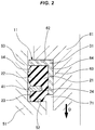
- the portion 22 of the length L 1 contacts the side wall 54 earlier than the portion 23 of the length L 2 as illustrated in FIG. 2 .
- a situation is realized in which the portion 23 of the length L 2 does not yet contact the side wall 54 even when expanding in a state where the portion 22 of the length L 1 expands and contacts the side wall 54.
- the rise (increase) of the reaction force after the contact becomes slow as illustrated in a graph of FIG. 3 . Therefore, the displacement amount until the allowable reaction force is reached increases, and thus efficient energy absorption is enabled and the absorbable energy amount can be increased.
- a metal attachment ring (not illustrated) may be bonded also to the other axial end (lower side in the figure, the rack housing 51 side) of the elastic body 21.
- the outer diameter of the elastic body 21 is formed to be smaller than the inner diameter of the side wall 54 of the rack housing 51. Therefore, radial clearances c 2 are formed between the elastic body 21 and the side wall part 54.
- a sharp rise (increase) of the reaction force is already started at the timing (point F) when the second member 41 contacts the side wall 54.
- efficient energy absorption is enabled and the absorbable energy amount can be increased.
- Comparative Example illustrates the characteristic by a damping stopper not having the second member 41.
- a sharp rise (increase) of the reaction force is started at the timing (point E) where the elastic body 21 contacts the side wall 54. Therefore, efficient energy absorption cannot be performed and the absorbable energy amount cannot be increased.
Landscapes
- Engineering & Computer Science (AREA)
- General Engineering & Computer Science (AREA)
- Mechanical Engineering (AREA)
- Combustion & Propulsion (AREA)
- Chemical & Material Sciences (AREA)
- Transportation (AREA)
- Physics & Mathematics (AREA)
- Aviation & Aerospace Engineering (AREA)
- Acoustics & Sound (AREA)
- Health & Medical Sciences (AREA)
- Child & Adolescent Psychology (AREA)
- Vibration Dampers (AREA)
- Vibration Prevention Devices (AREA)
- Springs (AREA)
- Power Steering Mechanism (AREA)
Abstract
Description
- The disclosure relates to a damping stopper stopping the displacement of a movable member, the relative displacement between members, and the like while exhibiting a damping action.
- The damping stopper is used as a rack end stopper for an end of a steering rack provided in a steering gear of a vehicle, for example. As illustrated in
FIG. 6 , the rack end stopper compresses and deforms anelastic body 82 containing a rubber material between arack housing 51 and arack 61 axially facing each other and axially displaced relative to each other. - A damping stopper 81 damps a shock when the
rack 61 collides with therack housing 51 when a steering wheel is vigorously turned to a full lock in a hydraulically/electrically assisted steering rack, for example. - The damping of the shock by the
damping stopper 81 is performed by absorbing the kinetic energy by the weight and the speed of a movable object (rack 61) by the displacement and the reaction force of the damping stopper 81 (elastic body 82). As illustrated in a graph ofFIG. 7 , the absorbable energy amount is defined by the size of an area S illustrated by a diagram obtained by the displacement amount and the reaction force of thedamping stopper 81. - Therefore, in order to increase the absorbable energy amount, it is common to enlarge the area S by increasing the displacement amount of the
damping stopper 81 or increasing the reaction force (Rigidity = Spring constant). - Patent Document 1: Japanese Unexamined Patent Application Publication No.
8-133102 - The above-described technique has room for improvement in the following points.
- The
damping stopper 81 requires a proper distortion in order to obtain a high reaction force like a nonlinear region as the characteristic of a common elastic material. In this point, the above-described structure requires an increase in the stopper size in order to satisfy a request function. However, a design space is limited due to the relationship with peripheral components, and thus the size increase is not easy. - As a solution technique for the above-described problem, it is considered to obtain a high reaction force by filling, with the
elastic body 82 which is deformed by an input, a clearance c between a mating component (housing 51) and thestopper 81. - However, according to this technique, the reaction force sharply rises when the
elastic body 82 reaches a filled state, and therefore efficient energy absorption cannot be performed. As a result, the absorbable energy amount cannot be increased. - It is an object of the disclosure to provide a damping stopper capable of increasing the absorbable energy amount.
- A damping stopper of the disclosure is provided with an elastic body provided between two members axially displaced relative to each other and, when the interval between the two members decreases, axially compressed by the two members and expanding radially outward and a second member attached to an outer periphery of the elastic body in one axial region of the elastic body and suppressing the expansion of the elastic body in the one region, in which the elastic body expands while receiving resistance by the second member to thereby contact a side wall provided in one member of the two members.
- According to the disclosure, a resistance force by the second member is generated in an expansion process of the elastic body, and thus the absorbable energy amount can be increased.
-
-
FIG. 1 is a cross-sectional view of a principal portion of a damping stopper of a first embodiment. -
FIG. 2 is a cross-sectional view of a principal portion illustrating the operation state of the damping stopper. -
FIG. 3 is a graph illustrating the relationship between the displacement amount and the reaction force in the damping stopper. -
FIG. 4 is a cross-sectional view of a principal portion of a damping stopper of a second embodiment. -
FIG. 5 is a graph illustrating the relationship between the displacement amount and the reaction force in the damping stopper. -
FIG. 6 is a cross-sectional view of a principal portion of a damping stopper described in the background art. -
FIG. 7 is a graph illustrating the relationship between the displacement amount and the reaction force in the damping stopper. - A
damping stopper 11 of this embodiment is an example of a rack end stopper of a steering rack provided in a steering gear of a vehicle. As illustrated inFIG. 1 orFIG. 4 , thedamping stopper 11 is interposed between arack housing 51 and arack 61 as two members axially facing each other and axially displaced relative to each other. - The
rack housing 51 has anend surface 52 having a planar shape perpendicular to the axis. On the outer periphery of theend surface 52, alevel difference 53 is provided. On the inner peripheral surface of thelevel difference 53, aside wall 54 is provided. Therack 61 has anend surface 62 axially facing theend surface 52 of therack housing 51. On the inner periphery of theend surface 62, alevel difference 63 is provided. On the outer peripheral surface of thelevel difference 63, aside wall 64 is provided. Therefore, anannular mounting space 71, four sides of which are surrounded by theend surface 52 and theside wall 54 of therack housing 51 and theend surface 62 and theside wall 64 of therack 61, is provided. The damping stopper 11 forms an annular shape as a whole and mounted in themounting space 71. - A first embodiment is described based on
FIG. 1 to FIG. 3 . - As illustrated in
FIG. 1 , thedamping stopper 11 has anelastic body 21 axially compressed between theend surface 52 of therack housing 51 and theend surface 62 of therack 61. - The
elastic body 21 is formed into an annular shape by a predetermined rubber material. To one axial end (upper side in the figure, therack 61 side) and the inner peripheral surface, ametal attachment ring 31 presenting an L-shaped cross section is bonded (vulcanized and bonded). As illustrated inFIG. 2 , when therack 61 is displaced in the direction of approaching the rack housing 51 (direction indicated by an arrow D) so that the interval between theend surfaces elastic body 21 is axially compressed by therack housing 51 and therack 61 and expands radially outward. - In the implementation of the disclosure, a metal attachment ring (not illustrated) may be bonded also to the other axial end (lower side in the figure, the rack housing 51 side) of the
elastic body 21. - The
damping stopper 11 has asecond member 41 attached to one axial part of the outer periphery in theelastic body 21 and restricting the expansion of theelastic body 21 in the one axial part. More specifically, thesecond member 41 is attached to the outer periphery of theelastic body 21 in one axial region of theelastic body 21 and suppresses the expansion of theelastic body 21 in the one region. - The
second member 41 is a ring body having rigidity such that thesecond member 41 does not contact theside wall 54 when theelastic body 21 expanding radially outward contacts theside wall 54. The ring body is formed of metal as an example and formed of resin as another example. The ring body has a shape in which the dimension in a direction orthogonal to the axis is larger than the axial dimension and is assembled to anannular mounting groove 24 provided in theelastic body 21. Themounting groove 24 is a groove provided beforehand in the outer peripheral surface of theelastic body 21. - The
mounting groove 24 is formed at a position where theelastic body 21 is divided into aportion 22 of a length L1 and aportion 23 of a length L2. Therefore, the ring body configuring thesecond member 41 is attached to a position where theelastic body 21 is divided into theportion 22 of the length L1 having a long axial length and theportion 23 of the length L2 having a short axial length. It is needless to say that the axial length does not have an absolutely long-and-short relationship and has a relatively long-and-short relationship between theportions elastic body 21. - As another embodiment, in order to facilitate the assembling work to the
mounting groove 24, the annularsecond member 41 may be provided with a cut portion or the like in one place on the circumference. Moreover, thesecond member 41 may be buried in theelastic body 21 by carrying out insert molding in the vulcanization molding of theelastic body 21 by a mold. Considering the function or the like thereof, thesecond member 41 is also referred to as a resistance member or also referred to as an elastic body clamping member. - The outer diameter of the
second member 41 is formed to be larger than the outer diameter of theelastic body 21. Therefore, thesecond member 41 is projected radially outward from the outer peripheral surface of theelastic body 21. - The outer diameter of the
second member 41 is formed to be smaller than the inner diameter of theside wall 54 of therack housing 51. Therefore, a radial clearance c1 is formed between thesecond member 41 and theside wall 54. However, thesecond member 41 does not expand, and therefore it may be also structured so that the outer diameter of thesecond member 41 is set to be equal to the inner diameter of theside wall 54 so that thesecond member 41 is brought into contact with theside wall 54. - The outer diameter of the
elastic body 21 is formed to be smaller than the inner diameter of theside wall 54 of therack housing 51, and therefore radial clearances c2 are formed between theelastic body 21 and theside wall 54. - In the damping
stopper 11 of this embodiment, when therack 61 is displaced in the direction of approaching the rack housing 51 (arrow D) so that the interval between the end surfaces 52 and 62 decreases, theelastic body 21 is axially compressed between therack housing 51 and therack 61 and expands radially outward corresponding to the compression. Thesecond member 41 is attached to one axial part of the outer periphery of theelastic body 21, and therefore acts as a resistance element to the expansion of theelastic body 21. As a result, the radially outward expansion of theelastic body 21 is restricted in the one axial part. - As described above, the
elastic body 21 is divided into theportion 22 of the length L1 having a long axial length and theportion 23 of the length L2 having a short axial length. Theelastic body 21 expands in both theportions - When the
portion 22 of the length L1 having a long axial length and theportion 23 of the length L2 having a short axial length are compared, theportion 22 of the length L1 has a surface area larger than that of theportion 23 of the length L2 and more greatly extends radially outward than theportion 23 of the length L2. As a result, theportion 22 of the length L1 contacts theside wall 54 earlier than theportion 23 of the length L2 as illustrated inFIG. 2 . Then, a situation is realized in which theportion 23 of the length L2 does not yet contact theside wall 54 even when expanding in a state where theportion 22 of the length L1 expands and contacts theside wall 54. - Accordingly, the rise (increase) of the reaction force after the contact becomes slow as illustrated in a graph of
FIG. 3 . Therefore, the displacement amount until the allowable reaction force is reached increases, and thus efficient energy absorption is enabled and the absorbable energy amount can be increased. - In the graph of
FIG. 3 , Comparative Example illustrates a damping stopper of a conventional structure not having thesecond member 41 and the reaction force sharply rises after contact in Comparative Example, and therefore the displacement amount is small. A point E indicates the timing when theelastic body 21 contacts theside wall 54. - A second embodiment is described based on
FIG. 4 andFIG. 5 . The same portions as those of the first embodiment are designated by the same reference numerals and a description thereof is omitted. - As illustrated in
FIG. 4 , a dampingstopper 11 has anelastic body 21 axially compressed between anend surface 52 of arack housing 51 and anend surface 62 of arack 61. - The
elastic body 21 is formed into an annular shape by a predetermined rubber material. To one axial end (upper side in the figure, therack 61 side) and the inner peripheral surface, ametal attachment ring 31 presenting an L-shaped cross section is bonded (vulcanized and bonded). When therack 61 is displaced in the direction of approaching therack housing 51 so that the interval between the end surfaces 52 and 62 decreases, theelastic body 21 is axially compressed by therack housing 51 and therack 61 and expands radially outward. - In the implementation of the disclosure, a metal attachment ring (not illustrated) may be bonded also to the other axial end (lower side in the figure, the
rack housing 51 side) of theelastic body 21. - The damping
stopper 11 has asecond member 41 attached to one axial part of the outer periphery of theelastic body 21 and restricting the expansion of theelastic body 21 in the one axial part. More specifically, thesecond member 41 is attached to the outer periphery of theelastic body 21 in one axial region of theelastic body 21 and suppresses the expansion of theelastic body 21 in the one region. - The
second member 41 is a ring body having elasticity such that thesecond member 41 expands radially outward when pressed by theelastic body 21 expanding radially outward and rigidity higher than that of theelastic body 21 such that thesecond member 41 contacts aside wall 54 earlier than theelastic body 21. The ring body having such a characteristic has rigidity higher than that of theelastic body 21 by being formed of a material different from that of theelastic body 21. As an example, thesecond member 41 is formed of urethane. - As another embodiment, in order to facilitate the assembling work to a mounting
groove 24, the ring body configuring thesecond member 41 may be provided with a cut portion in one place on the circumference. Alternatively, the ring body may be divided into two parts on the circumference to have a halved structure. Considering the function or the like thereof, thesecond member 41 is also referred to as a resistance member or also referred to as an elastic body clamping member. - The outer diameter of the
second member 41 is formed to be larger than the outer diameter of theelastic body 21. Therefore, thesecond member 41 is projected radially outward from the outer peripheral surface of theelastic body 21. - The outer diameter of the
second member 41 is formed to be smaller than the inner diameter of theside wall 54 of therack housing 51. Therefore, a radial clearance c1 is formed between thesecond member 41 and theside wall 54. - The outer diameter of the
elastic body 21 is formed to be smaller than the inner diameter of theside wall 54 of therack housing 51. Therefore, radial clearances c2 are formed between theelastic body 21 and theside wall part 54. - In the damping
stopper 11 of this embodiment, when therack 61 is displaced in the direction of approaching therack housing 51 so that the interval between the end surfaces 52 and 62 decreases, theelastic body 21 is axially compressed between therack housing 51 and therack 61 and expands radially outward corresponding to the compression. Thesecond member 41 is attached to one axial part of the outer periphery of theelastic body 21, and therefore acts as a resistance element to the expansion. As a result, the radially outward expansion of theelastic body 21 is restricted in the one axial part. - When the
elastic body 21 continuously expands in response to a load accompanying the displacement of therack 61, the pressure by the expansion presses thesecond member 41 radially outward and expands thesecond member 41 radially outward (diameter enlarging deformation) to bring thesecond member 41 into contact with theside wall 54. In order to expand thesecond member 41 radially outward to bring thesecond member 41 into contact with theside wall 54, a large load is required. Therefore, the rigidity of the entire dampingstopper 11 is increased, so that a high reaction force as compared with that in the case where theelastic body 21 is used alone is generated - Thereafter, when the
rack 61 is displaced in the direction of further approaching therack housing 51 in the state where thesecond member 41 contacts theside wall 54, thesecond member 41 slides against theside wall 54, so that sliding resistance is generated between thesecond member 41 and theside wall 54. The rigidity is increased by the sliding resistance, so that a higher reaction force is generated. - As illustrated in a graph of
FIG. 5 , according to the dampingstopper 11 of this embodiment, a sharp rise (increase) of the reaction force is already started at the timing (point F) when thesecond member 41 contacts theside wall 54. Thus, efficient energy absorption is enabled and the absorbable energy amount can be increased. - In the graph of
FIG. 5 , Comparative Example illustrates the characteristic by a damping stopper not having thesecond member 41. In Comparative Example, a sharp rise (increase) of the reaction force is started at the timing (point E) where theelastic body 21 contacts theside wall 54. Therefore, efficient energy absorption cannot be performed and the absorbable energy amount cannot be increased. -
- 11
- damping stopper
- 21
- elastic body
- 22
- portion having relatively long axial length
- 23
- portion having relatively short axial length
- 24
- mounting groove
- 31
- attachment ring
- 41
- second member
- 51
- rack housing
- 52, 62
- end surface
- 53, 63
- level difference
- 54, 64
- side wall
- 61
- rack
- 71
- mounting space
- c1, c2
- radial clearance
Claims (7)
- A damping stopper comprising:an elastic body provided between two members axially displaced relative to each other and, when an interval between the two members decreases, axially compressed by the two members and expanding radially outward; anda second member attached to an outer periphery of the elastic body in one axial region of the elastic body and suppressing expansion of the elastic body in the one region, whereinthe elastic body expands while receiving resistance by the second member to thereby contact a side wall provided in one member of the two members.
- The damping stopper according to Claim 1, wherein
the second member is a ring body having rigidity such that the second member does not contact the side wall when the elastic body expanding radially outward contacts the side wall. - The damping stopper according to Claim 2, wherein
the ring body has a shape in which a dimension in a direction orthogonal to an axis is larger than an axial dimension. - The damping stopper according to Claim 3, wherein
the ring body is assembled to an annular mounting groove provided in the elastic body. - The damping stopper according to any one of Claims 2 to 4, wherein
the ring body is attached to a position where the elastic body is divided into a portion having a long axial length and a portion having a short axial length. - The damping stopper according to Claim 1, wherein
the second member has elasticity such that the second member expands radially outward when pressed by the elastic body expanding radially outward and rigidity higher than rigidity of the elastic body such that the second member contacts the side wall earlier than the elastic body. - The damping stopper according to Claim 6, wherein
the second member is a ring body.
Applications Claiming Priority (2)
| Application Number | Priority Date | Filing Date | Title |
|---|---|---|---|
| JP2017240274 | 2017-12-15 | ||
| PCT/JP2018/043480 WO2019116878A1 (en) | 2017-12-15 | 2018-11-27 | Damping stopper |
Publications (4)
| Publication Number | Publication Date |
|---|---|
| EP3726091A1 true EP3726091A1 (en) | 2020-10-21 |
| EP3726091A4 EP3726091A4 (en) | 2021-08-25 |
| EP3726091B1 EP3726091B1 (en) | 2025-06-25 |
| EP3726091C0 EP3726091C0 (en) | 2025-06-25 |
Family
ID=66819605
Family Applications (1)
| Application Number | Title | Priority Date | Filing Date |
|---|---|---|---|
| EP18889488.5A Active EP3726091B1 (en) | 2017-12-15 | 2018-11-27 | Damping stopper |
Country Status (5)
| Country | Link |
|---|---|
| US (2) | US20200370618A1 (en) |
| EP (1) | EP3726091B1 (en) |
| JP (1) | JP6957642B2 (en) |
| CN (2) | CN120592993A (en) |
| WO (1) | WO2019116878A1 (en) |
Families Citing this family (1)
| Publication number | Priority date | Publication date | Assignee | Title |
|---|---|---|---|---|
| US10988171B2 (en) * | 2019-04-04 | 2021-04-27 | Honda Motor Co., Ltd. | Steering rack stopper |
Family Cites Families (13)
| Publication number | Priority date | Publication date | Assignee | Title |
|---|---|---|---|---|
| JP3231959B2 (en) * | 1994-11-07 | 2001-11-26 | 本田技研工業株式会社 | Stroke end shock absorber for steering mechanism |
| JP2001271864A (en) * | 2000-03-24 | 2001-10-05 | Tokai Rubber Ind Ltd | Bound stopper |
| JP4362439B2 (en) * | 2004-12-17 | 2009-11-11 | 東海ゴム工業株式会社 | Bound stopper for suspension device |
| DE102009019890A1 (en) | 2009-05-04 | 2010-11-11 | Trw Automotive Gmbh | Rack and pinion steering |
| JP6413329B2 (en) | 2013-12-03 | 2018-10-31 | 株式会社ジェイテクト | Steering device |
| JP6364186B2 (en) * | 2013-12-10 | 2018-07-25 | 株式会社ショーワ | Steering device |
| CN203666761U (en) * | 2014-01-08 | 2014-06-25 | 中国第一汽车股份有限公司 | Steering gear limiting block |
| JP2015186950A (en) * | 2014-03-26 | 2015-10-29 | 株式会社ジェイテクト | steering device |
| JP6209114B2 (en) | 2014-03-26 | 2017-10-04 | 株式会社ショーワ | Steering device |
| JP2016008003A (en) * | 2014-06-26 | 2016-01-18 | 株式会社ジェイテクト | Steering device |
| JP6462391B2 (en) * | 2015-02-09 | 2019-01-30 | Nok株式会社 | Buffer stopper |
| JP6479495B2 (en) * | 2015-02-09 | 2019-03-06 | Nok株式会社 | Buffer stopper |
| JP6534907B2 (en) | 2015-10-22 | 2019-06-26 | 株式会社ジェイテクト | Damper apparatus and steering apparatus |
-
2018
- 2018-11-27 CN CN202511039543.9A patent/CN120592993A/en active Pending
- 2018-11-27 EP EP18889488.5A patent/EP3726091B1/en active Active
- 2018-11-27 US US16/767,620 patent/US20200370618A1/en not_active Abandoned
- 2018-11-27 WO PCT/JP2018/043480 patent/WO2019116878A1/en not_active Ceased
- 2018-11-27 CN CN201880074303.4A patent/CN111356859A/en active Pending
- 2018-11-27 JP JP2019559526A patent/JP6957642B2/en active Active
-
2023
- 2023-03-22 US US18/187,973 patent/US11988262B2/en active Active
Also Published As
| Publication number | Publication date |
|---|---|
| US20230228314A1 (en) | 2023-07-20 |
| EP3726091B1 (en) | 2025-06-25 |
| WO2019116878A1 (en) | 2019-06-20 |
| EP3726091C0 (en) | 2025-06-25 |
| US11988262B2 (en) | 2024-05-21 |
| JP6957642B2 (en) | 2021-11-02 |
| CN120592993A (en) | 2025-09-05 |
| US20200370618A1 (en) | 2020-11-26 |
| EP3726091A4 (en) | 2021-08-25 |
| CN111356859A (en) | 2020-06-30 |
| JPWO2019116878A1 (en) | 2020-12-24 |
Similar Documents
| Publication | Publication Date | Title |
|---|---|---|
| JP5400929B2 (en) | Vibration isolator | |
| JP6510893B2 (en) | Buffer stopper | |
| CN105765263B (en) | Vehicular dust cover assembly and method for manufacturing same | |
| WO2015045750A1 (en) | Cylindrical vibration isolator | |
| KR20060130761A (en) | Reciprocating Shaft Sealing Device | |
| US11988262B2 (en) | Damping stopper | |
| US20170144504A1 (en) | Energy Management Jounce Bumper Assembly | |
| JP2017219143A (en) | Gear damper and process of manufacture thereof | |
| JPH1182626A (en) | Device for flexibly connecting at least two component parts | |
| JP2018071768A (en) | Vibration isolator | |
| CN110529545B (en) | Liquid-filled vibration-proof device | |
| JP2014062560A (en) | Dust cover assembly for vehicle and method of manufacturing the same | |
| EP2910812A1 (en) | Rebound rubber | |
| JP6987008B2 (en) | Buffer stopper | |
| JP6510872B2 (en) | Buffer stopper | |
| JP6449027B2 (en) | Buffer stopper | |
| JP4935997B2 (en) | Piston for hydraulic clutch | |
| JP7142509B2 (en) | buffer stopper | |
| EP1338821B1 (en) | Dynamic damper and propeller shaft | |
| US20250129832A1 (en) | Cushioning stopper | |
| JP2019100371A (en) | Buffer stopper | |
| RU2662317C2 (en) | Elastic element | |
| CN109099159B (en) | Sealing protective cover | |
| GB2579245A (en) | Vibrating flange assembly | |
| WO2018024500A1 (en) | Top suspension mount comprising a securing element in relation to a vehicle body, assembly comprising such a mount, and process for joining such a mount to a vehicle body |
Legal Events
| Date | Code | Title | Description |
|---|---|---|---|
| STAA | Information on the status of an ep patent application or granted ep patent |
Free format text: STATUS: THE INTERNATIONAL PUBLICATION HAS BEEN MADE |
|
| PUAI | Public reference made under article 153(3) epc to a published international application that has entered the european phase |
Free format text: ORIGINAL CODE: 0009012 |
|
| STAA | Information on the status of an ep patent application or granted ep patent |
Free format text: STATUS: REQUEST FOR EXAMINATION WAS MADE |
|
| 17P | Request for examination filed |
Effective date: 20200529 |
|
| AK | Designated contracting states |
Kind code of ref document: A1 Designated state(s): AL AT BE BG CH CY CZ DE DK EE ES FI FR GB GR HR HU IE IS IT LI LT LU LV MC MK MT NL NO PL PT RO RS SE SI SK SM TR |
|
| AX | Request for extension of the european patent |
Extension state: BA ME |
|
| DAV | Request for validation of the european patent (deleted) | ||
| DAX | Request for extension of the european patent (deleted) | ||
| A4 | Supplementary search report drawn up and despatched |
Effective date: 20210728 |
|
| RIC1 | Information provided on ipc code assigned before grant |
Ipc: F16F 7/00 20060101AFI20210722BHEP Ipc: B62D 3/12 20060101ALI20210722BHEP Ipc: F16F 9/58 20060101ALI20210722BHEP Ipc: F16F 15/08 20060101ALI20210722BHEP |
|
| STAA | Information on the status of an ep patent application or granted ep patent |
Free format text: STATUS: EXAMINATION IS IN PROGRESS |
|
| 17Q | First examination report despatched |
Effective date: 20221116 |
|
| REG | Reference to a national code |
Ref country code: DE Free format text: PREVIOUS MAIN CLASS: F16F0007000000 Ref country code: DE Ref legal event code: R079 Ref document number: 602018083025 Country of ref document: DE Free format text: PREVIOUS MAIN CLASS: F16F0007000000 Ipc: F16F0001360000 |
|
| GRAP | Despatch of communication of intention to grant a patent |
Free format text: ORIGINAL CODE: EPIDOSNIGR1 |
|
| STAA | Information on the status of an ep patent application or granted ep patent |
Free format text: STATUS: GRANT OF PATENT IS INTENDED |
|
| RIC1 | Information provided on ipc code assigned before grant |
Ipc: B62D 3/12 20060101ALI20250305BHEP Ipc: F16F 1/371 20060101ALI20250305BHEP Ipc: F16F 1/36 20060101AFI20250305BHEP |
|
| INTG | Intention to grant announced |
Effective date: 20250408 |
|
| GRAS | Grant fee paid |
Free format text: ORIGINAL CODE: EPIDOSNIGR3 |
|
| GRAA | (expected) grant |
Free format text: ORIGINAL CODE: 0009210 |
|
| STAA | Information on the status of an ep patent application or granted ep patent |
Free format text: STATUS: THE PATENT HAS BEEN GRANTED |
|
| AK | Designated contracting states |
Kind code of ref document: B1 Designated state(s): AL AT BE BG CH CY CZ DE DK EE ES FI FR GB GR HR HU IE IS IT LI LT LU LV MC MK MT NL NO PL PT RO RS SE SI SK SM TR |
|
| REG | Reference to a national code |
Ref country code: GB Ref legal event code: FG4D |
|
| REG | Reference to a national code |
Ref country code: CH Ref legal event code: EP |
|
| REG | Reference to a national code |
Ref country code: CH Ref legal event code: EP |
|
| REG | Reference to a national code |
Ref country code: IE Ref legal event code: FG4D |
|
| U01 | Request for unitary effect filed |
Effective date: 20250627 |
|
| U07 | Unitary effect registered |
Designated state(s): AT BE BG DE DK EE FI FR IT LT LU LV MT NL PT RO SE SI Effective date: 20250703 |
|
| PG25 | Lapsed in a contracting state [announced via postgrant information from national office to epo] |
Ref country code: GR Free format text: LAPSE BECAUSE OF FAILURE TO SUBMIT A TRANSLATION OF THE DESCRIPTION OR TO PAY THE FEE WITHIN THE PRESCRIBED TIME-LIMIT Effective date: 20250926 Ref country code: NO Free format text: LAPSE BECAUSE OF FAILURE TO SUBMIT A TRANSLATION OF THE DESCRIPTION OR TO PAY THE FEE WITHIN THE PRESCRIBED TIME-LIMIT Effective date: 20250925 |
|
| PG25 | Lapsed in a contracting state [announced via postgrant information from national office to epo] |
Ref country code: HR Free format text: LAPSE BECAUSE OF FAILURE TO SUBMIT A TRANSLATION OF THE DESCRIPTION OR TO PAY THE FEE WITHIN THE PRESCRIBED TIME-LIMIT Effective date: 20250625 |
|
| PG25 | Lapsed in a contracting state [announced via postgrant information from national office to epo] |
Ref country code: RS Free format text: LAPSE BECAUSE OF FAILURE TO SUBMIT A TRANSLATION OF THE DESCRIPTION OR TO PAY THE FEE WITHIN THE PRESCRIBED TIME-LIMIT Effective date: 20250925 |
|
| U20 | Renewal fee for the european patent with unitary effect paid |
Year of fee payment: 8 Effective date: 20251008 |
|
| PG25 | Lapsed in a contracting state [announced via postgrant information from national office to epo] |
Ref country code: IS Free format text: LAPSE BECAUSE OF FAILURE TO SUBMIT A TRANSLATION OF THE DESCRIPTION OR TO PAY THE FEE WITHIN THE PRESCRIBED TIME-LIMIT Effective date: 20251025 |
|
| PGFP | Annual fee paid to national office [announced via postgrant information from national office to epo] |
Ref country code: GB Payment date: 20251001 Year of fee payment: 8 |
|
| PG25 | Lapsed in a contracting state [announced via postgrant information from national office to epo] |
Ref country code: SM Free format text: LAPSE BECAUSE OF FAILURE TO SUBMIT A TRANSLATION OF THE DESCRIPTION OR TO PAY THE FEE WITHIN THE PRESCRIBED TIME-LIMIT Effective date: 20250625 |
|
| PG25 | Lapsed in a contracting state [announced via postgrant information from national office to epo] |
Ref country code: CZ Free format text: LAPSE BECAUSE OF FAILURE TO SUBMIT A TRANSLATION OF THE DESCRIPTION OR TO PAY THE FEE WITHIN THE PRESCRIBED TIME-LIMIT Effective date: 20250625 |
|
| PG25 | Lapsed in a contracting state [announced via postgrant information from national office to epo] |
Ref country code: PL Free format text: LAPSE BECAUSE OF FAILURE TO SUBMIT A TRANSLATION OF THE DESCRIPTION OR TO PAY THE FEE WITHIN THE PRESCRIBED TIME-LIMIT Effective date: 20250625 |
|
| PG25 | Lapsed in a contracting state [announced via postgrant information from national office to epo] |
Ref country code: SK Free format text: LAPSE BECAUSE OF FAILURE TO SUBMIT A TRANSLATION OF THE DESCRIPTION OR TO PAY THE FEE WITHIN THE PRESCRIBED TIME-LIMIT Effective date: 20250625 |
|
| PG25 | Lapsed in a contracting state [announced via postgrant information from national office to epo] |
Ref country code: ES Free format text: LAPSE BECAUSE OF FAILURE TO SUBMIT A TRANSLATION OF THE DESCRIPTION OR TO PAY THE FEE WITHIN THE PRESCRIBED TIME-LIMIT Effective date: 20250625 |
|
| PLBE | No opposition filed within time limit |
Free format text: ORIGINAL CODE: 0009261 |
|
| STAA | Information on the status of an ep patent application or granted ep patent |
Free format text: STATUS: NO OPPOSITION FILED WITHIN TIME LIMIT |
|
| REG | Reference to a national code |
Ref country code: CH Ref legal event code: L10 Free format text: ST27 STATUS EVENT CODE: U-0-0-L10-L00 (AS PROVIDED BY THE NATIONAL OFFICE) Effective date: 20260507 |