EP3726082A1 - Inside out flexible coupling assembly - Google Patents
Inside out flexible coupling assembly Download PDFInfo
- Publication number
- EP3726082A1 EP3726082A1 EP19209761.6A EP19209761A EP3726082A1 EP 3726082 A1 EP3726082 A1 EP 3726082A1 EP 19209761 A EP19209761 A EP 19209761A EP 3726082 A1 EP3726082 A1 EP 3726082A1
- Authority
- EP
- European Patent Office
- Prior art keywords
- leg
- circular disk
- coupling assembly
- flexible coupling
- outer diameter
- Prior art date
- Legal status (The legal status is an assumption and is not a legal conclusion. Google has not performed a legal analysis and makes no representation as to the accuracy of the status listed.)
- Granted
Links
Images


Classifications
-
- F—MECHANICAL ENGINEERING; LIGHTING; HEATING; WEAPONS; BLASTING
- F16—ENGINEERING ELEMENTS AND UNITS; GENERAL MEASURES FOR PRODUCING AND MAINTAINING EFFECTIVE FUNCTIONING OF MACHINES OR INSTALLATIONS; THERMAL INSULATION IN GENERAL
- F16D—COUPLINGS FOR TRANSMITTING ROTATION; CLUTCHES; BRAKES
- F16D3/00—Yielding couplings, i.e. with means permitting movement between the connected parts during the drive
- F16D3/50—Yielding couplings, i.e. with means permitting movement between the connected parts during the drive with the coupling parts connected by one or more intermediate members
- F16D3/72—Yielding couplings, i.e. with means permitting movement between the connected parts during the drive with the coupling parts connected by one or more intermediate members with axially-spaced attachments to the coupling parts
-
- F—MECHANICAL ENGINEERING; LIGHTING; HEATING; WEAPONS; BLASTING
- F16—ENGINEERING ELEMENTS AND UNITS; GENERAL MEASURES FOR PRODUCING AND MAINTAINING EFFECTIVE FUNCTIONING OF MACHINES OR INSTALLATIONS; THERMAL INSULATION IN GENERAL
- F16D—COUPLINGS FOR TRANSMITTING ROTATION; CLUTCHES; BRAKES
- F16D3/00—Yielding couplings, i.e. with means permitting movement between the connected parts during the drive
- F16D3/50—Yielding couplings, i.e. with means permitting movement between the connected parts during the drive with the coupling parts connected by one or more intermediate members
- F16D3/72—Yielding couplings, i.e. with means permitting movement between the connected parts during the drive with the coupling parts connected by one or more intermediate members with axially-spaced attachments to the coupling parts
- F16D3/74—Yielding couplings, i.e. with means permitting movement between the connected parts during the drive with the coupling parts connected by one or more intermediate members with axially-spaced attachments to the coupling parts the intermediate member or members being made of rubber or other rubber-like flexible material
-
- F—MECHANICAL ENGINEERING; LIGHTING; HEATING; WEAPONS; BLASTING
- F16—ENGINEERING ELEMENTS AND UNITS; GENERAL MEASURES FOR PRODUCING AND MAINTAINING EFFECTIVE FUNCTIONING OF MACHINES OR INSTALLATIONS; THERMAL INSULATION IN GENERAL
- F16C—SHAFTS; FLEXIBLE SHAFTS; ELEMENTS OR CRANKSHAFT MECHANISMS; ROTARY BODIES OTHER THAN GEARING ELEMENTS; BEARINGS
- F16C1/00—Flexible shafts; Mechanical means for transmitting movement in a flexible sheathing
- F16C1/02—Flexible shafts; Mechanical means for transmitting movement in a flexible sheathing for conveying rotary movements
- F16C1/08—End connections
-
- F—MECHANICAL ENGINEERING; LIGHTING; HEATING; WEAPONS; BLASTING
- F16—ENGINEERING ELEMENTS AND UNITS; GENERAL MEASURES FOR PRODUCING AND MAINTAINING EFFECTIVE FUNCTIONING OF MACHINES OR INSTALLATIONS; THERMAL INSULATION IN GENERAL
- F16C—SHAFTS; FLEXIBLE SHAFTS; ELEMENTS OR CRANKSHAFT MECHANISMS; ROTARY BODIES OTHER THAN GEARING ELEMENTS; BEARINGS
- F16C2326/00—Articles relating to transporting
- F16C2326/01—Parts of vehicles in general
- F16C2326/06—Drive shafts
-
- F—MECHANICAL ENGINEERING; LIGHTING; HEATING; WEAPONS; BLASTING
- F16—ENGINEERING ELEMENTS AND UNITS; GENERAL MEASURES FOR PRODUCING AND MAINTAINING EFFECTIVE FUNCTIONING OF MACHINES OR INSTALLATIONS; THERMAL INSULATION IN GENERAL
- F16D—COUPLINGS FOR TRANSMITTING ROTATION; CLUTCHES; BRAKES
- F16D2300/00—Special features for couplings or clutches
-
- F—MECHANICAL ENGINEERING; LIGHTING; HEATING; WEAPONS; BLASTING
- F16—ENGINEERING ELEMENTS AND UNITS; GENERAL MEASURES FOR PRODUCING AND MAINTAINING EFFECTIVE FUNCTIONING OF MACHINES OR INSTALLATIONS; THERMAL INSULATION IN GENERAL
- F16D—COUPLINGS FOR TRANSMITTING ROTATION; CLUTCHES; BRAKES
- F16D2300/00—Special features for couplings or clutches
- F16D2300/12—Mounting or assembling
Definitions
- the present disclosure relates to drive shafts and flexible couplings, and more particularly to an inside out flexible coupling.
- a flexible coupling assembly for a power transmission system includes a first circular disk and a second circular disk defining an outer diameter and an inner diameter, wherein the first circular disk and the second circular disk are connected a location on the outer diameter and disconnected at the inner diameter, wherein the first and second circular disks includes a central portion connecting the outer diameter and the inner diameter, wherein the central portion includes a narrowing section and a widening section in a radial direction away from the inner diameter.
- the first disk and the second disk are welded together.
- the first circular disk is configured to connect to a first rotating member interface
- the second circular disk is configured to connect to a second rotating member interface.
- the outer diameter can be the radially outermost point of the assembly.
- a boundary between the first and second circular disks can include a smooth cylindrical outer surface.
- the connection or boundary of the first and second circular disks can include a venting through hole.
- the first circular disk and the second circular disk can be surrounded by a protective sleeve.
- the first circular disk can include two circular sections separated at the outer diameter and the two circular sections can be connected at a hub at the inner diameter.
- the first and second circular disk each include a protrusion at the outer diameter for connecting to an adjacent disk or adjacent rotating member.
- the circular first disk and the second circular disk can each include a U-shaped cross section.
- the first and second circular disks can be identical.
- Fig. 1 a partial view of an exemplary embodiment of a flexible coupling in accordance with the invention is shown in Fig. 1 and is designated generally by reference character 100.
- Other embodiments of flexible coupling in accordance with the invention, or aspects thereof, are provided in Figs. 2-3 , as will be described.
- the methods and systems of the invention can be used to protect the flexible coupling in operation and to decrease the weight of the flexible coupling.
- the flexible coupling assembly 100 includes a first circular disk 102 defining a u-shaped radial cross-section 104 including a first leg 106 and a second leg 108 connected at an inner diameter D1 thereof circumscribing an axial bore 110 of the flexible coupling assembly 100 and disconnected at an outer diameter D2 of the first circular disk 102 configured to connect to a first rotating member interface 112, and a second circular disk 103 defining a u-shaped radial cross-section 105 including a first leg 107 and a second leg 109 connected at an inner diameter D1 thereof circumscribing the axial bore 110 of the flexible coupling assembly 100 and disconnected at an outer diameter D2 of the second circular disk 103 configured to connect to a second rotating member interface 113.
- the first leg 106 and the second leg 108 of the first circular disk 102 each include a portion 114 having an axial width W1 of a cross section varying over a radial direction.
- the portion 114 connects a protrusion 116 located at the outer diameter D2 and a hub 118 located at the inner diameter D1 which connects the first leg 104 and the second leg 106 of the first circular disk 102.
- the first leg 105 and the second leg 107 of the second circular disk 103 each include a portion 115 having an axial width W2 of a cross section varying over a radial direction connecting a protrusion 117 at the outer diameter D2 and the hub 118 located at the inner diameter D1 connecting the first leg 105 and second leg 107 of the second circular disk 103.
- the narrowest point 120 of each disk is approximately 2/3 of the distance from the inner diameter D2 to the outer diameter D1.
- the first disk 102 and the second disk 103 are welded together.
- the first and second circular disks can be identical. It is also conceived the disks can include different profiles based on the design requirements.
- the U-shaped disks can be manufactured using conventional machining then mated together by welding.
- the outer diameter D2 of the assembly 100 is flush with at least one of the attached interfaces 112, 113.
- the outer diameter D2 of the assembly is flush with both the first rotating member interface 112 and the second rotating member interface 113.
- An important feature of this disclorsure is having the critical areas of the first circular disk 102 and the second circular disk 103 be enclosed and protected by the protrusions 116 and 117.
- Each of the disks include two protrusions, for attaching to either the adjacent disk or to the adjacent interface. The protrusions ensure that debris or tools do not strike the flexible members.
- a reinforcing section 130 is included at the outermost portion of each disk, ensuring that all flexing within the disks is accommodated within the profile and not the welded joints. The reinforcing section is wider than the rest of the portion connecting the hubs and protrusions.
- a boundary between the first 102 and second 103 circular disks includes a smooth cylindrical outer surface.
- the connection or boundary of the first and second circular disks includes a venting through holes 125.
- the venting holes 125 can be evenly spaced around the circumference of the disks 102, 103. The venting holes 125 ensure that gasses and liquids are not trapped and do not cause further stresses or corrosion on the inner portion of the flexible shaft.
Landscapes
- Engineering & Computer Science (AREA)
- General Engineering & Computer Science (AREA)
- Mechanical Engineering (AREA)
- Health & Medical Sciences (AREA)
- Oral & Maxillofacial Surgery (AREA)
- General Details Of Gearings (AREA)
- Flexible Shafts (AREA)
Abstract
Description
- The present disclosure relates to drive shafts and flexible couplings, and more particularly to an inside out flexible coupling.
- A variety of devices are known in the flexible coupling field. The conventional methods and systems have generally been considered satisfactory for their intended purpose. Traditional designs the end protrusions and adapters attach to the inner diameter of the flexible members. There is still a need in the art for a flexible coupling that is lighter and has a lower manufacturing cost. The present disclosure may provide a solution for at least one of these remaining challenges.
- A flexible coupling assembly for a power transmission system includes a first circular disk and a second circular disk defining an outer diameter and an inner diameter, wherein the first circular disk and the second circular disk are connected a location on the outer diameter and disconnected at the inner diameter, wherein the first and second circular disks includes a central portion connecting the outer diameter and the inner diameter, wherein the central portion includes a narrowing section and a widening section in a radial direction away from the inner diameter. The first disk and the second disk are welded together. The first circular disk is configured to connect to a first rotating member interface, and the second circular disk is configured to connect to a second rotating member interface.
- The outer diameter can be the radially outermost point of the assembly. A boundary between the first and second circular disks can include a smooth cylindrical outer surface. The connection or boundary of the first and second circular disks can include a venting through hole.
- The first circular disk and the second circular disk can be surrounded by a protective sleeve.
- The first circular disk can include two circular sections separated at the outer diameter and the two circular sections can be connected at a hub at the inner diameter. The first and second circular disk each include a protrusion at the outer diameter for connecting to an adjacent disk or adjacent rotating member. The circular first disk and the second circular disk can each include a U-shaped cross section. The first and second circular disks can be identical.
- These and other features of the systems and methods of the subject disclosure will become more readily apparent to those skilled in the art from the following detailed description of the preferred embodiments taken in conjunction with the drawings.
- So that those skilled in the art to which the subject invention appertains will readily understand how to make and use the devices and methods of the subject invention without undue experimentation, preferred embodiments thereof will be described in detail herein below with reference to certain figures, wherein:
-
Fig. 1 is a cross section perspective view of a flexible coupling showing the profile of the disks; -
Fig. 2 is a side view ofFig. 1 , showing the interaction of the disks and the rotational member interfaces; and -
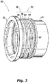
Fig. 3 is a perspective view of the outside ofFig. 1 , showing the outer surface of the flexible coupling. - Reference will now be made to the drawings wherein like reference numerals identify similar structural features or aspects of the subject invention. For purposes of explanation and illustration, and not limitation, a partial view of an exemplary embodiment of a flexible coupling in accordance with the invention is shown in
Fig. 1 and is designated generally byreference character 100. Other embodiments of flexible coupling in accordance with the invention, or aspects thereof, are provided inFigs. 2-3 , as will be described. The methods and systems of the invention can be used to protect the flexible coupling in operation and to decrease the weight of the flexible coupling. - Referring to
Fig. 1 , theflexible coupling assembly 100 includes a firstcircular disk 102 defining a u-shapedradial cross-section 104 including afirst leg 106 and asecond leg 108 connected at an inner diameter D1 thereof circumscribing anaxial bore 110 of theflexible coupling assembly 100 and disconnected at an outer diameter D2 of the firstcircular disk 102 configured to connect to a first rotatingmember interface 112, and a secondcircular disk 103 defining a u-shapedradial cross-section 105 including afirst leg 107 and asecond leg 109 connected at an inner diameter D1 thereof circumscribing theaxial bore 110 of theflexible coupling assembly 100 and disconnected at an outer diameter D2 of the secondcircular disk 103 configured to connect to a second rotatingmember interface 113. - Referring to
Fig. 2 , thefirst leg 106 and thesecond leg 108 of the firstcircular disk 102 each include a portion 114 having an axial width W1 of a cross section varying over a radial direction. The portion 114 connects aprotrusion 116 located at the outer diameter D2 and ahub 118 located at the inner diameter D1 which connects thefirst leg 104 and thesecond leg 106 of the firstcircular disk 102. Thefirst leg 105 and thesecond leg 107 of the secondcircular disk 103 each include aportion 115 having an axial width W2 of a cross section varying over a radial direction connecting a protrusion 117 at the outer diameter D2 and thehub 118 located at the inner diameter D1 connecting thefirst leg 105 andsecond leg 107 of the secondcircular disk 103. - The
narrowest point 120 of each disk is approximately 2/3 of the distance from the inner diameter D2 to the outer diameter D1. Thefirst disk 102 and thesecond disk 103 are welded together. The first and second circular disks can be identical. It is also conceived the disks can include different profiles based on the design requirements. The U-shaped disks can be manufactured using conventional machining then mated together by welding. - As shown further in
Fig. 2 , the outer diameter D2 of theassembly 100, is flush with at least one of the attachedinterfaces member interface 112 and the second rotatingmember interface 113. An important feature of this disclorsure is having the critical areas of the firstcircular disk 102 and the secondcircular disk 103 be enclosed and protected by theprotrusions 116 and 117. Each of the disks include two protrusions, for attaching to either the adjacent disk or to the adjacent interface. The protrusions ensure that debris or tools do not strike the flexible members. Areinforcing section 130 is included at the outermost portion of each disk, ensuring that all flexing within the disks is accommodated within the profile and not the welded joints. The reinforcing section is wider than the rest of the portion connecting the hubs and protrusions. - Shown in
Fig. 3 , a boundary between the first 102 and second 103 circular disks includes a smooth cylindrical outer surface. The connection or boundary of the first and second circular disks includes a venting throughholes 125. Theventing holes 125 can be evenly spaced around the circumference of thedisks venting holes 125 ensure that gasses and liquids are not trapped and do not cause further stresses or corrosion on the inner portion of the flexible shaft. - The methods and systems of the present disclosure, as described above and shown in the drawings, provide for flexible power transmission shafts with superior properties including increased manufacturability, reliability, and protection, and reduced size, weight, complexity, and cost. While the apparatus and methods of the subject disclosure have been showing and described with reference to embodiments, those skilled in the art will readily appreciate that changes and/or modifications may be made thereto without departing from the scope of the invention as defined by the claims.
Claims (12)
- A flexible coupling assembly for a power transmission system comprising:a first circular disk (102) defining a u-shaped radial cross-section (104) including a first leg (106) and a second leg (108) connected at an inner diameter thereof circumscribing an axial bore (110) of the flexible coupling and disconnected at an outer diameter of the first circular disk configured to connect to a first rotating member interface (112); anda second circular disk (103) defining a u-shaped radial cross-section (105) including a first leg (107) and a second leg (109) connected at an inner diameter thereof circumscribing the axial bore (110) of the flexible coupling and disconnected at an outer diameter of the second circular disk configured to connect to a second rotating member interface (113),wherein the first leg and the second leg of the first circular disk each include a portion (114) having an axial width of a cross section varying over a radial direction connecting a protrusion (116) at the outer diameter and a hub connecting the first leg and second leg of the first circular disk located at the inner diameter, and wherein the first leg and the second leg of the second circular disk each include a portion (115) having an axial width of a cross section varying over a radial direction connecting a protrusion (117) at the outer diameter and a hub connecting the first leg and second leg of the second circular disk located at the inner diameter.
- The flexible coupling assembly of claim 1, wherein the portion (114, 115) having an axial width of a cross section varying over a radial direction of each leg includes a narrowing section and a widening section in a radial direction away from the inner diameter.
- The flexible coupling assembly of claim 1 or 2, wherein the protrusion (116, 117) of each leg is configured to connect to a feature of the flexible coupling assembly adjacent to each relative circular disk.
- The flexible coupling assembly of claim 3, wherein the protrusion of first leg of the first circular disk is configured to connect at the outer diameter to a first rotating member interface, and the protrusion of the second leg of the first circular disc is configured to be welded to the protrusion of the first leg of the second circular disk.
- The flexible coupling assembly of claim 4, wherein the second leg of second circular disk is configured to connect at the outer diameter to a second rotating member interface.
- The coupling assembly of any preceding claim, wherein the outer diameter is the radially outermost point of the assembly.
- The coupling assembly of any preceding claim, wherein the first circular disk and the second circular disk are welded together.
- The coupling assembly of claim 7, wherein a boundary between the first circular disk and the second circular disk includes a smooth cylindrical outer surface.
- The coupling assembly of claim 7, wherein a connection of the first circular disk and the second circular disk includes a venting through hole (125).
- The coupling assembly of any preceding claim, wherein the first and second disks are identical.
- The coupling assembly of any preceding claim, wherein protrusion of each extends in an axial direction.
- The coupling assembly of any preceding claim, wherein an outer surface of each protrusion is defined by an equal outer diameter.
Applications Claiming Priority (1)
| Application Number | Priority Date | Filing Date | Title |
|---|---|---|---|
| US16/385,878 US11486449B2 (en) | 2019-04-16 | 2019-04-16 | Inside out flexible coupling assembly |
Publications (2)
| Publication Number | Publication Date |
|---|---|
| EP3726082A1 true EP3726082A1 (en) | 2020-10-21 |
| EP3726082B1 EP3726082B1 (en) | 2025-11-12 |
Family
ID=68610007
Family Applications (1)
| Application Number | Title | Priority Date | Filing Date |
|---|---|---|---|
| EP19209761.6A Active EP3726082B1 (en) | 2019-04-16 | 2019-11-18 | Inside out flexible coupling assembly |
Country Status (2)
| Country | Link |
|---|---|
| US (1) | US11486449B2 (en) |
| EP (1) | EP3726082B1 (en) |
Citations (3)
| Publication number | Priority date | Publication date | Assignee | Title |
|---|---|---|---|---|
| BE456920A (en) * | 1944-07-22 | 1944-08-31 | ||
| US20050255926A1 (en) * | 2002-07-03 | 2005-11-17 | Piasecki Frank N | Star flexible coupling |
| US20070049379A1 (en) * | 2005-08-30 | 2007-03-01 | Simmonds Precision Products, Inc. | Flexible coupling device |
Family Cites Families (9)
| Publication number | Priority date | Publication date | Assignee | Title |
|---|---|---|---|---|
| US1790516A (en) * | 1931-01-27 | Alfeed o | ||
| CH67945A (en) * | 1914-02-20 | 1915-02-01 | Adolph Saurer | Flexible coupling for straight or angled shafts |
| US2647380A (en) * | 1949-06-24 | 1953-08-04 | Bendix Aviat Corp | Flexible shaft |
| US4265099A (en) | 1979-03-02 | 1981-05-05 | General Electric Company | Flexible coupling |
| DE3936680C1 (en) * | 1989-11-03 | 1991-02-07 | Bhs-Voith Getriebetechnik Gmbh, 8972 Sonthofen, De | |
| US5000722A (en) | 1990-03-26 | 1991-03-19 | Kop-Flex, Inc. | Coupling member for rotatable shafts |
| US8162762B2 (en) | 2009-07-01 | 2012-04-24 | Hamilton Sundstrand Corporation | Generator flexible drive coupling |
| US20120283029A1 (en) | 2009-12-29 | 2012-11-08 | Lawrie Duncan J | High torque density flexible composite driveshaft |
| FR2990011B1 (en) * | 2012-04-27 | 2014-05-02 | Eurocopter France | FLEXIBLE COUPLING MEANS AND MECHANICAL TRANSMISSION |
-
2019
- 2019-04-16 US US16/385,878 patent/US11486449B2/en active Active
- 2019-11-18 EP EP19209761.6A patent/EP3726082B1/en active Active
Patent Citations (3)
| Publication number | Priority date | Publication date | Assignee | Title |
|---|---|---|---|---|
| BE456920A (en) * | 1944-07-22 | 1944-08-31 | ||
| US20050255926A1 (en) * | 2002-07-03 | 2005-11-17 | Piasecki Frank N | Star flexible coupling |
| US20070049379A1 (en) * | 2005-08-30 | 2007-03-01 | Simmonds Precision Products, Inc. | Flexible coupling device |
Also Published As
| Publication number | Publication date |
|---|---|
| EP3726082B1 (en) | 2025-11-12 |
| US11486449B2 (en) | 2022-11-01 |
| US20200332838A1 (en) | 2020-10-22 |
Similar Documents
| Publication | Publication Date | Title |
|---|---|---|
| US4802882A (en) | Diaphragm disk assembly for torque transmitting joint and process for its fabrication | |
| EP0532242A2 (en) | Quick connect tubing connector and method of assembly | |
| US7922218B2 (en) | Shear ring casing coupler device | |
| CA2718542A1 (en) | A medical connector | |
| JPH026394B2 (en) | ||
| EP1709284B1 (en) | Assembly and method for stiffening a flexible pipe | |
| EP0095231A1 (en) | Gimbal conduit joint | |
| EP3726082B1 (en) | Inside out flexible coupling assembly | |
| CN102287237A (en) | Method and apparatus for rotor torque transmission | |
| US10408320B2 (en) | Torque converter including extended impeller shell for connecting to engine drive plate | |
| US4634400A (en) | End stress relief configuration for flexible element of elastomeric coupling | |
| EP3734100B1 (en) | Flexible coupling assembly | |
| EP3530974B1 (en) | Flexible coupling for a drive system | |
| US6234910B1 (en) | Shaft coupling arrangement | |
| CN107407134B (en) | Coupling mechanism for drive shaft drive assembly | |
| CN107407346B (en) | Drag reducing clutch plate | |
| EP4001693B1 (en) | Friction tubes | |
| CN113614432A (en) | Flange for a hose | |
| EP3486435B1 (en) | Fuse joint with fenestrated fuse pin | |
| JP6723812B2 (en) | Auger shaft connection structure | |
| EP3315807B1 (en) | Redundant coupling arrangements | |
| JP6113312B1 (en) | Pipe connection structure | |
| US8944769B2 (en) | Blade assembly with improved joint strength | |
| JP6803144B2 (en) | Fluid rotary impeller | |
| JP4828381B2 (en) | Fitting |
Legal Events
| Date | Code | Title | Description |
|---|---|---|---|
| PUAI | Public reference made under article 153(3) epc to a published international application that has entered the european phase |
Free format text: ORIGINAL CODE: 0009012 |
|
| STAA | Information on the status of an ep patent application or granted ep patent |
Free format text: STATUS: THE APPLICATION HAS BEEN PUBLISHED |
|
| AK | Designated contracting states |
Kind code of ref document: A1 Designated state(s): AL AT BE BG CH CY CZ DE DK EE ES FI FR GB GR HR HU IE IS IT LI LT LU LV MC MK MT NL NO PL PT RO RS SE SI SK SM TR |
|
| AX | Request for extension of the european patent |
Extension state: BA ME |
|
| STAA | Information on the status of an ep patent application or granted ep patent |
Free format text: STATUS: REQUEST FOR EXAMINATION WAS MADE |
|
| 17P | Request for examination filed |
Effective date: 20210421 |
|
| RBV | Designated contracting states (corrected) |
Designated state(s): AL AT BE BG CH CY CZ DE DK EE ES FI FR GB GR HR HU IE IS IT LI LT LU LV MC MK MT NL NO PL PT RO RS SE SI SK SM TR |
|
| STAA | Information on the status of an ep patent application or granted ep patent |
Free format text: STATUS: EXAMINATION IS IN PROGRESS |
|
| 17Q | First examination report despatched |
Effective date: 20221031 |
|
| P01 | Opt-out of the competence of the unified patent court (upc) registered |
Effective date: 20230922 |
|
| GRAP | Despatch of communication of intention to grant a patent |
Free format text: ORIGINAL CODE: EPIDOSNIGR1 |
|
| STAA | Information on the status of an ep patent application or granted ep patent |
Free format text: STATUS: GRANT OF PATENT IS INTENDED |
|
| INTG | Intention to grant announced |
Effective date: 20250613 |
|
| GRAS | Grant fee paid |
Free format text: ORIGINAL CODE: EPIDOSNIGR3 |
|
| GRAA | (expected) grant |
Free format text: ORIGINAL CODE: 0009210 |
|
| STAA | Information on the status of an ep patent application or granted ep patent |
Free format text: STATUS: THE PATENT HAS BEEN GRANTED |
|
| AK | Designated contracting states |
Kind code of ref document: B1 Designated state(s): AL AT BE BG CH CY CZ DE DK EE ES FI FR GB GR HR HU IE IS IT LI LT LU LV MC MK MT NL NO PL PT RO RS SE SI SK SM TR |
|
| REG | Reference to a national code |
Ref country code: CH Ref legal event code: F10 Free format text: ST27 STATUS EVENT CODE: U-0-0-F10-F00 (AS PROVIDED BY THE NATIONAL OFFICE) Effective date: 20251112 Ref country code: GB Ref legal event code: FG4D |
|
| REG | Reference to a national code |
Ref country code: IE Ref legal event code: FG4D |
|
| REG | Reference to a national code |
Ref country code: DE Ref legal event code: R096 Ref document number: 602019077984 Country of ref document: DE |
|
| PGFP | Annual fee paid to national office [announced via postgrant information from national office to epo] |
Ref country code: DE Payment date: 20251126 Year of fee payment: 7 |
|
| PGFP | Annual fee paid to national office [announced via postgrant information from national office to epo] |
Ref country code: GB Payment date: 20251220 Year of fee payment: 7 |
|
| PGFP | Annual fee paid to national office [announced via postgrant information from national office to epo] |
Ref country code: FR Payment date: 20251217 Year of fee payment: 7 |
|
| REG | Reference to a national code |
Ref country code: NL Ref legal event code: MP Effective date: 20251112 |
|
| PG25 | Lapsed in a contracting state [announced via postgrant information from national office to epo] |
Ref country code: ES Free format text: LAPSE BECAUSE OF FAILURE TO SUBMIT A TRANSLATION OF THE DESCRIPTION OR TO PAY THE FEE WITHIN THE PRESCRIBED TIME-LIMIT Effective date: 20251112 |
|
| REG | Reference to a national code |
Ref country code: LT Ref legal event code: MG9D |
|
| PG25 | Lapsed in a contracting state [announced via postgrant information from national office to epo] |
Ref country code: NO Free format text: LAPSE BECAUSE OF FAILURE TO SUBMIT A TRANSLATION OF THE DESCRIPTION OR TO PAY THE FEE WITHIN THE PRESCRIBED TIME-LIMIT Effective date: 20260212 |
|
| PG25 | Lapsed in a contracting state [announced via postgrant information from national office to epo] |
Ref country code: AT Free format text: LAPSE BECAUSE OF FAILURE TO SUBMIT A TRANSLATION OF THE DESCRIPTION OR TO PAY THE FEE WITHIN THE PRESCRIBED TIME-LIMIT Effective date: 20251112 Ref country code: HR Free format text: LAPSE BECAUSE OF FAILURE TO SUBMIT A TRANSLATION OF THE DESCRIPTION OR TO PAY THE FEE WITHIN THE PRESCRIBED TIME-LIMIT Effective date: 20251112 Ref country code: FI Free format text: LAPSE BECAUSE OF FAILURE TO SUBMIT A TRANSLATION OF THE DESCRIPTION OR TO PAY THE FEE WITHIN THE PRESCRIBED TIME-LIMIT Effective date: 20251112 |
|
| REG | Reference to a national code |
Ref country code: AT Ref legal event code: MK05 Ref document number: 1856959 Country of ref document: AT Kind code of ref document: T Effective date: 20251112 |
|
| PG25 | Lapsed in a contracting state [announced via postgrant information from national office to epo] |
Ref country code: NL Free format text: LAPSE BECAUSE OF FAILURE TO SUBMIT A TRANSLATION OF THE DESCRIPTION OR TO PAY THE FEE WITHIN THE PRESCRIBED TIME-LIMIT Effective date: 20251112 |
|
| PG25 | Lapsed in a contracting state [announced via postgrant information from national office to epo] |
Ref country code: RS Free format text: LAPSE BECAUSE OF FAILURE TO SUBMIT A TRANSLATION OF THE DESCRIPTION OR TO PAY THE FEE WITHIN THE PRESCRIBED TIME-LIMIT Effective date: 20260212 |
|
| PG25 | Lapsed in a contracting state [announced via postgrant information from national office to epo] |
Ref country code: IS Free format text: LAPSE BECAUSE OF FAILURE TO SUBMIT A TRANSLATION OF THE DESCRIPTION OR TO PAY THE FEE WITHIN THE PRESCRIBED TIME-LIMIT Effective date: 20260312 |
|
| PG25 | Lapsed in a contracting state [announced via postgrant information from national office to epo] |
Ref country code: PT Free format text: LAPSE BECAUSE OF FAILURE TO SUBMIT A TRANSLATION OF THE DESCRIPTION OR TO PAY THE FEE WITHIN THE PRESCRIBED TIME-LIMIT Effective date: 20260312 |
|
| PG25 | Lapsed in a contracting state [announced via postgrant information from national office to epo] |
Ref country code: PL Free format text: LAPSE BECAUSE OF FAILURE TO SUBMIT A TRANSLATION OF THE DESCRIPTION OR TO PAY THE FEE WITHIN THE PRESCRIBED TIME-LIMIT Effective date: 20251112 |
|
| PG25 | Lapsed in a contracting state [announced via postgrant information from national office to epo] |
Ref country code: LV Free format text: LAPSE BECAUSE OF FAILURE TO SUBMIT A TRANSLATION OF THE DESCRIPTION OR TO PAY THE FEE WITHIN THE PRESCRIBED TIME-LIMIT Effective date: 20251112 |
|
| PG25 | Lapsed in a contracting state [announced via postgrant information from national office to epo] |
Ref country code: BG Free format text: LAPSE BECAUSE OF FAILURE TO SUBMIT A TRANSLATION OF THE DESCRIPTION OR TO PAY THE FEE WITHIN THE PRESCRIBED TIME-LIMIT Effective date: 20251112 |