EP3726030A1 - Transmission systems having clutch at output side - Google Patents
Transmission systems having clutch at output side Download PDFInfo
- Publication number
- EP3726030A1 EP3726030A1 EP19210048.5A EP19210048A EP3726030A1 EP 3726030 A1 EP3726030 A1 EP 3726030A1 EP 19210048 A EP19210048 A EP 19210048A EP 3726030 A1 EP3726030 A1 EP 3726030A1
- Authority
- EP
- European Patent Office
- Prior art keywords
- shaft
- clutch
- engine
- transmission
- rotating gears
- Prior art date
- Legal status (The legal status is an assumption and is not a legal conclusion. Google has not performed a legal analysis and makes no representation as to the accuracy of the status listed.)
- Pending
Links
- 230000005540 biological transmission Effects 0.000 title claims abstract description 36
- 238000000034 method Methods 0.000 description 2
- 238000007796 conventional method Methods 0.000 description 1
- 238000012986 modification Methods 0.000 description 1
- 230000004048 modification Effects 0.000 description 1
Images


Classifications
-
- F—MECHANICAL ENGINEERING; LIGHTING; HEATING; WEAPONS; BLASTING
- F02—COMBUSTION ENGINES; HOT-GAS OR COMBUSTION-PRODUCT ENGINE PLANTS
- F02C—GAS-TURBINE PLANTS; AIR INTAKES FOR JET-PROPULSION PLANTS; CONTROLLING FUEL SUPPLY IN AIR-BREATHING JET-PROPULSION PLANTS
- F02C7/00—Features, components parts, details or accessories, not provided for in, or of interest apart form groups F02C1/00 - F02C6/00; Air intakes for jet-propulsion plants
- F02C7/36—Power transmission arrangements between the different shafts of the gas turbine plant, or between the gas-turbine plant and the power user
-
- F—MECHANICAL ENGINEERING; LIGHTING; HEATING; WEAPONS; BLASTING
- F02—COMBUSTION ENGINES; HOT-GAS OR COMBUSTION-PRODUCT ENGINE PLANTS
- F02C—GAS-TURBINE PLANTS; AIR INTAKES FOR JET-PROPULSION PLANTS; CONTROLLING FUEL SUPPLY IN AIR-BREATHING JET-PROPULSION PLANTS
- F02C7/00—Features, components parts, details or accessories, not provided for in, or of interest apart form groups F02C1/00 - F02C6/00; Air intakes for jet-propulsion plants
- F02C7/32—Arrangement, mounting, or driving, of auxiliaries
-
- F—MECHANICAL ENGINEERING; LIGHTING; HEATING; WEAPONS; BLASTING
- F16—ENGINEERING ELEMENTS AND UNITS; GENERAL MEASURES FOR PRODUCING AND MAINTAINING EFFECTIVE FUNCTIONING OF MACHINES OR INSTALLATIONS; THERMAL INSULATION IN GENERAL
- F16H—GEARING
- F16H3/00—Toothed gearings for conveying rotary motion with variable gear ratio or for reversing rotary motion
- F16H3/02—Toothed gearings for conveying rotary motion with variable gear ratio or for reversing rotary motion without gears having orbital motion
- F16H3/08—Toothed gearings for conveying rotary motion with variable gear ratio or for reversing rotary motion without gears having orbital motion exclusively or essentially with continuously meshing gears, that can be disengaged from their shafts
-
- F—MECHANICAL ENGINEERING; LIGHTING; HEATING; WEAPONS; BLASTING
- F16—ENGINEERING ELEMENTS AND UNITS; GENERAL MEASURES FOR PRODUCING AND MAINTAINING EFFECTIVE FUNCTIONING OF MACHINES OR INSTALLATIONS; THERMAL INSULATION IN GENERAL
- F16H—GEARING
- F16H61/00—Control functions within control units of change-speed- or reversing-gearings for conveying rotary motion ; Control of exclusively fluid gearing, friction gearing, gearings with endless flexible members or other particular types of gearing
- F16H61/04—Smoothing ratio shift
- F16H61/0403—Synchronisation before shifting
-
- F—MECHANICAL ENGINEERING; LIGHTING; HEATING; WEAPONS; BLASTING
- F05—INDEXING SCHEMES RELATING TO ENGINES OR PUMPS IN VARIOUS SUBCLASSES OF CLASSES F01-F04
- F05D—INDEXING SCHEME FOR ASPECTS RELATING TO NON-POSITIVE-DISPLACEMENT MACHINES OR ENGINES, GAS-TURBINES OR JET-PROPULSION PLANTS
- F05D2220/00—Application
- F05D2220/30—Application in turbines
- F05D2220/32—Application in turbines in gas turbines
- F05D2220/323—Application in turbines in gas turbines for aircraft propulsion, e.g. jet engines
-
- F—MECHANICAL ENGINEERING; LIGHTING; HEATING; WEAPONS; BLASTING
- F05—INDEXING SCHEMES RELATING TO ENGINES OR PUMPS IN VARIOUS SUBCLASSES OF CLASSES F01-F04
- F05D—INDEXING SCHEME FOR ASPECTS RELATING TO NON-POSITIVE-DISPLACEMENT MACHINES OR ENGINES, GAS-TURBINES OR JET-PROPULSION PLANTS
- F05D2260/00—Function
- F05D2260/40—Transmission of power
- F05D2260/403—Transmission of power through the shape of the drive components
- F05D2260/4031—Transmission of power through the shape of the drive components as in toothed gearing
-
- Y—GENERAL TAGGING OF NEW TECHNOLOGICAL DEVELOPMENTS; GENERAL TAGGING OF CROSS-SECTIONAL TECHNOLOGIES SPANNING OVER SEVERAL SECTIONS OF THE IPC; TECHNICAL SUBJECTS COVERED BY FORMER USPC CROSS-REFERENCE ART COLLECTIONS [XRACs] AND DIGESTS
- Y02—TECHNOLOGIES OR APPLICATIONS FOR MITIGATION OR ADAPTATION AGAINST CLIMATE CHANGE
- Y02T—CLIMATE CHANGE MITIGATION TECHNOLOGIES RELATED TO TRANSPORTATION
- Y02T50/00—Aeronautics or air transport
- Y02T50/60—Efficient propulsion technologies, e.g. for aircraft
Definitions
- This disclosure relates to transmission systems, e.g., for aircraft low speed spool turbomachines.
- Moving turbomachine accessories to be driven by the low speed spool requires a speed increasing transmission to take a large speed ratio and turn it into a tighter speed ratio band.
- One method of doing this is the use of a shifting transmission consisting of clutches that selectively engage different gear ratios. Since this load device can be a generator, it can represent a constant power load demand. This is different than what a traditional transmission encounters in use which is usually constant torque.
- An engine system can include an engine having an engine shaft and a transmission that can include an input shaft connected to the engine shaft to rotate with the engine shaft, one or more rotating gears configured to rotate relative to the input shaft, and a synchromesh configured to selectively engage each of the one or more rotating gears to the input shaft.
- Transmission can include a second shaft comprising a clutch configured to selectively engage the one or more rotating gears to the second shaft to cause the second shaft to rotate with the one or more rotating gears.
- the clutch can be larger than the synchromesh.
- the clutch can be configured to operate in a tighter range of torque values than the synchromesh.
- the clutch can include any suitable clutch mechanism (e.g., a friction clutch having a bell housing assembly).
- the clutch can include a second shaft gear disposed thereon and meshed with a rotating gear of the one or more rotating gears.
- the second shaft can be an output shaft configured to connect to one or more aircraft accessories.
- the second shaft can be connected to an output shaft via a gear pair, for example. Any other suitable number of shafts (e.g., a third shaft) and any other suitable number of synchronizers and/or large clutches is contemplated herein.
- the engine can be an aircraft turbomachine. Any other suitable engine is contemplated herein.
- a turbomachine transmission can include and suitable embodiment of a transmission as disclosed herein (e.g., as described above). Any other suitable components for the transmission are contemplated herein.
- an aircraft system can include an engine having an engine shaft and a transmission as disclosed herein (e.g., as described above).
- the aircraft system can include an output shaft connected to the second shaft, and a load connected to the second shaft. Any other suitable components are contemplated herein.
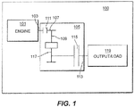
- FIG. 1 an illustrative view of an embodiment of a system in accordance with the disclosure is shown in Fig. 1 and is designated generally by reference character 100.
- FIGs. 2-4 Other embodiments and/or aspects of this disclosure are shown in Figs. 2-4 . Certain embodiments described herein can be used to reduce size and weight of aircraft systems and transmissions used therein.
- an engine system 100 can include an engine 101 having an engine shaft 103 and a transmission 105 that can include an input shaft 107 connected to the engine shaft 103 to rotate with the engine shaft 107 (e.g., at a same speed or a fixed gear ratio for example).
- the transmission 105 can include one or more rotating gears 109 configured to rotate relative to the input shaft 107.
- the transmission 105 can include a synchromesh 111 configured to selectively engage each of the one or more rotating gears 109 to the input shaft 107.
- the transmission 105 can include a second shaft 113 comprising a clutch 115 configured to selectively engage the one or more rotating gears 109 to the second shaft 113 to cause the second shaft 113 to rotate with the one or more rotating gears 109 (e.g., by driving a second shaft gear 117 attached to a housing of the clutch 115).
- the clutch 115 can be larger than the synchromesh 111.
- the clutch 115 can be configured to operate in a tighter range of torque values than the synchromesh 111.
- the clutch 115 can include any suitable clutch mechanism (e.g., a friction clutch having a bell housing assembly, e.g., as shown in Figs. 3 and 4 ).
- the clutch 115 can include a second shaft gear 117 disposed thereon and meshed with a rotating gear 109 of the one or more rotating gears 109.
- the second shaft 113 can be an output shaft configured to connect to one or more aircraft accessories (e.g., any suitable load 119).
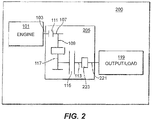
- the second shaft 113 can be connected to an output shaft 221 via a gear pair 223, for example.
- Any other suitable number of shafts (e.g., a third shaft) and any other suitable number of synchronizers and/or large clutches and/or gears is contemplated herein.
- Figs. 3 and 4 show an embodiment of a transmission 300 (e.g., a 4 stage transmission) having an input shaft 307 connectable to an engine shaft 303, a second shaft 313a, a third shaft 313b, a plurality of synchromeshes 311, a plurality of clutches 315, and each shaft 313a, 313b connected to an output shaft 321 via a gear ratio 323.
- the components of transmission 300 can include any suitable embodiment thereof disclosed herein, e.g., as described above. Any other suitable components are contemplated herein.
- the engine 101 can be an aircraft turbomachine. Any other suitable engine is contemplated herein.
- a turbomachine transmission can include and suitable embodiment of a transmission as disclosed herein (e.g., as described above). Any other suitable components for the transmission are contemplated herein.
- an aircraft system can include an engine having an engine shaft and a transmission as disclosed herein (e.g., as described above).
- the aircraft system can include an output shaft connected to the second shaft, and a load connected to the second shaft. Any other suitable components are contemplated herein.
- a typical automotive transmission has the main/large clutch close to the engine. This is done because the torque band there is the tightest. Then power flows to synchromesh and gear ratios to the output. In certain turbomachine systems (e.g., for a low speed spool generator), this is the opposite and the greatest range of torque is at the engine. Therefore it may be best to place the clutch on the opposite side of the gear ratios than the turbomachine.
- Embodiments include the large clutch on the other side of the synchromesh and switched gear ratios. Therefore, the large clutch is closer to a constant torque. Embodiments can drastically reduce the size of the clutch, and in turn reduces the size of the transmission.
- any numerical values disclosed herein can be exact values or can be values within a range. Further, any terms of approximation (e.g., “about”, “approximately”, “around”) used in this disclosure can mean the stated value within a range. For example, in certain embodiments, the range can be within (plus or minus) 20%, or within 10%, or within 5%, or within 2%, or within any other suitable percentage or number as appreciated by those having ordinary skill in the art (e.g., for known tolerance limits or error ranges).
Landscapes
- Engineering & Computer Science (AREA)
- General Engineering & Computer Science (AREA)
- Chemical & Material Sciences (AREA)
- Combustion & Propulsion (AREA)
- Mechanical Engineering (AREA)
- Structure Of Transmissions (AREA)
Abstract
Description
- This disclosure relates to transmission systems, e.g., for aircraft low speed spool turbomachines.
- Moving turbomachine accessories to be driven by the low speed spool requires a speed increasing transmission to take a large speed ratio and turn it into a tighter speed ratio band. One method of doing this is the use of a shifting transmission consisting of clutches that selectively engage different gear ratios. Since this load device can be a generator, it can represent a constant power load demand. This is different than what a traditional transmission encounters in use which is usually constant torque.
- Such conventional methods and systems have generally been considered satisfactory for their intended purpose. However, there is still a need in the art for improved transmission systems. The present disclosure provides a solution for this need.
- An engine system can include an engine having an engine shaft and a transmission that can include an input shaft connected to the engine shaft to rotate with the engine shaft, one or more rotating gears configured to rotate relative to the input shaft, and a synchromesh configured to selectively engage each of the one or more rotating gears to the input shaft. Transmission can include a second shaft comprising a clutch configured to selectively engage the one or more rotating gears to the second shaft to cause the second shaft to rotate with the one or more rotating gears.
- The clutch can be larger than the synchromesh. The clutch can be configured to operate in a tighter range of torque values than the synchromesh. The clutch can include any suitable clutch mechanism (e.g., a friction clutch having a bell housing assembly). The clutch can include a second shaft gear disposed thereon and meshed with a rotating gear of the one or more rotating gears.
- The second shaft can be an output shaft configured to connect to one or more aircraft accessories. In certain embodiments, the second shaft can be connected to an output shaft via a gear pair, for example. Any other suitable number of shafts (e.g., a third shaft) and any other suitable number of synchronizers and/or large clutches is contemplated herein.
- In certain embodiments, the engine can be an aircraft turbomachine. Any other suitable engine is contemplated herein.
- In accordance with at least one aspect of this disclosure, a turbomachine transmission can include and suitable embodiment of a transmission as disclosed herein (e.g., as described above). Any other suitable components for the transmission are contemplated herein.
- In accordance with at least one aspect of this disclosure, an aircraft system can include an engine having an engine shaft and a transmission as disclosed herein (e.g., as described above). The aircraft system can include an output shaft connected to the second shaft, and a load connected to the second shaft. Any other suitable components are contemplated herein.
- These and other features of the embodiments of the subject disclosure will become more readily apparent to those skilled in the art from the following detailed description taken in conjunction with the drawings.
- So that those skilled in the art to which the subject disclosure appertains will readily understand how to make and use the devices and methods of the subject disclosure without undue experimentation, embodiments thereof will be described in detail herein below with reference to certain figures, wherein:
-
Fig. 1 is a schematic view of an embodiment of a system in accordance with this disclosure; -
Fig. 2 is a schematic view of an embodiment of a system in accordance with this disclosure; -
Fig. 3 is a perspective view of an embodiment of a transmission in accordance with this disclosure; and -
Fig. 4 is a cross-sectional view of the embodiment ofFig. 3 , shown sectioned through the input shaft and the output shaft. - Reference will now be made to the drawings wherein like reference numerals identify similar structural features or aspects of the subject disclosure. For purposes of explanation and illustration, and not limitation, an illustrative view of an embodiment of a system in accordance with the disclosure is shown in
Fig. 1 and is designated generally byreference character 100. Other embodiments and/or aspects of this disclosure are shown inFigs. 2-4 . Certain embodiments described herein can be used to reduce size and weight of aircraft systems and transmissions used therein. - Referring to
Fig. 1 , anengine system 100 can include anengine 101 having anengine shaft 103 and atransmission 105 that can include aninput shaft 107 connected to theengine shaft 103 to rotate with the engine shaft 107 (e.g., at a same speed or a fixed gear ratio for example). Thetransmission 105 can include one or morerotating gears 109 configured to rotate relative to theinput shaft 107. Thetransmission 105 can include asynchromesh 111 configured to selectively engage each of the one or morerotating gears 109 to theinput shaft 107. Thetransmission 105 can include asecond shaft 113 comprising aclutch 115 configured to selectively engage the one or morerotating gears 109 to thesecond shaft 113 to cause thesecond shaft 113 to rotate with the one or more rotating gears 109 (e.g., by driving asecond shaft gear 117 attached to a housing of the clutch 115). - The
clutch 115 can be larger than thesynchromesh 111. Theclutch 115 can be configured to operate in a tighter range of torque values than thesynchromesh 111. Theclutch 115 can include any suitable clutch mechanism (e.g., a friction clutch having a bell housing assembly, e.g., as shown inFigs. 3 and4 ). Theclutch 115 can include asecond shaft gear 117 disposed thereon and meshed with a rotatinggear 109 of the one or morerotating gears 109. - The
second shaft 113 can be an output shaft configured to connect to one or more aircraft accessories (e.g., any suitable load 119). In certain embodiments, as shown inFig. 2 , thesecond shaft 113 can be connected to anoutput shaft 221 via agear pair 223, for example. Any other suitable number of shafts (e.g., a third shaft) and any other suitable number of synchronizers and/or large clutches and/or gears is contemplated herein. - For example,
Figs. 3 and4 show an embodiment of a transmission 300 (e.g., a 4 stage transmission) having aninput shaft 307 connectable to anengine shaft 303, asecond shaft 313a, athird shaft 313b, a plurality ofsynchromeshes 311, a plurality ofclutches 315, and eachshaft output shaft 321 via agear ratio 323. The components oftransmission 300 can include any suitable embodiment thereof disclosed herein, e.g., as described above. Any other suitable components are contemplated herein. - In certain embodiments, the
engine 101 can be an aircraft turbomachine. Any other suitable engine is contemplated herein. - In accordance with at least one aspect of this disclosure, a turbomachine transmission can include and suitable embodiment of a transmission as disclosed herein (e.g., as described above). Any other suitable components for the transmission are contemplated herein.
- In accordance with at least one aspect of this disclosure, an aircraft system can include an engine having an engine shaft and a transmission as disclosed herein (e.g., as described above). The aircraft system can include an output shaft connected to the second shaft, and a load connected to the second shaft. Any other suitable components are contemplated herein.
- A typical automotive transmission has the main/large clutch close to the engine. This is done because the torque band there is the tightest. Then power flows to synchromesh and gear ratios to the output. In certain turbomachine systems (e.g., for a low speed spool generator), this is the opposite and the greatest range of torque is at the engine. Therefore it may be best to place the clutch on the opposite side of the gear ratios than the turbomachine. Embodiments include the large clutch on the other side of the synchromesh and switched gear ratios. Therefore, the large clutch is closer to a constant torque. Embodiments can drastically reduce the size of the clutch, and in turn reduces the size of the transmission.
- Those having ordinary skill in the art understand that any numerical values disclosed herein can be exact values or can be values within a range. Further, any terms of approximation (e.g., "about", "approximately", "around") used in this disclosure can mean the stated value within a range. For example, in certain embodiments, the range can be within (plus or minus) 20%, or within 10%, or within 5%, or within 2%, or within any other suitable percentage or number as appreciated by those having ordinary skill in the art (e.g., for known tolerance limits or error ranges).
- Any suitable combination(s) of any disclosed embodiments and/or any suitable portion(s) thereof are contemplated herein as appreciated by those having ordinary skill in the art.
- The embodiments of the present disclosure, as described above and shown in the drawings, provide for improvement in the art to which they pertain. While the subject disclosure includes reference to certain embodiments, those skilled in the art will readily appreciate that changes and/or modifications may be made thereto without departing from the spirit and scope of the subject disclosure.
Claims (14)
- An engine system (100), comprising:an engine (101) having an engine shaft (103); anda transmission (105) comprising:an input shaft (107) connected to the engine shaft to rotate with the engine shaft (103);one or more rotating gears configured to rotate relative to the input shaft (107);a synchromesh (111) configured to selectively engage each of the one or more rotating gears (109) to the input shaft (107);a second shaft (113) comprising a clutch (115) configured to selectively engage the one or more rotating gears (109) to the second shaft to cause the second shaft (113) to rotate with the one or more rotating gears (109).
- The system of claim 1, wherein the clutch (115) is larger than the synchromesh (111).
- The system of any preceding claim, wherein the clutch (115) is configured to operate in a tighter range of torque values than the synchromesh (111).
- The system of any preceding claim, wherein the clutch (115) includes a second shaft gear (117) disposed thereon and meshed with a rotating gear (109) of the one or more rotating gears (109).
- The system of any preceding claim, wherein the second shaft (113) is an output shaft configured to connect to one or more aircraft accessories.
- The system of any preceding claim, wherein the second shaft (113) is connected to an output shaft via a gear pair.
- The system of any preceding claim, wherein the engine is an aircraft turbomachine.
- An aircraft system, comprising the engine system of any preceding claim, and further comprising:an output shaft connected to the second shaft (113); anda load connected to the second shaft (113).
- A turbomachine transmission, comprising:an input shaft (107) configured to connect to the engine shaft to rotate with the engine shaft (103);one or more rotating gears (109) configured to rotate relative to the input shaft (107);a synchromesh (111) configured to selectively engage each of the one or more rotating gears to the input shaft;a second shaft (113) comprising a clutch (115) configured to selectively engage the one or more rotating gears (109) to the second shaft (113) to cause the second shaft to rotate with the one or more rotating gears (109).
- The transmission of claim 9, wherein the clutch (115) is larger than the synchromesh (111).
- The transmission of claim 9 or 10, wherein the clutch (115) is configured to operate in a tighter range of torque values than the synchromesh (111).
- The transmission of any of claims 9 to 11, wherein the clutch (115) includes a second shaft gear (117) disposed thereon and meshed with a rotating gear (109) of the one or more rotating gears (109).
- The transmission of any of claims 9 to 12, wherein the second shaft (113) is an output shaft configured to connect to one or more aircraft accessories.
- The transmission of any of claims 9 to 13, wherein the second shaft (113) is connected to an output shaft via a gear pair.
Applications Claiming Priority (1)
| Application Number | Priority Date | Filing Date | Title |
|---|---|---|---|
| US16/388,548 US11834998B2 (en) | 2019-04-18 | 2019-04-18 | Transmission systems having clutch at output side |
Publications (1)
| Publication Number | Publication Date |
|---|---|
| EP3726030A1 true EP3726030A1 (en) | 2020-10-21 |
Family
ID=68840852
Family Applications (1)
| Application Number | Title | Priority Date | Filing Date |
|---|---|---|---|
| EP19210048.5A Pending EP3726030A1 (en) | 2019-04-18 | 2019-11-19 | Transmission systems having clutch at output side |
Country Status (2)
| Country | Link |
|---|---|
| US (1) | US11834998B2 (en) |
| EP (1) | EP3726030A1 (en) |
Families Citing this family (1)
| Publication number | Priority date | Publication date | Assignee | Title |
|---|---|---|---|---|
| US12486794B2 (en) * | 2023-03-02 | 2025-12-02 | Ferrari S.P.A. | Propulsion assembly for a motor vehicle |
Citations (6)
| Publication number | Priority date | Publication date | Assignee | Title |
|---|---|---|---|---|
| US3441116A (en) * | 1966-12-13 | 1969-04-29 | United Aircraft Corp | Electrically operated clutch mechanism |
| US6546830B2 (en) * | 2000-09-14 | 2003-04-15 | Fuji Jukogyo Kabushiki Kaisha | Transmission device of four-wheel drive vehicle |
| US20060276291A1 (en) * | 2005-06-03 | 2006-12-07 | Fabry Mark D | Hydromechanical transmission |
| CN2924171Y (en) * | 2006-05-31 | 2007-07-18 | 华南理工大学 | Dual-clutch type automatic transmission for preventing two-gear from being locked |
| US20080047376A1 (en) * | 2006-08-24 | 2008-02-28 | Gideon Venter | Arrangement for power take-off on a two-shaft engine |
| US20160017958A1 (en) * | 2014-07-18 | 2016-01-21 | Uvic Industry Partnerships Inc. | Electric drive system with a novel dual-clutch transmission |
Family Cites Families (11)
| Publication number | Priority date | Publication date | Assignee | Title |
|---|---|---|---|---|
| JP3660528B2 (en) * | 1999-06-07 | 2005-06-15 | 本田技研工業株式会社 | Parallel shaft type transmission |
| US6647817B2 (en) * | 2000-02-14 | 2003-11-18 | Fuji Jukogyo Kabushiki Kaisha | Automatic transmission |
| JP4082926B2 (en) | 2002-05-07 | 2008-04-30 | 本田技研工業株式会社 | Automatic transmission |
| US7942079B2 (en) | 2007-02-16 | 2011-05-17 | Hamilton Sundstrand Corporation | Multi-speed gearbox for low spool driven auxiliary component |
| DE102009006647B4 (en) | 2008-02-04 | 2019-01-31 | Schaeffler Technologies AG & Co. KG | Dual clutch assembly |
| US8840505B2 (en) | 2011-02-24 | 2014-09-23 | Ford Global Technologies, Llc | Hydraulic controls for an automatic transmission |
| US9347373B2 (en) | 2013-12-19 | 2016-05-24 | Pratt & Whitney Canada Corp. | Gas turbine engine with transmission |
| US10167948B2 (en) | 2016-03-17 | 2019-01-01 | GM Global Technology Operations LLC | Hydraulic control system for an automatic transmission |
| KR101878044B1 (en) * | 2016-07-22 | 2018-07-16 | 현대자동차주식회사 | Transmission for hybrid vehicle |
| US20180045119A1 (en) | 2016-08-09 | 2018-02-15 | United Technologies Corporation | Geared turbofan with low spool power extraction |
| US10495186B2 (en) | 2017-01-20 | 2019-12-03 | Hamilton Sundstrand Corporation | Low speed spool generator transmission |
-
2019
- 2019-04-18 US US16/388,548 patent/US11834998B2/en active Active
- 2019-11-19 EP EP19210048.5A patent/EP3726030A1/en active Pending
Patent Citations (6)
| Publication number | Priority date | Publication date | Assignee | Title |
|---|---|---|---|---|
| US3441116A (en) * | 1966-12-13 | 1969-04-29 | United Aircraft Corp | Electrically operated clutch mechanism |
| US6546830B2 (en) * | 2000-09-14 | 2003-04-15 | Fuji Jukogyo Kabushiki Kaisha | Transmission device of four-wheel drive vehicle |
| US20060276291A1 (en) * | 2005-06-03 | 2006-12-07 | Fabry Mark D | Hydromechanical transmission |
| CN2924171Y (en) * | 2006-05-31 | 2007-07-18 | 华南理工大学 | Dual-clutch type automatic transmission for preventing two-gear from being locked |
| US20080047376A1 (en) * | 2006-08-24 | 2008-02-28 | Gideon Venter | Arrangement for power take-off on a two-shaft engine |
| US20160017958A1 (en) * | 2014-07-18 | 2016-01-21 | Uvic Industry Partnerships Inc. | Electric drive system with a novel dual-clutch transmission |
Also Published As
| Publication number | Publication date |
|---|---|
| US11834998B2 (en) | 2023-12-05 |
| US20200332720A1 (en) | 2020-10-22 |
Similar Documents
| Publication | Publication Date | Title |
|---|---|---|
| EP3351825B1 (en) | Low speed spool generator transmission | |
| US10024394B2 (en) | Multi-speed transmission | |
| US9518638B2 (en) | Multi-speed transmission | |
| US9541168B2 (en) | Multi-speed transmission | |
| US9631707B2 (en) | Multi-speed transmission | |
| US9512905B2 (en) | Multi-speed transmission | |
| US10634222B2 (en) | Multi-speed transmission | |
| US8162118B2 (en) | Lash control in a transmission coupler | |
| US9958032B2 (en) | Transmission for vehicle | |
| US10393235B2 (en) | Multi-speed transmission | |
| US11226026B2 (en) | Multispeed transmission | |
| EP0644355A1 (en) | Power transmission | |
| US8474343B2 (en) | Transmission having a low launch gear | |
| US11834998B2 (en) | Transmission systems having clutch at output side | |
| US20010042416A1 (en) | Manual transmission | |
| US9964194B2 (en) | Power split transmission | |
| US11287016B2 (en) | Multi-gear transmission layout | |
| US8474342B2 (en) | Transmission having a low launch gear | |
| US9869369B2 (en) | Transmission for vehicle | |
| US9897164B2 (en) | Transmission for vehicle | |
| US10975935B2 (en) | Dual clutch-type transmission | |
| EP3726085A1 (en) | Clutch systems for transmissions | |
| US20180363736A1 (en) | Transmission for vehicles | |
| US9470293B1 (en) | Multi-speed transmission | |
| US20160273619A1 (en) | Manual transmission |
Legal Events
| Date | Code | Title | Description |
|---|---|---|---|
| PUAI | Public reference made under article 153(3) epc to a published international application that has entered the european phase |
Free format text: ORIGINAL CODE: 0009012 |
|
| STAA | Information on the status of an ep patent application or granted ep patent |
Free format text: STATUS: THE APPLICATION HAS BEEN PUBLISHED |
|
| AK | Designated contracting states |
Kind code of ref document: A1 Designated state(s): AL AT BE BG CH CY CZ DE DK EE ES FI FR GB GR HR HU IE IS IT LI LT LU LV MC MK MT NL NO PL PT RO RS SE SI SK SM TR |
|
| STAA | Information on the status of an ep patent application or granted ep patent |
Free format text: STATUS: REQUEST FOR EXAMINATION WAS MADE |
|
| 17P | Request for examination filed |
Effective date: 20210421 |
|
| RBV | Designated contracting states (corrected) |
Designated state(s): AL AT BE BG CH CY CZ DE DK EE ES FI FR GB GR HR HU IE IS IT LI LT LU LV MC MK MT NL NO PL PT RO RS SE SI SK SM TR |
|
| STAA | Information on the status of an ep patent application or granted ep patent |
Free format text: STATUS: EXAMINATION IS IN PROGRESS |
|
| 17Q | First examination report despatched |
Effective date: 20220920 |