EP3726018B1 - Exhaust gas treatment device for an exhaust system of an internal combustion engine - Google Patents
Exhaust gas treatment device for an exhaust system of an internal combustion engine Download PDFInfo
- Publication number
- EP3726018B1 EP3726018B1 EP20170091.1A EP20170091A EP3726018B1 EP 3726018 B1 EP3726018 B1 EP 3726018B1 EP 20170091 A EP20170091 A EP 20170091A EP 3726018 B1 EP3726018 B1 EP 3726018B1
- Authority
- EP
- European Patent Office
- Prior art keywords
- base wall
- treatment device
- tubular
- side wall
- inlet opening
- Prior art date
- Legal status (The legal status is an assumption and is not a legal conclusion. Google has not performed a legal analysis and makes no representation as to the accuracy of the status listed.)
- Not-in-force
Links
Images




Classifications
-
- F—MECHANICAL ENGINEERING; LIGHTING; HEATING; WEAPONS; BLASTING
- F01—MACHINES OR ENGINES IN GENERAL; ENGINE PLANTS IN GENERAL; STEAM ENGINES
- F01N—GAS-FLOW SILENCERS OR EXHAUST APPARATUS FOR MACHINES OR ENGINES IN GENERAL; GAS-FLOW SILENCERS OR EXHAUST APPARATUS FOR INTERNAL-COMBUSTION ENGINES
- F01N3/00—Exhaust or silencing apparatus having means for purifying, rendering innocuous, or otherwise treating exhaust
- F01N3/08—Exhaust or silencing apparatus having means for purifying, rendering innocuous, or otherwise treating exhaust for rendering innocuous
- F01N3/10—Exhaust or silencing apparatus having means for purifying, rendering innocuous, or otherwise treating exhaust for rendering innocuous by thermal or catalytic conversion of noxious components of exhaust
- F01N3/24—Exhaust or silencing apparatus having means for purifying, rendering innocuous, or otherwise treating exhaust for rendering innocuous by thermal or catalytic conversion of noxious components of exhaust characterised by constructional aspects of converting apparatus
- F01N3/28—Construction of catalytic reactors
-
- F—MECHANICAL ENGINEERING; LIGHTING; HEATING; WEAPONS; BLASTING
- F01—MACHINES OR ENGINES IN GENERAL; ENGINE PLANTS IN GENERAL; STEAM ENGINES
- F01N—GAS-FLOW SILENCERS OR EXHAUST APPARATUS FOR MACHINES OR ENGINES IN GENERAL; GAS-FLOW SILENCERS OR EXHAUST APPARATUS FOR INTERNAL-COMBUSTION ENGINES
- F01N3/00—Exhaust or silencing apparatus having means for purifying, rendering innocuous, or otherwise treating exhaust
- F01N3/08—Exhaust or silencing apparatus having means for purifying, rendering innocuous, or otherwise treating exhaust for rendering innocuous
- F01N3/10—Exhaust or silencing apparatus having means for purifying, rendering innocuous, or otherwise treating exhaust for rendering innocuous by thermal or catalytic conversion of noxious components of exhaust
- F01N3/18—Exhaust or silencing apparatus having means for purifying, rendering innocuous, or otherwise treating exhaust for rendering innocuous by thermal or catalytic conversion of noxious components of exhaust characterised by methods of operation; Control
- F01N3/20—Exhaust or silencing apparatus having means for purifying, rendering innocuous, or otherwise treating exhaust for rendering innocuous by thermal or catalytic conversion of noxious components of exhaust characterised by methods of operation; Control specially adapted for catalytic conversion
- F01N3/206—Adding periodically or continuously substances to exhaust gases for promoting purification, e.g. catalytic material in liquid form, NOx reducing agents
- F01N3/2066—Selective catalytic reduction [SCR]
-
- B—PERFORMING OPERATIONS; TRANSPORTING
- B01—PHYSICAL OR CHEMICAL PROCESSES OR APPARATUS IN GENERAL
- B01F—MIXING, e.g. DISSOLVING, EMULSIFYING OR DISPERSING
- B01F23/00—Mixing according to the phases to be mixed, e.g. dispersing or emulsifying
- B01F23/20—Mixing gases with liquids
- B01F23/21—Mixing gases with liquids by introducing liquids into gaseous media
- B01F23/213—Mixing gases with liquids by introducing liquids into gaseous media by spraying or atomising of the liquids
- B01F23/2132—Mixing gases with liquids by introducing liquids into gaseous media by spraying or atomising of the liquids using nozzles
-
- B—PERFORMING OPERATIONS; TRANSPORTING
- B01—PHYSICAL OR CHEMICAL PROCESSES OR APPARATUS IN GENERAL
- B01F—MIXING, e.g. DISSOLVING, EMULSIFYING OR DISPERSING
- B01F25/00—Flow mixers; Mixers for falling materials, e.g. solid particles
- B01F25/30—Injector mixers
- B01F25/31—Injector mixers in conduits or tubes through which the main component flows
- B01F25/314—Injector mixers in conduits or tubes through which the main component flows wherein additional components are introduced at the circumference of the conduit
- B01F25/3141—Injector mixers in conduits or tubes through which the main component flows wherein additional components are introduced at the circumference of the conduit with additional mixing means other than injector mixers
-
- B—PERFORMING OPERATIONS; TRANSPORTING
- B01—PHYSICAL OR CHEMICAL PROCESSES OR APPARATUS IN GENERAL
- B01F—MIXING, e.g. DISSOLVING, EMULSIFYING OR DISPERSING
- B01F25/00—Flow mixers; Mixers for falling materials, e.g. solid particles
- B01F25/40—Static mixers
- B01F25/42—Static mixers in which the mixing is affected by moving the components jointly in changing directions, e.g. in tubes provided with baffles or obstructions
- B01F25/421—Static mixers in which the mixing is affected by moving the components jointly in changing directions, e.g. in tubes provided with baffles or obstructions by moving the components in a convoluted or labyrinthine path
- B01F25/423—Static mixers in which the mixing is affected by moving the components jointly in changing directions, e.g. in tubes provided with baffles or obstructions by moving the components in a convoluted or labyrinthine path by means of elements placed in the receptacle for moving or guiding the components
- B01F25/4231—Static mixers in which the mixing is affected by moving the components jointly in changing directions, e.g. in tubes provided with baffles or obstructions by moving the components in a convoluted or labyrinthine path by means of elements placed in the receptacle for moving or guiding the components using baffles
-
- F—MECHANICAL ENGINEERING; LIGHTING; HEATING; WEAPONS; BLASTING
- F01—MACHINES OR ENGINES IN GENERAL; ENGINE PLANTS IN GENERAL; STEAM ENGINES
- F01N—GAS-FLOW SILENCERS OR EXHAUST APPARATUS FOR MACHINES OR ENGINES IN GENERAL; GAS-FLOW SILENCERS OR EXHAUST APPARATUS FOR INTERNAL-COMBUSTION ENGINES
- F01N13/00—Exhaust or silencing apparatus characterised by constructional features
- F01N13/08—Other arrangements or adaptations of exhaust conduits
- F01N13/082—Other arrangements or adaptations of exhaust conduits of tailpipe, e.g. with means for mixing air with exhaust for exhaust cooling, dilution or evacuation
-
- F—MECHANICAL ENGINEERING; LIGHTING; HEATING; WEAPONS; BLASTING
- F01—MACHINES OR ENGINES IN GENERAL; ENGINE PLANTS IN GENERAL; STEAM ENGINES
- F01N—GAS-FLOW SILENCERS OR EXHAUST APPARATUS FOR MACHINES OR ENGINES IN GENERAL; GAS-FLOW SILENCERS OR EXHAUST APPARATUS FOR INTERNAL-COMBUSTION ENGINES
- F01N3/00—Exhaust or silencing apparatus having means for purifying, rendering innocuous, or otherwise treating exhaust
- F01N3/08—Exhaust or silencing apparatus having means for purifying, rendering innocuous, or otherwise treating exhaust for rendering innocuous
- F01N3/10—Exhaust or silencing apparatus having means for purifying, rendering innocuous, or otherwise treating exhaust for rendering innocuous by thermal or catalytic conversion of noxious components of exhaust
- F01N3/24—Exhaust or silencing apparatus having means for purifying, rendering innocuous, or otherwise treating exhaust for rendering innocuous by thermal or catalytic conversion of noxious components of exhaust characterised by constructional aspects of converting apparatus
- F01N3/28—Construction of catalytic reactors
- F01N3/2892—Exhaust flow directors or the like, e.g. upstream of catalytic device
-
- B—PERFORMING OPERATIONS; TRANSPORTING
- B01—PHYSICAL OR CHEMICAL PROCESSES OR APPARATUS IN GENERAL
- B01D—SEPARATION
- B01D2251/00—Reactants
- B01D2251/20—Reductants
- B01D2251/206—Ammonium compounds
- B01D2251/2067—Urea
-
- F—MECHANICAL ENGINEERING; LIGHTING; HEATING; WEAPONS; BLASTING
- F01—MACHINES OR ENGINES IN GENERAL; ENGINE PLANTS IN GENERAL; STEAM ENGINES
- F01N—GAS-FLOW SILENCERS OR EXHAUST APPARATUS FOR MACHINES OR ENGINES IN GENERAL; GAS-FLOW SILENCERS OR EXHAUST APPARATUS FOR INTERNAL-COMBUSTION ENGINES
- F01N2240/00—Combination or association of two or more different exhaust treating devices, or of at least one such device with an auxiliary device, not covered by indexing codes F01N2230/00 or F01N2250/00, one of the devices being
- F01N2240/20—Combination or association of two or more different exhaust treating devices, or of at least one such device with an auxiliary device, not covered by indexing codes F01N2230/00 or F01N2250/00, one of the devices being a flow director or deflector
-
- F—MECHANICAL ENGINEERING; LIGHTING; HEATING; WEAPONS; BLASTING
- F01—MACHINES OR ENGINES IN GENERAL; ENGINE PLANTS IN GENERAL; STEAM ENGINES
- F01N—GAS-FLOW SILENCERS OR EXHAUST APPARATUS FOR MACHINES OR ENGINES IN GENERAL; GAS-FLOW SILENCERS OR EXHAUST APPARATUS FOR INTERNAL-COMBUSTION ENGINES
- F01N2610/00—Adding substances to exhaust gases
- F01N2610/02—Adding substances to exhaust gases the substance being ammonia or urea
-
- F—MECHANICAL ENGINEERING; LIGHTING; HEATING; WEAPONS; BLASTING
- F01—MACHINES OR ENGINES IN GENERAL; ENGINE PLANTS IN GENERAL; STEAM ENGINES
- F01N—GAS-FLOW SILENCERS OR EXHAUST APPARATUS FOR MACHINES OR ENGINES IN GENERAL; GAS-FLOW SILENCERS OR EXHAUST APPARATUS FOR INTERNAL-COMBUSTION ENGINES
- F01N2610/00—Adding substances to exhaust gases
- F01N2610/08—Adding substances to exhaust gases with prior mixing of the substances with a gas, e.g. air
-
- F—MECHANICAL ENGINEERING; LIGHTING; HEATING; WEAPONS; BLASTING
- F01—MACHINES OR ENGINES IN GENERAL; ENGINE PLANTS IN GENERAL; STEAM ENGINES
- F01N—GAS-FLOW SILENCERS OR EXHAUST APPARATUS FOR MACHINES OR ENGINES IN GENERAL; GAS-FLOW SILENCERS OR EXHAUST APPARATUS FOR INTERNAL-COMBUSTION ENGINES
- F01N2610/00—Adding substances to exhaust gases
- F01N2610/14—Arrangements for the supply of substances, e.g. conduits
-
- Y—GENERAL TAGGING OF NEW TECHNOLOGICAL DEVELOPMENTS; GENERAL TAGGING OF CROSS-SECTIONAL TECHNOLOGIES SPANNING OVER SEVERAL SECTIONS OF THE IPC; TECHNICAL SUBJECTS COVERED BY FORMER USPC CROSS-REFERENCE ART COLLECTIONS [XRACs] AND DIGESTS
- Y02—TECHNOLOGIES OR APPLICATIONS FOR MITIGATION OR ADAPTATION AGAINST CLIMATE CHANGE
- Y02T—CLIMATE CHANGE MITIGATION TECHNOLOGIES RELATED TO TRANSPORTATION
- Y02T10/00—Road transport of goods or passengers
- Y02T10/10—Internal combustion engine [ICE] based vehicles
- Y02T10/12—Improving ICE efficiencies
Definitions
- the invention relates to an exhaust gas treatment device for an exhaust system of an internal combustion engine.
- the concentration of ammonia on the surface of the monolith of the SCR catalytic converter needs to be as homogeneous as possible. Furthermore, a problem linked to the injection of a water solution of urea into the exhaust system is due to the fact that on the inner walls of the exhaust system there can be hardly removable solid deposits both of urea and of isocyanic acid (NHCO), which is a possible derivative of the decomposition of urea.
- NHCO isocyanic acid
- Patent application WO2018001789A1 discloses an exhaust gas treatment device, which is provided with a injector for a reducing additive in the area of a static mixer (namely, without of moving parts).
- Patent US9346017B2 discloses an exhaust line of a motor vehicle comprising an upstream monolith and a downstream monolith for the treatment of the exhaust gases; between the two monoliths there are an injector for a water solution of urea and a mixing body, which forces the exhaust gases to follow a circular path.
- known mixers of the type described above suffer from the drawback of not having an ideal balance between the opposing needs of effectiveness (namely, of ensuring a proper mixing of the exhaust gases) and of efficiency (namely, of limiting load losses in the exhaust gases).
- known mixers of the type described above wither have a low effectiveness (namely, do to ensure a proper mixing of the exhaust gases) or have a low efficiency (namely, cause high load losses in the exhaust gases) .
- the object of the invention is to provide an exhaust gas treatment device for an exhaust system of an internal combustion engine, said treatment device not suffering from the drawbacks described above and, in particular, being easy and economic to be manufactured.
- an exhaust gas treatment device for an exhaust system of an internal combustion engine according to the appended claims.
- number 1 indicates, as a whole, an exhaust gas treatment device for an exhaust system of an internal combustion engine operating according to a " Diesel " cycle (i.e. powered by Diesel fuel or the like).
- the exhaust gas treatment device 1 comprises a tubular duct 2, which has a central longitudinal axis 3 and has a cylindrical shape (namely, has a circular cross section with a constant diameter).
- the tubular duct 2 is delimited by a tubular side wall 4, which is made of sheet metal and has an exhaust gas inlet opening 5 (shown in figure 1 ), which is arranged in the area of a first base of the tubular duct 2, and an exhaust gas outlet opening 6 (shown in figure 2 ), which is opposite the inlet opening 5 and is arranged in the area of a second base of the tubular duct 2 (obviously, opposite the first base of the tubular duct 2); as a consequence, in use, the exhaust gases flow into the tubular duct 2 through the opening 5, flow through the tubular duct 2 and, then, flow out of the tubular duct 2 through the outlet opening 6.
- the tubular duct 2 further has an injection opening 7, which is obtained through the tubular side wall 4 between the inlet opening 5 and the outlet opening 6 and is designed to receive a reducing substance injector; in particular, around the opening 7 there is a tubular housing 8, which projects from the tubular side wall 4 and is configured to receive the injector.
- the injector is designed to inject into the tubular duct 2 a reducing additive and, in particular, a water solution of urea (i.e.
- the treatment device 1 comprises a mixing body 9 (a static mixing body, namely without moving parts), which is arranged inside the tubular duct 2, creates a forced path to be followed by the exhaust gases in order to flow from the inlet opening 5 to the outlet opening 6, and is hollow on the inside so that the exhaust gases can flow through it.
- the mixing body 9 has the function of generating turbulences in the exhaust gases present inside the tubular duct 2 so as to increase the efficiency of the following SCR catalytic converter, thus making the dispersion of ammonia in the exhaust gases more homogeneous.
- the mixing body 9 has a perforated base wall 10 with a circular shape, which faces the outlet opening 6 of the tubular duct 2 and completely engages (closes) the cross section of the tubular duct 2 (namely, the exhaust gases cannot flow past the base wall 10, except through the hole of the base wall 10 itself), a base wall 11 with a partially circular shape and without holes, which faces the inlet opening 5 of the tubular duct 2 and only partially engages (closes) the cross section of the tubular duct 2 (namely, the exhaust gases can flow past the base wall 11 by flowing beside the base wall 11 itself), and a tubular side wall 12, which joins the base wall 10 to the base wall 11 and has an inlet opening 13, which leads into the mixing body 9.
- the base walls 10 and 11 of the mixing body 9 and the tubular side wall 12 of the mixing body 9 are coaxial to the tubular duct 2 and, therefore, share with the tubular duct 2 the same central longitudinal symmetry axis 3.
- the base wall 10 of the mixing body 9 has one single outlet opening 14 with a circular shape, so that the exhaust gases flowing into the mixing body 9 through the inlet opening 13 can subsequently flow out of the mixing body 9 and quickly reach the outlet opening 6 of the tubular duct 2 flowing through the outlet opening 14.
- the exhaust gases flowing into the tubular duct 2 through the inlet opening 5 are necessarily forced to flow into the mixing body 9 through the inlet opening 13 and, then, to flow out of the mixing body 9 through the outlet opening 14 (since they can only flow out of the tubular body 2 by flowing through the inside of the mixing body 9).
- the inlet opening 13 of the mixing body 9 is arranged perpendicularly relative to the inlet opening 5 of the tubular body 2 and also relative to the outlet opening 14 of the mixing body 9 (and, hence, also relative to the outlet opening 6 of the tubular duct 2); this change in orientation between the inlet opening 5 of the tubular duct 2, the inlet opening 13 of the mixing body 9 and the outlet opening 14 of the mixing body 9 causes the exhaust gases to gain a (relevant) radial (circumferential) motion component, which is added to the main axial motion component.
- the exhaust gases also gain a circumferential motion component, which is added to the main axial motion component, also thanks to the fact that the base wall 11 of the mixing body 9 partially engages (closes) the cross section of the tubular body 2 in the area of the inlet opening 13 of the mixing body 9; as a consequence, the exhaust gases flowing into the tubular body 2 through the inlet opening 5 cannot directly reach the inlet opening 13 of the mixing body 9 by simply moving in an axial manner, but, first, they have to move around the tubular side wall 12 of the mixing body 9 for approximately 180° in order to reach the area behind the inlet opening 13 (not engaged by the base wall 11 of the mixing body 9), which can be reached by the exhaust gases by axially moving from the inlet opening 5 of the tubular duct 2 to the inlet opening 13 of the mixing body 9.
- the inlet opening 13 of the tubular side wall 12 of the mixing body 9 is arranged on the opposite side of the injection opening 7, so that the injection opening 7 faces a portion of the tubular side wall 12 without holes; furthermore, as already mentioned above, in the portion of the tubular side wall 12 of the mixing body 9 opposite the inlet opening 13, the exhaust gases have a turbulent motion (due to the radial and tangential motion components generated by the particular conformation of the mixing body 9), which enhances an ideal mixing of the reducing agent injected through the injection opening 7 with the exhaust gases.
- the tubular side wall 12 of the mixing body 9 has a conical shape, which is tapered from the base wall 10 to the base wall 11; namely, the tubular side wall 12 of the mixing body 9 has a maximum diameter in the area of the base wall 10 and has a minimum diameter in the area of the base wall 11.
- the tubular side wall 12 of the mixing body 9 has, as a whole, the shape of a truncated cone, which is tapered from the outlet opening 6 of the tubular duct 2 to the inlet opening 5 of the tubular duct 2.
- the conical shape of the tubular side wall 12 of the mixing body 9 determines a continuous change in the area of the cross section flown through by the exhaust gases flowing towards the outlet opening 6 of the tubular duct 2 and this continuous change determines an increase in the swirling motion of the exhaust gases (which positively affects the mixing of the reducing agent injected through the injection opening 7 with the exhaust gases).
- the base wall 10 of the mixing body 9 has an outer diameter which is greater than a diameter of the tubular side wall 12 in the area where it is joined to the base wall 10; as a consequence, the outlet opening 14 of the base wall 10 of the mixing body 9 also has a diameter which is smaller than the outer diameter of the base wall 10 and, hence, than a diameter of the outlet opening 6 of the tubular duct 2.
- the inlet opening 13 of the tubular side wall 12 of the mixing body 9 is symmetrically arranged between the base wall 10 and the base wall 11 of the mixing body 9; namely, the inlet opening 13 is at the same distance from the base wall 10 and from the base wall 11 of the mixing body 9.
- the inlet opening 13 of the tubular side wall 12 of the mixing body 9 develops for at least 120° (preferably 180°) around the central longitudinal axis 3 of the tubular side wall 12.
- the inlet opening 13 of the tubular side wall 12 of the mixing body 9 develops along at least 70% (preferably at least 85%) of an axial size of the tubular side wall 12.
- the base wall 10 of the mixing body 9 has an annular edge 15, which is perpendicular to the base wall 10, develops for 360° around the central longitudinal axis 3, and rests against and is fixed (welded) to an inner surface of the tubular side wall 4 of the tubular duct 2.
- the base wall 11 of the mixing body 9 also has an annular edge 16, which is perpendicular to the base wall 11, develops for 150-210° (preferably 180°) around the central longitudinal axis 3, and rests against and is fixed (welded) to an inner surface of the tubular side wall 4.
- the base wall 11 of the mixing body 9 has a central portion 17 with a circular shape, which closes the tubular side wall 12 (namely, has the same diameter as the tubular side wall 12) and is separate and relatively far from the inner surface of the tubular side wall 4, and a side portion 18 with the shape of a circular sector, which has a greater diameter than the central portion 17, only partially surrounds the central portion 17, and extends up to the inner surface of the tubular side wall 4.
- the edge 16 is arranged only in the area of the side portion 18 of the base wall 11 of the mixing body 9.
- the base wall 11 of the mixing body 9 is obtained by joining a first semicircle having the same diameter as the tubular side wall 4 of the mixing body 9 and a second semicircle having the same diameter as the tubular side wall 4 of the tubular duct 2; hence, the first semicircle of the base wall 11 is smaller, is relatively far from the inner surface of the tubular side wall 4, and is not provided with the edge 16, whereas the second semicircle is greater, extents up to the inner surface of the tubular side wall 4, and has the edge 16.
- Figures 5-8 show a different embodiment of the static mixing body 9, which is inserted inside the tubular duct 2 and creates a forced path to be followed by the exhaust gases in order to flow from the inlet opening 5 to the outlet opening 6.
- the mixing body 9 shown in figure 5-8 has the perforated base wall 10 with a circular shape, which faces the outlet opening 6 of the tubular duct 2 and completely engages (closes) the cross section of the tubular duct 2 (namely, the exhaust gases cannot flow past the base wall 10, except through the outlet opening 14 of the base wall 10 itself), the base wall 11 with a partially circular shape, which faces the inlet opening 5 of the tubular duct 2 and only partially engages (closes) the cross section of the tubular duct 2 (namely, the exhaust gases can flow past the base wall 11 by flowing beside the base wall 11 itself), and the tubular side wall 12, which joins the base wall 10 to the base wall 11 and has the inlet opening 13, which leads into the mixing body 9.
- the base wall 11 has a large plurality of small through holes 19 beside one another; in particular, there are different dozens of through holes 19 (approximately 80-100 through holes 19 in the embodiment shown in figures 5-8 ).
- Each through hole 19 has a diameter ranging from 1 to 3 mm, which means that the diameter of each through hole 19 is equal to a small fraction of a diameter of the tubular duct 2; for example, the diameter of each through hole 19 is equal to 1-3% of the diameter of the tubular duct 2.
- the base wall 11 of the mixing body 9 shown in the figures 5-8 is not provided with the through holes 19 (like the base wall 11 of the mixing body 9 shown in figures 1-4 ).
- the through holes 19 are arranged in the sole side portion 18 of the base wall 11 and, in particular, in an area opposite and far from the central portion 17 of the base wall 11 (namely, the central portion 17 of the base wall 11 is completely free from through holes).
- the through holes 19 allow only a modest fraction of the exhaust gases coming from the inlet opening 5 of the tubular body 2 to flow through the base wall 11 of the mixing body 9 moving in an axial manner, whereas the main part of the exhaust gases coming from the inlet opening 5 of the tubular body 2 is forced to flow around the tubular side wall 12 of the mixing body 9 for approximately 180° in order to reach the area behind the inlet opening 13 (not engaged by the base wall 11 of the mixing body 9), which can be reached by the exhaust gases by axially moving from the inlet opening 5 of the tubular duct 2 to the inlet opening 13 of the mixing body 9.
- the tubular side wall 12 of the mixing body 9 has a conical shape, which is tapered from the base wall 10 to the base wall 11; on the other hand, in the embodiment shown in figures 5-8 , the tubular side wall 12 of the mixing body 9 has a cylindrical shape (namely, with a constant diameter).
- the base wall 11 has two panels 20, which prolong the edge 16 (namely, build a local extension of the edge 16 without gaps) at the two opposite ends of the side wall 12 and are arranged radially (perpendicularly) relative to the side wall 12.
- the mixing body 9 comprises the two panels 20, which are arranged radially (perpendicularly) relative to the side wall 12, are perpendicular to the base wall 11, and extend from opposite ends of the side wall 12 up to the tubular duct 2.
- the two panels 20 have a smaller radial extension than the side wall 12 so as not to completely obstruct the path of the exhaust gases towards the inlet opening 13 of the mixing body 9.
- the function of the two panels 20 is that of making more winding the path of the exhaust gases that, from the inlet opening 5 of the tubular duct 2, have to reach the inlet opening 13 of the mixing body 9 in order to get to the outlet opening 6 of the tubular duct 2.
- the mixing body 9 consists of three distinct and separate pieces joined (welded) to one another: a first piece comprising the base wall 11, a second piece comprising the side wall 12, and a third piece comprising the base wall 10.
- the mixing body 9 is obtained by joining three initially distinct and separate pieces: a first piece comprising the base wall 11 and part of the side wall 12 having the inlet opening 13, a second piece comprising the remaining part of the side wall 12 without the inlet opening 13, and a third piece comprising the base wall 10; the first piece and the second piece making up the mixing body 9 interlock by means of the respective parts of the side wall 12, which are manufactured so as to be partially inserted into one another.
- the tubular duct 2 could also house an oxidation catalytic converter arranged upstream of the mixing body 9 (namely, the first one to be flown through by the exhaust gases) and/or a SCR (Selective Catalytic Reduction) catalytic converter for the after-treatment of NO x (NO and NO 2 ) molecules and arranged downstream of the mixing body 9 (namely, the last one to be flown through by the exhaust gases); the SCR catalytic converter could also integrate a particular filter.
- an oxidation catalytic converter arranged upstream of the mixing body 9 (namely, the first one to be flown through by the exhaust gases) and/or a SCR (Selective Catalytic Reduction) catalytic converter for the after-treatment of NO x (NO and NO 2 ) molecules and arranged downstream of the mixing body 9 (namely, the last one to be flown through by the exhaust gases); the SCR catalytic converter could also integrate a particular filter.
- the treatment device 1 described above has numerous advantages.
- the treatment device 1 described above offers an ideal balance between the opposing needs of effectiveness (namely, of ensuring a proper mixing of the exhaust gases) and of efficiency (namely, of causing limited load losses in the exhaust gases).
- the treatment device 1 described above has, at the same time, a high effectiveness (namely, ensures a proper mixing of the exhaust gases) and a high efficiency (namely, causes limited load losses in the exhaust gases).
- the treatment device 1 described above is particularly sturdy (hence, offers a long operating life and a very low risk of breaking), since it consists of a few parts.
- the treatment device 1 described above has particularly small sizes (especially axial sizes) and a modest overall weight.
- the treatment device 1 described above is simple and economic to be manufactured, since it consists of a few parts with a non-complicated shape and easy to be joined with standard annular welds.
Landscapes
- Chemical & Material Sciences (AREA)
- Engineering & Computer Science (AREA)
- Chemical Kinetics & Catalysis (AREA)
- Combustion & Propulsion (AREA)
- Mechanical Engineering (AREA)
- General Engineering & Computer Science (AREA)
- Health & Medical Sciences (AREA)
- Toxicology (AREA)
- Dispersion Chemistry (AREA)
- Exhaust Gas After Treatment (AREA)
- Processes For Solid Components From Exhaust (AREA)
Description
- The invention relates to an exhaust gas treatment device for an exhaust system of an internal combustion engine.
- International directives establishing the progressive reduction of the emissions of polluting gases produced by cars set a very low limit for the quantity of NOx molecules that can be released into the atmosphere.
- Compliance with these limits is very critical, especially for Diesel engines; for this reason, manufacturers have had the idea of providing the exhaust system of a Diesel engine with a further selective catalytic reduction (SCR) system for NOx, which is used to convert NOx molecules (NO2 or NO) into nitrogen (N2), which is an inert gas, and water (H2O). The reaction of reduction of NOx molecules into nitrogen (N2) is difficult to be obtained without using an adequate reductant, typically ammonia (NH3). The reductant must be injected into the exhaust system and upstream of the SCR catalytic converter, so as to be mixed with exhaust gases before entering the SCR catalytic converter.
- However, storing ammonia in a car is unwise due to evident safety reasons concerning the fact that ammonia is toxic. As a consequence, manufactures suggested storing and injecting a water solution of urea, since urea, because of the heat of the exhaust gases and also partly due to a catalytic effect, decomposes into ammonia.
- In order to maximize the efficiency of the SCR catalytic converter, the concentration of ammonia on the surface of the monolith of the SCR catalytic converter needs to be as homogeneous as possible. Furthermore, a problem linked to the injection of a water solution of urea into the exhaust system is due to the fact that on the inner walls of the exhaust system there can be hardly removable solid deposits both of urea and of isocyanic acid (NHCO), which is a possible derivative of the decomposition of urea.
- In order to maximize the homogeneity of the concentration of ammonia on the surface of the monolith of the SCR catalytic converter (and also in order to avoid the formation of solid deposits on the inner walls of the exhaust system), manufacturers suggested inserting, in the exhaust system and close to the urea injection area, a mixer, which, by forming a turbulence in the exhaust gases, helps the ammonia in the exhaust gases be dispersed. Patent application
WO2018001789A1 discloses an exhaust gas treatment device, which is provided with a injector for a reducing additive in the area of a static mixer (namely, without of moving parts). - Patent
US9346017B2 - However, known mixers of the type described above suffer from the drawback of not having an ideal balance between the opposing needs of effectiveness (namely, of ensuring a proper mixing of the exhaust gases) and of efficiency (namely, of limiting load losses in the exhaust gases). In other words, known mixers of the type described above wither have a low effectiveness (namely, do to ensure a proper mixing of the exhaust gases) or have a low efficiency (namely, cause high load losses in the exhaust gases) .
- The object of the invention is to provide an exhaust gas treatment device for an exhaust system of an internal combustion engine, said treatment device not suffering from the drawbacks described above and, in particular, being easy and economic to be manufactured.
- According to the invention, there is provided an exhaust gas treatment device for an exhaust system of an internal combustion engine according to the appended claims.
- The appended claims describe preferred embodiments of the invention.
- The invention will now be described with reference to the accompanying drawings, showing a non-limiting embodiment thereof, wherein:
-
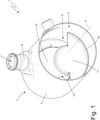
figure 1 is a perspective view of an exhaust gas treatment device according to the invention; -
figure 2 is a further perspective view of the treatment device offigure 1 ; -
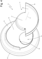
figures 3 and4 are two different perspective views of a mixing body of the treatment device offigure 1 ; and -
figures 5-8 are four different perspective views of a variant of the mixing body offigures 3 and4 . - In
figures 1 and2 ,number 1 indicates, as a whole, an exhaust gas treatment device for an exhaust system of an internal combustion engine operating according to a "Diesel" cycle (i.e. powered by Diesel fuel or the like). - The exhaust
gas treatment device 1 comprises atubular duct 2, which has a centrallongitudinal axis 3 and has a cylindrical shape (namely, has a circular cross section with a constant diameter). Thetubular duct 2 is delimited by atubular side wall 4, which is made of sheet metal and has an exhaust gas inlet opening 5 (shown infigure 1 ), which is arranged in the area of a first base of thetubular duct 2, and an exhaust gas outlet opening 6 (shown infigure 2 ), which is opposite the inlet opening 5 and is arranged in the area of a second base of the tubular duct 2 (obviously, opposite the first base of the tubular duct 2); as a consequence, in use, the exhaust gases flow into thetubular duct 2 through the opening 5, flow through thetubular duct 2 and, then, flow out of thetubular duct 2 through the outlet opening 6. - The
tubular duct 2 further has an injection opening 7, which is obtained through thetubular side wall 4 between the inlet opening 5 and the outlet opening 6 and is designed to receive a reducing substance injector; in particular, around theopening 7 there is atubular housing 8, which projects from thetubular side wall 4 and is configured to receive the injector. The injector is designed to inject into the tubular duct 2 a reducing additive and, in particular, a water solution of urea (i.e. a solution of urea and water); in use, because of the heat of the exhaust gases present inside thetubular duct 2, the urea spontaneously decomposes into isocyanic acid (NHCO) and ammonia (NH3), said ammonia acting as reductant inside a following SCR catalytic convert so as to facilitate the reaction of resolution of NOx molecules into nitrogen (N2) and water (H2O). - According to
figures 3 and4 , thetreatment device 1 comprises a mixing body 9 (a static mixing body, namely without moving parts), which is arranged inside thetubular duct 2, creates a forced path to be followed by the exhaust gases in order to flow from the inlet opening 5 to the outlet opening 6, and is hollow on the inside so that the exhaust gases can flow through it. In particular, themixing body 9 has the function of generating turbulences in the exhaust gases present inside thetubular duct 2 so as to increase the efficiency of the following SCR catalytic converter, thus making the dispersion of ammonia in the exhaust gases more homogeneous. - The
mixing body 9 has aperforated base wall 10 with a circular shape, which faces the outlet opening 6 of thetubular duct 2 and completely engages (closes) the cross section of the tubular duct 2 (namely, the exhaust gases cannot flow past thebase wall 10, except through the hole of thebase wall 10 itself), abase wall 11 with a partially circular shape and without holes, which faces the inlet opening 5 of thetubular duct 2 and only partially engages (closes) the cross section of the tubular duct 2 (namely, the exhaust gases can flow past thebase wall 11 by flowing beside thebase wall 11 itself), and atubular side wall 12, which joins thebase wall 10 to thebase wall 11 and has an inlet opening 13, which leads into themixing body 9. - The
base walls mixing body 9 and thetubular side wall 12 of themixing body 9 are coaxial to thetubular duct 2 and, therefore, share with thetubular duct 2 the same centrallongitudinal symmetry axis 3. - The
base wall 10 of themixing body 9 has one single outlet opening 14 with a circular shape, so that the exhaust gases flowing into themixing body 9 through the inlet opening 13 can subsequently flow out of themixing body 9 and quickly reach the outlet opening 6 of thetubular duct 2 flowing through the outlet opening 14. The exhaust gases flowing into thetubular duct 2 through the inlet opening 5 are necessarily forced to flow into themixing body 9 through the inlet opening 13 and, then, to flow out of themixing body 9 through the outlet opening 14 (since they can only flow out of thetubular body 2 by flowing through the inside of the mixing body 9). The inlet opening 13 of themixing body 9 is arranged perpendicularly relative to the inlet opening 5 of thetubular body 2 and also relative to the outlet opening 14 of the mixing body 9 (and, hence, also relative to the outlet opening 6 of the tubular duct 2); this change in orientation between the inlet opening 5 of thetubular duct 2, the inlet opening 13 of themixing body 9 and the outlet opening 14 of themixing body 9 causes the exhaust gases to gain a (relevant) radial (circumferential) motion component, which is added to the main axial motion component. - Furthermore, the exhaust gases also gain a circumferential motion component, which is added to the main axial motion component, also thanks to the fact that the
base wall 11 of themixing body 9 partially engages (closes) the cross section of thetubular body 2 in the area of the inlet opening 13 of themixing body 9; as a consequence, the exhaust gases flowing into thetubular body 2 through the inlet opening 5 cannot directly reach the inlet opening 13 of themixing body 9 by simply moving in an axial manner, but, first, they have to move around thetubular side wall 12 of themixing body 9 for approximately 180° in order to reach the area behind the inlet opening 13 (not engaged by thebase wall 11 of the mixing body 9), which can be reached by the exhaust gases by axially moving from the inlet opening 5 of thetubular duct 2 to the inlet opening 13 of themixing body 9. - According to a preferred embodiment shown in the accompanying figures, the inlet opening 13 of the
tubular side wall 12 of themixing body 9 is arranged on the opposite side of the injection opening 7, so that the injection opening 7 faces a portion of thetubular side wall 12 without holes; furthermore, as already mentioned above, in the portion of thetubular side wall 12 of themixing body 9 opposite the inlet opening 13, the exhaust gases have a turbulent motion (due to the radial and tangential motion components generated by the particular conformation of the mixing body 9), which enhances an ideal mixing of the reducing agent injected through theinjection opening 7 with the exhaust gases. - According to a referred embodiment shown in
figures 1-4 , thetubular side wall 12 of themixing body 9 has a conical shape, which is tapered from thebase wall 10 to thebase wall 11; namely, thetubular side wall 12 of themixing body 9 has a maximum diameter in the area of thebase wall 10 and has a minimum diameter in the area of thebase wall 11. As a consequence, thetubular side wall 12 of themixing body 9 has, as a whole, the shape of a truncated cone, which is tapered from the outlet opening 6 of thetubular duct 2 to the inlet opening 5 of thetubular duct 2. - The conical shape of the
tubular side wall 12 of themixing body 9 determines a continuous change in the area of the cross section flown through by the exhaust gases flowing towards the outlet opening 6 of thetubular duct 2 and this continuous change determines an increase in the swirling motion of the exhaust gases (which positively affects the mixing of the reducing agent injected through the injection opening 7 with the exhaust gases). - According to a preferred embodiment shown in the accompanying figures, the
base wall 10 of themixing body 9 has an outer diameter which is greater than a diameter of thetubular side wall 12 in the area where it is joined to thebase wall 10; as a consequence, the outlet opening 14 of thebase wall 10 of themixing body 9 also has a diameter which is smaller than the outer diameter of thebase wall 10 and, hence, than a diameter of the outlet opening 6 of thetubular duct 2. - According to a preferred, though non-limiting embodiment shown in the accompanying figures, the inlet opening 13 of the
tubular side wall 12 of themixing body 9 is symmetrically arranged between thebase wall 10 and thebase wall 11 of themixing body 9; namely, the inlet opening 13 is at the same distance from thebase wall 10 and from thebase wall 11 of themixing body 9. - According to a preferred, though non-limiting embodiment shown in the accompanying figures, the inlet opening 13 of the
tubular side wall 12 of themixing body 9 develops for at least 120° (preferably 180°) around the centrallongitudinal axis 3 of thetubular side wall 12. - According to a preferred, though non-limiting embodiment shown in the accompanying figures, the inlet opening 13 of the
tubular side wall 12 of themixing body 9 develops along at least 70% (preferably at least 85%) of an axial size of thetubular side wall 12. - According to a preferred, though non-limiting embodiment shown in the accompanying drawings, the
base wall 10 of themixing body 9 has anannular edge 15, which is perpendicular to thebase wall 10, develops for 360° around the centrallongitudinal axis 3, and rests against and is fixed (welded) to an inner surface of thetubular side wall 4 of thetubular duct 2. - Similarly, the
base wall 11 of themixing body 9 also has anannular edge 16, which is perpendicular to thebase wall 11, develops for 150-210° (preferably 180°) around the centrallongitudinal axis 3, and rests against and is fixed (welded) to an inner surface of thetubular side wall 4. - According to a preferred, though non-limiting embodiment shown in the accompanying drawings, the
base wall 11 of themixing body 9 has acentral portion 17 with a circular shape, which closes the tubular side wall 12 (namely, has the same diameter as the tubular side wall 12) and is separate and relatively far from the inner surface of thetubular side wall 4, and aside portion 18 with the shape of a circular sector, which has a greater diameter than thecentral portion 17, only partially surrounds thecentral portion 17, and extends up to the inner surface of thetubular side wall 4. Theedge 16 is arranged only in the area of theside portion 18 of thebase wall 11 of themixing body 9. From another point of view, thebase wall 11 of themixing body 9 is obtained by joining a first semicircle having the same diameter as thetubular side wall 4 of themixing body 9 and a second semicircle having the same diameter as thetubular side wall 4 of thetubular duct 2; hence, the first semicircle of thebase wall 11 is smaller, is relatively far from the inner surface of thetubular side wall 4, and is not provided with theedge 16, whereas the second semicircle is greater, extents up to the inner surface of thetubular side wall 4, and has theedge 16. -
Figures 5-8 show a different embodiment of thestatic mixing body 9, which is inserted inside thetubular duct 2 and creates a forced path to be followed by the exhaust gases in order to flow from the inlet opening 5 to the outlet opening 6. - The
mixing body 9 shown infigure 5-8 has theperforated base wall 10 with a circular shape, which faces the outlet opening 6 of thetubular duct 2 and completely engages (closes) the cross section of the tubular duct 2 (namely, the exhaust gases cannot flow past thebase wall 10, except through the outlet opening 14 of thebase wall 10 itself), thebase wall 11 with a partially circular shape, which faces the inlet opening 5 of thetubular duct 2 and only partially engages (closes) the cross section of the tubular duct 2 (namely, the exhaust gases can flow past thebase wall 11 by flowing beside thebase wall 11 itself), and thetubular side wall 12, which joins thebase wall 10 to thebase wall 11 and has the inlet opening 13, which leads into themixing body 9. - In the
mixing body 9 shown infigures 5-8 , thebase wall 11 has a large plurality of small throughholes 19 beside one another; in particular, there are different dozens of through holes 19 (approximately 80-100 throughholes 19 in the embodiment shown infigures 5-8 ). Each throughhole 19 has a diameter ranging from 1 to 3 mm, which means that the diameter of each throughhole 19 is equal to a small fraction of a diameter of thetubular duct 2; for example, the diameter of each throughhole 19 is equal to 1-3% of the diameter of thetubular duct 2. According to a different embodiment which is not shown herein, thebase wall 11 of themixing body 9 shown in thefigures 5-8 is not provided with the through holes 19 (like thebase wall 11 of themixing body 9 shown infigures 1-4 ). According to a preferred embodiment, the throughholes 19 are arranged in thesole side portion 18 of thebase wall 11 and, in particular, in an area opposite and far from thecentral portion 17 of the base wall 11 (namely, thecentral portion 17 of thebase wall 11 is completely free from through holes). - It should be pointed out that the through
holes 19 allow only a modest fraction of the exhaust gases coming from the inlet opening 5 of thetubular body 2 to flow through thebase wall 11 of the mixingbody 9 moving in an axial manner, whereas the main part of the exhaust gases coming from the inlet opening 5 of thetubular body 2 is forced to flow around thetubular side wall 12 of themixing body 9 for approximately 180° in order to reach the area behind the inlet opening 13 (not engaged by thebase wall 11 of the mixing body 9), which can be reached by the exhaust gases by axially moving from the inlet opening 5 of thetubular duct 2 to the inlet opening 13 of themixing body 9. - In the embodiment shown in
figures 1-4 , thetubular side wall 12 of themixing body 9 has a conical shape, which is tapered from thebase wall 10 to thebase wall 11; on the other hand, in the embodiment shown infigures 5-8 , thetubular side wall 12 of themixing body 9 has a cylindrical shape (namely, with a constant diameter). - In the embodiment shown in
figures 5-8 , thebase wall 11 has twopanels 20, which prolong the edge 16 (namely, build a local extension of theedge 16 without gaps) at the two opposite ends of theside wall 12 and are arranged radially (perpendicularly) relative to theside wall 12. Namely, themixing body 9 comprises the twopanels 20, which are arranged radially (perpendicularly) relative to theside wall 12, are perpendicular to thebase wall 11, and extend from opposite ends of theside wall 12 up to thetubular duct 2. Obviously, the twopanels 20 have a smaller radial extension than theside wall 12 so as not to completely obstruct the path of the exhaust gases towards the inlet opening 13 of themixing body 9. The function of the twopanels 20 is that of making more winding the path of the exhaust gases that, from the inlet opening 5 of thetubular duct 2, have to reach the inlet opening 13 of themixing body 9 in order to get to the outlet opening 6 of thetubular duct 2. - In the embodiment shown in
figures 5-8 , the mixingbody 9 consists of three distinct and separate pieces joined (welded) to one another: a first piece comprising thebase wall 11, a second piece comprising theside wall 12, and a third piece comprising thebase wall 10. Again, in the embodiment shown infigures 5-8 , the mixingbody 9 is obtained by joining three initially distinct and separate pieces: a first piece comprising thebase wall 11 and part of theside wall 12 having theinlet opening 13, a second piece comprising the remaining part of theside wall 12 without theinlet opening 13, and a third piece comprising thebase wall 10; the first piece and the second piece making up the mixingbody 9 interlock by means of the respective parts of theside wall 12, which are manufactured so as to be partially inserted into one another. - According to a different embodiment which is not shown herein, the
tubular duct 2 could also house an oxidation catalytic converter arranged upstream of the mixing body 9 (namely, the first one to be flown through by the exhaust gases) and/or a SCR (Selective Catalytic Reduction) catalytic converter for the after-treatment of NOx (NO and NO2) molecules and arranged downstream of the mixing body 9 (namely, the last one to be flown through by the exhaust gases); the SCR catalytic converter could also integrate a particular filter. - The embodiments described herein can be combined with one another.
- The
treatment device 1 described above has numerous advantages. - First of all, the
treatment device 1 described above offers an ideal balance between the opposing needs of effectiveness (namely, of ensuring a proper mixing of the exhaust gases) and of efficiency (namely, of causing limited load losses in the exhaust gases). In other words, thetreatment device 1 described above has, at the same time, a high effectiveness (namely, ensures a proper mixing of the exhaust gases) and a high efficiency (namely, causes limited load losses in the exhaust gases). - Furthermore, the
treatment device 1 described above is particularly sturdy (hence, offers a long operating life and a very low risk of breaking), since it consists of a few parts. - The
treatment device 1 described above has particularly small sizes (especially axial sizes) and a modest overall weight. - Finally, the
treatment device 1 described above is simple and economic to be manufactured, since it consists of a few parts with a non-complicated shape and easy to be joined with standard annular welds. -
- 1
- treatment device
- 2
- tubular duct
- 3
- central axis
- 4
- tubular side wall
- 5
- inlet opening
- 6
- outlet opening
- 7
- injection opening
- 8
- tubular housing
- 9
- mixing body
- 10
- base wall
- 11
- base wall
- 12
- tubular side wall
- 13
- inlet opening
- 14
- outlet opening
- 15
- annular edge
- 16
- edge
- 17
- central portion
- 18
- side portion
- 19
- through holes
- 20
- panels
Claims (17)
- An exhaust gas treatment device (1) for an exhaust system of an internal combustion engine; the treatment device (1) comprises:a tubular duct (2), which is delimited by a first tubular side wall (4) and has a first exhaust gas inlet opening (5) arranged in the area of a first base of the tubular duct (2), a first exhaust gas outlet opening (6) opposite the first inlet opening (5) and arranged in the area of a second base of the tubular duct (2), and an injection opening (7), which is obtained through the first tubular side wall (4) between the first inlet opening (5) and the first outlet opening (6) and is designed to receive an injector for a reducing substance; anda mixing body (9), which is arranged inside the tubular duct (2), creates a forced path to be followed by the exhaust gases in order to flow from the first inlet opening (5) to the first outlet opening (6), and is hollow on the inside so that the exhaust gases can flow through it;wherein the mixing body (9) has a first perforated base wall (10) with a circular shape, which faces the first outlet opening (6) of the tubular duct (2) and completely engages the cross section of the tubular duct (2), a second base wall (11) with a partially circular shape, which faces the first inlet opening (5) of the tubular duct (2) and only partially engages the cross section of the tubular duct (2) ;the treatment device (1) is characterized in that the mixing body (9) has a second tubular side wall (12), which joins the first base wall (10) to the second base wall (11) and has a second inlet opening (13) leading into the mixing body (9).
- The treatment device (1) according to claim 1, wherein the second inlet opening (13) develops for at least 120°, preferably 180°, around a central longitudinal axis (3) of the second tubular side wall (12).
- A treatment device (1) according claim 1 or 2, wherein the second tubular side wall (12) has a conical shape, which is tapered from the first base wall (10) to the second base wall (11).
- The treatment device (1) according to claim 1 or 2, wherein the second tubular side wall (12) has a cylindrical shape with a constant diameter.
- The treatment device (1) according to one of the claims from 1 to 4, wherein the second base wall (11) has a plurality of through holes (19) beside one another.
- The treatment device (1) according to one of the claims from 1 to 5, wherein the second inlet opening (13) is arranged on the opposite side relative to the injection opening (7) so that the injection opening (7) faces a portion of the second tubular side wall (12) without holes.
- The treatment device (1) according to one of the claims from 1 to 6, wherein the first base wall (10) has, at the centre, one single second exhaust gas outlet opening (14) with a circular shape.
- The treatment device (1) according to one of the claims from 1 to 7, wherein the first base wall (10) has a first annular edge (15), which is perpendicular to the first base wall (10), develops for 360° around a central longitudinal axis (3), and rests against an inner surface of the first tubular side wall (4).
- The treatment device (1) according to one of the claims from 1 to 8, wherein the second base wall (11) has a second edge (16), which is perpendicular to the second base wall (11), develops for 150-210°, preferably 180°, around a central longitudinal axis (3), and rests against an inner surface of the first tubular side wall (4).
- The treatment device (1) according to one of the claims from 1 to 9, wherein the second base wall (11) has a central portion (17) with a circular shape, which closes the second tubular side wall (12), and a side portion (18) with the shape of a circular sector, which has a greater diameter than the central portion (17) and only partially surrounds the central portion (17).
- The treatment device (1) according to claim 10, wherein the side portion (18) of the second base wall (11) has a second edge (16), which is perpendicular to the second base wall (11), develops for 180° around a central longitudinal axis (3), and rests against an inner surface of the first tubular side wall (4).
- The treatment device (1) according to claim 10 or 11, wherein the side portion (18) of the second base wall (11) has a plurality of through holes (19) beside one another and the central portion (17) of the second base wall (11) is completely without through holes.
- The treatment device (1) according to one of the claims from 1 to 12, wherein the second base wall (11) is obtained by joining a first semicircle having the same diameter as the second tubular side wall (12) of the mixing body (9) and a second semicircle having the same diameter as the first tubular side wall (4) of the tubular duct (2) and, hence, greater than the first semicircle.
- The treatment device (1) according to one of the claims from 1 to 13, wherein the first base wall (10) has an outer diameter which is greater than a diameter of the second tubular side wall (12) in the area where it is joined to the first base wall (10).
- The treatment device (1) according to one of the claims from 1 to 14, wherein the second base wall (11) partially engages the cross section of the tubular duct (2) in the area of the second inlet opening (13).
- The treatment device (1) according to one of the claims from 1 to 15, wherein the mixing body (9) comprises the two panels (20), which are arranged radially relative to the side wall (12), extend from opposite ends of the side wall (12) up to the tubular duct (2), and have a smaller axial extension than the side wall (12).
- The treatment device (1) according to claim 16, wherein the two panels (20) extend starting from the second base wall (11) and are perpendicular to the second base wall (11).
Applications Claiming Priority (1)
| Application Number | Priority Date | Filing Date | Title |
|---|---|---|---|
| IT102019000006064A IT201900006064A1 (en) | 2019-04-18 | 2019-04-18 | EXHAUST GAS TREATMENT DEVICE FOR AN EXHAUST SYSTEM OF AN INTERNAL COMBUSTION ENGINE |
Publications (2)
| Publication Number | Publication Date |
|---|---|
| EP3726018A1 EP3726018A1 (en) | 2020-10-21 |
| EP3726018B1 true EP3726018B1 (en) | 2022-01-19 |
Family
ID=67384254
Family Applications (1)
| Application Number | Title | Priority Date | Filing Date |
|---|---|---|---|
| EP20170091.1A Not-in-force EP3726018B1 (en) | 2019-04-18 | 2020-04-17 | Exhaust gas treatment device for an exhaust system of an internal combustion engine |
Country Status (5)
| Country | Link |
|---|---|
| US (1) | US11035277B2 (en) |
| EP (1) | EP3726018B1 (en) |
| JP (1) | JP2020183755A (en) |
| CN (1) | CN111828142A (en) |
| IT (1) | IT201900006064A1 (en) |
Families Citing this family (2)
| Publication number | Priority date | Publication date | Assignee | Title |
|---|---|---|---|---|
| EP3760846A1 (en) * | 2019-07-04 | 2021-01-06 | Donaldson Company, Inc. | System for mixing a liquid spray into a gaseous flow and exhaust aftertreatment device comprising same |
| CN119801708A (en) * | 2023-10-11 | 2025-04-11 | 康明斯排放处理公司 | Exhaust mixer assembly |
Family Cites Families (25)
| Publication number | Priority date | Publication date | Assignee | Title |
|---|---|---|---|---|
| US8033104B2 (en) * | 2008-07-09 | 2011-10-11 | Ford Global Technologies, Llc | Selective catalytic reduction (SCR) catalyst injection systems |
| WO2011087527A1 (en) * | 2010-01-12 | 2011-07-21 | Donaldson Company, Inc. | Flow device for exhaust treatment system |
| CN103370508B (en) * | 2010-12-15 | 2016-05-04 | 佛吉亚排气系统有限公司 | Exhaust line with equipment for injecting gaseous reagents |
| US8938954B2 (en) * | 2012-04-19 | 2015-01-27 | Donaldson Company, Inc. | Integrated exhaust treatment device having compact configuration |
| KR101416478B1 (en) * | 2012-08-17 | 2014-07-09 | 세종공업 주식회사 | Mixing module for post treatment exhaust contamination gas decreasing system in diesel engine |
| JP2014190177A (en) * | 2013-03-26 | 2014-10-06 | Toyota Motor Corp | Exhaust cleaning device for internal combustion engine |
| US9238991B2 (en) | 2013-04-29 | 2016-01-19 | GM Global Technology Operations LLC | Internal combustion engine and exhaust aftertreatment system |
| EP3444457B1 (en) * | 2014-02-25 | 2020-04-08 | Donaldson Company, Inc. | Exhaust aftertreatment device |
| US9302223B2 (en) * | 2014-06-13 | 2016-04-05 | Caterpillar Inc. | Mixing element |
| DE102014222698B4 (en) * | 2014-11-06 | 2017-12-14 | Eberspächer Exhaust Technology GmbH & Co. KG | Exhaust after-treatment device with injection section |
| WO2016176076A1 (en) * | 2015-04-30 | 2016-11-03 | Faurecia Emissions Control Technologies, Usa, Llc | Full rotation mixer |
| US9828897B2 (en) * | 2015-04-30 | 2017-11-28 | Faurecia Emissions Control Technologies Usa, Llc | Mixer for a vehicle exhaust system |
| WO2016201441A2 (en) * | 2015-06-12 | 2016-12-15 | Donaldson Company, Inc. | Exhaust treatment device |
| FR3041691B1 (en) * | 2015-09-29 | 2017-12-01 | Faurecia Systemes D'echappement | EXHAUST LINE WITH REAGENT INJECTOR |
| DE102016211703A1 (en) | 2016-06-29 | 2018-01-04 | Robert Bosch Gmbh | Mixer device for an exhaust aftertreatment system of a motor vehicle, exhaust aftertreatment system and motor vehicle |
| JP6756629B2 (en) * | 2017-01-17 | 2020-09-16 | フタバ産業株式会社 | Exhaust gas purification device |
| DE112017007124T5 (en) * | 2017-02-24 | 2019-11-28 | Faurecia Emissions Control Technologies, Usa, Llc | INJEKTORSPRÜHSCHUTZ |
| US10443477B2 (en) * | 2017-04-25 | 2019-10-15 | Tenneco Automotive Operating Company Inc. | Counter-swirl mixer |
| CN109236429B (en) * | 2017-07-11 | 2024-07-19 | 天纳克(苏州)排放系统有限公司 | Tail gas aftertreatment mixing arrangement and encapsulation thereof |
| US11098625B2 (en) * | 2017-08-02 | 2021-08-24 | Robert Bosch Gmbh | Multiple def injection concept for reducing risk of solid deposits formation in diesel aftertreatment systems |
| CN108915831B (en) * | 2017-09-19 | 2021-04-02 | 天纳克(苏州)排放系统有限公司 | Tail gas aftertreatment mixing arrangement |
| EP3492718B1 (en) * | 2017-11-30 | 2020-06-10 | Katcon Global S.A. | Exhaust line for a vehicle |
| JP6826058B2 (en) * | 2018-01-24 | 2021-02-03 | フタバ産業株式会社 | Exhaust gas purification device |
| US10287948B1 (en) * | 2018-04-23 | 2019-05-14 | Faurecia Emissions Control Technologies, Usa, Llc | High efficiency mixer for vehicle exhaust system |
| US10967329B2 (en) * | 2019-02-26 | 2021-04-06 | Faurecia Emissions Control Technologies, Usa, Llc | Automotive exhaust aftertreatment system having a swirl-back mixer |
-
2019
- 2019-04-18 IT IT102019000006064A patent/IT201900006064A1/en unknown
-
2020
- 2020-04-16 US US16/850,876 patent/US11035277B2/en not_active Expired - Fee Related
- 2020-04-17 EP EP20170091.1A patent/EP3726018B1/en not_active Not-in-force
- 2020-04-17 JP JP2020074072A patent/JP2020183755A/en active Pending
- 2020-04-20 CN CN202010312372.3A patent/CN111828142A/en active Pending
Also Published As
| Publication number | Publication date |
|---|---|
| US20200332694A1 (en) | 2020-10-22 |
| IT201900006064A1 (en) | 2020-10-18 |
| CN111828142A (en) | 2020-10-27 |
| EP3726018A1 (en) | 2020-10-21 |
| JP2020183755A (en) | 2020-11-12 |
| US11035277B2 (en) | 2021-06-15 |
Similar Documents
| Publication | Publication Date | Title |
|---|---|---|
| US11767783B2 (en) | System for mixing a liquid spray into a gaseous flow and exhaust aftertreatment device comprising same | |
| US11193412B2 (en) | Automotive exhaust aftertreatment system | |
| US10273855B2 (en) | Exhaust aftertreatment system having mixer assembly | |
| EP2871340B1 (en) | Gaseous reductant delivery devices and systems | |
| US20100186382A1 (en) | Emissions system mounting device with reductant mixing | |
| US20140196441A1 (en) | Reductant aqueous solution mixing device and exhaust aftertreatment device provided with the same | |
| US11428139B2 (en) | Internal swirler tube for exhaust catalyst | |
| KR20110010717A (en) | Exhaust Gas Addition / Treatment Systems and Mixers for Use in the System | |
| GB2416718A (en) | Gas treatment apparatus | |
| US20140007562A1 (en) | Exhaust system having an aftertreatment module | |
| US11035277B2 (en) | Exhaust gas treatment device for an exhaust system of an internal combustion engine | |
| JP6826058B2 (en) | Exhaust gas purification device | |
| WO2024049811A1 (en) | Exhaust aftertreatment system including mixer with injector cone | |
| JP6756629B2 (en) | Exhaust gas purification device | |
| WO2008115841A1 (en) | Fixed auger assembly | |
| CN108252773B (en) | Exhaust gas aftertreatment tank with exhaust gas treatment elements arranged side by side | |
| EP3929415B1 (en) | Exhaust gas treatment device for an exhaust system of an internal combustion engine | |
| EP3924091B1 (en) | Exhaust gas mixing device | |
| CN218407577U (en) | Mixer, exhaust system and internal combustion engine equipment thereof | |
| WO2024163749A1 (en) | Aftertreatment system including mixer with exhaust sampling flange | |
| US12359600B2 (en) | Exhaust aftertreatment apparatus | |
| EP3670857A1 (en) | Efficient mixing of gases in an exhaust aftertreatment system | |
| JP7556829B2 (en) | Exhaust Gas Purification Device | |
| IT201900015150A1 (en) | EXHAUST GAS TREATMENT DEVICE FOR AN EXHAUST SYSTEM OF AN INTERNAL COMBUSTION ENGINE | |
| US20200332692A1 (en) | Direct spray exhaust mixer system |
Legal Events
| Date | Code | Title | Description |
|---|---|---|---|
| PUAI | Public reference made under article 153(3) epc to a published international application that has entered the european phase |
Free format text: ORIGINAL CODE: 0009012 |
|
| STAA | Information on the status of an ep patent application or granted ep patent |
Free format text: STATUS: THE APPLICATION HAS BEEN PUBLISHED |
|
| AK | Designated contracting states |
Kind code of ref document: A1 Designated state(s): AL AT BE BG CH CY CZ DE DK EE ES FI FR GB GR HR HU IE IS IT LI LT LU LV MC MK MT NL NO PL PT RO RS SE SI SK SM TR |
|
| AX | Request for extension of the european patent |
Extension state: BA ME |
|
| STAA | Information on the status of an ep patent application or granted ep patent |
Free format text: STATUS: REQUEST FOR EXAMINATION WAS MADE |
|
| 17P | Request for examination filed |
Effective date: 20210420 |
|
| GRAP | Despatch of communication of intention to grant a patent |
Free format text: ORIGINAL CODE: EPIDOSNIGR1 |
|
| STAA | Information on the status of an ep patent application or granted ep patent |
Free format text: STATUS: GRANT OF PATENT IS INTENDED |
|
| INTG | Intention to grant announced |
Effective date: 20210810 |
|
| GRAS | Grant fee paid |
Free format text: ORIGINAL CODE: EPIDOSNIGR3 |
|
| GRAA | (expected) grant |
Free format text: ORIGINAL CODE: 0009210 |
|
| STAA | Information on the status of an ep patent application or granted ep patent |
Free format text: STATUS: THE PATENT HAS BEEN GRANTED |
|
| AK | Designated contracting states |
Kind code of ref document: B1 Designated state(s): AL AT BE BG CH CY CZ DE DK EE ES FI FR GB GR HR HU IE IS IT LI LT LU LV MC MK MT NL NO PL PT RO RS SE SI SK SM TR |
|
| REG | Reference to a national code |
Ref country code: GB Ref legal event code: FG4D |
|
| REG | Reference to a national code |
Ref country code: CH Ref legal event code: EP |
|
| REG | Reference to a national code |
Ref country code: DE Ref legal event code: R096 Ref document number: 602020001641 Country of ref document: DE |
|
| REG | Reference to a national code |
Ref country code: AT Ref legal event code: REF Ref document number: 1463915 Country of ref document: AT Kind code of ref document: T Effective date: 20220215 |
|
| REG | Reference to a national code |
Ref country code: IE Ref legal event code: FG4D |
|
| REG | Reference to a national code |
Ref country code: LT Ref legal event code: MG9D |
|
| REG | Reference to a national code |
Ref country code: NL Ref legal event code: MP Effective date: 20220119 |
|
| REG | Reference to a national code |
Ref country code: AT Ref legal event code: MK05 Ref document number: 1463915 Country of ref document: AT Kind code of ref document: T Effective date: 20220119 |
|
| PG25 | Lapsed in a contracting state [announced via postgrant information from national office to epo] |
Ref country code: NL Free format text: LAPSE BECAUSE OF FAILURE TO SUBMIT A TRANSLATION OF THE DESCRIPTION OR TO PAY THE FEE WITHIN THE PRESCRIBED TIME-LIMIT Effective date: 20220119 |
|
| PG25 | Lapsed in a contracting state [announced via postgrant information from national office to epo] |
Ref country code: SE Free format text: LAPSE BECAUSE OF FAILURE TO SUBMIT A TRANSLATION OF THE DESCRIPTION OR TO PAY THE FEE WITHIN THE PRESCRIBED TIME-LIMIT Effective date: 20220119 Ref country code: RS Free format text: LAPSE BECAUSE OF FAILURE TO SUBMIT A TRANSLATION OF THE DESCRIPTION OR TO PAY THE FEE WITHIN THE PRESCRIBED TIME-LIMIT Effective date: 20220119 Ref country code: PT Free format text: LAPSE BECAUSE OF FAILURE TO SUBMIT A TRANSLATION OF THE DESCRIPTION OR TO PAY THE FEE WITHIN THE PRESCRIBED TIME-LIMIT Effective date: 20220519 Ref country code: NO Free format text: LAPSE BECAUSE OF FAILURE TO SUBMIT A TRANSLATION OF THE DESCRIPTION OR TO PAY THE FEE WITHIN THE PRESCRIBED TIME-LIMIT Effective date: 20220419 Ref country code: LT Free format text: LAPSE BECAUSE OF FAILURE TO SUBMIT A TRANSLATION OF THE DESCRIPTION OR TO PAY THE FEE WITHIN THE PRESCRIBED TIME-LIMIT Effective date: 20220119 Ref country code: HR Free format text: LAPSE BECAUSE OF FAILURE TO SUBMIT A TRANSLATION OF THE DESCRIPTION OR TO PAY THE FEE WITHIN THE PRESCRIBED TIME-LIMIT Effective date: 20220119 Ref country code: ES Free format text: LAPSE BECAUSE OF FAILURE TO SUBMIT A TRANSLATION OF THE DESCRIPTION OR TO PAY THE FEE WITHIN THE PRESCRIBED TIME-LIMIT Effective date: 20220119 Ref country code: BG Free format text: LAPSE BECAUSE OF FAILURE TO SUBMIT A TRANSLATION OF THE DESCRIPTION OR TO PAY THE FEE WITHIN THE PRESCRIBED TIME-LIMIT Effective date: 20220419 |
|
| PG25 | Lapsed in a contracting state [announced via postgrant information from national office to epo] |
Ref country code: PL Free format text: LAPSE BECAUSE OF FAILURE TO SUBMIT A TRANSLATION OF THE DESCRIPTION OR TO PAY THE FEE WITHIN THE PRESCRIBED TIME-LIMIT Effective date: 20220119 Ref country code: LV Free format text: LAPSE BECAUSE OF FAILURE TO SUBMIT A TRANSLATION OF THE DESCRIPTION OR TO PAY THE FEE WITHIN THE PRESCRIBED TIME-LIMIT Effective date: 20220119 Ref country code: GR Free format text: LAPSE BECAUSE OF FAILURE TO SUBMIT A TRANSLATION OF THE DESCRIPTION OR TO PAY THE FEE WITHIN THE PRESCRIBED TIME-LIMIT Effective date: 20220420 Ref country code: FI Free format text: LAPSE BECAUSE OF FAILURE TO SUBMIT A TRANSLATION OF THE DESCRIPTION OR TO PAY THE FEE WITHIN THE PRESCRIBED TIME-LIMIT Effective date: 20220119 Ref country code: AT Free format text: LAPSE BECAUSE OF FAILURE TO SUBMIT A TRANSLATION OF THE DESCRIPTION OR TO PAY THE FEE WITHIN THE PRESCRIBED TIME-LIMIT Effective date: 20220119 |
|
| PG25 | Lapsed in a contracting state [announced via postgrant information from national office to epo] |
Ref country code: IS Free format text: LAPSE BECAUSE OF FAILURE TO SUBMIT A TRANSLATION OF THE DESCRIPTION OR TO PAY THE FEE WITHIN THE PRESCRIBED TIME-LIMIT Effective date: 20220519 |
|
| REG | Reference to a national code |
Ref country code: DE Ref legal event code: R097 Ref document number: 602020001641 Country of ref document: DE |
|
| PG25 | Lapsed in a contracting state [announced via postgrant information from national office to epo] |
Ref country code: SM Free format text: LAPSE BECAUSE OF FAILURE TO SUBMIT A TRANSLATION OF THE DESCRIPTION OR TO PAY THE FEE WITHIN THE PRESCRIBED TIME-LIMIT Effective date: 20220119 Ref country code: SK Free format text: LAPSE BECAUSE OF FAILURE TO SUBMIT A TRANSLATION OF THE DESCRIPTION OR TO PAY THE FEE WITHIN THE PRESCRIBED TIME-LIMIT Effective date: 20220119 Ref country code: RO Free format text: LAPSE BECAUSE OF FAILURE TO SUBMIT A TRANSLATION OF THE DESCRIPTION OR TO PAY THE FEE WITHIN THE PRESCRIBED TIME-LIMIT Effective date: 20220119 Ref country code: EE Free format text: LAPSE BECAUSE OF FAILURE TO SUBMIT A TRANSLATION OF THE DESCRIPTION OR TO PAY THE FEE WITHIN THE PRESCRIBED TIME-LIMIT Effective date: 20220119 Ref country code: DK Free format text: LAPSE BECAUSE OF FAILURE TO SUBMIT A TRANSLATION OF THE DESCRIPTION OR TO PAY THE FEE WITHIN THE PRESCRIBED TIME-LIMIT Effective date: 20220119 Ref country code: CZ Free format text: LAPSE BECAUSE OF FAILURE TO SUBMIT A TRANSLATION OF THE DESCRIPTION OR TO PAY THE FEE WITHIN THE PRESCRIBED TIME-LIMIT Effective date: 20220119 |
|
| PLBE | No opposition filed within time limit |
Free format text: ORIGINAL CODE: 0009261 |
|
| STAA | Information on the status of an ep patent application or granted ep patent |
Free format text: STATUS: NO OPPOSITION FILED WITHIN TIME LIMIT |
|
| PG25 | Lapsed in a contracting state [announced via postgrant information from national office to epo] |
Ref country code: AL Free format text: LAPSE BECAUSE OF FAILURE TO SUBMIT A TRANSLATION OF THE DESCRIPTION OR TO PAY THE FEE WITHIN THE PRESCRIBED TIME-LIMIT Effective date: 20220119 |
|
| 26N | No opposition filed |
Effective date: 20221020 |
|
| REG | Reference to a national code |
Ref country code: BE Ref legal event code: MM Effective date: 20220430 |
|
| PG25 | Lapsed in a contracting state [announced via postgrant information from national office to epo] |
Ref country code: MC Free format text: LAPSE BECAUSE OF FAILURE TO SUBMIT A TRANSLATION OF THE DESCRIPTION OR TO PAY THE FEE WITHIN THE PRESCRIBED TIME-LIMIT Effective date: 20220119 Ref country code: LU Free format text: LAPSE BECAUSE OF NON-PAYMENT OF DUE FEES Effective date: 20220417 |
|
| PG25 | Lapsed in a contracting state [announced via postgrant information from national office to epo] |
Ref country code: SI Free format text: LAPSE BECAUSE OF FAILURE TO SUBMIT A TRANSLATION OF THE DESCRIPTION OR TO PAY THE FEE WITHIN THE PRESCRIBED TIME-LIMIT Effective date: 20220119 Ref country code: BE Free format text: LAPSE BECAUSE OF NON-PAYMENT OF DUE FEES Effective date: 20220430 |
|
| PG25 | Lapsed in a contracting state [announced via postgrant information from national office to epo] |
Ref country code: IE Free format text: LAPSE BECAUSE OF NON-PAYMENT OF DUE FEES Effective date: 20220417 |
|
| PG25 | Lapsed in a contracting state [announced via postgrant information from national office to epo] |
Ref country code: IT Free format text: LAPSE BECAUSE OF FAILURE TO SUBMIT A TRANSLATION OF THE DESCRIPTION OR TO PAY THE FEE WITHIN THE PRESCRIBED TIME-LIMIT Effective date: 20220119 |
|
| REG | Reference to a national code |
Ref country code: CH Ref legal event code: PL |
|
| PG25 | Lapsed in a contracting state [announced via postgrant information from national office to epo] |
Ref country code: LI Free format text: LAPSE BECAUSE OF NON-PAYMENT OF DUE FEES Effective date: 20230430 Ref country code: CH Free format text: LAPSE BECAUSE OF NON-PAYMENT OF DUE FEES Effective date: 20230430 |
|
| PG25 | Lapsed in a contracting state [announced via postgrant information from national office to epo] |
Ref country code: MK Free format text: LAPSE BECAUSE OF FAILURE TO SUBMIT A TRANSLATION OF THE DESCRIPTION OR TO PAY THE FEE WITHIN THE PRESCRIBED TIME-LIMIT Effective date: 20220119 Ref country code: CY Free format text: LAPSE BECAUSE OF FAILURE TO SUBMIT A TRANSLATION OF THE DESCRIPTION OR TO PAY THE FEE WITHIN THE PRESCRIBED TIME-LIMIT Effective date: 20220119 |
|
| PGFP | Annual fee paid to national office [announced via postgrant information from national office to epo] |
Ref country code: GB Payment date: 20240320 Year of fee payment: 5 |
|
| PG25 | Lapsed in a contracting state [announced via postgrant information from national office to epo] |
Ref country code: HU Free format text: LAPSE BECAUSE OF FAILURE TO SUBMIT A TRANSLATION OF THE DESCRIPTION OR TO PAY THE FEE WITHIN THE PRESCRIBED TIME-LIMIT; INVALID AB INITIO Effective date: 20200417 |
|
| PGFP | Annual fee paid to national office [announced via postgrant information from national office to epo] |
Ref country code: FR Payment date: 20240320 Year of fee payment: 5 |
|
| PG25 | Lapsed in a contracting state [announced via postgrant information from national office to epo] |
Ref country code: TR Free format text: LAPSE BECAUSE OF FAILURE TO SUBMIT A TRANSLATION OF THE DESCRIPTION OR TO PAY THE FEE WITHIN THE PRESCRIBED TIME-LIMIT Effective date: 20220119 |
|
| PGFP | Annual fee paid to national office [announced via postgrant information from national office to epo] |
Ref country code: DE Payment date: 20240320 Year of fee payment: 5 |
|
| PG25 | Lapsed in a contracting state [announced via postgrant information from national office to epo] |
Ref country code: MT Free format text: LAPSE BECAUSE OF FAILURE TO SUBMIT A TRANSLATION OF THE DESCRIPTION OR TO PAY THE FEE WITHIN THE PRESCRIBED TIME-LIMIT Effective date: 20220119 |
|
| REG | Reference to a national code |
Ref country code: DE Ref legal event code: R119 Ref document number: 602020001641 Country of ref document: DE |
|
| GBPC | Gb: european patent ceased through non-payment of renewal fee |
Effective date: 20250417 |
|
| PG25 | Lapsed in a contracting state [announced via postgrant information from national office to epo] |
Ref country code: DE Free format text: LAPSE BECAUSE OF NON-PAYMENT OF DUE FEES Effective date: 20251104 |
|
| PG25 | Lapsed in a contracting state [announced via postgrant information from national office to epo] |
Ref country code: GB Free format text: LAPSE BECAUSE OF NON-PAYMENT OF DUE FEES Effective date: 20250417 |
|
| PG25 | Lapsed in a contracting state [announced via postgrant information from national office to epo] |
Ref country code: FR Free format text: LAPSE BECAUSE OF NON-PAYMENT OF DUE FEES Effective date: 20250430 |