EP3725681B1 - Wearable power modules with distributed energy storage systems - Google Patents
Wearable power modules with distributed energy storage systems Download PDFInfo
- Publication number
- EP3725681B1 EP3725681B1 EP19215245.2A EP19215245A EP3725681B1 EP 3725681 B1 EP3725681 B1 EP 3725681B1 EP 19215245 A EP19215245 A EP 19215245A EP 3725681 B1 EP3725681 B1 EP 3725681B1
- Authority
- EP
- European Patent Office
- Prior art keywords
- pressure vessel
- harness
- leg portion
- energy source
- turboalternator
- Prior art date
- Legal status (The legal status is an assumption and is not a legal conclusion. Google has not performed a legal analysis and makes no representation as to the accuracy of the status listed.)
- Active
Links
Images



Classifications
-
- B—PERFORMING OPERATIONS; TRANSPORTING
- B64—AIRCRAFT; AVIATION; COSMONAUTICS
- B64C—AEROPLANES; HELICOPTERS
- B64C39/00—Aircraft not otherwise provided for
- B64C39/02—Aircraft not otherwise provided for characterised by special use
- B64C39/026—Aircraft not otherwise provided for characterised by special use for use as personal propulsion unit
-
- F—MECHANICAL ENGINEERING; LIGHTING; HEATING; WEAPONS; BLASTING
- F41—WEAPONS
- F41H—ARMOUR; ARMOURED TURRETS; ARMOURED OR ARMED VEHICLES; MEANS OF ATTACK OR DEFENCE, e.g. CAMOUFLAGE, IN GENERAL
- F41H1/00—Personal protection gear
- F41H1/02—Armoured or projectile- or missile-resistant garments; Composite protection fabrics
-
- F—MECHANICAL ENGINEERING; LIGHTING; HEATING; WEAPONS; BLASTING
- F01—MACHINES OR ENGINES IN GENERAL; ENGINE PLANTS IN GENERAL; STEAM ENGINES
- F01D—NON-POSITIVE DISPLACEMENT MACHINES OR ENGINES, e.g. STEAM TURBINES
- F01D15/00—Adaptations of machines or engines for special use; Combinations of engines with devices driven thereby
- F01D15/10—Adaptations for driving, or combinations with, electric generators
-
- F—MECHANICAL ENGINEERING; LIGHTING; HEATING; WEAPONS; BLASTING
- F02—COMBUSTION ENGINES; HOT-GAS OR COMBUSTION-PRODUCT ENGINE PLANTS
- F02C—GAS-TURBINE PLANTS; AIR INTAKES FOR JET-PROPULSION PLANTS; CONTROLLING FUEL SUPPLY IN AIR-BREATHING JET-PROPULSION PLANTS
- F02C6/00—Plural gas-turbine plants; Combinations of gas-turbine plants with other apparatus; Adaptations of gas-turbine plants for special use
- F02C6/04—Gas-turbine plants providing heated or pressurised working fluid for other apparatus, e.g. without mechanical power output
-
- F—MECHANICAL ENGINEERING; LIGHTING; HEATING; WEAPONS; BLASTING
- F02—COMBUSTION ENGINES; HOT-GAS OR COMBUSTION-PRODUCT ENGINE PLANTS
- F02C—GAS-TURBINE PLANTS; AIR INTAKES FOR JET-PROPULSION PLANTS; CONTROLLING FUEL SUPPLY IN AIR-BREATHING JET-PROPULSION PLANTS
- F02C9/00—Controlling gas-turbine plants; Controlling fuel supply in air- breathing jet-propulsion plants
- F02C9/26—Control of fuel supply
- F02C9/28—Regulating systems responsive to plant or ambient parameters, e.g. temperature, pressure, rotor speed
-
- F—MECHANICAL ENGINEERING; LIGHTING; HEATING; WEAPONS; BLASTING
- F41—WEAPONS
- F41H—ARMOUR; ARMOURED TURRETS; ARMOURED OR ARMED VEHICLES; MEANS OF ATTACK OR DEFENCE, e.g. CAMOUFLAGE, IN GENERAL
- F41H5/00—Armour; Armour plates
- F41H5/06—Shields
- F41H5/08—Shields for personal use, i.e. hand held shields
-
- H—ELECTRICITY
- H02—GENERATION; CONVERSION OR DISTRIBUTION OF ELECTRIC POWER
- H02J—ELECTRIC POWER NETWORKS; CIRCUIT ARRANGEMENTS OR SYSTEMS FOR SUPPLYING OR DISTRIBUTING ELECTRIC POWER; SYSTEMS FOR STORING ELECTRIC ENERGY
- H02J3/00—Circuit arrangements for AC mains or AC distribution networks
- H02J3/36—Arrangements for transfer of electric power between AC networks via high-voltage DC [HVDC] links; Arrangements for transfer of electric power between generators and networks via HVDC links
Definitions
- the present disclosure generally relates to power modules, and more particularly to wearable power modules with distributed energy systems.
- the energy storage system includes a harness with a torso segment and a limb segment, a turboalternator supported by the torso segment of the harness, and a chemical energy source.
- the chemical energy source is in fluid communication with the turboalternator and is supported by the harness, the chemical energy source is supported on the limb segment of the harness in a distributed arrangement to allow for support of a mechanical load by the torso segment of the harness.
- further embodiments may include wherein the limb segment of the harness includes a left-leg portion and a right-leg portion, wherein the chemical energy source is distributed between the left-leg portion and right-leg portion of the limb segment.
- further embodiments may include wherein the chemical energy source comprises a first pressure vessel and one or more second pressure vessel, the one or more second pressure vessel in fluid communication with the turboalternator.
- further embodiments may include wherein the first pressure vessel is fluidly connected to the turboalternator by the one or more second pressure vessel.
- further embodiments may include wherein the first pressure vessel contains a compressed gas charge, wherein the one or more second pressure vessel contains a fuel charge.
- further embodiments may include wherein the one or more second pressure vessel contains a liquid fuel charge, wherein the liquid fuel charge is pressurized by a compressed gas communicated by the first pressure vessel.
- limb segment of the harness comprises a left-leg portion and right-leg portion, wherein the first pressure vessel is supported by one of the left-leg portion and the right-leg portion, wherein the one or more second pressure vessel is supported by the other of left-leg portion and the right-leg portion.
- further embodiments may include a turbine speed control valve fluidly connecting the chemical energy source to the turboalternator.
- further embodiments may include wherein the torso segment of the harness has a shoulder portion and a lower back portion, wherein the turboalternator is supported by the lower back portion of the torso segment, and further comprising a mechanical load supported by the lower back portion of the harness.
- further embodiments may include an electrical load electrically connected to the turboalternator.
- further embodiments may include a ballistic shield at least partially enclosing the chemical energy source.
- further embodiments may include wherein the ballistic shield comprises an outer case, wherein the chemical energy source is arranged between the harness and the outer case of the ballistic shield.
- the ballistic shield includes an inner case arranged between the chemical energy source and the harness, an outer case arranged on a side of the chemical energy source opposite the inner case, and a shear thickening fluid disposed between the inner case and the outer case, the shear thickening fluid enveloping at least a portion of the chemical energy source.
- further embodiments may include wherein the ballistic shield comprises a fiber reinforced ceramic material.
- further embodiments may include wherein the chemical energy source comprises a first pressure vessel and one or more second pressure vessel, wherein the ballistic shield encloses the first pressure vessel and the one or more second pressure vessel.
- a wearable power module includes an energy storage system as described above.
- the chemical energy source includes a first pressure vessel and one or more second pressure vessel, the one or more second pressure vessel in fluid communication with the turboalternator, wherein the limb segment of the harness includes a left-leg portion and a right-leg portion, wherein the first pressure vessel and the one or more second pressure vessel are distributed between the left-leg portion and right-leg portion of the limb segment; and a ballistic shield at least partially enclosing the first pressure vessel and the one or more second pressure vessel.
- further embodiments may include that the torso segment of the harness has a shoulder portion and a lower back portion, wherein the turboalternator is supported by the lower back portion of the torso segment, and the wearable power module additionally includes a mechanical load including a cargo pack supported by the lower back portion of the harness, and an electrical load electrically connected to the turboalternator.
- the exoskeleton includes at least one of a load-carrying member and load-transfer member and an energy storage system as described above.
- the chemical energy source is supported by the exoskeleton through the harness of the energy storage system.
- the distribution of the energy storage system is such that chemical energy for the wearable power module leaves the shoulder portion of a harness available for a mechanical load, such as a cargo pack.
- a turboalternator is provided to provide electrical power for one of more electrical loads and is distributed such that the shoulder portion of the harness is available for the mechanical load.
- FIG. 1 a partial view of an exemplary embodiment of an energy storage system constructed in accordance with the disclosure is shown in FIG. 1 and is designated generally by reference character 100.
- FIGS. 2-6 Other embodiments of energy storage systems, wearable power modules, and exoskeletons having distributed energy systems in accordance with the present disclosure, or aspects thereof, are provided in FIGS. 2-6 , as will be described.
- the systems and methods described herein can be used for generating electrical power from a wearable power module, such as military applications, though the present disclosure is not limited to military applications or to wearable application in general.
- the distributed energy system is configured to provide chemical energy to a turboalternator 102 and includes a harness 104 and a chemical energy source 105 (shown in FIG. 3 ) with a plurality of fuel pressure vessels 106 and a plurality of compressed gas pressure vessels 108.
- the harness 104 includes a torso segment 110 and a limb segment 112.
- the torso segment 110 is configured and adapted to be worn by a user 10, e.g., a soldier, and has a shoulder portion 114 and a lower back portion 116.
- the shoulder portion 114 is configured to be suspended from the shoulders of the user 10.
- the lower back portion 116 is configured to be suspended from the lower back of the user 10.
- fuel encompasses mono-propellants, which can provide a flow of high pressure decomposition products without an oxidizer, and liquid fuels requiring an oxidizer to generate high pressure combustion products.
- the limb segment 112 is configured and adapted to be worn by the user 10 and has a right-leg portion 118 and a left-leg portion 120.
- the right-leg portion 118 is configured to be suspended from the right-leg of the user 10.
- the left-leg portion 120 is configured to be suspended from the left-leg of the user 10.
- the harness 104 can be included in an exoskeleton 122 having a one or more support member element 124 and one or more load transfer member 126 operably connected to the one or more support member 124 to manipulate loads, e.g., the mechanical load 12, according instructions received from the user 10.
- the turboalternator 102 is supported by the torso segment 110 of the harness 104. More specifically, the turboalternator is supported by the lower back portion 116 of the torso segment 110 of the harness 104.
- the fuel pressure vessels 106 and the compressed gas pressure vessels 108 are supported by the limb segment 112 of the harness 104, and are each distributed on the limb segment of the harness 104. It is contemplated that one or more of the fuel pressure vessels 106 be supported by the right-leg portion 118 of the harness 104 and that one or more of the fuel pressure vessels 106 be supported by the left-leg portion 120 of the harness 104.
- the compressed gas pressure vessels 108 be supported by the right-leg portion 118 of the harness 104 and one or more of the compressed gas pressure vessels 108 be supported by the left-leg portion 120 of the harness 104.
- the mechanical load 12 includes a cargo pack 14, e.g., a rucksack-type military cargo pack, which is supported by the harness 104 above the turboalternator 102, the fuel pressure vessels 106, and the compressed gas pressure vessels 108.
- the turboalternator 102 is shown.
- the turboalternator 102 is configured and adapted to convert chemical energy from the chemical energy source 105 (shown in FIG. 3 ) contained in one or more of the fuel pressure vessels 106 (shown in FIG. 1 ) into mechanical energy, and therefrom electrical energy for powering an electrical load 16.
- the turboalternator 102 includes a power converter 128, a permanent magnet generator 130, and an interconnect shaft 132.
- the turboalternator 102 also includes a turbine 134, a diffuser 136, and a gas generator 138.
- the gas generator 138 fluidly connects the energy storage system 100 with the turbine 134, includes a decomposition or combustion chamber 140, and is configured and adapted to generate a flow of high pressure combustion products 18 from a fuel flow 20 provided to the decomposition or combustion chamber 140 by the energy storage system 100.
- the high pressure combustion products 18 are communicated to the turbine 134.
- a mono-propellant is provided to a decomposition chamber and decomposed therein without utilization of an oxidizer to generate high pressure decomposition products.
- a liquid fuel and an oxidizer e.g., compressed air, can be provided to a combustion chamber and combusted therein to generate high pressure combustion products.
- the turbine 134 fluidly connects the gas generator 138 with the ambient environment 22 and is operably connected to the permanent magnet generator 130 by the interconnect shaft 132.
- the turbine 134 receives the high pressure combustion products 18, expands the high pressure combustion products 18 as the high pressure combustion products 18 traverse the turbine 134, extracts work from the high pressure combustion products 18 as they traverse the turbine 134, and communicate the work to the permanent magnet generator 130 as mechanical rotation R through the interconnect shaft 132.
- the high pressure combustion products 18 are communicated to the ambient environment 22 through the diffuser 136.
- the diffuser 136 converts the remaining dynamic energy of the turbine exhaust into static pressure, which increases the available pressure ratio across the turbine 134 and turbine nozzles.
- the turbine 134 includes an impulse turbine 140, providing radial compactness to the turbine 134.
- the turbine 134 can include a single stage 142, providing axial compactness to the turbine 134.
- the permanent magnet generator 130 is operatively associated with the turbine 134, is electrically connected to the power converter 128, and is configured and adapted to generate variable frequency alternating current (AC) power 24 using the mechanical rotation R provided to the permanent magnet generator 130 by the turbine 134 through the interconnect shaft 132.
- the permanent magnet generator 130 includes one or more permanent magnet 144, fixed in rotation relative to the interconnect shaft 132, and supported for rotation relative to a stator winding 146.
- the permanent magnet 144 generates magnetic flux, which is communicated to the stator winding 146 during rotation and which induces a flow of alternating current in the stator winding 146.
- the power converter 128 electrically connects the stator winding 146 with the electrical load 16 and is configured and adapted to convert the variable frequency AC power 24 provided by the permanent magnet generator 130 into direct current (DC) power 32. Conversion is accomplished by a rectifier circuit 148, which in certain embodiments is a rectifier circuit 150. In certain embodiments the rectifier circuit 150 includes a diode bridge, which passively rectifies the variable frequency AC power 24 into DC power 32 with a relatively simple circuit arrangement.
- the energy storage system includes the fuel pressure vessels 106 and the compressed gas pressure vessels 108.
- a first compressed gas pressure vessel 108A, a first fuel pressure vessel 106A, and one or more second fuel pressure vessel 106B are supported by the right-leg portion 118 of the limb segment 112 of the harness 104.
- the first compressed gas pressure vessel 108A contains a compressed gas charge 34.
- the compressed gas charge 34 includes an inert gas, such as substantially pure nitrogen by way of non-limiting example.
- the first fuel pressure vessel 106A and the one or more second fuel pressure vessel 106B respectively contain a fuel charge 36.
- the fuel charge 36 is a liquid fuel charge, such as a kerosene-based liquid fuel like JP-8 in conjunction with an oxidizer in a combustion chamber by way of non-limiting example.
- the first fuel pressure vessel 106A and the one or more second fuel pressure vessel 106B are in fluid communication with the turboalternator 102. More specifically, the first fuel pressure vessel 106A is connected to the turboalternator 102 in parallel with the one or more second fuel pressure vessel 106B. In this respect a throttle valve 152 fluidly connects the first fuel pressure vessel 106A and the one or more second fuel pressure vessel 106B to the turboalternator 102, the throttle valve 152 controlling the speed of the turbine 134 by throttling the rate of the flow of the fuel charge 36 to the turbine 134. It is contemplated that the compressed gas charge 34 from the compressed gas pressure vessel 108 drive fuel from the liquid fuel charge 36 to the turboalternator 102. In certain embodiments the energy storage system 100 provides a liquid fuel 38 to the turboalternator 102.
- the first compressed gas pressure vessel 108A is fluidly coupled to the turboalternator 102 by the first fuel pressure vessel 106A and the one or more second fuel pressure vessel 106B, respectively, in a blowdown arrangement.
- the first compressed gas pressure vessel 108A is fluidly connected to the first fuel pressure vessel 106A and the one or more second fuel pressure vessel 106B at the right-leg portion 118 to pressurize the fuel contained in both the first fuel pressure vessel 106A and the one or more second fuel pressure vessel 106B.
- pressurizing the fuel charge 36 within the first fuel pressure vessel 106A and the one or more second fuel pressure vessel 106B using the compressed gas charge 34 within the first compressed gas pressure vessel 108A simplifies the control scheme for delivery of fuel to the turboalternator 102, the turbine speed control valve 152 employing a variable orifice structure in certain embodiments.
- the second compressed gas pressure vessel 108B is similar to the first compressed gas pressure vessel 108A, and is additionally supported on the left-leg portion 120 of the limb segment 112 of the harness 104. Further, the second compressed gas pressure vessel 108B is connected to the turboalternator 102 through both a third fuel pressure vessel 108C and one or more fourth fuel pressure vessel 108D. As will be appreciated by those of skill in the art in view of the present disclosure, this distributes fuel contained in the energy storage system 100 both between the plurality of fuel pressure vessels 106 supported on the left-leg portion 120 and the right-leg portion 118 of the limb segment 112 of the harness 104.
- the ballistic shield arrangement 160 is configured an adapted to provide ballistic protection and includes a left-leg ballistic shield 162 (shown in FIG. 5 ) and a right-leg ballistic shield 164.
- the right-leg ballistic shield 164 includes a fiber reinforced ceramic material 172.
- the fiber reinforced ceramic material 172 is configured and adapted to fragment an incoming projectile upon impact. Examples of suitable fiber-reinforced ceramic materials include those described in U.S. Patent No. 5,970,843 to Strasser et al., issued on October 26, 1999 , the contents of which are incorporated herein by reference in its entirety.
- the left-leg ballistic shield 162 includes an inner case 166, an outer case 168, and a shear thickening fluid 170.
- the inner case 166 is arranged between the first fuel pressure vessel 106A and the left-leg portion 120 of the harness 104. More specifically, the inner case 166 is arranged between each of the first fuel pressure vessel 106A, the one or more second fuel pressure vessel 106B (shown in FIG. 1 ), and the first compressed gas pressure vessel 108A (shown in FIG. 1 ).
- the outer case 168 is arranged on a side of the first fuel pressure vessel 106A opposite the inner case 166. More specifically, the outer case 168 is arranged on a side of the first fuel pressure vessel 106A, the one or more second fuel pressure vessel 106B, and the first compressed gas pressure vessel 108A opposite the inner case 166.
- the shear thickening fluid 170 is disposed between the inner case 166 and the outer case 168. In this respect the shear thickening fluid 170 envelopes the first fuel pressure vessel 106A, the one or more second fuel pressure vessel 106B, and the first compressed gas pressure vessel 108A in a cavity defined between the outer case 168 and the inner case 166.
- suitable shear thickening fluids include ArmourGel ® , available from the Dow Corning Company of Midland, Michigan.
- the left-leg ballistic shield 162 at least partially encloses the first fuel pressure vessel 106A, the one or more second fuel pressure vessel 106B, and the first compressed gas pressure vessel 108A.
- the right-leg ballistic shield 164 is similar to the left-leg ballistic shield 162, and additionally encloses the third pressure vessel 106C, the one or more fourth pressure vessel 106D, and the second compressed gas pressure vessel 108B.
Landscapes
- Engineering & Computer Science (AREA)
- General Engineering & Computer Science (AREA)
- Chemical & Material Sciences (AREA)
- Combustion & Propulsion (AREA)
- Mechanical Engineering (AREA)
- Power Engineering (AREA)
- Aviation & Aerospace Engineering (AREA)
- Other Liquid Machine Or Engine Such As Wave Power Use (AREA)
- Filling Or Discharging Of Gas Storage Vessels (AREA)
Description
- The present disclosure generally relates to power modules, and more particularly to wearable power modules with distributed energy systems.
- Military planners commonly look for ways to provide soldiers with improved protection and mobility, greater firepower, and the ability to carry additional equipment into battle without feeling the effects of fatigue. Various types of electrically powered equipment have been developed with these needs in mind, the power requirements of such equipment generally being accommodated by rechargeable batteries. In some applications the power requirement of the electrically powered equipment can exceed the capability of rechargeable batteries to provide electric power. In such situations it may be necessary to either limit the duration of the operation or tether the equipment to a power source.
- Such power sources have generally been acceptable for their intended purpose. However, there remains a need for improved sources of electrical power. The present disclosure provides a solution to this need.
- An energy storage system for wearable power modules is provided. The energy storage system includes a harness with a torso segment and a limb segment, a turboalternator supported by the torso segment of the harness, and a chemical energy source. The chemical energy source is in fluid communication with the turboalternator and is supported by the harness, the chemical energy source is supported on the limb segment of the harness in a distributed arrangement to allow for support of a mechanical load by the torso segment of the harness.
- In addition to one or more of the features described above, or as an alternative, further embodiments may include wherein the limb segment of the harness includes a left-leg portion and a right-leg portion, wherein the chemical energy source is distributed between the left-leg portion and right-leg portion of the limb segment.
- In addition to one or more of the features described above, or as an alternative, further embodiments may include wherein the chemical energy source comprises a first pressure vessel and one or more second pressure vessel, the one or more second pressure vessel in fluid communication with the turboalternator.
- In addition to one or more of the features described above, or as an alternative, further embodiments may include wherein the first pressure vessel is fluidly connected to the turboalternator by the one or more second pressure vessel.
- In addition to one or more of the features described above, or as an alternative, further embodiments may include wherein the first pressure vessel contains a compressed gas charge, wherein the one or more second pressure vessel contains a fuel charge.
- In addition to one or more of the features described above, or as an alternative, further embodiments may include wherein the one or more second pressure vessel contains a liquid fuel charge, wherein the liquid fuel charge is pressurized by a compressed gas communicated by the first pressure vessel.
- In addition to one or more of the features described above, or as an alternative, further embodiments may include wherein limb segment of the harness comprises a left-leg portion and right-leg portion, wherein the first pressure vessel is supported by one of the left-leg portion and the right-leg portion, wherein the one or more second pressure vessel is supported by the other of left-leg portion and the right-leg portion.
- In addition to one or more of the features described above, or as an alternative, further embodiments may include a turbine speed control valve fluidly connecting the chemical energy source to the turboalternator.
- In addition to one or more of the features described above, or as an alternative, further embodiments may include wherein the torso segment of the harness has a shoulder portion and a lower back portion, wherein the turboalternator is supported by the lower back portion of the torso segment, and further comprising a mechanical load supported by the lower back portion of the harness.
- In addition to one or more of the features described above, or as an alternative, further embodiments may include an electrical load electrically connected to the turboalternator.
- In addition to one or more of the features described above, or as an alternative, further embodiments may include a ballistic shield at least partially enclosing the chemical energy source.
- In addition to one or more of the features described above, or as an alternative, further embodiments may include wherein the ballistic shield comprises an outer case, wherein the chemical energy source is arranged between the harness and the outer case of the ballistic shield.
- In addition to one or more of the features described above, or as an alternative, further embodiments may include that the ballistic shield includes an inner case arranged between the chemical energy source and the harness, an outer case arranged on a side of the chemical energy source opposite the inner case, and a shear thickening fluid disposed between the inner case and the outer case, the shear thickening fluid enveloping at least a portion of the chemical energy source.
- In addition to one or more of the features described above, or as an alternative, further embodiments may include wherein the ballistic shield comprises a fiber reinforced ceramic material.
- In addition to one or more of the features described above, or as an alternative, further embodiments may include wherein the chemical energy source comprises a first pressure vessel and one or more second pressure vessel, wherein the ballistic shield encloses the first pressure vessel and the one or more second pressure vessel.
- A wearable power module is also provided. The wearable power module includes an energy storage system as described above. The chemical energy source includes a first pressure vessel and one or more second pressure vessel, the one or more second pressure vessel in fluid communication with the turboalternator, wherein the limb segment of the harness includes a left-leg portion and a right-leg portion, wherein the first pressure vessel and the one or more second pressure vessel are distributed between the left-leg portion and right-leg portion of the limb segment; and a ballistic shield at least partially enclosing the first pressure vessel and the one or more second pressure vessel.
- In addition to one or more of the features described above, or as an alternative, further embodiments may include that the torso segment of the harness has a shoulder portion and a lower back portion, wherein the turboalternator is supported by the lower back portion of the torso segment, and the wearable power module additionally includes a mechanical load including a cargo pack supported by the lower back portion of the harness, and an electrical load electrically connected to the turboalternator.
- An exoskeleton is additionally provided. The exoskeleton includes at least one of a load-carrying member and load-transfer member and an energy storage system as described above. The chemical energy source is supported by the exoskeleton through the harness of the energy storage system.
- Technical effects of the present disclosure include wearable power modules with distributed energy storage systems. In certain embodiments the distribution of the energy storage system is such that chemical energy for the wearable power module leaves the shoulder portion of a harness available for a mechanical load, such as a cargo pack. In accordance with certain embodiments a turboalternator is provided to provide electrical power for one of more electrical loads and is distributed such that the shoulder portion of the harness is available for the mechanical load.
- The following descriptions should not be considered limiting in any way. With reference to the accompanying drawings, like elements are numbered alike:
-
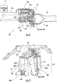
FIG. 1 is a perspective view of a wearable power module constructed in accordance with the present disclosure, showing a distributed energy storage system and a turboalternator supported by a harness; -
FIG. 2 is a longitudinal cross-sectional view of the turboalternator ofFIG. 1 , showing a turbine operatively connected to a permanent magnet generator and in fluid communication with the distributed energy system through a gas generator to generate electrical power; -
FIG. 3 is a perspective view of the distributed energy system ofFIG. 1 , showing a chemical energy source including fuel pressure vessels and compressed gas pressure vessels distributed and supported on a right-leg portion and a left-leg portion of the limb segment of the harness; -
FIG. 4 is a perspective view of the distributed energy system ofFIG. 1 , showing a ballistic shield enclosing compressed gas and fuel storage pressure vessels of the chemical energy source on a left-leg portion of the harness; -
FIG. 5 is a partial cross-sectional view of the distributed energy system ofFIG. 1 , showing a shear thickening fluid disposed between an inner case and an outer case of the ballistic shield, the shear-thickening fluid enveloping pressure vessels of the chemical energy source; and -
FIG. 6 is a perspective view of the distributed energy system ofFIG. 1 , showing a ballistic shield enclosing compressed gas and fuel storage pressure vessels of the chemical energy source and supported on the left-leg portion and the right-leg portion of the limb segment of the harness. - Reference will now be made to the drawings wherein like reference numerals identify similar structural features or aspects of the subject disclosure. For purposes of explanation and illustration, and not limitation, a partial view of an exemplary embodiment of an energy storage system constructed in accordance with the disclosure is shown in
FIG. 1 and is designated generally byreference character 100. Other embodiments of energy storage systems, wearable power modules, and exoskeletons having distributed energy systems in accordance with the present disclosure, or aspects thereof, are provided inFIGS. 2-6 , as will be described. The systems and methods described herein can be used for generating electrical power from a wearable power module, such as military applications, though the present disclosure is not limited to military applications or to wearable application in general. - Referring to
FIG. 1 , theenergy storage system 100 is shown. The distributed energy system is configured to provide chemical energy to aturboalternator 102 and includes aharness 104 and a chemical energy source 105 (shown inFIG. 3 ) with a plurality offuel pressure vessels 106 and a plurality of compressedgas pressure vessels 108. Theharness 104 includes atorso segment 110 and alimb segment 112. Thetorso segment 110 is configured and adapted to be worn by auser 10, e.g., a soldier, and has ashoulder portion 114 and alower back portion 116. Theshoulder portion 114 is configured to be suspended from the shoulders of theuser 10. Thelower back portion 116 is configured to be suspended from the lower back of theuser 10. As used herein the term fuel encompasses mono-propellants, which can provide a flow of high pressure decomposition products without an oxidizer, and liquid fuels requiring an oxidizer to generate high pressure combustion products. - The
limb segment 112 is configured and adapted to be worn by theuser 10 and has a right-leg portion 118 and a left-leg portion 120. The right-leg portion 118 is configured to be suspended from the right-leg of theuser 10. The left-leg portion 120 is configured to be suspended from the left-leg of theuser 10. In certain embodiments theharness 104 can be included in an exoskeleton 122 having a one or moresupport member element 124 and one or moreload transfer member 126 operably connected to the one ormore support member 124 to manipulate loads, e.g., themechanical load 12, according instructions received from theuser 10. - The
turboalternator 102 is supported by thetorso segment 110 of theharness 104. More specifically, the turboalternator is supported by thelower back portion 116 of thetorso segment 110 of theharness 104. Thefuel pressure vessels 106 and the compressedgas pressure vessels 108 are supported by thelimb segment 112 of theharness 104, and are each distributed on the limb segment of theharness 104. It is contemplated that one or more of thefuel pressure vessels 106 be supported by the right-leg portion 118 of theharness 104 and that one or more of thefuel pressure vessels 106 be supported by the left-leg portion 120 of theharness 104. It is also contemplated that one or more of the compressedgas pressure vessels 108 be supported by the right-leg portion 118 of theharness 104 and one or more of the compressedgas pressure vessels 108 be supported by the left-leg portion 120 of theharness 104. This allows theshoulder portion 114 of theharness 104 to be free such that amechanical load 12 may be positioned on theshoulder portion 114 of thetorso segment 110 of theharness 104. As shown inFIG. 1 themechanical load 12 includes a cargo pack 14, e.g., a rucksack-type military cargo pack, which is supported by theharness 104 above theturboalternator 102, thefuel pressure vessels 106, and the compressedgas pressure vessels 108. - With reference to
FIG. 2 , theturboalternator 102 is shown. Theturboalternator 102 is configured and adapted to convert chemical energy from the chemical energy source 105 (shown inFIG. 3 ) contained in one or more of the fuel pressure vessels 106 (shown inFIG. 1 ) into mechanical energy, and therefrom electrical energy for powering anelectrical load 16. In this respect theturboalternator 102 includes apower converter 128, apermanent magnet generator 130, and aninterconnect shaft 132. Theturboalternator 102 also includes a turbine 134, adiffuser 136, and agas generator 138. - The
gas generator 138 fluidly connects theenergy storage system 100 with the turbine 134, includes a decomposition orcombustion chamber 140, and is configured and adapted to generate a flow of highpressure combustion products 18 from afuel flow 20 provided to the decomposition orcombustion chamber 140 by theenergy storage system 100. The highpressure combustion products 18 are communicated to the turbine 134. As shown inFIG. 2 a mono-propellant is provided to a decomposition chamber and decomposed therein without utilization of an oxidizer to generate high pressure decomposition products. In certain embodiments a liquid fuel and an oxidizer, e.g., compressed air, can be provided to a combustion chamber and combusted therein to generate high pressure combustion products. - The turbine 134 fluidly connects the
gas generator 138 with theambient environment 22 and is operably connected to thepermanent magnet generator 130 by theinterconnect shaft 132. In this respect the turbine 134 receives the highpressure combustion products 18, expands the highpressure combustion products 18 as the highpressure combustion products 18 traverse the turbine 134, extracts work from the highpressure combustion products 18 as they traverse the turbine 134, and communicate the work to thepermanent magnet generator 130 as mechanical rotation R through theinterconnect shaft 132. Once expanded, the highpressure combustion products 18 are communicated to theambient environment 22 through thediffuser 136. Thediffuser 136 converts the remaining dynamic energy of the turbine exhaust into static pressure, which increases the available pressure ratio across the turbine 134 and turbine nozzles. In certain embodiments the turbine 134 includes animpulse turbine 140, providing radial compactness to the turbine 134. In accordance with certain embodiments the turbine 134 can include a single stage 142, providing axial compactness to the turbine 134. - The
permanent magnet generator 130 is operatively associated with the turbine 134, is electrically connected to thepower converter 128, and is configured and adapted to generate variable frequency alternating current (AC)power 24 using the mechanical rotation R provided to thepermanent magnet generator 130 by the turbine 134 through theinterconnect shaft 132. In this respect thepermanent magnet generator 130 includes one or morepermanent magnet 144, fixed in rotation relative to theinterconnect shaft 132, and supported for rotation relative to a stator winding 146. Thepermanent magnet 144 generates magnetic flux, which is communicated to the stator winding 146 during rotation and which induces a flow of alternating current in the stator winding 146. - The
power converter 128 electrically connects the stator winding 146 with theelectrical load 16 and is configured and adapted to convert the variablefrequency AC power 24 provided by thepermanent magnet generator 130 into direct current (DC)power 32. Conversion is accomplished by a rectifier circuit 148, which in certain embodiments is arectifier circuit 150. In certain embodiments therectifier circuit 150 includes a diode bridge, which passively rectifies the variablefrequency AC power 24 intoDC power 32 with a relatively simple circuit arrangement. - With reference to
FIG. 3 , a portion of theenergy storage system 100 is shown. The energy storage system includes thefuel pressure vessels 106 and the compressedgas pressure vessels 108. A first compressedgas pressure vessel 108A, a firstfuel pressure vessel 106A, and one or more secondfuel pressure vessel 106B are supported by the right-leg portion 118 of thelimb segment 112 of theharness 104. The first compressedgas pressure vessel 108A contains a compressedgas charge 34. In certain embodiments the compressedgas charge 34 includes an inert gas, such as substantially pure nitrogen by way of non-limiting example. The firstfuel pressure vessel 106A and the one or more secondfuel pressure vessel 106B respectively contain afuel charge 36. In certain embodiment thefuel charge 36 is a liquid fuel charge, such as a kerosene-based liquid fuel like JP-8 in conjunction with an oxidizer in a combustion chamber by way of non-limiting example. - The first
fuel pressure vessel 106A and the one or more secondfuel pressure vessel 106B are in fluid communication with theturboalternator 102. More specifically, the firstfuel pressure vessel 106A is connected to theturboalternator 102 in parallel with the one or more secondfuel pressure vessel 106B. In this respect athrottle valve 152 fluidly connects the firstfuel pressure vessel 106A and the one or more secondfuel pressure vessel 106B to theturboalternator 102, thethrottle valve 152 controlling the speed of the turbine 134 by throttling the rate of the flow of thefuel charge 36 to the turbine 134. It is contemplated that the compressedgas charge 34 from the compressedgas pressure vessel 108 drive fuel from theliquid fuel charge 36 to theturboalternator 102. In certain embodiments theenergy storage system 100 provides a liquid fuel 38 to theturboalternator 102. - The first compressed
gas pressure vessel 108A is fluidly coupled to theturboalternator 102 by the firstfuel pressure vessel 106A and the one or more secondfuel pressure vessel 106B, respectively, in a blowdown arrangement. In this respect the first compressedgas pressure vessel 108A is fluidly connected to the firstfuel pressure vessel 106A and the one or more secondfuel pressure vessel 106B at the right-leg portion 118 to pressurize the fuel contained in both the firstfuel pressure vessel 106A and the one or more secondfuel pressure vessel 106B. As will be appreciated by those of skill in the art in view of the present disclosure, pressurizing thefuel charge 36 within the firstfuel pressure vessel 106A and the one or more secondfuel pressure vessel 106B using the compressedgas charge 34 within the first compressedgas pressure vessel 108A simplifies the control scheme for delivery of fuel to theturboalternator 102, the turbinespeed control valve 152 employing a variable orifice structure in certain embodiments. - The second compressed
gas pressure vessel 108B is similar to the first compressedgas pressure vessel 108A, and is additionally supported on the left-leg portion 120 of thelimb segment 112 of theharness 104. Further, the second compressedgas pressure vessel 108B is connected to theturboalternator 102 through both a thirdfuel pressure vessel 108C and one or more fourthfuel pressure vessel 108D. As will be appreciated by those of skill in the art in view of the present disclosure, this distributes fuel contained in theenergy storage system 100 both between the plurality offuel pressure vessels 106 supported on the left-leg portion 120 and the right-leg portion 118 of thelimb segment 112 of theharness 104. - With reference to
FIG. 4 , aballistic shield arrangement 160 is shown. Theballistic shield arrangement 160 is configured an adapted to provide ballistic protection and includes a left-leg ballistic shield 162 (shown inFIG. 5 ) and a right-legballistic shield 164. The right-legballistic shield 164 includes a fiber reinforcedceramic material 172. The fiber reinforcedceramic material 172 is configured and adapted to fragment an incoming projectile upon impact. Examples of suitable fiber-reinforced ceramic materials include those described inU.S. Patent No. 5,970,843 to Strasser et al., issued on October 26, 1999 , the contents of which are incorporated herein by reference in its entirety. - With reference to
FIG. 5 , the left-legballistic shield 162 and the right-legballistic shield 164 are shown. The left-legballistic shield 162 includes aninner case 166, anouter case 168, and ashear thickening fluid 170. Theinner case 166 is arranged between the firstfuel pressure vessel 106A and the left-leg portion 120 of theharness 104. More specifically, theinner case 166 is arranged between each of the firstfuel pressure vessel 106A, the one or more secondfuel pressure vessel 106B (shown inFIG. 1 ), and the first compressedgas pressure vessel 108A (shown inFIG. 1 ). - The
outer case 168 is arranged on a side of the firstfuel pressure vessel 106A opposite theinner case 166. More specifically, theouter case 168 is arranged on a side of the firstfuel pressure vessel 106A, the one or more secondfuel pressure vessel 106B, and the first compressedgas pressure vessel 108A opposite theinner case 166. Theshear thickening fluid 170 is disposed between theinner case 166 and theouter case 168. In this respect the shear thickening fluid 170 envelopes the firstfuel pressure vessel 106A, the one or more secondfuel pressure vessel 106B, and the first compressedgas pressure vessel 108A in a cavity defined between theouter case 168 and theinner case 166. Examples of suitable shear thickening fluids include ArmourGel®, available from the Dow Corning Company of Midland, Michigan. - As shown in
FIGS. 5 and6 , the left-legballistic shield 162 at least partially encloses the firstfuel pressure vessel 106A, the one or more secondfuel pressure vessel 106B, and the first compressedgas pressure vessel 108A. The right-legballistic shield 164 is similar to the left-legballistic shield 162, and additionally encloses thethird pressure vessel 106C, the one or morefourth pressure vessel 106D, and the second compressedgas pressure vessel 108B. - The term "about" is intended to include the degree of error associated with measurement of the particular quantity based upon the equipment available at the time of filing the application.
- The terminology used herein is for the purpose of describing particular embodiments only and is not intended to be limiting of the present disclosure. As used herein, the singular forms "a", "an" and "the" are intended to include the plural forms as well, unless the context clearly indicates otherwise. It will be further understood that the terms "comprises" and/or "comprising," when used in this specification, specify the presence of stated features, integers, steps, operations, elements, and/or components, but do not preclude the presence or addition of one or more other features, integers, steps, operations, element components, and/or groups thereof.
- While the present disclosure has been described with reference to an exemplary embodiment or embodiments, it will be understood by those skilled in the art that various changes may be made and equivalents may be substituted for elements thereof without departing from the scope of the present disclosure. In addition, many modifications may be made to adapt a particular situation or material to the teachings of the present disclosure without departing from the essential scope thereof. Therefore, it is intended that the present disclosure not be limited to the particular embodiment disclosed as the best mode contemplated for carrying out this present disclosure, but that the present disclosure will include all embodiments falling within the scope of the claims.
Claims (13)
- A wearable power module, comprising:
an energy storage system comprising:a harness (104) with a torso segment (110) and a limb segment (112);a turboalternator (102) supported by the torso segment of the harness; anda chemical energy source (105) in fluid communication with the turboalternator and supported by the harness, wherein the chemical energy source is supported on the limb segment of the harness in a distributed arrangement to allow for support of a mechanical load by the torso segment of the harness, wherein the chemical energy source comprises a first pressure vessel and one or more second pressure vessel, the one or more second pressure vessel in fluid communication with the turboalternator;wherein the limb segment of the harness includes a left-leg portion and a right-leg portion, wherein the first pressure vessel and the one or more second pressure vessel are distributed between the left-leg portion and right-leg portion of the limb segment; anda ballistic shield at least partially enclosing the first pressure vessel and the one or more second pressure vessel. - The wearable power module as recited in claim 1, wherein the torso segment of the harness has a shoulder portion and a lower back portion, wherein the turboalternator is supported by the lower back portion of the torso segment, and further comprising:a mechanical load including a cargo pack supported by the lower back portion of the harness; andan electrical load electrically connected to the turboalternator.
- The wearable power module as recited in claim 1 or 2, wherein the limb segment of the harness includes a left-leg portion and a right-leg portion, wherein the chemical energy source is distributed between the left-leg portion and right-leg portion of the limb segment.
- The wearable power module as recited in claim 1, 2 or 3, wherein the chemical energy source comprises a first pressure vessel and one or more second pressure vessel, the one or more second pressure vessel in fluid communication with the turboalternator.
- The wearable power module as recited in claim 4, wherein the first pressure vessel is fluidly connected to the turboalternator by the one or more second pressure vessel; and/orwherein the first pressure vessel contains a compressed gas charge, wherein the one or more second pressure vessel contains a fuel charge; and/orwherein the one or more second pressure vessel contains a liquid fuel charge, wherein the liquid fuel charge is pressurized by a compressed gas communicated by the first pressure vessel; and/orwherein limb segment of the harness comprises a left-leg portion and right-leg portion, wherein the first pressure vessel is supported by one of the left-leg portion and the right-leg portion, wherein the one or more second pressure vessel is supported by the other of left-leg portion and the right-leg portion.
- The wearable power module as recited in any preceding claim, further comprising a turbine speed control valve fluidly connecting the chemical energy source to the turboalternator.
- The wearable power module as recited in any preceding claim, wherein the torso segment of the harness has a shoulder portion and a lower back portion, wherein the turboalternator is supported by the lower back portion of the torso segment, and further comprising a mechanical load supported by the lower back portion of the harness.
- The wearable power module as recited in any preceding claim, further comprising an electrical load electrically connected to the turboalternator.
- The wearable power module as recited in any preceding claim, further comprising a ballistic shield at least partially enclosing the chemical energy source.
- The wearable power module as recited in claim 9, wherein the ballistic shield comprises an outer case, wherein the chemical energy source is arranged between the harness and the outer case of the ballistic shield.
- The wearable power module as recited in claim 9, wherein the ballistic shield comprises an inner case, wherein the inner case is arranged between the chemical energy source and the harness.
- The wearable power module as recited in in claim 9, wherein the ballistic shield comprises:an inner case arranged between the chemical energy source and the harness;an outer case arranged on a side of the chemical energy source opposite the inner case; anda shear thickening fluid disposed between the inner case and the outer case, the shear thickening fluid enveloping at least a portion of the chemical energy source; and/orwherein the ballistic shield comprises a fiber reinforced ceramic material; and/orwherein the chemical energy source comprises a first pressure vessel and one or more second pressure vessel, wherein the ballistic shield encloses the first pressure vessel and the one or more second pressure vessel.
- The wearable power module as recited in any preceding claim, wherein the turboalternator comprises:a power converter;a permanent magnet generator electrically connected to the power converter;a turbine operatively connected to the permanent magnet generator;a gas generator in fluid communication with the turbine; anda turbine speed control valve fluidly connecting the chemical energy source to the gas generator.
Applications Claiming Priority (1)
| Application Number | Priority Date | Filing Date | Title |
|---|---|---|---|
| US16/383,626 US10830562B2 (en) | 2019-04-14 | 2019-04-14 | Wearable power modules with distributed energy storage systems |
Publications (2)
| Publication Number | Publication Date |
|---|---|
| EP3725681A1 EP3725681A1 (en) | 2020-10-21 |
| EP3725681B1 true EP3725681B1 (en) | 2025-04-02 |
Family
ID=68886837
Family Applications (1)
| Application Number | Title | Priority Date | Filing Date |
|---|---|---|---|
| EP19215245.2A Active EP3725681B1 (en) | 2019-04-14 | 2019-12-11 | Wearable power modules with distributed energy storage systems |
Country Status (2)
| Country | Link |
|---|---|
| US (1) | US10830562B2 (en) |
| EP (1) | EP3725681B1 (en) |
Families Citing this family (2)
| Publication number | Priority date | Publication date | Assignee | Title |
|---|---|---|---|---|
| US12024285B1 (en) | 2022-03-10 | 2024-07-02 | Skypad Tech, Inc. | Modular mobility system including thrusters movably connected to a support structure |
| CN116317345A (en) * | 2023-03-03 | 2023-06-23 | 天津工业大学 | A wearable human upper limb motion energy harvester |
Citations (2)
| Publication number | Priority date | Publication date | Assignee | Title |
|---|---|---|---|---|
| US3023980A (en) * | 1958-10-13 | 1962-03-06 | Thompson Ramo Wooldridge Inc | Turbo-fan lift device |
| US20170151577A1 (en) * | 2015-12-01 | 2017-06-01 | Carlisle Fluid Technologies, Inc. | Spray tool power supply system and method |
Family Cites Families (39)
| Publication number | Priority date | Publication date | Assignee | Title |
|---|---|---|---|---|
| US3063663A (en) * | 1960-08-12 | 1962-11-13 | Weber Aircraft Corp | Artificial damping system |
| US3270986A (en) * | 1965-12-03 | 1966-09-06 | Harold I Johnson | Hand-held self-maneuvering unit |
| US3381917A (en) * | 1966-11-08 | 1968-05-07 | Bell Aerospace Corp | Personnel flying device |
| US3416753A (en) * | 1966-06-22 | 1968-12-17 | Bell Aerospace Corp | Autopilot for jet belt |
| USRE26756E (en) * | 1966-11-08 | 1970-01-06 | Personnel flying device | |
| US3556438A (en) * | 1969-09-02 | 1971-01-19 | Ludwig F Meditz | Airborne vehicle |
| US4281418A (en) * | 1978-02-07 | 1981-08-04 | Stanley Cieslak | Portable furnace for wearing apparel |
| US5970843A (en) | 1997-05-12 | 1999-10-26 | Northtrop Grumman Corporation | Fiber reinforced ceramic matrix composite armor |
| EP0950353A3 (en) * | 1998-04-15 | 2000-04-12 | Boral Energy Ltd. | Improvements in torches and burners for flame cultivation and flaming |
| US6062244A (en) * | 1998-08-13 | 2000-05-16 | Aci Medical | Fluidic connector |
| US6666796B1 (en) * | 1999-09-16 | 2003-12-23 | Aerovironment, Inc. | Walking assisting apparatus |
| US6938588B2 (en) * | 1999-11-12 | 2005-09-06 | Sarcos Investments, Lc | Controllable combustion method and device |
| GB2379957A (en) * | 2001-09-21 | 2003-03-26 | Qinetiq Ltd | Rankine cycle micropower unit |
| US6574950B2 (en) | 2001-10-01 | 2003-06-10 | Ingersoll-Rand Energy Systems Corporation | Thermally responsive recuperator housing |
| US20030066291A1 (en) * | 2001-10-05 | 2003-04-10 | Claudio Filippone | Internally powered compact actuator for robotic applications |
| US7047722B2 (en) * | 2002-10-02 | 2006-05-23 | Claudio Filippone | Small scale hybrid engine (SSHE) utilizing fossil fuels |
| WO2004082427A2 (en) * | 2003-03-17 | 2004-09-30 | Rome Lawrence C | A backpack for harvesting electrical energy during walking and for minimizing shoulder strain |
| JP4155081B2 (en) * | 2003-04-02 | 2008-09-24 | トヨタ自動車株式会社 | Vertical take-off and landing equipment |
| JP4096929B2 (en) * | 2004-08-19 | 2008-06-04 | トヨタ自動車株式会社 | Vertical take-off and landing aircraft |
| US20060196215A1 (en) * | 2004-12-08 | 2006-09-07 | Crumlin Ethan J | Environmentally adaptable transport device |
| US9182155B2 (en) * | 2004-12-08 | 2015-11-10 | Ethan J. Crumlin | Environmentally adaptable transport device |
| US20080034730A1 (en) * | 2005-12-28 | 2008-02-14 | Claudio Filippone | Small scale hybrid engine |
| US20090020654A1 (en) | 2007-06-08 | 2009-01-22 | Nelson Tyler | Harness with mounted engine frame |
| US20100230450A1 (en) * | 2009-03-13 | 2010-09-16 | Mario Tomberli | Outboard Motor Carrier |
| DE102009040494B4 (en) * | 2009-09-08 | 2019-09-05 | Andreas Stihl Ag & Co. Kg | Back-worn implement |
| CN102556348A (en) | 2010-12-23 | 2012-07-11 | 马世强 | Dynamic-suspension jet backpack |
| US8636247B2 (en) | 2011-04-19 | 2014-01-28 | Raytheon Company | Closed gas generator and micro power unit including the same |
| GB2502834A (en) * | 2012-06-08 | 2013-12-11 | Amir Golad | A generator assembly suitable for being carried on the back of a human |
| CA2883185A1 (en) * | 2012-08-27 | 2014-03-06 | Ekso Bionics, Inc. | Hydraulic actuator system |
| US9407125B2 (en) * | 2013-06-21 | 2016-08-02 | Queen's University At Kingston | Biomechanical electrical power generation apparatus |
| US9362803B2 (en) * | 2014-01-22 | 2016-06-07 | Constantinos G Panousis | Human powered generator |
| US10112713B2 (en) * | 2015-06-26 | 2018-10-30 | Nelson Tyler | Back mounted flight machine |
| US10245204B2 (en) * | 2015-09-11 | 2019-04-02 | Ekso Bionics, Inc. | Devices and methods for improving the utility of an exoskeleton mobility base |
| US20170105870A1 (en) * | 2015-10-14 | 2017-04-20 | Ataollah Yazdani | Fluid-based thermal clothing for heat exchange with body parts |
| GB2559971B (en) * | 2017-02-22 | 2019-03-13 | Gravity Ind Ltd | A wearable flight system with propulsion assemblies worn on a user's body |
| US10745129B2 (en) | 2017-04-27 | 2020-08-18 | Timothy J. NEAR | Multirotor vehicle |
| EP3621560A4 (en) * | 2017-05-12 | 2021-06-16 | Exonetik Inc. | EXOSKELETON, ORTHOSIS, DRESSING DEVICE OR MOBILE ROBOTS USING A MAGNETORHEOLOGICAL FLUID CLUTCH DEVICE |
| US10794271B2 (en) * | 2018-02-22 | 2020-10-06 | Rolls-Royce North American Technologies Inc. | Altitude augmentation system |
| US20200102894A1 (en) * | 2018-09-28 | 2020-04-02 | Rolls-Royce North American Technologies Inc. | Anti-surge and relight system |
-
2019
- 2019-04-14 US US16/383,626 patent/US10830562B2/en active Active
- 2019-12-11 EP EP19215245.2A patent/EP3725681B1/en active Active
Patent Citations (2)
| Publication number | Priority date | Publication date | Assignee | Title |
|---|---|---|---|---|
| US3023980A (en) * | 1958-10-13 | 1962-03-06 | Thompson Ramo Wooldridge Inc | Turbo-fan lift device |
| US20170151577A1 (en) * | 2015-12-01 | 2017-06-01 | Carlisle Fluid Technologies, Inc. | Spray tool power supply system and method |
Also Published As
| Publication number | Publication date |
|---|---|
| US20200326158A1 (en) | 2020-10-15 |
| US10830562B2 (en) | 2020-11-10 |
| EP3725681A1 (en) | 2020-10-21 |
Similar Documents
| Publication | Publication Date | Title |
|---|---|---|
| EP3725681B1 (en) | Wearable power modules with distributed energy storage systems | |
| EP2992199B1 (en) | A rotor assembly for an open cycle engine, and an open cycle engine | |
| US6457306B1 (en) | Electrical drive system for rocket engine propellant pumps | |
| US11732723B2 (en) | Power modules with regenerative compressor wheels | |
| JP2017534021A (en) | Exhaust section for aircraft gas turbine engines | |
| CN116588333A (en) | Automatic control flight knapsack device | |
| EP3736427B1 (en) | Power modules for hypersonic vehicles | |
| McNab | Electromagnetic augmentation can reduce space launch costs | |
| Toki et al. | On-orbit demonstration of a pulsed self-field magnetoplasmadynamic thruster system | |
| EP3726011A1 (en) | Power module with blow down fuel and propellant delivery system | |
| EP3726136B1 (en) | Distributed fuel modules with hydraulic flow circuit breakers and gaseous flow circuit breakers | |
| Huth et al. | Diesel Fuel-to-Electric Energy Conversion Using Compact, Portable, Stirling Engine-Based Systems | |
| Rauwolf et al. | Mission performance of emerging in-space propulsion concepts for one-year crewed Mars missions | |
| Hendrickson et al. | 160 W Dual Opposed Stirling Engine Power Source for Military Applications | |
| EP3672033A1 (en) | Combination of an electric generator and a turbopump | |
| US20050000212A1 (en) | Thermo-dynamic battery storage unit | |
| Meyer et al. | Electric auxiliary power unit for Shuttle evolution | |
| EP2398296B1 (en) | A fluid heating device and an engine comprising said device, in particular for a rocket | |
| Rothmund et al. | The early days of LOX/LH2 engines at SEP and MBB | |
| Chapman et al. | Vector controlled Stirling based power conversion approach for radioisotope powered missions | |
| Zimmerman | Advanced concept of an accessory power supply for guided missiles | |
| Koroteev et al. | Power-propulsion systems for orbital nuclear transfer | |
| Kramer et al. | Chemical rocket propulsion research and development in Germany | |
| HOBBS | The design of a general purpose modular propellant feed system | |
| Shinbrot | Secondary Power Generating System for a Manned Logistic Spacecraft |
Legal Events
| Date | Code | Title | Description |
|---|---|---|---|
| PUAI | Public reference made under article 153(3) epc to a published international application that has entered the european phase |
Free format text: ORIGINAL CODE: 0009012 |
|
| STAA | Information on the status of an ep patent application or granted ep patent |
Free format text: STATUS: THE APPLICATION HAS BEEN PUBLISHED |
|
| AK | Designated contracting states |
Kind code of ref document: A1 Designated state(s): AL AT BE BG CH CY CZ DE DK EE ES FI FR GB GR HR HU IE IS IT LI LT LU LV MC MK MT NL NO PL PT RO RS SE SI SK SM TR |
|
| AX | Request for extension of the european patent |
Extension state: BA ME |
|
| STAA | Information on the status of an ep patent application or granted ep patent |
Free format text: STATUS: REQUEST FOR EXAMINATION WAS MADE |
|
| 17P | Request for examination filed |
Effective date: 20210419 |
|
| RBV | Designated contracting states (corrected) |
Designated state(s): AL AT BE BG CH CY CZ DE DK EE ES FI FR GB GR HR HU IE IS IT LI LT LU LV MC MK MT NL NO PL PT RO RS SE SI SK SM TR |
|
| STAA | Information on the status of an ep patent application or granted ep patent |
Free format text: STATUS: EXAMINATION IS IN PROGRESS |
|
| 17Q | First examination report despatched |
Effective date: 20210910 |
|
| GRAP | Despatch of communication of intention to grant a patent |
Free format text: ORIGINAL CODE: EPIDOSNIGR1 |
|
| STAA | Information on the status of an ep patent application or granted ep patent |
Free format text: STATUS: GRANT OF PATENT IS INTENDED |
|
| INTG | Intention to grant announced |
Effective date: 20240315 |
|
| GRAS | Grant fee paid |
Free format text: ORIGINAL CODE: EPIDOSNIGR3 |
|
| GRAA | (expected) grant |
Free format text: ORIGINAL CODE: 0009210 |
|
| STAA | Information on the status of an ep patent application or granted ep patent |
Free format text: STATUS: THE PATENT HAS BEEN GRANTED |
|
| AK | Designated contracting states |
Kind code of ref document: B1 Designated state(s): AL AT BE BG CH CY CZ DE DK EE ES FI FR GB GR HR HU IE IS IT LI LT LU LV MC MK MT NL NO PL PT RO RS SE SI SK SM TR |
|
| REG | Reference to a national code |
Ref country code: GB Ref legal event code: FG4D |
|
| REG | Reference to a national code |
Ref country code: CH Ref legal event code: EP |
|
| REG | Reference to a national code |
Ref country code: IE Ref legal event code: FG4D |
|
| REG | Reference to a national code |
Ref country code: DE Ref legal event code: R096 Ref document number: 602019068030 Country of ref document: DE |
|
| REG | Reference to a national code |
Ref country code: NL Ref legal event code: MP Effective date: 20250402 |
|
| PG25 | Lapsed in a contracting state [announced via postgrant information from national office to epo] |
Ref country code: NL Free format text: LAPSE BECAUSE OF FAILURE TO SUBMIT A TRANSLATION OF THE DESCRIPTION OR TO PAY THE FEE WITHIN THE PRESCRIBED TIME-LIMIT Effective date: 20250402 |
|
| REG | Reference to a national code |
Ref country code: AT Ref legal event code: MK05 Ref document number: 1781095 Country of ref document: AT Kind code of ref document: T Effective date: 20250402 |
|
| PG25 | Lapsed in a contracting state [announced via postgrant information from national office to epo] |
Ref country code: PT Free format text: LAPSE BECAUSE OF FAILURE TO SUBMIT A TRANSLATION OF THE DESCRIPTION OR TO PAY THE FEE WITHIN THE PRESCRIBED TIME-LIMIT Effective date: 20250804 Ref country code: FI Free format text: LAPSE BECAUSE OF FAILURE TO SUBMIT A TRANSLATION OF THE DESCRIPTION OR TO PAY THE FEE WITHIN THE PRESCRIBED TIME-LIMIT Effective date: 20250402 Ref country code: ES Free format text: LAPSE BECAUSE OF FAILURE TO SUBMIT A TRANSLATION OF THE DESCRIPTION OR TO PAY THE FEE WITHIN THE PRESCRIBED TIME-LIMIT Effective date: 20250402 |
|
| REG | Reference to a national code |
Ref country code: LT Ref legal event code: MG9D |
|
| PG25 | Lapsed in a contracting state [announced via postgrant information from national office to epo] |
Ref country code: GR Free format text: LAPSE BECAUSE OF FAILURE TO SUBMIT A TRANSLATION OF THE DESCRIPTION OR TO PAY THE FEE WITHIN THE PRESCRIBED TIME-LIMIT Effective date: 20250703 Ref country code: NO Free format text: LAPSE BECAUSE OF FAILURE TO SUBMIT A TRANSLATION OF THE DESCRIPTION OR TO PAY THE FEE WITHIN THE PRESCRIBED TIME-LIMIT Effective date: 20250702 |
|
| PG25 | Lapsed in a contracting state [announced via postgrant information from national office to epo] |
Ref country code: PL Free format text: LAPSE BECAUSE OF FAILURE TO SUBMIT A TRANSLATION OF THE DESCRIPTION OR TO PAY THE FEE WITHIN THE PRESCRIBED TIME-LIMIT Effective date: 20250402 |
|
| PG25 | Lapsed in a contracting state [announced via postgrant information from national office to epo] |
Ref country code: BG Free format text: LAPSE BECAUSE OF FAILURE TO SUBMIT A TRANSLATION OF THE DESCRIPTION OR TO PAY THE FEE WITHIN THE PRESCRIBED TIME-LIMIT Effective date: 20250402 |
|
| PG25 | Lapsed in a contracting state [announced via postgrant information from national office to epo] |
Ref country code: HR Free format text: LAPSE BECAUSE OF FAILURE TO SUBMIT A TRANSLATION OF THE DESCRIPTION OR TO PAY THE FEE WITHIN THE PRESCRIBED TIME-LIMIT Effective date: 20250402 |
|
| PG25 | Lapsed in a contracting state [announced via postgrant information from national office to epo] |
Ref country code: AT Free format text: LAPSE BECAUSE OF FAILURE TO SUBMIT A TRANSLATION OF THE DESCRIPTION OR TO PAY THE FEE WITHIN THE PRESCRIBED TIME-LIMIT Effective date: 20250402 |
|
| PG25 | Lapsed in a contracting state [announced via postgrant information from national office to epo] |
Ref country code: RS Free format text: LAPSE BECAUSE OF FAILURE TO SUBMIT A TRANSLATION OF THE DESCRIPTION OR TO PAY THE FEE WITHIN THE PRESCRIBED TIME-LIMIT Effective date: 20250702 |
|
| PG25 | Lapsed in a contracting state [announced via postgrant information from national office to epo] |
Ref country code: IS Free format text: LAPSE BECAUSE OF FAILURE TO SUBMIT A TRANSLATION OF THE DESCRIPTION OR TO PAY THE FEE WITHIN THE PRESCRIBED TIME-LIMIT Effective date: 20250802 |
|
| PG25 | Lapsed in a contracting state [announced via postgrant information from national office to epo] |
Ref country code: LV Free format text: LAPSE BECAUSE OF FAILURE TO SUBMIT A TRANSLATION OF THE DESCRIPTION OR TO PAY THE FEE WITHIN THE PRESCRIBED TIME-LIMIT Effective date: 20250402 |
|
| REG | Reference to a national code |
Ref country code: DE Ref legal event code: R097 Ref document number: 602019068030 Country of ref document: DE |
|
| PGFP | Annual fee paid to national office [announced via postgrant information from national office to epo] |
Ref country code: DE Payment date: 20251126 Year of fee payment: 7 |
|
| PGFP | Annual fee paid to national office [announced via postgrant information from national office to epo] |
Ref country code: GB Payment date: 20251119 Year of fee payment: 7 |
|
| PG25 | Lapsed in a contracting state [announced via postgrant information from national office to epo] |
Ref country code: SM Free format text: LAPSE BECAUSE OF FAILURE TO SUBMIT A TRANSLATION OF THE DESCRIPTION OR TO PAY THE FEE WITHIN THE PRESCRIBED TIME-LIMIT Effective date: 20250402 Ref country code: DK Free format text: LAPSE BECAUSE OF FAILURE TO SUBMIT A TRANSLATION OF THE DESCRIPTION OR TO PAY THE FEE WITHIN THE PRESCRIBED TIME-LIMIT Effective date: 20250402 |
|
| PGFP | Annual fee paid to national office [announced via postgrant information from national office to epo] |
Ref country code: FR Payment date: 20251119 Year of fee payment: 7 |
|
| PG25 | Lapsed in a contracting state [announced via postgrant information from national office to epo] |
Ref country code: CZ Free format text: LAPSE BECAUSE OF FAILURE TO SUBMIT A TRANSLATION OF THE DESCRIPTION OR TO PAY THE FEE WITHIN THE PRESCRIBED TIME-LIMIT Effective date: 20250402 |
|
| PG25 | Lapsed in a contracting state [announced via postgrant information from national office to epo] |
Ref country code: EE Free format text: LAPSE BECAUSE OF FAILURE TO SUBMIT A TRANSLATION OF THE DESCRIPTION OR TO PAY THE FEE WITHIN THE PRESCRIBED TIME-LIMIT Effective date: 20250402 |
|
| PG25 | Lapsed in a contracting state [announced via postgrant information from national office to epo] |
Ref country code: SK Free format text: LAPSE BECAUSE OF FAILURE TO SUBMIT A TRANSLATION OF THE DESCRIPTION OR TO PAY THE FEE WITHIN THE PRESCRIBED TIME-LIMIT Effective date: 20250402 Ref country code: RO Free format text: LAPSE BECAUSE OF FAILURE TO SUBMIT A TRANSLATION OF THE DESCRIPTION OR TO PAY THE FEE WITHIN THE PRESCRIBED TIME-LIMIT Effective date: 20250402 |
|
| PG25 | Lapsed in a contracting state [announced via postgrant information from national office to epo] |
Ref country code: IT Free format text: LAPSE BECAUSE OF FAILURE TO SUBMIT A TRANSLATION OF THE DESCRIPTION OR TO PAY THE FEE WITHIN THE PRESCRIBED TIME-LIMIT Effective date: 20250402 |
|
| PLBE | No opposition filed within time limit |
Free format text: ORIGINAL CODE: 0009261 |
|
| STAA | Information on the status of an ep patent application or granted ep patent |
Free format text: STATUS: NO OPPOSITION FILED WITHIN TIME LIMIT |
|
| REG | Reference to a national code |
Ref country code: CH Ref legal event code: L10 Free format text: ST27 STATUS EVENT CODE: U-0-0-L10-L00 (AS PROVIDED BY THE NATIONAL OFFICE) Effective date: 20260211 |
|
| 26N | No opposition filed |
Effective date: 20260105 |