EP3725638A1 - Collision energy absorption structure and rail vehicle having same - Google Patents
Collision energy absorption structure and rail vehicle having same Download PDFInfo
- Publication number
- EP3725638A1 EP3725638A1 EP18932821.4A EP18932821A EP3725638A1 EP 3725638 A1 EP3725638 A1 EP 3725638A1 EP 18932821 A EP18932821 A EP 18932821A EP 3725638 A1 EP3725638 A1 EP 3725638A1
- Authority
- EP
- European Patent Office
- Prior art keywords
- energy absorption
- absorption structure
- collision
- tube
- bottom plate
- Prior art date
- Legal status (The legal status is an assumption and is not a legal conclusion. Google has not performed a legal analysis and makes no representation as to the accuracy of the status listed.)
- Granted
Links
Images


Classifications
-
- B—PERFORMING OPERATIONS; TRANSPORTING
- B61—RAILWAYS
- B61F—RAIL VEHICLE SUSPENSIONS, e.g. UNDERFRAMES, BOGIES OR ARRANGEMENTS OF WHEEL AXLES; RAIL VEHICLES FOR USE ON TRACKS OF DIFFERENT WIDTH; PREVENTING DERAILING OF RAIL VEHICLES; WHEEL GUARDS, OBSTRUCTION REMOVERS OR THE LIKE FOR RAIL VEHICLES
- B61F19/00—Wheel guards; Bumpers; Obstruction removers or the like
- B61F19/04—Bumpers or like collision guards
-
- B—PERFORMING OPERATIONS; TRANSPORTING
- B61—RAILWAYS
- B61D—BODY DETAILS OR KINDS OF RAILWAY VEHICLES
- B61D17/00—Construction details of vehicle bodies
- B61D17/04—Construction details of vehicle bodies with bodies of metal; with composite, e.g. metal and wood body structures
- B61D17/06—End walls
-
- B—PERFORMING OPERATIONS; TRANSPORTING
- B61—RAILWAYS
- B61F—RAIL VEHICLE SUSPENSIONS, e.g. UNDERFRAMES, BOGIES OR ARRANGEMENTS OF WHEEL AXLES; RAIL VEHICLES FOR USE ON TRACKS OF DIFFERENT WIDTH; PREVENTING DERAILING OF RAIL VEHICLES; WHEEL GUARDS, OBSTRUCTION REMOVERS OR THE LIKE FOR RAIL VEHICLES
- B61F1/00—Underframes
-
- B—PERFORMING OPERATIONS; TRANSPORTING
- B61—RAILWAYS
- B61F—RAIL VEHICLE SUSPENSIONS, e.g. UNDERFRAMES, BOGIES OR ARRANGEMENTS OF WHEEL AXLES; RAIL VEHICLES FOR USE ON TRACKS OF DIFFERENT WIDTH; PREVENTING DERAILING OF RAIL VEHICLES; WHEEL GUARDS, OBSTRUCTION REMOVERS OR THE LIKE FOR RAIL VEHICLES
- B61F1/00—Underframes
- B61F1/08—Details
- B61F1/10—End constructions
-
- Y—GENERAL TAGGING OF NEW TECHNOLOGICAL DEVELOPMENTS; GENERAL TAGGING OF CROSS-SECTIONAL TECHNOLOGIES SPANNING OVER SEVERAL SECTIONS OF THE IPC; TECHNICAL SUBJECTS COVERED BY FORMER USPC CROSS-REFERENCE ART COLLECTIONS [XRACs] AND DIGESTS
- Y02—TECHNOLOGIES OR APPLICATIONS FOR MITIGATION OR ADAPTATION AGAINST CLIMATE CHANGE
- Y02T—CLIMATE CHANGE MITIGATION TECHNOLOGIES RELATED TO TRANSPORTATION
- Y02T30/00—Transportation of goods or passengers via railways, e.g. energy recovery or reducing air resistance
Definitions
- the present invention relates to the technical field of rail vehicles, and in particular to a collision energy absorption structure and a rail vehicle having the same.
- the present invention provides a collision energy absorption structure and a rail vehicle having the same, intended to solve the problem in the conventional art in which a collision energy absorption structure of an energy absorption member of a rail vehicle cannot meet requirements of complex road conditions.
- the present invention provides a collision energy absorption structure.
- the collision energy absorption structure includes: a primary energy absorption structure, connected to a chassis boundary beam of a vehicle, the primary energy absorption structure having at least two spaced energy absorption cavities; an end energy absorption structure, the lower end of the end energy absorption structure being connected to the primary energy absorption structure; and a roof structure, the upper end of the end energy absorption structure being connected to the roof structure.
- the primary energy absorption structure comprises an end beam, two ends of the end beam are connected to a chassis boundary beam of the vehicle respectively, the end beam has an end beam bottom plate and an end beam vertical plate connected to the end beam bottom plate, and the end beam vertical plate is vertically disposed and defines the energy absorption cavity on the end beam bottom plate.
- the end energy absorption structure comprises a first energy absorption cylinder
- the middle of the end beam bottom plate is provided with a first cylinder mounting hole a
- the first energy absorption cylinder penetrates into the first cylinder mounting hole a and is welded to the end beam bottom plate.
- the end beam bottom plate comprises a first bottom plate and a second bottom plate disposed oppositely, and the first energy absorption cylinder is welded to the first bottom plate and the second bottom plate respectively.
- the end energy absorption structure further comprises a second energy absorption cylinder, having a first end welded to the roof structure and a second end welded to the primary energy absorption structure.
- first energy absorption cylinders there are two second energy absorption cylinders, the two second energy absorption cylinders being spaced; and there are two first energy absorption cylinders, the two first energy absorption cylinders being spaced, and the two first energy absorption cylinders being located between the two second energy absorption cylinders.
- two ends of the end beam bottom plate are separately provided with a second cylinder mounting hole, and the second energy absorption cylinder penetrates into the second cylinder mounting hole and is welded to the end beam bottom plate.
- the collision energy absorption structure further comprises a secondary energy absorption structure, the secondary energy absorption structure being connected to the primary energy absorption structure, the secondary energy absorption structure comprising at least two spaced energy absorption tubes and the primary energy absorption structure being connected to a first end of the energy absorption tube.
- the energy absorption tube is a hollow structure, the energy absorption tube is provided with a first induction portion.
- the first induction portion comprises an induction hole, and the induction hole is a through hole.
- the cross section of the energy absorption tube is rectangular
- the first induction portion comprises at least one group of induction holes
- the induction holes of each group is spaced in the circumferential direction of the energy absorption tube along a plane vertical to the axis of the energy absorption tube.
- the first induction portion comprises a plurality of groups of induction holes, the plurality of groups of induction holes being spaced along an extending direction of the energy absorption tube.
- the energy absorption tube comprises at least two adjacent side walls, the two adjacent side walls are connected to form a bending portion, and the first induction portion is disposed on at least one bending portion of the energy absorption tube.
- the energy absorption tube is also provided with a second induction portion, the second induction portion being disposed on a side wall of the energy absorption tube.
- the second induction portion is depressed into the side wall of the energy absorption tube to form a depression portion.
- the cross section of the energy absorption tube is rectangular, there are two second induction portions, and the two second induction portions are disposed on the side walls of the energy absorption tube oppositely.
- the collision energy absorption structure comprising a tertiary energy absorption structure, wherein the tertiary energy absorption structure is connected to a second end of the energy absorption tube.
- the tertiary energy absorption structure comprises a stopping beam, and two ends of the stopping beam are connected to the chassis boundary beam of the rail vehicle respectively.
- the second end of the energy absorption tube is connected to the stopping beam.
- the stopping beam comprises a first stopping segment, a second stopping segment and a third stopping segment connected in sequence, the second end of the energy absorption tube is welded to the second stopping segment, a first included angle is provided between the first stopping segment and the second stopping segment, the first included angle is an obtuse angle, a second included angle is provided between the third stopping segment and the second stopping segment, and the first included angle is equal to the second included angle.
- first stopping segment is provided with a plurality of spaced second weight-reducing holes; and/or, the third stopping segment is provided with a plurality of spaced third weight-reducing holes.
- a rail vehicle includes a collision energy absorption structure, wherein the collision energy absorption structure is the collision energy absorption structure according to any one of the above contents.
- a primary energy absorption structure on an end chassis, a roof structure, and an end energy absorption structure mounted between the roof structure and the primary energy absorption structure form an end integrated energy absorption structure of a vehicle body structure, and an independent energy absorption structure element is no longer needed.
- the present invention improves the collision energy absorption performance of a vehicle without increasing the external dimension of the vehicle body structure. Since the external dimension of the vehicle is not increased, the collision energy absorption structure of the present invention can meet the technical requirements of small gap between vehicle end couplings and small curve negotiation and can meet more requirements of complex road conditions.
- an embodiment of the present invention provides a collision energy absorption structure.
- the collision energy absorption structure mainly includes: a primary energy absorption structure 10, connected to a chassis boundary beam 40 of a vehicle, the primary energy absorption structure 10 having at least two spaced energy absorption cavities; an end energy absorption structure 80, the lower end of the end energy absorption structure 80 being connected to the primary energy absorption structure 10; and a roof structure 90, the upper end of the end energy absorption structure 80 being connected to the roof structure 90.
- the primary energy absorption structure 10 on an end chassis, the roof structure 90 and the end energy absorption structure 80 mounted between the roof structure 90 and the primary energy absorption structure 10 form an end integrated energy absorption structure of a vehicle body structure, and an independent energy absorption structure element is no longer needed.
- the present invention improves the collision energy absorption performance of a vehicle without increasing the external dimension of the vehicle body structure, and meets the requirements for collision energy absorption of a vehicle body structure.
- the external dimension of the vehicle body structure does not need to be changed, the dimension of the vehicle can be consistent with the existing vehicle, so that the requirements for a vehicle compatible with couplings can be met, and the compatibility of the vehicle is improved. Since the external dimension of the vehicle is not increased, the collision energy absorption structure of the present invention can meet the technical requirements of small gap between vehicle end couplings and small curve negotiation and can adapt to more complex road conditions.
- the primary energy absorption structure 10 includes an end beam 11, two ends of the end beam 11 are connected to the chassis boundary beam 40 of the vehicle respectively, the end beam 11 has an end beam bottom plate 111 and an end beam vertical plate 112 connected to the end beam bottom plate 111, and the end beam vertical plate 112 is vertically disposed and defines the energy absorption cavity on the end beam bottom plate 111.
- the end beam vertical plate 112 is vertically disposed on the end beam bottom plate 111, so that the primary energy absorption structure 10 naturally forms an energy absorption cavity having an energy absorption effect, thus improving the collision performance of the rail vehicle, and guaranteeing the personal safety of people in the vehicle.
- the primary energy absorption structure 10 when the primary energy absorption structure 10 is subjected to a collision pressure in a direction reverse to the running direction of the rail vehicle, the energy absorption cavity is deformed by the pressure to absorb the collision extrusion force, thus guaranteeing the personal safety of people in the vehicle.
- the end beam bottom plate 111 includes a first bottom plate and a second bottom plate disposed oppositely.
- the end beam vertical plate 112 is vertically disposed and is connected to the end beam bottom plate 111, so as to define the energy absorption cavity on the end beam bottom plate 111.
- the end beam vertical plate 112 is vertically disposed on the first bottom plate, and defines the energy absorption cavity on the first bottom plate.
- the second bottom plate covers the end beam vertical plate 112. That is, the end beam vertical plate 112 is vertically disposed under the second bottom plate, and defines the energy absorption cavity under the second bottom plate. That is, the energy absorption cavity is surrounded by the end beam vertical plate 112 and the end beam bottom plate 111.
- the first bottom plate and the second bottom plate included by the end beam bottom plate 111 are disposed above and below the energy absorption cavity respectively.
- the end beam vertical plate 112 includes a first edge vertical plate 112a, a second edge vertical plate 112b and multiple middle vertical plates 112c, wherein the first edge vertical plate 112a and the second edge vertical plate 112b are spaced, two ends of the vertical plates 112c are connected to the first edge vertical plate 112a and the second edge vertical plate 112b respectively, the multiple middle vertical plates 112c are spaced, and multiple spaced energy absorption cavities are defined between the first edge vertical plate 112a and the second edge vertical plate 112b.
- the design of forming multiple energy absorption cavities by the first edge vertical plate 112a, the second edge vertical plate 112b and the multiple middle vertical plates 112c enables the primary energy absorption structure 10 to have multiple energy absorption cavities provided along the vehicle width direction of the rail vehicle, so that when being subjected to a collision extrusion force, the end beam vertical plate 112 forming multiple energy absorption cavities is inclined and deformed into the energy absorption cavities, so as to absorb collision energy.
- the middle vertical plate 112c and the first edge vertical plate 112a spaced by the multiple energy absorption cavities are subjected to a collision extrusion force, a support force is provided against the collision extrusion force, and finally, the middle vertical plate 112c and the first edge vertical plate 112a are deformed to absorb the energy of the collision extrusion force.
- the first edge vertical plate 112a is connected to the tail end of one end of the chassis boundary beam 40, and the first edge vertical plate 112a is an arc-shaped structure.
- the collision energy absorption structure is used for improving the collision performance of a vehicle end. Therefore, the collision energy absorption structure may be disposed at any one end of a rail vehicle, that is, the collision energy absorption structure may be disposed at a first end of the rail vehicle or the collision energy absorption structure may be disposed at a second end of the rail vehicle or the collision energy absorption structure may be symmetrically disposed at the first end and the second end of the rail vehicle as shown in Fig. 1 .
- the scenario in which the first edge vertical plate 112a is connected to the tail end of one end of the chassis boundary beam 40 includes that: the first vertical plate may be connected to the tail end of the first end of the chassis boundary beam 40, or the first vertical plate may be connected to the tail end of the second end of the chassis boundary beam 40, or the first vertical plate may be connected to the tail ends of the first end and the second end of the chassis boundary beam 40.
- the first edge vertical plate 112a is disposed at a chassis end, and a first layer of vertical plate protection is formed at the chassis end. Secondly, the first edge vertical plate 112a is connected to the tail end of the chassis boundary beam 40 and connected to one end of multiple middle vertical plates 112c, thus ensuring that the first edge vertical plate 112a can disperse the collision extrusion force to the multiple middle vertical plates 112c and the chassis boundary beam 40 when the end of the rail vehicle is collided and extruded, so that the situation that the primary energy absorption structure 10 cannot steadily absorb energy due to over-concentrated applying point of the collision extrusion force is prevented.
- first edge vertical plate 112a is an arc-shaped structure, which has the technical effect of enhancing dispersion of the collision extrusion force.
- first edge vertical plate 112a is designed as an arc-shaped structure, so that multiple connected rail vehicles may be prevented from colliding each other while turning.
- a side, away from the energy absorption cavity, of the first edge vertical plate 112a may be connected with an anti-creeping tooth 101, so that the collision energy absorption structure achieves an anti-creeping effect as well. That is, when two rail vehicles collide each other, the height and tooth number of the anti-creeping teeth 101 of the two vehicles are consistent, so that when the collision occurs, the end beam 11 ensures engagement of at least one anti-creeping tooth 101, and the vehicles will not mismatch in the height direction.
- the first edge vertical plate 112a, the second edge vertical plate 112b, the multiple middle vertical plates 112c and the end beam bottom plate 111 included in the primary energy absorption structure 10 are welded to each other.
- the first edge vertical plate 112a, the second edge vertical plate 112b and the chassis boundary beam 40 are also welded.
- the primary energy absorption structure 10 may also be adjusted in various manners.
- at least one middle vertical plate 112c in the multiple middle vertical plates 112c is provided with a first weight-reducing hole, wherein the first weight-reducing hole is used for reducing the weight of the rail vehicle or the collision energy absorption structure.
- the middle of the end beam bottom plate 111 is provided with a vehicle hook mounting hole 111b connected to a vehicle hook of the rail vehicle.
- the multiple middle vertical plates 112c include: two first middle vertical plates 112c, two second middle vertical plates 112c and two third middle vertical plates 112c, wherein the two first middle vertical plates 112c, the two second middle vertical plates 112c and the two third middle vertical plates 112c are symmetrically disposed along the vehicle width direction of the rail vehicle, a first energy absorption cavity is formed between the two first middle vertical plates 112c, a first bottom plate corresponding to the first energy absorption cavity is provided with a vehicle hook mounting hole 111b, a second energy absorption cavity is formed between the first middle vertical plate 112c and the second middle vertical plate 112c, the end beam bottom plate 111 corresponding to the second energy absorption cavity is provided with a first cylinder mounting hole 111a, a third energy absorption cavity is formed between the second middle vertical plate 112c and the third middle vertical plate 112c, and a fourth energy absorption cavity is formed between the third energy absorption cavity and the chassis boundary beam 40.
- first middle vertical plate 112c is parallel to the third middle vertical plate 112c
- both the first middle vertical plate 112c and the third middle vertical plate 112c are vertical to the second middle vertical plate 112c
- a preset angle is provided between the first middle vertical plate 112c and the second middle vertical plate 112c.
- both the first middle vertical plate 112c and the second middle vertical plate 112c are provided with first weight-reducing holes.
- the end energy absorption structure 80 is further described.
- the end energy absorption structure 80 includes a first energy absorption cylinder 81, the middle of the end beam bottom plate 111 is provided with a first cylinder mounting hole 111a, and the first energy absorption cylinder 81 penetrates into the first cylinder mounting hole 111 a and is welded to the end beam bottom plate 111.
- This design of providing the first cylinder mounting hole 111a in the middle of the end beam bottom plate 111 enables the first energy absorption cylinder 81 to penetrate through the first cylinder mounting hole 111a to be welded to the end beam bottom plate 111, and enhances the connecting strength between the end energy absorption cylinder and the end beam 11, thus improving the connecting strength of an end skeleton of the rail vehicle, and protecting the personal safety of a passenger.
- the end beam bottom plate 111 includes a first bottom plate and a second bottom plate, the middle of the first bottom plate is provided with a third cylinder mounting hole, the middle of the second bottom plate is provided with a fourth cylinder mounting hole, and the first energy absorption cylinder penetrates through the third cylinder mounting hole and the fourth cylinder mounting hole and is welded to the first bottom plate and the second bottom plate respectively.
- This design not only enables the first bottom plate and the second bottom plate to be welded to the first energy absorption cylinder, but also increases the connecting stability of the vehicle end skeleton.
- the degree of inclining the first energy absorption cylinder into a carriage may be limited, so as to protect the personal safety of a passenger.
- the first cylinder mounting hole 111a includes a third cylinder mounting hole and a fourth cylinder mounting hole.
- the end energy absorption structure 80 further includes a second energy absorption cylinder 82, having a first end welded to the roof structure 90 and a second end welded to the primary energy absorption structure 10.
- two second energy absorption cylinders 82 are designed, the two second energy absorption cylinders 82 are spaced, and the second energy absorption cylinders 82 are welded to a side wall 70 of the rail vehicle.
- the above design enhances the connecting strength between the roof structure 90 of the rail vehicle and the chassis of the rail vehicle, and the design of welding the second energy absorption cylinders 82 to the side wall 70 of the rail vehicle improves the integrity of the vehicle end skeleton structure, so that when the vehicle end skeleton structure is collided and extruded, more components of the rail vehicle provide an anti-collision support.
- the design of spacing two energy absorption cylinders improves the balance of a connecting relationship between the roof structure 90 and the chassis structure, and avoids the distortion and deformation of the vehicle end skeleton structure at a weak part of the connecting relationship caused by the unbalanced connecting relationship between the roof structure 90 and the chassis structure.
- the two second energy absorption cylinders 82 there are two second energy absorption cylinders 82, the two second energy absorption cylinders 82 are spaced, there are two first energy absorption cylinders 81, and the two first energy absorption cylinders 81 are located between the two second energy absorption cylinders 82.
- the example is obtained based on statistic analysis of a great number of experimental data.
- the number and position of the first energy absorption cylinder 81 in the example and the number and position of the second energy absorption cylinder 82 in the example are stably balanced, that is, a balance between the weight and connecting strength of the end energy absorption structure 80 is achieved, and a balance between the position design and connecting stability of the end energy absorption structure 80 is achieved.
- two ends of the end beam bottom plate 111 are separately provided with a second cylinder mounting hole 111c, and the second energy absorption cylinder 82 penetrates into the second cylinder mounting hole 111c and is welded to the end beam bottom plate 111.
- This design of providing the second cylinder mounting hole 111c in the middle of the end beam bottom plate 111 enables the second energy absorption cylinder 82 to penetrate through the second cylinder mounting hole 111c to be welded to the end beam bottom plate 111, and enhances the connecting strength between the second cylinder mounting hole 111c and the end beam bottom plate 111, thus improving the connecting strength of an end skeleton of the rail vehicle, and protecting the personal safety of a passenger.
- the first energy absorption cylinder 81 is a collision cylinder
- the second energy absorption cylinder 82 is an end corner post.
- the collision cylinder and the end corner post form a protection structure of a vehicle front end, so as to protect the life safety of a crew member and a passenger in the vehicle.
- the four cylinders are of a closed tubular structure, and the size of the section needs to meet the requirements.
- the collision cylinder and the end corner post form an integrated structure with a roof bending beam on a roof and the end beam 11 at the vehicle front end.
- the side wall 70 of the remaining vehicle body and the roof structure 90 are welded together to form a whole.
- the collision energy absorption structure further includes a secondary energy absorption structure 20, the secondary energy absorption structure 20 being connected to the primary energy absorption structure 10, the secondary energy absorption structure 20 including at least two spaced energy absorption tubes 21, and the primary energy absorption structure 10 being connected to a first end of the energy absorption tube 21.
- the secondary energy absorption structure 20 is then described.
- This design of providing the energy absorption cavity of the primary energy absorption structure 10 and the energy absorption tube 21 of the secondary energy absorption structure 20 at the end of the rail vehicle at least forms double energy absorption guarantee for the end of the rail vehicle. That is, at least two spaced energy absorption cavities of the primary energy absorption structure 10 and the energy absorption tube 21 of the secondary energy absorption structure 20 may absorb a certain collision energy to cause energy absorption deformation, thus improving the collision performance of the rail vehicle, and ensuring the personal safety of a passenger.
- each stage of energy absorption structure will be deformed stage by stage, so that the deformation of the energy absorption structure is within a controllable range, thus avoiding from affecting the safety of people in the vehicle due to non-controllable deformation caused by the train structure.
- the energy absorption tube 21 is set as a hollow structure, and the energy absorption tube 21 is provided with a first induction portion 213.
- the structure of the energy absorption tube is simple, and since the first induction portion 213 is provided, the part, in the first induction portion 213, of the energy absorption tube 21 is first deformed when the collision occurs, so that the deformation of the energy absorption tube 21 is in a controllable state, thus avoiding from threatening the personal safety of people in the vehicle due to non-controllable deformation of other parts of a rail train. Therefore, the present invention improves the anti-collision performance of the collision energy absorption structure.
- the energy absorption tube 21 is symmetrically disposed along the vehicle width direction, and the energy absorption tube 21 is a thin-wall tube provided with an induction hole 211, thus facilitating deformation control of the energy absorption tube 21.
- the energy absorption tube 21 is connected to the second edge vertical plate 112b and a cross beam of a traction beam 50 in a welding manner.
- the energy absorption tube 21 includes a first tube body portion 214 and a second tube body portion 215, the first tube body portion 214 and the second tube body portion 215 being spliced.
- the two tube body portions are spliced to form the energy absorption tube 21 having a cavity, and during processing, the first tube body portion 214 and the second tube body portion 215 are spliced and welded at the spliced part.
- This structural form is simple in structure, and facilitates modular design, so that the cost can be reduced, and the processing efficiency is improved.
- the first tube body portion 214 is a U-shaped structure
- the first tube body portion 214 includes a first bottom wall and two first side walls
- the second tube body portion 215 is a U-shaped structure
- the second tube body portion 215 includes a second bottom wall and two second side walls
- the two first side walls are butted with the two second side walls respectively.
- the first tube body portion 214 and the second tube body portion 215 are U-shaped structures and are symmetrically disposed.
- the two side walls of the first tube body portion 214 and the second tube body portion 215 are butted in a one-to-one correspondence manner.
- Such design forms a flat plane at a to-be-welded part, facilitates the welding process, and improves the production efficiency.
- the first tube body portion 214 and the second tube body portion 215, which are symmetrically disposed, have the same structure, thereby facilitating batch production, and reducing the cost.
- the energy absorption tube 21 includes at least two adjacent side walls, the two adjacent side walls are connected to form a bending portion, and the first induction portion 213 is disposed on at least one bending portion of the energy absorption tube 21.
- the bending portion of the energy absorption tube 21 is provided with the first induction portion 213 to form a collision induction structure.
- the first induction portion 213 is disposed at the bending part, which is easy to process, so that the production efficiency can be improved.
- the cross section of the energy absorption tube 21 in the present embodiment is rectangular, the rectangular energy absorption tube 21 has a good torsional property, and the safety of the collision energy absorption structure can be further improved.
- the first induction portion 213 includes an induction hole 211, the induction hole 211 being a through hole.
- the induction hole 211 is a through hole, which is easy to process.
- the first induction portion 213 includes at least one group of induction holes 211, and each group of induction holes 211 is spaced in the circumferential direction of the energy absorption tube 21 along a plane vertical to the axis of the energy absorption tube 21.
- Multiple induction holes 211 are spaced on the energy absorption tube 21 along each plane vertical to the axis of the energy absorption tube 21, and the multiple induction holes 211 are uniformly distributed along the circumferential direction of the energy absorption tube 21.
- the induction holes 211 uniformly distributed in the circumferential direction of the energy absorption tube 21 make the energy absorption tube 21 folded basically along a plane, so that the deformation is more controllable.
- the first induction portion 213 includes multiple groups of induction holes 211, the multiple groups of induction holes 211 being spaced along an extending direction of the energy absorption tube 21.
- the multiple groups of induction holes 211 are spaced on the energy absorption tube 21. When the collision occurs, deformation is performed once at each group of induction holes 211. By providing the multiple groups of induction holes 211, the energy absorption tube 21 may be deformed repeatedly, thus improving the energy absorption capability of the energy absorption tube 21.
- the energy absorption tube 21 is further provided with a second induction portion 216, the second induction portion 216 being disposed on the side wall of the energy absorption tube 21.
- the second induction portion 216 is depressed into the side wall of the energy absorption tube 21 to form a depression portion 212.
- the axes of the first induction portion 213 and the second induction portion 216 are on the same plane vertical to the extending direction of the energy absorption tube 21.
- the provision of the second induction portion 216 facilitates the formation of a weaker induction part at this part, so that this part may be deformed prior to other parts.
- the cross section of the energy absorption tube 21 is rectangular, there are two second induction portions 216, and the two second induction portions 216 are disposed on the side wall of the energy absorption tube 21 oppositely.
- the first tube body portion 214 is a U-shaped structure, and the first tube body portion 214 includes a first bottom wall and two first side walls.
- the second tube body portion 215 is a U-shaped structure, and the second tube body portion 215 includes a second bottom wall and two second side walls.
- the two first side walls are butted with the two second side walls respectively, and the second induction portion 216 is disposed on the first bottom wall and the second bottom wall respectively.
- the second induction portion 216 is a groove depressed into the energy absorption tube 21, the bottom wall of the groove is parallel to the side wall of the energy absorption tube 21, and the side wall of the groove is an inclined surface, and the cross section of the groove is trapezoidal.
- the collision energy absorption structure further includes a tertiary energy absorption structure 30.
- the tertiary energy absorption structure 30 is described hereinafter.
- the tertiary energy absorption structure 30 is connected to the second end of the energy absorption tube 21.
- the tertiary energy absorption structure 30 includes a stopping beam 31, two ends of the stopping beam 31 are connected to the chassis boundary beam 40 of the rail vehicle respectively, and the second end of the energy absorption tube 21 is connected to the stopping beam 31.
- Such design increases the connecting strength of the energy absorption tube 21. That is, the energy absorption tube 21 forms an indirect connecting relationship with the chassis boundary beam 40 through the stopping beam, thereby avoiding the situation that controllable deformation cannot be performed due to unbalanced stress caused by the position offset of the energy absorption tube 21 when being collided.
- this design also increases the collision performance of the rail vehicle. That is, when the rail vehicle is collided, the stopping beam can provide a support against the collision, so as to reduce the degree of deformation of the rail vehicle. Further, the stopping beam is subjected to energy absorption deformation to absorb certain collision energy.
- the stopping beam 31 is a cross beam having a U-shaped section. This design makes the stopping beam unlikely to deform, that is, the stopping beam 31 having the U-shaped section may bear a larger collision force without deformation. It is to be noted that the direction of the collision force may be the running direction of the rail vehicle, or may be the vehicle width direction of the rail vehicle.
- the stopping beam 31 includes a first stopping segment, a second stopping segment and a third stopping segment connected in sequence, the second end of the energy absorption tube 21 is welded to the second stopping segment, a first included angle is provided between the first stopping segment and the second stopping segment, the first included angle is an obtuse angle, a second included angle is provided between the third stopping segment and the second stopping segment, and the first included angle is equal to the second included angle.
- the stopping beam includes a fourth stopping segment, a fifth stopping segment and a sixth stopping segment connected in sequence, and the second end of the energy absorption tube 21 is welded to the second stopping segment.
- the length of the side surface of the fourth stopping segment is the same as the length of the side surface of the sixth stopping segment, the length of the side surface of the fifth stopping segment is smaller than the length of the side surface of the stopping segment, and the length of the side surface of the stopping beam is based on the running direction of the rail vehicle.
- the other surface of the second stopping segment is also welded to first ends of two traction beams 50, and second ends of the two traction beams 50 are welded to a sleeper beam 60, wherein a vehicle hook mounting seat 51 is also disposed between the two traction beams 50, the stopping beam and the sleeper beam 60.
- the tertiary energy absorption structure 30 may also be adjusted in various manners.
- the first stopping segment is provided with multiple spaced second weight-reducing holes, wherein the second weight-reducing holes are used for reducing the weight of the rail vehicle or the collision energy absorption structure.
- the third stopping segment is provided with multiple spaced third weight-reducing holes, wherein the third weight-reducing holes are used for reducing the weight of the rail vehicle or the collision energy absorption structure.
- the outer contour of the tertiary energy absorption structure 30 may be changed as required.
- the stopping beam 31 is lengthened, and the stopping beam 31 is widened.
- the rail vehicle includes a collision energy absorption structure, wherein the collision energy absorption structure is the above collision energy absorption structure.
- the collision energy absorption structure of the solution is not only an energy absorption member, but also a load carrying structure.
- the primary energy absorption structure 10 on an end chassis, the roof structure 90 and the end energy absorption structure 80 mounted between the roof structure 90 and the primary energy absorption structure 10 form an end integrated energy absorption structure of a vehicle body structure, and an independent energy absorption structure element is no longer needed.
- the present invention improves the collision energy absorption performance of a vehicle without increasing the external dimension of the vehicle body structure, and meets the requirements for collision energy absorption of a vehicle body structure.
- the external dimension of the vehicle body structure does not need to be changed, the dimension of the vehicle can be consistent with the existing vehicle, so that the requirements for a vehicle compatible with couplings can be met, and the compatibility of the vehicle is improved. Since the external dimension of the vehicle is not increased, the collision energy absorption structure of the present invention can meet the technical requirements of small gap between vehicle end couplings and small curve negotiation and can adapt to more complex road conditions.
- locative or positional relations indicated by “front, back, up, down, left, and right”, “horizontal, vertical, perpendicular, and horizontal”, “top and bottom” and other terms are locative or positional relations shown on the basis of the drawings, which are only intended to make it convenient to describe the present invention and to simplify the descriptions without indicating or impliedly indicating that the referring device or element must have a specific location and must be constructed and operated with the specific location, and accordingly it cannot be understood as limitations to the present invention.
- the nouns of locality “inner and outer” refer to the inner and outer contours of each component.
- spatial relative terms such as “over”, “above”, “on an upper surface” and “upper” may be used herein for describing a spatial position relation between a device or feature and other devices or features shown in the drawings. It will be appreciated that the spatial relative terms aim to contain different orientations in usage or operation besides the orientations of the devices described in the drawings. For example, if the devices in the drawings are inverted, devices described as “above other devices or structures” or “over other devices or structures” will be located as “below other devices or structures” or “under other devices or structures”. Thus, an exemplar term “above” may include two orientations namely “above” and “below”. The device may be located in other different modes (rotated by 90 degrees or located in other orientations), and spatial relative descriptions used herein are correspondingly explained.
Landscapes
- Engineering & Computer Science (AREA)
- Mechanical Engineering (AREA)
- Life Sciences & Earth Sciences (AREA)
- Wood Science & Technology (AREA)
- Body Structure For Vehicles (AREA)
- Vibration Dampers (AREA)
Abstract
Description
- The present invention relates to the technical field of rail vehicles, and in particular to a collision energy absorption structure and a rail vehicle having the same.
- With the high-speed development of the fields of rail transits, the running safety issues have been valued by people increasingly while making travel convenient. Rail transit vehicles such as a subway are usually large in passenger capacity and high in running speed, and once a collision accident happens, serious personnel casualties and property losses will be caused. Recent train rear-ended accidents fully show that train collision accidents cannot be completely avoided even through a series of measures are taken in terms of signal control, scheduling management and programming management. In this case, the performance of a passive safety protection device serving as an ultimate guardian for passenger life and property safety is particularly important.
- Statistics show that rail transit vehicles need to absorb a large energy in the collision process, and therefore the collision performance of an energy absorption member of a rail vehicle is an important indicator for quality measurement. With the continuous acceleration of rail transit vehicles, the collision performance of the energy absorption member is highly required. The collision performance of the energy absorption member of the rail vehicle cannot meet current demands in the related art.
- In addition, under some special working conditions, vehicle end couplings are required to have a small gap and allow a small curve negotiation. Under these requirements, once the collision energy absorption requirement for the vehicle is improved, a collision energy absorption structure design for the vehicle needs to be added, the size of the energy absorption structure needs to be increased to increase the size of a vehicle end, and therefore it is difficult to meet the demand of a small curve negotiation. A technical solution for solving the complex road conditions has not been found yet for this case.
- The present invention provides a collision energy absorption structure and a rail vehicle having the same, intended to solve the problem in the conventional art in which a collision energy absorption structure of an energy absorption member of a rail vehicle cannot meet requirements of complex road conditions.
- In order to solve the above problem, according to an aspect of the present invention, the present invention provides a collision energy absorption structure. The collision energy absorption structure includes: a primary energy absorption structure, connected to a chassis boundary beam of a vehicle, the primary energy absorption structure having at least two spaced energy absorption cavities; an end energy absorption structure, the lower end of the end energy absorption structure being connected to the primary energy absorption structure; and a roof structure, the upper end of the end energy absorption structure being connected to the roof structure.
- Further, the primary energy absorption structure comprises an end beam, two ends of the end beam are connected to a chassis boundary beam of the vehicle respectively, the end beam has an end beam bottom plate and an end beam vertical plate connected to the end beam bottom plate, and the end beam vertical plate is vertically disposed and defines the energy absorption cavity on the end beam bottom plate.
- Further, the end energy absorption structure comprises a first energy absorption cylinder, the middle of the end beam bottom plate is provided with a first cylinder mounting hole a, and the first energy absorption cylinder penetrates into the first cylinder mounting hole a and is welded to the end beam bottom plate.
- Further, the end beam bottom plate comprises a first bottom plate and a second bottom plate disposed oppositely, and the first energy absorption cylinder is welded to the first bottom plate and the second bottom plate respectively.
- Further, the end energy absorption structure further comprises a second energy absorption cylinder, having a first end welded to the roof structure and a second end welded to the primary energy absorption structure.
- Further, there are two second energy absorption cylinders, the two second energy absorption cylinders being spaced; and there are two first energy absorption cylinders, the two first energy absorption cylinders being spaced, and the two first energy absorption cylinders being located between the two second energy absorption cylinders.
- Further, two ends of the end beam bottom plate are separately provided with a second cylinder mounting hole, and the second energy absorption cylinder penetrates into the second cylinder mounting hole and is welded to the end beam bottom plate.
- Further, the collision energy absorption structure further comprises a secondary energy absorption structure, the secondary energy absorption structure being connected to the primary energy absorption structure, the secondary energy absorption structure comprising at least two spaced energy absorption tubes and the primary energy absorption structure being connected to a first end of the energy absorption tube.
- Further, the energy absorption tube is a hollow structure, the energy absorption tube is provided with a first induction portion.
- Further, the first induction portion comprises an induction hole, and the induction hole is a through hole.
- Further, the cross section of the energy absorption tube is rectangular, the first induction portion comprises at least one group of induction holes, and the induction holes of each group is spaced in the circumferential direction of the energy absorption tube along a plane vertical to the axis of the energy absorption tube.
- Further, the first induction portion comprises a plurality of groups of induction holes, the plurality of groups of induction holes being spaced along an extending direction of the energy absorption tube.
- Further, the energy absorption tube comprises at least two adjacent side walls, the two adjacent side walls are connected to form a bending portion, and the first induction portion is disposed on at least one bending portion of the energy absorption tube.
- Further, the energy absorption tube is also provided with a second induction portion, the second induction portion being disposed on a side wall of the energy absorption tube.
- Further, the second induction portion is depressed into the side wall of the energy absorption tube to form a depression portion.
- Further, the cross section of the energy absorption tube is rectangular, there are two second induction portions, and the two second induction portions are disposed on the side walls of the energy absorption tube oppositely.
- Further, the collision energy absorption structure comprising a tertiary energy absorption structure, wherein the tertiary energy absorption structure is connected to a second end of the energy absorption tube.
- Further, the tertiary energy absorption structure comprises a stopping beam, and two ends of the stopping beam are connected to the chassis boundary beam of the rail vehicle respectively.
- Further, the second end of the energy absorption tube is connected to the stopping beam.
- Further, the stopping beam comprises a first stopping segment, a second stopping segment and a third stopping segment connected in sequence, the second end of the energy absorption tube is welded to the second stopping segment, a first included angle is provided between the first stopping segment and the second stopping segment, the first included angle is an obtuse angle, a second included angle is provided between the third stopping segment and the second stopping segment, and the first included angle is equal to the second included angle.
- Further, the first stopping segment is provided with a plurality of spaced second weight-reducing holes; and/or, the third stopping segment is provided with a plurality of spaced third weight-reducing holes.
- According to another aspect of the present invention, a rail vehicle is provided. The rail vehicle includes a collision energy absorption structure, wherein the collision energy absorption structure is the collision energy absorption structure according to any one of the above contents.
- According to the technical solution of the present invention, a primary energy absorption structure on an end chassis, a roof structure, and an end energy absorption structure mounted between the roof structure and the primary energy absorption structure form an end integrated energy absorption structure of a vehicle body structure, and an independent energy absorption structure element is no longer needed. The present invention improves the collision energy absorption performance of a vehicle without increasing the external dimension of the vehicle body structure. Since the external dimension of the vehicle is not increased, the collision energy absorption structure of the present invention can meet the technical requirements of small gap between vehicle end couplings and small curve negotiation and can meet more requirements of complex road conditions.
- The accompanying drawings, which constitute a part of this application, are used to provide a further understanding of the present invention, and the exemplary embodiments of the present invention and the description thereof are used to explain the present invention, but do not constitute improper limitations to the present invention. In the drawings:
-
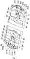
Fig. 1 illustrates a first structure diagram of a collision energy absorption structure according to the present invention; -
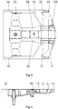
Fig. 2 illustrates a top view of a first end of a collision energy absorption structure according to the present invention; -
Fig. 3 illustrates a side view of a first end of a collision energy absorption structure according to the present invention; -
Fig. 4 illustrates a top view of a second end of a collision energy absorption structure according to the present invention; -
Fig. 5 illustrates a side view of a second end of a collision energy absorption structure according to the present invention; -
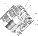
Fig. 6 illustrates a second structure diagram of a collision energy absorption structure according to the present invention; -
Fig. 7 illustrates a stereogram of an energy absorption tube of a collision energy absorption structure according to the present invention; -
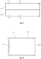
Fig. 8 illustrates a front view of an energy absorption tube of a collision energy absorption structure according to the present invention; -
Fig. 9 illustrates a top view of an energy absorption tube of a collision energy absorption structure according to the present invention; and -
Fig. 10 illustrates a sectional view of an energy absorption tube of a collision energy absorption structure according to the present invention. - The drawings include the following reference signs:
- 10: primary energy absorption structure; 11: end beam; 111: end beam bottom plate; 112: end beam vertical plate; 111a: first cylinder mounting hole; 111b: vehicle hook mounting hole; 111c: second cylinder mounting hole; 112a: first edge vertical plate; 112b: second edge vertical plate; 112c: middle vertical plate; 101: anti-creeping tooth;
- 20: secondary energy absorption structure; 21: energy absorption tube; 211: induction hole; 212: depression portion; 213: first induction portion; 214: first tube body portion; 215: second tube body portion; 216: second induction portion;
- 30: tertiary energy absorption structure; 31: stopping beam;
- 40: chassis boundary beam;
- 50: traction beam; 51: vehicle hook mounting seat;
- 60: sleeper beam;
- 70: side wall;
- 80: end energy absorption structure; 81: first energy absorption cylinder; 82: second energy absorption cylinder;
- 90: roof structure.
- The technical solutions in the embodiments of the present invention will be clearly and completely described herein below with the drawings in the embodiments of the present invention. It is apparent that the described embodiments are only part of the embodiments of the present invention, not all of the embodiments. The following description of at least one exemplary embodiment is only illustrative actually, and is not used as any limitation for the present invention and the application or use thereof. On the basis of the embodiments of the present invention, all other embodiments obtained on the premise of no creative work of those of ordinary skill in the art fall within the scope of protection of the present invention.
- As shown in
Fig. 1 to Fig. 9 , an embodiment of the present invention provides a collision energy absorption structure. The collision energy absorption structure mainly includes: a primaryenergy absorption structure 10, connected to achassis boundary beam 40 of a vehicle, the primaryenergy absorption structure 10 having at least two spaced energy absorption cavities; an end energy absorption structure 80, the lower end of the end energy absorption structure 80 being connected to the primaryenergy absorption structure 10; and aroof structure 90, the upper end of the end energy absorption structure 80 being connected to theroof structure 90. - In the present invention, the primary
energy absorption structure 10 on an end chassis, theroof structure 90 and the end energy absorption structure 80 mounted between theroof structure 90 and the primaryenergy absorption structure 10 form an end integrated energy absorption structure of a vehicle body structure, and an independent energy absorption structure element is no longer needed. The present invention improves the collision energy absorption performance of a vehicle without increasing the external dimension of the vehicle body structure, and meets the requirements for collision energy absorption of a vehicle body structure. In addition, since the external dimension of the vehicle body structure does not need to be changed, the dimension of the vehicle can be consistent with the existing vehicle, so that the requirements for a vehicle compatible with couplings can be met, and the compatibility of the vehicle is improved. Since the external dimension of the vehicle is not increased, the collision energy absorption structure of the present invention can meet the technical requirements of small gap between vehicle end couplings and small curve negotiation and can adapt to more complex road conditions. - Firstly, the primary
energy absorption structure 10 of the collision energy absorption structure is described. - According to an embodiment of the present invention, as shown in
Fig. 1 , the primaryenergy absorption structure 10 includes anend beam 11, two ends of theend beam 11 are connected to thechassis boundary beam 40 of the vehicle respectively, theend beam 11 has an end beambottom plate 111 and an end beamvertical plate 112 connected to the end beambottom plate 111, and the end beamvertical plate 112 is vertically disposed and defines the energy absorption cavity on the end beambottom plate 111. The end beamvertical plate 112 is vertically disposed on the end beambottom plate 111, so that the primaryenergy absorption structure 10 naturally forms an energy absorption cavity having an energy absorption effect, thus improving the collision performance of the rail vehicle, and guaranteeing the personal safety of people in the vehicle. That is, when the primaryenergy absorption structure 10 is subjected to a collision pressure in a direction reverse to the running direction of the rail vehicle, the energy absorption cavity is deformed by the pressure to absorb the collision extrusion force, thus guaranteeing the personal safety of people in the vehicle. - It is to be noted that the end beam
bottom plate 111 includes a first bottom plate and a second bottom plate disposed oppositely. The end beamvertical plate 112 is vertically disposed and is connected to the end beambottom plate 111, so as to define the energy absorption cavity on the end beambottom plate 111. Specifically, the end beamvertical plate 112 is vertically disposed on the first bottom plate, and defines the energy absorption cavity on the first bottom plate. In addition, the second bottom plate covers the end beamvertical plate 112. That is, the end beamvertical plate 112 is vertically disposed under the second bottom plate, and defines the energy absorption cavity under the second bottom plate. That is, the energy absorption cavity is surrounded by the end beamvertical plate 112 and the end beambottom plate 111. In the present embodiment, the first bottom plate and the second bottom plate included by the end beambottom plate 111 are disposed above and below the energy absorption cavity respectively. - For the above energy absorption cavity, in the present embodiment, specifically as shown in
Fig. 1 , the end beamvertical plate 112 includes a first edgevertical plate 112a, a second edgevertical plate 112b and multiple middlevertical plates 112c, wherein the first edgevertical plate 112a and the second edgevertical plate 112b are spaced, two ends of thevertical plates 112c are connected to the first edgevertical plate 112a and the second edgevertical plate 112b respectively, the multiple middlevertical plates 112c are spaced, and multiple spaced energy absorption cavities are defined between the first edgevertical plate 112a and the second edgevertical plate 112b. The design of forming multiple energy absorption cavities by the first edgevertical plate 112a, the second edgevertical plate 112b and the multiple middlevertical plates 112c enables the primaryenergy absorption structure 10 to have multiple energy absorption cavities provided along the vehicle width direction of the rail vehicle, so that when being subjected to a collision extrusion force, the end beamvertical plate 112 forming multiple energy absorption cavities is inclined and deformed into the energy absorption cavities, so as to absorb collision energy. Specifically speaking, when the middlevertical plate 112c and the first edgevertical plate 112a spaced by the multiple energy absorption cavities are subjected to a collision extrusion force, a support force is provided against the collision extrusion force, and finally, the middlevertical plate 112c and the first edgevertical plate 112a are deformed to absorb the energy of the collision extrusion force. - For the above first edge
vertical plate 112a, in the present embodiment, specifically as shown inFig. 1 , the first edgevertical plate 112a is connected to the tail end of one end of thechassis boundary beam 40, and the first edgevertical plate 112a is an arc-shaped structure. - It is to be noted that in the present embodiment, the collision energy absorption structure is used for improving the collision performance of a vehicle end. Therefore, the collision energy absorption structure may be disposed at any one end of a rail vehicle, that is, the collision energy absorption structure may be disposed at a first end of the rail vehicle or the collision energy absorption structure may be disposed at a second end of the rail vehicle or the collision energy absorption structure may be symmetrically disposed at the first end and the second end of the rail vehicle as shown in
Fig. 1 . - From the above description, it can be seen that the scenario in which the first edge
vertical plate 112a is connected to the tail end of one end of thechassis boundary beam 40 includes that: the first vertical plate may be connected to the tail end of the first end of thechassis boundary beam 40, or the first vertical plate may be connected to the tail end of the second end of thechassis boundary beam 40, or the first vertical plate may be connected to the tail ends of the first end and the second end of thechassis boundary beam 40. - The first edge
vertical plate 112a is disposed at a chassis end, and a first layer of vertical plate protection is formed at the chassis end. Secondly, the first edgevertical plate 112a is connected to the tail end of thechassis boundary beam 40 and connected to one end of multiple middlevertical plates 112c, thus ensuring that the first edgevertical plate 112a can disperse the collision extrusion force to the multiple middlevertical plates 112c and thechassis boundary beam 40 when the end of the rail vehicle is collided and extruded, so that the situation that the primaryenergy absorption structure 10 cannot steadily absorb energy due to over-concentrated applying point of the collision extrusion force is prevented. - In addition, the first edge
vertical plate 112a is an arc-shaped structure, which has the technical effect of enhancing dispersion of the collision extrusion force. In addition, the first edgevertical plate 112a is designed as an arc-shaped structure, so that multiple connected rail vehicles may be prevented from colliding each other while turning. - In the present embodiment, a side, away from the energy absorption cavity, of the first edge
vertical plate 112a may be connected with ananti-creeping tooth 101, so that the collision energy absorption structure achieves an anti-creeping effect as well. That is, when two rail vehicles collide each other, the height and tooth number of theanti-creeping teeth 101 of the two vehicles are consistent, so that when the collision occurs, theend beam 11 ensures engagement of at least oneanti-creeping tooth 101, and the vehicles will not mismatch in the height direction. - It is to be noted that in order to ensure the connecting stability of the primary
energy absorption structure 10 and ensure the collision performance of the primaryenergy absorption structure 10, the first edgevertical plate 112a, the second edgevertical plate 112b, the multiple middlevertical plates 112c and the end beambottom plate 111 included in the primaryenergy absorption structure 10 are welded to each other. In addition, the first edgevertical plate 112a, the second edgevertical plate 112b and thechassis boundary beam 40 are also welded. - The primary
energy absorption structure 10 may also be adjusted in various manners. As an optional example, at least one middlevertical plate 112c in the multiple middlevertical plates 112c is provided with a first weight-reducing hole, wherein the first weight-reducing hole is used for reducing the weight of the rail vehicle or the collision energy absorption structure. - As another optional example, the middle of the end beam
bottom plate 111 is provided with a vehiclehook mounting hole 111b connected to a vehicle hook of the rail vehicle. - As an optional example, as shown in
Fig. 1 , the multiple middlevertical plates 112c include: two first middlevertical plates 112c, two second middlevertical plates 112c and two third middlevertical plates 112c, wherein the two first middlevertical plates 112c, the two second middlevertical plates 112c and the two third middlevertical plates 112c are symmetrically disposed along the vehicle width direction of the rail vehicle, a first energy absorption cavity is formed between the two first middlevertical plates 112c, a first bottom plate corresponding to the first energy absorption cavity is provided with a vehiclehook mounting hole 111b, a second energy absorption cavity is formed between the first middlevertical plate 112c and the second middlevertical plate 112c, the end beambottom plate 111 corresponding to the second energy absorption cavity is provided with a firstcylinder mounting hole 111a, a third energy absorption cavity is formed between the second middlevertical plate 112c and the third middlevertical plate 112c, and a fourth energy absorption cavity is formed between the third energy absorption cavity and thechassis boundary beam 40. In addition, the first middlevertical plate 112c is parallel to the third middlevertical plate 112c, both the first middlevertical plate 112c and the third middlevertical plate 112c are vertical to the second middlevertical plate 112c, and a preset angle is provided between the first middlevertical plate 112c and the second middlevertical plate 112c. In addition, both the first middlevertical plate 112c and the second middlevertical plate 112c are provided with first weight-reducing holes. - The end energy absorption structure 80 is further described.
- As shown in
Fig. 6 , in the present embodiment, the end energy absorption structure 80 includes a firstenergy absorption cylinder 81, the middle of the end beambottom plate 111 is provided with a firstcylinder mounting hole 111a, and the firstenergy absorption cylinder 81 penetrates into the firstcylinder mounting hole 111 a and is welded to the end beambottom plate 111. This design of providing the firstcylinder mounting hole 111a in the middle of the end beambottom plate 111 enables the firstenergy absorption cylinder 81 to penetrate through the firstcylinder mounting hole 111a to be welded to the end beambottom plate 111, and enhances the connecting strength between the end energy absorption cylinder and theend beam 11, thus improving the connecting strength of an end skeleton of the rail vehicle, and protecting the personal safety of a passenger. - As an optional example, the end beam
bottom plate 111 includes a first bottom plate and a second bottom plate, the middle of the first bottom plate is provided with a third cylinder mounting hole, the middle of the second bottom plate is provided with a fourth cylinder mounting hole, and the first energy absorption cylinder penetrates through the third cylinder mounting hole and the fourth cylinder mounting hole and is welded to the first bottom plate and the second bottom plate respectively. This design not only enables the first bottom plate and the second bottom plate to be welded to the first energy absorption cylinder, but also increases the connecting stability of the vehicle end skeleton. Moreover, since a certain height difference is provided between the first bottom plate and the second bottom plate, the degree of inclining the first energy absorption cylinder into a carriage may be limited, so as to protect the personal safety of a passenger. It is to be noted that the firstcylinder mounting hole 111a includes a third cylinder mounting hole and a fourth cylinder mounting hole. - As shown in
Fig. 6 , the end energy absorption structure 80 further includes a secondenergy absorption cylinder 82, having a first end welded to theroof structure 90 and a second end welded to the primaryenergy absorption structure 10. - In an embodiment of the present invention, two second
energy absorption cylinders 82 are designed, the two secondenergy absorption cylinders 82 are spaced, and the secondenergy absorption cylinders 82 are welded to aside wall 70 of the rail vehicle. The above design enhances the connecting strength between theroof structure 90 of the rail vehicle and the chassis of the rail vehicle, and the design of welding the secondenergy absorption cylinders 82 to theside wall 70 of the rail vehicle improves the integrity of the vehicle end skeleton structure, so that when the vehicle end skeleton structure is collided and extruded, more components of the rail vehicle provide an anti-collision support. The design of spacing two energy absorption cylinders improves the balance of a connecting relationship between theroof structure 90 and the chassis structure, and avoids the distortion and deformation of the vehicle end skeleton structure at a weak part of the connecting relationship caused by the unbalanced connecting relationship between theroof structure 90 and the chassis structure. - As another optional example, as shown in
Fig. 6 , there are two secondenergy absorption cylinders 82, the two secondenergy absorption cylinders 82 are spaced, there are two firstenergy absorption cylinders 81, and the two firstenergy absorption cylinders 81 are located between the two secondenergy absorption cylinders 82. The example is obtained based on statistic analysis of a great number of experimental data. The number and position of the firstenergy absorption cylinder 81 in the example and the number and position of the secondenergy absorption cylinder 82 in the example are stably balanced, that is, a balance between the weight and connecting strength of the end energy absorption structure 80 is achieved, and a balance between the position design and connecting stability of the end energy absorption structure 80 is achieved. - Preferably, two ends of the end beam
bottom plate 111 are separately provided with a second cylinder mounting hole 111c, and the secondenergy absorption cylinder 82 penetrates into the second cylinder mounting hole 111c and is welded to the end beambottom plate 111. This design of providing the second cylinder mounting hole 111c in the middle of the end beambottom plate 111 enables the secondenergy absorption cylinder 82 to penetrate through the second cylinder mounting hole 111c to be welded to the end beambottom plate 111, and enhances the connecting strength between the second cylinder mounting hole 111c and the end beambottom plate 111, thus improving the connecting strength of an end skeleton of the rail vehicle, and protecting the personal safety of a passenger. - In an example, the first
energy absorption cylinder 81 is a collision cylinder, and the secondenergy absorption cylinder 82 is an end corner post. The collision cylinder and the end corner post form a protection structure of a vehicle front end, so as to protect the life safety of a crew member and a passenger in the vehicle. The four cylinders are of a closed tubular structure, and the size of the section needs to meet the requirements. The collision cylinder and the end corner post form an integrated structure with a roof bending beam on a roof and theend beam 11 at the vehicle front end. Theside wall 70 of the remaining vehicle body and theroof structure 90 are welded together to form a whole. - Then, the collision energy absorption structure further includes a secondary
energy absorption structure 20, the secondaryenergy absorption structure 20 being connected to the primaryenergy absorption structure 10, the secondaryenergy absorption structure 20 including at least two spacedenergy absorption tubes 21, and the primaryenergy absorption structure 10 being connected to a first end of theenergy absorption tube 21. The secondaryenergy absorption structure 20 is then described. - This design of providing the energy absorption cavity of the primary
energy absorption structure 10 and theenergy absorption tube 21 of the secondaryenergy absorption structure 20 at the end of the rail vehicle at least forms double energy absorption guarantee for the end of the rail vehicle. That is, at least two spaced energy absorption cavities of the primaryenergy absorption structure 10 and theenergy absorption tube 21 of the secondaryenergy absorption structure 20 may absorb a certain collision energy to cause energy absorption deformation, thus improving the collision performance of the rail vehicle, and ensuring the personal safety of a passenger. In addition, if the vehicle is collided, since the energy absorption structure is disposed stage by stage, each stage of energy absorption structure will be deformed stage by stage, so that the deformation of the energy absorption structure is within a controllable range, thus avoiding from affecting the safety of people in the vehicle due to non-controllable deformation caused by the train structure. - The
energy absorption tube 21 is set as a hollow structure, and theenergy absorption tube 21 is provided with afirst induction portion 213. The structure of the energy absorption tube is simple, and since thefirst induction portion 213 is provided, the part, in thefirst induction portion 213, of theenergy absorption tube 21 is first deformed when the collision occurs, so that the deformation of theenergy absorption tube 21 is in a controllable state, thus avoiding from threatening the personal safety of people in the vehicle due to non-controllable deformation of other parts of a rail train. Therefore, the present invention improves the anti-collision performance of the collision energy absorption structure. Preferably, theenergy absorption tube 21 is symmetrically disposed along the vehicle width direction, and theenergy absorption tube 21 is a thin-wall tube provided with aninduction hole 211, thus facilitating deformation control of theenergy absorption tube 21. Theenergy absorption tube 21 is connected to the second edgevertical plate 112b and a cross beam of atraction beam 50 in a welding manner. - According to an embodiment of the present invention, as shown in
Fig. 7 , theenergy absorption tube 21 includes a firsttube body portion 214 and a secondtube body portion 215, the firsttube body portion 214 and the secondtube body portion 215 being spliced. The two tube body portions are spliced to form theenergy absorption tube 21 having a cavity, and during processing, the firsttube body portion 214 and the secondtube body portion 215 are spliced and welded at the spliced part. This structural form is simple in structure, and facilitates modular design, so that the cost can be reduced, and the processing efficiency is improved. - Specifically, the first
tube body portion 214 is a U-shaped structure, the firsttube body portion 214 includes a first bottom wall and two first side walls, the secondtube body portion 215 is a U-shaped structure, the secondtube body portion 215 includes a second bottom wall and two second side walls, and the two first side walls are butted with the two second side walls respectively. - In the present embodiment, the first
tube body portion 214 and the secondtube body portion 215 are U-shaped structures and are symmetrically disposed. The two side walls of the firsttube body portion 214 and the secondtube body portion 215 are butted in a one-to-one correspondence manner. Such design forms a flat plane at a to-be-welded part, facilitates the welding process, and improves the production efficiency. The firsttube body portion 214 and the secondtube body portion 215, which are symmetrically disposed, have the same structure, thereby facilitating batch production, and reducing the cost. - In the present invention, as shown in
Fig. 7 , theenergy absorption tube 21 includes at least two adjacent side walls, the two adjacent side walls are connected to form a bending portion, and thefirst induction portion 213 is disposed on at least one bending portion of theenergy absorption tube 21. The bending portion of theenergy absorption tube 21 is provided with thefirst induction portion 213 to form a collision induction structure. When the rail train is collided, thefirst induction portion 213 on theenergy absorption tube 21 will be deformed prior to the integrated structure, so that the deformation of theenergy absorption tube 21 is controllable, thus avoiding from threatening the personal safety of people in the vehicle due to non-controllable deformation of other parts of a rail train. Thefirst induction portion 213 is disposed at the bending part, which is easy to process, so that the production efficiency can be improved. Preferably, the cross section of theenergy absorption tube 21 in the present embodiment is rectangular, the rectangularenergy absorption tube 21 has a good torsional property, and the safety of the collision energy absorption structure can be further improved. - In the present embodiment, preferably, as shown in
Fig. 7, Fig. 8 andFig. 9 , thefirst induction portion 213 includes aninduction hole 211, theinduction hole 211 being a through hole. Theinduction hole 211 is a through hole, which is easy to process. - As shown in
Fig. 7, Fig. 8 andFig. 9 , thefirst induction portion 213 includes at least one group of induction holes 211, and each group of induction holes 211 is spaced in the circumferential direction of theenergy absorption tube 21 along a plane vertical to the axis of theenergy absorption tube 21. - Multiple induction holes 211 are spaced on the
energy absorption tube 21 along each plane vertical to the axis of theenergy absorption tube 21, and the multiple induction holes 211 are uniformly distributed along the circumferential direction of theenergy absorption tube 21. When the collision occurs, the induction holes 211 uniformly distributed in the circumferential direction of theenergy absorption tube 21 make theenergy absorption tube 21 folded basically along a plane, so that the deformation is more controllable. - In a preferred example, the
first induction portion 213 includes multiple groups of induction holes 211, the multiple groups of induction holes 211 being spaced along an extending direction of theenergy absorption tube 21. - The multiple groups of induction holes 211 are spaced on the
energy absorption tube 21. When the collision occurs, deformation is performed once at each group of induction holes 211. By providing the multiple groups of induction holes 211, theenergy absorption tube 21 may be deformed repeatedly, thus improving the energy absorption capability of theenergy absorption tube 21. - As shown in
Fig. 7, Fig. 8 andFig. 10 , theenergy absorption tube 21 is further provided with asecond induction portion 216, thesecond induction portion 216 being disposed on the side wall of theenergy absorption tube 21. Preferably, in the present embodiment, thesecond induction portion 216 is depressed into the side wall of theenergy absorption tube 21 to form adepression portion 212. - As shown in
Fig. 7 and Fig. 8 , in an embodiment, the axes of thefirst induction portion 213 and thesecond induction portion 216 are on the same plane vertical to the extending direction of theenergy absorption tube 21. On the basis of thefirst induction portion 213, the provision of thesecond induction portion 216 facilitates the formation of a weaker induction part at this part, so that this part may be deformed prior to other parts. - As shown in
Fig. 10 , in an embodiment, the cross section of theenergy absorption tube 21 is rectangular, there are twosecond induction portions 216, and the twosecond induction portions 216 are disposed on the side wall of theenergy absorption tube 21 oppositely. The firsttube body portion 214 is a U-shaped structure, and the firsttube body portion 214 includes a first bottom wall and two first side walls. The secondtube body portion 215 is a U-shaped structure, and the secondtube body portion 215 includes a second bottom wall and two second side walls. The two first side walls are butted with the two second side walls respectively, and thesecond induction portion 216 is disposed on the first bottom wall and the second bottom wall respectively. - Preferably, the
second induction portion 216 is a groove depressed into theenergy absorption tube 21, the bottom wall of the groove is parallel to the side wall of theenergy absorption tube 21, and the side wall of the groove is an inclined surface, and the cross section of the groove is trapezoidal. - Finally, the collision energy absorption structure further includes a tertiary
energy absorption structure 30. The tertiaryenergy absorption structure 30 is described hereinafter. - As shown in
Fig. 1 ,Fig. 2 andFig. 4 , in the present embodiment, the tertiaryenergy absorption structure 30 is connected to the second end of theenergy absorption tube 21. Specifically, the tertiaryenergy absorption structure 30 includes a stoppingbeam 31, two ends of the stoppingbeam 31 are connected to thechassis boundary beam 40 of the rail vehicle respectively, and the second end of theenergy absorption tube 21 is connected to the stoppingbeam 31. Such design increases the connecting strength of theenergy absorption tube 21. That is, theenergy absorption tube 21 forms an indirect connecting relationship with thechassis boundary beam 40 through the stopping beam, thereby avoiding the situation that controllable deformation cannot be performed due to unbalanced stress caused by the position offset of theenergy absorption tube 21 when being collided. In addition, this design also increases the collision performance of the rail vehicle. That is, when the rail vehicle is collided, the stopping beam can provide a support against the collision, so as to reduce the degree of deformation of the rail vehicle. Further, the stopping beam is subjected to energy absorption deformation to absorb certain collision energy. - In addition, in the present embodiment, the stopping
beam 31 is a cross beam having a U-shaped section. This design makes the stopping beam unlikely to deform, that is, the stoppingbeam 31 having the U-shaped section may bear a larger collision force without deformation. It is to be noted that the direction of the collision force may be the running direction of the rail vehicle, or may be the vehicle width direction of the rail vehicle. - As an optional example, specifically as shown in
Fig. 1 andFig. 4 , the stoppingbeam 31 includes a first stopping segment, a second stopping segment and a third stopping segment connected in sequence, the second end of theenergy absorption tube 21 is welded to the second stopping segment, a first included angle is provided between the first stopping segment and the second stopping segment, the first included angle is an obtuse angle, a second included angle is provided between the third stopping segment and the second stopping segment, and the first included angle is equal to the second included angle. - As another optional example, specifically as shown in
Fig. 1 andFig. 2 , the stopping beam includes a fourth stopping segment, a fifth stopping segment and a sixth stopping segment connected in sequence, and the second end of theenergy absorption tube 21 is welded to the second stopping segment. The length of the side surface of the fourth stopping segment is the same as the length of the side surface of the sixth stopping segment, the length of the side surface of the fifth stopping segment is smaller than the length of the side surface of the stopping segment, and the length of the side surface of the stopping beam is based on the running direction of the rail vehicle. - It is to be noted that the other surface of the second stopping segment is also welded to first ends of two
traction beams 50, and second ends of the twotraction beams 50 are welded to asleeper beam 60, wherein a vehiclehook mounting seat 51 is also disposed between the twotraction beams 50, the stopping beam and thesleeper beam 60. - The tertiary
energy absorption structure 30 may also be adjusted in various manners. As an optional example, the first stopping segment is provided with multiple spaced second weight-reducing holes, wherein the second weight-reducing holes are used for reducing the weight of the rail vehicle or the collision energy absorption structure. Similarly, as another optional example, the third stopping segment is provided with multiple spaced third weight-reducing holes, wherein the third weight-reducing holes are used for reducing the weight of the rail vehicle or the collision energy absorption structure. - Further, the outer contour of the tertiary
energy absorption structure 30 may be changed as required. For example, the stoppingbeam 31 is lengthened, and the stoppingbeam 31 is widened. - A preferred embodiment is then provided for further description.
- 1. When two adjacent vehicles collide,
anti-creeping teeth 101 are touched, and theanti-creeping teeth 101 are welded to primaryenergy absorption structures 10 and protrude from the primaryenergy absorption structures 10. The height and tooth number of theanti-creeping teeth 101 of the two vehicles are consistent, so that when the collision occurs, theend beam 11 ensures engagement of at least one anti-creeping tooth of the energy absorption beam, and the vehicles will not mismatch in the height direction. - 2. When the collision is more severe, the primary
energy absorption structure 10 formed by welding the first bottom plate and the second bottom plate of the end beambottom plate 111 and the end beamvertical plate 112 connected to the end beambottom plate 111 is locally deformed to absorb a part of energy. Moreover, the collision cylinder welded to theend beam 11 and serving as the firstenergy absorption cylinder 81 and the end corner post serving as the secondenergy absorption cylinder 82 are always connected to theend beam 11. - 3. When the collision is more severe, the secondary
energy absorption structure 20 is induced by thefirst induction portion 213 and thesecond induction portion 216 to be deformed to absorb energy. Moreover, the end corner post, theend beam 11 and the secondaryenergy absorption structure 20 are always connected together, thus ensuring the safety of people behind the collision cylinder and the end corner post. - 4. After the
energy absorption tube 21 absorbs energy to complete deformation, the front end is deformed, collision cylinders of the two vehicles are touched and collided to be deformed to absorb energy, and the energy absorption space of an end area is used completely. Theroof structure 90, theside wall 70 and the chassis connected together with the vehicle front end are locally deformed, and the collision energy absorption of the vehicle is completed. - 5. After the deformation of collision energy absorption is completed, the
roof structure 90, theside wall 70 and the chassis connected together with the vehicle front end are locally deformed, but not separated. - Another embodiment of the present invention provides a rail vehicle. The rail vehicle includes a collision energy absorption structure, wherein the collision energy absorption structure is the above collision energy absorption structure. The collision energy absorption structure of the solution is not only an energy absorption member, but also a load carrying structure.
- The primary
energy absorption structure 10 on an end chassis, theroof structure 90 and the end energy absorption structure 80 mounted between theroof structure 90 and the primaryenergy absorption structure 10 form an end integrated energy absorption structure of a vehicle body structure, and an independent energy absorption structure element is no longer needed. The present invention improves the collision energy absorption performance of a vehicle without increasing the external dimension of the vehicle body structure, and meets the requirements for collision energy absorption of a vehicle body structure. In addition, since the external dimension of the vehicle body structure does not need to be changed, the dimension of the vehicle can be consistent with the existing vehicle, so that the requirements for a vehicle compatible with couplings can be met, and the compatibility of the vehicle is improved. Since the external dimension of the vehicle is not increased, the collision energy absorption structure of the present invention can meet the technical requirements of small gap between vehicle end couplings and small curve negotiation and can adapt to more complex road conditions. - The above is only the preferred embodiments of the present invention, not intended to limit the present invention. As will occur to those skilled in the art, the present invention is susceptible to various modifications and changes. Any modifications, equivalent replacements, improvements and the like made within the spirit and principle of the present invention shall fall within the scope of protection of the present invention.
- It is to be noted that terms used herein only aim to describe specific implementation manners, and are not intended to limit exemplar implementations of this application. Unless otherwise directed by the context, singular forms of terms used herein are intended to include plural forms. Besides, it will be also appreciated that when terms "contain" and/or "include" are used in the description, it is indicated that features, steps, operations, devices, assemblies and/or a combination thereof exist.
- Unless otherwise specified, relative arrangements of components and steps elaborated in these embodiments, numeric expressions and numeric values do not limit the scope of the present invention. Furthermore, it should be understood that for ease of descriptions, the size of each part shown in the drawings is not drawn in accordance with an actual proportional relation. Technologies, methods and devices known by those skilled in the related art may not be discussed in detail. However, where appropriate, the technologies, the methods and the devices shall be regarded as part of the authorized description. In all examples shown and discussed herein, any specific values shall be interpreted as only exemplar values instead of limited values. As a result, other examples of the exemplar embodiments may have different values. It is to be noted that similar marks and letters represent similar items in the following drawings. As a result, once a certain item is defined in one drawing, it is unnecessary to further discus the certain item in the subsequent drawings.
- In the descriptions of the present invention, it will be appreciated that locative or positional relations indicated by "front, back, up, down, left, and right", "horizontal, vertical, perpendicular, and horizontal", "top and bottom" and other terms are locative or positional relations shown on the basis of the drawings, which are only intended to make it convenient to describe the present invention and to simplify the descriptions without indicating or impliedly indicating that the referring device or element must have a specific location and must be constructed and operated with the specific location, and accordingly it cannot be understood as limitations to the present invention. The nouns of locality "inner and outer" refer to the inner and outer contours of each component.
- For ease of description, spatial relative terms such as "over", "above", "on an upper surface" and "upper" may be used herein for describing a spatial position relation between a device or feature and other devices or features shown in the drawings. It will be appreciated that the spatial relative terms aim to contain different orientations in usage or operation besides the orientations of the devices described in the drawings. For example, if the devices in the drawings are inverted, devices described as "above other devices or structures" or "over other devices or structures" will be located as "below other devices or structures" or "under other devices or structures". Thus, an exemplar term "above" may include two orientations namely "above" and "below". The device may be located in other different modes (rotated by 90 degrees or located in other orientations), and spatial relative descriptions used herein are correspondingly explained.
- In addition, it is to be noted those terms such as "first" and "second" are used to limit parts, so as only to distinguish the corresponding parts. Unless otherwise stated, the above terms do not have special meanings, and therefore it cannot be interpreted as limitation to the scope of protection of the present invention.
Claims (22)
- A collision energy absorption structure of a rail vehicle, comprising:a primary energy absorption structure (10), connected to a chassis boundary beam (40) of a vehicle, the primary energy absorption structure (10) having at least two spaced energy absorption cavities;an end energy absorption structure (80), the lower end of the end energy absorption structure (80) being connected to the primary energy absorption structure (10); anda roof structure (90), the upper end of the end energy absorption structure (80) being connected to the roof structure (90).
- The collision energy absorption structure as claimed in claim 1, wherein the primary energy absorption structure (10) comprises an end beam (11), two ends of the end beam (11) are connected to a chassis boundary beam (40) of the vehicle respectively, the end beam (11) has an end beam bottom plate (111) and an end beam vertical plate (112) connected to the end beam bottom plate (111), and the end beam vertical plate (112) is vertically disposed and defines the energy absorption cavity on the end beam bottom plate (111).
- The collision energy absorption structure as claimed in claim 2, wherein the end energy absorption structure (80) comprises a first energy absorption cylinder (81), the middle of the end beam bottom plate (111) is provided with a first cylinder mounting hole (111a), and the first energy absorption cylinder (81) penetrates into the first cylinder mounting hole (111a) and is welded to the end beam bottom plate (111).
- The collision energy absorption structure as claimed in claim 3, wherein the end beam bottom plate (111) comprises a first bottom plate and a second bottom plate disposed oppositely, and the first energy absorption cylinder (81) is welded to the first bottom plate and the second bottom plate respectively.
- The collision energy absorption structure as claimed in claim 3, wherein the end energy absorption structure (80) further comprises a second energy absorption cylinder (82), having a first end welded to the roof structure (90) and a second end welded to the primary energy absorption structure (10).
- The collision energy absorption structure as claimed in claim 5, wherein there are two second energy absorption cylinders (82), the two second energy absorption cylinders (82) being spaced; and there are two first energy absorption cylinders (81), the two first energy absorption cylinders (81) being spaced, and the two first energy absorption cylinders (81) being located between the two second energy absorption cylinders (82).
- The collision energy absorption structure as claimed in claim 6, wherein two ends of the end beam bottom plate (111) are separately provided with a second cylinder mounting hole (111c), and the second energy absorption cylinder (82) penetrates into the second cylinder mounting hole (111c) and is welded to the end beam bottom plate (111).
- The collision energy absorption structure as claimed in claim 1, further comprising:
a secondary energy absorption structure (20), the secondary energy absorption structure (20) being connected to the primary energy absorption structure (10), the secondary energy absorption structure (20) comprising at least two spaced energy absorption tubes (21), and the primary energy absorption structure (10) being connected to a first end of the energy absorption tube (21). - The collision energy absorption structure as claimed in claim 8, wherein the energy absorption tube (21) is a hollow structure, the energy absorption tube (21) is provided with a first induction portion (213).
- The collision energy absorption structure as claimed in claim 9, wherein the first induction portion (213) comprises an induction hole (211), and the induction hole (211) is a through hole.
- The collision energy absorption structure as claimed in claim 10, wherein the cross section of the energy absorption tube (21) is rectangular, the first induction portion (213) comprises at least one group of induction holes (211), and the induction holes (211) of each group is spaced in the circumferential direction of the energy absorption tube (21) along a plane vertical to the axis of the energy absorption tube (21).
- The collision energy absorption structure as claimed in claim 11, wherein the first induction portion (213) comprises a plurality of groups of induction holes (211), the plurality of groups of induction holes (211) being spaced along an extending direction of the energy absorption tube (21).
- The collision energy absorption structure as claimed in claim 9, wherein the energy absorption tube (21) comprises at least two adjacent side walls, the two adjacent side walls are connected to form a bending portion, and the first induction portion (213) is disposed on at least one bending portion of the energy absorption tube (21).
- The collision energy absorption structure as claimed in claim 9, wherein the energy absorption tube (21) is also provided with a second induction portion (216), the second induction portion (216) being disposed on a side wall of the energy absorption tube (21).
- The collision energy absorption structure as claimed in claim 14, wherein the second induction portion (216) is depressed into the side wall of the energy absorption tube (21) to form a depression portion (212).
- The collision energy absorption structure as claimed in claim 15, wherein the cross section of the energy absorption tube (21) is rectangular, there are two second induction portions (216), and the two second induction portions (216) are disposed on the side walls of the energy absorption tube (21) oppositely.
- The collision energy absorption structure as claimed in claim 8, further comprising a tertiary energy absorption structure (30), wherein the tertiary energy absorption structure (30) is connected to a second end of the energy absorption tube (21).
- The collision energy absorption structure as claimed in claim 17, wherein the tertiary energy absorption structure (30) comprises a stopping beam (31), and two ends of the stopping beam (31) are connected to the chassis boundary beam (40) of the rail vehicle respectively.
- The collision energy absorption structure as claimed in claim 18, wherein the second end of the energy absorption tube (21) is connected to the stopping beam (31).
- The collision energy absorption structure as claimed in claim 18, wherein the stopping beam (31) comprises a first stopping segment, a second stopping segment and a third stopping segment connected in sequence, the second end of the energy absorption tube (21) is welded to the second stopping segment, a first included angle is provided between the first stopping segment and the second stopping segment, the first included angle is an obtuse angle, a second included angle is provided between the third stopping segment and the second stopping segment, and the first included angle is equal to the second included angle.
- The collision energy absorption structure as claimed in claim 18, wherein the first stopping segment is provided with a plurality of spaced second weight-reducing holes; and/or, the third stopping segment is provided with a plurality of spaced third weight-reducing holes.
- A rail vehicle, comprising a collision energy absorption structure, wherein the collision energy absorption structure is the collision energy absorption structure as claimed in any one of claims 1 to 21.
Applications Claiming Priority (2)
| Application Number | Priority Date | Filing Date | Title |
|---|---|---|---|
| CN201811039092.9A CN109367560A (en) | 2018-09-06 | 2018-09-06 | A collision energy absorbing structure and a rail vehicle having the same |
| PCT/CN2018/108714 WO2020047924A1 (en) | 2018-09-06 | 2018-09-29 | Collision energy absorption structure and rail vehicle having same |
Publications (3)
| Publication Number | Publication Date |
|---|---|
| EP3725638A1 true EP3725638A1 (en) | 2020-10-21 |
| EP3725638A4 EP3725638A4 (en) | 2021-08-25 |
| EP3725638B1 EP3725638B1 (en) | 2025-03-12 |
Family
ID=65404562
Family Applications (1)
| Application Number | Title | Priority Date | Filing Date |
|---|---|---|---|
| EP18932821.4A Active EP3725638B1 (en) | 2018-09-06 | 2018-09-29 | Collision energy absorption structure and rail vehicle having same |
Country Status (6)
| Country | Link |
|---|---|
| US (1) | US11186300B2 (en) |
| EP (1) | EP3725638B1 (en) |
| CN (1) | CN109367560A (en) |
| ES (1) | ES3019682T3 (en) |
| MA (1) | MA51164A (en) |
| WO (1) | WO2020047924A1 (en) |
Families Citing this family (9)
| Publication number | Priority date | Publication date | Assignee | Title |
|---|---|---|---|---|
| CN110682931B (en) * | 2019-10-28 | 2020-08-25 | 中铁轨道交通装备有限公司 | Car body chassis and have its tram |
| CN112092852B (en) * | 2020-09-18 | 2025-12-30 | 中车长春轨道客车股份有限公司 | A novel end frame structure suitable for articulated bogies |
| CN112874555B (en) * | 2021-04-08 | 2022-07-15 | 中车青岛四方机车车辆股份有限公司 | The underframe structure of the front end of the cab of a rail vehicle |
| CN113844477B (en) * | 2021-10-13 | 2023-06-30 | 中车大连机车车辆有限公司 | Intercity front end part mounting structure |
| CN114162163B (en) * | 2021-12-29 | 2023-12-26 | 中车青岛四方机车车辆股份有限公司 | End chassis and rail vehicle based on coupler box end beam |
| CN114735042B (en) * | 2022-05-10 | 2024-09-20 | 北京轨道交通技术装备集团有限公司 | Rail vehicle chassis structure and front end floor thereof |
| CN116811949B (en) * | 2023-06-30 | 2026-05-08 | 中车青岛四方机车车辆股份有限公司 | A chassis frame and an end frame for a rail vehicle. |
| CN117681918A (en) * | 2023-12-04 | 2024-03-12 | 中车南京浦镇车辆有限公司 | Underframe of a rail vehicle and rail vehicle |
| CN119037494B (en) * | 2024-10-08 | 2025-09-23 | 中车青岛四方机车车辆股份有限公司 | Traction beam device, underframe and rail vehicle |
Family Cites Families (22)
| Publication number | Priority date | Publication date | Assignee | Title |
|---|---|---|---|---|
| JPH0612062B2 (en) | 1988-11-18 | 1994-02-16 | ヤマハ発動機株式会社 | Intake system for multi-intake valve engine |
| FR2759338B1 (en) * | 1997-02-10 | 1999-04-02 | Gec Alsthom Transport Sa | ENERGY ABSORPTION DEVICE AND VEHICLE, PARTICULARLY RAILWAY, COMPRISING SUCH AN ABSORPTION DEVICE |
| JP4015725B2 (en) * | 1997-08-20 | 2007-11-28 | 日本車輌製造株式会社 | Railcar frame |
| JP3015358B1 (en) * | 1998-12-04 | 2000-03-06 | 川崎重工業株式会社 | Box structure and end beams for vehicles |
| JP3563002B2 (en) * | 1999-09-21 | 2004-09-08 | 川崎重工業株式会社 | Energy absorbing structure for railway vehicles |
| EP1223095B1 (en) * | 2000-08-28 | 2006-11-22 | Mitsubishi Heavy Industries, Ltd. | Body structure |
| AT503688B1 (en) * | 2004-10-19 | 2008-04-15 | Siemens Transportation Systems | RAIL VEHICLE WITH VERTICALLY RUNNING RAMED COLUMNS |
| DE102008007590A1 (en) | 2008-01-31 | 2009-08-06 | Siemens Aktiengesellschaft | Head assembly for forming the front of a vehicle |
| AT511291A1 (en) * | 2011-04-04 | 2012-10-15 | Siemens Ag Oesterreich | RAIL VEHICLE WITH PLACED FORGING ZONE |
| CN202935363U (en) | 2012-11-15 | 2013-05-15 | 南车株洲电力机车有限公司 | Anti-creeper |
| CN203460874U (en) * | 2013-08-19 | 2014-03-05 | 长春轨道客车股份有限公司 | Energy-absorbing mechanism at front end of urban railway wide track vehicle |
| CN103909948A (en) * | 2014-04-08 | 2014-07-09 | 唐山轨道客车有限责任公司 | Rail vehicle energy-absorbing device |
| CN204341081U (en) * | 2014-12-04 | 2015-05-20 | 南车株洲电力机车有限公司 | A kind of city rail vehicle headstock anti-climbing energy-absorbing device |
| JP6698283B2 (en) | 2015-06-03 | 2020-05-27 | 川崎重工業株式会社 | Railway car body |
| GB201522419D0 (en) * | 2015-12-18 | 2016-02-03 | Hitachi Ltd | Railway vehicle provided with collision energy absorption structure |
| CN206159340U (en) * | 2016-03-29 | 2017-05-10 | 深圳市乾行达科技有限公司 | Modular buffering energy -absorbing device |
| JP2018069944A (en) * | 2016-10-31 | 2018-05-10 | 東日本旅客鉄道株式会社 | Railway vehicle |
| CN106515780B (en) * | 2016-12-26 | 2019-06-11 | 深圳市乾行达科技有限公司 | A kind of frame-type endergonic structure easy to maintain |
| CN207345836U (en) | 2017-10-19 | 2018-05-11 | 中车青岛四方机车车辆股份有限公司 | A kind of stagewise endergonic structure and rail vehicle |
| CN207631268U (en) | 2017-10-30 | 2018-07-20 | 中车长春轨道客车股份有限公司 | A kind of large capacity energy-absorbing rail vehicle front end anti-creep device |
| CN109383552B (en) * | 2018-09-06 | 2020-04-14 | 中车青岛四方机车车辆股份有限公司 | a rail vehicle |
| CN109382552A (en) | 2018-11-23 | 2019-02-26 | 张家港市三林金泰新能源有限公司 | The beveling bracket of new energy internal combustion engine flange |
-
2018
- 2018-09-06 CN CN201811039092.9A patent/CN109367560A/en active Pending
- 2018-09-29 ES ES18932821T patent/ES3019682T3/en active Active
- 2018-09-29 EP EP18932821.4A patent/EP3725638B1/en active Active
- 2018-09-29 US US16/303,784 patent/US11186300B2/en active Active
- 2018-09-29 MA MA051164A patent/MA51164A/en unknown
- 2018-09-29 WO PCT/CN2018/108714 patent/WO2020047924A1/en not_active Ceased
Also Published As
| Publication number | Publication date |
|---|---|
| WO2020047924A1 (en) | 2020-03-12 |
| US11186300B2 (en) | 2021-11-30 |
| EP3725638B1 (en) | 2025-03-12 |
| CN109367560A (en) | 2019-02-22 |
| MA51164A (en) | 2020-10-21 |
| EP3725638A4 (en) | 2021-08-25 |
| ES3019682T3 (en) | 2025-05-21 |
| US20210221413A1 (en) | 2021-07-22 |
Similar Documents
| Publication | Publication Date | Title |
|---|---|---|
| US11186300B2 (en) | Collision energy absorption structure and rail vehicle having same | |
| US11130506B2 (en) | Rail vehicle | |
| US7389860B2 (en) | Energy absorbing device having notches and pre-bent sections | |
| US9290140B2 (en) | Vehicle end section structure | |
| CN102741106A (en) | Crash module for a rail vehicle | |
| WO2021018804A1 (en) | Bumper crossmember for a vehicle | |
| EP2641803A1 (en) | Collision energy absorbing body for railway rolling stock | |
| CN207374298U (en) | Vehicle and impact beam for reducing impact force effects associated with vehicle collisions | |
| CN107792187A (en) | longitudinal anti-collision beam receiver | |
| CN102582548B (en) | Collision energy absorbing and bending resisting device | |
| US11142222B2 (en) | Vehicle end skeleton structure and rail vehicle having same | |
| CN211809466U (en) | Improve little biasing and bump crashproof performance's preceding crashproof roof beam assembly | |
| CN105620505A (en) | Guide combination type special energy absorption structure and application thereon on train | |
| CN112874632B (en) | Vehicle body assembly and vehicle with same | |
| CN108340862A (en) | Energy-absorption box, collision prevention girders and electric vehicle | |
| KR20230032302A (en) | Bottom plate and battery case | |
| CN208069814U (en) | Automobile B-column and automobile | |
| CN209795397U (en) | Front anti-collision beam assembly structure and vehicle thereof | |
| CN109353363A (en) | Rail vehicle and its collision energy absorbing device | |
| CN218703104U (en) | Preceding crashproof roof beam assembly and have its vehicle | |
| CN208868034U (en) | A car body skeleton structure and a rail vehicle having the same | |
| CN110395204B (en) | Protective device for a commercial vehicle | |
| CN207644407U (en) | Anti-creep structure and train with it | |
| CN221120651U (en) | Novel multicavity straight line aluminium crossbeam | |
| CN218813386U (en) | Road ultra-wide shunting end buffering energy-absorbing box and guiding anti-collision pad |
Legal Events
| Date | Code | Title | Description |
|---|---|---|---|
| STAA | Information on the status of an ep patent application or granted ep patent |
Free format text: STATUS: THE INTERNATIONAL PUBLICATION HAS BEEN MADE |
|
| PUAI | Public reference made under article 153(3) epc to a published international application that has entered the european phase |
Free format text: ORIGINAL CODE: 0009012 |
|
| STAA | Information on the status of an ep patent application or granted ep patent |
Free format text: STATUS: REQUEST FOR EXAMINATION WAS MADE |
|
| 17P | Request for examination filed |
Effective date: 20200608 |
|
| AK | Designated contracting states |
Kind code of ref document: A1 Designated state(s): AL AT BE BG CH CY CZ DE DK EE ES FI FR GB GR HR HU IE IS IT LI LT LU LV MC MK MT NL NO PL PT RO RS SE SI SK SM TR |
|
| AX | Request for extension of the european patent |
Extension state: BA ME |
|
| A4 | Supplementary search report drawn up and despatched |
Effective date: 20210726 |
|
| RIC1 | Information provided on ipc code assigned before grant |
Ipc: B61F 19/04 20060101AFI20210720BHEP Ipc: B61F 1/10 20060101ALI20210720BHEP Ipc: B61D 17/06 20060101ALI20210720BHEP |
|
| RAV | Requested validation state of the european patent: fee paid |
Extension state: MD Effective date: 20200812 Extension state: MA Effective date: 20200812 |
|
| STAA | Information on the status of an ep patent application or granted ep patent |
Free format text: STATUS: EXAMINATION IS IN PROGRESS |
|
| 17Q | First examination report despatched |
Effective date: 20230125 |
|
| GRAP | Despatch of communication of intention to grant a patent |
Free format text: ORIGINAL CODE: EPIDOSNIGR1 |
|
| STAA | Information on the status of an ep patent application or granted ep patent |
Free format text: STATUS: GRANT OF PATENT IS INTENDED |
|
| DAV | Request for validation of the european patent (deleted) | ||
| DAX | Request for extension of the european patent (deleted) | ||
| INTG | Intention to grant announced |
Effective date: 20241017 |
|
| GRAS | Grant fee paid |
Free format text: ORIGINAL CODE: EPIDOSNIGR3 |
|
| GRAA | (expected) grant |
Free format text: ORIGINAL CODE: 0009210 |
|
| STAA | Information on the status of an ep patent application or granted ep patent |
Free format text: STATUS: THE PATENT HAS BEEN GRANTED |
|
| AK | Designated contracting states |
Kind code of ref document: B1 Designated state(s): AL AT BE BG CH CY CZ DE DK EE ES FI FR GB GR HR HU IE IS IT LI LT LU LV MC MK MT NL NO PL PT RO RS SE SI SK SM TR |
|
| REG | Reference to a national code |
Ref country code: GB Ref legal event code: FG4D |
|
| REG | Reference to a national code |
Ref country code: CH Ref legal event code: EP |
|
| REG | Reference to a national code |
Ref country code: DE Ref legal event code: R096 Ref document number: 602018080172 Country of ref document: DE |
|
| REG | Reference to a national code |
Ref country code: IE Ref legal event code: FG4D |
|
| REG | Reference to a national code |
Ref country code: ES Ref legal event code: FG2A Ref document number: 3019682 Country of ref document: ES Kind code of ref document: T3 Effective date: 20250521 |
|
| PG25 | Lapsed in a contracting state [announced via postgrant information from national office to epo] |
Ref country code: RS Free format text: LAPSE BECAUSE OF FAILURE TO SUBMIT A TRANSLATION OF THE DESCRIPTION OR TO PAY THE FEE WITHIN THE PRESCRIBED TIME-LIMIT Effective date: 20250612 |
|
| PG25 | Lapsed in a contracting state [announced via postgrant information from national office to epo] |
Ref country code: FI Free format text: LAPSE BECAUSE OF FAILURE TO SUBMIT A TRANSLATION OF THE DESCRIPTION OR TO PAY THE FEE WITHIN THE PRESCRIBED TIME-LIMIT Effective date: 20250312 |
|
| REG | Reference to a national code |
Ref country code: LT Ref legal event code: MG9D |
|
| PG25 | Lapsed in a contracting state [announced via postgrant information from national office to epo] |
Ref country code: NO Free format text: LAPSE BECAUSE OF FAILURE TO SUBMIT A TRANSLATION OF THE DESCRIPTION OR TO PAY THE FEE WITHIN THE PRESCRIBED TIME-LIMIT Effective date: 20250612 |
|
| PG25 | Lapsed in a contracting state [announced via postgrant information from national office to epo] |
Ref country code: HR Free format text: LAPSE BECAUSE OF FAILURE TO SUBMIT A TRANSLATION OF THE DESCRIPTION OR TO PAY THE FEE WITHIN THE PRESCRIBED TIME-LIMIT Effective date: 20250312 |
|
| REG | Reference to a national code |
Ref country code: NL Ref legal event code: MP Effective date: 20250312 |
|
| PG25 | Lapsed in a contracting state [announced via postgrant information from national office to epo] |
Ref country code: LV Free format text: LAPSE BECAUSE OF FAILURE TO SUBMIT A TRANSLATION OF THE DESCRIPTION OR TO PAY THE FEE WITHIN THE PRESCRIBED TIME-LIMIT Effective date: 20250312 |
|
| PG25 | Lapsed in a contracting state [announced via postgrant information from national office to epo] |
Ref country code: GR Free format text: LAPSE BECAUSE OF FAILURE TO SUBMIT A TRANSLATION OF THE DESCRIPTION OR TO PAY THE FEE WITHIN THE PRESCRIBED TIME-LIMIT Effective date: 20250613 Ref country code: BG Free format text: LAPSE BECAUSE OF FAILURE TO SUBMIT A TRANSLATION OF THE DESCRIPTION OR TO PAY THE FEE WITHIN THE PRESCRIBED TIME-LIMIT Effective date: 20250312 |
|
| REG | Reference to a national code |
Ref country code: AT Ref legal event code: MK05 Ref document number: 1774813 Country of ref document: AT Kind code of ref document: T Effective date: 20250312 |
|
| PG25 | Lapsed in a contracting state [announced via postgrant information from national office to epo] |
Ref country code: NL Free format text: LAPSE BECAUSE OF FAILURE TO SUBMIT A TRANSLATION OF THE DESCRIPTION OR TO PAY THE FEE WITHIN THE PRESCRIBED TIME-LIMIT Effective date: 20250312 |
|
| PG25 | Lapsed in a contracting state [announced via postgrant information from national office to epo] |
Ref country code: SE Free format text: LAPSE BECAUSE OF FAILURE TO SUBMIT A TRANSLATION OF THE DESCRIPTION OR TO PAY THE FEE WITHIN THE PRESCRIBED TIME-LIMIT Effective date: 20250312 |
|
| PG25 | Lapsed in a contracting state [announced via postgrant information from national office to epo] |
Ref country code: SM Free format text: LAPSE BECAUSE OF FAILURE TO SUBMIT A TRANSLATION OF THE DESCRIPTION OR TO PAY THE FEE WITHIN THE PRESCRIBED TIME-LIMIT Effective date: 20250312 |
|
| PG25 | Lapsed in a contracting state [announced via postgrant information from national office to epo] |
Ref country code: PT Free format text: LAPSE BECAUSE OF FAILURE TO SUBMIT A TRANSLATION OF THE DESCRIPTION OR TO PAY THE FEE WITHIN THE PRESCRIBED TIME-LIMIT Effective date: 20250714 |
|
| PG25 | Lapsed in a contracting state [announced via postgrant information from national office to epo] |
Ref country code: IT Free format text: LAPSE BECAUSE OF FAILURE TO SUBMIT A TRANSLATION OF THE DESCRIPTION OR TO PAY THE FEE WITHIN THE PRESCRIBED TIME-LIMIT Effective date: 20250312 Ref country code: PL Free format text: LAPSE BECAUSE OF FAILURE TO SUBMIT A TRANSLATION OF THE DESCRIPTION OR TO PAY THE FEE WITHIN THE PRESCRIBED TIME-LIMIT Effective date: 20250312 |
|
| PG25 | Lapsed in a contracting state [announced via postgrant information from national office to epo] |
Ref country code: AT Free format text: LAPSE BECAUSE OF FAILURE TO SUBMIT A TRANSLATION OF THE DESCRIPTION OR TO PAY THE FEE WITHIN THE PRESCRIBED TIME-LIMIT Effective date: 20250312 |
|
| PGFP | Annual fee paid to national office [announced via postgrant information from national office to epo] |
Ref country code: FR Payment date: 20250926 Year of fee payment: 8 |
|
| PG25 | Lapsed in a contracting state [announced via postgrant information from national office to epo] |
Ref country code: EE Free format text: LAPSE BECAUSE OF FAILURE TO SUBMIT A TRANSLATION OF THE DESCRIPTION OR TO PAY THE FEE WITHIN THE PRESCRIBED TIME-LIMIT Effective date: 20250312 Ref country code: CZ Free format text: LAPSE BECAUSE OF FAILURE TO SUBMIT A TRANSLATION OF THE DESCRIPTION OR TO PAY THE FEE WITHIN THE PRESCRIBED TIME-LIMIT Effective date: 20250312 |
|
| PG25 | Lapsed in a contracting state [announced via postgrant information from national office to epo] |
Ref country code: RO Free format text: LAPSE BECAUSE OF FAILURE TO SUBMIT A TRANSLATION OF THE DESCRIPTION OR TO PAY THE FEE WITHIN THE PRESCRIBED TIME-LIMIT Effective date: 20250312 |
|
| PG25 | Lapsed in a contracting state [announced via postgrant information from national office to epo] |
Ref country code: SK Free format text: LAPSE BECAUSE OF FAILURE TO SUBMIT A TRANSLATION OF THE DESCRIPTION OR TO PAY THE FEE WITHIN THE PRESCRIBED TIME-LIMIT Effective date: 20250312 |
|
| PG25 | Lapsed in a contracting state [announced via postgrant information from national office to epo] |
Ref country code: IS Free format text: LAPSE BECAUSE OF FAILURE TO SUBMIT A TRANSLATION OF THE DESCRIPTION OR TO PAY THE FEE WITHIN THE PRESCRIBED TIME-LIMIT Effective date: 20250712 |
|
| REG | Reference to a national code |
Ref country code: DE Ref legal event code: R097 Ref document number: 602018080172 Country of ref document: DE |
|
| PGFP | Annual fee paid to national office [announced via postgrant information from national office to epo] |
Ref country code: DE Payment date: 20251020 Year of fee payment: 8 |
|
| PG25 | Lapsed in a contracting state [announced via postgrant information from national office to epo] |
Ref country code: DK Free format text: LAPSE BECAUSE OF FAILURE TO SUBMIT A TRANSLATION OF THE DESCRIPTION OR TO PAY THE FEE WITHIN THE PRESCRIBED TIME-LIMIT Effective date: 20250312 |
|
| PLBE | No opposition filed within time limit |
Free format text: ORIGINAL CODE: 0009261 |
|
| STAA | Information on the status of an ep patent application or granted ep patent |
Free format text: STATUS: NO OPPOSITION FILED WITHIN TIME LIMIT |
|
| REG | Reference to a national code |
Ref country code: CH Ref legal event code: L10 Free format text: ST27 STATUS EVENT CODE: U-0-0-L10-L00 (AS PROVIDED BY THE NATIONAL OFFICE) Effective date: 20260121 |
|
| PGFP | Annual fee paid to national office [announced via postgrant information from national office to epo] |
Ref country code: ES Payment date: 20251020 Year of fee payment: 8 |
|
| 26N | No opposition filed |
Effective date: 20251215 |
|
| REG | Reference to a national code |
Ref country code: CH Ref legal event code: H13 Free format text: ST27 STATUS EVENT CODE: U-0-0-H10-H13 (AS PROVIDED BY THE NATIONAL OFFICE) Effective date: 20260504 |