EP3725618B1 - Vehicle control method and vehicle control device - Google Patents
Vehicle control method and vehicle control device Download PDFInfo
- Publication number
- EP3725618B1 EP3725618B1 EP17934487.4A EP17934487A EP3725618B1 EP 3725618 B1 EP3725618 B1 EP 3725618B1 EP 17934487 A EP17934487 A EP 17934487A EP 3725618 B1 EP3725618 B1 EP 3725618B1
- Authority
- EP
- European Patent Office
- Prior art keywords
- drive force
- drive
- vehicle control
- battery
- electric motor
- Prior art date
- Legal status (The legal status is an assumption and is not a legal conclusion. Google has not performed a legal analysis and makes no representation as to the accuracy of the status listed.)
- Active
Links
Images




Classifications
-
- B—PERFORMING OPERATIONS; TRANSPORTING
- B60—VEHICLES IN GENERAL
- B60K—ARRANGEMENT OR MOUNTING OF PROPULSION UNITS OR OF TRANSMISSIONS IN VEHICLES; ARRANGEMENT OR MOUNTING OF PLURAL DIVERSE PRIME-MOVERS IN VEHICLES; AUXILIARY DRIVES FOR VEHICLES; INSTRUMENTATION OR DASHBOARDS FOR VEHICLES; ARRANGEMENTS IN CONNECTION WITH COOLING, AIR INTAKE, GAS EXHAUST OR FUEL SUPPLY OF PROPULSION UNITS IN VEHICLES
- B60K6/00—Arrangement or mounting of plural diverse prime-movers for mutual or common propulsion, e.g. hybrid propulsion systems comprising electric motors and internal combustion engines
- B60K6/20—Arrangement or mounting of plural diverse prime-movers for mutual or common propulsion, e.g. hybrid propulsion systems comprising electric motors and internal combustion engines the prime-movers consisting of electric motors and internal combustion engines, e.g. HEVs
- B60K6/42—Arrangement or mounting of plural diverse prime-movers for mutual or common propulsion, e.g. hybrid propulsion systems comprising electric motors and internal combustion engines the prime-movers consisting of electric motors and internal combustion engines, e.g. HEVs characterised by the architecture of the hybrid electric vehicle
- B60K6/46—Series type
-
- B—PERFORMING OPERATIONS; TRANSPORTING
- B60—VEHICLES IN GENERAL
- B60W—CONJOINT CONTROL OF VEHICLE SUB-UNITS OF DIFFERENT TYPE OR DIFFERENT FUNCTION; CONTROL SYSTEMS SPECIALLY ADAPTED FOR HYBRID VEHICLES; ROAD VEHICLE DRIVE CONTROL SYSTEMS FOR PURPOSES NOT RELATED TO THE CONTROL OF A PARTICULAR SUB-UNIT
- B60W10/00—Conjoint control of vehicle sub-units of different type or different function
- B60W10/04—Conjoint control of vehicle sub-units of different type or different function including control of propulsion units
- B60W10/06—Conjoint control of vehicle sub-units of different type or different function including control of propulsion units including control of combustion engines
-
- B—PERFORMING OPERATIONS; TRANSPORTING
- B60—VEHICLES IN GENERAL
- B60W—CONJOINT CONTROL OF VEHICLE SUB-UNITS OF DIFFERENT TYPE OR DIFFERENT FUNCTION; CONTROL SYSTEMS SPECIALLY ADAPTED FOR HYBRID VEHICLES; ROAD VEHICLE DRIVE CONTROL SYSTEMS FOR PURPOSES NOT RELATED TO THE CONTROL OF A PARTICULAR SUB-UNIT
- B60W10/00—Conjoint control of vehicle sub-units of different type or different function
- B60W10/04—Conjoint control of vehicle sub-units of different type or different function including control of propulsion units
- B60W10/08—Conjoint control of vehicle sub-units of different type or different function including control of propulsion units including control of electric propulsion units, e.g. motors or generators
-
- B—PERFORMING OPERATIONS; TRANSPORTING
- B60—VEHICLES IN GENERAL
- B60W—CONJOINT CONTROL OF VEHICLE SUB-UNITS OF DIFFERENT TYPE OR DIFFERENT FUNCTION; CONTROL SYSTEMS SPECIALLY ADAPTED FOR HYBRID VEHICLES; ROAD VEHICLE DRIVE CONTROL SYSTEMS FOR PURPOSES NOT RELATED TO THE CONTROL OF A PARTICULAR SUB-UNIT
- B60W10/00—Conjoint control of vehicle sub-units of different type or different function
- B60W10/24—Conjoint control of vehicle sub-units of different type or different function including control of energy storage means
- B60W10/26—Conjoint control of vehicle sub-units of different type or different function including control of energy storage means for electrical energy, e.g. batteries or capacitors
-
- B—PERFORMING OPERATIONS; TRANSPORTING
- B60—VEHICLES IN GENERAL
- B60W—CONJOINT CONTROL OF VEHICLE SUB-UNITS OF DIFFERENT TYPE OR DIFFERENT FUNCTION; CONTROL SYSTEMS SPECIALLY ADAPTED FOR HYBRID VEHICLES; ROAD VEHICLE DRIVE CONTROL SYSTEMS FOR PURPOSES NOT RELATED TO THE CONTROL OF A PARTICULAR SUB-UNIT
- B60W20/00—Control systems specially adapted for hybrid vehicles
- B60W20/10—Controlling the power contribution of each of the prime movers to meet required power demand
-
- B—PERFORMING OPERATIONS; TRANSPORTING
- B60—VEHICLES IN GENERAL
- B60W—CONJOINT CONTROL OF VEHICLE SUB-UNITS OF DIFFERENT TYPE OR DIFFERENT FUNCTION; CONTROL SYSTEMS SPECIALLY ADAPTED FOR HYBRID VEHICLES; ROAD VEHICLE DRIVE CONTROL SYSTEMS FOR PURPOSES NOT RELATED TO THE CONTROL OF A PARTICULAR SUB-UNIT
- B60W20/00—Control systems specially adapted for hybrid vehicles
- B60W20/10—Controlling the power contribution of each of the prime movers to meet required power demand
- B60W20/13—Controlling the power contribution of each of the prime movers to meet required power demand in order to stay within battery power input or output limits; in order to prevent overcharging or battery depletion
-
- B—PERFORMING OPERATIONS; TRANSPORTING
- B60—VEHICLES IN GENERAL
- B60W—CONJOINT CONTROL OF VEHICLE SUB-UNITS OF DIFFERENT TYPE OR DIFFERENT FUNCTION; CONTROL SYSTEMS SPECIALLY ADAPTED FOR HYBRID VEHICLES; ROAD VEHICLE DRIVE CONTROL SYSTEMS FOR PURPOSES NOT RELATED TO THE CONTROL OF A PARTICULAR SUB-UNIT
- B60W20/00—Control systems specially adapted for hybrid vehicles
- B60W20/10—Controlling the power contribution of each of the prime movers to meet required power demand
- B60W20/15—Control strategies specially adapted for achieving a particular effect
-
- B—PERFORMING OPERATIONS; TRANSPORTING
- B60—VEHICLES IN GENERAL
- B60W—CONJOINT CONTROL OF VEHICLE SUB-UNITS OF DIFFERENT TYPE OR DIFFERENT FUNCTION; CONTROL SYSTEMS SPECIALLY ADAPTED FOR HYBRID VEHICLES; ROAD VEHICLE DRIVE CONTROL SYSTEMS FOR PURPOSES NOT RELATED TO THE CONTROL OF A PARTICULAR SUB-UNIT
- B60W20/00—Control systems specially adapted for hybrid vehicles
- B60W20/20—Control strategies involving selection of hybrid configuration, e.g. selection between series or parallel configuration
-
- B—PERFORMING OPERATIONS; TRANSPORTING
- B60—VEHICLES IN GENERAL
- B60W—CONJOINT CONTROL OF VEHICLE SUB-UNITS OF DIFFERENT TYPE OR DIFFERENT FUNCTION; CONTROL SYSTEMS SPECIALLY ADAPTED FOR HYBRID VEHICLES; ROAD VEHICLE DRIVE CONTROL SYSTEMS FOR PURPOSES NOT RELATED TO THE CONTROL OF A PARTICULAR SUB-UNIT
- B60W20/00—Control systems specially adapted for hybrid vehicles
- B60W20/40—Controlling the engagement or disengagement of prime movers, e.g. for transition between prime movers
-
- B—PERFORMING OPERATIONS; TRANSPORTING
- B60—VEHICLES IN GENERAL
- B60W—CONJOINT CONTROL OF VEHICLE SUB-UNITS OF DIFFERENT TYPE OR DIFFERENT FUNCTION; CONTROL SYSTEMS SPECIALLY ADAPTED FOR HYBRID VEHICLES; ROAD VEHICLE DRIVE CONTROL SYSTEMS FOR PURPOSES NOT RELATED TO THE CONTROL OF A PARTICULAR SUB-UNIT
- B60W30/00—Purposes of road vehicle drive control systems not related to the control of a particular sub-unit, e.g. of systems using conjoint control of vehicle sub-units
- B60W30/18—Propelling the vehicle
- B60W30/192—Mitigating problems related to power-up or power-down of the driveline, e.g. start-up of a cold engine
-
- F—MECHANICAL ENGINEERING; LIGHTING; HEATING; WEAPONS; BLASTING
- F02—COMBUSTION ENGINES; HOT-GAS OR COMBUSTION-PRODUCT ENGINE PLANTS
- F02D—CONTROLLING COMBUSTION ENGINES
- F02D17/00—Controlling engines by cutting out individual cylinders; Rendering engines inoperative or idling
-
- F—MECHANICAL ENGINEERING; LIGHTING; HEATING; WEAPONS; BLASTING
- F02—COMBUSTION ENGINES; HOT-GAS OR COMBUSTION-PRODUCT ENGINE PLANTS
- F02D—CONTROLLING COMBUSTION ENGINES
- F02D29/00—Controlling engines, such controlling being peculiar to the devices driven thereby, the devices being other than parts or accessories essential to engine operation, e.g. controlling of engines by signals external thereto
- F02D29/02—Controlling engines, such controlling being peculiar to the devices driven thereby, the devices being other than parts or accessories essential to engine operation, e.g. controlling of engines by signals external thereto peculiar to engines driving vehicles; peculiar to engines driving variable pitch propellers
-
- B—PERFORMING OPERATIONS; TRANSPORTING
- B60—VEHICLES IN GENERAL
- B60W—CONJOINT CONTROL OF VEHICLE SUB-UNITS OF DIFFERENT TYPE OR DIFFERENT FUNCTION; CONTROL SYSTEMS SPECIALLY ADAPTED FOR HYBRID VEHICLES; ROAD VEHICLE DRIVE CONTROL SYSTEMS FOR PURPOSES NOT RELATED TO THE CONTROL OF A PARTICULAR SUB-UNIT
- B60W2520/00—Input parameters relating to overall vehicle dynamics
- B60W2520/10—Longitudinal speed
-
- B—PERFORMING OPERATIONS; TRANSPORTING
- B60—VEHICLES IN GENERAL
- B60W—CONJOINT CONTROL OF VEHICLE SUB-UNITS OF DIFFERENT TYPE OR DIFFERENT FUNCTION; CONTROL SYSTEMS SPECIALLY ADAPTED FOR HYBRID VEHICLES; ROAD VEHICLE DRIVE CONTROL SYSTEMS FOR PURPOSES NOT RELATED TO THE CONTROL OF A PARTICULAR SUB-UNIT
- B60W2540/00—Input parameters relating to occupants
- B60W2540/10—Accelerator pedal position
-
- B—PERFORMING OPERATIONS; TRANSPORTING
- B60—VEHICLES IN GENERAL
- B60W—CONJOINT CONTROL OF VEHICLE SUB-UNITS OF DIFFERENT TYPE OR DIFFERENT FUNCTION; CONTROL SYSTEMS SPECIALLY ADAPTED FOR HYBRID VEHICLES; ROAD VEHICLE DRIVE CONTROL SYSTEMS FOR PURPOSES NOT RELATED TO THE CONTROL OF A PARTICULAR SUB-UNIT
- B60W2710/00—Output or target parameters relating to a particular sub-units
- B60W2710/06—Combustion engines, Gas turbines
-
- B—PERFORMING OPERATIONS; TRANSPORTING
- B60—VEHICLES IN GENERAL
- B60W—CONJOINT CONTROL OF VEHICLE SUB-UNITS OF DIFFERENT TYPE OR DIFFERENT FUNCTION; CONTROL SYSTEMS SPECIALLY ADAPTED FOR HYBRID VEHICLES; ROAD VEHICLE DRIVE CONTROL SYSTEMS FOR PURPOSES NOT RELATED TO THE CONTROL OF A PARTICULAR SUB-UNIT
- B60W2710/00—Output or target parameters relating to a particular sub-units
- B60W2710/06—Combustion engines, Gas turbines
- B60W2710/0644—Engine speed
-
- B—PERFORMING OPERATIONS; TRANSPORTING
- B60—VEHICLES IN GENERAL
- B60W—CONJOINT CONTROL OF VEHICLE SUB-UNITS OF DIFFERENT TYPE OR DIFFERENT FUNCTION; CONTROL SYSTEMS SPECIALLY ADAPTED FOR HYBRID VEHICLES; ROAD VEHICLE DRIVE CONTROL SYSTEMS FOR PURPOSES NOT RELATED TO THE CONTROL OF A PARTICULAR SUB-UNIT
- B60W2710/00—Output or target parameters relating to a particular sub-units
- B60W2710/08—Electric propulsion units
- B60W2710/081—Speed
-
- B—PERFORMING OPERATIONS; TRANSPORTING
- B60—VEHICLES IN GENERAL
- B60W—CONJOINT CONTROL OF VEHICLE SUB-UNITS OF DIFFERENT TYPE OR DIFFERENT FUNCTION; CONTROL SYSTEMS SPECIALLY ADAPTED FOR HYBRID VEHICLES; ROAD VEHICLE DRIVE CONTROL SYSTEMS FOR PURPOSES NOT RELATED TO THE CONTROL OF A PARTICULAR SUB-UNIT
- B60W2710/00—Output or target parameters relating to a particular sub-units
- B60W2710/08—Electric propulsion units
- B60W2710/083—Torque
-
- B—PERFORMING OPERATIONS; TRANSPORTING
- B60—VEHICLES IN GENERAL
- B60W—CONJOINT CONTROL OF VEHICLE SUB-UNITS OF DIFFERENT TYPE OR DIFFERENT FUNCTION; CONTROL SYSTEMS SPECIALLY ADAPTED FOR HYBRID VEHICLES; ROAD VEHICLE DRIVE CONTROL SYSTEMS FOR PURPOSES NOT RELATED TO THE CONTROL OF A PARTICULAR SUB-UNIT
- B60W2710/00—Output or target parameters relating to a particular sub-units
- B60W2710/08—Electric propulsion units
- B60W2710/083—Torque
- B60W2710/085—Torque change rate
-
- B—PERFORMING OPERATIONS; TRANSPORTING
- B60—VEHICLES IN GENERAL
- B60Y—INDEXING SCHEME RELATING TO ASPECTS CROSS-CUTTING VEHICLE TECHNOLOGY
- B60Y2200/00—Type of vehicle
- B60Y2200/90—Vehicles comprising electric prime movers
- B60Y2200/92—Hybrid vehicles
-
- B—PERFORMING OPERATIONS; TRANSPORTING
- B60—VEHICLES IN GENERAL
- B60Y—INDEXING SCHEME RELATING TO ASPECTS CROSS-CUTTING VEHICLE TECHNOLOGY
- B60Y2300/00—Purposes or special features of road vehicle drive control systems
- B60Y2300/18—Propelling the vehicle
- B60Y2300/192—Power-up or power-down of the driveline, e.g. start up of a cold engine
-
- Y—GENERAL TAGGING OF NEW TECHNOLOGICAL DEVELOPMENTS; GENERAL TAGGING OF CROSS-SECTIONAL TECHNOLOGIES SPANNING OVER SEVERAL SECTIONS OF THE IPC; TECHNICAL SUBJECTS COVERED BY FORMER USPC CROSS-REFERENCE ART COLLECTIONS [XRACs] AND DIGESTS
- Y02—TECHNOLOGIES OR APPLICATIONS FOR MITIGATION OR ADAPTATION AGAINST CLIMATE CHANGE
- Y02T—CLIMATE CHANGE MITIGATION TECHNOLOGIES RELATED TO TRANSPORTATION
- Y02T10/00—Road transport of goods or passengers
- Y02T10/10—Internal combustion engine [ICE] based vehicles
- Y02T10/40—Engine management systems
-
- Y—GENERAL TAGGING OF NEW TECHNOLOGICAL DEVELOPMENTS; GENERAL TAGGING OF CROSS-SECTIONAL TECHNOLOGIES SPANNING OVER SEVERAL SECTIONS OF THE IPC; TECHNICAL SUBJECTS COVERED BY FORMER USPC CROSS-REFERENCE ART COLLECTIONS [XRACs] AND DIGESTS
- Y02—TECHNOLOGIES OR APPLICATIONS FOR MITIGATION OR ADAPTATION AGAINST CLIMATE CHANGE
- Y02T—CLIMATE CHANGE MITIGATION TECHNOLOGIES RELATED TO TRANSPORTATION
- Y02T10/00—Road transport of goods or passengers
- Y02T10/60—Other road transportation technologies with climate change mitigation effect
- Y02T10/62—Hybrid vehicles
-
- Y—GENERAL TAGGING OF NEW TECHNOLOGICAL DEVELOPMENTS; GENERAL TAGGING OF CROSS-SECTIONAL TECHNOLOGIES SPANNING OVER SEVERAL SECTIONS OF THE IPC; TECHNICAL SUBJECTS COVERED BY FORMER USPC CROSS-REFERENCE ART COLLECTIONS [XRACs] AND DIGESTS
- Y02—TECHNOLOGIES OR APPLICATIONS FOR MITIGATION OR ADAPTATION AGAINST CLIMATE CHANGE
- Y02T—CLIMATE CHANGE MITIGATION TECHNOLOGIES RELATED TO TRANSPORTATION
- Y02T10/00—Road transport of goods or passengers
- Y02T10/60—Other road transportation technologies with climate change mitigation effect
- Y02T10/70—Energy storage systems for electromobility, e.g. batteries
Definitions
- the present invention relates to a vehicle control method and a vehicle control device.
- Patent Literature 1 discloses an invention relating to control of drive force in a hybrid vehicle in which an engine and a motor generator are combined. Specifically, target drive force is calculated from vehicle speed and a step-on amount of an accelerator, motor drive force to be generated by using electric power which a battery can supply is calculated based on the vehicle speed and a state of charge of the battery, and then drive force which the engine is requested to output is calculated from a value obtained by subtracting the motor drive force from the target drive force.
- Patent Literature 1 in a period from when the accelerator is stepped on to when the engine is fired up and the motor generator starts power generation, the vehicle has to travel only by using the drive force (motor drive force) generated by using the electric power which the battery can supply. Since there is a time lag between output of the motor drive force and the start of the power generation, the drive force (drive torque) does not increase over time and stagnation occurs. Accordingly, smooth acceleration feeling or acceleration feeling expected in response to the stepping-on of the accelerator cannot be obtained and a driver or other occupants of the vehicle feels discomfort or frustration in some cases.
- the present invention has been made in view of the aforementioned problem and an object thereof is to provide a vehicle control method and a vehicle control device which can achieve smooth acceleration feeling by smoothly and continuously increasing acceleration G.
- a vehicle control method when drive force which a second electric motor is requested to output increases in a state where an internal combustion engine is stopped, drive force which the second electric motor outputs by using electric power supplied by a battery is limited to a lower level than maximum drive force determined from electric power which the battery is capable of supplying to drive an electric-powered vehicle. Then, the drive force which the second electric motor outputs by using the electric power supplied by the battery is increased over time in a period from when the second electric motor outputs the drive force limited to the lower level to when the internal combustion engine is fired up and a first electric motor starts power generation.
- the vehicle control method and the vehicle control device of the present invention can achieve smooth acceleration feeling by smoothly and continuously increasing acceleration G.
- the electric-powered vehicle of the embodiment is a series hybrid car including: an engine 1 (internal combustion engine); a power generator 4 (first electric motor) mechanically connected to an output shaft of the engine 1; a battery 5 electrically connected to the power generator 4; drive wheels 7a, 7b configured to drive the electric-powered vehicle; a drive motor 6 (second electric motor) mechanically connected to the drive wheels 7a, 7b; a motor controller 12 configured to control the drive motor 6; a power generator controller 14 configured to control the power generator 4; an engine controller 13 configured to control the engine 1; an engine condition sensor 9 configured to detect conditions of the engine 1 including the number of revolutions and oil temperature of the engine 1; a wheel speed sensor 3 configured to detect wheel speed; an accelerator opening degree sensor 8 configured to detect an accelerator opening degree APO; and a vehicle controller 11 configured to control the entire powertrain of the electric-powered vehicle.
- the engine 1 does
- the output shaft of the engine 1 is mechanically connected to the input shaft of the power generator 4.
- the power generator 4 is electrically connected to the battery 5 and the drive motor 6 to be capable of exchanging electric power (high power) therewith.
- the output shaft of the drive motor 6 is mechanically connected to an axle via a gear 2 and the axle is mechanically connected to the drive wheels 7a, 7b.
- the motor controller 12 and the drive motor 6, the power generator controller 14 and the power generator 4, and the engine controller 13 and the engine 1 are connected to one another to be capable of exchanging electric signals (low power).
- the motor controller 12, the power generator controller 14, and the engine controller 13 are connected to the vehicle controller 11 to be capable of exchanging electric signals (low power) therewith.
- the engine condition sensor 9 sends the detected engine conditions to the vehicle controller 11 as electric signals.
- the engine condition sensor 9 includes an engine oil temperature detection sensor and an engine speed detection sensor.
- the wheel speed sensor 3 sends the detected wheel speed to the vehicle controller 11 as electric signals.
- the accelerator opening degree sensor 8 sends the detected accelerator opening degree APO to the vehicle controller 11 as electric signals.
- the drive force of the engine 1 is transmitted to the power generator 4 and the power generator 4 generates electric power by using the drive force of the engine 1.
- the electric power generated by the power generator 4 is transmitted to the drive motor 6 or is stored in the battery 5.
- the electric power stored in the battery 5 is transmitted to the drive motor 6 and the drive motor 6 is driven by the electric power stored in the battery 5 and the electric power generated by the power generator 4.
- the drive force of the drive motor 6 is transmitted to the drive wheels 7a, 7b via a gear 2 and the axle.
- the drive wheels 7a, 7b are rotated by the drive force of the drive motor 6 and the electric-powered vehicle (hereafter, referred to in short as vehicle) travels.
- the vehicle controller 11 functions as the vehicle control device according to the embodiment.
- the vehicle controller 11 can be implemented by a general-purpose micro-computer including a CPU (central processing unit), a memory, and an input-output unit.
- a computer program vehicle control program which causes the micro-computer to function as the vehicle controller 11 is installed in the micro-computer and is executed.
- the general-purpose micro-computer thereby functions as the vehicle controller 11.
- the vehicle controller 11 may be configured by preparing dedicated hardware for executing the following information processes, as a matter of course.
- multiple units (21 to 26 and 31 to 35) included in the vehicle controller 11 may be configured of separate pieces of hardware.
- the motor controller 12, the power generator controller 14, and the engine controller 13 may be similarly implemented by software or dedicate hardware.
- an electronic control unit (ECU) used for other control relating to the vehicle may also serve as the vehicle controller 11, the motor controller 12, the power generator controller 14, and the engine controller 13.
- the vehicle controller 11 includes a drive force converter 21, a rate limiter processor 22, a filter processor 23, a stretchiness processor 24, a safety determiner 25, and a power generation control unit 26.
- the stretchiness processor 24 includes a control start determiner 31, a power generation requester 32, and a Gj adder 33.
- the Gj adder 33 includes a Gj1 adder 34 and a Gj2 adder 35.
- the drive force converter 21 calculates drive force (driver request drive force) which a driver requests the drive motor 6 to output from the accelerator opening degree APO detected by the accelerator opening degree sensor 8 and the wheel speed detected by the wheel speed sensor 3.
- the vehicle controller 11 has in advance a not-illustrated drive force map.
- the drive force map is a graph depicting relationships between the vehicle speed and the driver request drive force and the vehicle controller 11 has the drive force map for each accelerator opening degree.
- the rate limiter processor 22 performs a rate limit process of adding certain limit to a change rate of the driver request drive force and making changes in the driver request drive force smoother to suppress abrupt changes in the driver request drive force. Thereafter, the filter processor 23 performs a low-pass filter process on the driver request drive force to make the changes in the driver request drive force even smoother.
- the driver request drive force subjected to the filter process is inputted into the stretchiness processor 24.
- Stretchiness is a phenomenon in which smooth acceleration feeling or acceleration feeling expected in response to stepping-on of the accelerator cannot be obtained.
- the “stretchiness” is described later with reference to the graph of Fig. 8 .
- the stretchiness processor 24 limits drive force Fm outputted by the drive motor 6 to a lower level than maximum drive force determined from the electric power (drive Pout) which can be supplied by the battery 5 to drive the vehicle.
- a value obtained by subtracting electric power (accessory electric power) consumed by accessories such as an air conditioner, an audio device, and the like mounted in the vehicle and electric power (engine firing-up electric power) required to fire up the engine 1 from electric power Pout_base which can be supplied by the battery 5 is the electric power (drive Pout) which can be supplied by the battery 5 as the drive force of the vehicle.
- the drive Pout corresponds to the electric power which can be supplied by the battery 5 to drive the vehicle.
- the engine firing-up electric power corresponds to electric power (cranking electric power) required for a cranking process of the engine 1.
- the engine firing-up electric power corresponds to electric power (recovery electric power) required for a recovery process of the engine 1.
- the stretchiness processor 24 causes power-saving electric power Pou_savi limited to a lower level than the drive Pout to be supplied from the battery 5 to the drive motor 6.
- the drive force Fm outputted by the drive motor 6 is thereby limited to a battery drive limit threshold Ft lower than maximum drive force determined from the electric power which can be supplied by the battery 5 to drive the vehicle.
- the stretchiness processor 24 increases the drive force Fm outputted by the drive motor 6 by using the electric power supplied by the battery 5 over time, in a period from when the drive motor 6 outputs the drive force limited to the lower level (battery drive limit threshold Ft) to when the engine 1 is fired up and the power generator 4 starts power generation (t3).
- the stretchiness processor 24 increases the electric power Pm supplied from the battery 5 to the drive motor 6 over time.
- the drive force Fm outputted by the drive motor 6 by using the electric power supplied by the battery 5 can be thereby increased over time as illustrated by the gradient Gj1 of Fig. 5 .
- the increase rate of the electric power Pm from electric power Pt1 to electric power Pt2 can be calculated from the gradient Gj1 of Fig. 5 and the vehicle speed.
- the stretchiness processor 24 sets the power-saving electric power Pou_savi and the increase rate of the electric power Pm from the electric power Pt1 to the electric power Pt2 such that the electric power Pt2 at the firing-up of the engine 1 and the start of the power generation by the power generator 4 (t3) is not greater than the drive Pout.
- the electric power Pm supplied from the battery 5 to the drive motor 6 can be thereby made to increase over time in the period (t1 to t3) from when the accelerator is stepped on to when the engine 1 is fired up and the power generator 4 starts the power generation.
- the drive force (drive torque) thereby increases over time without stagnation. Accordingly, acceleration G smoothly and continuously increases and this achieves smooth acceleration feeling.
- the smooth acceleration feeling or the acceleration feeling expected in response to the stepping-on of the accelerator is obtained and the stretchiness is suppressed. Thus, discomfort or frustration which may be felt by the driver or other occupants of the vehicle is eliminated.
- the stretchiness processor 24 can set the power-saving electric power Pou_savi to a value obtained by subtracting surplus electric power Pdown, determined depending on the time required to fire up the engine 1, from the drive Pout.
- the battery drive limit threshold Ft can be thereby set to a value obtained by subtracting surplus drive force, determined depending on the time required to fire up the engine 1, from the maximum drive force determined from the electric power which can be supplied by the battery 5 to drive the vehicle.
- the battery drive limit threshold Ft can be accurately estimated.
- the time required to fire up the engine 1 (cranking period Cra) is time (t2 to t3) required for firing-up determination of the engine 1 and the cranking process of the engine 1.
- the cranking period Cra can be estimated based on the engine oil temperature.
- "EV” in Fig. 5 denotes an EV state before the firing-up determination of the engine 1 and "Gen” denotes a power generation state after the firing-up of the engine 1.
- the stretchiness processor 24 may determine the surplus electric power Pdown with reference not only to the time required to fire up the engine 1 but also the increase rate of the electric power Pm. In other words, the stretchiness processor 24 can set the power-saving electric power Pou_savi to a value obtained by subtracting the surplus electric power Pdown, determined based on the time required to fire up the engine 1 and the increase rate of the electric power Pm, from the drive Pout. Specifically, the stretchiness processor 24 calculates the surplus electric power Pdown by multiplying the increase rate of the electric power Pm by the time required to fire up the engine 1.
- the battery drive limit threshold Ft can be thereby set to a value obtained by subtracting the surplus drive force, determined depending on the time required to fire up the engine 1 and the first gradient (Gj1) of the drive force, from the maximum drive force determined from the electric power which can be supplied by the battery 5 to drive the vehicle.
- the battery drive limit threshold Ft can be more accurately estimated.
- the maximum value of the electric power which can be supplied to the drive motor 6 before the firing-up of the engine 1 and the start of the power generation by the power generator 4 (to t3) is the drive Pout. Meanwhile, after the firing-up of the engine 1 and the start of the power generation by the power generator 4 (from t3), electric power Peon generated by the power generator 4 is added to the drive Pout. Accordingly, electric power equal to or more than the drive Pout can be supplied to the drive motor 6. Then, the electric power Pm supplied to the drive motor 6 is set close to driver request electric power Pd by controlling the number of revolutions of the engine 1 to increase the electric power Peon. Increasing the electric power Pm over time without stagnation also after the firing-up of the engine 1 and the start of the power generation by the power generator 4 (from t3) can smoothly increase the drive force Fm (drive torque) to its maximum value Gmax over time without stagnation.
- Fm drive torque
- the control start determiner 31 determines that the stretchiness may occur and starts a process of suppressing the stretchiness. Specifically, the higher the accelerator opening degree APO is, the higher the drive force Fm which the drive motor 6 is requested to output is.
- the control start determiner 31 starts the process of firing up the engine 1.
- the drive force Fm is less than the battery drive limit threshold Ft, the control start determiner 31 does not start the process of firing up the engine 1. The need for firing-up the engine 1 can be thereby appropriately determined. Note that, in this case, no fuel is supplied to the engine 1 and the engine 1 is not in a combustion state. Moreover, the output shaft of the engine 1 is not rotating and the engine 1 is in a stopped state.
- the control start determiner 31 suspends the process of firing up the engine 1. This corresponds to, for example, the case where the accelerator is stepped on and then released. The need for firing up the engine 1 can be thereby appropriately determined.
- the battery drive limit threshold Ft used in the determination of the start and suspension of the process of firing up the engine 1 desirably has a certain hysteresis to suppress hunting and stabilize control of firing-up the engine 1.
- the control start determiner 31 outputs the determination result of the engine firing-up to the Gj adder 33 and the power generation control unit 26 as a start determination flag. At the same time, the control start determiner 31 outputs the time required to fire up the engine 1 (cranking time) to the Gj adder 33 and the power generation control unit 26.
- the Gj1 adder 34 calculates the battery drive limit threshold Ft. Specifically, the Gj1 adder 34 calculates the surplus electric power Pdown from the cranking time obtained from the engine oil temperature. Then, the Gj1 adder 34 subtracts the surplus electric power Pdown from the drive Pout to obtain the power-saving electric power Pou_savi and calculates the battery drive limit threshold Ft from the power-saving electric power Pou_savi and the vehicle speed.
- the Gj1 adder 34 increases the drive force Fm at the first gradient (Gj1) after the drive force Fm reaches the battery drive limit threshold Ft.
- the increase of the drive force Fm at the first gradient (Gj1) is performed until the engine 1 is fired up (to t3).
- the amount of the increase of the drive force Fm at the first gradient (Gj1) corresponds to the surplus drive force determined depending on the time required to fire up the engine 1 and the surplus electric power Pdown is used for this increase.
- the Gj1 adder 34 calculates the increase rate of the electric power Pm required to increase the drive force Fm at the first gradient (Gj1).
- the Gj2 adder 35 increases the drive force Fm at the second gradient (Gj2) after the firing-up of the engine 1 (from t3).
- the electric power (consumable electric power Peon) generated by the power generator 4 is used for the increase of the drive force Fm at the second gradient (Gj2).
- the Gj2 adder 35 calculates the increase rate of the consumable electric power Peon required to increase the drive force Fm at the second gradient (Gj2).
- the Gj adder 33 sends the power-saving electric power Pou_savi, the increase rate of the electric power Pm required to increase the drive force Fm at the first gradient (Gj1), and the increase rate of the consumable electric power Peon required to increase the drive force Fm at the second gradient (Gj2) to the safety determiner 25 and the power generation control unit 26.
- the power generation requester 32 requests rotation of the output shaft of the engine 1.
- Low outside temperature, a poor state of charge (SOC) of the battery 5, or degradation of the battery 5 causes the drive Pout to decrease and thus also causes the battery drive limit threshold Ft to decrease. Since the possibility of the request of power generation to the power generator 4 increases with such a decrease, the output shaft of the engine 1 is rotated in advance to prepare for a future power generation request. Rotating the output shaft in advance can reduce the time required to fire up the engine 1 compared to that in the state where the output shaft is not rotated.
- rotation of the output shaft is a concept including not only firing control in which fuel is supplied to the engine and the engine is fired up but also motoring control in which the power generator 4 forcedly rotates the rotary shaft of the engine 1 to which fuel supply is cut-off.
- the power generation requester 32 limits in advance the number of revolutions in the rotation of the output shaft of the engine 1 to the number of revolutions required for the power generator 4 to generate predetermined minimum generation electric power.
- This number of revolutions is the number of revolutions at which the power generator 4 can generate the minimum generation electric power when the power is generated at the maximum torque of the engine.
- the minimum value of the number of revolutions in the rotation of the output shaft of the engine 1 is set in advance to the number of revolutions required for the power generator 4 to generate the predetermined minimum generation electric power.
- the fuel supplied to the engine 1 for the rotation and the electric power consumed by the power generator 4 can be thereby secured.
- the power generation requester 32 can determine the predetermined minimum generation electric power from the battery suppliable electric power and drive force which causes acceleration change of a predetermined degree or more. Specifically, the power generation requester 32 sets a difference between the electric power suppliable from the battery and the generation electric power required for the drive motor 6 to output drive force which causes a predetermined amount of change in acceleration, as a predetermined minimum generation electric power value. This can prevent frustration in which, when the amount of change in the acceleration is small, the driver cannot feel the acceleration G of the vehicle expected in response to the stepping-on of the accelerator.
- the power generation requester 32 sets maximum generation electric power which is the maximum value of the electric power to be generated by the power generator 4 such that surplus electric power obtained by subtracting the electric power used in the vehicle from the electric power generated by the power generator 4 is equal to or less than electric power which can be stored in the battery 5. In other words, the power generation requester 32 can determine the maximum generation electric power from the electric power which can be stored in the battery 5. The electric power generated by the power generator 4 is limited to the maximum generation electric power or less. Specifically, the power generation requester 32 sets a predetermined maximum generation electric power value for the electric power to be generated by the power generator 4 such that the surplus electric power obtained when the generated electric power exceeds the electric power used in the vehicle can be made lower than the electric power which can be stored in the battery 5.
- the overcharging of the battery 5 is prevented in preference to the frustration in which the driver cannot feel the acceleration G of the vehicle expected in response to the stepping-on of the accelerator, to suppress occurrence of failure in the battery 5.
- the power generation requester 32 sends the request for the rotation of the output shaft of the engine 1, the maximum generation electric power, and the minimum generation electric power to the power generation control unit 26.
- the safety determiner 25 determines whether the power-saving electric power Pou_savi, the increase rate of the electric power Pm required to increase the drive force Fm at the first gradient (Gj1), and the increase rate of the consumable electric power Peon required to increase the drive force Fm at the second gradient (Gj2) satisfy conditions for safely operating the drive motor 6 and performs processes required for a safe operation on these parameters. After performing these determination and processes, the safety determiner 25 instructs the motor controller 12 about the power-saving electric power Pou_savi, the increase rate of the electric power Pm required to increase the drive force Fm at the first gradient (Gj1), and the increase rate of the consumable electric power Peon required to increase the drive force Fm at the second gradient (Gj2).
- the power generation control unit 26 instructs the engine controller 13 to fire up the engine 1 and instructs the engine controller 13 about the number of revolutions of the engine based on the increase rate of the consumable electric power Peon required to increase the drive force Fm at the second gradient (Gj2).
- the power generation control unit 26 instructs the power generator controller 14 to rotate the output shaft of the engine 1 by the motoring control.
- the stretchiness processor 24 obtains the drive Pout by subtracting the electric power (accessory electric power) consumed by the accessories and the cranking electric power (or the recovery electric power) from the electric power Pout_base.
- the stretchiness processor 24 obtains the drive force (drive torque) of the vehicle obtained from the drive Pout, from the vehicle speed and the drive Pout by using the drive force map.
- the stretchiness processor 24 obtains the surplus drive force by multiplying the first gradient Gj1 (Gj1 torque rate value 43) by the time required to fire up the engine 1 (cranking time 44).
- the stretchiness processor 24 obtains the battery drive limit threshold Ft by subtracting the surplus drive force from the drive force of the vehicle obtained from the drive Pout.
- the stretchiness processor 24 compares the battery drive limit threshold Ft, the creep torque, and zero and selects the greatest value among these values. In other words, the stretchiness processor 24 sets the battery drive limit threshold Ft to a value on the power running side and greater than the drive force outputted by the drive motor 6 in a state where the accelerator of the vehicle is off. This can prevent the engine 1 from continuing to run in the off state of the accelerator. Moreover, the drive motor 6 can be maintained in a state where the drive motor 6 outputs positive torque, that is in the power running state.
- the stretchiness processor 24 can obtain the battery drive limit threshold Ft through the aforementioned processes.
- step S01 the vehicle controller 11 reads input signals indicating the accelerator opening degree APO, a shift position, the vehicle speed, the engine oil temperature, the state of charge (SOC) of the battery 5, and the electric power Pout_base.
- the vehicle controller 11 calculates the driver request drive force Fd based on the accelerator opening degree, the vehicle speed, and the shift position. Proceeding to step S05, the vehicle controller 11 calculates the battery drive limit threshold Ft and, proceeding to step S07, calculates the minimum drive force Fa.
- step S09 the vehicle controller 11 (power generation requester 32) determines whether the battery drive limit threshold Ft is lower than the minimum drive force Fa.
- the determination result is yes (YES in S09)
- the operation proceeds to step S11 and, when the determination result is no (NO in S09), the operation proceeds to step S13.
- step S11 the vehicle controller 11 (power generation requester 32) requests the rotation of the output shaft of the engine 1. Since the possibility of the power generation request to the power generator 4 increases when the battery drive limit threshold Ft is low, the output shaft of the engine 1 is rotated in advance to prepare for a future power generation request. Thereafter, the operation proceeds to step S13.
- step S13 the vehicle controller 11 determines whether the driver request drive force Fd is higher than the battery drive limit threshold Ft.
- the determination result is yes (YES in S13)
- the vehicle controller 11 determines that there is possibility of occurrence of stretchiness and causes the operation to proceed to step S15. Meanwhile, when the determination result is no (NO in S13), the vehicle controller 11 determines that there is no possibility of occurrence of stretchiness and the flowchart of Fig. 4 is terminated.
- step S15 the vehicle controller 11 starts the process of suppressing the stretchiness, specifically the process of firing up the engine 1 (cranking process or recovery process).
- step S17 the vehicle controller 11 calculates the drive force rate limit values (Gj1, Gj2) by referring to the vehicle speed.
- step S19 the Gj adder 33 calculates the drive force Fm subjected to the rate limit process in which the gradients (Gj1, Gj2) of the drive force in the acceleration are limited.
- step S21 the vehicle controller 11 determines whether the drive force Fm has reached the driver request drive force Fd. When the determination result is yes (YES in S21), the control by the vehicle controller 11 is terminated. When the determination result is no (NO in S21), the operation returns to step S19.
- the accelerator opening degree APO increases due to the stepping-on of the accelerator (t1).
- the driver request drive forces (Fd, Fd') increase.
- the driver request drive force Fd is a parameter obtained by subjecting the driver request drive force Fd' to the rate limit process performed by the rate limiter processor 22 and the filter processor 23.
- the drive force Fm outputted by the drive motor 6 also increases in response to the driver request drive force Fd after lapse of response time.
- the driver request drive force Fd exceeds the battery drive limit threshold Ft (t2)
- the power generation start flag changes from a logical value 0 to a logical value 1 and the process of firing up the engine 1 (cranking period: Cra) is started.
- the number of revolutions of the engine 1 thereby increases.
- a target drive force Tr_eng* of the engine 1 increases. Note that, in the cranking period Cra, actual drive force Tr_eng actually outputted by the engine 1 is a negative value.
- the increase of the drive force Fm is limited to the battery drive limit threshold Ft (not illustrated).
- the drive force Fm outputted by the drive motor 6 increases at the first gradient Gj1 in the period from when the drive force Fm reaches the battery drive limit threshold Ft to when the engine 1 is fired up (t2 to t3).
- the drive force Fm outputted by the drive motor 6 increases at the second gradient Gj2 after the firing-up of the engine 1 (from t3).
- the first gradient Gj1 and the second gradient Gj2 which each indicate an increase amount of the drive force Fm per unit time, the first gradient Gj1 is set to be smaller than the second gradient Gj2.
- the first gradient Gj1 of the drive force Fm outputted by the drive motor 6 in the period from when the drive motor 6 outputs the drive force limited to the lower level (battery drive limit threshold Ft) to when the engine 1 is fired up and the power generator 4 starts the power generation (t2 to t3) is set to be smaller than the second gradient Gj2 of the drive force outputted by the drive motor 6 after the start of the power generation by the power generator 4 (from t3),. Even smoother acceleration feeling can be thereby obtained and discomfort or frustration which may be felt by the driver or other occupants of the vehicle is eliminated.
- the increase of the drive force Fm at the second gradient Gj2 continues until the drive force Fm reaches the driver request drive force Fd. Note that, after the start of the power generation by the power generator 4 (from t3), the actual drive force Tr_eng is on the power running side and the number of revolutions of the engine increases over time. Moreover, the vehicle speed increases over time with the generation and increase of the drive force Fm.
- the second gradient Gj2 is greater than the first gradient Gj1
- the second gradient Gj2 of the drive force Fm is also greater than that in Fig. 6 .
- the driver force Fm reaches the driver request drive force Fd in shorter time than in Fig. 6 .
- Other points of the timing chart of Fig. 7 are the same as those of Fig. 6 and description thereof is omitted.
- the "state where the engine 1 is stopped" means the state where the engine 1 is not fired up, that is the state where no fuel is supplied to the engine 1. In the "state where the engine 1 is stopped," whether the output shaft of the engine 1 is rotating or not does not matter.
- a curve Pm illustrates a change in electric power pm over time according to a comparative example and a curve Pm illustrates a change in electric power Pm over time according to the embodiment.
- a curve fm illustrates a change in drive force (drive torque fm) over time according to the comparative example and a curve Fm illustrates a change in drive force (drive torque Fm) over time according to the embodiment.
- the electric power refers to the electric power supplied to the drive motor 6.
- the driver request electric power Pd increases and exceeds the drive Pout due to rising of the accelerator opening degree APO.
- the electric power pm of the comparative example increases to the drive Pout along the driver request electric power Pd.
- the electric power pm increases to the drive Pout, the engine 1 is not fired up yet and thus the power generation is not started. Accordingly, the electric power pm of the comparative example stagnates around the drive Pout until the power generation is started (to t3).
- the drive torque fm according to the comparative example increases to a certain value by the increase of the electric power pm to the drive Pout but then decreases due to the stagnation of the electric power pm and starts to increase again when the engine 1 is fired up.
- the shape of the curve illustrating the change in the drive torque fm over time according to the comparative example is not similar to the shape of the curve illustrating the change in the driver request drive force Fd over time.
- the drive torque fm repeats rising and falling and it cannot be said that the drive torque fm smoothly and continuously increases. Accordingly, the smooth acceleration feeling or the acceleration feeling expected in response to the stepping-on of the accelerator cannot be obtained and the driver or other occupants of the vehicle feels discomfort or frustration in some cases.
- the electric power Pm of the embodiment increases along the driver request electric power Pd but the increase is limited to a value lower than the drive Pout (power-saving electric power Pou_savi). Then, in the period from when the electric power Pm limited to the level lower than the drive Pout is supplied to the drive motor 6 to when the engine 1 is fired up and the power generator 4 starts the power generation (t2 to t3), the electric power Pm supplied by the battery 5 is made to increase over time as illustrated by the arrow of Fig. 8 .
- the increase rate of the electric power Pm and the power-saving electric power Pou savi are set such that the electric power Pm at the firing-up of the engine 1 and the start of the power generation by the power generator 4 (t3) is not greater than the drive Pout.
- the drive torque Fm according to the embodiment thereby increases over time without stagnation until the engine 1 is fired up (to t3).
- the shape of the curve illustrating the change in the drive torque Fm over time according to the embodiment is similar to the shape of the curve illustrating the change in the driver request drive force Fd over time.
- the drive torque Fm smoothly and continuously increases. Accordingly, it is possible to obtain the smooth acceleration feeling or the acceleration feeling expected in response to the stepping-on of the accelerator and suppress the discomfort or frustration felt by the driver or other occupants of the vehicle.
- the functions described in the aforementioned embodiment may be implemented by one or multiple processing circuits.
- the processing circuits include programed processing devices such as processing devices including electric circuits.
- the processing circuits include devices such as application specific integrated circuit (ASIC) and conventional circuit parts which are arranged to execute the functions described in the embodiment.
- ASIC application specific integrated circuit
Landscapes
- Engineering & Computer Science (AREA)
- Mechanical Engineering (AREA)
- Chemical & Material Sciences (AREA)
- Combustion & Propulsion (AREA)
- Transportation (AREA)
- Automation & Control Theory (AREA)
- General Engineering & Computer Science (AREA)
- Hybrid Electric Vehicles (AREA)
- Electric Propulsion And Braking For Vehicles (AREA)
- Charge And Discharge Circuits For Batteries Or The Like (AREA)
Description
- The present invention relates to a vehicle control method and a vehicle control device.
-
Patent Literature 1 discloses an invention relating to control of drive force in a hybrid vehicle in which an engine and a motor generator are combined. Specifically, target drive force is calculated from vehicle speed and a step-on amount of an accelerator, motor drive force to be generated by using electric power which a battery can supply is calculated based on the vehicle speed and a state of charge of the battery, and then drive force which the engine is requested to output is calculated from a value obtained by subtracting the motor drive force from the target drive force. -
- Patent Literature 1:
Japanese Patent Application Publication No. 2000-179371 - Patent Literature 2:
American Patent Application Publication No. 2013/0096764 A1 - Patent Literature 3:
American Patent Application Publication No. 2017/0274888 A1 J - However, in
Patent Literature 1, in a period from when the accelerator is stepped on to when the engine is fired up and the motor generator starts power generation, the vehicle has to travel only by using the drive force (motor drive force) generated by using the electric power which the battery can supply. Since there is a time lag between output of the motor drive force and the start of the power generation, the drive force (drive torque) does not increase over time and stagnation occurs. Accordingly, smooth acceleration feeling or acceleration feeling expected in response to the stepping-on of the accelerator cannot be obtained and a driver or other occupants of the vehicle feels discomfort or frustration in some cases. - The present invention has been made in view of the aforementioned problem and an object thereof is to provide a vehicle control method and a vehicle control device which can achieve smooth acceleration feeling by smoothly and continuously increasing acceleration G.
- In order to solve the aforementioned problem, in a vehicle control method according to one aspect of the present invention, when drive force which a second electric motor is requested to output increases in a state where an internal combustion engine is stopped, drive force which the second electric motor outputs by using electric power supplied by a battery is limited to a lower level than maximum drive force determined from electric power which the battery is capable of supplying to drive an electric-powered vehicle. Then, the drive force which the second electric motor outputs by using the electric power supplied by the battery is increased over time in a period from when the second electric motor outputs the drive force limited to the lower level to when the internal combustion engine is fired up and a first electric motor starts power generation.
- The vehicle control method and the vehicle control device of the present invention can achieve smooth acceleration feeling by smoothly and continuously increasing acceleration G.
-
- [
Fig. 1] Fig. 1 is a block diagram illustrating a configuration of a hybrid car including a vehicle control device (vehicle controller 11) according an embodiment of the present invention. - [
Fig. 2] Fig. 2 is a block diagram illustrating functional components included in thevehicle controller 11. - [
Fig. 3] Fig. 3 is a flowchart illustrating processes of obtaining a battery drive limit threshold Ft. - [
Fig. 4] Fig. 4 is a flowchart illustrating an operation example of thevehicle controller 11 inFig. 2 . - [
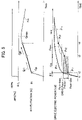
Fig. 5] Fig. 5 is a timing chart illustrating changes in an accelerator opening degree APO, acceleration of the electric-powered vehicle, and electric power Pm supplied to adrive motor 6 over time. - [
Fig. 6] Fig. 6 is a timing chart illustrating changes in parameters according to the embodiment over time in the case where anengine 1 is not rotating. - [
Fig. 7] Fig. 7 is a timing chart illustrating changes in the parameters according to the embodiment over time in the case where theengine 1 is rotating. - [
Fig. 8] Fig. 8 is a timing chart explaining operations and effects of the embodiment. - Next, an embodiment of the present invention is described in detail with reference to the drawings. In the description, the same parts are denoted by the same reference numerals and overlapping description is omitted.
- A configuration of an electric-powered vehicle in which a vehicle control device according to the embodiment is mounted is described with reference to
Fig. 1 . The electric-powered vehicle of the embodiment is a series hybrid car including: an engine 1 (internal combustion engine); a power generator 4 (first electric motor) mechanically connected to an output shaft of theengine 1; abattery 5 electrically connected to thepower generator 4;drive wheels drive wheels motor controller 12 configured to control thedrive motor 6; apower generator controller 14 configured to control thepower generator 4; anengine controller 13 configured to control theengine 1; anengine condition sensor 9 configured to detect conditions of theengine 1 including the number of revolutions and oil temperature of theengine 1; awheel speed sensor 3 configured to detect wheel speed; an acceleratoropening degree sensor 8 configured to detect an accelerator opening degree APO; and avehicle controller 11 configured to control the entire powertrain of the electric-powered vehicle. In the series hybrid car, theengine 1 does not drive thedrive wheels drive motor 6 drives thedrive wheels - The output shaft of the
engine 1 is mechanically connected to the input shaft of thepower generator 4. Thepower generator 4 is electrically connected to thebattery 5 and thedrive motor 6 to be capable of exchanging electric power (high power) therewith. The output shaft of thedrive motor 6 is mechanically connected to an axle via a gear 2 and the axle is mechanically connected to thedrive wheels - The
motor controller 12 and thedrive motor 6, thepower generator controller 14 and thepower generator 4, and theengine controller 13 and theengine 1 are connected to one another to be capable of exchanging electric signals (low power). Moreover, themotor controller 12, thepower generator controller 14, and theengine controller 13 are connected to thevehicle controller 11 to be capable of exchanging electric signals (low power) therewith. - The
engine condition sensor 9 sends the detected engine conditions to thevehicle controller 11 as electric signals. Theengine condition sensor 9 includes an engine oil temperature detection sensor and an engine speed detection sensor. Thewheel speed sensor 3 sends the detected wheel speed to thevehicle controller 11 as electric signals. The acceleratoropening degree sensor 8 sends the detected accelerator opening degree APO to thevehicle controller 11 as electric signals. - The drive force of the
engine 1 is transmitted to thepower generator 4 and thepower generator 4 generates electric power by using the drive force of theengine 1. The electric power generated by thepower generator 4 is transmitted to thedrive motor 6 or is stored in thebattery 5. The electric power stored in thebattery 5 is transmitted to thedrive motor 6 and thedrive motor 6 is driven by the electric power stored in thebattery 5 and the electric power generated by thepower generator 4. The drive force of thedrive motor 6 is transmitted to thedrive wheels drive wheels drive motor 6 and the electric-powered vehicle (hereafter, referred to in short as vehicle) travels. - The
vehicle controller 11 functions as the vehicle control device according to the embodiment. - For example, the
vehicle controller 11 can be implemented by a general-purpose micro-computer including a CPU (central processing unit), a memory, and an input-output unit. A computer program (vehicle control program) which causes the micro-computer to function as thevehicle controller 11 is installed in the micro-computer and is executed. The general-purpose micro-computer thereby functions as thevehicle controller 11. Note that, although the example in which thevehicle controller 11 is implemented by software is described herein, thevehicle controller 11 may be configured by preparing dedicated hardware for executing the following information processes, as a matter of course. Moreover, multiple units (21 to 26 and 31 to 35) included in thevehicle controller 11 may be configured of separate pieces of hardware. Furthermore, in addition to thevehicle controller 11, themotor controller 12, thepower generator controller 14, and theengine controller 13 may be similarly implemented by software or dedicate hardware. Moreover, an electronic control unit (ECU) used for other control relating to the vehicle may also serve as thevehicle controller 11, themotor controller 12, thepower generator controller 14, and theengine controller 13. - Functional components included in the
vehicle controller 11 are described with reference toFig. 2 . Thevehicle controller 11 includes adrive force converter 21, arate limiter processor 22, afilter processor 23, astretchiness processor 24, asafety determiner 25, and a powergeneration control unit 26. Thestretchiness processor 24 includes a control start determiner 31, apower generation requester 32, and aGj adder 33. TheGj adder 33 includes aGj1 adder 34 and aGj2 adder 35. - The
drive force converter 21 calculates drive force (driver request drive force) which a driver requests thedrive motor 6 to output from the accelerator opening degree APO detected by the acceleratoropening degree sensor 8 and the wheel speed detected by thewheel speed sensor 3. Thevehicle controller 11 has in advance a not-illustrated drive force map. The drive force map is a graph depicting relationships between the vehicle speed and the driver request drive force and thevehicle controller 11 has the drive force map for each accelerator opening degree. - The
rate limiter processor 22 performs a rate limit process of adding certain limit to a change rate of the driver request drive force and making changes in the driver request drive force smoother to suppress abrupt changes in the driver request drive force. Thereafter, thefilter processor 23 performs a low-pass filter process on the driver request drive force to make the changes in the driver request drive force even smoother. - The driver request drive force subjected to the filter process is inputted into the
stretchiness processor 24. "Stretchiness" is a phenomenon in which smooth acceleration feeling or acceleration feeling expected in response to stepping-on of the accelerator cannot be obtained. The "stretchiness" is described later with reference to the graph ofFig. 8 . - In order to suppress the stretchiness, first, the
stretchiness processor 24 limits drive force Fm outputted by thedrive motor 6 to a lower level than maximum drive force determined from the electric power (drive Pout) which can be supplied by thebattery 5 to drive the vehicle. - Specifically, as illustrated in
Fig. 5 , a value obtained by subtracting electric power (accessory electric power) consumed by accessories such as an air conditioner, an audio device, and the like mounted in the vehicle and electric power (engine firing-up electric power) required to fire up theengine 1 from electric power Pout_base which can be supplied by thebattery 5 is the electric power (drive Pout) which can be supplied by thebattery 5 as the drive force of the vehicle. The drive Pout corresponds to the electric power which can be supplied by thebattery 5 to drive the vehicle. - Note that, in the state where the engine is not rotating, the engine firing-up electric power corresponds to electric power (cranking electric power) required for a cranking process of the
engine 1. In the state where the engine is already rotating, the engine firing-up electric power corresponds to electric power (recovery electric power) required for a recovery process of theengine 1. - As illustrated in
Fig. 5 , thestretchiness processor 24 causes power-saving electric power Pou_savi limited to a lower level than the drive Pout to be supplied from thebattery 5 to thedrive motor 6. The drive force Fm outputted by thedrive motor 6 is thereby limited to a battery drive limit threshold Ft lower than maximum drive force determined from the electric power which can be supplied by thebattery 5 to drive the vehicle. - Next, as illustrated by the arrow Gj1 (first gradient) of
Fig. 5 , thestretchiness processor 24 increases the drive force Fm outputted by thedrive motor 6 by using the electric power supplied by thebattery 5 over time, in a period from when thedrive motor 6 outputs the drive force limited to the lower level (battery drive limit threshold Ft) to when theengine 1 is fired up and thepower generator 4 starts power generation (t3). - Specifically, as illustrated in
Fig. 5 , after electric power Pm supplied from thebattery 5 to thedrive motor 6 reaches the power-saving electric power Pou_savi, thestretchiness processor 24 increases the electric power Pm supplied from thebattery 5 to thedrive motor 6 over time. The drive force Fm outputted by thedrive motor 6 by using the electric power supplied by thebattery 5 can be thereby increased over time as illustrated by the gradient Gj1 ofFig. 5 . The increase rate of the electric power Pm from electric power Pt1 to electric power Pt2 can be calculated from the gradient Gj1 ofFig. 5 and the vehicle speed. - The
stretchiness processor 24 sets the power-saving electric power Pou_savi and the increase rate of the electric power Pm from the electric power Pt1 to the electric power Pt2 such that the electric power Pt2 at the firing-up of theengine 1 and the start of the power generation by the power generator 4 (t3) is not greater than the drive Pout. The electric power Pm supplied from thebattery 5 to thedrive motor 6 can be thereby made to increase over time in the period (t1 to t3) from when the accelerator is stepped on to when theengine 1 is fired up and thepower generator 4 starts the power generation. The drive force (drive torque) thereby increases over time without stagnation. Accordingly, acceleration G smoothly and continuously increases and this achieves smooth acceleration feeling. The smooth acceleration feeling or the acceleration feeling expected in response to the stepping-on of the accelerator is obtained and the stretchiness is suppressed. Thus, discomfort or frustration which may be felt by the driver or other occupants of the vehicle is eliminated. - The
stretchiness processor 24 can set the power-saving electric power Pou_savi to a value obtained by subtracting surplus electric power Pdown, determined depending on the time required to fire up theengine 1, from the drive Pout. The battery drive limit threshold Ft can be thereby set to a value obtained by subtracting surplus drive force, determined depending on the time required to fire up theengine 1, from the maximum drive force determined from the electric power which can be supplied by thebattery 5 to drive the vehicle. Thus, the battery drive limit threshold Ft can be accurately estimated. Note that the time required to fire up the engine 1 (cranking period Cra) is time (t2 to t3) required for firing-up determination of theengine 1 and the cranking process of theengine 1. The cranking period Cra can be estimated based on the engine oil temperature. "EV" inFig. 5 denotes an EV state before the firing-up determination of theengine 1 and "Gen" denotes a power generation state after the firing-up of theengine 1. - The
stretchiness processor 24 may determine the surplus electric power Pdown with reference not only to the time required to fire up theengine 1 but also the increase rate of the electric power Pm. In other words, thestretchiness processor 24 can set the power-saving electric power Pou_savi to a value obtained by subtracting the surplus electric power Pdown, determined based on the time required to fire up theengine 1 and the increase rate of the electric power Pm, from the drive Pout. Specifically, thestretchiness processor 24 calculates the surplus electric power Pdown by multiplying the increase rate of the electric power Pm by the time required to fire up theengine 1. The battery drive limit threshold Ft can be thereby set to a value obtained by subtracting the surplus drive force, determined depending on the time required to fire up theengine 1 and the first gradient (Gj1) of the drive force, from the maximum drive force determined from the electric power which can be supplied by thebattery 5 to drive the vehicle. Thus, the battery drive limit threshold Ft can be more accurately estimated. - The maximum value of the electric power which can be supplied to the
drive motor 6 before the firing-up of theengine 1 and the start of the power generation by the power generator 4 (to t3) is the drive Pout. Meanwhile, after the firing-up of theengine 1 and the start of the power generation by the power generator 4 (from t3), electric power Peon generated by thepower generator 4 is added to the drive Pout. Accordingly, electric power equal to or more than the drive Pout can be supplied to thedrive motor 6. Then, the electric power Pm supplied to thedrive motor 6 is set close to driver request electric power Pd by controlling the number of revolutions of theengine 1 to increase the electric power Peon. Increasing the electric power Pm over time without stagnation also after the firing-up of theengine 1 and the start of the power generation by the power generator 4 (from t3) can smoothly increase the drive force Fm (drive torque) to its maximum value Gmax over time without stagnation. - Next, detailed functional configurations of the
stretchiness processor 24 are described. - First, when the drive force (driver request drive force) which the
drive motor 6 is requested to output is equal to the predetermined battery drive limit threshold Ft or higher than the battery drive limit threshold Ft, the control startdeterminer 31 determines that the stretchiness may occur and starts a process of suppressing the stretchiness. Specifically, the higher the accelerator opening degree APO is, the higher the drive force Fm which thedrive motor 6 is requested to output is. When the driver request drive force is equal to or more than the battery drive limit threshold Ft, the control startdeterminer 31 starts the process of firing up theengine 1. When the drive force Fm is less than the battery drive limit threshold Ft, the control startdeterminer 31 does not start the process of firing up theengine 1. The need for firing-up theengine 1 can be thereby appropriately determined. Note that, in this case, no fuel is supplied to theengine 1 and theengine 1 is not in a combustion state. Moreover, the output shaft of theengine 1 is not rotating and theengine 1 is in a stopped state. - Moreover, when the drive force Fm which the
drive motor 6 is requested to output becomes lower than the battery drive limit threshold Ft after the start of the process of firing up theengine 1, the control startdeterminer 31 suspends the process of firing up theengine 1. This corresponds to, for example, the case where the accelerator is stepped on and then released. The need for firing up theengine 1 can be thereby appropriately determined. Note that the battery drive limit threshold Ft used in the determination of the start and suspension of the process of firing up theengine 1 desirably has a certain hysteresis to suppress hunting and stabilize control of firing-up theengine 1. - The control start
determiner 31 outputs the determination result of the engine firing-up to theGj adder 33 and the powergeneration control unit 26 as a start determination flag. At the same time, the control startdeterminer 31 outputs the time required to fire up the engine 1 (cranking time) to theGj adder 33 and the powergeneration control unit 26. - The
Gj1 adder 34 calculates the battery drive limit threshold Ft. Specifically, theGj1 adder 34 calculates the surplus electric power Pdown from the cranking time obtained from the engine oil temperature. Then, theGj1 adder 34 subtracts the surplus electric power Pdown from the drive Pout to obtain the power-saving electric power Pou_savi and calculates the battery drive limit threshold Ft from the power-saving electric power Pou_savi and the vehicle speed. - The
Gj1 adder 34 increases the drive force Fm at the first gradient (Gj1) after the drive force Fm reaches the battery drive limit threshold Ft. The increase of the drive force Fm at the first gradient (Gj1) is performed until theengine 1 is fired up (to t3). The amount of the increase of the drive force Fm at the first gradient (Gj1) corresponds to the surplus drive force determined depending on the time required to fire up theengine 1 and the surplus electric power Pdown is used for this increase. TheGj1 adder 34 calculates the increase rate of the electric power Pm required to increase the drive force Fm at the first gradient (Gj1). - The
Gj2 adder 35 increases the drive force Fm at the second gradient (Gj2) after the firing-up of the engine 1 (from t3). The electric power (consumable electric power Peon) generated by thepower generator 4 is used for the increase of the drive force Fm at the second gradient (Gj2). TheGj2 adder 35 calculates the increase rate of the consumable electric power Peon required to increase the drive force Fm at the second gradient (Gj2). - The
Gj adder 33 sends the power-saving electric power Pou_savi, the increase rate of the electric power Pm required to increase the drive force Fm at the first gradient (Gj1), and the increase rate of the consumable electric power Peon required to increase the drive force Fm at the second gradient (Gj2) to thesafety determiner 25 and the powergeneration control unit 26. - When the battery drive limit threshold Ft is lower than predetermined minimum drive force Fa, the power generation requester 32 requests rotation of the output shaft of the
engine 1. Low outside temperature, a poor state of charge (SOC) of thebattery 5, or degradation of thebattery 5 causes the drive Pout to decrease and thus also causes the battery drive limit threshold Ft to decrease. Since the possibility of the request of power generation to thepower generator 4 increases with such a decrease, the output shaft of theengine 1 is rotated in advance to prepare for a future power generation request. Rotating the output shaft in advance can reduce the time required to fire up theengine 1 compared to that in the state where the output shaft is not rotated. In this case, "rotation of the output shaft" is a concept including not only firing control in which fuel is supplied to the engine and the engine is fired up but also motoring control in which thepower generator 4 forcedly rotates the rotary shaft of theengine 1 to which fuel supply is cut-off. - The power generation requester 32 limits in advance the number of revolutions in the rotation of the output shaft of the
engine 1 to the number of revolutions required for thepower generator 4 to generate predetermined minimum generation electric power. This number of revolutions is the number of revolutions at which thepower generator 4 can generate the minimum generation electric power when the power is generated at the maximum torque of the engine. In other words, the minimum value of the number of revolutions in the rotation of the output shaft of theengine 1 is set in advance to the number of revolutions required for thepower generator 4 to generate the predetermined minimum generation electric power. The fuel supplied to theengine 1 for the rotation and the electric power consumed by thepower generator 4 can be thereby secured. - The power generation requester 32 can determine the predetermined minimum generation electric power from the battery suppliable electric power and drive force which causes acceleration change of a predetermined degree or more. Specifically, the power generation requester 32 sets a difference between the electric power suppliable from the battery and the generation electric power required for the
drive motor 6 to output drive force which causes a predetermined amount of change in acceleration, as a predetermined minimum generation electric power value. This can prevent frustration in which, when the amount of change in the acceleration is small, the driver cannot feel the acceleration G of the vehicle expected in response to the stepping-on of the accelerator. - The power generation requester 32 sets maximum generation electric power which is the maximum value of the electric power to be generated by the
power generator 4 such that surplus electric power obtained by subtracting the electric power used in the vehicle from the electric power generated by thepower generator 4 is equal to or less than electric power which can be stored in thebattery 5. In other words, the power generation requester 32 can determine the maximum generation electric power from the electric power which can be stored in thebattery 5. The electric power generated by thepower generator 4 is limited to the maximum generation electric power or less. Specifically, the power generation requester 32 sets a predetermined maximum generation electric power value for the electric power to be generated by thepower generator 4 such that the surplus electric power obtained when the generated electric power exceeds the electric power used in the vehicle can be made lower than the electric power which can be stored in thebattery 5. In this case, the lower the electric power which can be stored in thebattery 5 is, the lower the maximum generation electric power is set. This can preferentially prevent overcharging of thebattery 5. When the "electric power which can be stored in thebattery 5" is low, the overcharging of thebattery 5 is prevented in preference to the frustration in which the driver cannot feel the acceleration G of the vehicle expected in response to the stepping-on of the accelerator, to suppress occurrence of failure in thebattery 5. - The power generation requester 32 sends the request for the rotation of the output shaft of the
engine 1, the maximum generation electric power, and the minimum generation electric power to the powergeneration control unit 26. - The
safety determiner 25 determines whether the power-saving electric power Pou_savi, the increase rate of the electric power Pm required to increase the drive force Fm at the first gradient (Gj1), and the increase rate of the consumable electric power Peon required to increase the drive force Fm at the second gradient (Gj2) satisfy conditions for safely operating thedrive motor 6 and performs processes required for a safe operation on these parameters. After performing these determination and processes, thesafety determiner 25 instructs themotor controller 12 about the power-saving electric power Pou_savi, the increase rate of the electric power Pm required to increase the drive force Fm at the first gradient (Gj1), and the increase rate of the consumable electric power Peon required to increase the drive force Fm at the second gradient (Gj2). - The power
generation control unit 26 instructs theengine controller 13 to fire up theengine 1 and instructs theengine controller 13 about the number of revolutions of the engine based on the increase rate of the consumable electric power Peon required to increase the drive force Fm at the second gradient (Gj2). The powergeneration control unit 26 instructs thepower generator controller 14 to rotate the output shaft of theengine 1 by the motoring control. - Next, processes in which the
stretchiness processor 24 obtains the battery drive limit threshold Ft are described with reference to the flowchart ofFig. 3 . - In
process 41, thestretchiness processor 24 obtains the drive Pout by subtracting the electric power (accessory electric power) consumed by the accessories and the cranking electric power (or the recovery electric power) from the electric power Pout_base. - In
process 42, thestretchiness processor 24 obtains the drive force (drive torque) of the vehicle obtained from the drive Pout, from the vehicle speed and the drive Pout by using the drive force map. - In
process 45, thestretchiness processor 24 obtains the surplus drive force by multiplying the first gradient Gj1 (Gj1 torque rate value 43) by the time required to fire up the engine 1 (cranking time 44). Inprocess 46, thestretchiness processor 24 obtains the battery drive limit threshold Ft by subtracting the surplus drive force from the drive force of the vehicle obtained from the drive Pout. - In
process 47, thestretchiness processor 24 compares the battery drive limit threshold Ft, the creep torque, and zero and selects the greatest value among these values. In other words, thestretchiness processor 24 sets the battery drive limit threshold Ft to a value on the power running side and greater than the drive force outputted by thedrive motor 6 in a state where the accelerator of the vehicle is off. This can prevent theengine 1 from continuing to run in the off state of the accelerator. Moreover, thedrive motor 6 can be maintained in a state where thedrive motor 6 outputs positive torque, that is in the power running state. - The
stretchiness processor 24 can obtain the battery drive limit threshold Ft through the aforementioned processes. - An operation example (vehicle control method) of the
vehicle controller 11 inFig. 2 is explained with reference to the flowchart ofFig. 4 . - In step S01, the
vehicle controller 11 reads input signals indicating the accelerator opening degree APO, a shift position, the vehicle speed, the engine oil temperature, the state of charge (SOC) of thebattery 5, and the electric power Pout_base. - Proceeding to step S03, the
vehicle controller 11 calculates the driver request drive force Fd based on the accelerator opening degree, the vehicle speed, and the shift position. Proceeding to step S05, thevehicle controller 11 calculates the battery drive limit threshold Ft and, proceeding to step S07, calculates the minimum drive force Fa. - Proceeding to step S09, the vehicle controller 11 (power generation requester 32) determines whether the battery drive limit threshold Ft is lower than the minimum drive force Fa. When the determination result is yes (YES in S09), the operation proceeds to step S11 and, when the determination result is no (NO in S09), the operation proceeds to step S13.
- In step S11, the vehicle controller 11 (power generation requester 32) requests the rotation of the output shaft of the
engine 1. Since the possibility of the power generation request to thepower generator 4 increases when the battery drive limit threshold Ft is low, the output shaft of theengine 1 is rotated in advance to prepare for a future power generation request. Thereafter, the operation proceeds to step S13. - In step S13, the
vehicle controller 11 determines whether the driver request drive force Fd is higher than the battery drive limit threshold Ft. When the determination result is yes (YES in S13), thevehicle controller 11 determines that there is possibility of occurrence of stretchiness and causes the operation to proceed to step S15. Meanwhile, when the determination result is no (NO in S13), thevehicle controller 11 determines that there is no possibility of occurrence of stretchiness and the flowchart ofFig. 4 is terminated. - In step S15, the
vehicle controller 11 starts the process of suppressing the stretchiness, specifically the process of firing up the engine 1 (cranking process or recovery process). In step S17, thevehicle controller 11 calculates the drive force rate limit values (Gj1, Gj2) by referring to the vehicle speed. Preceding to step S19, theGj adder 33 calculates the drive force Fm subjected to the rate limit process in which the gradients (Gj1, Gj2) of the drive force in the acceleration are limited. - Proceeding to step S21, the
vehicle controller 11 determines whether the drive force Fm has reached the driver request drive force Fd. When the determination result is yes (YES in S21), the control by thevehicle controller 11 is terminated. When the determination result is no (NO in S21), the operation returns to step S19. - Changes in the respective parameters over time when the accelerator is stepped on in the state where the
engine 1 is not rotating (an example of the "state where theengine 1 is stopped") are described with reference to the timing chart ofFig. 6 . The accelerator opening degree APO increases due to the stepping-on of the accelerator (t1). In response to this, the driver request drive forces (Fd, Fd') increase. The driver request drive force Fd is a parameter obtained by subjecting the driver request drive force Fd' to the rate limit process performed by therate limiter processor 22 and thefilter processor 23. - The drive force Fm outputted by the
drive motor 6 also increases in response to the driver request drive force Fd after lapse of response time. When the driver request drive force Fd exceeds the battery drive limit threshold Ft (t2), the power generation start flag changes from alogical value 0 to alogical value 1 and the process of firing up the engine 1 (cranking period: Cra) is started. The number of revolutions of theengine 1 thereby increases. With this increase, a target drive force Tr_eng* of theengine 1 increases. Note that, in the cranking period Cra, actual drive force Tr_eng actually outputted by theengine 1 is a negative value. - The increase of the drive force Fm is limited to the battery drive limit threshold Ft (not illustrated). The drive force Fm outputted by the
drive motor 6 increases at the first gradient Gj1 in the period from when the drive force Fm reaches the battery drive limit threshold Ft to when theengine 1 is fired up (t2 to t3). The drive force Fm outputted by thedrive motor 6 increases at the second gradient Gj2 after the firing-up of the engine 1 (from t3). Regarding the first gradient Gj1 and the second gradient Gj2 which each indicate an increase amount of the drive force Fm per unit time, the first gradient Gj1 is set to be smaller than the second gradient Gj2. - The first gradient Gj1 of the drive force Fm outputted by the
drive motor 6 in the period from when thedrive motor 6 outputs the drive force limited to the lower level (battery drive limit threshold Ft) to when theengine 1 is fired up and thepower generator 4 starts the power generation (t2 to t3) is set to be smaller than the second gradient Gj2 of the drive force outputted by thedrive motor 6 after the start of the power generation by the power generator 4 (from t3),. Even smoother acceleration feeling can be thereby obtained and discomfort or frustration which may be felt by the driver or other occupants of the vehicle is eliminated. - The increase of the drive force Fm at the second gradient Gj2 continues until the drive force Fm reaches the driver request drive force Fd. Note that, after the start of the power generation by the power generator 4 (from t3), the actual drive force Tr_eng is on the power running side and the number of revolutions of the engine increases over time. Moreover, the vehicle speed increases over time with the generation and increase of the drive force Fm.
- Changes in the respective parameters over time when the accelerator is stepped on in the state where the
engine 1 is rotating (another example of the "state where theengine 1 is stopped") are described with reference to the timing chart ofFig. 7 . The process of firing up the engine 1 (recovery period) is different from that inFig. 6 . The recovery period Rec ofFig. 7 is shorter than the cranking period Cra ofFig. 6 . Accordingly, the time from when the power generation start flag changes from 0 to 1 to when the power generation is started (t2 to t3) is shorter than that inFig. 6 and the first gradient Gj1 of the drive force Fm is greater than that inFig. 6 . Since the second gradient Gj2 is greater than the first gradient Gj1, the second gradient Gj2 of the drive force Fm is also greater than that inFig. 6 . As a result, the driver force Fm reaches the driver request drive force Fd in shorter time than inFig. 6 . Other points of the timing chart ofFig. 7 are the same as those ofFig. 6 and description thereof is omitted. The "state where theengine 1 is stopped" means the state where theengine 1 is not fired up, that is the state where no fuel is supplied to theengine 1. In the "state where theengine 1 is stopped," whether the output shaft of theengine 1 is rotating or not does not matter. - Operations and effects of the embodiment are described with reference to the timing chart of
Fig. 8 . A curve Pm illustrates a change in electric power pm over time according to a comparative example and a curve Pm illustrates a change in electric power Pm over time according to the embodiment. A curve fm illustrates a change in drive force (drive torque fm) over time according to the comparative example and a curve Fm illustrates a change in drive force (drive torque Fm) over time according to the embodiment. The electric power refers to the electric power supplied to thedrive motor 6. - The driver request electric power Pd increases and exceeds the drive Pout due to rising of the accelerator opening degree APO. The electric power pm of the comparative example increases to the drive Pout along the driver request electric power Pd. When the electric power pm increases to the drive Pout, the
engine 1 is not fired up yet and thus the power generation is not started. Accordingly, the electric power pm of the comparative example stagnates around the drive Pout until the power generation is started (to t3). - Accordingly, the drive torque fm according to the comparative example increases to a certain value by the increase of the electric power pm to the drive Pout but then decreases due to the stagnation of the electric power pm and starts to increase again when the
engine 1 is fired up. As described above, the shape of the curve illustrating the change in the drive torque fm over time according to the comparative example is not similar to the shape of the curve illustrating the change in the driver request drive force Fd over time. In the curve of the drive torque fm according to the comparative example, the drive torque fm repeats rising and falling and it cannot be said that the drive torque fm smoothly and continuously increases. Accordingly, the smooth acceleration feeling or the acceleration feeling expected in response to the stepping-on of the accelerator cannot be obtained and the driver or other occupants of the vehicle feels discomfort or frustration in some cases. - Meanwhile, the electric power Pm of the embodiment increases along the driver request electric power Pd but the increase is limited to a value lower than the drive Pout (power-saving electric power Pou_savi). Then, in the period from when the electric power Pm limited to the level lower than the drive Pout is supplied to the
drive motor 6 to when theengine 1 is fired up and thepower generator 4 starts the power generation (t2 to t3), the electric power Pm supplied by thebattery 5 is made to increase over time as illustrated by the arrow ofFig. 8 . In this case, the increase rate of the electric power Pm and the power-saving electric power Pou savi are set such that the electric power Pm at the firing-up of theengine 1 and the start of the power generation by the power generator 4 (t3) is not greater than the drive Pout. - The drive torque Fm according to the embodiment thereby increases over time without stagnation until the
engine 1 is fired up (to t3). The shape of the curve illustrating the change in the drive torque Fm over time according to the embodiment is similar to the shape of the curve illustrating the change in the driver request drive force Fd over time. In the curve of the drive torque Fm according to the embodiment, the drive torque Fm smoothly and continuously increases. Accordingly, it is possible to obtain the smooth acceleration feeling or the acceleration feeling expected in response to the stepping-on of the accelerator and suppress the discomfort or frustration felt by the driver or other occupants of the vehicle. - The present invention includes various embodiments and the like which are not described herein as a matter of course. Accordingly, the technical scope of the present invention is determined only by the matters specifying the invention according to the claims regarded as appropriate from the aforementioned description.
- The functions described in the aforementioned embodiment may be implemented by one or multiple processing circuits. The processing circuits include programed processing devices such as processing devices including electric circuits. Moreover, the processing circuits include devices such as application specific integrated circuit (ASIC) and conventional circuit parts which are arranged to execute the functions described in the embodiment.
-
- 1
- engine (internal combustion engine)
- 4
- power generator (first electric motor)
- 5
- battery
- 6
- drive motor (second electric motor)
- Fa
- minimum drive force
- Fd
- drive force which second electric motor is requested to output
- Ft
- battery drive limit threshold
- Gj1
- first gradient of drive force
- Gj2
- second gradient of drive force
Claims (13)
- A vehicle control method for a vehicle control device (11) configured to control an electric-powered vehicle,
the vehicle including:- an internal combustion engine (1);- a first electric motor (4) mechanically connected to an output shaft of the internal combustion engine (1);- a battery (5) electrically connected to the first electric motor (4); and- a second electric motor (6) mechanically connected to a drive wheel (7a, 7b) included in the electric-powered vehicle and configured to drive the drive wheel (7a, 7b) by using electric power generated by the first electric motor (4) and electric power supplied from the battery (5),the vehicle control method comprising:- when drive force (Fm) which the second electric motor (6) is requested to output increases in a state where the internal combustion engine (1) is stopped, limiting drive force (Fm) which the second electric motor (6) outputs by using the electric power supplied by the battery (5) to a lower level (Ft) than maximum drive force (Gmax) determined from electric power which the battery (5) is capable of supplying to drive the electric-powered vehicle; and- increasing the drive force (Fm) which the second electric motor (6) outputs by using the electric power supplied by the battery (5), over time in a period from when the second electric motor (6) outputs the drive force (Fm) limited to the lower level (Ft) to when the internal combustion engine (1) is fired up and the first electric motor (4) starts power generation. - The vehicle control method for the vehicle control device (11) according to claim 1, wherein the drive force (Fm) limited to the lower level (Ft) is a battery drive limit threshold (Ft) which is a value obtained by subtracting surplus drive force from the maximum drive force (Gmax), the surplus drive force determined depending on time required to fire up the internal combustion engine (1).
- The vehicle control method for the vehicle control device (11) according to claim 1, wherein the drive force (Fm) limited to the lower level (Ft) is a battery drive limit threshold (Ft) which is a value obtained by subtracting surplus drive force from the maximum drive force (Gmax), the surplus drive force determined depending on time required to fire up the internal combustion engine (1) and a first gradient (Gj1) of the drive force (Fm).
- The vehicle control method for the vehicle control device (11) according to claim 2 or 3, wherein when the drive force (Fm) which the second electric motor (6) is requested to output is equal to the battery drive limit threshold or higher than the battery drive limit threshold, a process of firing up the internal combustion engine (1) is started.
- The vehicle control method for the vehicle control device (11) according to claim 4, wherein when the drive force (Fm) which the second electric motor (6) is requested to output becomes lower than the battery drive limit threshold after the start of the process of firing up the internal combustion engine (1), the process of firing up the internal combustion engine (1) is suspended.
- The vehicle control method for the vehicle control device (11) according to claim 2 or 3, wherein when the battery drive limit threshold is lower than predetermined minimum drive force, the output shaft of the internal combustion engine (1) is rotated.
- The vehicle control method for the vehicle control device (11) according to claim 2 or 3, wherein the battery drive limit threshold is on the power running side and is greater than the drive force (Fm) output by the second electric motor (6) in a state where an accelerator of the electric-powered vehicle is off.
- The vehicle control method for the vehicle control device (11) according to claim 6, wherein the number of revolutions in the rotation of the output shaft of the internal combustion engine (1) is limited to the number of revolutions required for the first electric motor (4) to generate predetermined minimum generation electric power.
- The vehicle control method for the vehicle control device (11) according to claim 6, wherein a first gradient (Gj1) of the drive force (Fm) output by the second electric motor (6) in the period from when the second electric motor (6) outputs the drive force (Fm) limited to the lower level (Ft) to when the internal combustion engine (1) is fired up and the first electric motor (4) starts power generation is set to be smaller than a second gradient (Gj2) of the drive force (Fm) output by the second electric motor (6) after the start of the power generation by the first electric motor (4).
- The vehicle control method for the vehicle control device (11) according to claim 8, wherein the minimum generation electric power is determined from the drive force (Fm) which causes acceleration change of a predetermined degree or more.
- The vehicle control method for the vehicle control device (11) according to any one of claims 1 to 10, wherein maximum generation electric power which is a maximum value of electric power to be generated by the first electric motor (4) is determined depending on electric power storable in the battery (5).
- The vehicle control method for the vehicle control device (11) according to claim 2 or 3, wherein the lower an outside air temperature is, the lower the battery drive limit threshold is set.
- A vehicle control device (11) configured to control an electric-powered vehicle,
the vehicle including:- an internal combustion engine (1);- a first electric motor (4) mechanically connected to an output shaft of the internal combustion engine (1);- a battery 5 electrically connected to the first electric motor (4); and- a second electric motor (6) mechanically connected to a drive wheel (7a, 7b) included in the electric-powered vehicle and configured to drive the drive wheel (7a, 7b) by using electric power generated by the first electric motor (4) and electric power supplied from the battery (5),wherein:- when drive force (Fm) which the second electric motor (6) is requested to output increases in a state where the internal combustion engine (1) is stopped, the vehicle control device (11) is configured to limit drive force (Fm) which the second electric motor (6) outputs by using the electric power supplied by the battery (5) to a lower level (Ft) than maximum drive force (Gmax) determined from the electric power which the battery (5) is capable of supplying, and- the vehicle control device (11) is configured to increase the drive force (Fm) which the second electric motor (6) outputs by using the electric power supplied by the battery (5), over time in a period from when the second electric motor (6) outputs the drive force (Fm) limited to the lower level (Ft) to when the internal combustion engine (1) is fired up and the first electric motor (4) starts power generation.
Applications Claiming Priority (1)
| Application Number | Priority Date | Filing Date | Title |
|---|---|---|---|
| PCT/JP2017/045163 WO2019116552A1 (en) | 2017-12-15 | 2017-12-15 | Vehicle control method and vehicle control device |
Publications (3)
| Publication Number | Publication Date |
|---|---|
| EP3725618A1 EP3725618A1 (en) | 2020-10-21 |
| EP3725618A4 EP3725618A4 (en) | 2020-12-16 |
| EP3725618B1 true EP3725618B1 (en) | 2022-08-24 |
Family
ID=66819106
Family Applications (1)
| Application Number | Title | Priority Date | Filing Date |
|---|---|---|---|
| EP17934487.4A Active EP3725618B1 (en) | 2017-12-15 | 2017-12-15 | Vehicle control method and vehicle control device |
Country Status (8)
| Country | Link |
|---|---|
| US (1) | US11465604B2 (en) |
| EP (1) | EP3725618B1 (en) |
| JP (1) | JP6927326B2 (en) |
| KR (1) | KR102362854B1 (en) |
| CN (1) | CN111479735B (en) |
| MX (1) | MX2020006234A (en) |
| RU (1) | RU2748238C1 (en) |
| WO (1) | WO2019116552A1 (en) |
Families Citing this family (2)
| Publication number | Priority date | Publication date | Assignee | Title |
|---|---|---|---|---|
| DE102018208425B4 (en) * | 2018-05-28 | 2026-01-29 | Bayerische Motoren Werke Aktiengesellschaft | Powertrain for a motor vehicle, in particular for a motor car, and methods for operating such a powertrain |
| JP7424238B2 (en) * | 2020-07-27 | 2024-01-30 | 三菱自動車工業株式会社 | Vehicle driving control systems and hybrid vehicles |
Citations (1)
| Publication number | Priority date | Publication date | Assignee | Title |
|---|---|---|---|---|
| US20130096764A1 (en) * | 2010-06-25 | 2013-04-18 | Toyota Jidosha Kabushiki Kaisha | Electrically-powered vehicle and control method therefor |
Family Cites Families (12)
| Publication number | Priority date | Publication date | Assignee | Title |
|---|---|---|---|---|
| JP3997633B2 (en) | 1998-12-15 | 2007-10-24 | 日産自動車株式会社 | Vehicle driving force control device |
| JP2010179882A (en) * | 2009-02-09 | 2010-08-19 | Nissan Motor Co Ltd | Restart control device and method for vehicle |
| JP5305025B2 (en) * | 2009-07-06 | 2013-10-02 | スズキ株式会社 | Hybrid vehicle |
| US9180878B2 (en) * | 2011-10-28 | 2015-11-10 | Nissan Motor Co., Ltd. | Control device for hybrid vehicle |
| JP5957873B2 (en) * | 2011-12-21 | 2016-07-27 | スズキ株式会社 | Engine start control device |
| JP5838870B2 (en) * | 2012-03-13 | 2016-01-06 | トヨタ自動車株式会社 | Control device for hybrid vehicle |
| WO2013137278A1 (en) * | 2012-03-15 | 2013-09-19 | 日産自動車株式会社 | Hybrid vehicle control apparatus |
| CN104411555B (en) * | 2012-07-05 | 2017-04-12 | 丰田自动车株式会社 | Controls for hybrid vehicles |
| JP2014177255A (en) * | 2013-03-15 | 2014-09-25 | Aisin Seiki Co Ltd | Vehicle control device |
| JP6303422B2 (en) * | 2013-11-14 | 2018-04-04 | 日産自動車株式会社 | Control device for hybrid vehicle |
| JP2015202727A (en) * | 2014-04-11 | 2015-11-16 | トヨタ自動車株式会社 | vehicle |
| JP6315016B2 (en) * | 2016-03-25 | 2018-04-25 | トヨタ自動車株式会社 | Control device for hybrid vehicle |
-
2017
- 2017-12-15 JP JP2019558842A patent/JP6927326B2/en active Active
- 2017-12-15 WO PCT/JP2017/045163 patent/WO2019116552A1/en not_active Ceased
- 2017-12-15 EP EP17934487.4A patent/EP3725618B1/en active Active
- 2017-12-15 CN CN201780097641.5A patent/CN111479735B/en active Active
- 2017-12-15 RU RU2020123239A patent/RU2748238C1/en active
- 2017-12-15 MX MX2020006234A patent/MX2020006234A/en unknown
- 2017-12-15 US US16/771,337 patent/US11465604B2/en active Active
- 2017-12-15 KR KR1020207018405A patent/KR102362854B1/en not_active Expired - Fee Related
Patent Citations (1)
| Publication number | Priority date | Publication date | Assignee | Title |
|---|---|---|---|---|
| US20130096764A1 (en) * | 2010-06-25 | 2013-04-18 | Toyota Jidosha Kabushiki Kaisha | Electrically-powered vehicle and control method therefor |
Also Published As
| Publication number | Publication date |
|---|---|
| EP3725618A4 (en) | 2020-12-16 |
| BR112020011848A2 (en) | 2020-11-24 |
| RU2748238C1 (en) | 2021-05-21 |
| JP6927326B2 (en) | 2021-08-25 |
| JPWO2019116552A1 (en) | 2021-01-14 |
| CN111479735B (en) | 2023-06-06 |
| EP3725618A1 (en) | 2020-10-21 |
| KR20200088468A (en) | 2020-07-22 |
| WO2019116552A1 (en) | 2019-06-20 |
| US11465604B2 (en) | 2022-10-11 |
| KR102362854B1 (en) | 2022-02-15 |
| US20200339097A1 (en) | 2020-10-29 |
| CN111479735A (en) | 2020-07-31 |
| MX2020006234A (en) | 2020-08-24 |
Similar Documents
| Publication | Publication Date | Title |
|---|---|---|
| CN102653238B (en) | Vehicle control device and vehicle control method | |
| JP2004135417A (en) | Control device for vehicle | |
| CN102806908B (en) | For the method for the operational power system in response to accessory load | |
| EP3725581A1 (en) | Regenerative braking control method and regenerative braking control device | |
| US10322714B2 (en) | Hybrid vehicle and control method for same | |
| JP2013208944A (en) | Hybrid vehicle | |
| CN106627566A (en) | Method and apparatus for controlling a powertrain system during deceleration | |
| US9718458B2 (en) | Vehicle | |
| JP5029561B2 (en) | Vehicle control device | |
| JP6075018B2 (en) | Electric vehicle control device, electric vehicle including the same, and electric vehicle control method | |
| EP4139155B1 (en) | Control system and method for controlling electrical power consumption by traction motor caused by wheel slip | |
| JP2016153268A (en) | Driving control device | |
| US11465604B2 (en) | Vehicle control method and vehicle control device | |
| JP2017150392A (en) | Vehicle control device | |
| JP2017005914A (en) | Automobile | |
| US20180056980A1 (en) | System and method of controlling engine clutch engagement during tcs operation of hybrid vehicle | |
| EP3725625B1 (en) | Method and device for controlling hybrid vehicle | |
| JP2020132116A (en) | Hybrid vehicle control device | |
| JP7601025B2 (en) | Vehicle control device | |
| JP2014043183A (en) | Hybrid vehicle | |
| JP2025002330A (en) | Hybrid vehicle control device | |
| BR112020011848B1 (en) | VEHICLE CONTROL METHOD AND VEHICLE CONTROL DEVICE | |
| JP2016084110A (en) | Vehicle control device | |
| JP6070497B2 (en) | Control device for hybrid vehicle | |
| JP2014189067A (en) | Controller for hybrid vehicle |
Legal Events
| Date | Code | Title | Description |
|---|---|---|---|
| STAA | Information on the status of an ep patent application or granted ep patent |
Free format text: STATUS: THE INTERNATIONAL PUBLICATION HAS BEEN MADE |
|
| PUAI | Public reference made under article 153(3) epc to a published international application that has entered the european phase |
Free format text: ORIGINAL CODE: 0009012 |
|
| STAA | Information on the status of an ep patent application or granted ep patent |
Free format text: STATUS: REQUEST FOR EXAMINATION WAS MADE |
|
| 17P | Request for examination filed |
Effective date: 20200622 |
|
| AK | Designated contracting states |
Kind code of ref document: A1 Designated state(s): AL AT BE BG CH CY CZ DE DK EE ES FI FR GB GR HR HU IE IS IT LI LT LU LV MC MK MT NL NO PL PT RO RS SE SI SK SM TR |
|
| AX | Request for extension of the european patent |
Extension state: BA ME |
|
| A4 | Supplementary search report drawn up and despatched |
Effective date: 20201113 |
|
| RIC1 | Information provided on ipc code assigned before grant |
Ipc: B60W 10/06 20060101ALI20201109BHEP Ipc: B60K 6/46 20071001ALI20201109BHEP Ipc: F02D 29/02 20060101ALI20201109BHEP Ipc: B60W 10/26 20060101ALI20201109BHEP Ipc: B60W 20/15 20160101ALI20201109BHEP Ipc: B60W 20/13 20160101AFI20201109BHEP Ipc: F02D 17/00 20060101ALI20201109BHEP Ipc: B60W 30/192 20120101ALI20201109BHEP Ipc: B60W 10/08 20060101ALI20201109BHEP Ipc: B60W 20/40 20160101ALI20201109BHEP Ipc: B60W 20/10 20160101ALI20201109BHEP |
|
| DAV | Request for validation of the european patent (deleted) | ||
| DAX | Request for extension of the european patent (deleted) | ||
| GRAP | Despatch of communication of intention to grant a patent |
Free format text: ORIGINAL CODE: EPIDOSNIGR1 |
|
| STAA | Information on the status of an ep patent application or granted ep patent |
Free format text: STATUS: GRANT OF PATENT IS INTENDED |
|
| RIC1 | Information provided on ipc code assigned before grant |
Ipc: B60W 20/20 20160101ALI20220419BHEP Ipc: B60W 30/192 20120101ALI20220419BHEP Ipc: B60W 20/40 20160101ALI20220419BHEP Ipc: B60W 20/15 20160101ALI20220419BHEP Ipc: B60W 20/10 20160101ALI20220419BHEP Ipc: B60W 10/06 20060101ALI20220419BHEP Ipc: F02D 17/00 20060101ALI20220419BHEP Ipc: F02D 29/02 20060101ALI20220419BHEP Ipc: B60K 6/46 20071001ALI20220419BHEP Ipc: B60W 10/26 20060101ALI20220419BHEP Ipc: B60W 10/08 20060101ALI20220419BHEP Ipc: B60W 20/13 20160101AFI20220419BHEP |
|
| INTG | Intention to grant announced |
Effective date: 20220512 |
|
| GRAS | Grant fee paid |
Free format text: ORIGINAL CODE: EPIDOSNIGR3 |
|
| GRAA | (expected) grant |
Free format text: ORIGINAL CODE: 0009210 |
|
| STAA | Information on the status of an ep patent application or granted ep patent |
Free format text: STATUS: THE PATENT HAS BEEN GRANTED |
|
| AK | Designated contracting states |
Kind code of ref document: B1 Designated state(s): AL AT BE BG CH CY CZ DE DK EE ES FI FR GB GR HR HU IE IS IT LI LT LU LV MC MK MT NL NO PL PT RO RS SE SI SK SM TR |
|
| REG | Reference to a national code |
Ref country code: CH Ref legal event code: EP |
|
| REG | Reference to a national code |
Ref country code: IE Ref legal event code: FG4D |
|
| REG | Reference to a national code |
Ref country code: AT Ref legal event code: REF Ref document number: 1513458 Country of ref document: AT Kind code of ref document: T Effective date: 20220915 Ref country code: DE Ref legal event code: R096 Ref document number: 602017061137 Country of ref document: DE |
|
| REG | Reference to a national code |
Ref country code: LT Ref legal event code: MG9D |
|
| REG | Reference to a national code |
Ref country code: NL Ref legal event code: MP Effective date: 20220824 |
|
| PG25 | Lapsed in a contracting state [announced via postgrant information from national office to epo] |
Ref country code: SE Free format text: LAPSE BECAUSE OF FAILURE TO SUBMIT A TRANSLATION OF THE DESCRIPTION OR TO PAY THE FEE WITHIN THE PRESCRIBED TIME-LIMIT Effective date: 20220824 Ref country code: RS Free format text: LAPSE BECAUSE OF FAILURE TO SUBMIT A TRANSLATION OF THE DESCRIPTION OR TO PAY THE FEE WITHIN THE PRESCRIBED TIME-LIMIT Effective date: 20220824 Ref country code: PT Free format text: LAPSE BECAUSE OF FAILURE TO SUBMIT A TRANSLATION OF THE DESCRIPTION OR TO PAY THE FEE WITHIN THE PRESCRIBED TIME-LIMIT Effective date: 20221226 Ref country code: NO Free format text: LAPSE BECAUSE OF FAILURE TO SUBMIT A TRANSLATION OF THE DESCRIPTION OR TO PAY THE FEE WITHIN THE PRESCRIBED TIME-LIMIT Effective date: 20221124 Ref country code: NL Free format text: LAPSE BECAUSE OF FAILURE TO SUBMIT A TRANSLATION OF THE DESCRIPTION OR TO PAY THE FEE WITHIN THE PRESCRIBED TIME-LIMIT Effective date: 20220824 Ref country code: LV Free format text: LAPSE BECAUSE OF FAILURE TO SUBMIT A TRANSLATION OF THE DESCRIPTION OR TO PAY THE FEE WITHIN THE PRESCRIBED TIME-LIMIT Effective date: 20220824 Ref country code: LT Free format text: LAPSE BECAUSE OF FAILURE TO SUBMIT A TRANSLATION OF THE DESCRIPTION OR TO PAY THE FEE WITHIN THE PRESCRIBED TIME-LIMIT Effective date: 20220824 Ref country code: FI Free format text: LAPSE BECAUSE OF FAILURE TO SUBMIT A TRANSLATION OF THE DESCRIPTION OR TO PAY THE FEE WITHIN THE PRESCRIBED TIME-LIMIT Effective date: 20220824 |
|
| REG | Reference to a national code |
Ref country code: AT Ref legal event code: MK05 Ref document number: 1513458 Country of ref document: AT Kind code of ref document: T Effective date: 20220824 |
|
| PG25 | Lapsed in a contracting state [announced via postgrant information from national office to epo] |
Ref country code: PL Free format text: LAPSE BECAUSE OF FAILURE TO SUBMIT A TRANSLATION OF THE DESCRIPTION OR TO PAY THE FEE WITHIN THE PRESCRIBED TIME-LIMIT Effective date: 20220824 Ref country code: IS Free format text: LAPSE BECAUSE OF FAILURE TO SUBMIT A TRANSLATION OF THE DESCRIPTION OR TO PAY THE FEE WITHIN THE PRESCRIBED TIME-LIMIT Effective date: 20221224 Ref country code: HR Free format text: LAPSE BECAUSE OF FAILURE TO SUBMIT A TRANSLATION OF THE DESCRIPTION OR TO PAY THE FEE WITHIN THE PRESCRIBED TIME-LIMIT Effective date: 20220824 Ref country code: GR Free format text: LAPSE BECAUSE OF FAILURE TO SUBMIT A TRANSLATION OF THE DESCRIPTION OR TO PAY THE FEE WITHIN THE PRESCRIBED TIME-LIMIT Effective date: 20221125 |
|
| PG25 | Lapsed in a contracting state [announced via postgrant information from national office to epo] |
Ref country code: SM Free format text: LAPSE BECAUSE OF FAILURE TO SUBMIT A TRANSLATION OF THE DESCRIPTION OR TO PAY THE FEE WITHIN THE PRESCRIBED TIME-LIMIT Effective date: 20220824 Ref country code: RO Free format text: LAPSE BECAUSE OF FAILURE TO SUBMIT A TRANSLATION OF THE DESCRIPTION OR TO PAY THE FEE WITHIN THE PRESCRIBED TIME-LIMIT Effective date: 20220824 Ref country code: ES Free format text: LAPSE BECAUSE OF FAILURE TO SUBMIT A TRANSLATION OF THE DESCRIPTION OR TO PAY THE FEE WITHIN THE PRESCRIBED TIME-LIMIT Effective date: 20220824 Ref country code: DK Free format text: LAPSE BECAUSE OF FAILURE TO SUBMIT A TRANSLATION OF THE DESCRIPTION OR TO PAY THE FEE WITHIN THE PRESCRIBED TIME-LIMIT Effective date: 20220824 Ref country code: CZ Free format text: LAPSE BECAUSE OF FAILURE TO SUBMIT A TRANSLATION OF THE DESCRIPTION OR TO PAY THE FEE WITHIN THE PRESCRIBED TIME-LIMIT Effective date: 20220824 Ref country code: AT Free format text: LAPSE BECAUSE OF FAILURE TO SUBMIT A TRANSLATION OF THE DESCRIPTION OR TO PAY THE FEE WITHIN THE PRESCRIBED TIME-LIMIT Effective date: 20220824 |
|
| REG | Reference to a national code |
Ref country code: DE Ref legal event code: R097 Ref document number: 602017061137 Country of ref document: DE |
|
| PG25 | Lapsed in a contracting state [announced via postgrant information from national office to epo] |
Ref country code: SK Free format text: LAPSE BECAUSE OF FAILURE TO SUBMIT A TRANSLATION OF THE DESCRIPTION OR TO PAY THE FEE WITHIN THE PRESCRIBED TIME-LIMIT Effective date: 20220824 Ref country code: EE Free format text: LAPSE BECAUSE OF FAILURE TO SUBMIT A TRANSLATION OF THE DESCRIPTION OR TO PAY THE FEE WITHIN THE PRESCRIBED TIME-LIMIT Effective date: 20220824 |
|
| PG25 | Lapsed in a contracting state [announced via postgrant information from national office to epo] |
Ref country code: AL Free format text: LAPSE BECAUSE OF FAILURE TO SUBMIT A TRANSLATION OF THE DESCRIPTION OR TO PAY THE FEE WITHIN THE PRESCRIBED TIME-LIMIT Effective date: 20220824 |
|
| PLBE | No opposition filed within time limit |
Free format text: ORIGINAL CODE: 0009261 |
|
| STAA | Information on the status of an ep patent application or granted ep patent |
Free format text: STATUS: NO OPPOSITION FILED WITHIN TIME LIMIT |
|
| REG | Reference to a national code |
Ref country code: CH Ref legal event code: PL |
|
| 26N | No opposition filed |
Effective date: 20230525 |
|
| REG | Reference to a national code |
Ref country code: BE Ref legal event code: MM Effective date: 20221231 |
|
| PG25 | Lapsed in a contracting state [announced via postgrant information from national office to epo] |
Ref country code: SI Free format text: LAPSE BECAUSE OF FAILURE TO SUBMIT A TRANSLATION OF THE DESCRIPTION OR TO PAY THE FEE WITHIN THE PRESCRIBED TIME-LIMIT Effective date: 20220824 Ref country code: LU Free format text: LAPSE BECAUSE OF NON-PAYMENT OF DUE FEES Effective date: 20221215 |
|
| PG25 | Lapsed in a contracting state [announced via postgrant information from national office to epo] |
Ref country code: LI Free format text: LAPSE BECAUSE OF NON-PAYMENT OF DUE FEES Effective date: 20221231 Ref country code: IE Free format text: LAPSE BECAUSE OF NON-PAYMENT OF DUE FEES Effective date: 20221215 Ref country code: CH Free format text: LAPSE BECAUSE OF NON-PAYMENT OF DUE FEES Effective date: 20221231 |
|
| PG25 | Lapsed in a contracting state [announced via postgrant information from national office to epo] |
Ref country code: BE Free format text: LAPSE BECAUSE OF NON-PAYMENT OF DUE FEES Effective date: 20221231 |
|
| PG25 | Lapsed in a contracting state [announced via postgrant information from national office to epo] |
Ref country code: CY Free format text: LAPSE BECAUSE OF FAILURE TO SUBMIT A TRANSLATION OF THE DESCRIPTION OR TO PAY THE FEE WITHIN THE PRESCRIBED TIME-LIMIT Effective date: 20220824 |
|
| PG25 | Lapsed in a contracting state [announced via postgrant information from national office to epo] |
Ref country code: MK Free format text: LAPSE BECAUSE OF FAILURE TO SUBMIT A TRANSLATION OF THE DESCRIPTION OR TO PAY THE FEE WITHIN THE PRESCRIBED TIME-LIMIT Effective date: 20220824 Ref country code: IT Free format text: LAPSE BECAUSE OF FAILURE TO SUBMIT A TRANSLATION OF THE DESCRIPTION OR TO PAY THE FEE WITHIN THE PRESCRIBED TIME-LIMIT Effective date: 20220824 Ref country code: HU Free format text: LAPSE BECAUSE OF FAILURE TO SUBMIT A TRANSLATION OF THE DESCRIPTION OR TO PAY THE FEE WITHIN THE PRESCRIBED TIME-LIMIT; INVALID AB INITIO Effective date: 20171215 |
|
| PG25 | Lapsed in a contracting state [announced via postgrant information from national office to epo] |
Ref country code: MC Free format text: LAPSE BECAUSE OF FAILURE TO SUBMIT A TRANSLATION OF THE DESCRIPTION OR TO PAY THE FEE WITHIN THE PRESCRIBED TIME-LIMIT Effective date: 20220824 |
|
| PG25 | Lapsed in a contracting state [announced via postgrant information from national office to epo] |
Ref country code: TR Free format text: LAPSE BECAUSE OF FAILURE TO SUBMIT A TRANSLATION OF THE DESCRIPTION OR TO PAY THE FEE WITHIN THE PRESCRIBED TIME-LIMIT Effective date: 20220824 Ref country code: MC Free format text: LAPSE BECAUSE OF FAILURE TO SUBMIT A TRANSLATION OF THE DESCRIPTION OR TO PAY THE FEE WITHIN THE PRESCRIBED TIME-LIMIT Effective date: 20220824 |
|
| PG25 | Lapsed in a contracting state [announced via postgrant information from national office to epo] |
Ref country code: BG Free format text: LAPSE BECAUSE OF FAILURE TO SUBMIT A TRANSLATION OF THE DESCRIPTION OR TO PAY THE FEE WITHIN THE PRESCRIBED TIME-LIMIT Effective date: 20220824 |
|
| PG25 | Lapsed in a contracting state [announced via postgrant information from national office to epo] |
Ref country code: MT Free format text: LAPSE BECAUSE OF FAILURE TO SUBMIT A TRANSLATION OF THE DESCRIPTION OR TO PAY THE FEE WITHIN THE PRESCRIBED TIME-LIMIT Effective date: 20220824 |
|
| PGFP | Annual fee paid to national office [announced via postgrant information from national office to epo] |
Ref country code: DE Payment date: 20251126 Year of fee payment: 9 |
|
| PGFP | Annual fee paid to national office [announced via postgrant information from national office to epo] |
Ref country code: GB Payment date: 20251120 Year of fee payment: 9 |
|
| PGFP | Annual fee paid to national office [announced via postgrant information from national office to epo] |
Ref country code: FR Payment date: 20251120 Year of fee payment: 9 |