EP3725395A2 - Fluid-gas mixer - Google Patents
Fluid-gas mixer Download PDFInfo
- Publication number
- EP3725395A2 EP3725395A2 EP19210636.7A EP19210636A EP3725395A2 EP 3725395 A2 EP3725395 A2 EP 3725395A2 EP 19210636 A EP19210636 A EP 19210636A EP 3725395 A2 EP3725395 A2 EP 3725395A2
- Authority
- EP
- European Patent Office
- Prior art keywords
- fluid
- gas
- mixer
- nozzle
- housing
- Prior art date
- Legal status (The legal status is an assumption and is not a legal conclusion. Google has not performed a legal analysis and makes no representation as to the accuracy of the status listed.)
- Withdrawn
Links
- 239000012530 fluid Substances 0.000 claims abstract description 50
- 230000007704 transition Effects 0.000 claims description 3
- 238000011144 upstream manufacturing Methods 0.000 claims 1
- 239000007789 gas Substances 0.000 description 55
- 238000000034 method Methods 0.000 description 5
- IJGRMHOSHXDMSA-UHFFFAOYSA-N Atomic nitrogen Chemical compound N#N IJGRMHOSHXDMSA-UHFFFAOYSA-N 0.000 description 2
- 230000007423 decrease Effects 0.000 description 2
- 239000004009 herbicide Substances 0.000 description 2
- 239000007788 liquid Substances 0.000 description 2
- VNWKTOKETHGBQD-UHFFFAOYSA-N methane Chemical compound C VNWKTOKETHGBQD-UHFFFAOYSA-N 0.000 description 2
- 239000003921 oil Substances 0.000 description 2
- 239000003973 paint Substances 0.000 description 2
- 239000000575 pesticide Substances 0.000 description 2
- 239000000126 substance Substances 0.000 description 2
- XLYOFNOQVPJJNP-UHFFFAOYSA-N water Substances O XLYOFNOQVPJJNP-UHFFFAOYSA-N 0.000 description 2
- 238000005273 aeration Methods 0.000 description 1
- 239000003570 air Substances 0.000 description 1
- QVGXLLKOCUKJST-UHFFFAOYSA-N atomic oxygen Chemical compound [O] QVGXLLKOCUKJST-UHFFFAOYSA-N 0.000 description 1
- 238000007796 conventional method Methods 0.000 description 1
- 230000003247 decreasing effect Effects 0.000 description 1
- 239000000446 fuel Substances 0.000 description 1
- 238000002347 injection Methods 0.000 description 1
- 239000007924 injection Substances 0.000 description 1
- 239000002184 metal Substances 0.000 description 1
- 239000008267 milk Substances 0.000 description 1
- 210000004080 milk Anatomy 0.000 description 1
- 235000013336 milk Nutrition 0.000 description 1
- 238000012986 modification Methods 0.000 description 1
- 230000004048 modification Effects 0.000 description 1
- 239000003345 natural gas Substances 0.000 description 1
- 229910052757 nitrogen Inorganic materials 0.000 description 1
- 239000001301 oxygen Substances 0.000 description 1
- 229910052760 oxygen Inorganic materials 0.000 description 1
- 239000002245 particle Substances 0.000 description 1
- 239000000843 powder Substances 0.000 description 1
- 239000007787 solid Substances 0.000 description 1
- 239000000243 solution Substances 0.000 description 1
Images

Classifications
-
- B—PERFORMING OPERATIONS; TRANSPORTING
- B01—PHYSICAL OR CHEMICAL PROCESSES OR APPARATUS IN GENERAL
- B01F—MIXING, e.g. DISSOLVING, EMULSIFYING OR DISPERSING
- B01F25/00—Flow mixers; Mixers for falling materials, e.g. solid particles
- B01F25/30—Injector mixers
- B01F25/31—Injector mixers in conduits or tubes through which the main component flows
- B01F25/314—Injector mixers in conduits or tubes through which the main component flows wherein additional components are introduced at the circumference of the conduit
-
- B—PERFORMING OPERATIONS; TRANSPORTING
- B01—PHYSICAL OR CHEMICAL PROCESSES OR APPARATUS IN GENERAL
- B01F—MIXING, e.g. DISSOLVING, EMULSIFYING OR DISPERSING
- B01F23/00—Mixing according to the phases to be mixed, e.g. dispersing or emulsifying
- B01F23/20—Mixing gases with liquids
- B01F23/21—Mixing gases with liquids by introducing liquids into gaseous media
- B01F23/213—Mixing gases with liquids by introducing liquids into gaseous media by spraying or atomising of the liquids
- B01F23/2132—Mixing gases with liquids by introducing liquids into gaseous media by spraying or atomising of the liquids using nozzles
-
- B—PERFORMING OPERATIONS; TRANSPORTING
- B01—PHYSICAL OR CHEMICAL PROCESSES OR APPARATUS IN GENERAL
- B01F—MIXING, e.g. DISSOLVING, EMULSIFYING OR DISPERSING
- B01F25/00—Flow mixers; Mixers for falling materials, e.g. solid particles
- B01F25/30—Injector mixers
- B01F25/31—Injector mixers in conduits or tubes through which the main component flows
- B01F25/313—Injector mixers in conduits or tubes through which the main component flows wherein additional components are introduced in the centre of the conduit
- B01F25/3133—Injector mixers in conduits or tubes through which the main component flows wherein additional components are introduced in the centre of the conduit characterised by the specific design of the injector
- B01F25/31331—Perforated, multi-opening, with a plurality of holes
-
- F—MECHANICAL ENGINEERING; LIGHTING; HEATING; WEAPONS; BLASTING
- F23—COMBUSTION APPARATUS; COMBUSTION PROCESSES
- F23D—BURNERS
- F23D11/00—Burners using a direct spraying action of liquid droplets or vaporised liquid into the combustion space
- F23D11/10—Burners using a direct spraying action of liquid droplets or vaporised liquid into the combustion space the spraying being induced by a gaseous medium, e.g. water vapour
- F23D11/106—Burners using a direct spraying action of liquid droplets or vaporised liquid into the combustion space the spraying being induced by a gaseous medium, e.g. water vapour medium and fuel meeting at the burner outlet
- F23D11/107—Burners using a direct spraying action of liquid droplets or vaporised liquid into the combustion space the spraying being induced by a gaseous medium, e.g. water vapour medium and fuel meeting at the burner outlet at least one of both being subjected to a swirling motion
-
- F—MECHANICAL ENGINEERING; LIGHTING; HEATING; WEAPONS; BLASTING
- F23—COMBUSTION APPARATUS; COMBUSTION PROCESSES
- F23R—GENERATING COMBUSTION PRODUCTS OF HIGH PRESSURE OR HIGH VELOCITY, e.g. GAS-TURBINE COMBUSTION CHAMBERS
- F23R3/00—Continuous combustion chambers using liquid or gaseous fuel
- F23R3/28—Continuous combustion chambers using liquid or gaseous fuel characterised by the fuel supply
- F23R3/286—Continuous combustion chambers using liquid or gaseous fuel characterised by the fuel supply having fuel-air premixing devices
-
- F—MECHANICAL ENGINEERING; LIGHTING; HEATING; WEAPONS; BLASTING
- F23—COMBUSTION APPARATUS; COMBUSTION PROCESSES
- F23R—GENERATING COMBUSTION PRODUCTS OF HIGH PRESSURE OR HIGH VELOCITY, e.g. GAS-TURBINE COMBUSTION CHAMBERS
- F23R3/00—Continuous combustion chambers using liquid or gaseous fuel
- F23R3/28—Continuous combustion chambers using liquid or gaseous fuel characterised by the fuel supply
- F23R3/30—Continuous combustion chambers using liquid or gaseous fuel characterised by the fuel supply comprising fuel prevapourising devices
- F23R3/32—Continuous combustion chambers using liquid or gaseous fuel characterised by the fuel supply comprising fuel prevapourising devices being tubular
-
- F—MECHANICAL ENGINEERING; LIGHTING; HEATING; WEAPONS; BLASTING
- F23—COMBUSTION APPARATUS; COMBUSTION PROCESSES
- F23D—BURNERS
- F23D2900/00—Special features of, or arrangements for burners using fluid fuels or solid fuels suspended in a carrier gas
- F23D2900/11101—Pulverising gas flow impinging on fuel from pre-filming surface, e.g. lip atomizers
Definitions
- the present disclosure relates to a fluid-gas mixer, and more particularly to a fluid-gas mixer having an aerated injector with a large diameter.
- a variety of devices and process are known for mixing a gas such as air and a fluid such as water, oil, paint and various chemicals such as pesticides, herbicides etc.
- Factors such as fluid viscosity and density may make mixing difficult. Thorough mixing when very small quantities of fluid are required also poses problems.
- Legacy devices such as pressure atomizing nozzles have difficulty in achieving results required.
- a fluid-gas mixer includes a housing, defining a primary axis, for mixing fluid and gas, a mixer nozzle circumscribing the primary axis, wherein an annular gap between an outer surface of the mixer nozzle and an inner surface of the housing defines at least one outer gas path, an inner gas passage defining an inner gas path for mixing with the outer gas path, a gas conduit connected to the housing for admitting a gas to the inner gas path and to the outer gas path, and a fluid conduit connected to the mixer nozzle.
- the fluid conduit can be fluidly connected to an annular channel within the mixer nozzle, the annular channel including an outlet from the mixer nozzle parallel to the primary axis disposed between the inner gas path and the outer gas path.
- the outer gas path area can decrease in a downstream direction.
- the inner gas passage can include swirling gas passages directed towards the annular gap between the interior surface of the housing and the outer surface of the mixer nozzle.
- the housing includes an inlet section, a mixing section, and an outlet section.
- a step can form a transition from the mixing section to the outlet section. The step being downstream of a gas inlet.
- Three discrete struts can be attached to a surface of the mixer as supports within the housing. At least one of the struts can include the fluid conduit passing there through. The outer gas passage can be located between each of the discrete struts.
- the mixer nozzle can be u-shaped, with an apex of the mixer nozzle directed towards an outlet of the housing.
- the mixer nozzle can include a cone with a rounded end facing downstream for eliminating recirculation zones.
- the housing can include a smooth widening section adjacent to the cone.
- a separate fluid-gas mixer nozzle is also considered.
- the nozzle including a body circumscribing a primary axis, an inlet into an annular passage within the body for receiving fluid, and at least one passage through the body directed diagonally with respect to the primary axis for passing fluid through the body and an exit area which can control the pressure in the body and the velocity of the flow leaving the mixer.
- the annular passage can include an outlet adjacent to an outlet of the at least one passage.
- the body can include a cone directed away from the at least one passage.
- the body can include at least one supporting member with a fluid conduit therein configured for passing fluid to the inlet of the annular passage.
- FIG. 1 a partial view of an exemplary embodiment of a fluid-gas mixer in accordance with the invention is shown in Fig. 1 and is designated generally by reference character 100.
- the methods and systems of the invention can be used to improve aeration of fluids.
- a fluid-gas mixer 100 includes a housing 102, defining a primary axis 104, for mixing fluid and gas.
- Fluids intended for mixing include gaseous fuels (natural gas), as well as solid particles which have been fluidized such as flowing metal powder, and fluids such as liquid milk, liquid paint, water, oil, and various chemicals such as pesticides, herbicides.
- the housing 102 is elongated along the axis 104, and includes at least a pair of inlet conduits 107 108 for delivering the fluids to be mixed, and an outlet 110.
- a gas conduit 107 can be connected to the inlet 106 of the housing 102 for passing a gas to the housing.
- the gas can be air, oxygen, nitrogen, and other similar gasses.
- a mixer nozzle 112 circumscribing the primary axis 104 is located within the housing 102 and a fluid conduit 108 is connected to the mixer nozzle 112 for introducing a fluid to the mixer nozzle 112.
- the housing 102 includes an inlet section 202, a mixing section 204, and an outlet section 206.
- a step 114 at the inner surface 124 of the housing 102 forms a transition from the inlet section 202 to the mixing section 204.
- the step 114 helps support the mixer nozzle 112.
- the mixer nozzle 112 is u-shaped, with an apex 113 of the mixer nozzle 112 directed towards an outlet of the housing.
- the mixer nozzle 112 includes a cone 116 directed towards the outlet 110 for controlling the recirculation of the mixed fluids.
- the cone includes a rounded end 117, in order to produce the required flow pattern.
- the mixer nozzle 112 can use at least one strut 118 to be fixed in position within the housing 102. Three struts 118 are the preferred, for supporting the mixer nozzle 112 in multiple directions.
- the housing 102 includes a smooth widening section adjacent to the cone 116 for ensuring proper flow of the mixed fluids.
- An annular gap 120 defines an outer gas path 126, the details of which are described below.
- the annular gap defined by an outer surface 122 of the mixer nozzle 112 and an inner surface 124 of the housing 102 defines at least one outer gas path 126.
- the outer gas path 126 narrows in the direction of flow.
- the outer gas path 126 is annular and can be subdivided into discrete sections by struts 118 attached to the inner surface 124 of the housing 102 and the outer surface 122 of the mixer nozzle 112.
- the struts 118 also provide support for the mixer nozzle 112 within the housing 102.
- the outer gas path 126 area decreases in a downstream direction.
- the outer gas path 126 can be narrowed by using the inner surface 124 of the housing 102.
- One of the struts 118 can include the fluid conduit 109 passing there through,
- the fluid conduit 109 can be a pipe or flexible line, or can be negative space within the strut 118.
- the fluid conduit 109 is fluidly connected to an annular channel 130 within the mixer nozzle 112.
- the mixer nozzle includes a body 132 circumscribing the primary axis 104, an inlet 134 into the annular channel 130 within the body for receiving fluid, and at least one set of passages 136 directed radially and tangentially through the body 132 and circumferentially distributed with respect to the primary axis 104 and for passing fluid, specifically gas through the body 132.
- the annular channel 130 includes a fluid outlet 135 adjacent to an outlet 137 of the at least one set of gas passages 136.
- the at least one set of gas passages 136 can be a swirling gas passage defining an inner gas path 218 for injection of the gas and mixing with gasses coming through the outer gas path 126.
- the at least one gas passage 136 is also circumscribed around the primary axis 104. Each of the passages partially circumscribes the primary axis 104. It is also conceived that each of the passages can be fluidly connected to each other.
- the mixer nozzle 112 divides the gas flow through either the outer gas path 126 or the inner passage 136.
- the mixer nozzle divides the gas flow into two streams both between 40% and 60% of the total flow but preferably close to 50% each.
- the inner stream, through the at least one gas passage 136 is preferably given a tangential or swirling flow component of angular momentum, this swirling creates an axial velocity disparity.
- the narrowing cross section of the outer gas path 126 forces the flow to intersect with the flow of the inner stream.
- the flow of fluid from the fluid outlet 135 forms an annular film of the fluid and outputs the fluid centrally between the two gas streams. This arrangement improves the mixing of the fluid and gas.
- the fluid outlet 135 is located between the inner and outer gas paths, and includes a larger diameter than the inner gas exit and at a smaller diameter than the outer gas exit.
- the outlet 110 provides further control of the operating pressure within the device and exit momentum of the flow.
Landscapes
- Engineering & Computer Science (AREA)
- Chemical & Material Sciences (AREA)
- Combustion & Propulsion (AREA)
- Mechanical Engineering (AREA)
- General Engineering & Computer Science (AREA)
- Chemical Kinetics & Catalysis (AREA)
- Accessories For Mixers (AREA)
Abstract
Description
- The present disclosure relates to a fluid-gas mixer, and more particularly to a fluid-gas mixer having an aerated injector with a large diameter.
- A variety of devices and process are known for mixing a gas such as air and a fluid such as water, oil, paint and various chemicals such as pesticides, herbicides etc. Factors such as fluid viscosity and density may make mixing difficult. Thorough mixing when very small quantities of fluid are required also poses problems. Legacy devices such as pressure atomizing nozzles have difficulty in achieving results required.
- The conventional methods and systems have generally been considered satisfactory for their intended purpose. However, there is still a need in the art for fluid-gas mixers having improved performance. There also remains a need in the art for such systems and components that are economically viable. The present disclosure may provide a solution for at least one of these remaining challenges.
- A fluid-gas mixer includes a housing, defining a primary axis, for mixing fluid and gas, a mixer nozzle circumscribing the primary axis, wherein an annular gap between an outer surface of the mixer nozzle and an inner surface of the housing defines at least one outer gas path, an inner gas passage defining an inner gas path for mixing with the outer gas path, a gas conduit connected to the housing for admitting a gas to the inner gas path and to the outer gas path, and a fluid conduit connected to the mixer nozzle.
- The fluid conduit can be fluidly connected to an annular channel within the mixer nozzle, the annular channel including an outlet from the mixer nozzle parallel to the primary axis disposed between the inner gas path and the outer gas path.
- The outer gas path area can decrease in a downstream direction. The inner gas passage can include swirling gas passages directed towards the annular gap between the interior surface of the housing and the outer surface of the mixer nozzle.
- The housing includes an inlet section, a mixing section, and an outlet section. A step can form a transition from the mixing section to the outlet section. The step being downstream of a gas inlet.
- Three discrete struts can be attached to a surface of the mixer as supports within the housing. At least one of the struts can include the fluid conduit passing there through. The outer gas passage can be located between each of the discrete struts.
- The mixer nozzle can be u-shaped, with an apex of the mixer nozzle directed towards an outlet of the housing. The mixer nozzle can include a cone with a rounded end facing downstream for eliminating recirculation zones. The housing can include a smooth widening section adjacent to the cone.
- A separate fluid-gas mixer nozzle is also considered. The nozzle including a body circumscribing a primary axis, an inlet into an annular passage within the body for receiving fluid, and at least one passage through the body directed diagonally with respect to the primary axis for passing fluid through the body and an exit area which can control the pressure in the body and the velocity of the flow leaving the mixer. The annular passage can include an outlet adjacent to an outlet of the at least one passage. The body can include a cone directed away from the at least one passage. The body can include at least one supporting member with a fluid conduit therein configured for passing fluid to the inlet of the annular passage.
- These and other features of the systems and methods of the subject disclosure will become more readily apparent to those skilled in the art from the following detailed description of the preferred embodiments taken in conjunction with the drawings.
- So that those skilled in the art to which the subject invention appertains will readily understand how to make and use the devices and methods of the subject invention without undue experimentation, preferred embodiments thereof will be described in detail herein below with reference to certain figures, wherein:
-
Fig. 1 is a perspective view of a fluid-gas mixer; -
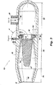
Fig. 2 is a partial sectional view ofFig. 1 , showing internal components of the fluid-gas mixer; -
Fig. 3 is side sectional view ofFig. 1 , showing the fluidic connections of the fluid-gas mixer; and -
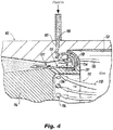
Fig. 4 , is a sectional view ofsection 4 ofFig. 3 , showing a detailed view of a mixing zone. - Reference will now be made to the drawings wherein like reference numerals identify similar structural features or aspects of the subject invention. For purposes of explanation and illustration, and not limitation, a partial view of an exemplary embodiment of a fluid-gas mixer in accordance with the invention is shown in
Fig. 1 and is designated generally byreference character 100. Other embodiments of the mixer in accordance with the invention, or aspects thereof, are provided inFigs. 2-4 , as will be described. The methods and systems of the invention can be used to improve aeration of fluids. - Referring to
Fig. 1 , a fluid-gas mixer 100 includes ahousing 102, defining aprimary axis 104, for mixing fluid and gas. Fluids intended for mixing include gaseous fuels (natural gas), as well as solid particles which have been fluidized such as flowing metal powder, and fluids such as liquid milk, liquid paint, water, oil, and various chemicals such as pesticides, herbicides. Thehousing 102 is elongated along theaxis 104, and includes at least a pair ofinlet conduits 107 108 for delivering the fluids to be mixed, and anoutlet 110. Agas conduit 107 can be connected to theinlet 106 of thehousing 102 for passing a gas to the housing. The gas can be air, oxygen, nitrogen, and other similar gasses. - Referring to
Figs. 2 and3 , amixer nozzle 112 circumscribing theprimary axis 104 is located within thehousing 102 and afluid conduit 108 is connected to themixer nozzle 112 for introducing a fluid to themixer nozzle 112. Thehousing 102 includes aninlet section 202, amixing section 204, and an outlet section 206. Astep 114 at theinner surface 124 of thehousing 102 forms a transition from theinlet section 202 to themixing section 204. Thestep 114 helps support themixer nozzle 112. Themixer nozzle 112 is u-shaped, with anapex 113 of themixer nozzle 112 directed towards an outlet of the housing. Themixer nozzle 112 includes acone 116 directed towards theoutlet 110 for controlling the recirculation of the mixed fluids. The cone includes arounded end 117, in order to produce the required flow pattern. Themixer nozzle 112 can use at least onestrut 118 to be fixed in position within thehousing 102. Threestruts 118 are the preferred, for supporting themixer nozzle 112 in multiple directions. Thehousing 102 includes a smooth widening section adjacent to thecone 116 for ensuring proper flow of the mixed fluids. Anannular gap 120 defines anouter gas path 126, the details of which are described below. - Referring to
Fig. 4 , the annular gap defined by anouter surface 122 of themixer nozzle 112 and aninner surface 124 of thehousing 102 defines at least oneouter gas path 126. Theouter gas path 126 narrows in the direction of flow. Theouter gas path 126 is annular and can be subdivided into discrete sections bystruts 118 attached to theinner surface 124 of thehousing 102 and theouter surface 122 of themixer nozzle 112. Thestruts 118 also provide support for themixer nozzle 112 within thehousing 102. Theouter gas path 126 area decreases in a downstream direction. Theouter gas path 126 can be narrowed by using theinner surface 124 of thehousing 102. The decreasing or narrowing area helps maintain a necessary energy to mix the fluids. One of thestruts 118 can include thefluid conduit 109 passing there through, Thefluid conduit 109 can be a pipe or flexible line, or can be negative space within thestrut 118. - Referring further to
Fig. 4 , thefluid conduit 109 is fluidly connected to anannular channel 130 within themixer nozzle 112. The mixer nozzle includes abody 132 circumscribing theprimary axis 104, aninlet 134 into theannular channel 130 within the body for receiving fluid, and at least one set ofpassages 136 directed radially and tangentially through thebody 132 and circumferentially distributed with respect to theprimary axis 104 and for passing fluid, specifically gas through thebody 132. Theannular channel 130 includes afluid outlet 135 adjacent to anoutlet 137 of the at least one set ofgas passages 136. The at least one set ofgas passages 136 can be a swirling gas passage defining aninner gas path 218 for injection of the gas and mixing with gasses coming through theouter gas path 126. The at least onegas passage 136 is also circumscribed around theprimary axis 104. Each of the passages partially circumscribes theprimary axis 104. It is also conceived that each of the passages can be fluidly connected to each other. - The
mixer nozzle 112, divides the gas flow through either theouter gas path 126 or theinner passage 136. The mixer nozzle divides the gas flow into two streams both between 40% and 60% of the total flow but preferably close to 50% each. The inner stream, through the at least onegas passage 136 is preferably given a tangential or swirling flow component of angular momentum, this swirling creates an axial velocity disparity. The narrowing cross section of theouter gas path 126 forces the flow to intersect with the flow of the inner stream. The flow of fluid from thefluid outlet 135 forms an annular film of the fluid and outputs the fluid centrally between the two gas streams. This arrangement improves the mixing of the fluid and gas. Thefluid outlet 135 is located between the inner and outer gas paths, and includes a larger diameter than the inner gas exit and at a smaller diameter than the outer gas exit. Theoutlet 110 provides further control of the operating pressure within the device and exit momentum of the flow. - The systems of the present disclosure, as described above and shown in the drawings, provide for a fluid mixing system with superior properties including increased reliability and reduced size, weight, complexity, and cost. While the apparatus and methods of the subject disclosure have been shown and described with reference to embodiments, those skilled in the art will readily appreciate that changes and/or modifications may be made thereto without departing from the spirit and scope of the subject disclosure.
Claims (15)
- A fluid-gas mixer (100) comprising:a housing (102), defining a primary axis, for mixing fluid and gas;a mixer nozzle (112) circumscribing the primary axis, wherein an annular gap (120) between an outer surface of the mixer nozzle (112) and an inner surface of the housing (102) defines at least one outer gas path (126);an inner gas passage defining an inner gas path for mixing with the outer gas path; anda fluid conduit (109) for supplying fluid to the mixer nozzle (112) configured to mix with the inner gas path and the outer gas path (126).
- The fluid mixer of claim 1, wherein the fluid conduit is fluidly connected to an annular channel within the mixer nozzle (112), the annular channel (120) including an outlet from the mixer nozzle parallel to the primary axis disposed between the inner gas path and the outer gas path.
- The fluid-gas mixer of claim 1 or 2, wherein the mixer nozzle (112) is u-shaped, with an apex of the mixer nozzle (112) directed towards an outlet of the housing (102).
- The fluid-gas mixer of any preceding claim, wherein the outer gas path area narrows in a downstream direction.
- The fluid gas mixer of any preceding claim, wherein the inner gas passage includes a swirling gas flow directed towards the annular gap (120)) between the interior surface of the housing (102) and the outer surface of the mixer nozzle (112).
- The fluid-gas mixer of any preceding claim, wherein the housing (102) includes an inlet section, a mixing section, and an outlet section.
- The fluid gas mixer of claim 6, wherein a step forms a transition from the inlet section to the mixing section, optionally wherein the step is upstream of a gas outlet.
- The fluid gas mixer of any preceding claim, wherein discrete struts (118) attached to an inner surface of the housing support the mixer nozzle (112) within the housing (102), optionally wherein at least one of the struts (118) includes the fluid conduit passing there through.
- The fluid-gas mixer of any preceding claim, wherein the mixer nozzle (112) includes a cone facing downstream for controlling recirculation zones.
- The fluid gas mixer of claim 9, wherein the housing (102) includes a smooth widening section adjacent to the cone (116).
- The fluid gas mixer of claim 9, wherein the cone (116) includes a rounded end.
- A fluid-gas mixer nozzle comprising:a body (132) circumscribing a primary axis;an inlet into an annular passage (120) within the body (132) for receiving fluid; andat least one passage through the body (132) directed radially and tangentially with respect to the primary axis for passing fluid through the body (132).
- The nozzle of claim 12, wherein the annular passage (120) includes an outlet adjacent to an outlet of the at least one passage.
- The nozzle of claim 12 orl3, wherein the body (132) includes a cone (116) directed away from the at least one passage.
- The nozzle of any of claims 12 to 14, wherein the body includes at least one supporting member, and wherein the at least one supporting member includes a fluid conduit (109) therein configured for passing fluid to the inlet of the annular passage (120).
Applications Claiming Priority (1)
| Application Number | Priority Date | Filing Date | Title |
|---|---|---|---|
| US16/387,153 US11014054B2 (en) | 2019-04-17 | 2019-04-17 | Fluid-gas mixer |
Publications (2)
| Publication Number | Publication Date |
|---|---|
| EP3725395A2 true EP3725395A2 (en) | 2020-10-21 |
| EP3725395A3 EP3725395A3 (en) | 2020-11-04 |
Family
ID=68655253
Family Applications (1)
| Application Number | Title | Priority Date | Filing Date |
|---|---|---|---|
| EP19210636.7A Withdrawn EP3725395A3 (en) | 2019-04-17 | 2019-11-21 | Fluid-gas mixer |
Country Status (2)
| Country | Link |
|---|---|
| US (1) | US11014054B2 (en) |
| EP (1) | EP3725395A3 (en) |
Cited By (2)
| Publication number | Priority date | Publication date | Assignee | Title |
|---|---|---|---|---|
| CN115159660A (en) * | 2022-07-20 | 2022-10-11 | 湖南中森环境科技有限公司 | Submersible jet ozone aerator |
| WO2025242541A1 (en) | 2024-05-21 | 2025-11-27 | Mme Engineering E.U. | Mixing system |
Families Citing this family (2)
| Publication number | Priority date | Publication date | Assignee | Title |
|---|---|---|---|---|
| KR102460672B1 (en) * | 2021-01-06 | 2022-10-27 | 두산에너빌리티 주식회사 | Fuel nozzle, fuel nozzle module and combustor having the same |
| DE102021001986A1 (en) * | 2021-04-15 | 2022-10-20 | Messer Austria Gmbh | Device and method for dispersing gases in liquids |
Family Cites Families (8)
| Publication number | Priority date | Publication date | Assignee | Title |
|---|---|---|---|---|
| US2398766A (en) | 1944-06-15 | 1946-04-23 | Bergesen Juneus | Steam injector for pipe lines |
| FR1491215A (en) | 1965-09-21 | 1967-08-11 | Bertin & Cie | Improvements to ejectors-mixers or tubes |
| US3741484A (en) * | 1970-09-30 | 1973-06-26 | Decafix Ltd | Atomisers |
| US4027858A (en) | 1976-06-29 | 1977-06-07 | The Dow Chemical Company | Apparatus for mixing |
| US6491064B2 (en) * | 2000-12-06 | 2002-12-10 | Juergen Kampe | Apparatus for charging a liquid medium with a gas |
| JP4065947B2 (en) | 2003-08-05 | 2008-03-26 | 独立行政法人 宇宙航空研究開発機構 | Fuel / air premixer for gas turbine combustor |
| EP1812150B1 (en) | 2004-10-01 | 2018-06-27 | Propure AS | Multi fluid injection mixer |
| US7926282B2 (en) | 2008-03-04 | 2011-04-19 | Delavan Inc | Pure air blast fuel injector |
-
2019
- 2019-04-17 US US16/387,153 patent/US11014054B2/en active Active
- 2019-11-21 EP EP19210636.7A patent/EP3725395A3/en not_active Withdrawn
Cited By (3)
| Publication number | Priority date | Publication date | Assignee | Title |
|---|---|---|---|---|
| CN115159660A (en) * | 2022-07-20 | 2022-10-11 | 湖南中森环境科技有限公司 | Submersible jet ozone aerator |
| CN115159660B (en) * | 2022-07-20 | 2023-09-19 | 湖南中森环境科技有限公司 | Submersible jet ozone aerator |
| WO2025242541A1 (en) | 2024-05-21 | 2025-11-27 | Mme Engineering E.U. | Mixing system |
Also Published As
| Publication number | Publication date |
|---|---|
| EP3725395A3 (en) | 2020-11-04 |
| US11014054B2 (en) | 2021-05-25 |
| US20200332998A1 (en) | 2020-10-22 |
Similar Documents
| Publication | Publication Date | Title |
|---|---|---|
| US11014054B2 (en) | Fluid-gas mixer | |
| US9016392B2 (en) | Fire suppression system with improved two-phase flow distribution | |
| JP6487041B2 (en) | Atomizer nozzle | |
| US8622715B1 (en) | Twin turbine asymmetrical nozzle and jet pump incorporating such nozzle | |
| US8512035B2 (en) | Mixing device for a gas burner | |
| US6811698B2 (en) | Method and apparatus for treating fluids | |
| JP6879571B6 (en) | Nozzles and methods for mixing fluid flows | |
| WO2009033000A1 (en) | Method of dynamic mixing of fluids | |
| JP2003530989A5 (en) | ||
| US20120228405A1 (en) | Liquid swirler flow control | |
| CN103573350A (en) | Mixing device for the aftertreatment of exhaust gases | |
| US20060035183A1 (en) | Mixer | |
| US6015100A (en) | Foam generating nozzle assembly with interchangeable nozzle tip | |
| US20120305272A1 (en) | Foam generating device for fire hoses | |
| US3531050A (en) | Two-phase homogenizer | |
| JP5540973B2 (en) | Fluid atomization nozzle, fluid atomization device | |
| JP6899631B2 (en) | Dispersion nozzle | |
| US20120308407A1 (en) | Dual injection airlift pump | |
| RU2636721C1 (en) | Nozzle with parabolic swirler | |
| CN111151150A (en) | Micro-power gas-liquid or liquid-liquid mixed nano-scale fluid generator | |
| CN204220331U (en) | Atomization jetting device | |
| RU2808326C1 (en) | Low-emission burner of combustion chamber of gas turbine power unit | |
| KR20250080486A (en) | Nozzle for spraying ulv and spraying apparatus using thereof | |
| KR20170005440A (en) | Injection device, in particular for injecting a hydrocarbon feedstock into a refining unit | |
| CN112423893A (en) | Counter-current mixer and atomizer |
Legal Events
| Date | Code | Title | Description |
|---|---|---|---|
| PUAI | Public reference made under article 153(3) epc to a published international application that has entered the european phase |
Free format text: ORIGINAL CODE: 0009012 |
|
| STAA | Information on the status of an ep patent application or granted ep patent |
Free format text: STATUS: THE APPLICATION HAS BEEN PUBLISHED |
|
| PUAL | Search report despatched |
Free format text: ORIGINAL CODE: 0009013 |
|
| AK | Designated contracting states |
Kind code of ref document: A2 Designated state(s): AL AT BE BG CH CY CZ DE DK EE ES FI FR GB GR HR HU IE IS IT LI LT LU LV MC MK MT NL NO PL PT RO RS SE SI SK SM TR |
|
| AX | Request for extension of the european patent |
Extension state: BA ME |
|
| RIC1 | Information provided on ipc code assigned before grant |
Ipc: B01F 3/04 20060101AFI20200922BHEP Ipc: B01F 5/04 20060101ALI20200922BHEP |
|
| AK | Designated contracting states |
Kind code of ref document: A3 Designated state(s): AL AT BE BG CH CY CZ DE DK EE ES FI FR GB GR HR HU IE IS IT LI LT LU LV MC MK MT NL NO PL PT RO RS SE SI SK SM TR |
|
| AX | Request for extension of the european patent |
Extension state: BA ME |
|
| RIC1 | Information provided on ipc code assigned before grant |
Ipc: B01F 5/04 20060101ALI20200925BHEP Ipc: B01F 3/04 20060101AFI20200925BHEP |
|
| STAA | Information on the status of an ep patent application or granted ep patent |
Free format text: STATUS: REQUEST FOR EXAMINATION WAS MADE |
|
| 17P | Request for examination filed |
Effective date: 20210504 |
|
| RBV | Designated contracting states (corrected) |
Designated state(s): AL AT BE BG CH CY CZ DE DK EE ES FI FR GB GR HR HU IE IS IT LI LT LU LV MC MK MT NL NO PL PT RO RS SE SI SK SM TR |
|
| STAA | Information on the status of an ep patent application or granted ep patent |
Free format text: STATUS: EXAMINATION IS IN PROGRESS |
|
| 17Q | First examination report despatched |
Effective date: 20211019 |
|
| RAP3 | Party data changed (applicant data changed or rights of an application transferred) |
Owner name: COLLINS ENGINE NOZZLES, INC. |
|
| P01 | Opt-out of the competence of the unified patent court (upc) registered |
Effective date: 20230922 |
|
| STAA | Information on the status of an ep patent application or granted ep patent |
Free format text: STATUS: THE APPLICATION HAS BEEN WITHDRAWN |
|
| 18W | Application withdrawn |
Effective date: 20240916 |