EP3725341A1 - Purge-free miniature rotary pump - Google Patents
Purge-free miniature rotary pump Download PDFInfo
- Publication number
- EP3725341A1 EP3725341A1 EP20174159.2A EP20174159A EP3725341A1 EP 3725341 A1 EP3725341 A1 EP 3725341A1 EP 20174159 A EP20174159 A EP 20174159A EP 3725341 A1 EP3725341 A1 EP 3725341A1
- Authority
- EP
- European Patent Office
- Prior art keywords
- housing
- rotor
- impeller
- drive unit
- pump
- Prior art date
- Legal status (The legal status is an assumption and is not a legal conclusion. Google has not performed a legal analysis and makes no representation as to the accuracy of the status listed.)
- Pending
Links
Images

Classifications
-
- A—HUMAN NECESSITIES
- A61—MEDICAL OR VETERINARY SCIENCE; HYGIENE
- A61M—DEVICES FOR INTRODUCING MEDIA INTO, OR ONTO, THE BODY; DEVICES FOR TRANSDUCING BODY MEDIA OR FOR TAKING MEDIA FROM THE BODY; DEVICES FOR PRODUCING OR ENDING SLEEP OR STUPOR
- A61M60/00—Blood pumps; Devices for mechanical circulatory actuation; Balloon pumps for circulatory assistance
- A61M60/10—Location thereof with respect to the patient's body
- A61M60/122—Implantable pumps or pumping devices, i.e. the blood being pumped inside the patient's body
- A61M60/126—Implantable pumps or pumping devices, i.e. the blood being pumped inside the patient's body implantable via, into, inside, in line, branching on, or around a blood vessel
- A61M60/148—Implantable pumps or pumping devices, i.e. the blood being pumped inside the patient's body implantable via, into, inside, in line, branching on, or around a blood vessel in line with a blood vessel using resection or like techniques, e.g. permanent endovascular heart assist devices
-
- F—MECHANICAL ENGINEERING; LIGHTING; HEATING; WEAPONS; BLASTING
- F04—POSITIVE - DISPLACEMENT MACHINES FOR LIQUIDS; PUMPS FOR LIQUIDS OR ELASTIC FLUIDS
- F04D—NON-POSITIVE-DISPLACEMENT PUMPS
- F04D13/00—Pumping installations or systems
- F04D13/02—Units comprising pumps and their driving means
- F04D13/06—Units comprising pumps and their driving means the pump being electrically driven
-
- A—HUMAN NECESSITIES
- A61—MEDICAL OR VETERINARY SCIENCE; HYGIENE
- A61M—DEVICES FOR INTRODUCING MEDIA INTO, OR ONTO, THE BODY; DEVICES FOR TRANSDUCING BODY MEDIA OR FOR TAKING MEDIA FROM THE BODY; DEVICES FOR PRODUCING OR ENDING SLEEP OR STUPOR
- A61M60/00—Blood pumps; Devices for mechanical circulatory actuation; Balloon pumps for circulatory assistance
- A61M60/10—Location thereof with respect to the patient's body
- A61M60/122—Implantable pumps or pumping devices, i.e. the blood being pumped inside the patient's body
- A61M60/126—Implantable pumps or pumping devices, i.e. the blood being pumped inside the patient's body implantable via, into, inside, in line, branching on, or around a blood vessel
- A61M60/13—Implantable pumps or pumping devices, i.e. the blood being pumped inside the patient's body implantable via, into, inside, in line, branching on, or around a blood vessel by means of a catheter allowing explantation, e.g. catheter pumps temporarily introduced via the vascular system
-
- A—HUMAN NECESSITIES
- A61—MEDICAL OR VETERINARY SCIENCE; HYGIENE
- A61M—DEVICES FOR INTRODUCING MEDIA INTO, OR ONTO, THE BODY; DEVICES FOR TRANSDUCING BODY MEDIA OR FOR TAKING MEDIA FROM THE BODY; DEVICES FOR PRODUCING OR ENDING SLEEP OR STUPOR
- A61M60/00—Blood pumps; Devices for mechanical circulatory actuation; Balloon pumps for circulatory assistance
- A61M60/10—Location thereof with respect to the patient's body
- A61M60/122—Implantable pumps or pumping devices, i.e. the blood being pumped inside the patient's body
- A61M60/165—Implantable pumps or pumping devices, i.e. the blood being pumped inside the patient's body implantable in, on, or around the heart
-
- A—HUMAN NECESSITIES
- A61—MEDICAL OR VETERINARY SCIENCE; HYGIENE
- A61M—DEVICES FOR INTRODUCING MEDIA INTO, OR ONTO, THE BODY; DEVICES FOR TRANSDUCING BODY MEDIA OR FOR TAKING MEDIA FROM THE BODY; DEVICES FOR PRODUCING OR ENDING SLEEP OR STUPOR
- A61M60/00—Blood pumps; Devices for mechanical circulatory actuation; Balloon pumps for circulatory assistance
- A61M60/10—Location thereof with respect to the patient's body
- A61M60/122—Implantable pumps or pumping devices, i.e. the blood being pumped inside the patient's body
- A61M60/165—Implantable pumps or pumping devices, i.e. the blood being pumped inside the patient's body implantable in, on, or around the heart
- A61M60/178—Implantable pumps or pumping devices, i.e. the blood being pumped inside the patient's body implantable in, on, or around the heart drawing blood from a ventricle and returning the blood to the arterial system via a cannula external to the ventricle, e.g. left or right ventricular assist devices
-
- A—HUMAN NECESSITIES
- A61—MEDICAL OR VETERINARY SCIENCE; HYGIENE
- A61M—DEVICES FOR INTRODUCING MEDIA INTO, OR ONTO, THE BODY; DEVICES FOR TRANSDUCING BODY MEDIA OR FOR TAKING MEDIA FROM THE BODY; DEVICES FOR PRODUCING OR ENDING SLEEP OR STUPOR
- A61M60/00—Blood pumps; Devices for mechanical circulatory actuation; Balloon pumps for circulatory assistance
- A61M60/20—Type thereof
- A61M60/205—Non-positive displacement blood pumps
- A61M60/216—Non-positive displacement blood pumps including a rotating member acting on the blood, e.g. impeller
- A61M60/237—Non-positive displacement blood pumps including a rotating member acting on the blood, e.g. impeller the blood flow through the rotating member having mainly axial components, e.g. axial flow pumps
-
- A—HUMAN NECESSITIES
- A61—MEDICAL OR VETERINARY SCIENCE; HYGIENE
- A61M—DEVICES FOR INTRODUCING MEDIA INTO, OR ONTO, THE BODY; DEVICES FOR TRANSDUCING BODY MEDIA OR FOR TAKING MEDIA FROM THE BODY; DEVICES FOR PRODUCING OR ENDING SLEEP OR STUPOR
- A61M60/00—Blood pumps; Devices for mechanical circulatory actuation; Balloon pumps for circulatory assistance
- A61M60/20—Type thereof
- A61M60/205—Non-positive displacement blood pumps
- A61M60/216—Non-positive displacement blood pumps including a rotating member acting on the blood, e.g. impeller
- A61M60/237—Non-positive displacement blood pumps including a rotating member acting on the blood, e.g. impeller the blood flow through the rotating member having mainly axial components, e.g. axial flow pumps
- A61M60/242—Non-positive displacement blood pumps including a rotating member acting on the blood, e.g. impeller the blood flow through the rotating member having mainly axial components, e.g. axial flow pumps with the outlet substantially perpendicular to the axis of rotation
-
- A—HUMAN NECESSITIES
- A61—MEDICAL OR VETERINARY SCIENCE; HYGIENE
- A61M—DEVICES FOR INTRODUCING MEDIA INTO, OR ONTO, THE BODY; DEVICES FOR TRANSDUCING BODY MEDIA OR FOR TAKING MEDIA FROM THE BODY; DEVICES FOR PRODUCING OR ENDING SLEEP OR STUPOR
- A61M60/00—Blood pumps; Devices for mechanical circulatory actuation; Balloon pumps for circulatory assistance
- A61M60/40—Details relating to driving
- A61M60/403—Details relating to driving for non-positive displacement blood pumps
- A61M60/408—Details relating to driving for non-positive displacement blood pumps the force acting on the blood contacting member being mechanical, e.g. transmitted by a shaft or cable
- A61M60/411—Details relating to driving for non-positive displacement blood pumps the force acting on the blood contacting member being mechanical, e.g. transmitted by a shaft or cable generated by an electromotor
- A61M60/416—Details relating to driving for non-positive displacement blood pumps the force acting on the blood contacting member being mechanical, e.g. transmitted by a shaft or cable generated by an electromotor transmitted directly by the motor rotor drive shaft
-
- A—HUMAN NECESSITIES
- A61—MEDICAL OR VETERINARY SCIENCE; HYGIENE
- A61M—DEVICES FOR INTRODUCING MEDIA INTO, OR ONTO, THE BODY; DEVICES FOR TRANSDUCING BODY MEDIA OR FOR TAKING MEDIA FROM THE BODY; DEVICES FOR PRODUCING OR ENDING SLEEP OR STUPOR
- A61M60/00—Blood pumps; Devices for mechanical circulatory actuation; Balloon pumps for circulatory assistance
- A61M60/40—Details relating to driving
- A61M60/403—Details relating to driving for non-positive displacement blood pumps
- A61M60/422—Details relating to driving for non-positive displacement blood pumps the force acting on the blood contacting member being electromagnetic, e.g. using canned motor pumps
-
- A—HUMAN NECESSITIES
- A61—MEDICAL OR VETERINARY SCIENCE; HYGIENE
- A61M—DEVICES FOR INTRODUCING MEDIA INTO, OR ONTO, THE BODY; DEVICES FOR TRANSDUCING BODY MEDIA OR FOR TAKING MEDIA FROM THE BODY; DEVICES FOR PRODUCING OR ENDING SLEEP OR STUPOR
- A61M60/00—Blood pumps; Devices for mechanical circulatory actuation; Balloon pumps for circulatory assistance
- A61M60/50—Details relating to control
- A61M60/508—Electronic control means, e.g. for feedback regulation
- A61M60/515—Regulation using real-time patient data
- A61M60/531—Regulation using real-time patient data using blood pressure data, e.g. from blood pressure sensors
-
- A—HUMAN NECESSITIES
- A61—MEDICAL OR VETERINARY SCIENCE; HYGIENE
- A61M—DEVICES FOR INTRODUCING MEDIA INTO, OR ONTO, THE BODY; DEVICES FOR TRANSDUCING BODY MEDIA OR FOR TAKING MEDIA FROM THE BODY; DEVICES FOR PRODUCING OR ENDING SLEEP OR STUPOR
- A61M60/00—Blood pumps; Devices for mechanical circulatory actuation; Balloon pumps for circulatory assistance
- A61M60/80—Constructional details other than related to driving
- A61M60/802—Constructional details other than related to driving of non-positive displacement blood pumps
- A61M60/81—Pump housings
- A61M60/816—Sensors arranged on or in the housing, e.g. ultrasonic flow sensors
-
- A—HUMAN NECESSITIES
- A61—MEDICAL OR VETERINARY SCIENCE; HYGIENE
- A61M—DEVICES FOR INTRODUCING MEDIA INTO, OR ONTO, THE BODY; DEVICES FOR TRANSDUCING BODY MEDIA OR FOR TAKING MEDIA FROM THE BODY; DEVICES FOR PRODUCING OR ENDING SLEEP OR STUPOR
- A61M60/00—Blood pumps; Devices for mechanical circulatory actuation; Balloon pumps for circulatory assistance
- A61M60/80—Constructional details other than related to driving
- A61M60/802—Constructional details other than related to driving of non-positive displacement blood pumps
- A61M60/818—Bearings
- A61M60/82—Magnetic bearings
- A61M60/822—Magnetic bearings specially adapted for being actively controlled
-
- A—HUMAN NECESSITIES
- A61—MEDICAL OR VETERINARY SCIENCE; HYGIENE
- A61M—DEVICES FOR INTRODUCING MEDIA INTO, OR ONTO, THE BODY; DEVICES FOR TRANSDUCING BODY MEDIA OR FOR TAKING MEDIA FROM THE BODY; DEVICES FOR PRODUCING OR ENDING SLEEP OR STUPOR
- A61M60/00—Blood pumps; Devices for mechanical circulatory actuation; Balloon pumps for circulatory assistance
- A61M60/80—Constructional details other than related to driving
- A61M60/802—Constructional details other than related to driving of non-positive displacement blood pumps
- A61M60/818—Bearings
- A61M60/825—Contact bearings, e.g. ball-and-cup or pivot bearings
-
- F—MECHANICAL ENGINEERING; LIGHTING; HEATING; WEAPONS; BLASTING
- F04—POSITIVE - DISPLACEMENT MACHINES FOR LIQUIDS; PUMPS FOR LIQUIDS OR ELASTIC FLUIDS
- F04D—NON-POSITIVE-DISPLACEMENT PUMPS
- F04D29/00—Details, component parts, or accessories
- F04D29/04—Shafts or bearings, or assemblies thereof
- F04D29/046—Bearings
- F04D29/048—Bearings magnetic; electromagnetic
-
- F—MECHANICAL ENGINEERING; LIGHTING; HEATING; WEAPONS; BLASTING
- F04—POSITIVE - DISPLACEMENT MACHINES FOR LIQUIDS; PUMPS FOR LIQUIDS OR ELASTIC FLUIDS
- F04D—NON-POSITIVE-DISPLACEMENT PUMPS
- F04D29/00—Details, component parts, or accessories
- F04D29/18—Rotors
-
- F—MECHANICAL ENGINEERING; LIGHTING; HEATING; WEAPONS; BLASTING
- F04—POSITIVE - DISPLACEMENT MACHINES FOR LIQUIDS; PUMPS FOR LIQUIDS OR ELASTIC FLUIDS
- F04D—NON-POSITIVE-DISPLACEMENT PUMPS
- F04D29/00—Details, component parts, or accessories
- F04D29/40—Casings; Connections of working fluid
- F04D29/406—Casings; Connections of working fluid especially adapted for liquid pumps
-
- A—HUMAN NECESSITIES
- A61—MEDICAL OR VETERINARY SCIENCE; HYGIENE
- A61M—DEVICES FOR INTRODUCING MEDIA INTO, OR ONTO, THE BODY; DEVICES FOR TRANSDUCING BODY MEDIA OR FOR TAKING MEDIA FROM THE BODY; DEVICES FOR PRODUCING OR ENDING SLEEP OR STUPOR
- A61M60/00—Blood pumps; Devices for mechanical circulatory actuation; Balloon pumps for circulatory assistance
- A61M60/10—Location thereof with respect to the patient's body
- A61M60/122—Implantable pumps or pumping devices, i.e. the blood being pumped inside the patient's body
- A61M60/126—Implantable pumps or pumping devices, i.e. the blood being pumped inside the patient's body implantable via, into, inside, in line, branching on, or around a blood vessel
- A61M60/135—Implantable pumps or pumping devices, i.e. the blood being pumped inside the patient's body implantable via, into, inside, in line, branching on, or around a blood vessel inside a blood vessel, e.g. using grafting
-
- A—HUMAN NECESSITIES
- A61—MEDICAL OR VETERINARY SCIENCE; HYGIENE
- A61M—DEVICES FOR INTRODUCING MEDIA INTO, OR ONTO, THE BODY; DEVICES FOR TRANSDUCING BODY MEDIA OR FOR TAKING MEDIA FROM THE BODY; DEVICES FOR PRODUCING OR ENDING SLEEP OR STUPOR
- A61M60/00—Blood pumps; Devices for mechanical circulatory actuation; Balloon pumps for circulatory assistance
- A61M60/80—Constructional details other than related to driving
- A61M60/802—Constructional details other than related to driving of non-positive displacement blood pumps
- A61M60/818—Bearings
- A61M60/82—Magnetic bearings
-
- A—HUMAN NECESSITIES
- A61—MEDICAL OR VETERINARY SCIENCE; HYGIENE
- A61M—DEVICES FOR INTRODUCING MEDIA INTO, OR ONTO, THE BODY; DEVICES FOR TRANSDUCING BODY MEDIA OR FOR TAKING MEDIA FROM THE BODY; DEVICES FOR PRODUCING OR ENDING SLEEP OR STUPOR
- A61M60/00—Blood pumps; Devices for mechanical circulatory actuation; Balloon pumps for circulatory assistance
- A61M60/80—Constructional details other than related to driving
- A61M60/802—Constructional details other than related to driving of non-positive displacement blood pumps
- A61M60/818—Bearings
- A61M60/824—Hydrodynamic or fluid film bearings
-
- A—HUMAN NECESSITIES
- A61—MEDICAL OR VETERINARY SCIENCE; HYGIENE
- A61M—DEVICES FOR INTRODUCING MEDIA INTO, OR ONTO, THE BODY; DEVICES FOR TRANSDUCING BODY MEDIA OR FOR TAKING MEDIA FROM THE BODY; DEVICES FOR PRODUCING OR ENDING SLEEP OR STUPOR
- A61M60/00—Blood pumps; Devices for mechanical circulatory actuation; Balloon pumps for circulatory assistance
- A61M60/80—Constructional details other than related to driving
- A61M60/802—Constructional details other than related to driving of non-positive displacement blood pumps
- A61M60/827—Sealings between moving parts
- A61M60/829—Sealings between moving parts having a purge fluid supply
- A61M60/831—Sealings between moving parts having a purge fluid supply using filtered blood as purge fluid
Definitions
- Embodiments of this invention relate generally to, but are not limited to, the provision and use of medical devices and, more particularly, to the provision and use of miniature, implantable blood pumps for assisting or supplementing cardiac function.
- At least some aspects and embodiments of the invention are directed to systems and methods for assisting the functioning of the human heart.
- one embodiment is directed to a system and method for pumping blood that utilizes a miniature blood pump with a tubular housing including a drive unit carrying an impeller, where the drive unit is maintained free of clots or other blood deposits without the use of a purge fluid.
- a blood pump that may comprise a tubular housing in which an electromotive drive unit is located.
- the drive unit may be arranged coaxially within the housing, creating a primary blood flow channel in the annular space between the drive unit and the interior surface of the housing.
- blood is driven in a generally helical motion by an impeller arranged on the upstream side of the drive unit, circulates along the flow channel, and exits the housing through a laterally branching outlet tube.
- the housing and the outlet tube may have an L-shaped configuration, whereby the pump may be inserted into a port created in the cardiac wall, while the outlet tube may be connected to a target vessel.
- the blood pump may serve to support the heart temporarily without being totally inserted into the heart like larger, intracardiac blood pumps.
- the blood pump may include an annular, secondary flow channel constructed between the rotor and the stator, through which blood flows to continually flush the areas between the relatively moving parts of the rotor and stator.
- the secondary blood flow may be in a direction generally opposite the primary blood flow.
- Another aspect of the invention is directed to a miniature axial blood pump in which a rotor carrying an impeller does not require mechanical support in the axial direction.
- the blood pump may employ a magnetic bearing that supports the rotor and impeller in the axial direction.
- the axial magnetic bearing may be at least partially active.
- Another aspect of the invention provides a catheter-based pump that employs the purge fluid free secondary blood flow path arrangement described above.
- the primary blood flow is directed outside and around the housing immediately behind the impeller, and additional ports positioned behind the rotor allow for the intake of blood to form the secondary blood flow.
- Another aspect of the invention may provide for a catheter-based pump that employs a magnetic bearing to control the axial position of a rotor carrying an impeller.
- the magnetic bearing may be active, or passive, or both.
- Another aspect of the invention is directed to method for providing cardiac assistance by the use of a miniature blood pump that includes a housing, a drive unit positioned within the housing and having a rotor and a stator, an impeller positioned at one end of the drive unit and connected to the rotor, and a cannula extending from the end of the housing nearest the impeller.
- the pump may be operated to create a primary blood flow around the drive unit and a secondary blood flow in an annular space formed between the rotor and the stator.
- the secondary blood flow may be generally in a direction opposite the primary blood flow.
- Axial support may be provided by mechanical bearings and/or by active or passive magnetic bearings.
- a blood pump according to one embodiment of the invention is shown in schematic cross section in FIG. 1 .
- the blood pump 100 of this illustrative embodiment has an elongated, substantially cylindrical housing 200 in which a drive unit 210 is generally co-axially positioned.
- the drive unit 210 includes an electric motor comprising a stator portion 300 and a rotor portion 400. Electrical conductors 220 passing through a catheter 230 provide power and control signals to the electric motor.
- the annular space between the drive unit 210 and the interior of the housing forms the primary blood flow path 240.
- the inner and outer diameters of the primary blood flow path may be on the order of 7.0 and 10.0 mm, respectively, providing for a cross-sectional area in the primary blood flow path of approximately 160 mm 2 .
- the stator portion 300 comprises a pair of permanent stator bearing magnets 310a, 310b.
- One stator bearing magnet 310a is positioned near the upstream end of the stator, while the other stator bearing magnet 310b is fixed near the downstream end.
- the stator bearing magnets 310a, 310b cooperate with permanent rotor bearing magnets 410a, 410b to form a pair of radial magnetic bearings.
- the radial bearings allow the rotor to rotate relative to the stator without significant radial contact and create an annular space to allow for a secondary blood flow path 255.
- the stator bearing magnets 310a, 310b and rotor bearing magnets 410a, 410b may be comprised of stacked thin disc magnets, tubular magnets with an axial magnetization, or any other appropriate magnetic arrangement.
- the inner and outer diameters of the secondary blood flow path 255 may be on the order of 3.2 and 3.8 mm, respectively, providing a cross-sectional area of approximately 3.3 mm 2 .
- stator motor magnet 320 Located on the stator portion 300 between the stator bearing magnets 310a, 310b is a stator motor magnet 320.
- the stator motor magnet 320 combines with a rotor motor magnet 420 to form an electromagnetic motor that may be driven by conventional means to cause rotation of the rotor 400.
- an impeller 500 is attached to the rotor 400.
- the impeller 500 includes a hub 510 and a plurality of vanes 520 that project from the hub 510.
- the vanes may take any appropriate shape and be of any appropriate number.
- the impeller 500 rotates in a cylindrical pump ring 530, the diameter of which is about the same as that of the envelope of the impeller 500.
- the upstream end of the pump ring 530 has an axial inlet 540 that includes an input bevel 545.
- the downstream end of the pump ring 530 is followed by an impeller-free transition region 550, within which the inside diameter continuously enlarges from that of the pump ring 530 to that of the inner diameter of the housing 200 surrounding the drive unit 210.
- an axial hydraulic bearing 260 may be positioned at the end of the rotor 400 that includes the impeller 500.
- the axial hydraulic bearing 260 serves to arrest the forward translation of the rotor 400.
- the axial hydraulic bearing 260 is provided with a plurality of openings that allow blood to pass though the bearing.
- the axial bearing may also be configured as a contact bearing, so as to physically arrest forward movement of the rotor 400, particularly where external forces are operating on the device or when the rotor is starting up or winding down.
- the axial position of the rotor 400 may be controlled by an axial magnetic bearing positioned at either end of the rotor, with or without the additional use of a mechanical contact bearing.
- the axial magnetic bearing may comprise a permanent axial housing magnet 270, positioned in the housing 200 near the end of the rotor 400 opposite the impeller 500, and cooperating with a permanent axial rotor magnet 410, positioned in the end of the rotor opposite the impeller 500.
- the axial bearing may include an active magnetic bearing that operates alone or in conjunction with the passive magnetic bearing and/or mechanical contact bearing.
- the axial magnetic bearing comprises a cylindrical passive magnet designed to counteract the axial forces encountered when the rotor 400 is up to speed, surrounded by an active magnet, designed to compensate for additional axial loads, such as those present during pre-load or after-load of the impeller.
- the axial position of the impeller may be determined by measuring the back emf within the system, thus eliminating the need for an additional position sensor.
- a separate position sensor may be employed to provide feedback concerning the position of the rotor and facilitate control by an active magnetic bearing.
- an outlet tube 600 laterally branches from the pump housing 200. This outlet tube 600 extends in a direction generally perpendicular to the flow channel 240. In some embodiments, the inner diameter of the outlet tube 600 may enlarge in the direction of flow. The enlargement may be on the order or 5-10 degrees or, in one particular embodiment, approximately 8 degrees.
- a pressure detection opening in the inner wall of the housing that communicates with the primary flow channel 240. From the pressure detection opening, a pressure channel may be in fluid communication with the lumen of a hose extending through the catheter 230.
- a pressure sensor may be connected at the proximal end of the catheter to detect the pressure at the place of the pressure detection opening within the primary flow channel 240.
- a local pressure sensor can be installed within the blood pump 100.
- a tubular cannula 700 may be mounted on the pump ring 530 and extend from the housing 200.
- the cannula 700 may have longitudinally extending slots 710 arranged about its periphery, and/or an axial opening 720 at the front end.
- the length of the cannula 700 may, in some cases, not exceed the length of the housing 200, including the pump ring 530.
- the outer diameter of the housing 200 is approximately 11 mm.
- the inner diameter of the housing in the region of the flow channel 240 is approximately 10 mm.
- the drive unit 210 has an outside diameter of approximately 7.0 mm.
- the inner diameter of the pump ring 530 is approximately 6 mm, the outer diameter of the cannula 700 is approximately 10 mm, and the inner diameter of the cannula 700 is approximately to 8 mm.
- the entire housing 200 including the pump ring 530, has a length of about 50 mm, and the portion of the cannula 700 projecting beyond the pump ring 530 has a length of about 35 mm.
- the dimensions of this particular embodiment are expected to result in blood flow rates of from 1.5 to 3.0 m/s in the region of the pump ring 530, from 1.0 to 1.5 m/s in the region of the flow channel 240, and of 0.5 m/s in the region of the outlet tube 600.
- the drive unit 210 is configured to run at a relatively high rotational speed of from 10,000 to 33,000 rpm. At those speeds, the impeller 500 would move in the range of 4 to 6 1 (liters) of blood per minute under physiological pressure conditions.
- exemplary device of FIG. 1 would, with the above dimensions, result in a flow rate in the secondary blood flow path 255 greater than approximately 20 ml/min, with a shear rate of less than 150 N/m 2 , a transition time of less than approximately 200 ms, and that it would maintain the inner surfaces of the motor at or below approximately 44°C.
- the pressure differential between the secondary flow path and the primary flow path should be no less than approximately 60 mmHg.
- the desired pressure differential is achieved by use of the laterally branching outlet tube 600, described above, which creates a secondary pressure rise.
- the secondary flow path 255 can be connected to the primary flow channel by means of a small gap 560 positioned behind the impeller 500 and running in a direction approximately perpendicular to the direction of flow through the primary flow channel. This gap 560 can help create a "water pump" effect that reduces the pressure within the secondary flow path 255 and helps to draw blood through the secondary flow path 255 in a direction opposite the flow through the primary flow path 240.
- the exemplar paracardiac blood pump of FIG. 1 may be inserted though a puncture in the cardiac wall and introduced into the heart in such a manner that the housing 200 sealingly closes the puncture hole, while the cannula 700 is in the interior of the heart and the outlet tube 600 outside the heart.
- the puncture hole in the cardiac wall may be made without removing cardiac wall tissue. This facilitates the closing of the hole in the cardiac wall after the future withdrawal of the pump.
- a peripheral enlargement 290 may be provided on the housing 200.
- an essential portion of the length of the housing 200 and the cannula 700 is located in the interior of the heart, while a relatively short portion of the housing 200 projects from the heart, and the outlet tube 600 together with a hose connected to the outlet tube 600 lies close against the outside of the heart. Therefore, the blood pump does not occupy substantial room within the chest cavity.
- the blood pump may be implanted into the open heart to provide heart support for the duration of an operation or another intervention or to provide longer term support following an operation.
- An advantage of a miniature pump is that no heavyweight and voluminous pumps need to be borne on the thoracic region of the patient.
- the pump is so small and light that even the fragile right or left atrium is not substantially deformed by applying and introducing the pump. In all cases, the positioning of the pump may be effected in a space-saving manner, and disturbances and impairments of the access to the heart being kept as low as possible.
- a catheter-based pump includes a housing 200 that carries a stator motor magnet 320 and stator bearing magnets 310a, 310b.
- a rotor 400 carries a rotor motor magnet 420, rotor bearing magnets 410a, 410b, and an impeller 500.
- the rotor and stator bearing magnets cooperate to form forward and rear radial magnetic bearings.
- the rotating impeller creates a primary blood flow that passes outside the housing through primary blood flow openings 245.
- Secondary blood flow openings 285, located downstream of the primary blood flow openings 245 allow for a secondary blood flow path 255 between the rotor 400 and the housing 200 including the stator magnets. As in the embodiment of FIG. 1 , this secondary blood flow path 255 is generally in a direction opposite the primary blood flow path. The flow of blood through the secondary blood flow path 255 serves to prevent the accumulation of clots or other blood deposits within the motor.
- an axial magnetic bearing which may be passive, active, or both, may be located at the rear of the rotor and counteracts the forces drawing the rotor forward, as described above.
- the axial forces may be addressed hydraulic or contact bearings.
Landscapes
- Health & Medical Sciences (AREA)
- Engineering & Computer Science (AREA)
- Heart & Thoracic Surgery (AREA)
- Mechanical Engineering (AREA)
- Cardiology (AREA)
- General Health & Medical Sciences (AREA)
- Veterinary Medicine (AREA)
- Hematology (AREA)
- Life Sciences & Earth Sciences (AREA)
- Animal Behavior & Ethology (AREA)
- Anesthesiology (AREA)
- Public Health (AREA)
- Biomedical Technology (AREA)
- General Engineering & Computer Science (AREA)
- Vascular Medicine (AREA)
- Physics & Mathematics (AREA)
- Electromagnetism (AREA)
- Medical Informatics (AREA)
- External Artificial Organs (AREA)
- Structures Of Non-Positive Displacement Pumps (AREA)
Abstract
Description
- Embodiments of this invention relate generally to, but are not limited to, the provision and use of medical devices and, more particularly, to the provision and use of miniature, implantable blood pumps for assisting or supplementing cardiac function.
- At least some aspects and embodiments of the invention are directed to systems and methods for assisting the functioning of the human heart. In particular, one embodiment is directed to a system and method for pumping blood that utilizes a miniature blood pump with a tubular housing including a drive unit carrying an impeller, where the drive unit is maintained free of clots or other blood deposits without the use of a purge fluid.
- Existing miniature blood pumps, such as that of
U.S. Patent No. 6,942,611 , employ a purge fluid to maintain the motor section free of obstructions that could impair performance or, in the long term, cause seizure of the pump. While the purge fluid arrangement is relatively effective, the additional structure it requires may increase the risk of pump failure when the device is used for longer durations, such as those in excess of thirty days. - One embodiment in accord with the present invention includes a blood pump that may comprise a tubular housing in which an electromotive drive unit is located. The drive unit may be arranged coaxially within the housing, creating a primary blood flow channel in the annular space between the drive unit and the interior surface of the housing. In this configuration, blood is driven in a generally helical motion by an impeller arranged on the upstream side of the drive unit, circulates along the flow channel, and exits the housing through a laterally branching outlet tube.
- The housing and the outlet tube may have an L-shaped configuration, whereby the pump may be inserted into a port created in the cardiac wall, while the outlet tube may be connected to a target vessel. In this configuration, the blood pump may serve to support the heart temporarily without being totally inserted into the heart like larger, intracardiac blood pumps.
- One aspect of the invention is directed to a miniature blood pump that is maintained free of clots or other blood deposits or accumulations without the use of a purge fluid. The blood pump may include an annular, secondary flow channel constructed between the rotor and the stator, through which blood flows to continually flush the areas between the relatively moving parts of the rotor and stator. The secondary blood flow may be in a direction generally opposite the primary blood flow.
- Another aspect of the invention is directed to a miniature axial blood pump in which a rotor carrying an impeller does not require mechanical support in the axial direction. The blood pump may employ a magnetic bearing that supports the rotor and impeller in the axial direction. In some embodiments, the axial magnetic bearing may be at least partially active.
- Another aspect of the invention provides a catheter-based pump that employs the purge fluid free secondary blood flow path arrangement described above. In this device, the primary blood flow is directed outside and around the housing immediately behind the impeller, and additional ports positioned behind the rotor allow for the intake of blood to form the secondary blood flow.
- Another aspect of the invention may provide for a catheter-based pump that employs a magnetic bearing to control the axial position of a rotor carrying an impeller. The magnetic bearing may be active, or passive, or both.
- Another aspect of the invention is directed to method for providing cardiac assistance by the use of a miniature blood pump that includes a housing, a drive unit positioned within the housing and having a rotor and a stator, an impeller positioned at one end of the drive unit and connected to the rotor, and a cannula extending from the end of the housing nearest the impeller. The pump may be operated to create a primary blood flow around the drive unit and a secondary blood flow in an annular space formed between the rotor and the stator. The secondary blood flow may be generally in a direction opposite the primary blood flow. Axial support may be provided by mechanical bearings and/or by active or passive magnetic bearings.
- The accompanying drawings are not intended to be drawn to scale. In the drawings, each identical or nearly identical component that is illustrated in various figures is represented by a like numeral. For purposes of clarity, not every component may be labeled in every drawing. In the drawings:
-
FIG. 1 is a schematic cross-section of one embodiment of a blood pump according to the present invention; and -
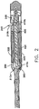
FIG. 2 is a schematic cross-section of one embodiment of a catheter-based blood pump according to the present invention. - Various embodiments and aspects thereof will now be described in more detail with reference to the accompanying figures. It is to be appreciated that this invention is not limited in its application to the details of construction and the arrangement of components set forth in the following description or illustrated in the drawings. The invention is capable of other embodiments and of being practiced or of being carried out in various ways. Examples of specific implementations are provided herein for illustrative purposes only and are not intended to be limiting. In particular, acts, elements and features discussed in connection with any one or more embodiments are not intended to be excluded from a similar role in any other embodiments. Also, the phraseology and terminology used herein is for the purpose of description and should not be regarded as limiting. The use of "including," "comprising," "having," "containing," "involving," and variations thereof is meant to encompass the items listed thereafter and equivalents thereof as well as additional items.
- A blood pump according to one embodiment of the invention is shown in schematic cross section in
FIG. 1 . - The
blood pump 100 of this illustrative embodiment has an elongated, substantiallycylindrical housing 200 in which adrive unit 210 is generally co-axially positioned. Thedrive unit 210 includes an electric motor comprising astator portion 300 and arotor portion 400.Electrical conductors 220 passing through acatheter 230 provide power and control signals to the electric motor. - The annular space between the
drive unit 210 and the interior of the housing forms the primaryblood flow path 240. In one embodiment, the inner and outer diameters of the primary blood flow path may be on the order of 7.0 and 10.0 mm, respectively, providing for a cross-sectional area in the primary blood flow path of approximately 160 mm2. - The
stator portion 300 comprises a pair of permanentstator bearing magnets stator bearing magnet 310a is positioned near the upstream end of the stator, while the other stator bearingmagnet 310b is fixed near the downstream end. - The stator bearing
magnets magnets blood flow path 255. The stator bearingmagnets rotor bearing magnets - In the illustrative embodiment, the inner and outer diameters of the secondary
blood flow path 255 may be on the order of 3.2 and 3.8 mm, respectively, providing a cross-sectional area of approximately 3.3 mm2. - Located on the
stator portion 300 between thestator bearing magnets stator motor magnet 320. Thestator motor magnet 320 combines with arotor motor magnet 420 to form an electromagnetic motor that may be driven by conventional means to cause rotation of therotor 400. - In this embodiment, an
impeller 500 is attached to therotor 400. Theimpeller 500 includes ahub 510 and a plurality ofvanes 520 that project from thehub 510. The vanes may take any appropriate shape and be of any appropriate number. Theimpeller 500 rotates in acylindrical pump ring 530, the diameter of which is about the same as that of the envelope of theimpeller 500. The upstream end of thepump ring 530 has anaxial inlet 540 that includes aninput bevel 545. The downstream end of thepump ring 530 is followed by an impeller-free transition region 550, within which the inside diameter continuously enlarges from that of thepump ring 530 to that of the inner diameter of thehousing 200 surrounding thedrive unit 210. - The operation of the
rotor 400 creates a force that draws the rotor forward, i.e., in the direction opposite the blood flow. To prevent therotor 400 from being drawn so far forward that it contacts the housing, an axialhydraulic bearing 260 may be positioned at the end of therotor 400 that includes theimpeller 500. The axial hydraulic bearing 260 serves to arrest the forward translation of therotor 400. In this embodiment, the axial hydraulic bearing 260 is provided with a plurality of openings that allow blood to pass though the bearing. In some embodiments, the axial bearing may also be configured as a contact bearing, so as to physically arrest forward movement of therotor 400, particularly where external forces are operating on the device or when the rotor is starting up or winding down. - In some embodiments, the axial position of the
rotor 400 may be controlled by an axial magnetic bearing positioned at either end of the rotor, with or without the additional use of a mechanical contact bearing. In one embodiment, for example, the axial magnetic bearing may comprise a permanentaxial housing magnet 270, positioned in thehousing 200 near the end of therotor 400 opposite theimpeller 500, and cooperating with a permanentaxial rotor magnet 410, positioned in the end of the rotor opposite theimpeller 500. In another embodiment, the axial bearing may include an active magnetic bearing that operates alone or in conjunction with the passive magnetic bearing and/or mechanical contact bearing. In one embodiment, the axial magnetic bearing comprises a cylindrical passive magnet designed to counteract the axial forces encountered when therotor 400 is up to speed, surrounded by an active magnet, designed to compensate for additional axial loads, such as those present during pre-load or after-load of the impeller. In some cases, the axial position of the impeller may be determined by measuring the back emf within the system, thus eliminating the need for an additional position sensor. In other cases, a separate position sensor may be employed to provide feedback concerning the position of the rotor and facilitate control by an active magnetic bearing. - Towards the downstream end of the
flow channel 240, anoutlet tube 600 laterally branches from thepump housing 200. Thisoutlet tube 600 extends in a direction generally perpendicular to theflow channel 240. In some embodiments, the inner diameter of theoutlet tube 600 may enlarge in the direction of flow. The enlargement may be on the order or 5-10 degrees or, in one particular embodiment, approximately 8 degrees. - In certain embodiments, there may be a pressure detection opening in the inner wall of the housing that communicates with the
primary flow channel 240. From the pressure detection opening, a pressure channel may be in fluid communication with the lumen of a hose extending through thecatheter 230. A pressure sensor may be connected at the proximal end of the catheter to detect the pressure at the place of the pressure detection opening within theprimary flow channel 240. As an alternative, a local pressure sensor can be installed within theblood pump 100. - In some embodiments, a
tubular cannula 700 may be mounted on thepump ring 530 and extend from thehousing 200. Thecannula 700 may have longitudinally extendingslots 710 arranged about its periphery, and/or anaxial opening 720 at the front end. The length of thecannula 700 may, in some cases, not exceed the length of thehousing 200, including thepump ring 530. - In the illustrative embodiment, the outer diameter of the
housing 200 is approximately 11 mm. The inner diameter of the housing in the region of theflow channel 240 is approximately 10 mm. Thedrive unit 210 has an outside diameter of approximately 7.0 mm. The inner diameter of thepump ring 530 is approximately 6 mm, the outer diameter of thecannula 700 is approximately 10 mm, and the inner diameter of thecannula 700 is approximately to 8 mm. - In this embodiment, the
entire housing 200, including thepump ring 530, has a length of about 50 mm, and the portion of thecannula 700 projecting beyond thepump ring 530 has a length of about 35 mm. - The foregoing approximate dimensions are for the illustrative embodiment only, and it is to be understood that the dimensions may vary, proportionally or otherwise, in other embodiments of the invention.
- The dimensions of this particular embodiment are expected to result in blood flow rates of from 1.5 to 3.0 m/s in the region of the
pump ring 530, from 1.0 to 1.5 m/s in the region of theflow channel 240, and of 0.5 m/s in the region of theoutlet tube 600. Thedrive unit 210 is configured to run at a relatively high rotational speed of from 10,000 to 33,000 rpm. At those speeds, theimpeller 500 would move in the range of 4 to 6 1 (liters) of blood per minute under physiological pressure conditions. - It is anticipated that exemplary device of
FIG. 1 would, with the above dimensions, result in a flow rate in the secondaryblood flow path 255 greater than approximately 20 ml/min, with a shear rate of less than 150 N/m2, a transition time of less than approximately 200 ms, and that it would maintain the inner surfaces of the motor at or below approximately 44°C. - In order to maintain sufficient flow through the secondary flow path to prevent the accumulation of clots or other deposits in a miniature pump of this approximate size and configuration, it has been determined that the pressure differential between the secondary flow path and the primary flow path should be no less than approximately 60 mmHg.
- In the illustrative embodiment, the desired pressure differential is achieved by use of the laterally branching
outlet tube 600, described above, which creates a secondary pressure rise. In addition, as shown inFIG. 1 , thesecondary flow path 255 can be connected to the primary flow channel by means of asmall gap 560 positioned behind theimpeller 500 and running in a direction approximately perpendicular to the direction of flow through the primary flow channel. Thisgap 560 can help create a "water pump" effect that reduces the pressure within thesecondary flow path 255 and helps to draw blood through thesecondary flow path 255 in a direction opposite the flow through theprimary flow path 240. - The exemplar paracardiac blood pump of
FIG. 1 may be inserted though a puncture in the cardiac wall and introduced into the heart in such a manner that thehousing 200 sealingly closes the puncture hole, while thecannula 700 is in the interior of the heart and theoutlet tube 600 outside the heart. The puncture hole in the cardiac wall may be made without removing cardiac wall tissue. This facilitates the closing of the hole in the cardiac wall after the future withdrawal of the pump. For a better axial fixing of the pump on the cardiac wall, aperipheral enlargement 290 may be provided on thehousing 200. - With the blood pump arranged as described above, an essential portion of the length of the
housing 200 and thecannula 700 is located in the interior of the heart, while a relatively short portion of thehousing 200 projects from the heart, and theoutlet tube 600 together with a hose connected to theoutlet tube 600 lies close against the outside of the heart. Therefore, the blood pump does not occupy substantial room within the chest cavity. - The blood pump may be implanted into the open heart to provide heart support for the duration of an operation or another intervention or to provide longer term support following an operation. An advantage of a miniature pump is that no heavyweight and voluminous pumps need to be borne on the thoracic region of the patient. In addition, the pump is so small and light that even the fragile right or left atrium is not substantially deformed by applying and introducing the pump. In all cases, the positioning of the pump may be effected in a space-saving manner, and disturbances and impairments of the access to the heart being kept as low as possible.
- The systems described above may also be employed in an intravascular, catheter-based device, as shown in
FIG. 2 . In this embodiment, a catheter-based pump includes ahousing 200 that carries astator motor magnet 320 andstator bearing magnets rotor 400 carries arotor motor magnet 420,rotor bearing magnets impeller 500. The rotor and stator bearing magnets cooperate to form forward and rear radial magnetic bearings. - In this embodiment, the rotating impeller creates a primary blood flow that passes outside the housing through primary
blood flow openings 245. Secondaryblood flow openings 285, located downstream of the primaryblood flow openings 245 allow for a secondaryblood flow path 255 between therotor 400 and thehousing 200 including the stator magnets. As in the embodiment ofFIG. 1 , this secondaryblood flow path 255 is generally in a direction opposite the primary blood flow path. The flow of blood through the secondaryblood flow path 255 serves to prevent the accumulation of clots or other blood deposits within the motor. - In this embodiment, an axial magnetic bearing, which may be passive, active, or both, may be located at the rear of the rotor and counteracts the forces drawing the rotor forward, as described above. In other embodiments, the axial forces may be addressed hydraulic or contact bearings.
- Having thus described several aspects of at least one embodiment of this invention, it is to be appreciated various alterations, modifications, and improvements will readily occur to those skilled in the art. Such alterations, modifications, and improvements are intended to be part of this disclosure, and are intended to be within the spirit and scope of the invention. Accordingly, the foregoing description and drawings are by way of example only.
- Preferred embodiments of the invention are described in the following paragraphs 1 to 20:
- 1. A paracardial blood pump, comprising:
- a tubular housing;
- a drive unit, comprising a rotor and a stator, arranged coaxially within the housing to create a longitudinally extending primary flow channel;
- an impeller positioned at one end of the drive unit and connected to the rotor;
- a pump ring with an axial inlet positioned at one end of the housing and surrounding at least a portion of the impeller;
- a cannula extending from an end of the housing nearest the impeller; and
- a laterally branching outlet tube positioned proximate an end of the housing opposite the impeller;
- wherein the drive unit comprises a secondary flow channel formed between the rotor and the stator.
- 2. The paracardial blood pump of para 1, further comprising a channel arranged approximately perpendicular the direction of the primary blood flow and placing the secondary flow channel in fluid communication with primary flow channel.
- 3. The paracardial blood pump of para 1, further comprising a first radial magnetic bearing positioned in the drive unit near the impeller and a second radial magnetic bearing positioned towards the end of the drive unit opposite the impeller.
- 4. The paracardial blood pump of para 1, further comprising an axial hydraulic bearing proximate the end of the drive unit nearest the impeller.
- 5. The paracardial blood pump of para 4, wherein the axial hydraulic bearing comprises openings adapted to allow blood to flow through the bearing.
- 6. The paracardial blood pump of para 1, further comprising an axial magnetic bearing proximate the end of the drive unit opposite the impeller.
- 7. The paracardial blood pump of para 6, wherein the axial magnetic bearing is at least partially active.
- 8. A method for providing cardiac assistance comprising the steps of:
- providing a blood pump including an elongated housing, a drive unit positioned within the housing and having a rotor and a stator, an impeller positioned at one end of the drive unit and connected to the rotor, and a cannula extending from an end of the housing nearest the impeller;
- operating the pump to create a primary blood flow around the drive unit and a secondary blood flow in an annular space formed between the rotor and the stator,
- wherein the secondary blood flow is generally in a direction opposite the primary blood flow.
- 9. The method of para 8, wherein the secondary blood flow is maintained at a rate greater than approximately 20 ml/min.
- 10. The method of para 8, wherein the shear rate of the secondary blood flow is less than approximately 150 N/m2.
- 11. The method of para 8, wherein the transition time of the secondary blood flow is less than approximately 200 ms.
- 12. The method of para 8, wherein the pressure differential between the primary and secondary blood flows is at least approximately 60 mmHg.
- 13. The method of para 8, wherein providing the blood pump comprises implanting the blood pump into a heart.
- 14. A paracardial blood pump, comprising:
- a tubular housing including a longitudinally extending flow channel;
- a drive unit, comprising a rotor and a stator, arranged coaxially within the housing;
- an impeller positioned at one end of the drive unit and connected to the rotor; pump ring with an axial inlet positioned at one end of the housing and surrounding at least a portion of the impeller;
- a cannula extending from an end of the housing nearest the impeller;
- a laterally branching outlet tube positioned proximate the end of the housing opposite the impeller; and
- an axial magnetic bearing positioned at one end of the housing.
- 15. The paracardial blood pump of para 14, wherein the axial magnetic bearing comprises an active magnetic bearing.
- 16. An intravascular blood pump, comprising:
- a catheter-based housing;
- a drive unit, comprising a rotor and a stator, arranged coaxially within the housing;
- an impeller positioned at one end of the drive unit, connected to the rotor, and configured to create a primary blood flow;
- primary blood flow openings positioned in the housing downstream of the impeller to direct the primary blood out of the housing; and
- a secondary flow channel formed between the rotor and the stator and configured to direct blood through the drive unit in a direction generally opposite that of the primary blood flow.
- 17. The intravascular blood pump of para 16, further comprising a first radial magnetic bearing positioned near the impeller and a second radial magnetic bearing positioned towards the end of the pump opposite the impeller.
- 18. The intravascular blood pump of para 16, further comprising an axial hydraulic bearing.
- 19. The intravascular blood pump of para 16, further comprising an axial magnetic bearing.
- 20. The intravascular blood pump of para 19, wherein the axial magnetic bearing is at least partially active.
Claims (4)
- A paracardial blood pump, comprising:a tubular housing;a drive unit, comprising a rotor and a stator, arranged coaxially within the housing to create a longitudinally extending primary flow channel;an impeller positioned at one end of the drive unit and connected to the rotor;a pump ring with an axial inlet positioned at one end of the housing and surrounding at least a portion of the impeller;a cannula extending from an end of the housing nearest the impeller; anda laterally branching outlet tube positioned proximate an end of the housing opposite the impeller;wherein the drive unit comprises a secondary flow channel formed between the rotor and the stator.
- A method for providing cardiac assistance comprising the steps of:providing a blood pump including an elongated housing, a drive unit positioned within the housing and having a rotor and a stator, an impeller positioned at one end of the drive unit and connected to the rotor, and a cannula extending from an end of the housing nearest the impeller;operating the pump to create a primary blood flow around the drive unit and a secondary blood flow in an annular space formed between the rotor and the stator,wherein the secondary blood flow is generally in a direction opposite the primary blood flow.
- A paracardial blood pump, comprising:a tubular housing including a longitudinally extending flow channel;a drive unit, comprising a rotor and a stator, arranged coaxially within the housing;an impeller positioned at one end of the drive unit and connected to the rotor; pump ring with an axial inlet positioned at one end of the housing and surrounding at least a portion of the impeller;a cannula extending from an end of the housing nearest the impeller;a laterally branching outlet tube positioned proximate the end of the housing opposite the impeller; andan axial magnetic bearing positioned at one end of the housing.
- An intravascular blood pump, comprising:a catheter-based housing;a drive unit, comprising a rotor and a stator, arranged coaxially within the housing;an impeller positioned at one end of the drive unit, connected to the rotor, and configured to create a primary blood flow;primary blood flow openings positioned in the housing downstream of the impeller to direct the primary blood out of the housing; anda secondary flow channel formed between the rotor and the stator and configured to direct blood through the drive unit in a direction generally opposite that of the primary blood flow.
Applications Claiming Priority (5)
| Application Number | Priority Date | Filing Date | Title |
|---|---|---|---|
| US11/934,001 US9199020B2 (en) | 2007-11-01 | 2007-11-01 | Purge-free miniature rotary pump |
| EP08845862.5A EP2217302B1 (en) | 2007-11-01 | 2008-10-27 | Purge-free miniature rotary pump |
| EP15187237.1A EP3061472B1 (en) | 2007-11-01 | 2008-10-27 | Purge-free miniature rotary pump |
| PCT/US2008/081308 WO2009058726A1 (en) | 2007-11-01 | 2008-10-27 | Purge-free miniature rotary pump |
| EP18158379.0A EP3345635B1 (en) | 2007-11-01 | 2008-10-27 | Purge-free miniature rotary pump |
Related Parent Applications (3)
| Application Number | Title | Priority Date | Filing Date |
|---|---|---|---|
| EP18158379.0A Division EP3345635B1 (en) | 2007-11-01 | 2008-10-27 | Purge-free miniature rotary pump |
| EP15187237.1A Division EP3061472B1 (en) | 2007-11-01 | 2008-10-27 | Purge-free miniature rotary pump |
| EP08845862.5A Division EP2217302B1 (en) | 2007-11-01 | 2008-10-27 | Purge-free miniature rotary pump |
Publications (1)
| Publication Number | Publication Date |
|---|---|
| EP3725341A1 true EP3725341A1 (en) | 2020-10-21 |
Family
ID=40340651
Family Applications (4)
| Application Number | Title | Priority Date | Filing Date |
|---|---|---|---|
| EP08845862.5A Active EP2217302B1 (en) | 2007-11-01 | 2008-10-27 | Purge-free miniature rotary pump |
| EP18158379.0A Active EP3345635B1 (en) | 2007-11-01 | 2008-10-27 | Purge-free miniature rotary pump |
| EP20174159.2A Pending EP3725341A1 (en) | 2007-11-01 | 2008-10-27 | Purge-free miniature rotary pump |
| EP15187237.1A Active EP3061472B1 (en) | 2007-11-01 | 2008-10-27 | Purge-free miniature rotary pump |
Family Applications Before (2)
| Application Number | Title | Priority Date | Filing Date |
|---|---|---|---|
| EP08845862.5A Active EP2217302B1 (en) | 2007-11-01 | 2008-10-27 | Purge-free miniature rotary pump |
| EP18158379.0A Active EP3345635B1 (en) | 2007-11-01 | 2008-10-27 | Purge-free miniature rotary pump |
Family Applications After (1)
| Application Number | Title | Priority Date | Filing Date |
|---|---|---|---|
| EP15187237.1A Active EP3061472B1 (en) | 2007-11-01 | 2008-10-27 | Purge-free miniature rotary pump |
Country Status (8)
| Country | Link |
|---|---|
| US (5) | US9199020B2 (en) |
| EP (4) | EP2217302B1 (en) |
| JP (1) | JP5511672B2 (en) |
| CN (2) | CN101873870A (en) |
| CA (1) | CA2704196C (en) |
| DK (1) | DK3345635T3 (en) |
| ES (2) | ES2807760T3 (en) |
| WO (1) | WO2009058726A1 (en) |
Families Citing this family (136)
| Publication number | Priority date | Publication date | Assignee | Title |
|---|---|---|---|---|
| US7393181B2 (en) | 2004-09-17 | 2008-07-01 | The Penn State Research Foundation | Expandable impeller pump |
| AU2007230945B2 (en) | 2006-03-23 | 2013-05-02 | The Penn State Research Foundation | Heart assist device with expandable impeller pump |
| US9199020B2 (en) | 2007-11-01 | 2015-12-01 | Abiomed, Inc. | Purge-free miniature rotary pump |
| AU2009302471B2 (en) | 2008-10-06 | 2015-03-19 | Indiana University Research And Technology Corporation | Methods and apparatus for active or passive assistance in the circulatory system |
| EP2319552B1 (en) | 2009-11-06 | 2014-01-08 | Berlin Heart GmbH | Blood pump |
| EP2438975B1 (en) | 2010-10-08 | 2014-04-23 | Astrium GmbH | Method for separating carbon dioxide in biogas systems |
| TW201221161A (en) | 2010-10-13 | 2012-06-01 | Thoratec Corp | Pumping blood |
| WO2012094641A2 (en) | 2011-01-06 | 2012-07-12 | Thoratec Corporation | Percutaneous heart pump |
| WO2012149946A1 (en) | 2011-05-05 | 2012-11-08 | Berlin Heart Gmbh | Blood pump |
| WO2013056131A1 (en) | 2011-10-13 | 2013-04-18 | Reichenbach Steven H | Pump and method for mixed flow blood pumping |
| US20130138205A1 (en) | 2011-11-28 | 2013-05-30 | MI-VAD, Inc. | Ventricular assist device and method |
| CN104185481B (en) | 2012-02-07 | 2017-02-22 | 赫莱达雅公司 | Hemodynamic Aids |
| US11389638B2 (en) * | 2012-02-07 | 2022-07-19 | Hridaya, Inc. | Hemodynamic assist device |
| DE102012202411B4 (en) * | 2012-02-16 | 2018-07-05 | Abiomed Europe Gmbh | INTRAVASAL BLOOD PUMP |
| EP3159023B1 (en) | 2012-03-05 | 2017-11-29 | Tc1 Llc | Method of calibrating implantable medical pumps |
| US9327067B2 (en) | 2012-05-14 | 2016-05-03 | Thoratec Corporation | Impeller for catheter pump |
| GB2504177B (en) | 2012-05-14 | 2014-12-10 | Thoratec Corp | Sheath system for catheter pump |
| US9446179B2 (en) | 2012-05-14 | 2016-09-20 | Thoratec Corporation | Distal bearing support |
| US9872947B2 (en) | 2012-05-14 | 2018-01-23 | Tc1 Llc | Sheath system for catheter pump |
| GB2504176A (en) | 2012-05-14 | 2014-01-22 | Thoratec Corp | Collapsible impeller for catheter pump |
| US8721517B2 (en) | 2012-05-14 | 2014-05-13 | Thoratec Corporation | Impeller for catheter pump |
| US9358329B2 (en) | 2012-07-03 | 2016-06-07 | Thoratec Corporation | Catheter pump |
| EP4186557A1 (en) | 2012-07-03 | 2023-05-31 | Tc1 Llc | Motor assembly for catheter pump |
| US9421311B2 (en) | 2012-07-03 | 2016-08-23 | Thoratec Corporation | Motor assembly for catheter pump |
| US11077294B2 (en) | 2013-03-13 | 2021-08-03 | Tc1 Llc | Sheath assembly for catheter pump |
| US11033728B2 (en) | 2013-03-13 | 2021-06-15 | Tc1 Llc | Fluid handling system |
| WO2014164136A1 (en) | 2013-03-13 | 2014-10-09 | Thoratec Corporation | Fluid handling system |
| US9308302B2 (en) | 2013-03-15 | 2016-04-12 | Thoratec Corporation | Catheter pump assembly including a stator |
| EP2968742B1 (en) | 2013-03-15 | 2020-12-02 | Tc1 Llc | Catheter pump assembly including a stator |
| FR3004111A1 (en) * | 2013-04-08 | 2014-10-10 | Harobase Innovations Inc | LEFT VENTRICULAR HEART SUPPORT PUMP |
| US10420869B2 (en) | 2013-04-08 | 2019-09-24 | Systol Dynamics | Left ventricular cardiac assist pump and methods therefor |
| EP2860849B1 (en) * | 2013-10-11 | 2016-09-14 | ECP Entwicklungsgesellschaft mbH | Compressible motor, implanting assembly and method for positioning the motor |
| EP3110468B1 (en) | 2014-02-25 | 2021-11-03 | Kushwaha, Sudhir | Ventricular assist device and method |
| EP4417244A3 (en) | 2014-04-15 | 2024-10-16 | Tc1 Llc | Catheter pump introducer system |
| WO2015160943A1 (en) | 2014-04-15 | 2015-10-22 | Thoratec Corporation | Sensors for catheter pumps |
| WO2015160979A1 (en) | 2014-04-15 | 2015-10-22 | Thoratec Corporation | Catheter pump with access ports |
| US10583232B2 (en) | 2014-04-15 | 2020-03-10 | Tc1 Llc | Catheter pump with off-set motor position |
| US10363349B2 (en) | 2014-04-15 | 2019-07-30 | Tc1 Llp | Heart pump providing adjustable outflow |
| US9901722B2 (en) | 2014-06-01 | 2018-02-27 | White Swell Medical Ltd | System and method for treatment of pulmonary edema |
| DE102014211216A1 (en) * | 2014-06-12 | 2015-12-17 | Universität Duisburg-Essen | Pump for implantation in a vessel |
| WO2016028644A1 (en) | 2014-08-18 | 2016-02-25 | Thoratec Corporation | Guide features for percutaneous catheter pump |
| WO2016086137A1 (en) | 2014-11-26 | 2016-06-02 | Thoratec Corporation | Pump and method for mixed flow blood pumping |
| WO2016118784A1 (en) | 2015-01-22 | 2016-07-28 | Thoratec Corporation | Attachment mechanisms for motor of catheter pump |
| WO2016118781A2 (en) | 2015-01-22 | 2016-07-28 | Thoratec Corporation | Motor assembly with heat exchanger for catheter pump |
| WO2016118777A1 (en) | 2015-01-22 | 2016-07-28 | Thoratec Corporation | Reduced rotational mass motor assembly for catheter pump |
| EP3795208B1 (en) * | 2015-03-18 | 2023-10-18 | Abiomed Europe GmbH | Blood pump |
| US9907890B2 (en) | 2015-04-16 | 2018-03-06 | Tc1 Llc | Catheter pump with positioning brace |
| EP4427791A3 (en) | 2015-05-11 | 2025-01-08 | White Swell Medical Ltd | Systems for reducing pressure at an outflow of a duct |
| US10029038B2 (en) | 2015-07-21 | 2018-07-24 | Tc1 Llc | Cantilevered rotor pump and methods for axial flow blood pumping |
| ES2959221T3 (en) | 2015-09-25 | 2024-02-21 | Procyrion Inc | Non-occlusive intravascular blood pump providing reduced hemolysis |
| WO2017120453A1 (en) | 2016-01-06 | 2017-07-13 | Bivacor Inc. | Heart pump with impeller axial position control |
| CN108883217A (en) * | 2016-03-31 | 2018-11-23 | 心脏器械股份有限公司 | serrated inflow casing |
| DE102016209871A1 (en) | 2016-06-06 | 2017-12-07 | Robert Bosch Gmbh | Punching device and method for punching a lumen and implanting an implant device |
| WO2018017716A1 (en) | 2016-07-21 | 2018-01-25 | Tc1 Llc | Rotary seal for cantilevered rotor pump and methods for axial flow blood pumping |
| EP3808401A1 (en) | 2016-07-21 | 2021-04-21 | Tc1 Llc | Gas-filled chamber for catheter pump motor assembly |
| EP3808403A1 (en) | 2016-07-21 | 2021-04-21 | Tc1 Llc | Fluid seals for catheter pump motor assembly |
| WO2018031741A1 (en) | 2016-08-12 | 2018-02-15 | Tc1 Llc | Devices and methods for monitoring bearing and seal performance |
| US10960189B2 (en) | 2016-11-01 | 2021-03-30 | White Swell Medical Ltd | Systems and methods for treatment of fluid overload |
| DE102017102824A1 (en) * | 2017-02-13 | 2018-08-16 | Cardiobridge Gmbh | Catheter pump with drive unit and catheter |
| AU2018228389B2 (en) | 2017-03-02 | 2023-07-06 | White Swell Medical Ltd | Systems and methods for reducing pressure at outflow of a duct |
| US11406393B2 (en) | 2017-03-19 | 2022-08-09 | White Swell Medical Ltd | Methods and devices for reducing pressure |
| AU2018250273B2 (en) | 2017-04-05 | 2023-06-08 | Bivacor Inc. | Heart pump drive and bearing |
| EP4732889A2 (en) | 2017-06-07 | 2026-04-29 | Supira Medical, Inc. | Intravascular fluid movement devices, systems, and methods of use |
| US20190089221A1 (en) | 2017-09-20 | 2019-03-21 | Upwing Energy, LLC | Magnetic thrust load support for downhole-type system |
| FR3071282B1 (en) * | 2017-09-21 | 2022-04-08 | Fineheart | INTERNAL BLADE TURBINE |
| US11511103B2 (en) | 2017-11-13 | 2022-11-29 | Shifamed Holdings, Llc | Intravascular fluid movement devices, systems, and methods of use |
| DE102018201030B4 (en) | 2018-01-24 | 2025-10-16 | Kardion Gmbh | Magnetic dome element with magnetic bearing function |
| JP7410034B2 (en) | 2018-02-01 | 2024-01-09 | シファメド・ホールディングス・エルエルシー | Intravascular blood pump and methods of use and manufacture |
| EP3752237A4 (en) | 2018-02-13 | 2021-11-17 | White Swell Medical Ltd | INTRAVASCULAR CATHETERS |
| EP4420712A3 (en) * | 2018-03-09 | 2024-11-13 | Boston Scientific Scimed Inc. | Magnetic coupler for hemostatic rotor sealing |
| DE102018206750A1 (en) | 2018-05-02 | 2019-11-07 | Kardion Gmbh | Device for inductive energy transfer into a human body and its use |
| DE102018206731A1 (en) | 2018-05-02 | 2019-11-07 | Kardion Gmbh | Device for inductive energy transmission in a human body and use of the device |
| DE102018206754A1 (en) | 2018-05-02 | 2019-11-07 | Kardion Gmbh | Method and device for determining the temperature at a surface and use of the method |
| DE102018206727A1 (en) | 2018-05-02 | 2019-11-07 | Kardion Gmbh | Energy transmission system and receiving unit for wireless transcutaneous energy transmission |
| DE102018206725A1 (en) | 2018-05-02 | 2019-11-07 | Kardion Gmbh | Receiving unit, transmitting unit, energy transmission system and method for wireless energy transmission |
| DE102018206724A1 (en) | 2018-05-02 | 2019-11-07 | Kardion Gmbh | Energy transmission system and method for wireless energy transmission |
| DE102018207575A1 (en) | 2018-05-16 | 2019-11-21 | Kardion Gmbh | Magnetic face turning coupling for the transmission of torques |
| DE102018207611A1 (en) | 2018-05-16 | 2019-11-21 | Kardion Gmbh | Rotor bearing system |
| DE102018207594A1 (en) | 2018-05-16 | 2019-11-21 | Kardion Gmbh | Rotor, magnetic coupling device, electric motor for a cardiac assist system, pump unit for a cardiac assist system and method for manufacturing a rotor |
| DE102018208537A1 (en) | 2018-05-30 | 2019-12-05 | Kardion Gmbh | Device for connecting a cardiac assist system to an insertion device and method for producing a device for connecting a cardiac assist system to an insertion device |
| DE102018208549A1 (en) | 2018-05-30 | 2019-12-05 | Kardion Gmbh | Electronic module for a cardiac assist system and method for manufacturing an electronic module for a cardiac assist system |
| DE102018208538A1 (en) | 2018-05-30 | 2019-12-05 | Kardion Gmbh | Intravascular blood pump and process for the production of electrical conductors |
| DE102018208564A1 (en) | 2018-05-30 | 2019-12-05 | Kardion Gmbh | Controllable introducer sheath |
| DE102018208541A1 (en) | 2018-05-30 | 2019-12-05 | Kardion Gmbh | Axial pump for a cardiac assist system and method of making an axial pump for a cardiac assist system |
| DE102018208539A1 (en) | 2018-05-30 | 2019-12-05 | Kardion Gmbh | A motor housing module for sealing an engine compartment of a motor of a cardiac assist system and cardiac assistance system and method for mounting a cardiac assist system |
| DE102018208550A1 (en) | 2018-05-30 | 2019-12-05 | Kardion Gmbh | A lead device for directing blood flow to a cardiac assist system, cardiac assist system, and method of making a lead device |
| DE102018208555A1 (en) | 2018-05-30 | 2019-12-05 | Kardion Gmbh | Apparatus for anchoring a cardiac assist system in a blood vessel, method of operation, and method of making a device and cardiac assist system |
| DE102018210076A1 (en) | 2018-06-21 | 2019-12-24 | Kardion Gmbh | Method and device for detecting a state of wear of a cardiac support system, method and device for operating a cardiac support system and cardiac support system |
| DE102018210058A1 (en) | 2018-06-21 | 2019-12-24 | Kardion Gmbh | Stator blade device for guiding the flow of a fluid flowing out of an outlet opening of a heart support system, heart support system with stator blade device, method for operating a stator blade device and manufacturing method |
| DE102018211297A1 (en) | 2018-07-09 | 2020-01-09 | Kardion Gmbh | Cardiac support system and method for monitoring the integrity of a support structure of a cardiac support system |
| DE102018211328A1 (en) | 2018-07-10 | 2020-01-16 | Kardion Gmbh | Impeller housing for an implantable vascular support system |
| DE102018211327A1 (en) | 2018-07-10 | 2020-01-16 | Kardion Gmbh | Impeller for an implantable vascular support system |
| DE102018212153A1 (en) | 2018-07-20 | 2020-01-23 | Kardion Gmbh | Inlet line for a pump unit of a cardiac support system, cardiac support system and method for producing an inlet line for a pump unit of a cardiac support system |
| WO2020028537A1 (en) | 2018-07-31 | 2020-02-06 | Shifamed Holdings, Llc | Intravascaular blood pumps and methods of use |
| AU2019320533B2 (en) | 2018-08-07 | 2024-11-21 | Kardion Gmbh | Bearing device for a cardiac support system, and method for flushing an intermediate space in a bearing device for a cardiac support system |
| WO2020073047A1 (en) | 2018-10-05 | 2020-04-09 | Shifamed Holdings, Llc | Intravascular blood pumps and methods of use |
| US11565103B2 (en) | 2018-10-18 | 2023-01-31 | Boston Scientific Scimed, Inc. | Blood pump shaft bearing |
| EP3920850A1 (en) | 2019-02-06 | 2021-12-15 | Inqb8 Medical Technologies, LLC | Intra-cardiac left atrial and dual support systems |
| US11793996B2 (en) | 2019-02-26 | 2023-10-24 | White Swell Medical Ltd | Devices and methods for treating edema |
| US11724095B2 (en) | 2019-02-26 | 2023-08-15 | White Swell Medical Ltd | Devices and methods for treating edema |
| US11660426B2 (en) | 2019-02-26 | 2023-05-30 | White Swell Medical Ltd | Devices and methods for treating edema |
| US11717652B2 (en) | 2019-02-26 | 2023-08-08 | White Swell Medical Ltd | Devices and methods for treating edema |
| US11931560B2 (en) | 2019-02-26 | 2024-03-19 | White Swell Medical Ltd | Devices and methods for treating edema |
| FR3095017B1 (en) * | 2019-04-10 | 2021-11-26 | Fineheart | Magnetically coupled heart pump output swivel. |
| WO2021011473A1 (en) | 2019-07-12 | 2021-01-21 | Shifamed Holdings, Llc | Intravascular blood pumps and methods of manufacture and use |
| US11654275B2 (en) | 2019-07-22 | 2023-05-23 | Shifamed Holdings, Llc | Intravascular blood pumps with struts and methods of use and manufacture |
| EP4010046A4 (en) | 2019-08-07 | 2023-08-30 | Calomeni, Michael | CATHETER BLOOD PUMPS AND COLLAPSIBLE PUMP HOUSINGS |
| WO2021062260A1 (en) | 2019-09-25 | 2021-04-01 | Shifamed Holdings, Llc | Catheter blood pumps and collapsible blood conduits |
| EP4034192B1 (en) | 2019-09-25 | 2025-12-24 | Supira Medical, Inc. | Intravascular blood pump systems and methods of use and control thereof |
| WO2021061525A1 (en) | 2019-09-25 | 2021-04-01 | White Swell Medical Ltd | Devices and methods for interstitial decongestion |
| EP4034221B1 (en) | 2019-09-25 | 2024-11-13 | Shifamed Holdings, LLC | Catheter blood pumps and collapsible pump housings |
| EP3827852A1 (en) * | 2019-11-27 | 2021-06-02 | Berlin Heart GmbH | Blood pump with magnetically levitated rotor |
| CA3160442A1 (en) | 2019-12-03 | 2021-06-10 | Procyrion, Inc. | Blood pumps |
| EP4072650A4 (en) | 2019-12-11 | 2024-01-10 | Shifamed Holdings, LLC | DESCENDING AORTA AND VEINA CAVA BLOOD PUMPS |
| WO2021119413A1 (en) | 2019-12-13 | 2021-06-17 | Procyrion, Inc. | Support structures for intravascular blood pumps |
| US12599758B2 (en) | 2019-12-19 | 2026-04-14 | Shifamed Holdings, Llc | Intravascular blood pumps, motors, and fluid control |
| US12029890B2 (en) | 2020-01-21 | 2024-07-09 | Boston Scientific Scimed, Inc. | Magnetic drives having flux enhancers for blood pumps |
| DE102020102474A1 (en) | 2020-01-31 | 2021-08-05 | Kardion Gmbh | Pump for conveying a fluid and method for manufacturing a pump |
| EP3884968A1 (en) * | 2020-03-27 | 2021-09-29 | Abiomed Europe GmbH | Blood pump |
| EP3884969A1 (en) * | 2020-03-27 | 2021-09-29 | Abiomed Europe GmbH | Blood pump |
| US20230149693A1 (en) * | 2020-04-21 | 2023-05-18 | Hochschule Karlsruhe | Ventricular assist device |
| US12458359B2 (en) | 2020-06-08 | 2025-11-04 | White Swell Medical Ltd | Non-thrombogenic devices for treating edema |
| CA3192451A1 (en) | 2020-09-14 | 2022-03-17 | Johannes Bette | Cardiovascular support pump having an impeller with a variable flow area |
| IL301495A (en) | 2020-10-01 | 2023-05-01 | White Swell Medical Ltd | Flow restricting intravascular devices for treating edema |
| US11699551B2 (en) | 2020-11-05 | 2023-07-11 | Kardion Gmbh | Device for inductive energy transmission in a human body and use of the device |
| US20220161021A1 (en) * | 2020-11-20 | 2022-05-26 | Kardion Gmbh | Mechanical circulatory support system with insertion tool |
| JP2023550938A (en) | 2020-11-20 | 2023-12-06 | カルディオン ゲーエムベーハー | Mechanical circulatory support system with guidewire aid |
| CN112472999B (en) * | 2020-12-22 | 2025-03-21 | 深圳核心医疗科技股份有限公司 | Blood Pump |
| CN117157122A (en) | 2021-02-10 | 2023-12-01 | 波士顿科学国际有限公司 | Magnetic impeller and bearing for hemodynamic support pump |
| CN113599692A (en) * | 2021-08-05 | 2021-11-05 | 深圳核心医疗科技有限公司 | Blood pump |
| CN118215524A (en) | 2021-11-16 | 2024-06-18 | 波士顿科学国际有限公司 | Transcutaneous circulatory support system to reduce hemolysis |
| EP4433138A1 (en) * | 2021-11-16 | 2024-09-25 | Boston Scientific Scimed Inc. | Percutaneous circulatory support system facilitating reduced hemolysis |
| US12133976B2 (en) | 2021-11-23 | 2024-11-05 | Boston Scientific Scimed, Inc. | Percutaneous circulatory support device facilitating reduced hemolysis class |
| CN114215792B (en) * | 2021-12-06 | 2023-11-10 | 上海炫脉医疗科技有限公司 | Micropump with totally-enclosed cleaning fluid circulation system |
| JP2025518093A (en) * | 2022-05-24 | 2025-06-12 | カルディオン ゲーエムベーハー | Circulatory support catheter insertion catheter |
| CN116059522B (en) * | 2023-02-07 | 2024-04-26 | 晨兴(南通)医疗器械有限公司 | A prosthetic pump that can be placed in a human blood vessel or heart |
Citations (4)
| Publication number | Priority date | Publication date | Assignee | Title |
|---|---|---|---|---|
| WO1996018358A1 (en) * | 1994-12-16 | 1996-06-20 | Robert Jarvik | High reliability cardiac assist system |
| US5964694A (en) * | 1997-04-02 | 1999-10-12 | Guidant Corporation | Method and apparatus for cardiac blood flow assistance |
| US20010031210A1 (en) * | 1996-06-26 | 2001-10-18 | Antaki James F. | Blood pump having a magnetically suspended rotor |
| US6942611B2 (en) | 2000-04-01 | 2005-09-13 | Impella Cardiosystems Ag | Paracardiac blood pump |
Family Cites Families (7)
| Publication number | Priority date | Publication date | Assignee | Title |
|---|---|---|---|---|
| US5589333A (en) * | 1992-02-03 | 1996-12-31 | Thomas Jefferson University | In situ polymerase chain reaction |
| US6201329B1 (en) * | 1997-10-27 | 2001-03-13 | Mohawk Innovative Technology, Inc. | Pump having magnetic bearing for pumping blood and the like |
| US6293901B1 (en) * | 1997-11-26 | 2001-09-25 | Vascor, Inc. | Magnetically suspended fluid pump and control system |
| US6981942B2 (en) * | 2001-11-19 | 2006-01-03 | University Of Medicine And Dentristy Of New Jersey | Temporary blood circulation assist device |
| US6716157B2 (en) * | 2002-02-28 | 2004-04-06 | Michael P. Goldowsky | Magnetic suspension blood pump |
| DE102006036948A1 (en) * | 2006-08-06 | 2008-02-07 | Akdis, Mustafa, Dipl.-Ing. | blood pump |
| US9199020B2 (en) | 2007-11-01 | 2015-12-01 | Abiomed, Inc. | Purge-free miniature rotary pump |
-
2007
- 2007-11-01 US US11/934,001 patent/US9199020B2/en active Active
-
2008
- 2008-10-27 EP EP08845862.5A patent/EP2217302B1/en active Active
- 2008-10-27 EP EP18158379.0A patent/EP3345635B1/en active Active
- 2008-10-27 CN CN200880114288A patent/CN101873870A/en active Pending
- 2008-10-27 ES ES18158379T patent/ES2807760T3/en active Active
- 2008-10-27 EP EP20174159.2A patent/EP3725341A1/en active Pending
- 2008-10-27 DK DK18158379.0T patent/DK3345635T3/en active
- 2008-10-27 ES ES15187237.1T patent/ES2674388T3/en active Active
- 2008-10-27 CA CA2704196A patent/CA2704196C/en active Active
- 2008-10-27 WO PCT/US2008/081308 patent/WO2009058726A1/en not_active Ceased
- 2008-10-27 CN CN201510802088.3A patent/CN105363081B/en active Active
- 2008-10-27 EP EP15187237.1A patent/EP3061472B1/en active Active
- 2008-10-27 JP JP2010532170A patent/JP5511672B2/en active Active
-
2015
- 2015-10-29 US US14/926,099 patent/US9486566B2/en active Active
-
2016
- 2016-10-31 US US15/338,706 patent/US10881769B2/en active Active
-
2020
- 2020-11-30 US US17/107,457 patent/US12092114B2/en active Active
-
2024
- 2024-08-16 US US18/807,096 patent/US20250084850A1/en active Pending
Patent Citations (4)
| Publication number | Priority date | Publication date | Assignee | Title |
|---|---|---|---|---|
| WO1996018358A1 (en) * | 1994-12-16 | 1996-06-20 | Robert Jarvik | High reliability cardiac assist system |
| US20010031210A1 (en) * | 1996-06-26 | 2001-10-18 | Antaki James F. | Blood pump having a magnetically suspended rotor |
| US5964694A (en) * | 1997-04-02 | 1999-10-12 | Guidant Corporation | Method and apparatus for cardiac blood flow assistance |
| US6942611B2 (en) | 2000-04-01 | 2005-09-13 | Impella Cardiosystems Ag | Paracardiac blood pump |
Also Published As
| Publication number | Publication date |
|---|---|
| CN105363081A (en) | 2016-03-02 |
| US20090118567A1 (en) | 2009-05-07 |
| US20250084850A1 (en) | 2025-03-13 |
| EP3345635B1 (en) | 2020-05-13 |
| DK3345635T3 (en) | 2020-07-27 |
| ES2807760T3 (en) | 2021-02-24 |
| EP2217302B1 (en) | 2015-09-30 |
| EP3061472A1 (en) | 2016-08-31 |
| US9199020B2 (en) | 2015-12-01 |
| US20160045653A1 (en) | 2016-02-18 |
| WO2009058726A1 (en) | 2009-05-07 |
| EP3345635A1 (en) | 2018-07-11 |
| US20210146116A1 (en) | 2021-05-20 |
| EP3061472B1 (en) | 2018-03-21 |
| JP5511672B2 (en) | 2014-06-04 |
| ES2674388T3 (en) | 2018-06-29 |
| CN101873870A (en) | 2010-10-27 |
| CA2704196A1 (en) | 2009-05-07 |
| CN105363081B (en) | 2017-10-31 |
| US10881769B2 (en) | 2021-01-05 |
| US20170043074A1 (en) | 2017-02-16 |
| JP2011503410A (en) | 2011-01-27 |
| EP2217302A1 (en) | 2010-08-18 |
| US12092114B2 (en) | 2024-09-17 |
| CA2704196C (en) | 2014-12-09 |
| US9486566B2 (en) | 2016-11-08 |
Similar Documents
| Publication | Publication Date | Title |
|---|---|---|
| US20250084850A1 (en) | Purge-free miniature rotary pump | |
| US10646630B2 (en) | Cantilevered rotor pump and methods for axial flow blood pumping | |
| US7972122B2 (en) | Multiple rotor, wide blade, axial flow pump | |
| JP3570726B2 (en) | Intravascular blood pump | |
| US7699586B2 (en) | Wide blade, axial flow pump | |
| EP2506888B1 (en) | Total artificial heart | |
| EP0764448B1 (en) | Cardiac support device | |
| US20190151523A1 (en) | Catheter device | |
| CA2927346C (en) | Catheter device | |
| HK40037868A (en) | Purge-free miniature rotary pump |
Legal Events
| Date | Code | Title | Description |
|---|---|---|---|
| PUAI | Public reference made under article 153(3) epc to a published international application that has entered the european phase |
Free format text: ORIGINAL CODE: 0009012 |
|
| STAA | Information on the status of an ep patent application or granted ep patent |
Free format text: STATUS: THE APPLICATION HAS BEEN PUBLISHED |
|
| AC | Divisional application: reference to earlier application |
Ref document number: 3061472 Country of ref document: EP Kind code of ref document: P Ref document number: 2217302 Country of ref document: EP Kind code of ref document: P Ref document number: 3345635 Country of ref document: EP Kind code of ref document: P |
|
| AK | Designated contracting states |
Kind code of ref document: A1 Designated state(s): AT BE BG CH CY CZ DE DK EE ES FI FR GB GR HR HU IE IS IT LI LT LU LV MC MT NL NO PL PT RO SE SI SK TR |
|
| STAA | Information on the status of an ep patent application or granted ep patent |
Free format text: STATUS: REQUEST FOR EXAMINATION WAS MADE |
|
| 17P | Request for examination filed |
Effective date: 20210420 |
|
| RBV | Designated contracting states (corrected) |
Designated state(s): AT BE BG CH CY CZ DE DK EE ES FI FR GB GR HR HU IE IS IT LI LT LU LV MC MT NL NO PL PT RO SE SI SK TR |
|
| REG | Reference to a national code |
Ref country code: HK Ref legal event code: DE Ref document number: 40037868 Country of ref document: HK |
|
| REG | Reference to a national code |
Ref country code: DE Ref legal event code: R079 Free format text: PREVIOUS MAIN CLASS: A61M0001100000 Ipc: A61M0060130000 |
|
| GRAP | Despatch of communication of intention to grant a patent |
Free format text: ORIGINAL CODE: EPIDOSNIGR1 |
|
| STAA | Information on the status of an ep patent application or granted ep patent |
Free format text: STATUS: GRANT OF PATENT IS INTENDED |
|
| RIC1 | Information provided on ipc code assigned before grant |
Ipc: A61M 60/242 20210101ALI20230508BHEP Ipc: A61M 60/237 20210101ALI20230508BHEP Ipc: A61M 60/822 20210101ALI20230508BHEP Ipc: A61M 60/422 20210101ALI20230508BHEP Ipc: A61M 60/165 20210101ALI20230508BHEP Ipc: A61M 60/13 20210101AFI20230508BHEP |
|
| INTG | Intention to grant announced |
Effective date: 20230530 |
|
| P01 | Opt-out of the competence of the unified patent court (upc) registered |
Effective date: 20230522 |
|
| GRAJ | Information related to disapproval of communication of intention to grant by the applicant or resumption of examination proceedings by the epo deleted |
Free format text: ORIGINAL CODE: EPIDOSDIGR1 |
|
| STAA | Information on the status of an ep patent application or granted ep patent |
Free format text: STATUS: REQUEST FOR EXAMINATION WAS MADE |
|
| INTC | Intention to grant announced (deleted) | ||
| REG | Reference to a national code |
Ref country code: DE Ref legal event code: R079 Free format text: PREVIOUS MAIN CLASS: A61M0060130000 Ipc: A61M0060178000 |
|
| RIC1 | Information provided on ipc code assigned before grant |
Ipc: A61M 60/242 20210101ALI20231019BHEP Ipc: A61M 60/822 20210101ALI20231019BHEP Ipc: A61M 60/422 20210101ALI20231019BHEP Ipc: A61M 60/237 20210101ALI20231019BHEP Ipc: A61M 60/13 20210101ALI20231019BHEP Ipc: A61M 60/825 20210101ALI20231019BHEP Ipc: A61M 60/82 20210101ALI20231019BHEP Ipc: A61M 60/816 20210101ALI20231019BHEP Ipc: A61M 60/531 20210101ALI20231019BHEP Ipc: A61M 60/416 20210101ALI20231019BHEP Ipc: A61M 60/178 20210101AFI20231019BHEP |
|
| STAA | Information on the status of an ep patent application or granted ep patent |
Free format text: STATUS: EXAMINATION IS IN PROGRESS |
|
| 17Q | First examination report despatched |
Effective date: 20231127 |
|
| GRAP | Despatch of communication of intention to grant a patent |
Free format text: ORIGINAL CODE: EPIDOSNIGR1 |
|
| STAA | Information on the status of an ep patent application or granted ep patent |
Free format text: STATUS: GRANT OF PATENT IS INTENDED |