EP3725280A1 - Head of bed access - Google Patents
Head of bed access Download PDFInfo
- Publication number
- EP3725280A1 EP3725280A1 EP20169946.9A EP20169946A EP3725280A1 EP 3725280 A1 EP3725280 A1 EP 3725280A1 EP 20169946 A EP20169946 A EP 20169946A EP 3725280 A1 EP3725280 A1 EP 3725280A1
- Authority
- EP
- European Patent Office
- Prior art keywords
- handle assembly
- head portion
- elongate member
- support apparatus
- recess
- Prior art date
- Legal status (The legal status is an assumption and is not a legal conclusion. Google has not performed a legal analysis and makes no representation as to the accuracy of the status listed.)
- Granted
Links
Images



Classifications
-
- A—HUMAN NECESSITIES
- A61—MEDICAL OR VETERINARY SCIENCE; HYGIENE
- A61G—TRANSPORT, PERSONAL CONVEYANCES OR ACCOMMODATION SPECIALLY ADAPTED FOR PATIENTS OR DISABLED PERSONS; OPERATING TABLES OR CHAIRS; CHAIRS FOR DENTISTRY; FUNERAL DEVICES
- A61G7/00—Beds specially adapted for nursing; Devices for lifting patients or disabled persons
- A61G7/002—Beds specially adapted for nursing; Devices for lifting patients or disabled persons having adjustable mattress frame
- A61G7/018—Control or drive mechanisms
-
- A—HUMAN NECESSITIES
- A61—MEDICAL OR VETERINARY SCIENCE; HYGIENE
- A61G—TRANSPORT, PERSONAL CONVEYANCES OR ACCOMMODATION SPECIALLY ADAPTED FOR PATIENTS OR DISABLED PERSONS; OPERATING TABLES OR CHAIRS; CHAIRS FOR DENTISTRY; FUNERAL DEVICES
- A61G1/00—Stretchers
- A61G1/04—Parts, details or accessories, e.g. head-, foot- or like rests specially adapted for stretchers
- A61G1/048—Handles
-
- A—HUMAN NECESSITIES
- A61—MEDICAL OR VETERINARY SCIENCE; HYGIENE
- A61G—TRANSPORT, PERSONAL CONVEYANCES OR ACCOMMODATION SPECIALLY ADAPTED FOR PATIENTS OR DISABLED PERSONS; OPERATING TABLES OR CHAIRS; CHAIRS FOR DENTISTRY; FUNERAL DEVICES
- A61G1/00—Stretchers
- A61G1/02—Stretchers with wheels
- A61G1/0275—Stretchers with wheels having driven wheels, e.g. motorised
-
- A—HUMAN NECESSITIES
- A61—MEDICAL OR VETERINARY SCIENCE; HYGIENE
- A61G—TRANSPORT, PERSONAL CONVEYANCES OR ACCOMMODATION SPECIALLY ADAPTED FOR PATIENTS OR DISABLED PERSONS; OPERATING TABLES OR CHAIRS; CHAIRS FOR DENTISTRY; FUNERAL DEVICES
- A61G7/00—Beds specially adapted for nursing; Devices for lifting patients or disabled persons
- A61G7/05—Parts, details or accessories of beds
- A61G7/0507—Side-rails
- A61G7/0524—Side-rails characterised by integrated accessories, e.g. bed control means, nurse call or reading lights
Definitions
- the present disclosure generally relates to providing increased access to a bed occupant by a caregiver at a head of the bed.
- a patient support apparatus includes a mattress having a head end.
- a frame is configured to support the mattress.
- the frame includes a head portion that extends beyond the head end of the mattress.
- the head portion defines a recess.
- At least one handle assembly is pivotally coupled to the head portion.
- the at least one handle assembly includes an elongate member coupled to the head portion proximate the recess.
- the elongate member is operable between a stowed position and a deployed position.
- the elongate member is disposed over the head portion when in the stowed position.
- a handle extends from a distal end of the elongate member.
- the handle extends at an acute angle relative to a longitudinal axis of the elongate member.
- a patient support apparatus includes a mattress having a head end.
- a frame is configured to support the mattress.
- the frame includes a head portion that extends beyond the head end of the mattress.
- the head portion of the frame defines a recess. Opposing sidewalls of the recess each extend at an oblique angle from a rear wall of the recess.
- a first handle assembly is pivotally coupled to a first side of the head portion.
- a second handle assembly is pivotally coupled to a second side of the head portion.
- Each of the first handle assembly and the second handle assembly are operable between a stowed position and a deployed position.
- a bed includes a frame configured to support a mattress.
- the frame includes a head portion configured to extend beyond an end of the mattress.
- a handle assembly extends from the head portion.
- the handle assembly includes an elongate member having a base pivotally coupled with the head portion. The elongate member is operable between a stowed position and a deployed position.
- a handle extends from a distal end of the elongate member. The handle extends from the distal end at an acute angle relative to a longitudinal axis of the elongate member.
- the present illustrated embodiments reside primarily in combinations of method steps and apparatus components related to providing increased access to a bed occupant by a caregiver at a head of the bed. Accordingly, the apparatus components and method steps have been represented, where appropriate, by conventional symbols in the drawings, showing only those specific details that are pertinent to understanding the embodiments of the present disclosure so as not to obscure the disclosure with details that will be readily apparent to those of ordinary skill in the art having the benefit of the description herein. Further, like numerals in the description and drawings represent like elements.
- the terms “upper,” “lower,” “right,” “left,” “rear,” “front,” “vertical,” “horizontal,” and derivatives thereof shall relate to the disclosure as oriented in FIG. 1 .
- the term “front” shall refer to a surface of the device closest to an intended viewer
- the term “rear” shall refer to a surface of the device furthest from the intended viewer.
- the disclosure may assume various alternative orientations, except where expressly specified to the contrary.
- the specific devices and processes illustrated in the attached drawings, and described in the following specification are simply exemplary embodiments. Hence, specific dimensions and other physical characteristics relating to the embodiments disclosed herein are not to be considered as limiting
- reference numeral 10 generally designates a bed with a bed frame 12 configured to support a mattress 14.
- the frame 12 includes a head portion 16 configured to extend laterally beyond a periphery 18 of the mattress 14.
- At least one handle assembly 20 extends from the head portion 16.
- the at least one handle assembly 20 includes an elongate member 22 pivotally coupled with the head portion 16 and a handle 24 that extends at an angle ⁇ from a distal end 26 of the elongate member 22.
- the illustrated bed may include a hospital bed.
- the bed 10 also includes a surface, such as the mattress 14, supported by the frame 12. While described as the bed 10, it is within the scope of the disclosure that the bed 10 may be any patient support apparatus known in the art and may include a patient support structure such as a mattress 14, or any suitable structure for supporting a patient.
- the frame 12 of the bed 10 includes the head portion 16 and a foot portion 28.
- the bed 10 may include a footboard 32 at the foot portion 28 and a headboard 34 at the head portion 16.
- the bed 10 may include a pair of head side rail assemblies 36 and a pair of foot side rail assemblies 38.
- a graphical user interface 40 is coupled to an external side of at least one side rail of the side rail assemblies 36, 38.
- the graphical user interface 40 may be configured to accept a user input in order to control functions of the mattress 14 and/or the bed 10. While FIG.
- the graphical user interface 40 may be coupled to the external side of at least one of the side rails of the side rail assemblies 36, 38, it is contemplated that the graphical user interface 40 may be coupled to any suitable component of the bed 10 for access by a user or caregiver. In some examples, the graphical user interface 40 may be coupled to the footboard 32 or the headboard 34.
- the frame 12 is supported on casters or wheels 44 that engage with an underlying floor surface.
- the wheels 44 are generally coupled to the frame 12 via an axle.
- the wheels 44 can be configured to rotate in a power drive mode in order to propel the bed 10 for transportation by a caregiver, medical professional, or other users.
- the bed 10 includes a controller 46 having a processor 48, a memory 50, and other control circuitry. Instructions or routines 52 are stored in the memory 50 and executable by the processor 48.
- the controller 46 may be in communication with various aspects of the bed 10 to communicate control signals.
- the bed 10 may include a motorized unit 54 operably coupled with a drive system 56 connected with the frame 12. In various aspects, the frame 12 may be operable between raised, lowered, and tilted positions.
- the handle assembly 20 can include controls 58 for operating the motorized unit 54.
- the caregiver or other medical professional can input a command through the controls 58, which can be communicated to the controller 46.
- the controller 46 can send a corresponding signal to control the bed 10 in response to the command.
- the bed 10 may include various mattress function technologies, such as a microclimate management (MCM) system 60.
- MCM microclimate management
- the MCM system 60 may address shear, friction, pressure, and moisture properties of the mattress 14 in order to optimize patient comfort and to keep a patient's skin cool and dry, which may aid in the prevention of complications in patient recovery, such as wound prevention.
- the MCM system 60 may automatically make adjustments based on predetermined therapy functions or manually make adjustments based on user input commands received from the graphical user interface 40.
- the bed 10 may further include a pneumatic system 62 that provides air for operation of the MCM system 60.
- the pneumatic system 62 may control airflow in and out of various air bladders or cells of the mattress 14.
- an MCM system status floor indicator may be projected as an image onto the floor surface from a projector 64 coupled with the foot portion 28 of the bed 10 to indicate whether the MCM system 60 is on or off and in what state the MCM system 60 is operating.
- the headboard 34 can be selectively engaged with the frame 12.
- the headboard 34 may be coupled to the head portion 16 of the frame 12, as illustrated in FIG. 1 , via retaining brackets 66.
- the retaining brackets 66 operate to hold the headboard 34 in position on the head portion 16.
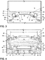
- the headboard 34 can be removed from the frame 12 by a caregiver, as illustrated in FIGS. 3 and 4 , to provide greater access to a head area of a patient disposed on the bed 10.
- the mattress 14 includes a head end 68 disposed on the head portion 16 of the frame 12.
- the head portion 16 of the frame 12 extends beyond the periphery 18 ( FIG. 5 ) of the mattress 14.
- the head portion 16 is configured to provide an interface between the frame 12 and each handle assembly 20.
- a protective shroud may be placed over portions of the frame 12. The protective shroud may, for example, be positioned between the mattress 14 and the frame 12.
- the head portion 16 generally defines a recess 70 configured to provide additional access to the patient by the caregiver.
- a rear wall 72 of the recess 70 is offset from an outer edge 74 of the frame 12.
- Opposing sidewalls 76, 78 of the recess 70 extend between the rear wall 72 and the outer edge 74.
- the opposing sidewalls 76, 78 generally extend at an oblique angle from the rear wall 72, such that the recess 70 defines a trapezoidal-shaped space.
- a wider space adjacent to the outer edge 74 of the frame 12 relative to the narrower space adjacent to the rear wall 72 of the recess 70 can be advantageous for providing comfort to a caregiver moving within the space.
- the opposing sidewalls 76, 78 extending at oblique angles can reduce sharp corners where a caregiver moves around to access the patient.
- the outer edge 74 is disposed a greater distance from the head end 68 of the mattress 14 relative to the rear wall 72 of the recess 70.
- the rear wall 72 of the recess 70 may be disposed about 6-inches from the periphery 18 of the head end 68 of the mattress 14.
- the outer edge 74 can be disposed about 9.5-inches from the outer periphery 18 ( FIG. 5 ) of the mattress 14.
- the recess 70 is centrally located in the head portion 16 of the frame 12.
- the recess 70 is generally defined between outwardly extending side projections 80, 82.
- the side projections 80, 82 each define an aperture 84, which is configured to hold and/or store removable medical supplies, such as, for example, an oxygen tank.
- the apertures 84 are generally centrally aligned with the rear wall 72 of the recess 70. When the caregiver is standing within the space defined by the recess 70, the caregiver can abut the rear wall 72. Having the apertures 84 with medical supplies aligned with the rear wall 72 can provide greater accessibility to the medical supplies by the caregiver.
- each handle assembly 20 is configured to rotate downward into abutment or close proximity to the head portion 16 of the frame 12.
- Each handle assembly 20 includes a base 90 that is secured to the head portion 16.
- the base 90 is pivotally coupled to the elongate member 22.
- the first handle assembly 20 is coupled to the head portion 16 proximate a first side of the recess 70 adjacent the first side projection 80
- the second handle assembly 20 is coupled to the head portion 16 proximate a second opposing side of the recess 70 adjacent the second side projection 82.
- a protective cover 94 in the form of a polymeric bellows is disposed on the elongate member 22 over a hinge assembly coupling the elongate member 22 with the base 90.
- each handle assembly 20 is operable to rotate or pivot inwardly between a deployed position ( FIGS. 3-5 ), where the elongate member 22 extends generally vertically, normal to a planar extent of a topside of the frame 12, and a stowed position ( FIG. 6 ) where the elongate member 22 and the handle 24 are abutting or in close proximity to the head portion 16.
- Each handle 24 includes a grip 100 that extends at an acute angle ⁇ from the distal end 26 of the elongate member 22.
- the grip 100 extends upwardly from the elongate member 22 at a 10 degree angle ⁇ relative to a longitudinal axis A defined by the elongate member 22. It will be understood that the grip 100 may extend upwardly from the elongate member 22 at any angle ⁇ between 4 degrees and 16 degrees relative to the longitudinal axis A of the elongate member 22.
- the elongate member 22 of the first handle assembly 20 When the elongate member 22 of the first handle assembly 20 is pivoted downward, the elongate member 22 pivots inwardly at least partially toward the mattress 14, and partially toward the second handle assembly 20.
- the first handle assembly 20 pivots directly over the head portion 16 of the frame 12.
- the second handle assembly 20 works in a similar fashion to the first handle assembly 20 and rotates inwardly at least partially toward the mattress 14, and partially toward the first handle assembly 20.
- the second handle assembly 20 pivots directly over the head portion 16 and does not impinge on the space provided by the recess 70 so that the caregiver has additional space to access an occupant of the bed 10 or to walk behind the bed 10, without the legs of the caregiver striking or hitting the frame.
- each handle 24 of each handle assembly 20 may include a variety of features, including the controls 58 to operate the motorized unit 54 ( FIG. 2 ).
- the motorized unit 54 can include a motor configured to move the bed 10 in a forward, rearward, or sideways direction.
- the grip 100 of each handle assembly 20 may include one or more indents 102 ( FIG. 6 ) to accommodate a hand of the user or caregiver.
- the indents 102 may define outer boundaries for the hand of the user and/or features to form a more ergonomic grasp for the user.
- each handle assembly 20 affords a substantial width of space W 1 that is equal to or greater than a width of the space W 2 defined by the recess 70 of the head portion 16.
- the grip 100 is illustrated extending at a 10 degree angle ⁇ relative to the longitudinal axis A of the elongate member 22. It will be understood that the grip 100 may extend at any angle ⁇ between 4 degrees and 16 degrees relative to the longitudinal axis A of the elongate member 22. It will also be noted that the grip 100 may be constructed of a polymeric high friction material, such as SantopreneTM, that is easily graspable by the caregiver.
- the elongate member 22 is generally defined by a tubular pole configured to house power and possibly data lines, which is advantageous when the handle assembly 20 includes the controls 58 ( FIG. 2 ). However, the elongate member 22 could take on other constructions and shapes.
- the handle assembly 20 is operable between the deployed position ( FIG. 5 ) and the stowed position ( FIG. 6 ).
- the handle assembly 20 When in the deployed position, the handle assembly 20 extends vertically from the head portion 16 of the frame 12. It may be beneficial for the user to push the handle assemblies 20 when the handle assemblies 20 are in the deployed position.
- the handle assemblies 20 can provide an ergonomic posture for pushing the bed 10.
- each handle assembly 20 rotates inwardly and slightly toward the mattress 14.
- Each handle assembly 20 pivots directly over the head portion 16 of the frame 12.
- the elongate member 22 and the grip 100 extend between the rear wall 72 of the recess 70 and the head end 68 of the mattress 14.
- the handle assembly 20 When in the stowed position, the handle assembly 20 can extend at an acute angle relative to the outer edge 74 of the frame 12. In a specific non-limiting example, the handle assembly 20 and the outer edge 74 of the frame 12 can define an angle of 19 degrees. However, it is contemplated that the handle assembly 20 can extend at any angle between about 15 degree and about 25 degrees relative to the outer edge 74 of the frame 12. The angled-orientation of the handle assembly 20 can prevent the handle assembly 20 from impeding on the space defined by the recess 70 when in the deployed position, the stowed position, and when pivoting therebetween. Accordingly, the caregiver has increased access to an occupant of the bed 10 when each handle assembly 20 is in the deployed position and in the stowed position.
- the frame 12 defines the recess 70 in the head portion 16 to provide greater access to a head area of the patient on the bed 10.
- the opposing sidewalls 76, 78 of the recess 70 extend at an oblique angle from the rear wall 72 of the recess 70 to provide increased comfort for the caregiver.
- the grip 100 can extend at an acute angle ⁇ from the distal end 26 of the elongate member 22 relative to the longitudinal extent of the elongate member 22. The angle ⁇ of the grip 100 can prevent the grip 100 from impinging the space defined by the recess 70.
- each handle assembly 20 can extend at an acute angle relative to the outer edge 74 of the frame 12 when in the stowed position.
- the angle of the elongate member 22 can prevent the handle assembly 20 from impinging the space defined by the recess 70.
- the handle assembly 20 can pivot directly over the head portion 16 of the frame 12 and extend between the rear wall 72 of the recess 70 and the head end 68 of the mattress 14.
- the term "coupled” in all of its forms, couple, coupling, coupled, etc. generally means the joining of two components (electrical or mechanical) directly or indirectly to one another. Such joining may be stationary in nature or movable in nature. Such joining may be achieved with the two components (electrical or mechanical) and any additional intermediate members being integrally formed as a single unitary body with one another or with the two components. Such joining may be permanent in nature or may be removable or releasable in nature unless otherwise stated.
- elements shown as integrally formed may be constructed of multiple parts, or elements shown as multiple parts may be integrally formed, the operation of the interfaces may be reversed or otherwise varied, the length or width of the structures and/or members or connector or other elements of the system may be varied, the nature or number of adjustment positions provided between the elements may be varied.
- the elements and/or assemblies of the system may be constructed from any of a wide variety of materials that provide sufficient strength or durability, in any of a wide variety of colors, textures, and combinations.
- Other substitutions, modifications, changes, and omissions may be made in the design, operating conditions, and arrangement of the desired and other exemplary embodiments.
Landscapes
- Health & Medical Sciences (AREA)
- Life Sciences & Earth Sciences (AREA)
- Animal Behavior & Ethology (AREA)
- General Health & Medical Sciences (AREA)
- Public Health (AREA)
- Veterinary Medicine (AREA)
- Nursing (AREA)
- Invalid Beds And Related Equipment (AREA)
Abstract
Description
- The present disclosure generally relates to providing increased access to a bed occupant by a caregiver at a head of the bed.
- According to one aspect of the present disclosure, a patient support apparatus includes a mattress having a head end. A frame is configured to support the mattress. The frame includes a head portion that extends beyond the head end of the mattress. The head portion defines a recess. At least one handle assembly is pivotally coupled to the head portion. The at least one handle assembly includes an elongate member coupled to the head portion proximate the recess. The elongate member is operable between a stowed position and a deployed position. The elongate member is disposed over the head portion when in the stowed position. A handle extends from a distal end of the elongate member. The handle extends at an acute angle relative to a longitudinal axis of the elongate member.
- According to another aspect of the present disclosure, a patient support apparatus includes a mattress having a head end. A frame is configured to support the mattress. The frame includes a head portion that extends beyond the head end of the mattress. The head portion of the frame defines a recess. Opposing sidewalls of the recess each extend at an oblique angle from a rear wall of the recess. A first handle assembly is pivotally coupled to a first side of the head portion. A second handle assembly is pivotally coupled to a second side of the head portion. Each of the first handle assembly and the second handle assembly are operable between a stowed position and a deployed position.
- According to another aspect of the present disclosure, a bed includes a frame configured to support a mattress. The frame includes a head portion configured to extend beyond an end of the mattress. A handle assembly extends from the head portion. The handle assembly includes an elongate member having a base pivotally coupled with the head portion. The elongate member is operable between a stowed position and a deployed position. A handle extends from a distal end of the elongate member. The handle extends from the distal end at an acute angle relative to a longitudinal axis of the elongate member.
- The invention will now be further described by way of example with reference to the accompanying drawings, in which:
-
FIG. 1 is a front perspective view of one aspect of a bed of the present disclosure; -
FIG. 2 is a box diagram of a bed of the present disclosure; -
FIG. 3 is a top plan view of a head portion of a bed of the present disclosure; -
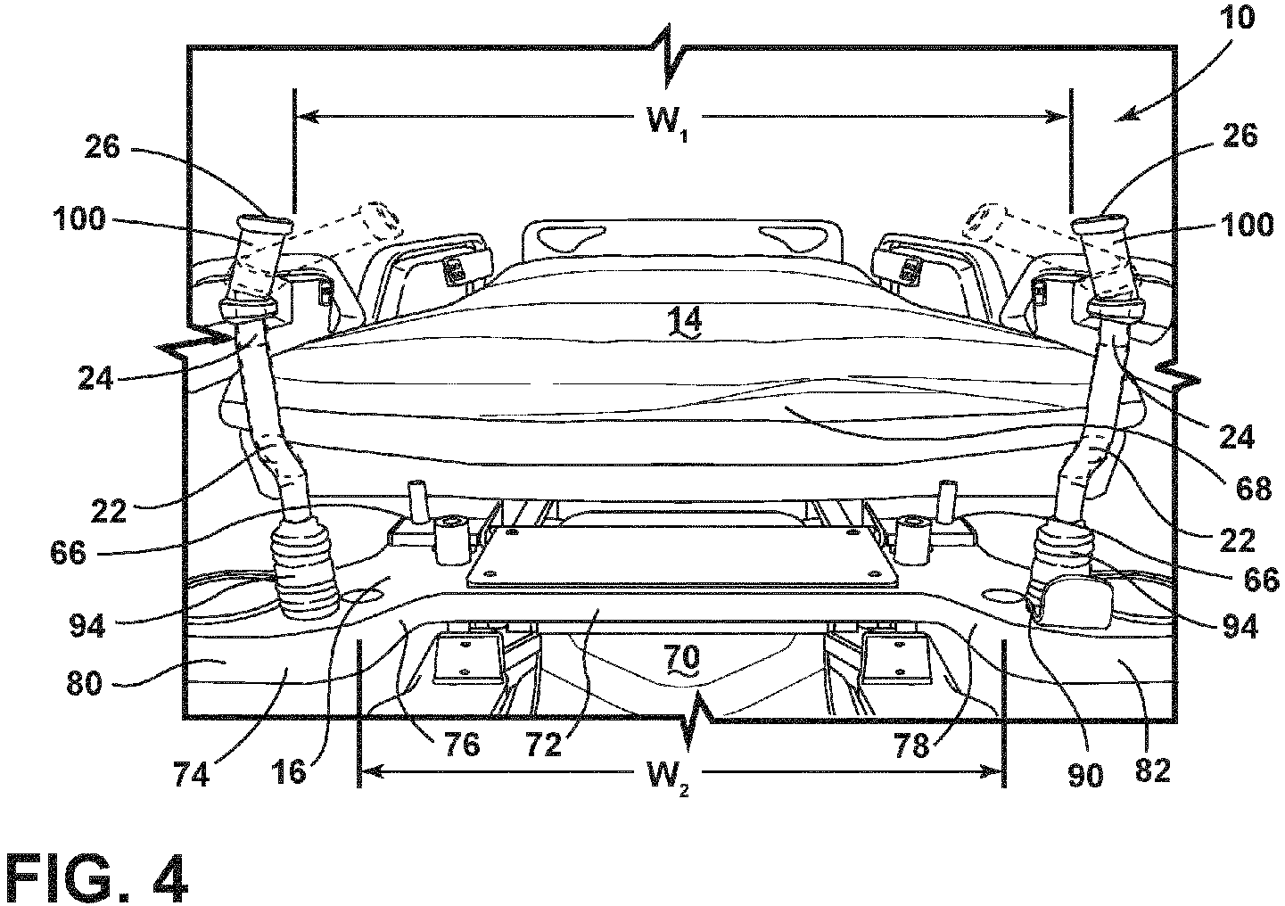
FIG. 4 is a side perspective view of a head portion a bed of the present disclosure; -
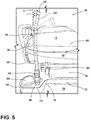
FIG. 5 is a partial side perspective view of a bed having a handle assembly of the present disclosure; and -
FIG. 6 is a top perspective view of a handle assembly for a bed, with the handle assembly in a stowed position. - The present illustrated embodiments reside primarily in combinations of method steps and apparatus components related to providing increased access to a bed occupant by a caregiver at a head of the bed. Accordingly, the apparatus components and method steps have been represented, where appropriate, by conventional symbols in the drawings, showing only those specific details that are pertinent to understanding the embodiments of the present disclosure so as not to obscure the disclosure with details that will be readily apparent to those of ordinary skill in the art having the benefit of the description herein. Further, like numerals in the description and drawings represent like elements.
- For purposes of description herein, the terms "upper," "lower," "right," "left," "rear," "front," "vertical," "horizontal," and derivatives thereof shall relate to the disclosure as oriented in
FIG. 1 . Unless stated otherwise, the term "front" shall refer to a surface of the device closest to an intended viewer, and the term "rear" shall refer to a surface of the device furthest from the intended viewer. However, it is to be understood that the disclosure may assume various alternative orientations, except where expressly specified to the contrary. It is also to be understood that the specific devices and processes illustrated in the attached drawings, and described in the following specification are simply exemplary embodiments. Hence, specific dimensions and other physical characteristics relating to the embodiments disclosed herein are not to be considered as limiting - The terms "including," "comprises," "comprising," or any other variation thereof, are intended to cover a non-exclusive inclusion, such that a process, method, article, or apparatus that comprises a list of elements does not include only those elements but may include other elements not expressly listed or inherent to such process, method, article, or apparatus. An element preceded by "comprises a ..." does not, without more constraints, preclude the existence of additional identical elements in the process, method, article, or apparatus that comprises the element.
- Referring to
FIGS. 1-6 ,reference numeral 10 generally designates a bed with abed frame 12 configured to support amattress 14. Theframe 12 includes ahead portion 16 configured to extend laterally beyond aperiphery 18 of themattress 14. At least onehandle assembly 20 extends from thehead portion 16. The at least onehandle assembly 20 includes anelongate member 22 pivotally coupled with thehead portion 16 and ahandle 24 that extends at an angle α from adistal end 26 of theelongate member 22. - With reference to
FIG. 1 , the illustrated bed may include a hospital bed. Thebed 10 also includes a surface, such as themattress 14, supported by theframe 12. While described as thebed 10, it is within the scope of the disclosure that thebed 10 may be any patient support apparatus known in the art and may include a patient support structure such as amattress 14, or any suitable structure for supporting a patient. - As illustrated, the
frame 12 of thebed 10 includes thehead portion 16 and afoot portion 28. Thebed 10 may include afootboard 32 at thefoot portion 28 and aheadboard 34 at thehead portion 16. Furthermore, thebed 10 may include a pair of headside rail assemblies 36 and a pair of footside rail assemblies 38. In some examples, agraphical user interface 40 is coupled to an external side of at least one side rail of theside rail assemblies graphical user interface 40 may be configured to accept a user input in order to control functions of themattress 14 and/or thebed 10. WhileFIG. 1 illustrates thegraphical user interface 40 coupled to the external side of at least one of the side rails of theside rail assemblies graphical user interface 40 may be coupled to any suitable component of thebed 10 for access by a user or caregiver. In some examples, thegraphical user interface 40 may be coupled to thefootboard 32 or theheadboard 34. - With reference to
FIGS. 1 and2 , theframe 12 is supported on casters orwheels 44 that engage with an underlying floor surface. Thewheels 44 are generally coupled to theframe 12 via an axle. Thewheels 44 can be configured to rotate in a power drive mode in order to propel thebed 10 for transportation by a caregiver, medical professional, or other users. - The
bed 10 includes acontroller 46 having aprocessor 48, amemory 50, and other control circuitry. Instructions orroutines 52 are stored in thememory 50 and executable by theprocessor 48. Thecontroller 46 may be in communication with various aspects of thebed 10 to communicate control signals. Thebed 10 may include a motorizedunit 54 operably coupled with adrive system 56 connected with theframe 12. In various aspects, theframe 12 may be operable between raised, lowered, and tilted positions. Thehandle assembly 20 can includecontrols 58 for operating themotorized unit 54. The caregiver or other medical professional can input a command through thecontrols 58, which can be communicated to thecontroller 46. Thecontroller 46 can send a corresponding signal to control thebed 10 in response to the command. - The
bed 10 may include various mattress function technologies, such as a microclimate management (MCM)system 60. TheMCM system 60 may address shear, friction, pressure, and moisture properties of themattress 14 in order to optimize patient comfort and to keep a patient's skin cool and dry, which may aid in the prevention of complications in patient recovery, such as wound prevention. TheMCM system 60 may automatically make adjustments based on predetermined therapy functions or manually make adjustments based on user input commands received from thegraphical user interface 40. Thebed 10 may further include apneumatic system 62 that provides air for operation of theMCM system 60. Furthermore, thepneumatic system 62 may control airflow in and out of various air bladders or cells of themattress 14. In some examples, an MCM system status floor indicator may be projected as an image onto the floor surface from aprojector 64 coupled with thefoot portion 28 of thebed 10 to indicate whether theMCM system 60 is on or off and in what state theMCM system 60 is operating. - With reference to
FIGS. 1 ,3, and 4 , theheadboard 34 can be selectively engaged with theframe 12. Theheadboard 34 may be coupled to thehead portion 16 of theframe 12, as illustrated inFIG. 1 , via retainingbrackets 66. The retainingbrackets 66 operate to hold theheadboard 34 in position on thehead portion 16. Theheadboard 34 can be removed from theframe 12 by a caregiver, as illustrated inFIGS. 3 and 4 , to provide greater access to a head area of a patient disposed on thebed 10. - With reference to
FIGS. 3 and 4 , themattress 14 includes ahead end 68 disposed on thehead portion 16 of theframe 12. Thehead portion 16 of theframe 12 extends beyond the periphery 18 (FIG. 5 ) of themattress 14. Thehead portion 16 is configured to provide an interface between theframe 12 and eachhandle assembly 20. In some examples, a protective shroud may be placed over portions of theframe 12. The protective shroud may, for example, be positioned between themattress 14 and theframe 12. - The
head portion 16 generally defines arecess 70 configured to provide additional access to the patient by the caregiver. Arear wall 72 of therecess 70 is offset from anouter edge 74 of theframe 12. Opposingsidewalls recess 70 extend between therear wall 72 and theouter edge 74. The opposingsidewalls rear wall 72, such that therecess 70 defines a trapezoidal-shaped space. A wider space adjacent to theouter edge 74 of theframe 12 relative to the narrower space adjacent to therear wall 72 of therecess 70 can be advantageous for providing comfort to a caregiver moving within the space. The opposingsidewalls - The
outer edge 74 is disposed a greater distance from thehead end 68 of themattress 14 relative to therear wall 72 of therecess 70. In a non-limiting example, therear wall 72 of therecess 70 may be disposed about 6-inches from theperiphery 18 of thehead end 68 of themattress 14. In such examples, theouter edge 74 can be disposed about 9.5-inches from the outer periphery 18 (FIG. 5 ) of themattress 14. - As illustrated, the
recess 70 is centrally located in thehead portion 16 of theframe 12. Therecess 70 is generally defined between outwardly extendingside projections side projections aperture 84, which is configured to hold and/or store removable medical supplies, such as, for example, an oxygen tank. Theapertures 84 are generally centrally aligned with therear wall 72 of therecess 70. When the caregiver is standing within the space defined by therecess 70, the caregiver can abut therear wall 72. Having theapertures 84 with medical supplies aligned with therear wall 72 can provide greater accessibility to the medical supplies by the caregiver. - Referring still to
FIGS. 3 and 4 , eachhandle assembly 20 is configured to rotate downward into abutment or close proximity to thehead portion 16 of theframe 12. Eachhandle assembly 20 includes a base 90 that is secured to thehead portion 16. Thebase 90 is pivotally coupled to theelongate member 22. Generally, thefirst handle assembly 20 is coupled to thehead portion 16 proximate a first side of therecess 70 adjacent thefirst side projection 80, and thesecond handle assembly 20 is coupled to thehead portion 16 proximate a second opposing side of therecess 70 adjacent thesecond side projection 82. Aprotective cover 94 in the form of a polymeric bellows is disposed on theelongate member 22 over a hinge assembly coupling theelongate member 22 with thebase 90. - In addition, each
handle assembly 20 is operable to rotate or pivot inwardly between a deployed position (FIGS. 3-5 ), where theelongate member 22 extends generally vertically, normal to a planar extent of a topside of theframe 12, and a stowed position (FIG. 6 ) where theelongate member 22 and thehandle 24 are abutting or in close proximity to thehead portion 16. Each handle 24 includes agrip 100 that extends at an acute angle α from thedistal end 26 of theelongate member 22. In one example, thegrip 100 extends upwardly from theelongate member 22 at a 10 degree angle α relative to a longitudinal axis A defined by theelongate member 22. It will be understood that thegrip 100 may extend upwardly from theelongate member 22 at any angle α between 4 degrees and 16 degrees relative to the longitudinal axis A of theelongate member 22. - When the
elongate member 22 of thefirst handle assembly 20 is pivoted downward, theelongate member 22 pivots inwardly at least partially toward themattress 14, and partially toward thesecond handle assembly 20. Thefirst handle assembly 20 pivots directly over thehead portion 16 of theframe 12. As a result, the additional space provided by therecess 70 is not impinged. Thesecond handle assembly 20 works in a similar fashion to thefirst handle assembly 20 and rotates inwardly at least partially toward themattress 14, and partially toward thefirst handle assembly 20. Once again, thesecond handle assembly 20 pivots directly over thehead portion 16 and does not impinge on the space provided by therecess 70 so that the caregiver has additional space to access an occupant of thebed 10 or to walk behind thebed 10, without the legs of the caregiver striking or hitting the frame. - It will be understood that the
grip 100 on each handle 24 of eachhandle assembly 20 may include a variety of features, including thecontrols 58 to operate the motorized unit 54 (FIG. 2 ). Themotorized unit 54 can include a motor configured to move thebed 10 in a forward, rearward, or sideways direction. Thegrip 100 of eachhandle assembly 20 may include one or more indents 102 (FIG. 6 ) to accommodate a hand of the user or caregiver. Theindents 102 may define outer boundaries for the hand of the user and/or features to form a more ergonomic grasp for the user. In addition, it will be understood that when in the upright, deployed position, eachhandle assembly 20 affords a substantial width of space W1 that is equal to or greater than a width of the space W2 defined by therecess 70 of thehead portion 16. - With regard to
FIG. 5 , thegrip 100 is illustrated extending at a 10 degree angle α relative to the longitudinal axis A of theelongate member 22. It will be understood that thegrip 100 may extend at any angle α between 4 degrees and 16 degrees relative to the longitudinal axis A of theelongate member 22. It will also be noted that thegrip 100 may be constructed of a polymeric high friction material, such as Santoprene™, that is easily graspable by the caregiver. Theelongate member 22 is generally defined by a tubular pole configured to house power and possibly data lines, which is advantageous when thehandle assembly 20 includes the controls 58 (FIG. 2 ). However, theelongate member 22 could take on other constructions and shapes. - Referring to
FIGS. 5 and6 , thehandle assembly 20 is operable between the deployed position (FIG. 5 ) and the stowed position (FIG. 6 ). When in the deployed position, thehandle assembly 20 extends vertically from thehead portion 16 of theframe 12. It may be beneficial for the user to push thehandle assemblies 20 when thehandle assemblies 20 are in the deployed position. Thehandle assemblies 20 can provide an ergonomic posture for pushing thebed 10. - When the
elongate member 22 is rotated downward against, or in close proximity to, thehead portion 16 of theframe 12, theelongate member 22 and thegrip 100 do not extend into the space defined by therecess 70. Rather, eachhandle assembly 20 rotates inwardly and slightly toward themattress 14. Eachhandle assembly 20 pivots directly over thehead portion 16 of theframe 12. When in the stowed position, theelongate member 22 and thegrip 100 extend between therear wall 72 of therecess 70 and thehead end 68 of themattress 14. - When in the stowed position, the
handle assembly 20 can extend at an acute angle relative to theouter edge 74 of theframe 12. In a specific non-limiting example, thehandle assembly 20 and theouter edge 74 of theframe 12 can define an angle of 19 degrees. However, it is contemplated that thehandle assembly 20 can extend at any angle between about 15 degree and about 25 degrees relative to theouter edge 74 of theframe 12. The angled-orientation of thehandle assembly 20 can prevent thehandle assembly 20 from impeding on the space defined by therecess 70 when in the deployed position, the stowed position, and when pivoting therebetween. Accordingly, the caregiver has increased access to an occupant of thebed 10 when eachhandle assembly 20 is in the deployed position and in the stowed position. - Use of the present device may provide for a variety of advantages. For example, the
frame 12 defines therecess 70 in thehead portion 16 to provide greater access to a head area of the patient on thebed 10. Further, the opposingsidewalls recess 70 extend at an oblique angle from therear wall 72 of therecess 70 to provide increased comfort for the caregiver. Additionally, thegrip 100 can extend at an acute angle α from thedistal end 26 of theelongate member 22 relative to the longitudinal extent of theelongate member 22. The angle α of thegrip 100 can prevent thegrip 100 from impinging the space defined by therecess 70. Moreover, eachhandle assembly 20 can extend at an acute angle relative to theouter edge 74 of theframe 12 when in the stowed position. The angle of theelongate member 22 can prevent thehandle assembly 20 from impinging the space defined by therecess 70. Accordingly, thehandle assembly 20 can pivot directly over thehead portion 16 of theframe 12 and extend between therear wall 72 of therecess 70 and thehead end 68 of themattress 14. These and other benefits or advantages can also be realized and/or achieved. - For purposes of this disclosure, the term "coupled" (in all of its forms, couple, coupling, coupled, etc.) generally means the joining of two components (electrical or mechanical) directly or indirectly to one another. Such joining may be stationary in nature or movable in nature. Such joining may be achieved with the two components (electrical or mechanical) and any additional intermediate members being integrally formed as a single unitary body with one another or with the two components. Such joining may be permanent in nature or may be removable or releasable in nature unless otherwise stated.
- It is also important to note that the construction and arrangement of the elements of the disclosure, as shown in the exemplary embodiments, is illustrative only. Although only a few embodiments of the present innovations have been described in detail in this disclosure, those skilled in the art who review this disclosure will readily appreciate that many modifications are possible (e.g., variations in sizes, dimensions, structures, shapes and proportions of the various elements, values of parameters, mounting arrangements, use of materials, colors, orientations, etc.) without materially departing from the novel teachings and advantages of the subject matter recited. For example, elements shown as integrally formed may be constructed of multiple parts, or elements shown as multiple parts may be integrally formed, the operation of the interfaces may be reversed or otherwise varied, the length or width of the structures and/or members or connector or other elements of the system may be varied, the nature or number of adjustment positions provided between the elements may be varied. It should be noted that the elements and/or assemblies of the system may be constructed from any of a wide variety of materials that provide sufficient strength or durability, in any of a wide variety of colors, textures, and combinations. Other substitutions, modifications, changes, and omissions may be made in the design, operating conditions, and arrangement of the desired and other exemplary embodiments.
- It will be understood that any described processes or steps within described processes may be combined with other disclosed processes or steps. The exemplary structures and processes disclosed herein are for illustrative purposes and are not to be construed as limiting.
- Embodiments of the invention can be described with reference to the following numbered clauses, with preferred features laid out in the dependent clauses:
- 1. A patient support apparatus, comprising: a mattress having a head end; a frame configured to support the mattress, wherein the frame includes a head portion that extends beyond the head end of the mattress, and wherein the head portion defines a recess; and at least one handle assembly pivotally coupled to the head portion, wherein the at least one handle assembly includes: an elongate member coupled to the head portion proximate the recess, wherein the elongate member is operable between a stowed position and a deployed position, and wherein the elongate member is disposed over the head portion when in the stowed position; and a handle extending from a distal end of the elongate member, wherein the handle extends at an acute angle relative to a longitudinal axis of the elongate member.
- 2. The patient support apparatus of clause 1, wherein the at least one handle assembly extends between the recess and the head end when in the stowed position.
- 3. The patient support apparatus of either of clause 1 or
clause 2, wherein the at least one handle assembly includes a first handle assembly coupled to the head portion on a first side of the recess and a second handle assembly coupled to the head portion on a second side of the recess. - 4. The patient support apparatus of clause 3, wherein the elongate member of each of the first handle assembly and the second handle assembly pivots directly over the head portion.
- 5. The patient support apparatus of any of clauses 1-4, wherein the elongate member extends over the head portion at an acute angle between 15 degrees and 25 degrees relative to an outer edge of the frame.
- 6. A bed, comprising: a frame configured to support a mattress, wherein the frame includes a head portion configured to extend beyond an end of the mattress; and a handle assembly extending from the head portion, wherein the handle assembly includes: an elongate member having a base pivotally coupled with the head portion, wherein the elongate member is operable between a stowed position and a deployed position; and a handle extending from a distal end of the elongate member, wherein the handle extends from the distal end at an acute angle relative to a longitudinal axis of the elongate member.
- 7. The bed of clause 6, wherein the head portion defines a centrally located recess.
- 8. The bed of clause 7, wherein the recess is defined by a rear wall and opposing sidewalls, and wherein the opposing sidewalls each extend at an oblique angle from the rear wall.
- 9. The bed of either clause 7 or clause 8, wherein the elongate member and the handle extend over the head portion of the frame between the recess and the end of the mattress when in the stowed position.
- 10. The bed of any of clauses 6-9, wherein the elongate member pivots directly over the head portion.
- 11. The bed of any of clauses 6-10, wherein the handle assembly extends at an angle between 15 degrees and 25 degrees relative to an outer edge of the frame when in the stowed position.
Claims (15)
- A patient support apparatus (10), comprising:a mattress (14) having a head end (68);a frame (12) configured to support the mattress (14), wherein the frame (12) includes a head portion (16) that extends beyond the head end (68) of the mattress (14), wherein the head portion (16) of the frame (12) defines a recess (70), and wherein opposing sidewalls (76, 78) of the recess (70) each extend at an oblique angle from a rear wall (72) of the recess (70);a first handle assembly (20) pivotally coupled to a first side of the head portion (16); anda second handle assembly (20) pivotally coupled to a second side of the head portion (16), wherein each of the first handle assembly (20) and the second handle assembly (20) are operable between a stowed position and a deployed position.
- The patient support apparatus (10) of claim 1, wherein each of the first handle assembly (20) and the second handle assembly (20) includes an elongate member (22) and a handle (24).
- The patient support apparatus (10) of claim 2, wherein the handle (24) extends from at an acute angle relative to a longitudinal axis of the elongate member (22), respectively.
- The patient support apparatus (10) of claim 3, wherein the acute angle is between 4 degrees and 16 degrees relative to the longitudinal axis of the elongate member (22), respectively.
- The patient support apparatus (10) of any one of claims 2-4, wherein the handle (24) of each of the first handle assembly (20) and the second handle assembly (20) includes controls to operate a motorized unit (54) operably coupled with a drive system (56) connected with the frame (12).
- The patient support apparatus (10) of any one of claims 2-5, wherein each elongate member (22) has a base (90) pivotally coupled to the head portion (16), and wherein the handle (24) extends from a distal end (26) of the elongate member (22), respectively.
- The patient support apparatus (10) of any one of claims 2-6, wherein each elongate member (22) is coupled to the head portion (16) proximate the recess (70).
- The patient support apparatus (10) of any one of claims 1-7, wherein each of the first handle assembly (20) and the second handle assembly (20) pivot directly over the head portion (16).
- The patient support apparatus (10) of any one of claims 1-8, wherein the recess (70) is centrally located between side projections (80, 82).
- The patient support apparatus (10) of claim 9, wherein the side projections (80, 82) each define an aperture (84) configured to store removable medical supplies.
- The patient support apparatus (10) of any one of claims 1-10, wherein each of the first handle assembly (20) and the second handle assembly (20) extend between the rear wall (72) of the recess (70) and the head end (68) of the mattress (14) when in the stowed position.
- The patient support apparatus (10) of any one of claims 1-11, wherein the first handle assembly (20) is coupled to the head portion (16) on a first side of the recess (70) and the second handle assembly (20) coupled to the head portion (16) on a second side of the recess (70).
- The patient support apparatus (10) of any one of claims 1-12, wherein each of the first handle assembly (20) and the second handle assembly (20) extends over the head portion (16) when in the stowed position.
- The patient support apparatus (10) of any one of claims 1-13, wherein each of the first handle assembly (20) and the second handle assembly (20) extends at an acute angle relative to an outer edge (74) of the frame (12) when in the stowed position.
- The patient support apparatus (10) of claim 14, wherein the acute angle is between 15 degrees and 25 degrees relative to the outer edge (74) of the frame (12).
Priority Applications (1)
| Application Number | Priority Date | Filing Date | Title |
|---|---|---|---|
| EP25185961.7A EP4599812A3 (en) | 2019-04-17 | 2020-04-16 | Head of bed access |
Applications Claiming Priority (2)
| Application Number | Priority Date | Filing Date | Title |
|---|---|---|---|
| US201962835266P | 2019-04-17 | 2019-04-17 | |
| US16/849,090 US11304866B2 (en) | 2019-04-17 | 2020-04-15 | Head of bed access |
Related Child Applications (2)
| Application Number | Title | Priority Date | Filing Date |
|---|---|---|---|
| EP25185961.7A Division EP4599812A3 (en) | 2019-04-17 | 2020-04-16 | Head of bed access |
| EP25185961.7A Division-Into EP4599812A3 (en) | 2019-04-17 | 2020-04-16 | Head of bed access |
Publications (2)
| Publication Number | Publication Date |
|---|---|
| EP3725280A1 true EP3725280A1 (en) | 2020-10-21 |
| EP3725280B1 EP3725280B1 (en) | 2025-08-06 |
Family
ID=70294949
Family Applications (2)
| Application Number | Title | Priority Date | Filing Date |
|---|---|---|---|
| EP25185961.7A Pending EP4599812A3 (en) | 2019-04-17 | 2020-04-16 | Head of bed access |
| EP20169946.9A Active EP3725280B1 (en) | 2019-04-17 | 2020-04-16 | Head of bed access |
Family Applications Before (1)
| Application Number | Title | Priority Date | Filing Date |
|---|---|---|---|
| EP25185961.7A Pending EP4599812A3 (en) | 2019-04-17 | 2020-04-16 | Head of bed access |
Country Status (2)
| Country | Link |
|---|---|
| US (1) | US11304866B2 (en) |
| EP (2) | EP4599812A3 (en) |
Families Citing this family (2)
| Publication number | Priority date | Publication date | Assignee | Title |
|---|---|---|---|---|
| US11648162B2 (en) | 2019-07-31 | 2023-05-16 | Hill-Rom Services, Inc. | Head extension and transport handle system |
| US12589042B2 (en) * | 2022-04-18 | 2026-03-31 | Hill-Rom Services, Inc. | Surface adaptation for patient proning |
Citations (3)
| Publication number | Priority date | Publication date | Assignee | Title |
|---|---|---|---|---|
| US5069465A (en) * | 1990-01-26 | 1991-12-03 | Stryker Corporation | Dual position push handles for hospital stretcher |
| US20080141459A1 (en) * | 2006-10-13 | 2008-06-19 | Hamberg Stephen R | Push handle with rotatable user interface |
| US20100138999A1 (en) * | 2008-12-10 | 2010-06-10 | Westmoreland Ii Ted Carson | Collapsible litter apparatus, system and method |
Family Cites Families (18)
| Publication number | Priority date | Publication date | Assignee | Title |
|---|---|---|---|---|
| JP3740459B2 (en) | 2002-11-26 | 2006-02-01 | 京セラ株式会社 | Fuel cell container and fuel cell |
| US7124456B2 (en) * | 2004-08-11 | 2006-10-24 | Stryker Corporation | Articulated support surface for a stretcher or gurney |
| US7419019B1 (en) * | 2006-03-23 | 2008-09-02 | Safe-T-Care Manufacturing, Co., Inc. | Power assist apparatus for use with a hospital bed |
| CN101420888B (en) * | 2006-04-17 | 2012-02-15 | 凯希特许有限公司 | System and method for bed transport |
| US7882582B2 (en) | 2006-10-13 | 2011-02-08 | Hill-Rom Services, Inc. | User interface and control system for powered transport device of a patient support apparatus |
| US7789187B2 (en) * | 2008-01-29 | 2010-09-07 | Hill-Rom Services, Inc. | Push handle with pivotable handle post |
| US9107783B2 (en) * | 2009-10-12 | 2015-08-18 | Stryker Corporation | Patient handling device |
| WO2012006545A2 (en) | 2010-07-09 | 2012-01-12 | Hill-Rom Services, Inc. | Person support systems, devices, and methods |
| WO2014025702A1 (en) | 2012-08-06 | 2014-02-13 | Xcelerator Labs, Llc | Sterile surgical drape for ophthalmic surgery |
| US9233038B2 (en) | 2012-09-04 | 2016-01-12 | Hill-Rom Services, Inc. | Patient support with a microclimate system and a graphical user interface |
| US9205009B2 (en) | 2012-12-17 | 2015-12-08 | Hill-Rom Services, Inc. | Patient support apparatus having movable handles |
| GB2538442B (en) | 2014-02-14 | 2020-10-07 | Stryker Corp | Communication methods for patient handling devices |
| US9463126B2 (en) | 2014-03-11 | 2016-10-11 | Hill-Rom Services, Inc. | Caregiver universal remote cart for patient bed control |
| US10363182B2 (en) * | 2014-07-14 | 2019-07-30 | Hill-Rom Services, Inc. | Patient control arm with phone dock and head of bed lockout |
| JP6647284B2 (en) | 2014-08-19 | 2020-02-14 | ファーノ−ワシントン・インコーポレーテッド | Cot fastening system with crash stable cot fastener truck and method of securing an emergency cot thereto |
| CN108028005A (en) | 2015-05-29 | 2018-05-11 | 希尔-罗姆服务公司 | Patient support apparatus |
| US10406044B2 (en) * | 2015-06-25 | 2019-09-10 | Stryker Corporation | Person support apparatuses with drive controls |
| GB2562615B (en) * | 2017-03-30 | 2020-07-22 | Stryker Corp | Patient transport apparatus with adjustable handles |
-
2020
- 2020-04-15 US US16/849,090 patent/US11304866B2/en active Active
- 2020-04-16 EP EP25185961.7A patent/EP4599812A3/en active Pending
- 2020-04-16 EP EP20169946.9A patent/EP3725280B1/en active Active
Patent Citations (3)
| Publication number | Priority date | Publication date | Assignee | Title |
|---|---|---|---|---|
| US5069465A (en) * | 1990-01-26 | 1991-12-03 | Stryker Corporation | Dual position push handles for hospital stretcher |
| US20080141459A1 (en) * | 2006-10-13 | 2008-06-19 | Hamberg Stephen R | Push handle with rotatable user interface |
| US20100138999A1 (en) * | 2008-12-10 | 2010-06-10 | Westmoreland Ii Ted Carson | Collapsible litter apparatus, system and method |
Also Published As
| Publication number | Publication date |
|---|---|
| US11304866B2 (en) | 2022-04-19 |
| EP4599812A3 (en) | 2025-11-05 |
| US20200330302A1 (en) | 2020-10-22 |
| EP4599812A2 (en) | 2025-08-13 |
| EP3725280B1 (en) | 2025-08-06 |
Similar Documents
| Publication | Publication Date | Title |
|---|---|---|
| US10583852B2 (en) | Foldable wagon | |
| US8296884B2 (en) | Siderail gap filler | |
| US8336142B1 (en) | Body and head support | |
| US7257850B1 (en) | Articulating bed frame | |
| US9358169B2 (en) | Drive system for bed | |
| CN105534136B (en) | Automatic lifting pillow | |
| US7093312B2 (en) | Single motor adjustable bed | |
| US9333132B2 (en) | Wheelchair lift system and method | |
| CN105392458B (en) | Wheelchair with tilt function | |
| EP3725280B1 (en) | Head of bed access | |
| JP5000710B2 (en) | Operating table guidance device | |
| CA2982585A1 (en) | Docking systems for medical devices and related devices | |
| JP6754758B2 (en) | Beds and bed inserts with postural support | |
| US20170224558A1 (en) | Foldable electric wheelchair | |
| US20210401643A1 (en) | Wheelchair systems and methods having a brace assembly | |
| KR101455476B1 (en) | Suction opening body and electric cleaner | |
| US10898000B2 (en) | Leg extension for procedure chair | |
| JP2005124796A (en) | Headrest device, medical chair equipped with the headrest device, and medical bed | |
| KR101455477B1 (en) | Electric cleaner | |
| EP3771457B1 (en) | Head extension and transport handle system | |
| EP4210544B1 (en) | A kit comprising a camping mattress and a roof tent | |
| JPH11178756A (en) | Electric vacuum cleaner | |
| KR20130075685A (en) | Suction opening body and electric cleaner | |
| JP2005124795A (en) | Armchair | |
| JP3064147U (en) | Electric simple folding bed |
Legal Events
| Date | Code | Title | Description |
|---|---|---|---|
| PUAI | Public reference made under article 153(3) epc to a published international application that has entered the european phase |
Free format text: ORIGINAL CODE: 0009012 |
|
| STAA | Information on the status of an ep patent application or granted ep patent |
Free format text: STATUS: THE APPLICATION HAS BEEN PUBLISHED |
|
| AK | Designated contracting states |
Kind code of ref document: A1 Designated state(s): AL AT BE BG CH CY CZ DE DK EE ES FI FR GB GR HR HU IE IS IT LI LT LU LV MC MK MT NL NO PL PT RO RS SE SI SK SM TR |
|
| AX | Request for extension of the european patent |
Extension state: BA ME |
|
| STAA | Information on the status of an ep patent application or granted ep patent |
Free format text: STATUS: REQUEST FOR EXAMINATION WAS MADE |
|
| 17P | Request for examination filed |
Effective date: 20210420 |
|
| RBV | Designated contracting states (corrected) |
Designated state(s): AL AT BE BG CH CY CZ DE DK EE ES FI FR GB GR HR HU IE IS IT LI LT LU LV MC MK MT NL NO PL PT RO RS SE SI SK SM TR |
|
| STAA | Information on the status of an ep patent application or granted ep patent |
Free format text: STATUS: EXAMINATION IS IN PROGRESS |
|
| 17Q | First examination report despatched |
Effective date: 20230203 |
|
| GRAP | Despatch of communication of intention to grant a patent |
Free format text: ORIGINAL CODE: EPIDOSNIGR1 |
|
| STAA | Information on the status of an ep patent application or granted ep patent |
Free format text: STATUS: GRANT OF PATENT IS INTENDED |
|
| INTG | Intention to grant announced |
Effective date: 20250227 |
|
| GRAS | Grant fee paid |
Free format text: ORIGINAL CODE: EPIDOSNIGR3 |
|
| GRAA | (expected) grant |
Free format text: ORIGINAL CODE: 0009210 |
|
| STAA | Information on the status of an ep patent application or granted ep patent |
Free format text: STATUS: THE PATENT HAS BEEN GRANTED |
|
| P01 | Opt-out of the competence of the unified patent court (upc) registered |
Free format text: CASE NUMBER: APP_28923/2025 Effective date: 20250617 |
|
| AK | Designated contracting states |
Kind code of ref document: B1 Designated state(s): AL AT BE BG CH CY CZ DE DK EE ES FI FR GB GR HR HU IE IS IT LI LT LU LV MC MK MT NL NO PL PT RO RS SE SI SK SM TR |
|
| REG | Reference to a national code |
Ref country code: GB Ref legal event code: FG4D |
|
| REG | Reference to a national code |
Ref country code: CH Ref legal event code: EP |
|
| REG | Reference to a national code |
Ref country code: DE Ref legal event code: R096 Ref document number: 602020055809 Country of ref document: DE |
|
| REG | Reference to a national code |
Ref country code: IE Ref legal event code: FG4D |
|
| REG | Reference to a national code |
Ref country code: NL Ref legal event code: MP Effective date: 20250806 |
|
| PG25 | Lapsed in a contracting state [announced via postgrant information from national office to epo] |
Ref country code: IS Free format text: LAPSE BECAUSE OF FAILURE TO SUBMIT A TRANSLATION OF THE DESCRIPTION OR TO PAY THE FEE WITHIN THE PRESCRIBED TIME-LIMIT Effective date: 20251206 |
|
| PG25 | Lapsed in a contracting state [announced via postgrant information from national office to epo] |
Ref country code: NO Free format text: LAPSE BECAUSE OF FAILURE TO SUBMIT A TRANSLATION OF THE DESCRIPTION OR TO PAY THE FEE WITHIN THE PRESCRIBED TIME-LIMIT Effective date: 20251106 |
|
| REG | Reference to a national code |
Ref country code: LT Ref legal event code: MG9D |
|
| PG25 | Lapsed in a contracting state [announced via postgrant information from national office to epo] |
Ref country code: PT Free format text: LAPSE BECAUSE OF FAILURE TO SUBMIT A TRANSLATION OF THE DESCRIPTION OR TO PAY THE FEE WITHIN THE PRESCRIBED TIME-LIMIT Effective date: 20251209 |
|
| PG25 | Lapsed in a contracting state [announced via postgrant information from national office to epo] |
Ref country code: FI Free format text: LAPSE BECAUSE OF FAILURE TO SUBMIT A TRANSLATION OF THE DESCRIPTION OR TO PAY THE FEE WITHIN THE PRESCRIBED TIME-LIMIT Effective date: 20250806 |
|
| PG25 | Lapsed in a contracting state [announced via postgrant information from national office to epo] |
Ref country code: HR Free format text: LAPSE BECAUSE OF FAILURE TO SUBMIT A TRANSLATION OF THE DESCRIPTION OR TO PAY THE FEE WITHIN THE PRESCRIBED TIME-LIMIT Effective date: 20250806 Ref country code: NL Free format text: LAPSE BECAUSE OF FAILURE TO SUBMIT A TRANSLATION OF THE DESCRIPTION OR TO PAY THE FEE WITHIN THE PRESCRIBED TIME-LIMIT Effective date: 20250806 |
|
| PG25 | Lapsed in a contracting state [announced via postgrant information from national office to epo] |
Ref country code: GR Free format text: LAPSE BECAUSE OF FAILURE TO SUBMIT A TRANSLATION OF THE DESCRIPTION OR TO PAY THE FEE WITHIN THE PRESCRIBED TIME-LIMIT Effective date: 20251107 |
|
| PG25 | Lapsed in a contracting state [announced via postgrant information from national office to epo] |
Ref country code: SE Free format text: LAPSE BECAUSE OF FAILURE TO SUBMIT A TRANSLATION OF THE DESCRIPTION OR TO PAY THE FEE WITHIN THE PRESCRIBED TIME-LIMIT Effective date: 20250806 |
|
| PG25 | Lapsed in a contracting state [announced via postgrant information from national office to epo] |
Ref country code: LV Free format text: LAPSE BECAUSE OF FAILURE TO SUBMIT A TRANSLATION OF THE DESCRIPTION OR TO PAY THE FEE WITHIN THE PRESCRIBED TIME-LIMIT Effective date: 20250806 |
|
| PG25 | Lapsed in a contracting state [announced via postgrant information from national office to epo] |
Ref country code: PL Free format text: LAPSE BECAUSE OF FAILURE TO SUBMIT A TRANSLATION OF THE DESCRIPTION OR TO PAY THE FEE WITHIN THE PRESCRIBED TIME-LIMIT Effective date: 20250806 Ref country code: BG Free format text: LAPSE BECAUSE OF FAILURE TO SUBMIT A TRANSLATION OF THE DESCRIPTION OR TO PAY THE FEE WITHIN THE PRESCRIBED TIME-LIMIT Effective date: 20250806 |
|
| PG25 | Lapsed in a contracting state [announced via postgrant information from national office to epo] |
Ref country code: RS Free format text: LAPSE BECAUSE OF FAILURE TO SUBMIT A TRANSLATION OF THE DESCRIPTION OR TO PAY THE FEE WITHIN THE PRESCRIBED TIME-LIMIT Effective date: 20251106 |
|
| PG25 | Lapsed in a contracting state [announced via postgrant information from national office to epo] |
Ref country code: ES Free format text: LAPSE BECAUSE OF FAILURE TO SUBMIT A TRANSLATION OF THE DESCRIPTION OR TO PAY THE FEE WITHIN THE PRESCRIBED TIME-LIMIT Effective date: 20250806 |
|
| REG | Reference to a national code |
Ref country code: AT Ref legal event code: MK05 Ref document number: 1820931 Country of ref document: AT Kind code of ref document: T Effective date: 20250806 |
|
| PG25 | Lapsed in a contracting state [announced via postgrant information from national office to epo] |
Ref country code: SM Free format text: LAPSE BECAUSE OF FAILURE TO SUBMIT A TRANSLATION OF THE DESCRIPTION OR TO PAY THE FEE WITHIN THE PRESCRIBED TIME-LIMIT Effective date: 20250806 |
|
| PGFP | Annual fee paid to national office [announced via postgrant information from national office to epo] |
Ref country code: GB Payment date: 20260319 Year of fee payment: 7 |
|
| PG25 | Lapsed in a contracting state [announced via postgrant information from national office to epo] |
Ref country code: DK Free format text: LAPSE BECAUSE OF FAILURE TO SUBMIT A TRANSLATION OF THE DESCRIPTION OR TO PAY THE FEE WITHIN THE PRESCRIBED TIME-LIMIT Effective date: 20250806 |
|
| PG25 | Lapsed in a contracting state [announced via postgrant information from national office to epo] |
Ref country code: AT Free format text: LAPSE BECAUSE OF FAILURE TO SUBMIT A TRANSLATION OF THE DESCRIPTION OR TO PAY THE FEE WITHIN THE PRESCRIBED TIME-LIMIT Effective date: 20250806 |
|
| PG25 | Lapsed in a contracting state [announced via postgrant information from national office to epo] |
Ref country code: IT Free format text: LAPSE BECAUSE OF FAILURE TO SUBMIT A TRANSLATION OF THE DESCRIPTION OR TO PAY THE FEE WITHIN THE PRESCRIBED TIME-LIMIT Effective date: 20250806 |
|
| PGFP | Annual fee paid to national office [announced via postgrant information from national office to epo] |
Ref country code: FR Payment date: 20260319 Year of fee payment: 7 |
|
| PG25 | Lapsed in a contracting state [announced via postgrant information from national office to epo] |
Ref country code: CZ Free format text: LAPSE BECAUSE OF FAILURE TO SUBMIT A TRANSLATION OF THE DESCRIPTION OR TO PAY THE FEE WITHIN THE PRESCRIBED TIME-LIMIT Effective date: 20250806 |
|
| PG25 | Lapsed in a contracting state [announced via postgrant information from national office to epo] |
Ref country code: EE Free format text: LAPSE BECAUSE OF FAILURE TO SUBMIT A TRANSLATION OF THE DESCRIPTION OR TO PAY THE FEE WITHIN THE PRESCRIBED TIME-LIMIT Effective date: 20250806 Ref country code: SK Free format text: LAPSE BECAUSE OF FAILURE TO SUBMIT A TRANSLATION OF THE DESCRIPTION OR TO PAY THE FEE WITHIN THE PRESCRIBED TIME-LIMIT Effective date: 20250806 |
|
| REG | Reference to a national code |
Ref country code: DE Ref legal event code: R097 Ref document number: 602020055809 Country of ref document: DE |
|
| PLBE | No opposition filed within time limit |
Free format text: ORIGINAL CODE: 0009261 |
|
| STAA | Information on the status of an ep patent application or granted ep patent |
Free format text: STATUS: NO OPPOSITION FILED WITHIN TIME LIMIT |
|
| REG | Reference to a national code |
Ref country code: CH Ref legal event code: L10 Free format text: ST27 STATUS EVENT CODE: U-0-0-L10-L00 (AS PROVIDED BY THE NATIONAL OFFICE) Effective date: 20260617 |
|
| PG25 | Lapsed in a contracting state [announced via postgrant information from national office to epo] |
Ref country code: LT Free format text: LAPSE BECAUSE OF FAILURE TO SUBMIT A TRANSLATION OF THE DESCRIPTION OR TO PAY THE FEE WITHIN THE PRESCRIBED TIME-LIMIT Effective date: 20250806 |
|
| PGFP | Annual fee paid to national office [announced via postgrant information from national office to epo] |
Ref country code: DE Payment date: 20260319 Year of fee payment: 7 |
|
| 26N | No opposition filed |
Effective date: 20260507 |