EP3725192B1 - Device for storing food products at hot temperature - Google Patents
Device for storing food products at hot temperature Download PDFInfo
- Publication number
- EP3725192B1 EP3725192B1 EP19170140.8A EP19170140A EP3725192B1 EP 3725192 B1 EP3725192 B1 EP 3725192B1 EP 19170140 A EP19170140 A EP 19170140A EP 3725192 B1 EP3725192 B1 EP 3725192B1
- Authority
- EP
- European Patent Office
- Prior art keywords
- air flow
- tray
- fan
- fan chamber
- openings
- Prior art date
- Legal status (The legal status is an assumption and is not a legal conclusion. Google has not performed a legal analysis and makes no representation as to the accuracy of the status listed.)
- Active
Links
Images


Classifications
-
- A—HUMAN NECESSITIES
- A47—FURNITURE; DOMESTIC ARTICLES OR APPLIANCES; COFFEE MILLS; SPICE MILLS; SUCTION CLEANERS IN GENERAL
- A47J—KITCHEN EQUIPMENT; COFFEE MILLS; SPICE MILLS; APPARATUS FOR MAKING BEVERAGES
- A47J36/00—Parts, details or accessories of cooking-vessels
- A47J36/24—Warming devices
- A47J36/2483—Warming devices with electrical heating means
-
- B—PERFORMING OPERATIONS; TRANSPORTING
- B65—CONVEYING; PACKING; STORING; HANDLING THIN OR FILAMENTARY MATERIAL
- B65D—CONTAINERS FOR STORAGE OR TRANSPORT OF ARTICLES OR MATERIALS, e.g. BAGS, BARRELS, BOTTLES, BOXES, CANS, CARTONS, CRATES, DRUMS, JARS, TANKS, HOPPERS, FORWARDING CONTAINERS; ACCESSORIES, CLOSURES, OR FITTINGS THEREFOR; PACKAGING ELEMENTS; PACKAGES
- B65D81/00—Containers, packaging elements, or packages, for contents presenting particular transport or storage problems, or adapted to be used for non-packaging purposes after removal of contents
- B65D81/24—Adaptations for preventing deterioration or decay of contents; Applications to the container or packaging material of food preservatives, fungicides, pesticides or animal repellants
- B65D81/26—Adaptations for preventing deterioration or decay of contents; Applications to the container or packaging material of food preservatives, fungicides, pesticides or animal repellants with provision for draining away, or absorbing, or removing by ventilation, fluids, e.g. exuded by contents; Applications of corrosion inhibitors or desiccators
-
- A—HUMAN NECESSITIES
- A47—FURNITURE; DOMESTIC ARTICLES OR APPLIANCES; COFFEE MILLS; SPICE MILLS; SUCTION CLEANERS IN GENERAL
- A47J—KITCHEN EQUIPMENT; COFFEE MILLS; SPICE MILLS; APPARATUS FOR MAKING BEVERAGES
- A47J36/00—Parts, details or accessories of cooking-vessels
- A47J36/32—Time-controlled igniting mechanisms or alarm devices
-
- B—PERFORMING OPERATIONS; TRANSPORTING
- B65—CONVEYING; PACKING; STORING; HANDLING THIN OR FILAMENTARY MATERIAL
- B65D—CONTAINERS FOR STORAGE OR TRANSPORT OF ARTICLES OR MATERIALS, e.g. BAGS, BARRELS, BOTTLES, BOXES, CANS, CARTONS, CRATES, DRUMS, JARS, TANKS, HOPPERS, FORWARDING CONTAINERS; ACCESSORIES, CLOSURES, OR FITTINGS THEREFOR; PACKAGING ELEMENTS; PACKAGES
- B65D81/00—Containers, packaging elements, or packages, for contents presenting particular transport or storage problems, or adapted to be used for non-packaging purposes after removal of contents
- B65D81/18—Containers, packaging elements, or packages, for contents presenting particular transport or storage problems, or adapted to be used for non-packaging purposes after removal of contents providing specific environment for contents, e.g. temperature above or below ambient
-
- B—PERFORMING OPERATIONS; TRANSPORTING
- B65—CONVEYING; PACKING; STORING; HANDLING THIN OR FILAMENTARY MATERIAL
- B65D—CONTAINERS FOR STORAGE OR TRANSPORT OF ARTICLES OR MATERIALS, e.g. BAGS, BARRELS, BOTTLES, BOXES, CANS, CARTONS, CRATES, DRUMS, JARS, TANKS, HOPPERS, FORWARDING CONTAINERS; ACCESSORIES, CLOSURES, OR FITTINGS THEREFOR; PACKAGING ELEMENTS; PACKAGES
- B65D85/00—Containers, packaging elements or packages, specially adapted for particular articles or materials
- B65D85/50—Containers, packaging elements or packages, specially adapted for particular articles or materials for living organisms, articles or materials sensitive to changes of environment or atmospheric conditions, e.g. land animals, birds, fish, water plants, non-aquatic plants, flower bulbs, cut flowers or foliage
-
- F—MECHANICAL ENGINEERING; LIGHTING; HEATING; WEAPONS; BLASTING
- F24—HEATING; RANGES; VENTILATING
- F24C—DOMESTIC STOVES OR RANGES ; DETAILS OF DOMESTIC STOVES OR RANGES, OF GENERAL APPLICATION
- F24C15/00—Details
- F24C15/32—Arrangements of ducts for hot gases, e.g. in or around baking ovens
- F24C15/322—Arrangements of ducts for hot gases, e.g. in or around baking ovens with forced circulation
- F24C15/325—Arrangements of ducts for hot gases, e.g. in or around baking ovens with forced circulation electrically-heated
-
- F—MECHANICAL ENGINEERING; LIGHTING; HEATING; WEAPONS; BLASTING
- F24—HEATING; RANGES; VENTILATING
- F24C—DOMESTIC STOVES OR RANGES ; DETAILS OF DOMESTIC STOVES OR RANGES, OF GENERAL APPLICATION
- F24C7/00—Stoves or ranges heated by electric energy
- F24C7/04—Stoves or ranges heated by electric energy with heat radiated directly from the heating element
- F24C7/046—Ranges
-
- F—MECHANICAL ENGINEERING; LIGHTING; HEATING; WEAPONS; BLASTING
- F24—HEATING; RANGES; VENTILATING
- F24C—DOMESTIC STOVES OR RANGES ; DETAILS OF DOMESTIC STOVES OR RANGES, OF GENERAL APPLICATION
- F24C7/00—Stoves or ranges heated by electric energy
- F24C7/08—Arrangement or mounting of control or safety devices
- F24C7/087—Arrangement or mounting of control or safety devices of electric circuits regulating heat
Definitions
- the invention relates to a device for storing food products at hot temperature according to the preamble of claim 1, which device comprises, inter alia, a fan and at least one heating element installed in a vicinity of said fan, wherein the fan is used for conveying hot air provided by the heating element to at least one food tray defining a space for holding said food products.
- Such devices are known in the art, e.g., for storing french fries or the like in (fast food) restaurants.
- Known devices use an electric heater in order to generate heat, which heat is then supplied to the food.
- the known devices suffer from relatively high energy consumption by the heater, from the fact that a housing of the device may become rather hot, which may be dangerous for a user, and from the fact that certain food stuffs may degenerate due to excessive moisture or humidity.
- known devices may recirculate air to conserve energy. This results in food particles to being sucked into the fan, thus creating a reliability hazard (sometimes causing a fire risk for the heating element).
- a device for storing food products at hot temperature comprises: an outer housing; an inner housing, which inner housing is at least partially contained inside said outer housing; a fan chamber defined within said inner housing, said fan chamber having at least one air inlet and one air outlet; a fan located inside said fan chamber; at least one heating element installed in a vicinity of said fan chamber; and at least one food tray defining a space for holding said food products inside said food tray; wherein a first air flow path for guiding a first air flow is defined from the outside of said outer housing to the air inlet of said fan chamber, said first flow path extending between said outer housing and said inner housing; and a second air flow path for guiding a second air flow is defined from the air outlet of said fan chamber to said space inside said at least one food tray; and the at least one heating element is located in said second air flow path.
- the housings and the food tray are preferably made of stainless steel or a comparable material. Furthermore, said first air flow path and said second air flow path are substantially parallel and separated by a side wall of said inner housing, whereas respective first and second air flow directions are substantially antiparallel. This has a positive impact by preheating the first air flow while at the same time providing a cooling effect for the outer housing.
- first and second air flows the second one of which has been heated by the heating element, can be used to preheat (cool) ambient air that is provided to the fan, thus enabling the use of heating elements with lower energy consumption. Furthermore, provision of said first and second air flows can have a cooling effect on the outer housing, thus increasing user safety.
- the food tray has a length and a width, which length and width define an essentially rectangular opening for accessing said space. This enables easy access to said space for taking out food, e.g., for scooping of fries.
- said heating element has a length which essentially corresponds to the length of the food tray, said seating element being arranged parallel to a length direction of said food tray. This enables homogenous heating of the entire food storage space.
- the fan and/or the fan chamber is adapted for convey a major part of an air flow generated by the fan toward the heating element. In this way, any energy used for driving the fan and/or the heating element is efficiently used.
- the fan chamber comprises at least one deflecting element for conveying at least part an air flow generated by the fan toward the heating element. This may further increase efficiency, as stated above.
- the fan chamber has a top guard (i.e. a roof over the heater and fan chamber), which prevents food debris from falling onto the heating element.
- said fan is a centrifugal fan.
- This type of fan can achieve good pressure vs volume characteristics. Having higher pressure vs volume ratio allows to equalize air flow from the fan chamber. Also, this type of fan provides low but stable (not easily damped) air flow making it more reliable during product assembly and when the unit is dirty. In most other applications on the market, tangential or axial blowers are used, that have much higher air flow volume at lower pressure.
- said fan chamber is essentially rectangular in shape with corresponding side walls; and the deflecting element has a shape and is located relative to said fan so as to deflect the air flow generated by the fan toward said air outlet opening of the fan chamber, which air outlet is located in a side wall of said fan chamber.
- the fan chamber can be made to correspond in shape to the food tray, thus enabling homogenous heating of the (food storage) space.
- the air outlet is located at a longer side wall of said fan chamber, and is preferably devised in the form of a plurality of air outlet openings or slits extending over a major part of said longer side wall. This may further increase homogeneity of the heating effect.
- the food tray has series of openings along its upper edge for letting pass an air flow into said space, a first series of said openings being arranged below a second series of said openings, wherein preferably said openings in said first series of openings have a bigger dimension or opening surface than said openings in said second series of openings, said openings most preferably extending over an entire length of said food tray.
- Said openings may overlap between the two series, meaning that an opening from said first series is located where there is a gap between two adjacent openings from said second series, and vice versa.
- the fan is located essentially in a center of said fan chamber. This feature may be particularly advantageous when air to be heated is to be conveyed to more than one side of the device, e.g., to opposite side walls.
- each one of said deflecting elements having an apex situated in proximity to said fan and at least two deflectors extending from said apex toward a respective shorter side wall of said fan chamber in a direction toward opposite longer side walls of said fan chamber, said two deflectors preferably forming two sides of a triangular shape.
- This construction can be used to convey air to be heated in symmetrical fashion to both sides of the device for to achieve a particularly homogeneous heating effect.
- the outer housing and the inner housing have essentially parallel side walls and essentially parallel bottom walls; and the air inlet of said fan chamber is located at the bottom wall of the fan chamber and below an entry point for ambient air into the outer housing.
- an entry point for air into said food tray is located above the air outlet of said fan chamber. This can further increase an area of thermal interaction between said first and second air flows which can have positive impact on said cooling effect and on power consumption by the heating element.
- the fan chamber is located below said food tray. This has proved to be practical both in terms of required construction space and air flow configuration. Furthermore, serviceability is increased since there can be access from the top to all serviceable components.
- the food tray comprises a substantially leak-proof outer tray and an inner tray, said inner tray being suspended or suspendable within said outer tray and having a number of openings at least in its bottom wall.
- the outer tray can be used as a crumb tray for retaining food crumbs, while the inner tray can be used as a salting tray, i.e. for salting foodstuff contained therein. Food can be placed in the inner tray and heated by air flow through said openings.
- a third air flow path for guiding a third air flow is defined between a side wall and/or a bottom wall of said inner tray and a side wall and/or a bottom wall of said outer tray, which third air flow is a continuation in part of said second air flow, wherein preferably said third air flow is partly anti-parallel to said second air flow.
- Said second airflow when entering the salting tray (outer tray), can take on a horizontal direction, and air speed can be between 0,5 m/s and 2 m/s (for an embodiment of the invention, a corresponding air stream volume can be 60-120 m3/h.
- said second air flow path opens to the environment of the device. In this way, part of said third air flow can be used to heat the food from above and/or to efficiently evacuate moisture, as already stated above. This also circumvents the risk of fire for the heating element, since there is no recirculation.
- the outer tray comprises, at its bottom wall a deflecting element for forcing said third air flow upwards through said openings. This further enhances the food heating effect.
- a top air stream to the food holding space should go as parallel as possible to a bottom surface of said salting tray.
- An air stream from the bottom wall of the salting tray upwards should be sufficient (high enough to prevent said top air stream from sucking in ambient cold air. This can achieved by gradually increasing a size and/or number of said openings in the bottom wall of the inner tray when moving towards a center thereof.
- a first angle between the side walls and the bottom wall of the inner tray differs from a second angle between the side walls and the bottom wall of the outer tray, said second angle preferably being greater than said first angle.
- At least one plate-like divider element is provided for partitioning said inner tray. This enables storing of different sorts of food and prevents that the food is overmuch spread out.
- said inner tray has a structured upper rim for fixing said divider element. This enables easy, reliable and reproducible fixing of the divider element.
- the food tray at least the inner tray, is separated or separable into a plurality of individual tray units. This makes handling and/or cleaning thereof easier.
- the device comprises a temperature sensor, e.g. a thermostat, for controlling the heating element and/or the fan depending on a (desired) temperature in or near said space.
- a temperature sensor e.g. a thermostat
- the heating element and/or the fan depending on a (desired) temperature in or near said space.
- said temperature is adjustable by a user.
- Fan control may be limited to a simple ON/OFF command.
- said temperature sensor is located in a vicinity of the heating element within said second air flow. This provides best results.
- the heating element is a ribbed heating element. Applicant has found that such a design leads to best heating results with relatively low energy consumption. Furthermore, the type of heating element has superior reliability. It is very robust and able to sustain mechanical damage better than other heater types.
- At least the inner housing, the outer housing, the food tray and the fan chamber are of symmetrical form relative to a median vertical plane of the device. This allows for operation of the device from both sides, which is particularly well suited for scooping fries.
- any further electronic or electric components of the device are located outside said inner housing and/or outside said outer housing. In this way, these components are easily accessible and not subjected to any excess heat.
- the only components that are located inside the device are (temperature) sensors, heating elements, a solid state relay (SSR), the fan, a high limit switch and a connector block.
- SSR and connector block can be located on an aluminum plate that can be located partially in said first air flow, thus providing a cooling effect for the SSR.
- air is sucked in through openings in the upper part of the side walls of the outer housing, then it is pressed radially into the fan chamber.
- a particular type of perforation selected in the side walls of the fan chamber allows for an even distribution of air over the entire length of the crumb and salting trays, i.e., the food tray.
- the crumb tray can have a double function: it collects food remains and also provides proper air guidance serving as part of an air channel.
- the air is preferably forced through a ribbed heating element. All other electrical components can be installed in the cold zone, e.g., outside the (inner or outer) housing.
- the air sucked into the fan can have a cooling effect on the outer housing and the ability to use less powerful heating elements.
- Air flow to the salting tray can be achieved by a perforation in the upper part of the front and back, and further perforation of the horizontal part.
- the crumb tray can be divided because of the easier handling and cleaning. Service access to components located below the crumb tray, i.e., the heating element, the fan, and electronic components, is possible from an upper side. Control of the air temperature is preferably achieved by means of a thermostat. All housing and channel elements can be symmetrical thus allowing operation (for example for scooping fries) from both sides.
- Fig. 1 shows a sectional view of a device for a device for storing food products at hot temperature, which device is denoted in its totality by reference numeral 1.
- Reference numeral 2 denotes food products which are stored in the device 1.
- the device 1 comprises an outer housing 3 and an inner housing 4.
- the inner housing 4 is contained inside the outer housing 3.
- a fan chamber 5 is defined within the inner housing 4, the fan chamber 5 having an air inlet 6 and air outlets 7. Air inlet 6 is located in a bottom wall 5c of fan chamber 5, whereas the air outlets 7 are located in opposing side walls 8 of fan chamber 5.
- a fan 5a which is devised as a centrifugal fan, is located inside fan chamber 5.
- heating element 9 In the vicinity of the fan chamber 5, i.e., on both sides thereof, there is installed a heating element 9, which heating element 9 is devised in the form of a ripped resistance heating element which heats up under the effect of an electrical current flowing there through. Heating element 9 is located, respectively, in front of said air outlets 7 of fan chamber 5.
- Above fan chamber 5 device 1 comprises a food tray generally denoted by reference numeral 10.
- Food tray 10 defines a space 11 for holding said food products 2 inside food tray 10.
- Food tray 10 consists of two separate units, i.e. an outer crumb tray 12, which is essentially leak-proof and at least one inner salting tray 13 which is suspended within crumb tray 12 and which has openings in its bottom wall 13a, which openings are not visible in Fig. 1 .
- Reference numeral 14 denotes a plate-like divider element which is used to partition salting tray 13 into several compartments. More than more divider element 14 can be used. This divider element 14 comprises a handle 14a for inserting and removing said divider element 14.
- First air flow path 15 for guiding a first air flow (denoted by means of arrows AF1) is defined from the outside of outer housing 3 to the air inlet 6 of fan chamber 5, said first air flow path 15 extending between outer housing 3 and inner housing 4.
- a second air flow path 16 for guiding a second air flow AF2 is defined from the air outlets 7 of fan chamber 5 to the space 11 inside food tray 10. Heating elements 9 are located in second air flow path 16, i.e. are impinged on by second air flow AF2.
- Said second air flow path 16 extends from outlet 7 of fan chamber 5 upwards between inner housing 4 and food tray 10 (crumb tray 12) and then enters said space 11 from above after passing over a rim 12a of crumb tray 12.
- air flow AF2 is divided into two separate air flows, one of which (denoted AF3) directly enters space 11 while another one (denoted AF4) passes between crumb tray 12 and salting tray 13 and enters space 11 through said openings in bottom wall 13a of salting tray 13, as shown.
- Reference numeral 17 denotes a temperature sensor or thermostat which can be used to control fan 5a and heating elements 9 in a suitable control circuit, not shown.
- crumb tray 12 has a protrusion in its bottom wall 12c which protrusion 12b serves as a deflector for deflecting air flow AF4 upwards toward space 11.
- at least the inner housing 4, the outer housing 3, the food tray 10 and the fan chamber 5 are of symmetrical form relative to a median vertical plane MP of the device 1.
- Arrows AF5 in Fig. 1 denote an air flow from fan 5a through fan chamber 5 outwardly in the direction of air outlets 7 and toward heating elements 9.
- Arrows AF6 denote an air flow leaving space 11 to the outside. While air flow AF1 is relatively cool, air flow AF2 is relatively hot due to the re-effect of heating elements 9. This has a cooling effect on outer housing 3, while air flow AF2 has a pre-heating effect on air flow AF1, thus enabling use of blow consumption heating elements 9. Air flow AF6 efficiently removes moisture from space 11, which can have a positive effect on tastes and/or quality of food products 2.
- Food tray 10 has a length and a width, only the latter of which is visible in Fig. 1 . Together, said length and said width define an essentially rectangular opening for accessing space 11 from above.
- an angle between side walls (not denoted) and the bottom wall of salting tray 13 differs from an angle between the side walls (not denoted) and bottom wall 12c of the salting tray 12, wherein the latter angle is greater than said other angle.
- the salting tray 12 can also be referred to as outer tray
- the crumb tray 13 can also be referred to as inner tray.
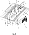
- FIG. 2 said figure shows the bottom part of the device 1 in Fig. 1 , i.e., the bottom part of outer housing 3, inner housing 4 and fan chamber 5.
- the same reference numerals are used to define respective features of device 1.
- fan chamber 5 extends over an entire length L of the device, which length L corresponds to said length mentioned above in connection with Fig. 1 .
- Fan chamber 5 is overall rectangular shape, and the air outlets 7 in side wall 8 mentioned earlier are devised in the form of a plurality of openings or slots which essentially extend over the entire length L.
- Heating elements 9 are devised in elongated form and also extend essentially over the entire length L of fan chamber 5. In this way, air flow AF2 can be heated continuously and can be used to heat space 11 (cf. Fig. 1 ) in homogenous fashion over the entire length.
- Fan 5a is located essentially in the center of fan chamber 5.
- Fan chamber 5 further comprises two identical deflecting elements 18 which have an overall triangular form with an apex 18a situated in proximity to fan 5a. From said apex 18a two deflectors 18b extend toward a respective shorter side wall 5b of fan chamber 5 and in a direction toward opposite longer side walls 8 of fan chamber 5. Said longer side walls 8 of fan chamber 5 are identical with the side walls mentioned earlier in connection with air outlet 7.
- the deflecting elements 18 are by no means limited to the special configuration shown in Fig. 2 as long as they are effective in deflecting air flow AF5 generated by fan 5a toward side walls 8 of fan chamber 5 so that the air flow may then pass through the air outlets 7 and homogenously impinge on heating elements 9, as shown in Fig. 2 .
- Reference numeral 19' in Fig. 2 denotes electronic equipment, e.g., a solid state relay (SSR), a high limit switch and a connector block.
- SSR solid state relay
- the SSR and connector block are preferably located on an aluminum plate 19" that can be located partially in said first air flow, thus providing a cooling effect for the SSR.
- Fig. 3 shows an overall prospective view of device 1.
- width W and length L of food tray 10 are visible.
- openings 13b in bottom wall 13a of salting tray (inner tray) 13 which openings are devised for letting pass air flow AF4 (cf. Fig. 1 ) there through.
- the openings 13b are distributed essentially evenly or homogenously throughout food tray 10.
- food tray 10 i.e., at least inner tray 13 is subdivided into two individual tray units 13.1, 13.2 as can be seen from separation line SL.
- Inner tray 13 may have a structured upper rim (not shown) for fixing the divider elements 14.
- said structure upper rim 13c could have a saw tooth pattern.
- the salting tray (inner tray) 13 has openings 13c, 13d along its upper edge, as shown, which are arranged in parallel series for letting pass air flow AF3 ( Fig. 1 ).
- Lower openings 13c have a bigger dimension (opening surface) than upper openings 13d.
- applicant has achieved separation of (cold) ambient air above food tray 10 and (hot) air from air flow AF3. In fact, the ambient air effectively stays on top of the hot air inside food tray 10 without mixing.
- air flow AF6 rises, thus lifting the cold air layer above food tray 10.
- Said openings 13c, 13d do overlap between the two series, meaning that an opening from a first series formed by the lower openings 13c is located where there is a gap between two adjacent openings from a second series formed by the upper openings 13d, and vice versa.
- outer housing 3 has a plurality of openings 3a in longer side walls thereof, which openings 3a are arranged over essentially the entire length of device 1 (i.e., food tray 10 or space 11). It is through these openings 3a that said first air flow (AF1, cf. Fig. 1 ) enters the device 1.
- first air flow AF1, cf. Fig. 1
- FIG. 3 further electronic or electric components 19 of the device 1, i.e., a control unit, a user interface or the like, are located outside inner housing 4 (cf. Fig. 1 ) and/or outside outer housing 3.
Landscapes
- Engineering & Computer Science (AREA)
- Mechanical Engineering (AREA)
- Food Science & Technology (AREA)
- General Engineering & Computer Science (AREA)
- Combustion & Propulsion (AREA)
- Chemical & Material Sciences (AREA)
- General Health & Medical Sciences (AREA)
- Marine Sciences & Fisheries (AREA)
- Toxicology (AREA)
- Zoology (AREA)
- Evolutionary Biology (AREA)
- Life Sciences & Earth Sciences (AREA)
- Health & Medical Sciences (AREA)
- Baking, Grill, Roasting (AREA)
- Devices For Warming Or Keeping Food Or Tableware Hot (AREA)
Description
- The invention relates to a device for storing food products at hot temperature according to the preamble of
claim 1, which device comprises, inter alia, a fan and at least one heating element installed in a vicinity of said fan, wherein the fan is used for conveying hot air provided by the heating element to at least one food tray defining a space for holding said food products. - Such devices are known in the art, e.g., for storing french fries or the like in (fast food) restaurants. Known devices use an electric heater in order to generate heat, which heat is then supplied to the food.
- The known devices suffer from relatively high energy consumption by the heater, from the fact that a housing of the device may become rather hot, which may be dangerous for a user, and from the fact that certain food stuffs may degenerate due to excessive moisture or humidity.
- Furthermore, known devices may recirculate air to conserve energy. This results in food particles to being sucked into the fan, thus creating a reliability hazard (sometimes causing a fire risk for the heating element).
- Prior art documents
US 2014/0116268 A1 andUS 4,499,818 A disclose such recirculation apparatus. - It is the object of the present invention to propose such a device which overcomes the above disadvantages and which shows reduced energy consumption, increased user safety and enhanced quality of food storage.
- This object is achieved by means of a device with the features of
claim 1. Advantageous further embodiments are defined in the sub-claims. - According to the invention, a device for storing food products at hot temperature comprises: an outer housing; an inner housing, which inner housing is at least partially contained inside said outer housing; a fan chamber defined within said inner housing, said fan chamber having at least one air inlet and one air outlet; a fan located inside said fan chamber; at least one heating element installed in a vicinity of said fan chamber; and at least one food tray defining a space for holding said food products inside said food tray; wherein a first air flow path for guiding a first air flow is defined from the outside of said outer housing to the air inlet of said fan chamber, said first flow path extending between said outer housing and said inner housing; and a second air flow path for guiding a second air flow is defined from the air outlet of said fan chamber to said space inside said at least one food tray; and the at least one heating element is located in said second air flow path. The housings and the food tray are preferably made of stainless steel or a comparable material. Furthermore, said first air flow path and said second air flow path are substantially parallel and separated by a side wall of said inner housing, whereas respective first and second air flow directions are substantially antiparallel. This has a positive impact by preheating the first air flow while at the same time providing a cooling effect for the outer housing.
- While hot temperature of the food or food product is maintained by blowing hot air heated by means of the heating element into said space (which is intended to hold the food product), at the same time moisture from the food product can be convected or drained to the outside, which is highly appreciable for some food products, such as but not limited to fries. The above-described first and second air flows, the second one of which has been heated by the heating element, can be used to preheat (cool) ambient air that is provided to the fan, thus enabling the use of heating elements with lower energy consumption. Furthermore, provision of said first and second air flows can have a cooling effect on the outer housing, thus increasing user safety.
- In an embodiment of the device according to the invention, the food tray has a length and a width, which length and width define an essentially rectangular opening for accessing said space. This enables easy access to said space for taking out food, e.g., for scooping of fries.
- In an embodiment of the device according to the invention, said heating element has a length which essentially corresponds to the length of the food tray, said seating element being arranged parallel to a length direction of said food tray. This enables homogenous heating of the entire food storage space.
- In an embodiment of the device according to the invention, the fan and/or the fan chamber is adapted for convey a major part of an air flow generated by the fan toward the heating element. In this way, any energy used for driving the fan and/or the heating element is efficiently used.
- In an embodiment of the device according to the invention, the fan chamber comprises at least one deflecting element for conveying at least part an air flow generated by the fan toward the heating element. This may further increase efficiency, as stated above.
- In yet another embodiment, the fan chamber has a top guard (i.e. a roof over the heater and fan chamber), which prevents food debris from falling onto the heating element.
- In an embodiment of the device according to the invention, said fan is a centrifugal fan. Applicant has found the use of this type of fan leads to best results in terms of energy consumption and reliability as well as required construction space. This type of fan can achieve good pressure vs volume characteristics. Having higher pressure vs volume ratio allows to equalize air flow from the fan chamber. Also, this type of fan provides low but stable (not easily damped) air flow making it more reliable during product assembly and when the unit is dirty. In most other applications on the market, tangential or axial blowers are used, that have much higher air flow volume at lower pressure.
- In an embodiment of the device according to the invention, said fan chamber is essentially rectangular in shape with corresponding side walls; and the deflecting element has a shape and is located relative to said fan so as to deflect the air flow generated by the fan toward said air outlet opening of the fan chamber, which air outlet is located in a side wall of said fan chamber. In this way, the fan chamber can be made to correspond in shape to the food tray, thus enabling homogenous heating of the (food storage) space.
- In an embodiment of the device according to the invention, the air outlet is located at a longer side wall of said fan chamber, and is preferably devised in the form of a plurality of air outlet openings or slits extending over a major part of said longer side wall. This may further increase homogeneity of the heating effect.
- In a preferred embodiment of the device according to the invention, the food tray has series of openings along its upper edge for letting pass an air flow into said space, a first series of said openings being arranged below a second series of said openings, wherein preferably said openings in said first series of openings have a bigger dimension or opening surface than said openings in said second series of openings, said openings most preferably extending over an entire length of said food tray. Said openings may overlap between the two series, meaning that an opening from said first series is located where there is a gap between two adjacent openings from said second series, and vice versa. With this particular design, applicant has achieved efficient separation of (cold) ambient air above the food tray and (hot) air inside the food tray. In fact, the ambient air effectively stays on top of the hot air inside the food tray without mixing. In the center of the device, hot air rises, thus lifting the cold air layer above the food tray.
- In an embodiment of the device according to the invention, the fan is located essentially in a center of said fan chamber. This feature may be particularly advantageous when air to be heated is to be conveyed to more than one side of the device, e.g., to opposite side walls.
- In an embodiment of the device according to the invention, there are two, preferably identical deflecting elements, each one of said deflecting elements having an apex situated in proximity to said fan and at least two deflectors extending from said apex toward a respective shorter side wall of said fan chamber in a direction toward opposite longer side walls of said fan chamber, said two deflectors preferably forming two sides of a triangular shape. This construction can be used to convey air to be heated in symmetrical fashion to both sides of the device for to achieve a particularly homogeneous heating effect.
- In an embodiment of the device according to the invention, the outer housing and the inner housing have essentially parallel side walls and essentially parallel bottom walls; and the air inlet of said fan chamber is located at the bottom wall of the fan chamber and below an entry point for ambient air into the outer housing. With this construction, cool air can be guided along a big part of the outer housing by means of said first air flow channel, thus optimizing said cooling effect and enabling the use of less powerful heating elements.
- In an embodiment of the device according to the invention, an entry point for air into said food tray is located above the air outlet of said fan chamber. This can further increase an area of thermal interaction between said first and second air flows which can have positive impact on said cooling effect and on power consumption by the heating element.
- In an embodiment of the device according to the invention, the fan chamber is located below said food tray. This has proved to be practical both in terms of required construction space and air flow configuration. Furthermore, serviceability is increased since there can be access from the top to all serviceable components.
- In an embodiment of the device according to the invention, the food tray comprises a substantially leak-proof outer tray and an inner tray, said inner tray being suspended or suspendable within said outer tray and having a number of openings at least in its bottom wall. The outer tray can be used as a crumb tray for retaining food crumbs, while the inner tray can be used as a salting tray, i.e. for salting foodstuff contained therein. Food can be placed in the inner tray and heated by air flow through said openings.
- For to enhance this latter effect, in an embodiment of the device according to the invention, a third air flow path for guiding a third air flow is defined between a side wall and/or a bottom wall of said inner tray and a side wall and/or a bottom wall of said outer tray, which third air flow is a continuation in part of said second air flow, wherein preferably said third air flow is partly anti-parallel to said second air flow.
- Said second airflow, when entering the salting tray (outer tray), can take on a horizontal direction, and air speed can be between 0,5 m/s and 2 m/s (for an embodiment of the invention, a corresponding air stream volume can be 60-120 m3/h.
- In an embodiment of the device according to the invention, said second air flow path opens to the environment of the device. In this way, part of said third air flow can be used to heat the food from above and/or to efficiently evacuate moisture, as already stated above. This also circumvents the risk of fire for the heating element, since there is no recirculation.
- In an embodiment of the device according to the invention, the outer tray comprises, at its bottom wall a deflecting element for forcing said third air flow upwards through said openings. This further enhances the food heating effect.
- During simulation of air flow in the device according to an embodiment of the invention, applicant has reached additional conclusions about said air flow to said food holding space: 1) a top air stream to the food holding space should go as parallel as possible to a bottom surface of said salting tray. 2) An air stream from the bottom wall of the salting tray upwards should be sufficient (high enough to prevent said top air stream from sucking in ambient cold air. This can achieved by gradually increasing a size and/or number of said openings in the bottom wall of the inner tray when moving towards a center thereof.
- In an embodiment of the device according to the invention, a first angle between the side walls and the bottom wall of the inner tray differs from a second angle between the side walls and the bottom wall of the outer tray, said second angle preferably being greater than said first angle. This feature may be used to enable easier access to the stored food, e.g., for scooping fries.
- In an embodiment of the device according to the invention, at least one plate-like divider element is provided for partitioning said inner tray. This enables storing of different sorts of food and prevents that the food is overmuch spread out.
- In an embodiment of the device according to the invention, said inner tray has a structured upper rim for fixing said divider element. This enables easy, reliable and reproducible fixing of the divider element.
- In an embodiment of the device according to the invention, the food tray, at least the inner tray, is separated or separable into a plurality of individual tray units. This makes handling and/or cleaning thereof easier.
- In an embodiment of the device according to the invention, the device comprises a temperature sensor, e.g. a thermostat, for controlling the heating element and/or the fan depending on a (desired) temperature in or near said space. In this way, the food can be stored at an optimum temperature. Preferably, said temperature is adjustable by a user. Fan control may be limited to a simple ON/OFF command.
- In an embodiment of the device according to the invention, said temperature sensor is located in a vicinity of the heating element within said second air flow. This provides best results.
- In an embodiment of the device according to the invention, the heating element is a ribbed heating element. Applicant has found that such a design leads to best heating results with relatively low energy consumption. Furthermore, the type of heating element has superior reliability. It is very robust and able to sustain mechanical damage better than other heater types.
- In an embodiment of the device according to the invention, at least the inner housing, the outer housing, the food tray and the fan chamber are of symmetrical form relative to a median vertical plane of the device. This allows for operation of the device from both sides, which is particularly well suited for scooping fries.
- In an embodiment of the device according to the invention, any further electronic or electric components of the device are located outside said inner housing and/or outside said outer housing. In this way, these components are easily accessible and not subjected to any excess heat. In an embodiment, the only components that are located inside the device are (temperature) sensors, heating elements, a solid state relay (SSR), the fan, a high limit switch and a connector block. SSR and connector block can be located on an aluminum plate that can be located partially in said first air flow, thus providing a cooling effect for the SSR.
- In a particular embodiment of the device, air is sucked in through openings in the upper part of the side walls of the outer housing, then it is pressed radially into the fan chamber. A particular type of perforation selected in the side walls of the fan chamber allows for an even distribution of air over the entire length of the crumb and salting trays, i.e., the food tray. The crumb tray can have a double function: it collects food remains and also provides proper air guidance serving as part of an air channel. After leaving the fan chamber, the air is preferably forced through a ribbed heating element. All other electrical components can be installed in the cold zone, e.g., outside the (inner or outer) housing. The air sucked into the fan can have a cooling effect on the outer housing and the ability to use less powerful heating elements. Air flow to the salting tray can be achieved by a perforation in the upper part of the front and back, and further perforation of the horizontal part. The crumb tray can be divided because of the easier handling and cleaning. Service access to components located below the crumb tray, i.e., the heating element, the fan, and electronic components, is possible from an upper side. Control of the air temperature is preferably achieved by means of a thermostat. All housing and channel elements can be symmetrical thus allowing operation (for example for scooping fries) from both sides.
- Further details and advantages will now be described by way of example with reference to the appended drawings.
-
Figure 1 shows a sectional view of the device according to the present invention; -
Figure 2 shows a prospective view of the bottom part of the device inFig. 1 , a particular a fan chamber thereof; and -
Figure 3 shows a prospective overall view of the device inFig. 1 . -
Fig. 1 shows a sectional view of a device for a device for storing food products at hot temperature, which device is denoted in its totality byreference numeral 1.Reference numeral 2 denotes food products which are stored in thedevice 1. Thedevice 1 comprises anouter housing 3 and aninner housing 4. Theinner housing 4 is contained inside theouter housing 3. Afan chamber 5 is defined within theinner housing 4, thefan chamber 5 having an air inlet 6 andair outlets 7. Air inlet 6 is located in abottom wall 5c offan chamber 5, whereas theair outlets 7 are located in opposingside walls 8 offan chamber 5. Afan 5a, which is devised as a centrifugal fan, is located insidefan chamber 5. In the vicinity of thefan chamber 5, i.e., on both sides thereof, there is installed aheating element 9, whichheating element 9 is devised in the form of a ripped resistance heating element which heats up under the effect of an electrical current flowing there through.Heating element 9 is located, respectively, in front of saidair outlets 7 offan chamber 5. - Above
fan chamber 5device 1 comprises a food tray generally denoted byreference numeral 10.Food tray 10 defines aspace 11 for holding saidfood products 2 insidefood tray 10.Food tray 10 consists of two separate units, i.e. anouter crumb tray 12, which is essentially leak-proof and at least oneinner salting tray 13 which is suspended withincrumb tray 12 and which has openings in itsbottom wall 13a, which openings are not visible inFig. 1 .Reference numeral 14 denotes a plate-like divider element which is used to partition saltingtray 13 into several compartments. More thanmore divider element 14 can be used. Thisdivider element 14 comprises ahandle 14a for inserting and removing saiddivider element 14. - First
air flow path 15 for guiding a first air flow (denoted by means of arrows AF1) is defined from the outside ofouter housing 3 to the air inlet 6 offan chamber 5, said firstair flow path 15 extending betweenouter housing 3 andinner housing 4. A secondair flow path 16 for guiding a second air flow AF2 is defined from theair outlets 7 offan chamber 5 to thespace 11 insidefood tray 10.Heating elements 9 are located in secondair flow path 16, i.e. are impinged on by second air flow AF2. Said secondair flow path 16 extends fromoutlet 7 offan chamber 5 upwards betweeninner housing 4 and food tray 10 (crumb tray 12) and then enters saidspace 11 from above after passing over arim 12a ofcrumb tray 12. Having passed over saidrim 12a ofcrumb tray 12, air flow AF2 is divided into two separate air flows, one of which (denoted AF3) directly entersspace 11 while another one (denoted AF4) passes betweencrumb tray 12 and saltingtray 13 and entersspace 11 through said openings inbottom wall 13a of saltingtray 13, as shown.Reference numeral 17 denotes a temperature sensor or thermostat which can be used to controlfan 5a andheating elements 9 in a suitable control circuit, not shown. Atreference numeral 12b crumb tray 12 has a protrusion in itsbottom wall 12c whichprotrusion 12b serves as a deflector for deflecting air flow AF4 upwards towardspace 11. Note that in thedevice 1 ofFig. 1 , at least theinner housing 4, theouter housing 3, thefood tray 10 and thefan chamber 5 are of symmetrical form relative to a median vertical plane MP of thedevice 1. - Arrows AF5 in
Fig. 1 denote an air flow fromfan 5a throughfan chamber 5 outwardly in the direction ofair outlets 7 and towardheating elements 9. Arrows AF6 denote an airflow leaving space 11 to the outside. While air flow AF1 is relatively cool, air flow AF2 is relatively hot due to the re-effect ofheating elements 9. This has a cooling effect onouter housing 3, while air flow AF2 has a pre-heating effect on air flow AF1, thus enabling use of blowconsumption heating elements 9. Air flow AF6 efficiently removes moisture fromspace 11, which can have a positive effect on tastes and/or quality offood products 2. -
Food tray 10 has a length and a width, only the latter of which is visible inFig. 1 . Together, said length and said width define an essentially rectangular opening for accessingspace 11 from above. - As can be further gather from
Fig. 1 , an angle between side walls (not denoted) and the bottom wall of saltingtray 13 differs from an angle between the side walls (not denoted) andbottom wall 12c of the saltingtray 12, wherein the latter angle is greater than said other angle. In the context of the present invention, the saltingtray 12 can also be referred to as outer tray, whereas thecrumb tray 13 can also be referred to as inner tray. - Referring now to
Fig. 2 , said figure shows the bottom part of thedevice 1 inFig. 1 , i.e., the bottom part ofouter housing 3,inner housing 4 andfan chamber 5. In all appended drawings, the same reference numerals are used to define respective features ofdevice 1. - As can be seen from
Fig. 2 ,fan chamber 5 extends over an entire length L of the device, which length L corresponds to said length mentioned above in connection withFig. 1 .Fan chamber 5 is overall rectangular shape, and theair outlets 7 inside wall 8 mentioned earlier are devised in the form of a plurality of openings or slots which essentially extend over the entire lengthL. Heating elements 9 are devised in elongated form and also extend essentially over the entire length L offan chamber 5. In this way, air flow AF2 can be heated continuously and can be used to heat space 11 (cf.Fig. 1 ) in homogenous fashion over the entire length.Fan 5a is located essentially in the center offan chamber 5.Fan chamber 5 further comprises twoidentical deflecting elements 18 which have an overall triangular form with an apex 18a situated in proximity tofan 5a. From saidapex 18a twodeflectors 18b extend toward a respectiveshorter side wall 5b offan chamber 5 and in a direction toward oppositelonger side walls 8 offan chamber 5. Saidlonger side walls 8 offan chamber 5 are identical with the side walls mentioned earlier in connection withair outlet 7. As would be noted by a person skilled in the art, the deflectingelements 18 are by no means limited to the special configuration shown inFig. 2 as long as they are effective in deflecting air flow AF5 generated byfan 5a towardside walls 8 offan chamber 5 so that the air flow may then pass through theair outlets 7 and homogenously impinge onheating elements 9, as shown inFig. 2 . - Reference numeral 19' in
Fig. 2 denotes electronic equipment, e.g., a solid state relay (SSR), a high limit switch and a connector block. The SSR and connector block are preferably located on analuminum plate 19" that can be located partially in said first air flow, thus providing a cooling effect for the SSR. -
Fig. 3 shows an overall prospective view ofdevice 1. InFig. 3 both, width W and length L offood tray 10 are visible. Further visible are previously mentionedopenings 13b inbottom wall 13a of salting tray (inner tray) 13, which openings are devised for letting pass air flow AF4 (cf.Fig. 1 ) there through. Theopenings 13b are distributed essentially evenly or homogenously throughoutfood tray 10. - As can be further gathered from
Fig. 3 ,food tray 10, i.e., at leastinner tray 13 is subdivided into two individual tray units 13.1, 13.2 as can be seen from separation line SL. -
Inner tray 13 may have a structured upper rim (not shown) for fixing thedivider elements 14. For example, said structureupper rim 13c could have a saw tooth pattern. - The salting tray (inner tray) 13 has
openings Fig. 1 ).Lower openings 13c have a bigger dimension (opening surface) thanupper openings 13d. Owing to this particular feature, applicant has achieved separation of (cold) ambient air abovefood tray 10 and (hot) air from air flow AF3. In fact, the ambient air effectively stays on top of the hot air insidefood tray 10 without mixing. In the center of thedevice 1, i.e., in the vicinity of line MP inFig. 1 , air flow AF6 rises, thus lifting the cold air layer abovefood tray 10. Saidopenings lower openings 13c is located where there is a gap between two adjacent openings from a second series formed by theupper openings 13d, and vice versa. - As can also be gathered from
Fig. 3 ,outer housing 3 has a plurality of openings 3a in longer side walls thereof, which openings 3a are arranged over essentially the entire length of device 1 (i.e.,food tray 10 or space 11). It is through these openings 3a that said first air flow (AF1, cf.Fig. 1 ) enters thedevice 1. - Finally, as can be gathered from
Fig. 3 , further electronic orelectric components 19 of thedevice 1, i.e., a control unit, a user interface or the like, are located outside inner housing 4 (cf.Fig. 1 ) and/or outsideouter housing 3.
Claims (26)
- Device (1) for storing food products (2) at hot temperature, comprising:an outer housing (3);an inner housing (4), which inner housing (4) is at least partially contained inside said outer housing (3);a fan chamber (5) defined within said inner housing (4), said fan chamber (5) having at least one air inlet (6) and one air outlet (7);a fan (5a) located inside said fan chamber (5);at least one heating element (9) installed in a vicinity of said fan chamber (5); andat least one food tray (10) defining a space (11) for holding said food products (2) inside said food tray (10); whereina first air flow path (15) for guiding a first air flow (AF1) is defined from the outside of said outer housing (3) to the air inlet (6) of said fan chamber (5),said first flow path (15) extending between said outer housing (3) and said inner housing (4); anda second air flow path (16) for guiding a second air flow (AF2) is defined from the air outlet (7) of said fan chamber (5) to said space (11) inside said at least one food tray (10); andthe at least one heating element (9) is located in said second air flow path (16);characterized in thatsaid first air flow path (15) and said second air flow path (16) are substantially parallel and separated by a side wall of said inner housing (4), whereas respective first and second air flow directions (AF1, AF2) are substantially antiparallel.
- The device (1) according to claim 1, wherein
the food tray (10) has a length (L) and a width (W), which length (L) and width (W) define an essentially rectangular opening for accessing said space (11). - The device (1) according to claim 2, wherein
said heating element (9) has a length which essentially corresponds to the length (L) of the food tray (10), said heating element (9) being arranged parallel to a length direction of said food tray (10). - The device (1) according to any one of claims 1 through 3, wherein
the fan (5a) and/or the fan chamber (5) is adapted for to convey a major part of an air flow (AF5) generated by the fan (5a) toward the heating element (9). - The device (1) according to any one of claims 1 through 4, wherein
the fan chamber (5) comprises at least one deflecting element (18) for conveying at least part an air flow (AF5) generated by the fan (5a) toward the heating element (9). - The device (1) according to any one of claims 1 through 5, wherein said fan (5a) is a centrifugal fan.
- The device (1) according to claims 5 and 6, whereinsaid fan chamber (5) is essentially rectangular in shape with corresponding side walls (9); andthe deflecting element (18) has a shape and is located relative to said fan (5a) so as to deflect the air flow (AF5) generated by the fan (5a) toward said air outlet (7) of the fan chamber (5), which air outlet (7) is located in a side wall (8) of said fan chamber (5).
- The device (1) according to claim 7, wherein
the air outlet (7) is located at a longer side wall (8) of said fan chamber (5), and is preferably devised in the form of a plurality of air outlet openings extending over a major part of said longer side wall (8). - The device (1) according to claim 7 or 8, wherein
the fan (5a) is located essentially in a center of said fan chamber (5). - The device (1) according to any one of claims 7 through 9, wherein
there are two, preferably identical deflecting elements (18), each one of said deflecting elements (18) having an apex (18a) situated in proximity to said fan and at least two deflectors (18b) extending from said apex (18a) toward a respective shorter side wall (5b) of said fan chamber (5) in a direction toward opposite longer side walls (8) of said fan chamber (5), said two deflectors (18b) preferably forming two sides of a triangular shape. - The device (1) according to any one of claims 1 through 10, whereinthe outer housing (3) and the inner housing (4) have essentially parallel side walls (9) and essentially parallel bottom walls (13a); andthe air inlet (6) of said fan chamber (5) is located at a bottom wall (5c) of the fan chamber (5) and below an entry point for ambient air into the outer housing (3).
- The device (1) according to any one of claims 1 through 11, wherein
an entry point for air into said food tray (10) is located above the air outlet (7) of said fan chamber (5). - The device (1) according to any one of claims 1 through 12, wherein the fan chamber (5) is located below said food tray (10).
- The device (1) according to any one of claims 1 through 13, wherein
the food tray (10) comprises a substantially leak-proof outer tray (12) and an inner tray (13), said inner tray (13) being suspended or suspendable within said outer tray (12) and having a number of openings (13b) at least in its bottom wall (13a). - The device (1) according to claim 14, wherein
a third air flow path for guiding a third air flow (AF4) is defined between a side wall and/or a bottom wall (13a) of said inner tray (13) and a side wall and/or a bottom wall (12c) of said outer tray (12), which third air flow (AF4) is a continuation in part of said second air flow (AF2), wherein preferably said third air flow (AF4) is partly anti-parallel to said second air flow (AF2). - The device (1) according to claim 14 or 15, wherein
the outer tray (12) comprises, at its bottom wall (12c) a deflecting element (12b) for forcing said third air flow (AF4) upwards through said openings (13b). - The device (1) according to any one of claims 14 through 16, wherein
a first angle between the side walls and the bottom wall (13a) of the inner tray (13) differs from a second angle between the side walls and the bottom wall (12c) of the outer tray (12), said second angle preferably being greater than said first angle. - The device (1) according to any one of claims 14 through 17, wherein
at least one plate-like divider element (14) is provided for partitioning said inner tray (13). - The device (1) according to any one of claims 1 through 18, wherein
the food tray (10) has series of openings (13c, 13d) along its upper edge for letting pass an air flow (AF2, AF3) into said space (11), a first series of said openings (13c) being arranged below a second series of said openings (13d), wherein preferably said openings (13c) in said first series of openings have a bigger dimension or opening surface than said openings (13d) in said second series of openings, said openings (13c,13d) most preferably extending over an entire length (L) of said food tray (10). - The device (1) according to any one of claims 1 through 18, wherein
the food tray (10), at least the inner tray (13) according to claims 14 through 18, is separated or separable into a plurality of individual tray units (13.1, 13.2). - The device (1) according to any one of claims 1 through 20, wherein
said second air flow path (16) opens to the environment of the device (1). - The device (1) according to any one of claims 1 through 21, further comprising a temperature sensor (17), e.g. a thermostat, for controlling the heating element (9) and/or the fan (5a) depending on a temperature in or near said space (11).
- The device (1) according to any one of claims 1 through 22, wherein
said temperature sensor (17) is located in a vicinity of the heating element (9), preferably within the second air flow. - The device (1) according to any one of claims 1 through 23, wherein
the heating element (9) is a ribbed heating element (9). - The device (1) according to any one of claims 1 through 24, wherein
at least the inner housing (4), the outer housing (3), the food tray (10) and the fan chamber (5) are of symmetrical form relative to a median vertical plane (MP) of the device (1). - The device (1) according to any one of claims 1 through 25, wherein electronic or electric components (19) of the device (1) are located outside said inner housing (4) and/or outside said outer housing (3).
Priority Applications (6)
| Application Number | Priority Date | Filing Date | Title |
|---|---|---|---|
| ES19170140T ES2972937T3 (en) | 2019-04-18 | 2019-04-18 | Device for storing food products at hot temperature |
| EP19170140.8A EP3725192B1 (en) | 2019-04-18 | 2019-04-18 | Device for storing food products at hot temperature |
| PL19170140.8T PL3725192T3 (en) | 2019-04-18 | 2019-04-18 | Device for storing food products at hot temperature |
| AU2020201586A AU2020201586B2 (en) | 2019-04-18 | 2020-03-04 | Device for storing food products at hot temperature |
| US16/835,576 US12075942B2 (en) | 2019-04-18 | 2020-03-31 | Device for storing food products at hot temperature |
| CN202010306031.5A CN111824600A (en) | 2019-04-18 | 2020-04-17 | Equipment for storing food at high temperatures |
Applications Claiming Priority (1)
| Application Number | Priority Date | Filing Date | Title |
|---|---|---|---|
| EP19170140.8A EP3725192B1 (en) | 2019-04-18 | 2019-04-18 | Device for storing food products at hot temperature |
Publications (2)
| Publication Number | Publication Date |
|---|---|
| EP3725192A1 EP3725192A1 (en) | 2020-10-21 |
| EP3725192B1 true EP3725192B1 (en) | 2024-01-17 |
Family
ID=66239837
Family Applications (1)
| Application Number | Title | Priority Date | Filing Date |
|---|---|---|---|
| EP19170140.8A Active EP3725192B1 (en) | 2019-04-18 | 2019-04-18 | Device for storing food products at hot temperature |
Country Status (6)
| Country | Link |
|---|---|
| US (1) | US12075942B2 (en) |
| EP (1) | EP3725192B1 (en) |
| CN (1) | CN111824600A (en) |
| AU (1) | AU2020201586B2 (en) |
| ES (1) | ES2972937T3 (en) |
| PL (1) | PL3725192T3 (en) |
Families Citing this family (4)
| Publication number | Priority date | Publication date | Assignee | Title |
|---|---|---|---|---|
| CN113406983A (en) * | 2021-06-22 | 2021-09-17 | 常州市科翡焊接成套设备制造有限公司 | Constant-temperature control box for carrying materials |
| GB2630266B (en) * | 2023-05-12 | 2025-05-28 | The Alan Nuttall Partnership Ltd | Dynamic air curtain control |
| WO2025049932A1 (en) * | 2023-08-30 | 2025-03-06 | Cfa Properties, Inc. | Food holder for a food holding unit |
| EP4666916B1 (en) | 2024-06-17 | 2026-07-22 | Franke Technology and Trademark Ltd | Food storing device and corresponding operating method |
Family Cites Families (16)
| Publication number | Priority date | Publication date | Assignee | Title |
|---|---|---|---|---|
| US4386558A (en) * | 1981-02-12 | 1983-06-07 | Holman J Harrison | Convection cooking equipment |
| US4499818A (en) * | 1982-09-30 | 1985-02-19 | Restaurant Technology, Inc. | Method and apparatus for holding freshly prepared fried food products |
| KR900011192Y1 (en) * | 1988-02-15 | 1990-12-22 | 이선재 | Heating device for gas griddle |
| US5276309A (en) * | 1991-03-22 | 1994-01-04 | Carter-Hoffmann Corporation | Food conditioning chest |
| US6198076B1 (en) * | 1999-11-17 | 2001-03-06 | National Presto Industries, Inc. | Convection oven |
| EP1431667B1 (en) * | 2002-12-16 | 2015-07-08 | LG Electronics, Inc. | Electric oven |
| US7109447B2 (en) * | 2004-04-08 | 2006-09-19 | Maytag Corporation | Control system for cooking appliance employing convection and radiant cooking |
| JP2008249158A (en) * | 2007-03-29 | 2008-10-16 | Mitsubishi Electric Corp | Cooker |
| US20120138593A1 (en) * | 2010-10-14 | 2012-06-07 | Franklin Jeff G | Open warming cabinet |
| US20140116268A1 (en) * | 2012-10-31 | 2014-05-01 | Duke Manufacturing Co., | Oven for heating food |
| CN203424770U (en) * | 2013-07-23 | 2014-02-12 | 张超 | Electric heating cooking device |
| CN103767562A (en) * | 2014-01-23 | 2014-05-07 | 浙江朗厨厨具有限公司 | Air frying pan |
| CN105686620A (en) * | 2016-04-22 | 2016-06-22 | 周林斌 | High-efficiency roasting pan |
| CN105816065A (en) * | 2016-06-14 | 2016-08-03 | 张毅蔚 | Air flow oven |
| CN110049699B (en) * | 2016-12-08 | 2021-05-07 | 皇家飞利浦有限公司 | Food processing equipment, controls and methods of operation |
| CN106901617A (en) * | 2017-04-21 | 2017-06-30 | 佛山酷釜电器科技有限公司 | A kind of air fryer |
-
2019
- 2019-04-18 ES ES19170140T patent/ES2972937T3/en active Active
- 2019-04-18 EP EP19170140.8A patent/EP3725192B1/en active Active
- 2019-04-18 PL PL19170140.8T patent/PL3725192T3/en unknown
-
2020
- 2020-03-04 AU AU2020201586A patent/AU2020201586B2/en active Active
- 2020-03-31 US US16/835,576 patent/US12075942B2/en active Active
- 2020-04-17 CN CN202010306031.5A patent/CN111824600A/en active Pending
Also Published As
| Publication number | Publication date |
|---|---|
| US20200329906A1 (en) | 2020-10-22 |
| CN111824600A (en) | 2020-10-27 |
| US12075942B2 (en) | 2024-09-03 |
| AU2020201586B2 (en) | 2025-06-05 |
| AU2020201586A1 (en) | 2020-11-05 |
| ES2972937T3 (en) | 2024-06-17 |
| EP3725192A1 (en) | 2020-10-21 |
| PL3725192T3 (en) | 2024-06-24 |
Similar Documents
| Publication | Publication Date | Title |
|---|---|---|
| US12075942B2 (en) | Device for storing food products at hot temperature | |
| EP3038504B1 (en) | Cooking machine | |
| KR101934903B1 (en) | Apparatus for preparing food | |
| RU2567222C2 (en) | Food preparation device | |
| US20190298106A1 (en) | An air-based cooker | |
| US7829823B2 (en) | Heated food storage and display cabinet | |
| US8437627B1 (en) | Apparatus for extending the holding time for food | |
| US20170079473A1 (en) | Oven for heating food | |
| US20110303100A1 (en) | Conveyor Toaster with Air-Cooled Panels | |
| EP2636955A1 (en) | A cooking oven provided for heat transfer by convection | |
| US20140116268A1 (en) | Oven for heating food | |
| US20260102021A1 (en) | Oven for heating food | |
| EP3084312B1 (en) | Direct-heating fan oven | |
| EP3243411B1 (en) | Display unit | |
| CA2140980A1 (en) | Conveyor oven with improved air flow | |
| US7044122B2 (en) | Direct convection oven | |
| US8635995B2 (en) | Oven having a uniform hot air flow in the preparation space | |
| CN110214469B (en) | Apparatus and system for solid state oven electronics cooling | |
| KR20210082346A (en) | Cooking appartus | |
| JP6423479B2 (en) | Electric heater for cooking | |
| WO2015092642A1 (en) | Direct-heating fan oven | |
| KR102899349B1 (en) | Induction cooktop system with airpole induction cooking zone | |
| CN218303338U (en) | Heat source overhead type fruit drying machine | |
| JP3671885B2 (en) | Electric cooker | |
| JP3863539B2 (en) | Cooker |
Legal Events
| Date | Code | Title | Description |
|---|---|---|---|
| PUAI | Public reference made under article 153(3) epc to a published international application that has entered the european phase |
Free format text: ORIGINAL CODE: 0009012 |
|
| STAA | Information on the status of an ep patent application or granted ep patent |
Free format text: STATUS: THE APPLICATION HAS BEEN PUBLISHED |
|
| AK | Designated contracting states |
Kind code of ref document: A1 Designated state(s): AL AT BE BG CH CY CZ DE DK EE ES FI FR GB GR HR HU IE IS IT LI LT LU LV MC MK MT NL NO PL PT RO RS SE SI SK SM TR |
|
| AX | Request for extension of the european patent |
Extension state: BA ME |
|
| STAA | Information on the status of an ep patent application or granted ep patent |
Free format text: STATUS: REQUEST FOR EXAMINATION WAS MADE |
|
| 17P | Request for examination filed |
Effective date: 20201026 |
|
| RBV | Designated contracting states (corrected) |
Designated state(s): AL AT BE BG CH CY CZ DE DK EE ES FI FR GB GR HR HU IE IS IT LI LT LU LV MC MK MT NL NO PL PT RO RS SE SI SK SM TR |
|
| STAA | Information on the status of an ep patent application or granted ep patent |
Free format text: STATUS: EXAMINATION IS IN PROGRESS |
|
| 17Q | First examination report despatched |
Effective date: 20230329 |
|
| GRAP | Despatch of communication of intention to grant a patent |
Free format text: ORIGINAL CODE: EPIDOSNIGR1 |
|
| STAA | Information on the status of an ep patent application or granted ep patent |
Free format text: STATUS: GRANT OF PATENT IS INTENDED |
|
| INTG | Intention to grant announced |
Effective date: 20230810 |
|
| GRAS | Grant fee paid |
Free format text: ORIGINAL CODE: EPIDOSNIGR3 |
|
| GRAA | (expected) grant |
Free format text: ORIGINAL CODE: 0009210 |
|
| STAA | Information on the status of an ep patent application or granted ep patent |
Free format text: STATUS: THE PATENT HAS BEEN GRANTED |
|
| AK | Designated contracting states |
Kind code of ref document: B1 Designated state(s): AL AT BE BG CH CY CZ DE DK EE ES FI FR GB GR HR HU IE IS IT LI LT LU LV MC MK MT NL NO PL PT RO RS SE SI SK SM TR |
|
| REG | Reference to a national code |
Ref country code: GB Ref legal event code: FG4D |
|
| REG | Reference to a national code |
Ref country code: DE Ref legal event code: R096 Ref document number: 602019045126 Country of ref document: DE |
|
| REG | Reference to a national code |
Ref country code: CH Ref legal event code: EP |
|
| REG | Reference to a national code |
Ref country code: IE Ref legal event code: FG4D |
|
| REG | Reference to a national code |
Ref country code: LT Ref legal event code: MG9D |
|
| REG | Reference to a national code |
Ref country code: NL Ref legal event code: MP Effective date: 20240117 |
|
| REG | Reference to a national code |
Ref country code: ES Ref legal event code: FG2A Ref document number: 2972937 Country of ref document: ES Kind code of ref document: T3 Effective date: 20240617 |
|
| PG25 | Lapsed in a contracting state [announced via postgrant information from national office to epo] |
Ref country code: NL Free format text: LAPSE BECAUSE OF FAILURE TO SUBMIT A TRANSLATION OF THE DESCRIPTION OR TO PAY THE FEE WITHIN THE PRESCRIBED TIME-LIMIT Effective date: 20240117 |
|
| PG25 | Lapsed in a contracting state [announced via postgrant information from national office to epo] |
Ref country code: NL Free format text: LAPSE BECAUSE OF FAILURE TO SUBMIT A TRANSLATION OF THE DESCRIPTION OR TO PAY THE FEE WITHIN THE PRESCRIBED TIME-LIMIT Effective date: 20240117 |
|
| PG25 | Lapsed in a contracting state [announced via postgrant information from national office to epo] |
Ref country code: IS Free format text: LAPSE BECAUSE OF FAILURE TO SUBMIT A TRANSLATION OF THE DESCRIPTION OR TO PAY THE FEE WITHIN THE PRESCRIBED TIME-LIMIT Effective date: 20240517 |
|
| PG25 | Lapsed in a contracting state [announced via postgrant information from national office to epo] |
Ref country code: LT Free format text: LAPSE BECAUSE OF FAILURE TO SUBMIT A TRANSLATION OF THE DESCRIPTION OR TO PAY THE FEE WITHIN THE PRESCRIBED TIME-LIMIT Effective date: 20240117 |
|
| PG25 | Lapsed in a contracting state [announced via postgrant information from national office to epo] |
Ref country code: GR Free format text: LAPSE BECAUSE OF FAILURE TO SUBMIT A TRANSLATION OF THE DESCRIPTION OR TO PAY THE FEE WITHIN THE PRESCRIBED TIME-LIMIT Effective date: 20240418 |
|
| PG25 | Lapsed in a contracting state [announced via postgrant information from national office to epo] |
Ref country code: HR Free format text: LAPSE BECAUSE OF FAILURE TO SUBMIT A TRANSLATION OF THE DESCRIPTION OR TO PAY THE FEE WITHIN THE PRESCRIBED TIME-LIMIT Effective date: 20240117 Ref country code: RS Free format text: LAPSE BECAUSE OF FAILURE TO SUBMIT A TRANSLATION OF THE DESCRIPTION OR TO PAY THE FEE WITHIN THE PRESCRIBED TIME-LIMIT Effective date: 20240417 |
|
| PG25 | Lapsed in a contracting state [announced via postgrant information from national office to epo] |
Ref country code: RS Free format text: LAPSE BECAUSE OF FAILURE TO SUBMIT A TRANSLATION OF THE DESCRIPTION OR TO PAY THE FEE WITHIN THE PRESCRIBED TIME-LIMIT Effective date: 20240417 Ref country code: NO Free format text: LAPSE BECAUSE OF FAILURE TO SUBMIT A TRANSLATION OF THE DESCRIPTION OR TO PAY THE FEE WITHIN THE PRESCRIBED TIME-LIMIT Effective date: 20240417 Ref country code: LT Free format text: LAPSE BECAUSE OF FAILURE TO SUBMIT A TRANSLATION OF THE DESCRIPTION OR TO PAY THE FEE WITHIN THE PRESCRIBED TIME-LIMIT Effective date: 20240117 Ref country code: IS Free format text: LAPSE BECAUSE OF FAILURE TO SUBMIT A TRANSLATION OF THE DESCRIPTION OR TO PAY THE FEE WITHIN THE PRESCRIBED TIME-LIMIT Effective date: 20240517 Ref country code: HR Free format text: LAPSE BECAUSE OF FAILURE TO SUBMIT A TRANSLATION OF THE DESCRIPTION OR TO PAY THE FEE WITHIN THE PRESCRIBED TIME-LIMIT Effective date: 20240117 Ref country code: GR Free format text: LAPSE BECAUSE OF FAILURE TO SUBMIT A TRANSLATION OF THE DESCRIPTION OR TO PAY THE FEE WITHIN THE PRESCRIBED TIME-LIMIT Effective date: 20240418 Ref country code: FI Free format text: LAPSE BECAUSE OF FAILURE TO SUBMIT A TRANSLATION OF THE DESCRIPTION OR TO PAY THE FEE WITHIN THE PRESCRIBED TIME-LIMIT Effective date: 20240117 Ref country code: BG Free format text: LAPSE BECAUSE OF FAILURE TO SUBMIT A TRANSLATION OF THE DESCRIPTION OR TO PAY THE FEE WITHIN THE PRESCRIBED TIME-LIMIT Effective date: 20240117 |
|
| PG25 | Lapsed in a contracting state [announced via postgrant information from national office to epo] |
Ref country code: PT Free format text: LAPSE BECAUSE OF FAILURE TO SUBMIT A TRANSLATION OF THE DESCRIPTION OR TO PAY THE FEE WITHIN THE PRESCRIBED TIME-LIMIT Effective date: 20240517 |
|
| PG25 | Lapsed in a contracting state [announced via postgrant information from national office to epo] |
Ref country code: SE Free format text: LAPSE BECAUSE OF FAILURE TO SUBMIT A TRANSLATION OF THE DESCRIPTION OR TO PAY THE FEE WITHIN THE PRESCRIBED TIME-LIMIT Effective date: 20240117 Ref country code: PT Free format text: LAPSE BECAUSE OF FAILURE TO SUBMIT A TRANSLATION OF THE DESCRIPTION OR TO PAY THE FEE WITHIN THE PRESCRIBED TIME-LIMIT Effective date: 20240517 Ref country code: LV Free format text: LAPSE BECAUSE OF FAILURE TO SUBMIT A TRANSLATION OF THE DESCRIPTION OR TO PAY THE FEE WITHIN THE PRESCRIBED TIME-LIMIT Effective date: 20240117 |
|
| PG25 | Lapsed in a contracting state [announced via postgrant information from national office to epo] |
Ref country code: DK Free format text: LAPSE BECAUSE OF FAILURE TO SUBMIT A TRANSLATION OF THE DESCRIPTION OR TO PAY THE FEE WITHIN THE PRESCRIBED TIME-LIMIT Effective date: 20240117 |
|
| PG25 | Lapsed in a contracting state [announced via postgrant information from national office to epo] |
Ref country code: SM Free format text: LAPSE BECAUSE OF FAILURE TO SUBMIT A TRANSLATION OF THE DESCRIPTION OR TO PAY THE FEE WITHIN THE PRESCRIBED TIME-LIMIT Effective date: 20240117 |
|
| REG | Reference to a national code |
Ref country code: AT Ref legal event code: UEP Ref document number: 1649978 Country of ref document: AT Kind code of ref document: T Effective date: 20240117 |
|
| REG | Reference to a national code |
Ref country code: DE Ref legal event code: R097 Ref document number: 602019045126 Country of ref document: DE |
|
| PG25 | Lapsed in a contracting state [announced via postgrant information from national office to epo] |
Ref country code: EE Free format text: LAPSE BECAUSE OF FAILURE TO SUBMIT A TRANSLATION OF THE DESCRIPTION OR TO PAY THE FEE WITHIN THE PRESCRIBED TIME-LIMIT Effective date: 20240117 Ref country code: CZ Free format text: LAPSE BECAUSE OF FAILURE TO SUBMIT A TRANSLATION OF THE DESCRIPTION OR TO PAY THE FEE WITHIN THE PRESCRIBED TIME-LIMIT Effective date: 20240117 |
|
| PG25 | Lapsed in a contracting state [announced via postgrant information from national office to epo] |
Ref country code: SK Free format text: LAPSE BECAUSE OF FAILURE TO SUBMIT A TRANSLATION OF THE DESCRIPTION OR TO PAY THE FEE WITHIN THE PRESCRIBED TIME-LIMIT Effective date: 20240117 |
|
| PG25 | Lapsed in a contracting state [announced via postgrant information from national office to epo] |
Ref country code: SM Free format text: LAPSE BECAUSE OF FAILURE TO SUBMIT A TRANSLATION OF THE DESCRIPTION OR TO PAY THE FEE WITHIN THE PRESCRIBED TIME-LIMIT Effective date: 20240117 Ref country code: SK Free format text: LAPSE BECAUSE OF FAILURE TO SUBMIT A TRANSLATION OF THE DESCRIPTION OR TO PAY THE FEE WITHIN THE PRESCRIBED TIME-LIMIT Effective date: 20240117 Ref country code: RO Free format text: LAPSE BECAUSE OF FAILURE TO SUBMIT A TRANSLATION OF THE DESCRIPTION OR TO PAY THE FEE WITHIN THE PRESCRIBED TIME-LIMIT Effective date: 20240117 Ref country code: EE Free format text: LAPSE BECAUSE OF FAILURE TO SUBMIT A TRANSLATION OF THE DESCRIPTION OR TO PAY THE FEE WITHIN THE PRESCRIBED TIME-LIMIT Effective date: 20240117 Ref country code: DK Free format text: LAPSE BECAUSE OF FAILURE TO SUBMIT A TRANSLATION OF THE DESCRIPTION OR TO PAY THE FEE WITHIN THE PRESCRIBED TIME-LIMIT Effective date: 20240117 Ref country code: CZ Free format text: LAPSE BECAUSE OF FAILURE TO SUBMIT A TRANSLATION OF THE DESCRIPTION OR TO PAY THE FEE WITHIN THE PRESCRIBED TIME-LIMIT Effective date: 20240117 |
|
| PG25 | Lapsed in a contracting state [announced via postgrant information from national office to epo] |
Ref country code: MC Free format text: LAPSE BECAUSE OF FAILURE TO SUBMIT A TRANSLATION OF THE DESCRIPTION OR TO PAY THE FEE WITHIN THE PRESCRIBED TIME-LIMIT Effective date: 20240117 |
|
| PLBE | No opposition filed within time limit |
Free format text: ORIGINAL CODE: 0009261 |
|
| STAA | Information on the status of an ep patent application or granted ep patent |
Free format text: STATUS: NO OPPOSITION FILED WITHIN TIME LIMIT |
|
| PG25 | Lapsed in a contracting state [announced via postgrant information from national office to epo] |
Ref country code: MC Free format text: LAPSE BECAUSE OF FAILURE TO SUBMIT A TRANSLATION OF THE DESCRIPTION OR TO PAY THE FEE WITHIN THE PRESCRIBED TIME-LIMIT Effective date: 20240117 |
|
| PG25 | Lapsed in a contracting state [announced via postgrant information from national office to epo] |
Ref country code: IT Free format text: LAPSE BECAUSE OF FAILURE TO SUBMIT A TRANSLATION OF THE DESCRIPTION OR TO PAY THE FEE WITHIN THE PRESCRIBED TIME-LIMIT Effective date: 20240117 |
|
| PG25 | Lapsed in a contracting state [announced via postgrant information from national office to epo] |
Ref country code: LU Free format text: LAPSE BECAUSE OF NON-PAYMENT OF DUE FEES Effective date: 20240418 |
|
| 26N | No opposition filed |
Effective date: 20241018 |
|
| REG | Reference to a national code |
Ref country code: BE Ref legal event code: MM Effective date: 20240430 |
|
| PG25 | Lapsed in a contracting state [announced via postgrant information from national office to epo] |
Ref country code: LU Free format text: LAPSE BECAUSE OF NON-PAYMENT OF DUE FEES Effective date: 20240418 Ref country code: IT Free format text: LAPSE BECAUSE OF FAILURE TO SUBMIT A TRANSLATION OF THE DESCRIPTION OR TO PAY THE FEE WITHIN THE PRESCRIBED TIME-LIMIT Effective date: 20240117 |
|
| PG25 | Lapsed in a contracting state [announced via postgrant information from national office to epo] |
Ref country code: BE Free format text: LAPSE BECAUSE OF NON-PAYMENT OF DUE FEES Effective date: 20240430 |
|
| PG25 | Lapsed in a contracting state [announced via postgrant information from national office to epo] |
Ref country code: BE Free format text: LAPSE BECAUSE OF NON-PAYMENT OF DUE FEES Effective date: 20240430 |
|
| PG25 | Lapsed in a contracting state [announced via postgrant information from national office to epo] |
Ref country code: IE Free format text: LAPSE BECAUSE OF NON-PAYMENT OF DUE FEES Effective date: 20240418 |
|
| PG25 | Lapsed in a contracting state [announced via postgrant information from national office to epo] |
Ref country code: SI Free format text: LAPSE BECAUSE OF FAILURE TO SUBMIT A TRANSLATION OF THE DESCRIPTION OR TO PAY THE FEE WITHIN THE PRESCRIBED TIME-LIMIT Effective date: 20240117 |
|
| PG25 | Lapsed in a contracting state [announced via postgrant information from national office to epo] |
Ref country code: CY Free format text: LAPSE BECAUSE OF FAILURE TO SUBMIT A TRANSLATION OF THE DESCRIPTION OR TO PAY THE FEE WITHIN THE PRESCRIBED TIME-LIMIT; INVALID AB INITIO Effective date: 20190418 |
|
| PG25 | Lapsed in a contracting state [announced via postgrant information from national office to epo] |
Ref country code: HU Free format text: LAPSE BECAUSE OF FAILURE TO SUBMIT A TRANSLATION OF THE DESCRIPTION OR TO PAY THE FEE WITHIN THE PRESCRIBED TIME-LIMIT; INVALID AB INITIO Effective date: 20190418 |
|
| PGFP | Annual fee paid to national office [announced via postgrant information from national office to epo] |
Ref country code: GB Payment date: 20260324 Year of fee payment: 8 |
|
| REG | Reference to a national code |
Ref country code: CH Ref legal event code: U11 Free format text: ST27 STATUS EVENT CODE: U-0-0-U10-U11 (AS PROVIDED BY THE NATIONAL OFFICE) Effective date: 20260501 |
|
| PG25 | Lapsed in a contracting state [announced via postgrant information from national office to epo] |
Ref country code: TR Free format text: LAPSE BECAUSE OF FAILURE TO SUBMIT A TRANSLATION OF THE DESCRIPTION OR TO PAY THE FEE WITHIN THE PRESCRIBED TIME-LIMIT Effective date: 20240117 |
|
| PGFP | Annual fee paid to national office [announced via postgrant information from national office to epo] |
Ref country code: ES Payment date: 20260520 Year of fee payment: 8 |
|
| PGFP | Annual fee paid to national office [announced via postgrant information from national office to epo] |
Ref country code: PL Payment date: 20260407 Year of fee payment: 8 |
|
| PGFP | Annual fee paid to national office [announced via postgrant information from national office to epo] |
Ref country code: DE Payment date: 20260318 Year of fee payment: 8 |
|
| PGFP | Annual fee paid to national office [announced via postgrant information from national office to epo] |
Ref country code: AT Payment date: 20260420 Year of fee payment: 8 |
|
| PGFP | Annual fee paid to national office [announced via postgrant information from national office to epo] |
Ref country code: CH Payment date: 20260501 Year of fee payment: 8 |
|
| PGFP | Annual fee paid to national office [announced via postgrant information from national office to epo] |
Ref country code: FR Payment date: 20260422 Year of fee payment: 8 |