EP3725146B1 - An assembly of two tyres for self-propelled lawn mower robots - Google Patents
An assembly of two tyres for self-propelled lawn mower robots Download PDFInfo
- Publication number
- EP3725146B1 EP3725146B1 EP20159961.0A EP20159961A EP3725146B1 EP 3725146 B1 EP3725146 B1 EP 3725146B1 EP 20159961 A EP20159961 A EP 20159961A EP 3725146 B1 EP3725146 B1 EP 3725146B1
- Authority
- EP
- European Patent Office
- Prior art keywords
- wheel
- tyre
- main wheel
- robot
- annular portion
- Prior art date
- Legal status (The legal status is an assumption and is not a legal conclusion. Google has not performed a legal analysis and makes no representation as to the accuracy of the status listed.)
- Active
Links
Images

Classifications
-
- A—HUMAN NECESSITIES
- A01—AGRICULTURE; FORESTRY; ANIMAL HUSBANDRY; HUNTING; TRAPPING; FISHING
- A01D—HARVESTING; MOWING
- A01D34/00—Mowers; Mowing apparatus of harvesters
- A01D34/006—Control or measuring arrangements
- A01D34/008—Control or measuring arrangements for automated or remotely controlled operation
-
- B—PERFORMING OPERATIONS; TRANSPORTING
- B60—VEHICLES IN GENERAL
- B60B—VEHICLE WHEELS; CASTORS; AXLES FOR WHEELS OR CASTORS; INCREASING WHEEL ADHESION
- B60B11/00—Units comprising multiple wheels arranged side by side; Wheels having more than one rim or capable of carrying more than one tyre
- B60B11/02—Units of separate wheels mounted for independent or coupled rotation
-
- B—PERFORMING OPERATIONS; TRANSPORTING
- B60—VEHICLES IN GENERAL
- B60B—VEHICLE WHEELS; CASTORS; AXLES FOR WHEELS OR CASTORS; INCREASING WHEEL ADHESION
- B60B11/00—Units comprising multiple wheels arranged side by side; Wheels having more than one rim or capable of carrying more than one tyre
- B60B11/06—Wheels with more than one rim mounted on a single wheel body
Definitions
- This invention relates to the technical sector of automatic gardening devices.
- the invention relates to a tyre for a self-propelled lawn mower robot.
- the lawn mower devices are normally used to keep lawns, gardens and grassy areas in general in optimum conditions, that is to say, for keeping the grass below a certain height in a substantially homogeneous manner over the entire cutting area.
- prior art devices use wheels, either full or rigid, which adapt poorly to operating inside work areas which have irregular surfaces, in particular if there are small obstacles on these surfaces.
- small obstacles includes all those objects or irregularities present inside the work area on which the robot can pass without detecting the need to change its forward direction.
- small obstacles may be considered as: small stones, small sticks, small piles of soil or small holes.
- the technical purpose which forms the basis of the invention is to provide an assembly of two tyres for a lawn mower robot which overcomes at least some of the above-mentioned drawbacks of the prior art.
- the aim of the invention is to provide a tyre for self-propelled lawn mower robots which is able to operate in an efficient and reliable manner even on uneven or not perfectly regular ground, in particular maintaining a correct adhesion with the ground.
- the invention describes an assembly of two tyres for self-propelled lawn mower robots which comprises for each of said two tyres an outer annular portion and an inner annular portion.
- the outer annular portion defines a tyre tread and has a cross section, in a radial plane, extending mainly along a direction substantially parallel to an axis of rotation of the tyre.
- the inner annular portion configured for coupling the tyre to a rim, is positioned at a mid-plane of the outer annular portion.
- the inner annular section has a cross-section, in a radial plane, which extends mainly along a direction substantially perpendicular to the axis of rotation of the tyre.
- this particular shape provides the tyre with a considerable flexibility and capacity for adapting to the profile of the ground on which the robot slides, allowing it to maintain an optimum adherence irrespective of any roughness or irregularities of the ground.
- the invention also relates to a wheel which comprises an assembly of two tyres according to this invention and a rim coupled to the tyre at its inner annular portion.
- the invention also relates to a self-propelled lawn mower robot which comprises a frame, movement means and cutting means.
- the movement means are associated with the frame for guiding it along a feed trajectory
- the cutting means are also associated with the frame and are also configured for cutting a turf present along the feed trajectory.
- the movement means comprise a motor; a main wheel coupled to a power pick-up of the motor; at least one auxiliary wheel which can be coupled to the main wheel to receive from it a mechanical power and coupling means configured to stably constrain the at least one auxiliary wheel to the main wheel, in such a way that the auxiliary wheel is rotationally integral with the main wheel.
- At least one of the wheels of the robot comprises a wheel according to the invention.
- the robot is designed to be fitted, using its movement means, a variable number of wheels in such a way as to exactly follow the surface of contact with the ground, thereby improving the traction if necessary.
- the main wheel and/or the at least one auxiliary wheel is a wheel comprising the assembly of two tyres according to the invention.
- the numeral 1 denotes an assembly of two tyres for a self-propelled lawn mower robots.
- Each of the tyres comprises an outer annular portion 1a and an inner annular portion 1b.
- the outer annular portion 1a defines the tread of the tyre, that is to say, it is configured to engage with the ground.
- the outer annular portion 1a has a cross-section, in a radial plane, extending mainly along a direction substantially parallel to an axis of rotation "X" of the tyre "1".
- the annular inner portion 1b is, on the other hand, configured to be able to couple the tyre 1 to a rim when it is mounted on a wheel 3.
- the inner annular portion 1b is positioned at a mid-plane "M" of the outer annular portion 1a and has a cross-section, in a radial plane, which extends mainly along a direction substantially perpendicular to the axis of rotation "X" of the tyre 1.
- the tyre has a substantially T-shaped radial cross-section, wherein the horizontal arms are defined by the outer annular portion 1a, which has the tread designed to engage the ground and the central rod is defined by the inner annular portion 1b which allows the tyre 1 to be constrained to a rim 4.
- the tyre 1 has a pair of shoulders 2, each of which is substantially S-shaped and which comprises a first portion 2a, a second portion 2b and a third portion 2c.
- the first portion 2a extends in a substantially perpendicular manner relative to the axis of rotation "X" of the tyre 1 and delimits laterally the outer annular portion 1a.
- the second portion 2b extends in a substantially perpendicular manner relative to the axis of rotation "X" of the tyre 1 and delimits laterally the inner annular portion 1b.
- the third portion 2c extends in a substantially parallel manner to the axis of rotation "X" of the tyre 1 and acts as a connector between the first portion 2a and the second portion 2b, forming also partly a wall of the outer annular portion 1a, in particular a wall facing the rim 4.
- the distance between the second portions 2b of the pair of shoulders 2 is less than 30% of the distance between the first portions 2a of the same pair of shoulders 2.
- the width of the outer annular portion 1a is significantly greater than the width adopted by the tyre 1 at the inner annular portion 1b.
- the tyre tread can easily be deformed in such a way as to adapt to the profile of the surface on which the device 10 slides and keep contact with that surface at all times.
- the tyre 1 is able to deform suitably in such a way as to follow the profile of the obstacle without a raising of the robot from the ground.
- the particular shape of the tyre 1 means that during use the portion of tyre 1 in contact with the ground deforms to adapt to the profile of the surface on which it is sliding, and then returns elastically to its original shape once it loses contact with the ground, in particular following a gradual rotation of the wheel to which it is applied.
- the assembly of two tyres 1 according to the invention makes it possible to overcome the drawbacks present in the prior art, making it possible to optimise the efficiency of the self-propelled lawn mower robot to which it is applied, adapting it to operate in the best way as a function of the specific ambient characteristics of the work area.
- the invention also relates to a wheel 3 which comprises a rim 4 and an assembly of two tyres 1, the latter being preferably made of rubber.
- each of the two tyres 1 has the technical features indicated above and is coupled to the rim 4 by its inner annular portion 1b.
- each of the two tyres 1 of each wheel is pressurised, preferably at a pressure at least equal to an atmospheric pressure.
- the wheel 3 according to the invention may be applied to a lawn mower robot of known type to make it suitable to operate correctly on any type of ground, also and in particular on ground having unevenness and irregularities.
- the invention also relates to a self-propelled lawn mower robot.
- self-propelled lawn mower robot means a robot movable in a substantially autonomous manner inside a work area to perform an operation for cutting turf present inside the area, in particular following a predetermined feed trajectory.
- the robot comprises a frame, a motor, a wheel according to the invention and cutting means.
- the frame is made, for example, of a semi-rigid material, preferably plastic, and is shaped to support the various components which form part of the robot.
- the cutting means are also associated with the frame and configured for performing a cutting operation of turf present along the feed trajectory.
- the cutting means may comprise one or more cutting blades which can be rotated, for example by means of a further power pick-up of the same motor which activates the movement device 10.
- the movement means are mounted on the frame, in such a way as to move the robot inside the working area, in particular along the feed trajectory.
- the movement means comprise a motor and a main wheel 3a coupled to a power pick-up of the motor.
- the motor may be of the electric type, powered by a battery; the latter may be of the rechargeable type.
- the main wheel 3a can be directly coupled to a power pick-up of a motor, by the action of which it is rotated determining the movement of the robot inside the work area.
- the main wheel 3a is a wheel 3 made according to the invention, that is to say, it comprises an assembly of two tyres having the technical features described above.
- the recharging of the robot which occurs at a fixed station or recharging base, is achieved by electrical coupling, in particular of the inductive type.
- the battery may also power other electrical/electronic devices provided on the lawn mower robot such as means for executing the cutting operation.
- the robot comprises at least one auxiliary wheel 3b, also preferably made according to the above-mentioned technical specifications.
- the at least one auxiliary wheel 3b can be coupled to the main wheel 3a for receiving from it a mechanical power.
- the main wheel 3a may be connected directly, for example by means of a transmission shaft or a similar system, with a power pick-up of the motor of the robot in such a way as to be rotated by the latter, whilst the at least one auxiliary wheel 3b is configured to be fixed integrally to the main wheel 3a to be rotated together with it when it is rotated by the motor.
- the at least one auxiliary wheel 3b is not connected directly to the power pick-up of the motor, but by means of the main wheel 3a which therefore acts as a unit for transmitting motion from the power pick-up to the at least one auxiliary wheel 3b.
- auxiliary wheels 3b it is possible to couple to the main wheel 3a a plurality of auxiliary wheels 3b, in this way increasing the overall surface of contact with the ground of the device 10.
- auxiliary wheels 3b For example, in the presence of muddy or wet ground, in which it is necessary to have a greater traction, it is possible to apply a plurality of auxiliary wheels 3b to the main wheel 3a, increasing the surface for contact with the ground until eliminating the risk of sliding of the wheels 3a, 3b.
- the device also comprises coupling means 5 configured for securely fixing the at least one auxiliary wheel 3b to the main wheel 3a.
- the coupling means 5 allow the wheels 3a, 3b to be fixed to each other in such a way that the at least one auxiliary wheel 3b is rotationally integral with the main wheel 3a.
- auxiliary wheels 3b can all be connected solely to the main wheel 3a, either directly or by means of further auxiliary wheels 3b, to be rotated together with it.
- the coupling means 5 are applied at a peripheral portion of the at least one auxiliary wheel 3b and of the main wheel 3a.
- both the main wheel 3a and each auxiliary wheel 3b have a plurality of through seats threaded internally and positioned in such a way that each through seat of the main wheel 3a can face a respective through seat of the auxiliary wheel 3b, and said coupling means 5 comprise a plurality of screws which can be screwed in the through seats.
- each auxiliary wheel 3b will have a first plurality of through seats, so that it can be connected to the main wheel 3a using the coupling means 5 (or to an auxiliary wheel 3b already applied to the main wheel 3a), and a second plurality of through seats so that it can be constrained to any further auxiliary wheel 3b.
- each auxiliary wheel 3b and the main wheel 3a have only a plurality of through seats in which screws of different length can be inserted depending on the number of auxiliary wheels 3b which are applied to the main wheel 3a.
- the through seats are positioned radially and equidistant from each other about the axis of rotation "X" of the wheels 3a, 3b.
- the device also comprises a protective eleemnt 6 applicable to an auxiliary wheel 3b or to the main wheel 3a.
- the protective element 6 may be applied to the outermost main wheel 3a, 3b, that is, the one furthest from the motor, in a relative lateral surface, that is to say, a surface perpendicular to its axis of rotation "X", directly facing the working area.
- the protective element 6 is configured to cover at least those portions of the lateral surface of the wheels 3a, 3b in which the connecting means 5 are applied or applicable.
- the protective element will be applied to the auxiliary wheel 3b furthest from the main wheel 3a and on a relative lateral surface directly facing the working area.
- the device 10 comprises at least one drive wheel 7 configured to further improve the traction which can be obtained from the device 10.
- the drive wheel 7 comprises a main body 7a having a substantially circular shape and a plurality of drive fingers 7b, which extend radially away from the main body 7a in such a way as to be configured to engage with the ground on which the drive wheel 7 slides.
- the drive fingers 7b are positioned circumferentially and equidistant from each other around the main body 7a in such a way as to guarantee a homogeneous and constant improvement of the traction which can be supplied by the device 10.
- the at least one drive wheel 7 is configured to be interposed between the main wheel 3a and an auxiliary wheel 3b adjacent to it or between adjacent auxiliary wheels 3b.
- the drive wheel is particularly suitable for being interposed between adjacent wheels 3a, 3b, but without excluding that it can be applied to the main wheel 3a even if no auxiliary wheel 3b is actually applied.
- the robot according to the invention is particularly efficient in operating in a wide variety of situations, since its movement means can be easily and quickly adapted to adapt to the specific conditions of the ground on which the robot must perform the cutting operation.
Landscapes
- Life Sciences & Earth Sciences (AREA)
- Environmental Sciences (AREA)
- Engineering & Computer Science (AREA)
- Mechanical Engineering (AREA)
- Harvester Elements (AREA)
- Control Of Position, Course, Altitude, Or Attitude Of Moving Bodies (AREA)
- Guiding Agricultural Machines (AREA)
Description
- This invention relates to the technical sector of automatic gardening devices.
- In particular, the invention relates to a tyre for a self-propelled lawn mower robot.
- The lawn mower devices are normally used to keep lawns, gardens and grassy areas in general in optimum conditions, that is to say, for keeping the grass below a certain height in a substantially homogeneous manner over the entire cutting area.
- There are prior art self-propelled lawn mower robots which are moved by wheels, which are connected to a suitable motor designed to rotate them, promoting in this way the movement of the robot.
- However, the Applicant has observed that the movement devices of known type have drawbacks, which adversely affect the correct movement of the robot and consequently reduce, even significantly, the efficiency in the performance of the operations for maintenance of the turf.
- In particular, prior art devices use wheels, either full or rigid, which adapt poorly to operating inside work areas which have irregular surfaces, in particular if there are small obstacles on these surfaces.
- The expression "small obstacles" includes all those objects or irregularities present inside the work area on which the robot can pass without detecting the need to change its forward direction.
- By way of example, small obstacles may be considered as: small stones, small sticks, small piles of soil or small holes.
- In these situations the impact with the obstacle could in any case cause the loss of adhesion with the ground or even an overturning of the robot.
- In this context, the technical purpose which forms the basis of the invention is to provide an assembly of two tyres for a lawn mower robot which overcomes at least some of the above-mentioned drawbacks of the prior art.
- In particular, the aim of the invention is to provide a tyre for self-propelled lawn mower robots which is able to operate in an efficient and reliable manner even on uneven or not perfectly regular ground, in particular maintaining a correct adhesion with the ground.
- Similar tyres are described in patent applications
WO03/070454(A1 US3068049(A ) andWO2005/030504(A1 ). - However, in all these prior art documents, the tyre has problems of adherence to the ground in some situations.
- The technical purpose indicated and the aims specified are substantially achieved by a tyre for a lawn mower robot comprising the technical features described in one or more of the appended claims.
- The invention describes an assembly of two tyres for self-propelled lawn mower robots which comprises for each of said two tyres an outer annular portion and an inner annular portion.
- The outer annular portion defines a tyre tread and has a cross section, in a radial plane, extending mainly along a direction substantially parallel to an axis of rotation of the tyre.
- The inner annular portion, configured for coupling the tyre to a rim, is positioned at a mid-plane of the outer annular portion.
- Moreover, the inner annular section has a cross-section, in a radial plane, which extends mainly along a direction substantially perpendicular to the axis of rotation of the tyre.
- Advantageously, this particular shape provides the tyre with a considerable flexibility and capacity for adapting to the profile of the ground on which the robot slides, allowing it to maintain an optimum adherence irrespective of any roughness or irregularities of the ground.
- The invention also relates to a wheel which comprises an assembly of two tyres according to this invention and a rim coupled to the tyre at its inner annular portion.
- The invention also relates to a self-propelled lawn mower robot which comprises a frame, movement means and cutting means.
- The movement means are associated with the frame for guiding it along a feed trajectory, the cutting means are also associated with the frame and are also configured for cutting a turf present along the feed trajectory.
- Moreover, the movement means comprise a motor; a main wheel coupled to a power pick-up of the motor; at least one auxiliary wheel which can be coupled to the main wheel to receive from it a mechanical power and coupling means configured to stably constrain the at least one auxiliary wheel to the main wheel, in such a way that the auxiliary wheel is rotationally integral with the main wheel.
- At least one of the wheels of the robot comprises a wheel according to the invention.
- Advantageously, the robot is designed to be fitted, using its movement means, a variable number of wheels in such a way as to exactly follow the surface of contact with the ground, thereby improving the traction if necessary.
- The main wheel and/or the at least one auxiliary wheel is a wheel comprising the assembly of two tyres according to the invention.
- The dependent claims, incorporated herein for reference, relate to different embodiments of the invention.
- Further features and advantages of this invention are more apparent in the detailed description below, with reference to a preferred, non-restricting, embodiment of a tyre for a self-propelled lawn mower robot as illustrated in the accompanying drawings, in which:
-
Figure 1 shows a radial cross-section of a pair of tyres according to the invention applied on respective rims; -
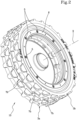
Figure 2 shows a possible embodiment of a movement device for self-propelled lawn mower robots according to the invention; -
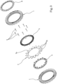
Figure 3 shows an exploded view of the device illustrated inFigure 2 . - In the accompanying drawings the
numeral 1 denotes an assembly of two tyres for a self-propelled lawn mower robots. - Each of the tyres comprises an outer
annular portion 1a and an innerannular portion 1b. - The outer
annular portion 1a defines the tread of the tyre, that is to say, it is configured to engage with the ground. - Moreover, the outer
annular portion 1a has a cross-section, in a radial plane, extending mainly along a direction substantially parallel to an axis of rotation "X" of the tyre "1". - The annular
inner portion 1b is, on the other hand, configured to be able to couple thetyre 1 to a rim when it is mounted on a wheel 3. - The inner
annular portion 1b is positioned at a mid-plane "M" of the outerannular portion 1a and has a cross-section, in a radial plane, which extends mainly along a direction substantially perpendicular to the axis of rotation "X" of thetyre 1. - In other words, the tyre has a substantially T-shaped radial cross-section, wherein the horizontal arms are defined by the outer
annular portion 1a, which has the tread designed to engage the ground and the central rod is defined by the innerannular portion 1b which allows thetyre 1 to be constrained to arim 4. - More in detail, the
tyre 1 has a pair ofshoulders 2, each of which is substantially S-shaped and which comprises afirst portion 2a, asecond portion 2b and athird portion 2c. - The
first portion 2a extends in a substantially perpendicular manner relative to the axis of rotation "X" of thetyre 1 and delimits laterally the outerannular portion 1a. - The
second portion 2b extends in a substantially perpendicular manner relative to the axis of rotation "X" of thetyre 1 and delimits laterally the innerannular portion 1b. - The
third portion 2c, on the other hand, extends in a substantially parallel manner to the axis of rotation "X" of thetyre 1 and acts as a connector between thefirst portion 2a and thesecond portion 2b, forming also partly a wall of the outerannular portion 1a, in particular a wall facing therim 4. Advantageously, the distance between thesecond portions 2b of the pair ofshoulders 2 is less than 30% of the distance between thefirst portions 2a of the same pair ofshoulders 2. - It follows that the width of the outer
annular portion 1a is significantly greater than the width adopted by thetyre 1 at the innerannular portion 1b. - In this way, a
shoulder 2 is obtained in its entirety which is extremely soft, allowing a significant deformation of the outerannular portion 1a. - In this way, the tyre tread can easily be deformed in such a way as to adapt to the profile of the surface on which the
device 10 slides and keep contact with that surface at all times. - In particular, in the presence of small obstacles, the
tyre 1 is able to deform suitably in such a way as to follow the profile of the obstacle without a raising of the robot from the ground. - Moreover, the particular shape of the
tyre 1 means that during use the portion oftyre 1 in contact with the ground deforms to adapt to the profile of the surface on which it is sliding, and then returns elastically to its original shape once it loses contact with the ground, in particular following a gradual rotation of the wheel to which it is applied. - The passage from the deformed shape to the original one generates a pulse which allows detachment of any residue, muddy in particular, or detritus, for example small stones or branches, which may remain attached to that particular portion of
tyre 1 when the robot on which it is mounted has passed above it. - In this way it is possible to guarantee that the
tyre 1 remains clean, thus preventing the accumulation of dirt which could reduce the gripping capacity on the ground. - Advantageously, the assembly of two
tyres 1 according to the invention makes it possible to overcome the drawbacks present in the prior art, making it possible to optimise the efficiency of the self-propelled lawn mower robot to which it is applied, adapting it to operate in the best way as a function of the specific ambient characteristics of the work area. - This result is obtained by introducing a tyre having a considerable flexibility which allows it to adapt and follow the profile of the surface on which it is rotated.
- The invention also relates to a wheel 3 which comprises a
rim 4 and an assembly of twotyres 1, the latter being preferably made of rubber. - In particular, each of the two
tyres 1 has the technical features indicated above and is coupled to therim 4 by its innerannular portion 1b. - Depending on the technical specifications of the robot to which the
device 10 will be applied it is also possible that each of the twotyres 1 of each wheel is pressurised, preferably at a pressure at least equal to an atmospheric pressure. - Advantageously, the wheel 3 according to the invention may be applied to a lawn mower robot of known type to make it suitable to operate correctly on any type of ground, also and in particular on ground having unevenness and irregularities.
- The invention also relates to a self-propelled lawn mower robot.
- The expression "self-propelled lawn mower robot" means a robot movable in a substantially autonomous manner inside a work area to perform an operation for cutting turf present inside the area, in particular following a predetermined feed trajectory.
- The robot comprises a frame, a motor, a wheel according to the invention and cutting means.
- The frame is made, for example, of a semi-rigid material, preferably plastic, and is shaped to support the various components which form part of the robot.
- The cutting means are also associated with the frame and configured for performing a cutting operation of turf present along the feed trajectory.
- In particular, the cutting means may comprise one or more cutting blades which can be rotated, for example by means of a further power pick-up of the same motor which activates the
movement device 10. - The movement means are mounted on the frame, in such a way as to move the robot inside the working area, in particular along the feed trajectory.
- In particular, the movement means comprise a motor and a
main wheel 3a coupled to a power pick-up of the motor. - By way of example, the motor may be of the electric type, powered by a battery; the latter may be of the rechargeable type.
- In other words, the
main wheel 3a can be directly coupled to a power pick-up of a motor, by the action of which it is rotated determining the movement of the robot inside the work area. - In particular, the
main wheel 3a is a wheel 3 made according to the invention, that is to say, it comprises an assembly of two tyres having the technical features described above. - Preferably, the recharging of the robot, which occurs at a fixed station or recharging base, is achieved by electrical coupling, in particular of the inductive type.
- Preferably, the battery may also power other electrical/electronic devices provided on the lawn mower robot such as means for executing the cutting operation.
- Moreover, the robot comprises at least one
auxiliary wheel 3b, also preferably made according to the above-mentioned technical specifications. - The at least one
auxiliary wheel 3b can be coupled to themain wheel 3a for receiving from it a mechanical power. - For this reason, the
main wheel 3a may be connected directly, for example by means of a transmission shaft or a similar system, with a power pick-up of the motor of the robot in such a way as to be rotated by the latter, whilst the at least oneauxiliary wheel 3b is configured to be fixed integrally to themain wheel 3a to be rotated together with it when it is rotated by the motor. - In other words, the at least one
auxiliary wheel 3b is not connected directly to the power pick-up of the motor, but by means of themain wheel 3a which therefore acts as a unit for transmitting motion from the power pick-up to the at least oneauxiliary wheel 3b. - Advantageously, it is possible to couple to the
main wheel 3a a plurality ofauxiliary wheels 3b, in this way increasing the overall surface of contact with the ground of thedevice 10. - In this way it is possible to modify the adherence and adherence properties of the robot depending on the particular operating conditions of the work area inside of which it must be moved.
- For example, in the presence of muddy or wet ground, in which it is necessary to have a greater traction, it is possible to apply a plurality of
auxiliary wheels 3b to themain wheel 3a, increasing the surface for contact with the ground until eliminating the risk of sliding of thewheels - Again by way of an example, in the presence, on the other hand, of more stable ground, in which a smaller surface of adhesion with the ground is sufficient to guarantee the correct movement of the robot, it is possible to reduce the number of
auxiliary wheels 3b applied, until also leaving solely applied themain wheel 3a, reducing in this way the power required from the motor to rotate them. - In this way it is possible to adapt the robot to the conditions of the ground in which it is to operate, if these change locally or over time, simply by varying the number of
auxiliary wheels 3b applied, modulating in this way the dimension of the surface of contact with the ground of thedevice 10. The device also comprises coupling means 5 configured for securely fixing the at least oneauxiliary wheel 3b to themain wheel 3a. - In particular, the coupling means 5 allow the
wheels auxiliary wheel 3b is rotationally integral with themain wheel 3a. - In this way, only the main wheel must be connected to the power pick-up of the motor, whilst the
auxiliary wheels 3b can all be connected solely to themain wheel 3a, either directly or by means of furtherauxiliary wheels 3b, to be rotated together with it. - In this way, it is possible to apply a variable number of
auxiliary wheels 3b since irrespective of the number ofauxiliary wheels 3b applied it is not necessary to modify the characteristics of the power pick-up of the motor since the latter always remains connected directly to themain wheel 3a and need not be modified to fit theauxiliary wheels 3b. - Preferably, the coupling means 5 are applied at a peripheral portion of the at least one
auxiliary wheel 3b and of themain wheel 3a. - In this way, it is possible to couple the
main wheel 3b to the motor by means of a transmission shaft, coaxial with the axis of rotation "X" of thewheels main wheel 3a and eachauxiliary wheel 3b have a plurality of through seats threaded internally and positioned in such a way that each through seat of themain wheel 3a can face a respective through seat of theauxiliary wheel 3b, and said coupling means 5 comprise a plurality of screws which can be screwed in the through seats. - In particular, each
auxiliary wheel 3b will have a first plurality of through seats, so that it can be connected to themain wheel 3a using the coupling means 5 (or to anauxiliary wheel 3b already applied to themain wheel 3a), and a second plurality of through seats so that it can be constrained to any furtherauxiliary wheel 3b. - Alternatively, each
auxiliary wheel 3b and themain wheel 3a have only a plurality of through seats in which screws of different length can be inserted depending on the number ofauxiliary wheels 3b which are applied to themain wheel 3a. - Preferably, the through seats are positioned radially and equidistant from each other about the axis of rotation "X" of the
wheels - The device also comprises a
protective eleemnt 6 applicable to anauxiliary wheel 3b or to themain wheel 3a. - In particular, the
protective element 6 may be applied to the outermostmain wheel - More specifically, the
protective element 6 is configured to cover at least those portions of the lateral surface of thewheels means 5 are applied or applicable. - If, for example, two
auxiliary wheels 3b are applied to themain wheel 3a, the protective element will be applied to theauxiliary wheel 3b furthest from themain wheel 3a and on a relative lateral surface directly facing the working area. - According to a particular embodiment, the
device 10 comprises at least one drive wheel 7 configured to further improve the traction which can be obtained from thedevice 10. - In particular, the drive wheel 7 comprises a main body 7a having a substantially circular shape and a plurality of
drive fingers 7b, which extend radially away from the main body 7a in such a way as to be configured to engage with the ground on which the drive wheel 7 slides. As may be seen in the accompanying drawings,Figures 2 and3 in particular, thedrive fingers 7b are positioned circumferentially and equidistant from each other around the main body 7a in such a way as to guarantee a homogeneous and constant improvement of the traction which can be supplied by thedevice 10. - Preferably, the at least one drive wheel 7 is configured to be interposed between the
main wheel 3a and anauxiliary wheel 3b adjacent to it or between adjacentauxiliary wheels 3b. - In other words, the drive wheel is particularly suitable for being interposed between
adjacent wheels main wheel 3a even if noauxiliary wheel 3b is actually applied. - Similarly, it is possible to apply a plurality of drive wheels 7 between each pair of
adjacent wheels auxiliary wheel 3b, that is to say, in such a way that the drive wheel 7 is directly facing the outside environment. - Advantageously, the robot according to the invention is particularly efficient in operating in a wide variety of situations, since its movement means can be easily and quickly adapted to adapt to the specific conditions of the ground on which the robot must perform the cutting operation.
Claims (12)
- An assembly of two tyres (1) for self-propelled lawn mower robots comprising:- an outer annular portion (1a) defining a tyre tread (1) and having a cross section in a radial plane extending mainly along a direction substantially parallel to an axis of rotation (X) of the tyre (1);- an inner annular portion (1b) configured to couple the tyre (1) to a rim (4) and positioned at a mid-plane of the outer annular portion (1a), said inner annular portion (1b) having a cross section in a radial plane extending mainly along a direction substantially perpendicular to said axis of rotation (X) of the tyre (1);- a pair of shoulders (2), each of said shoulders (2) having a cross section substantially in the shape of an 'S', said cross section comprising:characterised in that- a first portion (2a) substantially perpendicular to the axis of rotation (X) of the tyre (1) and designed to laterally delimit the outer annular portion (1a);- a second portion (2b) substantially perpendicular to the axis of rotation (X) of the tyre (1) and designed to laterally delimit the inner annular portion (1b);- a third portion (2c) substantially parallel to the axis of rotation (X) of the tyre (1) and designed to join the first portion (2a) with the second portion (2b);
the distance between the second portions (2b) of said pair of shoulders (2) is less than 30% of the distance between the first portions (2a) of said pair of shoulders (2). - The assembly (1) according to the preceding claim, wherein each tyre (1) is made from rubber.
- A wheel for self-propelled lawn mower robot comprising an assembly of two tyres (1) according to any one of the preceding claims and a rim (4) coupled to each of said tyres (1) respectively at the inner annular portion (1b).
- The wheel according to claim 3, wherein each tyre (1) is pressurised, preferably at a pressure at least equal to an atmospheric pressure.
- A self-propelled lawn mower robot comprising:- a frame;- a motor;- a main wheel (3a) made in accordance with claim 3 and coupled to a power pick-up of the motor;- cutting means associated with the frame and configured for performing a cutting operation of turf present along the feed trajectory.
- The robot according to claim 5, comprising:- at least one auxiliary wheel (3b), preferably made in accordance with claim 5, which can be coupled to the main wheel (3a) to receive from said main wheel (3a) a mechanical power;- coupling means (5) configured for securely fixing the at least one auxiliary wheel (3b) to said main wheel (3a), in such a way that the at least one auxiliary wheel (3b) is rotationally integral with the main wheel (3a).
- The robot according to claim 6, wherein the coupling means (5) are applicable at a peripheral portion of the at least one auxiliary wheel (3b) and of the at least one main wheel (3a).
- The robot according to claim 6 or 7, wherein the main wheel (3a) and the auxiliary wheel (3b) have a plurality of through seats threaded internally and positioned in such a way that each through seat of the main wheel (3a) can face a respective through seat of the auxiliary wheel (3b), preferably said coupling means (5) comprising a plurality of screws which can be screwed in said through seats.
- The robot according to any one of claims 6 to 9, comprising a protective element (5) which can be coupled to a lateral surface of the auxiliary wheel (3b) or of the main wheel (3a) facing directly toward a working area of the lawn mower robot, in such a way as to cover at least partly said surface.
- The robot according to any one of claims 5 to 9, comprising a drive wheel (7), said wheel having a main body (7a) substantially circular and a plurality of drive fingers (7b) extending radially away from said main body (7a).
- The robot according to claim 10, wherein said drive wheel (7) is configured to be interposed between the main wheel (3a) and an auxiliary wheel (3b) adjacent to said main wheel (3a) or between adjacent auxiliary wheels (3b).
- The robot according to claim 10 or 11, wherein said drive fingers (7b) are arranged circumferentially and equidistant from each other about the main body (7a).
Applications Claiming Priority (1)
| Application Number | Priority Date | Filing Date | Title |
|---|---|---|---|
| IT102019000006044A IT201900006044A1 (en) | 2019-04-18 | 2019-04-18 | Pneumatic for self-propelled robotic lawnmowers |
Publications (2)
| Publication Number | Publication Date |
|---|---|
| EP3725146A1 EP3725146A1 (en) | 2020-10-21 |
| EP3725146B1 true EP3725146B1 (en) | 2023-12-06 |
Family
ID=67384249
Family Applications (1)
| Application Number | Title | Priority Date | Filing Date |
|---|---|---|---|
| EP20159961.0A Active EP3725146B1 (en) | 2019-04-18 | 2020-02-28 | An assembly of two tyres for self-propelled lawn mower robots |
Country Status (2)
| Country | Link |
|---|---|
| EP (1) | EP3725146B1 (en) |
| IT (1) | IT201900006044A1 (en) |
Families Citing this family (9)
| Publication number | Priority date | Publication date | Assignee | Title |
|---|---|---|---|---|
| IT202000006541A1 (en) * | 2020-03-27 | 2021-09-27 | Vires S R L | AUTOMATIC ROBOT MOWER. |
| US12296694B2 (en) | 2021-03-10 | 2025-05-13 | Techtronic Cordless Gp | Lawnmowers |
| US12443180B2 (en) | 2021-11-10 | 2025-10-14 | Techtronic Cordless Gp | Robotic lawn mowers |
| AU2023200381A1 (en) | 2022-01-31 | 2023-08-17 | Techtronic Cordless Gp | Robotic garden tool |
| EP4270138A1 (en) | 2022-04-28 | 2023-11-01 | Techtronic Cordless GP | Creation of a virtual boundary for a robotic garden tool |
| US12472611B2 (en) | 2022-05-31 | 2025-11-18 | Techtronic Cordless Gp | Peg driver |
| EP4310621B1 (en) | 2022-07-19 | 2025-02-12 | Techtronic Cordless GP | Display for controlling robotic tool |
| AU2023206123A1 (en) | 2022-07-29 | 2024-02-15 | Techtronic Cordless Gp | Generation of a cryptography key for a robotic garden tool |
| IT202300007008A1 (en) | 2023-04-12 | 2024-10-12 | Stiga S P A In Breve Anche St S P A | Cladding, frame, assembly comprising the cladding and the frame and device comprising the assembly |
Family Cites Families (6)
| Publication number | Priority date | Publication date | Assignee | Title |
|---|---|---|---|---|
| US2635012A (en) * | 1947-11-21 | 1953-04-14 | Max E Rappaport | Vehicle wheel |
| US3068049A (en) * | 1961-06-12 | 1962-12-11 | Marion S Smith | Rim-load dual wheel kit |
| US3953075A (en) * | 1972-10-19 | 1976-04-27 | Bonomo Richard S | Auxiliary wheel mounting |
| EP1476297B1 (en) * | 2002-02-19 | 2007-04-11 | Pirelli Tyre S.p.A. | Method for manufacturing a pneumatic tyre |
| DE10343599A1 (en) * | 2003-09-20 | 2005-04-28 | Continental Ag | Vehicle tires |
| IT1393911B1 (en) * | 2009-04-16 | 2012-05-17 | Bernini | LAWN MOWERS |
-
2019
- 2019-04-18 IT IT102019000006044A patent/IT201900006044A1/en unknown
-
2020
- 2020-02-28 EP EP20159961.0A patent/EP3725146B1/en active Active
Also Published As
| Publication number | Publication date |
|---|---|
| IT201900006044A1 (en) | 2020-10-18 |
| EP3725146A1 (en) | 2020-10-21 |
Similar Documents
| Publication | Publication Date | Title |
|---|---|---|
| EP3725146B1 (en) | An assembly of two tyres for self-propelled lawn mower robots | |
| EP3571917B1 (en) | Lawn mower | |
| US20160360695A1 (en) | Cutting blade | |
| EP3723467B1 (en) | Lawnmower and method of cleaning a rolling surface of a wheel of a lawnmower | |
| US20220217904A1 (en) | Autonomous Robotic Lawnmower Comprising Suspension Means Progressively Limiting Pivotal Movement of a Cutting Unit | |
| EP3975680B1 (en) | Low impact turf wheel and wheel cleaning system | |
| EP3791708B1 (en) | Lawn mower robot | |
| EP3454707B1 (en) | Robotic cleaning device | |
| EP3716749B1 (en) | Low impact turf wheel | |
| EP3585145B1 (en) | Self-propelled robotic lawnmower comprising wheels arranged with a negative camber angle | |
| CN114599260A (en) | Wheels and Wheel-Guided Household Appliances | |
| EP3725145B1 (en) | A movement device for self-propelled lawn mower robots | |
| EP3884756A1 (en) | Automatic robotic lawn mower | |
| EP2657043B1 (en) | Wheel preferably for use on lawns and method of manufacturing same | |
| WO2018104927A3 (en) | Automomous spider lawnmower robot | |
| CN224028745U (en) | Tire for service robot, mowing robot and wheel with rim and/or wheel cover | |
| CN220615386U (en) | Tires and running wheels | |
| EP4725286A1 (en) | Cutting assembly and robotic lawnmower | |
| CN221292966U (en) | Antiskid driving wheel mechanism and mowing robot applying same | |
| RU2544907C2 (en) | Radio-controlled antiskid studs with shot pins, control system and method for radio-controlled antiskid studs with shot pins | |
| US20170166003A1 (en) | Vibration dampening assembly for a walk-behind working tool | |
| CN216535187U (en) | Wheel and cleaning equipment applying same | |
| CN212099112U (en) | Track driving mechanism of field management machine | |
| CN210502110U (en) | Mower wheel | |
| US2961025A (en) | Retread tire |
Legal Events
| Date | Code | Title | Description |
|---|---|---|---|
| PUAI | Public reference made under article 153(3) epc to a published international application that has entered the european phase |
Free format text: ORIGINAL CODE: 0009012 |
|
| STAA | Information on the status of an ep patent application or granted ep patent |
Free format text: STATUS: THE APPLICATION HAS BEEN PUBLISHED |
|
| AK | Designated contracting states |
Kind code of ref document: A1 Designated state(s): AL AT BE BG CH CY CZ DE DK EE ES FI FR GB GR HR HU IE IS IT LI LT LU LV MC MK MT NL NO PL PT RO RS SE SI SK SM TR |
|
| AX | Request for extension of the european patent |
Extension state: BA ME |
|
| STAA | Information on the status of an ep patent application or granted ep patent |
Free format text: STATUS: REQUEST FOR EXAMINATION WAS MADE |
|
| 17P | Request for examination filed |
Effective date: 20201028 |
|
| RBV | Designated contracting states (corrected) |
Designated state(s): AL AT BE BG CH CY CZ DE DK EE ES FI FR GB GR HR HU IE IS IT LI LT LU LV MC MK MT NL NO PL PT RO RS SE SI SK SM TR |
|
| STAA | Information on the status of an ep patent application or granted ep patent |
Free format text: STATUS: EXAMINATION IS IN PROGRESS |
|
| 17Q | First examination report despatched |
Effective date: 20220322 |
|
| RIC1 | Information provided on ipc code assigned before grant |
Ipc: B60B 11/02 20060101ALI20230613BHEP Ipc: A01D 34/00 20060101AFI20230613BHEP |
|
| GRAP | Despatch of communication of intention to grant a patent |
Free format text: ORIGINAL CODE: EPIDOSNIGR1 |
|
| STAA | Information on the status of an ep patent application or granted ep patent |
Free format text: STATUS: GRANT OF PATENT IS INTENDED |
|
| INTG | Intention to grant announced |
Effective date: 20230919 |
|
| GRAS | Grant fee paid |
Free format text: ORIGINAL CODE: EPIDOSNIGR3 |
|
| GRAA | (expected) grant |
Free format text: ORIGINAL CODE: 0009210 |
|
| STAA | Information on the status of an ep patent application or granted ep patent |
Free format text: STATUS: THE PATENT HAS BEEN GRANTED |
|
| AK | Designated contracting states |
Kind code of ref document: B1 Designated state(s): AL AT BE BG CH CY CZ DE DK EE ES FI FR GB GR HR HU IE IS IT LI LT LU LV MC MK MT NL NO PL PT RO RS SE SI SK SM TR |
|
| REG | Reference to a national code |
Ref country code: GB Ref legal event code: FG4D |
|
| REG | Reference to a national code |
Ref country code: CH Ref legal event code: EP |
|
| REG | Reference to a national code |
Ref country code: DE Ref legal event code: R096 Ref document number: 602020022154 Country of ref document: DE |
|
| REG | Reference to a national code |
Ref country code: IE Ref legal event code: FG4D |
|
| REG | Reference to a national code |
Ref country code: SE Ref legal event code: TRGR |
|
| REG | Reference to a national code |
Ref country code: LT Ref legal event code: MG9D |
|
| PG25 | Lapsed in a contracting state [announced via postgrant information from national office to epo] |
Ref country code: GR Free format text: LAPSE BECAUSE OF FAILURE TO SUBMIT A TRANSLATION OF THE DESCRIPTION OR TO PAY THE FEE WITHIN THE PRESCRIBED TIME-LIMIT Effective date: 20240307 |
|
| REG | Reference to a national code |
Ref country code: NL Ref legal event code: MP Effective date: 20231206 |
|
| PG25 | Lapsed in a contracting state [announced via postgrant information from national office to epo] |
Ref country code: LT Free format text: LAPSE BECAUSE OF FAILURE TO SUBMIT A TRANSLATION OF THE DESCRIPTION OR TO PAY THE FEE WITHIN THE PRESCRIBED TIME-LIMIT Effective date: 20231206 |
|
| REG | Reference to a national code |
Ref country code: AT Ref legal event code: UEP Ref document number: 1637477 Country of ref document: AT Kind code of ref document: T Effective date: 20231206 |
|
| PG25 | Lapsed in a contracting state [announced via postgrant information from national office to epo] |
Ref country code: ES Free format text: LAPSE BECAUSE OF FAILURE TO SUBMIT A TRANSLATION OF THE DESCRIPTION OR TO PAY THE FEE WITHIN THE PRESCRIBED TIME-LIMIT Effective date: 20231206 |
|
| PG25 | Lapsed in a contracting state [announced via postgrant information from national office to epo] |
Ref country code: LT Free format text: LAPSE BECAUSE OF FAILURE TO SUBMIT A TRANSLATION OF THE DESCRIPTION OR TO PAY THE FEE WITHIN THE PRESCRIBED TIME-LIMIT Effective date: 20231206 Ref country code: GR Free format text: LAPSE BECAUSE OF FAILURE TO SUBMIT A TRANSLATION OF THE DESCRIPTION OR TO PAY THE FEE WITHIN THE PRESCRIBED TIME-LIMIT Effective date: 20240307 Ref country code: ES Free format text: LAPSE BECAUSE OF FAILURE TO SUBMIT A TRANSLATION OF THE DESCRIPTION OR TO PAY THE FEE WITHIN THE PRESCRIBED TIME-LIMIT Effective date: 20231206 Ref country code: BG Free format text: LAPSE BECAUSE OF FAILURE TO SUBMIT A TRANSLATION OF THE DESCRIPTION OR TO PAY THE FEE WITHIN THE PRESCRIBED TIME-LIMIT Effective date: 20240306 |
|
| PG25 | Lapsed in a contracting state [announced via postgrant information from national office to epo] |
Ref country code: NL Free format text: LAPSE BECAUSE OF FAILURE TO SUBMIT A TRANSLATION OF THE DESCRIPTION OR TO PAY THE FEE WITHIN THE PRESCRIBED TIME-LIMIT Effective date: 20231206 |
|
| PG25 | Lapsed in a contracting state [announced via postgrant information from national office to epo] |
Ref country code: RS Free format text: LAPSE BECAUSE OF FAILURE TO SUBMIT A TRANSLATION OF THE DESCRIPTION OR TO PAY THE FEE WITHIN THE PRESCRIBED TIME-LIMIT Effective date: 20231206 Ref country code: NO Free format text: LAPSE BECAUSE OF FAILURE TO SUBMIT A TRANSLATION OF THE DESCRIPTION OR TO PAY THE FEE WITHIN THE PRESCRIBED TIME-LIMIT Effective date: 20240306 Ref country code: NL Free format text: LAPSE BECAUSE OF FAILURE TO SUBMIT A TRANSLATION OF THE DESCRIPTION OR TO PAY THE FEE WITHIN THE PRESCRIBED TIME-LIMIT Effective date: 20231206 Ref country code: LV Free format text: LAPSE BECAUSE OF FAILURE TO SUBMIT A TRANSLATION OF THE DESCRIPTION OR TO PAY THE FEE WITHIN THE PRESCRIBED TIME-LIMIT Effective date: 20231206 Ref country code: HR Free format text: LAPSE BECAUSE OF FAILURE TO SUBMIT A TRANSLATION OF THE DESCRIPTION OR TO PAY THE FEE WITHIN THE PRESCRIBED TIME-LIMIT Effective date: 20231206 |
|
| PG25 | Lapsed in a contracting state [announced via postgrant information from national office to epo] |
Ref country code: IS Free format text: LAPSE BECAUSE OF FAILURE TO SUBMIT A TRANSLATION OF THE DESCRIPTION OR TO PAY THE FEE WITHIN THE PRESCRIBED TIME-LIMIT Effective date: 20240406 |
|
| P01 | Opt-out of the competence of the unified patent court (upc) registered |
Free format text: CASE NUMBER: APP_33083/2024 Effective date: 20240603 |
|
| PG25 | Lapsed in a contracting state [announced via postgrant information from national office to epo] |
Ref country code: CZ Free format text: LAPSE BECAUSE OF FAILURE TO SUBMIT A TRANSLATION OF THE DESCRIPTION OR TO PAY THE FEE WITHIN THE PRESCRIBED TIME-LIMIT Effective date: 20231206 |
|
| PG25 | Lapsed in a contracting state [announced via postgrant information from national office to epo] |
Ref country code: SK Free format text: LAPSE BECAUSE OF FAILURE TO SUBMIT A TRANSLATION OF THE DESCRIPTION OR TO PAY THE FEE WITHIN THE PRESCRIBED TIME-LIMIT Effective date: 20231206 |
|
| PG25 | Lapsed in a contracting state [announced via postgrant information from national office to epo] |
Ref country code: SM Free format text: LAPSE BECAUSE OF FAILURE TO SUBMIT A TRANSLATION OF THE DESCRIPTION OR TO PAY THE FEE WITHIN THE PRESCRIBED TIME-LIMIT Effective date: 20231206 Ref country code: SK Free format text: LAPSE BECAUSE OF FAILURE TO SUBMIT A TRANSLATION OF THE DESCRIPTION OR TO PAY THE FEE WITHIN THE PRESCRIBED TIME-LIMIT Effective date: 20231206 Ref country code: RO Free format text: LAPSE BECAUSE OF FAILURE TO SUBMIT A TRANSLATION OF THE DESCRIPTION OR TO PAY THE FEE WITHIN THE PRESCRIBED TIME-LIMIT Effective date: 20231206 Ref country code: IS Free format text: LAPSE BECAUSE OF FAILURE TO SUBMIT A TRANSLATION OF THE DESCRIPTION OR TO PAY THE FEE WITHIN THE PRESCRIBED TIME-LIMIT Effective date: 20240406 Ref country code: EE Free format text: LAPSE BECAUSE OF FAILURE TO SUBMIT A TRANSLATION OF THE DESCRIPTION OR TO PAY THE FEE WITHIN THE PRESCRIBED TIME-LIMIT Effective date: 20231206 Ref country code: CZ Free format text: LAPSE BECAUSE OF FAILURE TO SUBMIT A TRANSLATION OF THE DESCRIPTION OR TO PAY THE FEE WITHIN THE PRESCRIBED TIME-LIMIT Effective date: 20231206 |
|
| PG25 | Lapsed in a contracting state [announced via postgrant information from national office to epo] |
Ref country code: PL Free format text: LAPSE BECAUSE OF FAILURE TO SUBMIT A TRANSLATION OF THE DESCRIPTION OR TO PAY THE FEE WITHIN THE PRESCRIBED TIME-LIMIT Effective date: 20231206 Ref country code: PT Free format text: LAPSE BECAUSE OF FAILURE TO SUBMIT A TRANSLATION OF THE DESCRIPTION OR TO PAY THE FEE WITHIN THE PRESCRIBED TIME-LIMIT Effective date: 20240408 |
|
| PG25 | Lapsed in a contracting state [announced via postgrant information from national office to epo] |
Ref country code: PT Free format text: LAPSE BECAUSE OF FAILURE TO SUBMIT A TRANSLATION OF THE DESCRIPTION OR TO PAY THE FEE WITHIN THE PRESCRIBED TIME-LIMIT Effective date: 20240408 Ref country code: PL Free format text: LAPSE BECAUSE OF FAILURE TO SUBMIT A TRANSLATION OF THE DESCRIPTION OR TO PAY THE FEE WITHIN THE PRESCRIBED TIME-LIMIT Effective date: 20231206 |
|
| REG | Reference to a national code |
Ref country code: DE Ref legal event code: R097 Ref document number: 602020022154 Country of ref document: DE |
|
| PG25 | Lapsed in a contracting state [announced via postgrant information from national office to epo] |
Ref country code: MC Free format text: LAPSE BECAUSE OF FAILURE TO SUBMIT A TRANSLATION OF THE DESCRIPTION OR TO PAY THE FEE WITHIN THE PRESCRIBED TIME-LIMIT Effective date: 20231206 |
|
| REG | Reference to a national code |
Ref country code: CH Ref legal event code: PL |
|
| PG25 | Lapsed in a contracting state [announced via postgrant information from national office to epo] |
Ref country code: DK Free format text: LAPSE BECAUSE OF FAILURE TO SUBMIT A TRANSLATION OF THE DESCRIPTION OR TO PAY THE FEE WITHIN THE PRESCRIBED TIME-LIMIT Effective date: 20231206 |
|
| PLBE | No opposition filed within time limit |
Free format text: ORIGINAL CODE: 0009261 |
|
| STAA | Information on the status of an ep patent application or granted ep patent |
Free format text: STATUS: NO OPPOSITION FILED WITHIN TIME LIMIT |
|
| PG25 | Lapsed in a contracting state [announced via postgrant information from national office to epo] |
Ref country code: LU Free format text: LAPSE BECAUSE OF NON-PAYMENT OF DUE FEES Effective date: 20240228 |
|
| PG25 | Lapsed in a contracting state [announced via postgrant information from national office to epo] |
Ref country code: CH Free format text: LAPSE BECAUSE OF NON-PAYMENT OF DUE FEES Effective date: 20240229 |
|
| PG25 | Lapsed in a contracting state [announced via postgrant information from national office to epo] |
Ref country code: SI Free format text: LAPSE BECAUSE OF FAILURE TO SUBMIT A TRANSLATION OF THE DESCRIPTION OR TO PAY THE FEE WITHIN THE PRESCRIBED TIME-LIMIT Effective date: 20231206 |
|
| PG25 | Lapsed in a contracting state [announced via postgrant information from national office to epo] |
Ref country code: SI Free format text: LAPSE BECAUSE OF FAILURE TO SUBMIT A TRANSLATION OF THE DESCRIPTION OR TO PAY THE FEE WITHIN THE PRESCRIBED TIME-LIMIT Effective date: 20231206 Ref country code: LU Free format text: LAPSE BECAUSE OF NON-PAYMENT OF DUE FEES Effective date: 20240228 Ref country code: DK Free format text: LAPSE BECAUSE OF FAILURE TO SUBMIT A TRANSLATION OF THE DESCRIPTION OR TO PAY THE FEE WITHIN THE PRESCRIBED TIME-LIMIT Effective date: 20231206 Ref country code: CH Free format text: LAPSE BECAUSE OF NON-PAYMENT OF DUE FEES Effective date: 20240229 |
|
| 26N | No opposition filed |
Effective date: 20240909 |
|
| GBPC | Gb: european patent ceased through non-payment of renewal fee |
Effective date: 20240306 |
|
| PG25 | Lapsed in a contracting state [announced via postgrant information from national office to epo] |
Ref country code: GB Free format text: LAPSE BECAUSE OF NON-PAYMENT OF DUE FEES Effective date: 20240306 |
|
| PG25 | Lapsed in a contracting state [announced via postgrant information from national office to epo] |
Ref country code: IE Free format text: LAPSE BECAUSE OF NON-PAYMENT OF DUE FEES Effective date: 20240228 |
|
| PG25 | Lapsed in a contracting state [announced via postgrant information from national office to epo] |
Ref country code: IE Free format text: LAPSE BECAUSE OF NON-PAYMENT OF DUE FEES Effective date: 20240228 Ref country code: GB Free format text: LAPSE BECAUSE OF NON-PAYMENT OF DUE FEES Effective date: 20240306 |
|
| PG25 | Lapsed in a contracting state [announced via postgrant information from national office to epo] |
Ref country code: CY Free format text: LAPSE BECAUSE OF FAILURE TO SUBMIT A TRANSLATION OF THE DESCRIPTION OR TO PAY THE FEE WITHIN THE PRESCRIBED TIME-LIMIT; INVALID AB INITIO Effective date: 20200228 |
|
| PG25 | Lapsed in a contracting state [announced via postgrant information from national office to epo] |
Ref country code: HU Free format text: LAPSE BECAUSE OF FAILURE TO SUBMIT A TRANSLATION OF THE DESCRIPTION OR TO PAY THE FEE WITHIN THE PRESCRIBED TIME-LIMIT; INVALID AB INITIO Effective date: 20200228 |
|
| PG25 | Lapsed in a contracting state [announced via postgrant information from national office to epo] |
Ref country code: FI Free format text: LAPSE BECAUSE OF FAILURE TO SUBMIT A TRANSLATION OF THE DESCRIPTION OR TO PAY THE FEE WITHIN THE PRESCRIBED TIME-LIMIT Effective date: 20231207 |
|
| PG25 | Lapsed in a contracting state [announced via postgrant information from national office to epo] |
Ref country code: TR Free format text: LAPSE BECAUSE OF FAILURE TO SUBMIT A TRANSLATION OF THE DESCRIPTION OR TO PAY THE FEE WITHIN THE PRESCRIBED TIME-LIMIT Effective date: 20231206 |
|
| PGFP | Annual fee paid to national office [announced via postgrant information from national office to epo] |
Ref country code: SE Payment date: 20260223 Year of fee payment: 7 |
|
| PGFP | Annual fee paid to national office [announced via postgrant information from national office to epo] |
Ref country code: DE Payment date: 20260220 Year of fee payment: 7 |
|
| PGFP | Annual fee paid to national office [announced via postgrant information from national office to epo] |
Ref country code: AT Payment date: 20260218 Year of fee payment: 7 |
|
| PGFP | Annual fee paid to national office [announced via postgrant information from national office to epo] |
Ref country code: BE Payment date: 20260220 Year of fee payment: 7 Ref country code: IT Payment date: 20260226 Year of fee payment: 7 |
|
| PGFP | Annual fee paid to national office [announced via postgrant information from national office to epo] |
Ref country code: FR Payment date: 20260227 Year of fee payment: 7 |