EP3724732B1 - Method and a system for reducing vibrations in a mechanical processing for removal of chippings - Google Patents
Method and a system for reducing vibrations in a mechanical processing for removal of chippings Download PDFInfo
- Publication number
- EP3724732B1 EP3724732B1 EP18816259.8A EP18816259A EP3724732B1 EP 3724732 B1 EP3724732 B1 EP 3724732B1 EP 18816259 A EP18816259 A EP 18816259A EP 3724732 B1 EP3724732 B1 EP 3724732B1
- Authority
- EP
- European Patent Office
- Prior art keywords
- operating speed
- value
- frequency
- vibration
- reduction strategy
- Prior art date
- Legal status (The legal status is an assumption and is not a legal conclusion. Google has not performed a legal analysis and makes no representation as to the accuracy of the status listed.)
- Active
Links
Images

Classifications
-
- G—PHYSICS
- G05—CONTROLLING; REGULATING
- G05B—CONTROL OR REGULATING SYSTEMS IN GENERAL; FUNCTIONAL ELEMENTS OF SUCH SYSTEMS; MONITORING OR TESTING ARRANGEMENTS FOR SUCH SYSTEMS OR ELEMENTS
- G05B19/00—Program-control systems
- G05B19/02—Program-control systems electric
- G05B19/18—Numerical control [NC], i.e. automatically operating machines, in particular machine tools, e.g. in a manufacturing environment, so as to execute positioning, movement or co-ordinated operations by means of program data in numerical form
- G05B19/19—Numerical control [NC], i.e. automatically operating machines, in particular machine tools, e.g. in a manufacturing environment, so as to execute positioning, movement or co-ordinated operations by means of program data in numerical form characterised by positioning or contouring control systems, e.g. to control position from one programmed point to another or to control movement along a programmed continuous path
-
- G—PHYSICS
- G05—CONTROLLING; REGULATING
- G05B—CONTROL OR REGULATING SYSTEMS IN GENERAL; FUNCTIONAL ELEMENTS OF SUCH SYSTEMS; MONITORING OR TESTING ARRANGEMENTS FOR SUCH SYSTEMS OR ELEMENTS
- G05B19/00—Program-control systems
- G05B19/02—Program-control systems electric
- G05B19/18—Numerical control [NC], i.e. automatically operating machines, in particular machine tools, e.g. in a manufacturing environment, so as to execute positioning, movement or co-ordinated operations by means of program data in numerical form
- G05B19/182—Numerical control [NC], i.e. automatically operating machines, in particular machine tools, e.g. in a manufacturing environment, so as to execute positioning, movement or co-ordinated operations by means of program data in numerical form characterised by the machine tool function, e.g. thread cutting, cam making, tool direction control
-
- G—PHYSICS
- G05—CONTROLLING; REGULATING
- G05B—CONTROL OR REGULATING SYSTEMS IN GENERAL; FUNCTIONAL ELEMENTS OF SUCH SYSTEMS; MONITORING OR TESTING ARRANGEMENTS FOR SUCH SYSTEMS OR ELEMENTS
- G05B19/00—Program-control systems
- G05B19/02—Program-control systems electric
- G05B19/18—Numerical control [NC], i.e. automatically operating machines, in particular machine tools, e.g. in a manufacturing environment, so as to execute positioning, movement or co-ordinated operations by means of program data in numerical form
- G05B19/414—Structure of the control system, e.g. common controller or multiprocessor systems, interface to servo, programmable interface controller
-
- G—PHYSICS
- G05—CONTROLLING; REGULATING
- G05B—CONTROL OR REGULATING SYSTEMS IN GENERAL; FUNCTIONAL ELEMENTS OF SUCH SYSTEMS; MONITORING OR TESTING ARRANGEMENTS FOR SUCH SYSTEMS OR ELEMENTS
- G05B2219/00—Program-control systems
- G05B2219/30—Nc systems
- G05B2219/37—Measurements
- G05B2219/37346—Cutting, chip quality
-
- G—PHYSICS
- G05—CONTROLLING; REGULATING
- G05B—CONTROL OR REGULATING SYSTEMS IN GENERAL; FUNCTIONAL ELEMENTS OF SUCH SYSTEMS; MONITORING OR TESTING ARRANGEMENTS FOR SUCH SYSTEMS OR ELEMENTS
- G05B2219/00—Program-control systems
- G05B2219/30—Nc systems
- G05B2219/37—Measurements
- G05B2219/37351—Detect vibration, ultrasound
-
- G—PHYSICS
- G05—CONTROLLING; REGULATING
- G05B—CONTROL OR REGULATING SYSTEMS IN GENERAL; FUNCTIONAL ELEMENTS OF SUCH SYSTEMS; MONITORING OR TESTING ARRANGEMENTS FOR SUCH SYSTEMS OR ELEMENTS
- G05B2219/00—Program-control systems
- G05B2219/30—Nc systems
- G05B2219/41—Servomotor, servo controller till figures
- G05B2219/41229—Adding a vibration, noise signal to reference signal of position, speed or acceleration
Definitions
- This invention relates to a method and a system for reducing vibrations in a mechanical processing for removal of chippings.
- the invention relates to a method and a system for reducing regenerative instability phenomena, commonly known as regenerative chatter, originating from the dynamic interaction between a workpiece being processed and a machine tool, such as, for example, a milling machine.
- regenerative chatter regenerative instability phenomena
- the regenerative chatter phenomenon has been known for some time in the sector for the removal of chippings and, even though it has been dealt with to a certain extent, it is still currently difficult to resolve.
- the literature teaches how it is possible to treat these phenomena by means of two different strategies, usually alternative to each other, for reducing vibrations, both focussed on the variation of the operating speed in the search for a value or condition which stabilises the processing.
- the teaching of the theoretical prior art is to analyse the behaviour of the machine during the performance of a specific processing by means of the trend of what is commonly called the "lobe diagram", representing the lobed curve which ideally identifies a stable region, characterised by the stable processing, with respect to one in which unstable processing is associated as a function of both the speed of rotation of the mandrel (X-axis) and the depth of the pass (Y-axis).
- the aim of this invention is to provide a method and a system for reducing vibrations originating in a mechanical processing for the removal of chippings which can overcome the above-mentioned drawbacks of the prior art.
- the aim of the invention is to provide a method and a system for reducing vibrations in a mechanical processing for the removal of chippings which is particularly robust and efficient.
- the aim of this invention is to provide a method and a system for reducing vibrations in a mechanical processing for the removal of chippings which is easy to set up and install.
- the method for reducing vibrations is, as mentioned, used during a processing for the removal of chippings, preferably milling, carried out by a machine tool having a mandrel rotating at a relative operating speed on which is mounted a predetermined tool equipped with one or more cutting tools (defining a plurality of frequencies which are characteristic of the process).
- the method comprises monitoring the vibration which arises from the contact between the tool and a workpiece being processed (that is to say, the vibrations originating during the processing) and detecting the occurrence of a regenerative vibratory phenomenon.
- the detection of the vibratory regenerative phenomenon is performed by measuring, in the vibration, a frequency content which is not correlated (not associated) with the characteristic frequencies of the process (predetermined as a function of the structure of the machine and the processing).
- the detection may comprise a comparison of the vibration detected with a pre-set limit value, which, when it is exceeded, identifies the occurrence of the by regenerative vibratory phenomenon.
- the assessment of the intensity of the vibration is performed in frequency terms, that is to say, by analysing the frequency spectrum of the vibration signal (analysing the vibration signal in the frequency domain).
- the frequency (main) of the vibratory phenomenon is calculated.
- a value representing a resonance frequency is preferably estimated on the basis of the frequency value (main) of the vibratory phenomenon.
- At least one threshold value is subsequently (or simultaneously) determined on the basis of the value representing a resonance frequency.
- the threshold value is preferably a value comparable with the operating speed (i.e. rotation of the mandrel)
- the method comprises comparing the real-time value of the operating speed of the mandrel with the threshold value.
- the method then comprises reducing the intensity of the vibratory phenomenon by the performance of a first reduction strategy SST and a second reduction strategy SSV as a function of the result of comparison.
- the method comprises performing the first control strategy, based on a correction of the operating speed when the operating speed of the mandrel is greater than the threshold value.
- the method comprises performing a second reduction strategy SSV, based on a continuous modulation which imparts an oscillation to the speed around the value of the operating speed when the operating speed is less than the threshold value.
- the system is robust and able to adapt to the individual characteristics of the processing and of the machine, thus being particularly efficient.
- the determination of the threshold value comprises calculating a stable operating speed as a function of the resonance frequency of the machine.
- the stable operating speed correspond to that of the first stability lobe of the lobe diagram (i.e. maximum speed) and is calculated as a function of the resonance frequency.
- the value representing the resonance frequency of the machine corresponds to the measured frequency of the vibratory phenomenon, which clearly considerably simplifies the determination of the above-mentioned stable operating speed.
- the stable operating speed is then divided by a predetermined number, preferably whole and more preferably equal to five, in order to calculate the threshold value.
- the threshold value divides the range of operating speeds of the machine into at least a first range, which corresponds to low operating speeds, and at least a second range, which corresponds to high operating speeds.
- the method allows the machine to autonomously distinguish the ideal type of intervention (i.e. reduction strategy) as a function of the operating speed of the machine.
- This invention also relates to a system for reducing vibrations which operates according to the method which is also the object of the invention.
- the system comprises:
- the processing unit is configured to compare the signal representing the vibration with one or more pre-set reference parameters
- reference parameters may be defined by the characteristics frequencies (already mentioned above) or, alternatively, one or more limit values (or thresholds).
- the method for reducing vibrations comprises:
- the first and second reduction strategies are similar to those described above.
- the first reduction strategy SST comprises a correction of the operating speed, increasing or decreasing, and is actuated by the processing unit when the real-time value of the operating speed of the tool (or of the mandrel) exceeds the threshold value.
- the second reduction strategy SSV is on the other hand based on a continuous modulation which imparts an oscillation to the operating speed around the real-time value of the operating speed and is actuated by the processing unit when the real-time value of the operating speed of the mandrel (or of the tool) is less than the threshold value.
- the processing unit is configured to perform both the first and the second reduction strategy in an iterative fashion for a predetermined number of cycles/iterations.
- the processing unit is preferably configured to stop the adopted reduction strategy.
- stop means that the parameters of the strategy are fixed to the last values available or to the values for which the lowest intensity of the vibration has been detected.
- the system preferably comprises a user interface module associated with the processing unit and configured to allow the user to set the parameters for controlling the first and second reduction strategy according to the particular needs.
- the user can set up the parameters for controlling the strategies according to the relative experience in such a way as to maximise the effectiveness, reducing as much as possible the number of iteration necessary to reach the stability.
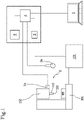
- the numeral 1 denotes a system for reducing vibrations in a mechanical processing for removal of chippings according to the invention.
- the system 1 is applied (applicable) to a machine tool 100, preferably to a milling cutter.
- the machine tool 100 generically comprises a part holding device 101, a mandrel 102 rotating at a relative operating speed ⁇ L and movable towards and away from the part holding device 101 according to one or more working axes.
- a predetermined tool 103 equipped with one or more cutters is mounted on the mandrel 102, wherein the type and the number of cutters is a function of the processing to be performed.
- the machine 100 comprises a control unit 104.
- the control unit 104 is configured to receive from suitable sensors the parameters representative of the machine (positions, torques, currents, temperatures, etc.) and to control the movements along the axes, in terms of torque, speed and resulting position and as a function of a predetermined work cycle.
- the system 1 is configured to interface with the machine tool 100, or, if necessary, to be integrated with it, in order to actuate a method for reducing vibrations, preferably a method also according to the invention.
- the system 1 preferably comprises sensor means 2 configured for monitoring the vibration which arises from the interaction between the tool 103 and a workpiece "WP" being processed.
- the sensor means 2 are also prepared for providing a signal "S1" representing the vibration.
- the sensor means 2 are configured to detect the vibration in accelerometer terms, that is to say, the mechanical oscillation of the tool or the mandrel or the machine, and/or in acoustic terms, that is to say, the generation of a sound wave by the vibrating of the tool or workpiece.
- the sensor means 2 comprise an accelerometer 2a, to be associated with the mandrel 102 of the machine tool 100 and configured for identifying the vibrations which are transmitted by the tool 104 to the mandrel 102.
- this type of sensor is particularly effective in measuring vibrations arising with "squat" tools, which are able to transmit all or part of the vibration to the structure of the machine, in particular to the mandrel 102 and to the machine 100.
- the sensor means 2 comprise a microphone 2b, preferably a hydrophone, positioned at a predetermined distance from the tool 104 so as to pick up the oscillations of the tool, that is to say, the sound waves generated by the vibration of the tool.
- this type of sensor is particularly effective in measuring vibrations arising with "slim" tools, wherein the vibration is transformed mainly into an oscillation of the tool/cutter itself.
- the sensor means 2 comprise both the accelerometer 2a (or the accelerometers) and the microphone 2b.
- the system 1 also comprises an interface 3 (or interface module) designed to be put in communication with the control unit 104 of the machine tool 100.
- the interface 3 is configured to exchange signals with the control unit 104, both to receive signals representing the fundamental quantities of the processing (operating speed ⁇ L , working torque, position, etc.) and to send to the control unit 104 signals representing a reduction strategy, specifically a "target" operating speed.
- the interface 3 is placed in direct communication also with the sensor means 2, in such a way as to receive the signal S1 from them.
- the system 1 also comprises a processing unit 4 associated with the sensor means 2 and the interface 3 to exchange signals with it.
- the processing unit 4 is designed to compare together the signals received from the sensor means 2 and the interface 3 and identify, as a function of the comparison, at least one processing condition started by the machine tool 100.
- the processing unit 4 is configured to compare together the signals received from the sensor means 2 and/or from the interface 3 with a set of corresponding reference parameters representing at least one operating status of the machine, the operating state corresponding at least with a processing condition.
- the processing unit 4 is programmed to identify the operating status of the machine and in particular at least a single processing condition in which regenerative vibratory phenomena could arise.
- the processing unit 4 is configured for identifying a plurality of operating conditions of the machine tool 100, including the above-mentioned processing condition and at least a condition (status) at the entrance of the workpiece.
- the processing unit 4 is configured to receive the signal "S1" representing the vibration from the sensor means 2 (if necessary, through the interface 3) and is configured to compare the signal with one or more reference parameters.
- the comparison is performed in the range of the frequencies.
- the processing unit 4 is preferably configured to transform the signal "S1" representing the vibration, acquired in a time domain, into a frequency domain (for example, Fourier transform), identifying the frequencies in play.
- the processing unit 4 detects that the processing frequencies are uncorrelated (or not associated) with the characteristic frequencies of the process (predetermined), then it measures the occurrence of a regenerative vibratory phenomenon.
- the processing unit could carry out the comparison in the time domain, identifying the maximum values of the vibration signal as a value representing the oscillation amplitude.
- the occurrence of the regenerative vibratory phenomenon is detected when the intensity of the vibration (in terms of energy or amplitude) exceeds a pre-set limit value.
- the processing unit 4 is configured to activate a method for reducing the vibration.
- the processing unit is configured to activate the method for reducing the vibration only when the started processing condition is identified.
- the processing unit 4 is configured for identifying (or calculating the frequency of the vibratory phenomenon (fC) the frequency of the vibratory phenomenon fc detected.
- the frequency may already have been identified in the comparing step or be calculated during this step.
- the frequency of the vibratory phenomenon fc is preferably calculated by transforming the vibration signals in the frequency domain and identifying the frequency value for which there are the greatest amplitudes.
- the processing unit 4 is also configured for estimating a value representing a resonance frequency f R of the machine 100 as a function of the frequency of the vibratory phenomenon f C .
- the processing unit 4 is programmed to attribute to the resonance frequency f R the value of the frequency of the vibratory phenomenon fc.
- the resonance frequency f R of the machine is considered to be the vibrating frequency fc.
- At least one operating speed threshold value ⁇ TR is determined.
- the processing unit 4 is preferably configured to identify a hypothetical stable speed ⁇ max as a function of the value of the resonance frequency f R (or the frequency of the vibratory phenomenon fc).
- the stable speed ⁇ max is preferably to be considered a hypothetical maximum stable speed, corresponding to the chatter theory at the stable speed located at the first stability pocket which can be identified in the processing stability diagram.
- the processing unit 4 is configured for calculating the threshold value ⁇ TR mentioned above as a fraction (whole or not) of the stable speed ⁇ max .
- the processing unit 4 is configured for calculating the threshold value ⁇ TR by dividing the stable speed ⁇ max by a number between 3 and 10, preferably between 4 and 6, more preferably equal to 5.
- the processing unit 4 now compares a real-time value of the operating speed ⁇ L ) of the mandrel (that is, of the tool) with the threshold value ⁇ TR of the speed.
- the real-time value of the operating speed ⁇ L is provided to the processing unit, through the interface 3 (or interface module) by the control unit 104 of the machine tool 100.
- real-time value means identifying the value of the operating speed ⁇ L at the time of measuring and, preferably, at the time of detecting the occurrence of the chatter.
- the processing unit 4 is configured to select the strategy for reducing the vibratory phenomenon detected (i.e. regenerative chatter ) as a function of the result of the comparison.
- the processing unit 4, in the reduction mode is configured to adopt a first reduction strategy (SST) when the real-time value of the operating speed ⁇ L is greater than the threshold value ⁇ TR and to adopt a second reduction strategy (SSV) when the real-time value of the operating speed ⁇ L is less than the threshold value ⁇ TR .
- SST first reduction strategy
- SSV second reduction strategy
- the processing unit 4 is configured for calculating more than a threshold value (for example, two). Accordingly, in the method for reducing vibrations, the processing unit may decide to adopt:
- the assessment parameters might, for example, be defined by:
- this strategy is based on a correction of the operating speed ⁇ L .
- the strategy (also defined as spindle speed tuning ) comprises modifying the value of the operating speed ⁇ L to a value, higher or lower, considered useful for stabilizing the processing, so as to reduce the vibration which has arisen.
- this is based on a continuous modulation which imparts an oscillation to the speed around the real-time value of the operating speed ⁇ L .
- the processing unit 4 determines at least a first amplitude value RVA' and a first frequency value RVF' of the modulation wave.
- the decision, by the processing unit, on the value of the operating speed or the amplitude RVA and frequency RVF which is able to stabilise the processing may be performed according to a plurality of logics.
- Some of the logics may be set up directly by the installer through a user interface module 5 associated with the processing unit 4 and configured to allow the installer to set the control parameters of the first and/or of the second reduction strategy.
- the user interface 5 comprises at least one display screen and a data entry unit and is configured to display the operator, through the display screen, at least one data entry panel in which the operator can enter the reference parameters of the control strategy.
- These parameters may be inserted by the operator according to the relative experience or, advantageously, by selecting between several sets of pre-set parameters present in a memory 6 of the system 1, associated with the processing unit.
- the processing unit 4 is preferably configured to save in the memory the set of boundary parameters (material, processing, tool, operating speed etc.) and the reduction strategies which have been successful, so that they can be repeated.
- the system is able to self-learn and improve its performances even in the absence of an ad hoc programming by the installer.
- the system 1 described above is configured to actuate a method for reducing vibrations in a processing for the removal of chippings, which is also the object of the invention, but it does not depend on the system 1 according to the invention.
- the reduction method comprises the following sequence of steps.
- the method comprises identifying a processing condition (or the processing started) of the machine 100.
- This condition occurs when the tool is completely inserted in the workpiece and the torque and/or operating speed values and/or the advance fall within predetermined intervals or exceed predetermined reference values.
- the method for reduction of the vibrations according to the invention is preferably actuated only during the processing, as the regenerative chatter is a phenomenon precisely of the processing and is to be prevented only during that step.
- the vibration which arises from the contact between the tool 103 and a workpiece WP is monitored during te processing.
- the oscillations occurring in the contact zone are monitored by the sensor means 2 described above.
- the oscillation of the mandrel 102 and/or the oscillation of the tool 103 is detected.
- Any occurrence of a regenerative vibratory phenomenon is then detected as a function of the signal representing the vibration.
- the method comprises analysing the frequency spectrum of the vibration (that is to say, the signal representing the vibration detected in the time domain by means of the sensor means).
- the method detects the occurrence of regenerative vibratory phenomenon.
- the vibration may be monitored in terms of amplitude (value at first vibration mode) and/or energy content (integral of a series of samples) and/or maximum value, above a pre-set limit value V TR ,
- the frequency of the vibratory phenomenon fc is calculated or identified.
- the frequency of the vibratory phenomenon fc is preferably calculated by transforming the vibration signals in the frequency domain and identifying the frequency value for which there are the greatest amplitudes.
- the frequency fc may already be made available to whoever carries out the method or be calculated in the corresponding step.
- the value representing a resonance frequency f R is calculated as a function of the frequency of the vibratory phenomenon f C .
- the value representing the resonance frequency f R of the machine corresponds to the frequency of the vibratory phenomenon fc.
- the method comprises determining at least one threshold value ⁇ TR of the operating speed.
- the determination of the threshold value ⁇ TR comprises identifying a hypothetical stable speed (operating speed) ⁇ max and then dividing it by a predetermined coefficient.
- the stable speed (working) ⁇ max is calculated as a function of the value of the resonance frequency f R (or the frequency of the vibratory phenomenon fc).
- the first stable speed ⁇ max is preferably to be considered as a hypothetical maximum stable speed.
- the maximum stable speed corresponds, according to the chatter theory, to the stable speed located at the first stability pocket which can be identified in the processing stability diagram (refer to the publications mentioned above for more details).
- the first stable operating speed ⁇ max is then divided by a predetermined coefficient in order to calculate the threshold value ⁇ TR .
- the coefficient is a whole number between 3 and 10, preferably between 4 and 6, more preferably equal to 5.
- the threshold value ⁇ TR divides the range of operating speeds of the machine 100 into at least a first range, which corresponds to low operating speeds, and at least a second range, which corresponds to high operating speeds.
- the threshold value ⁇ TR is compared with the value of the real-time operating speed ⁇ L (that is, at the moment of the comparison).
- This comparison is followed by a step of reducing the actual vibration, which may be performed by selectively adopting the first or the second reduction strategy described above.
- the reduction step comprises performing a first reduction strategy SST based on a correction of the operating speed ⁇ L , when the real-time value of the operating speed ⁇ L ) of the mandrel 102 (or of the tool 103) is greater than the threshold value ⁇ TR .
- this reduction step comprises performing a second reduction strategy SSV based on a continuous modulation which imparts an oscillation to the speed around the real-time value of the operating speed ⁇ L , when the operating speed ⁇ L is less than the threshold value ⁇ TR .
- the method may comprise the calculation of more than one threshold value (for example, two).
- the reduction strategies are diversified during the step for reducing vibrations.
- the first reduction strategy SST comprises identifying a hypothetical first stable operating speed ⁇ 1st calculated on the basis of the resonance frequency f R and the operating speed ⁇ L and correction of the operating speed ⁇ L to bring it to the hypothetical first stable operating speed ⁇ 1st .
- the method comprises calculating the difference between the real-time operating speed ⁇ L and the hypothetical first stable operating speed ⁇ 1st , increasing or decreasing the real-time operating speed ⁇ L of the difference.
- the hypothetical first stable operating speed ⁇ 1st is the closest stable operating speed, between the higher ones, to the real-time value of the operating speed ⁇ L .
- the hypothetical first stable operating speed ⁇ fst might simply be the stable speed closest to the real-time value of the operating speed ⁇ L , whether it is higher or lower.
- the first reduction strategy SST comprises iteratively repeating the steps for identifying a hypothetical further stable operating speed ⁇ fst and consequent correction of the operating speed ⁇ L until reaching a convergence of the vibration below the limit value.
- the step for identifying the hypothetical further stable operating speed ⁇ fst preferably comprises identifying/calculating the new frequency of the vibration fc arising at the hypothetical first stable operating speed ⁇ 1st , to calculating/estimating a new resonance frequency f R and calculating consequently the hypothetical further stable operating speed ⁇ fst according to the criteria used in the previous iterations.
- the iterations are limited to a maximum number, more preferably between five and ten.
- the identification and correction steps are repeated iteratively for a predetermined maximum number of iterations.
- the method preferably comprises stopping the reduction step, at least in the performance of the first strategy SST.
- the second reduction strategy SSV comprises, on the other hand, a continuous modulation which imparts an oscillation (along a modulation wave) of the operating speed ⁇ L around its real-time value (i.e. value at the time of the measurement), which defines the average value of the modulation wave used.
- modulation wave is used in this text to include harmonic waves of any type.
- the modulating wave used in this method has a sinusoidal or triangular trend.
- the second reduction strategy comprises determining an amplitude RVA and a phase or frequency RVF of the wave proportional to the operating speed ⁇ L .
- the amplitude RVA and the phase or frequency RVF are normalized (dimensionless) at the operating speed ⁇ L (in that sense, proportional to it).
- the amplitude RVA of the wave is determined as a function of the operating speed ⁇ L .
- the amplitude values RVA are between 5% and 40% of the operating speed ⁇ L .
- the amplitude RVA is determined in such a way that the oscillation speed, with average value equal to or close to the operating speed ⁇ L , goes in at least two zones, preferably end zones, to enclose a stability pocket of the hypothetical lobe diagram constructed on the frequency of the vibratory phenomenon f c .
- the phase value RVF is selected in a range of between 0.5 and 5 Hz, preferably about 1 Hz.
- the phase (or frequency) RVF of the wave is also determined as a function of the operating speed ⁇ L .
- the phase values RVF are between 5% and 30% of the operating speed ⁇ L .
- the second reduction strategy SSV comprises determining a first amplitude value RVA' and a first phase or frequency value RVF' as a function of the operating speed ⁇ L .
- a first modulation (implementation of the SSV) of the operating speed ⁇ L is performed according to the corresponding modulation wave.
- the second reduction strategy then comprises, after the (first) continuous modulation of the operating speed ⁇ L , monitoring again the vibration which arises from the contact between the tool and the workpiece.
- the second reduction strategy SSV comprises varying the amplitude RVA determining a second amplitude value RVA" in accordance with a predetermined logic.
- the second amplitude value RVA" is greater than the amplitude value RVA initially determined.
- the speed is modulated (for example, varied in a sinusoidal fashion) with amplitude equal to the second amplitude value RVA" and phase equal to the frequency RVF determined initially.
- the steps of monitoring and variation of the amplitude are repeated iteratively for a predetermined maximum number times.
- the second control strategy SSV comprises varying further the amplitude value RVA n , where n corresponds to the iteration.
- the amplitude RVA n is kept unchanged relative to the last variation for a predetermined interval of time.
- the method preferably comprises monitoring again the vibration which arises in the contact zone between the tool 103 and the workpiece WP for at least the interval of time ⁇ T; when a new increase in the vibration (in terms of energy intensity or maximum values or presence of asynchronous frequencies) is detected within the time interval ⁇ T, then the second reduction strategy SSV comprises modifying the frequency RVF of the modulation wave, determining at least a second frequency value RVF".
- the second reduction strategy SSV comprises varying the frequency RVF of the modulation wave when, after the predetermined period of time ⁇ T, the vibration in the contact zone increases again.
- the interval of time ⁇ T preferably has a duration of between 0.3 and 0.8 [s].
- the method might comprise, instead of a predetermined interval in terms of time, identification of a maximum number of samples.
- the operating speed ⁇ L is modulated again according to the new modulation wave with amplitude RVA n and phase or frequency RVF".
- the second reduction strategy SSV changes the control logic, varying the frequency RVF and leaving the amplitude RVA unaltered.
- the second reduction strategy identifies the variation of the frequency RVF of the wave.
- the frequency variations RVF and the consequent monitoring are also repeated iteratively for a predetermined number of times.
- the second control strategy SSV comprises varying further the frequency amplitude value RVF n where n corresponds to the iteration.
- the second reduction strategy comprises blocking the amplitude and frequency values of the continuous modulation wave of the speed when the steps for varying the amplitude value RVA n and/or the frequency value RVF n of the modulation wave are repeated for a predetermined maximum number of iterations, preferably between five and ten.
- the amplitude and frequency values of the wave modulation are locked/fixed to the last available values (values of the last iteration).
- the amplitude and frequency values could be set up for which the vibration of lower intensity had been previously detected.
- the method preferably comprises performing a verification step after the comparison step described above.
- a verification step is preferably performed if the second reduction strategy SSV is adopted.
- the preliminary verification step comprises comparing the real-time operating torque value T L of the mandrel 102 with a reference value representing the maximum torque value deliverable by the mandrel 102.
- the reference value preferably identifies the maximum torque reduced by a predetermined safety coefficient.
- the method comprises adopting the first reduction strategy SST in place of the second SSV.
- this makes it possible to limit the applications of the second reduction strategy merely to the processing operations in which the available torque is sufficient.
- the invention achieves the above mentioned aims and has important advantages.
- the self-adapting capacity of the system which is also able in some embodiments to learn autonomously from the results of the previous processing, increases both the robustness of the system to any errors during the initial phase and, consequently, its efficiency.
Landscapes
- Engineering & Computer Science (AREA)
- Human Computer Interaction (AREA)
- Manufacturing & Machinery (AREA)
- Physics & Mathematics (AREA)
- General Physics & Mathematics (AREA)
- Automation & Control Theory (AREA)
- Automatic Control Of Machine Tools (AREA)
Description
- This invention relates to a method and a system for reducing vibrations in a mechanical processing for removal of chippings.
- More specifically, the invention relates to a method and a system for reducing regenerative instability phenomena, commonly known as regenerative chatter, originating from the dynamic interaction between a workpiece being processed and a machine tool, such as, for example, a milling machine.
- The regenerative chatter phenomenon has been known for some time in the sector for the removal of chippings and, even though it has been dealt with to a certain extent, it is still currently difficult to resolve.
- "Dedicated" systems have in fact been known in the prior at for some time which are able to act on the operating parameters of the machine tool when the occurrence of a unstable vibratory phenomenon is identified upon contact between the tool and workpiece. Such a prior art system is known from
WO 2014/064953 A1 . - In fact, the literature teaches how it is possible to treat these phenomena by means of two different strategies, usually alternative to each other, for reducing vibrations, both focussed on the variation of the operating speed in the search for a value or condition which stabilises the processing. From the point of view of the phenomenon, the teaching of the theoretical prior art is to analyse the behaviour of the machine during the performance of a specific processing by means of the trend of what is commonly called the "lobe diagram", representing the lobed curve which ideally identifies a stable region, characterised by the stable processing, with respect to one in which unstable processing is associated as a function of both the speed of rotation of the mandrel (X-axis) and the depth of the pass (Y-axis).
- Having the lobe diagram, estimated on the basis of the dynamic characteristics of the machine and the processing, it is possible to make a first approximation of the processing condition at the moment of the occurrence of the chatter, consequently re-modulating the speed according to a predetermined reduction strategy.
- Disadvantageously, all the prior art methods and devices have concrete limits of industrial applicability and effectiveness.
- In fact, the need of the majority of methods, according to which it is necessary to experimentally reconstruct the trend of the lobe diagram, makes it impossible to create a universal system and requires extremely long analysis times of the machine, also resulting in a method which is very rigid and applicable only to the processing analysed.
- Moreover, the setting of a predetermined reduction strategy, which does not considered the actual "status" of the machine, does not allow the effectiveness of the reduction procedure to be optimized.
- The aim of this invention is to provide a method and a system for reducing vibrations originating in a mechanical processing for the removal of chippings which can overcome the above-mentioned drawbacks of the prior art.
- More specifically, the aim of the invention is to provide a method and a system for reducing vibrations in a mechanical processing for the removal of chippings which is particularly robust and efficient.
- More specifically, the aim of this invention is to provide a method and a system for reducing vibrations in a mechanical processing for the removal of chippings which is easy to set up and install.
- These aims are achieved by a method for reducing vibrations in a mechanical processing for the removal of chippings having the technical features described in any one of
claims 1 to 12, as well as by a system for reducing vibrations in a mechanical processing for the removal of chippings having the features described in any one of claims 13 to 17. The method for reducing vibrations is, as mentioned, used during a processing for the removal of chippings, preferably milling, carried out by a machine tool having a mandrel rotating at a relative operating speed on which is mounted a predetermined tool equipped with one or more cutting tools (defining a plurality of frequencies which are characteristic of the process). - The method comprises monitoring the vibration which arises from the contact between the tool and a workpiece being processed (that is to say, the vibrations originating during the processing) and detecting the occurrence of a regenerative vibratory phenomenon.
- Preferably, the detection of the vibratory regenerative phenomenon is performed by measuring, in the vibration, a frequency content which is not correlated (not associated) with the characteristic frequencies of the process (predetermined as a function of the structure of the machine and the processing).
- Alternatively, the detection may comprise a comparison of the vibration detected with a pre-set limit value, which, when it is exceeded, identifies the occurrence of the by regenerative vibratory phenomenon.
- Preferably, the assessment of the intensity of the vibration is performed in frequency terms, that is to say, by analysing the frequency spectrum of the vibration signal (analysing the vibration signal in the frequency domain). Preferably, in fact, the frequency (main) of the vibratory phenomenon is calculated.
- A value representing a resonance frequency is preferably estimated on the basis of the frequency value (main) of the vibratory phenomenon.
- At least one threshold value is subsequently (or simultaneously) determined on the basis of the value representing a resonance frequency. The threshold value is preferably a value comparable with the operating speed (i.e. rotation of the mandrel)
- In this the regard, the method comprises comparing the real-time value of the operating speed of the mandrel with the threshold value.
- According to an aspect of this invention, the method then comprises reducing the intensity of the vibratory phenomenon by the performance of a first reduction strategy SST and a second reduction strategy SSV as a function of the result of comparison. The method comprises performing the first control strategy, based on a correction of the operating speed when the operating speed of the mandrel is greater than the threshold value.
- In accordance with this, the method comprises performing a second reduction strategy SSV, based on a continuous modulation which imparts an oscillation to the speed around the value of the operating speed when the operating speed is less than the threshold value.
- Advantageously, in this way the system is robust and able to adapt to the individual characteristics of the processing and of the machine, thus being particularly efficient.
- Preferably, the determination of the threshold value comprises calculating a stable operating speed as a function of the resonance frequency of the machine.
- More preferably, the stable operating speed correspond to that of the first stability lobe of the lobe diagram (i.e. maximum speed) and is calculated as a function of the resonance frequency.
- According to a preferential aspect of the invention, the value representing the resonance frequency of the machine corresponds to the measured frequency of the vibratory phenomenon, which clearly considerably simplifies the determination of the above-mentioned stable operating speed.
- Preferably, moreover, the stable operating speed is then divided by a predetermined number, preferably whole and more preferably equal to five, in order to calculate the threshold value.
- Advantageously, in this way the threshold value divides the range of operating speeds of the machine into at least a first range, which corresponds to low operating speeds, and at least a second range, which corresponds to high operating speeds.
- Therefore, advantageously, according to this aspect of this invention, the method allows the machine to autonomously distinguish the ideal type of intervention (i.e. reduction strategy) as a function of the operating speed of the machine.
- This invention also relates to a system for reducing vibrations which operates according to the method which is also the object of the invention.
- The system comprises:
- sensor means configured for monitoring the vibration which arises from the contact between the tool and a workpiece being processed and providing a signal representing the vibration,
- an interface designed to be placed in communication with a control unit of the machine tool,
- a processing unit associated with the sensor means and the interface to exchange signals with it.
- According to a first aspect of the invention, the processing unit is configured to compare the signal representing the vibration with one or more pre-set reference parameters;
- activating a method of reducing the vibrations if the signal (S1) representing the vibration exceeds one or more pre-set reference parameters - activating a method of reducing the vibrations if the signal representing the vibration exceeds (or diverges from) the one or more pre-set reference parameters.
- It should be noted that the reference parameters may be defined by the characteristics frequencies (already mentioned above) or, alternatively, one or more limit values (or thresholds).
- Preferably, the method for reducing vibrations comprises:
- calculating the frequency of the vibratory phenomenon;
- estimating a value representing a resonance frequency of the machine as a function of the frequency of the vibratory phenomenon;
- determining at least one threshold value on the basis of the value representing a resonance frequency;
- comparing a real-time value of the operating speed of the mandrel (or tool) with the threshold value;
- adopting a first reduction strategy (SST) or a second reduction strategy (SSV) according to the result of the comparison.
- The first and second reduction strategies are similar to those described above.
- The first reduction strategy SST comprises a correction of the operating speed, increasing or decreasing, and is actuated by the processing unit when the real-time value of the operating speed of the tool (or of the mandrel) exceeds the threshold value.
- The second reduction strategy SSV is on the other hand based on a continuous modulation which imparts an oscillation to the operating speed around the real-time value of the operating speed and is actuated by the processing unit when the real-time value of the operating speed of the mandrel (or of the tool) is less than the threshold value.
- Preferably, the processing unit is configured to perform both the first and the second reduction strategy in an iterative fashion for a predetermined number of cycles/iterations.
- After exceeding the predetermined number, the processing unit is preferably configured to stop the adopted reduction strategy.
- More specifically, the term "stop" means that the parameters of the strategy are fixed to the last values available or to the values for which the lowest intensity of the vibration has been detected.
- In this regard, so as to speed up the convergence of the strategy to a stable speed value, the system preferably comprises a user interface module associated with the processing unit and configured to allow the user to set the parameters for controlling the first and second reduction strategy according to the particular needs.
- For example, in effect, as a function of the type of processing or of the type of material processed, the user can set up the parameters for controlling the strategies according to the relative experience in such a way as to maximise the effectiveness, reducing as much as possible the number of iteration necessary to reach the stability.
- These and other features, as well as the relative advantages, will become more apparent from the following non-limiting description of a preferred non-exclusive embodiment of a method and a system for the reduction of vibrations in a mechanical processing for removal of swarf as illustrated in the accompanying drawings, in which:
-
Figure 1 shows a schematic view of the system for reducing vibrations according to the invention installed on a machine tool; -
Figure 2 shows the logic diagram of a preferred embodiment of the method for reducing vibrations according to the invention. - With reference to the accompanying drawings, the
numeral 1 denotes a system for reducing vibrations in a mechanical processing for removal of chippings according to the invention. - The
system 1 is applied (applicable) to amachine tool 100, preferably to a milling cutter. - The
machine tool 100 generically comprises apart holding device 101, amandrel 102 rotating at a relative operating speed ωL and movable towards and away from thepart holding device 101 according to one or more working axes. - A predetermined tool 103 equipped with one or more cutters is mounted on the
mandrel 102, wherein the type and the number of cutters is a function of the processing to be performed. - In order to control the movements of the mandrel relative to the workpiece, and thus determine the processing steps, the
machine 100 comprises acontrol unit 104. - The
control unit 104 is configured to receive from suitable sensors the parameters representative of the machine (positions, torques, currents, temperatures, etc.) and to control the movements along the axes, in terms of torque, speed and resulting position and as a function of a predetermined work cycle. - The
system 1 is configured to interface with themachine tool 100, or, if necessary, to be integrated with it, in order to actuate a method for reducing vibrations, preferably a method also according to the invention. Thesystem 1 preferably comprises sensor means 2 configured for monitoring the vibration which arises from the interaction between the tool 103 and a workpiece "WP" being processed. - The sensor means 2 are also prepared for providing a signal "S1" representing the vibration.
- Preferably, the sensor means 2 are configured to detect the vibration in accelerometer terms, that is to say, the mechanical oscillation of the tool or the mandrel or the machine, and/or in acoustic terms, that is to say, the generation of a sound wave by the vibrating of the tool or workpiece. Preferably, the sensor means 2 comprise an
accelerometer 2a, to be associated with themandrel 102 of themachine tool 100 and configured for identifying the vibrations which are transmitted by thetool 104 to themandrel 102. - Advantageously, this type of sensor is particularly effective in measuring vibrations arising with "squat" tools, which are able to transmit all or part of the vibration to the structure of the machine, in particular to the
mandrel 102 and to themachine 100. - Alternatively, or in addition, the sensor means 2 comprise a
microphone 2b, preferably a hydrophone, positioned at a predetermined distance from thetool 104 so as to pick up the oscillations of the tool, that is to say, the sound waves generated by the vibration of the tool. - Advantageously, this type of sensor is particularly effective in measuring vibrations arising with "slim" tools, wherein the vibration is transformed mainly into an oscillation of the tool/cutter itself.
- According to the preferred embodiment, the sensor means 2 comprise both the
accelerometer 2a (or the accelerometers) and themicrophone 2b. Thesystem 1 also comprises an interface 3 (or interface module) designed to be put in communication with thecontrol unit 104 of themachine tool 100. - The
interface 3 is configured to exchange signals with thecontrol unit 104, both to receive signals representing the fundamental quantities of the processing (operating speed ωL, working torque, position, etc.) and to send to thecontrol unit 104 signals representing a reduction strategy, specifically a "target" operating speed. - According to the preferred embodiment, the
interface 3 is placed in direct communication also with the sensor means 2, in such a way as to receive the signal S1 from them. - The
system 1 also comprises aprocessing unit 4 associated with the sensor means 2 and theinterface 3 to exchange signals with it. - Preferably, the
processing unit 4 is designed to compare together the signals received from the sensor means 2 and theinterface 3 and identify, as a function of the comparison, at least one processing condition started by themachine tool 100. - More precisely, the
processing unit 4 is configured to compare together the signals received from the sensor means 2 and/or from theinterface 3 with a set of corresponding reference parameters representing at least one operating status of the machine, the operating state corresponding at least with a processing condition. - In other words, the
processing unit 4 is programmed to identify the operating status of the machine and in particular at least a single processing condition in which regenerative vibratory phenomena could arise. - However, preferably, the
processing unit 4 is configured for identifying a plurality of operating conditions of themachine tool 100, including the above-mentioned processing condition and at least a condition (status) at the entrance of the workpiece. - Moreover, the
processing unit 4 is configured to receive the signal "S1" representing the vibration from the sensor means 2 (if necessary, through the interface 3) and is configured to compare the signal with one or more reference parameters. - Preferably, the comparison is performed in the range of the frequencies. For this reason, the
processing unit 4 is preferably configured to transform the signal "S1" representing the vibration, acquired in a time domain, into a frequency domain (for example, Fourier transform), identifying the frequencies in play. - When the
processing unit 4 detects that the processing frequencies are uncorrelated (or not associated) with the characteristic frequencies of the process (predetermined), then it measures the occurrence of a regenerative vibratory phenomenon. - Alternatively, however, the processing unit could carry out the comparison in the time domain, identifying the maximum values of the vibration signal as a value representing the oscillation amplitude.
- According to this embodiment, the occurrence of the regenerative vibratory phenomenon is detected when the intensity of the vibration (in terms of energy or amplitude) exceeds a pre-set limit value.
- Advantageously, considering the fact that the presence of a regenerative chatter results in high surface defects on the workpiece and/or damage to the equipment, when the regenerative vibratory phenomenon is detected the
processing unit 4 is configured to activate a method for reducing the vibration. - It should be noted that, preferably, the processing unit is configured to activate the method for reducing the vibration only when the started processing condition is identified.
- In the vibration reduction mode, the
processing unit 4 is configured for identifying (or calculating the frequency of the vibratory phenomenon (fC) the frequency of the vibratory phenomenon fc detected. - The frequency may already have been identified in the comparing step or be calculated during this step.
- In any case, the frequency of the vibratory phenomenon fc is preferably calculated by transforming the vibration signals in the frequency domain and identifying the frequency value for which there are the greatest amplitudes.
- Moreover, the
processing unit 4 is also configured for estimating a value representing a resonance frequency fR of themachine 100 as a function of the frequency of the vibratory phenomenon fC. - Preferably, the
processing unit 4 is programmed to attribute to the resonance frequency fR the value of the frequency of the vibratory phenomenon fc. - In other words, the resonance frequency fR of the machine is considered to be the vibrating frequency fc.
- Preferably, also, on the basis of the resonance frequency fR or the vibratory phenomenon frequency fc, at least one operating speed threshold value ωTR is determined.
- More specifically, the
processing unit 4 is preferably configured to identify a hypothetical stable speed ωmax as a function of the value of the resonance frequency fR (or the frequency of the vibratory phenomenon fc). The stable speed ωmax is preferably to be considered a hypothetical maximum stable speed, corresponding to the chatter theory at the stable speed located at the first stability pocket which can be identified in the processing stability diagram. - The methods for construction and identification of this diagram is known and can be found, for example, in "Altinta, Y. & Budak, E., 1995. Analytical Prediction of Stability Lobes in Milling. CIRP Annals - Manufacturing Technology, 44(1), pp.357-362 ".

- According to the preferred embodiment, the stable speed ωmax is calculated using the following formula:

- ωmax is the (maximum) stable speed
- fR is the estimated resonance frequency
- n is equal to the number of cutters of the tool
- According to one aspect of the invention, the
processing unit 4 is configured for calculating the threshold value ωTR mentioned above as a fraction (whole or not) of the stable speed ωmax . - Preferably, the
processing unit 4 is configured for calculating the threshold value ωTR by dividing the stable speed ωmax by a number between 3 and 10, preferably between 4 and 6, more preferably equal to 5. - The
processing unit 4 now compares a real-time value of the operating speed ωL) of the mandrel (that is, of the tool) with the threshold value ωTR of the speed. - It should be noted that, preferably, the real-time value of the operating speed ωL is provided to the processing unit, through the interface 3 (or interface module) by the
control unit 104 of themachine tool 100. - It should be noted that the term "real-time value" means identifying the value of the operating speed ωL at the time of measuring and, preferably, at the time of detecting the occurrence of the chatter.
- According to a main aspect of this invention, the
processing unit 4 is configured to select the strategy for reducing the vibratory phenomenon detected (i.e. regenerative chatter) as a function of the result of the comparison. Theprocessing unit 4, in the reduction mode, is configured to adopt a first reduction strategy (SST) when the real-time value of the operating speed ωL is greater than the threshold value ωTR and to adopt a second reduction strategy (SSV) when the real-time value of the operating speed ωL is less than the threshold value ωTR. - It should be noted that in some embodiments, the
processing unit 4 is configured for calculating more than a threshold value (for example, two). Accordingly, in the method for reducing vibrations, the processing unit may decide to adopt: - the first reduction strategy (SST) when the real-time value of the operating speed ωL is greater than an upper threshold value;
- the second reduction strategy (SSV) when the real-time value of the operating speed ωL is less than a lower threshold value;
- the first or the second strategy when the real-time value of the operating speed ωL is interposed between the lower threshold value and the upper threshold value, as a function of further assessment parameters.
- The assessment parameters might, for example, be defined by:
- torque and power curve of the mandrel;
- structure of lobes diagram (e.g. density of lobes);
- range of speed of mandrel.
- With reference to the first reduction strategy SST, this strategy is based on a correction of the operating speed ωL.
- In other words, the strategy (also defined as spindle speed tuning) comprises modifying the value of the operating speed ωL to a value, higher or lower, considered useful for stabilizing the processing, so as to reduce the vibration which has arisen.
- With reference to the second reduction strategy SSV, this is based on a continuous modulation which imparts an oscillation to the speed around the real-time value of the operating speed ωL.
- More specifically, according to this strategy (also known as spindle speed variation), the
processing unit 4 determines at least a first amplitude value RVA' and a first frequency value RVF' of the modulation wave. - The decision, by the processing unit, on the value of the operating speed or the amplitude RVA and frequency RVF which is able to stabilise the processing may be performed according to a plurality of logics.
- Some of the logics may be set up directly by the installer through a
user interface module 5 associated with theprocessing unit 4 and configured to allow the installer to set the control parameters of the first and/or of the second reduction strategy. - The
user interface 5 comprises at least one display screen and a data entry unit and is configured to display the operator, through the display screen, at least one data entry panel in which the operator can enter the reference parameters of the control strategy. - These parameters may be inserted by the operator according to the relative experience or, advantageously, by selecting between several sets of pre-set parameters present in a
memory 6 of thesystem 1, associated with the processing unit. - With reference to the
memory 6, theprocessing unit 4 is preferably configured to save in the memory the set of boundary parameters (material, processing, tool, operating speed etc.) and the reduction strategies which have been successful, so that they can be repeated. Advantageously, in this way the system is able to self-learn and improve its performances even in the absence of an ad hoc programming by the installer. - The
system 1 described above is configured to actuate a method for reducing vibrations in a processing for the removal of chippings, which is also the object of the invention, but it does not depend on thesystem 1 according to the invention. - The reduction method comprises the following sequence of steps. Preferably, the method comprises identifying a processing condition (or the processing started) of the
machine 100. - This condition occurs when the tool is completely inserted in the workpiece and the torque and/or operating speed values and/or the advance fall within predetermined intervals or exceed predetermined reference values.
- Other conditions or status can be identified, however the method for reduction of the vibrations according to the invention is preferably actuated only during the processing, as the regenerative chatter is a phenomenon precisely of the processing and is to be prevented only during that step. The vibration which arises from the contact between the tool 103 and a workpiece WP is monitored during te processing.
- More specifically, the oscillations occurring in the contact zone are monitored by the sensor means 2 described above.
- Preferably, the oscillation of the
mandrel 102 and/or the oscillation of the tool 103 is detected. - Any occurrence of a regenerative vibratory phenomenon is then detected as a function of the signal representing the vibration.
- More specifically, the method comprises analysing the frequency spectrum of the vibration (that is to say, the signal representing the vibration detected in the time domain by means of the sensor means).
- When the vibration monitored has, for example, a frequency content which is not correlated (not associated) with the characteristic frequencies of the process (machine+process), the method detects the occurrence of regenerative vibratory phenomenon.
- Alternatively, the vibration may be monitored in terms of amplitude (value at first vibration mode) and/or energy content (integral of a series of samples) and/or maximum value, above a pre-set limit value VTR,
- At this point, the frequency of the vibratory phenomenon fc is calculated or identified.
- The frequency of the vibratory phenomenon fc is preferably calculated by transforming the vibration signals in the frequency domain and identifying the frequency value for which there are the greatest amplitudes.
- It should be noted that, depending on the type of comparison performed during identification of the vibratory phenomenon, the frequency fc may already be made available to whoever carries out the method or be calculated in the corresponding step.
- There is also, after or simultaneously with the step for identifying the frequency of the vibratory phenomenon fc, a step of estimating a value representing a resonance frequency fR of the machine.
- According to an aspect of the invention, the value representing a resonance frequency fR is calculated as a function of the frequency of the vibratory phenomenon fC.
- According to the preferred embodiment, the value representing the resonance frequency fR of the machine corresponds to the frequency of the vibratory phenomenon fc.
- At this point, the method comprises determining at least one threshold value ωTR of the operating speed.
- As already mentioned with regard to the
system 1, the determination of the threshold value ωTR comprises identifying a hypothetical stable speed (operating speed) ωmax and then dividing it by a predetermined coefficient. According to the preferred embodiment, the stable speed (working) ωmax is calculated as a function of the value of the resonance frequency fR (or the frequency of the vibratory phenomenon fc). - The first stable speed ωmax is preferably to be considered as a hypothetical maximum stable speed.
- The maximum stable speed corresponds, according to the chatter theory, to the stable speed located at the first stability pocket which can be identified in the processing stability diagram (refer to the publications mentioned above for more details).
- Preferably, the first stable speed ωmax is calculated using the following formula:

- ωmax is the first stable speed
- fR is the estimated resonance frequency
- n is equal to the number of cutters of the tool
- The first stable operating speed ωmax is then divided by a predetermined coefficient in order to calculate the threshold value ωTR.
- Preferably, the coefficient is a whole number between 3 and 10, preferably between 4 and 6, more preferably equal to 5.
- It should be noted that the threshold value ωTR divides the range of operating speeds of the
machine 100 into at least a first range, which corresponds to low operating speeds, and at least a second range, which corresponds to high operating speeds. - According to an aspect of the invention, the threshold value ωTR is compared with the value of the real-time operating speed ωL (that is, at the moment of the comparison).
- This comparison is followed by a step of reducing the actual vibration, which may be performed by selectively adopting the first or the second reduction strategy described above.
- More specifically, the reduction step comprises performing a first reduction strategy SST based on a correction of the operating speed ωL, when the real-time value of the operating speed ωL) of the mandrel 102 (or of the tool 103) is greater than the threshold value ωTR.
- On the other hand, this reduction step comprises performing a second reduction strategy SSV based on a continuous modulation which imparts an oscillation to the speed around the real-time value of the operating speed ωL, when the operating speed ωL is less than the threshold value ω TR.
- It should be noted that in some embodiments, the method may comprise the calculation of more than one threshold value (for example, two).
- In accordance with this, the reduction strategies are diversified during the step for reducing vibrations.
- A solution could be to adopt:
- the first reduction strategy SST when the real-time value of the operating speed ωL is greater than an upper threshold value;
- the second reduction strategy SSV when the real-time value of the operating speed ωL is less than a lower threshold value;
- the first or the second strategy when the real-time value of the operating speed ωL is interposed between the lower threshold value and the upper threshold value, as a function of further assessment parameters.
- Reference should be made to the paragraph relative to the
system 1 with regard to the application examples of the further assessment parameters. Preferably, the first reduction strategy SST comprises identifying a hypothetical first stable operating speed ω1st calculated on the basis of the resonance frequency fR and the operating speed ωL and correction of the operating speed ωL to bring it to the hypothetical first stable operating speed ω1st. - More specifically, the method comprises calculating the difference between the real-time operating speed ωL and the hypothetical first stable operating speed ω1st, increasing or decreasing the real-time operating speed ωL of the difference.
- Preferably, the hypothetical first stable operating speed ω1st is the closest stable operating speed, between the higher ones, to the real-time value of the operating speed ωL.
- Advantageously, in this way the correction of the speed does not affect the productivity of the machine.
- However, alternatively, the hypothetical first stable operating speed ωfst might simply be the stable speed closest to the real-time value of the operating speed ωL, whether it is higher or lower.
- Considering that the hypothetical first stable operating speed ωfst is, precisely, hypothetical and estimated on the basis of parameters and not an experimental reconstruction of the lobe diagram, the first reduction strategy SST comprises iteratively repeating the steps for identifying a hypothetical further stable operating speed ωfst and consequent correction of the operating speed ωL until reaching a convergence of the vibration below the limit value.
- It should be noted that the step for identifying the hypothetical further stable operating speed ωfst preferably comprises identifying/calculating the new frequency of the vibration fc arising at the hypothetical first stable operating speed ω1st, to calculating/estimating a new resonance frequency fR and calculating consequently the hypothetical further stable operating speed ωfst according to the criteria used in the previous iterations. Preferably, the iterations are limited to a maximum number, more preferably between five and ten.
- In other words. the identification and correction steps are repeated iteratively for a predetermined maximum number of iterations.
- If the number of iterations is exceeded, the method preferably comprises stopping the reduction step, at least in the performance of the first strategy SST.
- The second reduction strategy SSV comprises, on the other hand, a continuous modulation which imparts an oscillation (along a modulation wave) of the operating speed ωL around its real-time value (i.e. value at the time of the measurement), which defines the average value of the modulation wave used.
- It should be noted that the expression "modulation wave" is used in this text to include harmonic waves of any type.
- However, preferably, the modulating wave used in this method has a sinusoidal or triangular trend.
- Preferably, the second reduction strategy comprises determining an amplitude RVA and a phase or frequency RVF of the wave proportional to the operating speed ωL. Preferably, the amplitude RVA and the phase or frequency RVF are normalized (dimensionless) at the operating speed ωL (in that sense, proportional to it).
- Preferably, the amplitude RVA of the wave is determined as a function of the operating speed ωL.
- According to the preferred embodiment, the amplitude values RVA are between 5% and 40% of the operating speed ωL.
- According to an embodiment, the amplitude RVA is determined in such a way that the oscillation speed, with average value equal to or close to the operating speed ωL, goes in at least two zones, preferably end zones, to enclose a stability pocket of the hypothetical lobe diagram constructed on the frequency of the vibratory phenomenon fc.
- Preferably, the phase value RVF is selected in a range of between 0.5 and 5 Hz, preferably about 1 Hz.
- According to the preferred embodiment, however, the phase (or frequency) RVF of the wave is also determined as a function of the operating speed ωL.
- Preferably, the phase values RVF are between 5% and 30% of the operating speed ωL.
- More specifically, the second reduction strategy SSV comprises determining a first amplitude value RVA' and a first phase or frequency value RVF' as a function of the operating speed ωL.
- Once the first amplitude RVA' and phase RVF' values have been determined, a first modulation (implementation of the SSV) of the operating speed ωL is performed according to the corresponding modulation wave.
- The second reduction strategy then comprises, after the (first) continuous modulation of the operating speed ωL, monitoring again the vibration which arises from the contact between the tool and the workpiece.
- If the vibration in the zone of contact, meaning, for example, the intensity or amplitude of the vibration or the asynchronous frequencies, remains substantially constant or increases in intensity after the first modulation, the second reduction strategy SSV comprises varying the amplitude RVA determining a second amplitude value RVA" in accordance with a predetermined logic.
- According to the preferred embodiment, the second amplitude value RVA" is greater than the amplitude value RVA initially determined.
- At this point, the speed is modulated (for example, varied in a sinusoidal fashion) with amplitude equal to the second amplitude value RVA" and phase equal to the frequency RVF determined initially.
- Preferably, as mentioned above with regard to the first reduction logic SST, also in this case the steps of monitoring and variation of the amplitude are repeated iteratively for a predetermined maximum number times.
- Thus, in the absence of a positive response to the first amplitude variations RVA, the second control strategy SSV comprises varying further the amplitude value RVAn, where n corresponds to the iteration.
- On the other hand, if in response to the first variation (or a variation subsequent to those provided by the above iterations) the vibration in the contact zone decreases (for example, below the limit value VTR), then the amplitude RVAn is kept unchanged relative to the last variation for a predetermined interval of time.
- In this the regard, the method preferably comprises monitoring again the vibration which arises in the contact zone between the tool 103 and the workpiece WP for at least the interval of time ΔT; when a new increase in the vibration (in terms of energy intensity or maximum values or presence of asynchronous frequencies) is detected within the time interval ΔT, then the second reduction strategy SSV comprises modifying the frequency RVF of the modulation wave, determining at least a second frequency value RVF".
- Thus, the second reduction strategy SSV comprises varying the frequency RVF of the modulation wave when, after the predetermined period of time Δ T, the vibration in the contact zone increases again.
- The interval of time ΔT preferably has a duration of between 0.3 and 0.8 [s].
- It should be noted that the method might comprise, instead of a predetermined interval in terms of time, identification of a maximum number of samples.
- At this point, the operating speed ωL is modulated again according to the new modulation wave with amplitude RVAn and phase or frequency RVF". In other words, when a significant pulse is detected in the vibration, the second reduction strategy SSV changes the control logic, varying the frequency RVF and leaving the amplitude RVA unaltered.
- Thus, when a "fast" increase is detected in the intensity of the vibratory phenomenon following a relative reduction determined by the adoption of the continuous modulation with amplitude RVAn, the second reduction strategy identifies the variation of the frequency RVF of the wave. Preferably, the frequency variations RVF and the consequent monitoring are also repeated iteratively for a predetermined number of times.
- Thus, in the absence of a positive response to the first frequency variations RVF", the second control strategy SSV comprises varying further the frequency amplitude value RVFn where n corresponds to the iteration.
- It should be noted that the second reduction strategy comprises blocking the amplitude and frequency values of the continuous modulation wave of the speed when the steps for varying the amplitude value RVAn and/or the frequency value RVFn of the modulation wave are repeated for a predetermined maximum number of iterations, preferably between five and ten.
- According to a first embodiment, the amplitude and frequency values of the wave modulation are locked/fixed to the last available values (values of the last iteration).
- Alternatively, the amplitude and frequency values could be set up for which the vibration of lower intensity had been previously detected.
- It should be noted that, irrespective of the number of threshold values, the method preferably comprises performing a verification step after the comparison step described above.
- For example, a verification step is preferably performed if the second reduction strategy SSV is adopted.
- In fact, according to the preferred embodiment, the preliminary verification step comprises comparing the real-time operating torque value TL of the
mandrel 102 with a reference value representing the maximum torque value deliverable by themandrel 102. - Preferably, the reference value preferably identifies the maximum torque reduced by a predetermined safety coefficient.
- According to the preferred embodiment, if the comparison shows that the real-time operating torque value TL exceeds the reference value, the method comprises adopting the first reduction strategy SST in place of the second SSV.
- Advantageously, this makes it possible to limit the applications of the second reduction strategy merely to the processing operations in which the available torque is sufficient.
- The invention achieves the above mentioned aims and has important advantages.
- In effect, the preparation of a system and a method which allows the autonomous selection of the best strategy for reducing vibrations as a function of the type of processing is very efficient and robust.
- In fact, the self-adapting capacity of the system, which is also able in some embodiments to learn autonomously from the results of the previous processing, increases both the robustness of the system to any errors during the initial phase and, consequently, its efficiency.
- Moreover, as they do not require manual intervention by the operator (except during installation) or experimental tests aimed at determining the specific lobe diagram for the processing, the method and the system are considerably higher performing and versatile than those of the prior art.
Claims (15)
- A method for reducing vibrations originating from a mechanical processing for removing swarf, the mechanical processing being carried out by a machine tool (100) having a mandrel (102) rotating at a relative operating speed (ωL) on which it is mounted a predetermined tool (103) equipped with one or more cutting edges defining a plurality of characteristic frequencies of the machine, the method comprising the following steps:- monitoring the vibration which arises from the contact between the tool (103) and a workpiece (WP);- measuring the occurrence of a regenerative vibratory phenomenon when the vibration exceeds a pre-set limit value (VTR) or has a frequency content which is not related to the characteristic frequencies;- calculating the frequency of the vibratory phenomenon (fc);- estimating a value representing a resonance frequency (fR) of the machine as a function of the frequency of the vibratory phenomenon (fc);- determining at least one operating speed threshold value (ωTR) on the basis of the value representing a resonance frequency (fR);- comparing between a real-time value of the operating speed (ωL) of the mandrel (102) and the operating speed threshold value (ωTR);- reducing the intensity of the vibratory phenomenon by the execution of:a first reduction strategy (SST) based on a correction of the operating speed (ωL) when the real-time value of the operating speed (ωL) of the mandrel (102) is greater than the operating speed threshold value (WTR);a second reduction strategy (SSV) based on a continuous modulation which imparts an oscillation to the value of the operating speed about the real-time value, when the real-time value of the operating speedω (L) of the mandrel (102) is less than the operating speed threshold value (ωTR).
- The method for reducing vibrations according to claim 1, characterised in that the determination of the operating speed threshold value (ωTR) comprises:- calculating a hypothetical stable operating speed (ωmax) as a function of the resonance frequency (fR) of the machine;- dividing the stable operating speed (ωmax) by a predetermined coefficient, in order to calculate the operating speed threshold value (ωTR); the operating speed threshold value (ωTR) dividing the range of operating speeds of the machine (100) into at least a first range, which corresponds to low operating speeds, and at least a second range, which corresponds to high operating speeds.
- The method for reducing vibrations according to claim 1 or 2, characterised in that the value representing a resonance frequency (fR) of the machine (100) corresponds to the frequency of the vibratory phenomenon (fc).
- The method for reducing vibrations according to any one of the preceding claims, characterised in that the second reduction strategy (SSV) comprises:- determining a first amplitude value (RVA') and a first frequency value (RVF') of a modulation wave proportional to the operating speed (ωL);- performing a first modulation of the operating speed (ωL) according to the modulation wave.
- The method for reducing vibrations according to claim 4, characterised in that the second reduction strategy (SSV) comprises, after the first continuous modulation of the operating speed (ωL), monitoring again the vibration which arises by the contact between the tool (103) and a workpiece (WP) being processed and:- determining a second amplitude value (RVA") of the modulation wave and carrying out a second continuous modulation of the operating speed (ωL) according to the modulation wave if the vibration in the contact zone remains substantially constant or increases in intensity following the first modulation;- maintaining unaltered the amplitude value (RVA) of the modulation wave for a predetermined time interval (ΔT) if the vibration in the contact zone decreases below the limit value (VTR) in response to the first modulation.
- The method for reducing vibrations according to claim 5, characterised in that the second reduction strategy (SSV) comprises:- determining a second frequency value (RVF") of the modulation wave when, after the predetermined time interval (ΔT), the vibration in the contact zone increases again above the limit value (VTR) or has a frequency content which is not related to the characteristic frequencies;- performing a further variation of the operating speed (ωL) according to the modulation wave having a frequency equal to the second value (RVF").
- The method for reducing vibrations according to any one of claims 4 to 6, characterised in that it comprises a step of locking the amplitude (RVA) and frequency (RVF) values of the modulation wave when the steps of varying the amplitude (RVA) and/or the frequency (RVF) of the modulation wave are repeated for a predetermined maximum number of iterations, preferably between five and ten.
- The method for reducing vibrations according to any one of the preceding claims, wherein the mandrel (102) of the machine tool (100) has a respective value of respective torque or maximum power; the second reduction strategy (SSV) comprising a step of preliminary checking wherein:- a working torque (TL) or a power of the mandrel (102) is compared with a reference value representing the torque or maximum power, preferably reduced by a predetermined safety coefficient;- the reduction strategy is modified from the second strategy (SSV) to the first reduction strategy (SST) if the value of the working torque (TL) or the power is greater than the reference value.
- The method for reducing vibrations according to any one of the preceding claims, characterised in that the first reduction strategy (SST) comprises performing the following steps:- identifying a hypothetical first stable operating speed (ωlst) calculated on the basis of the resonance frequency (fR) and of the operating speed (ωL);- correcting the operating speed (ωL) to change the real-time value to the hypothetical first stable operating speed (ω1st).
- The method for reducing vibrations according to claim 9, characterised in that the first reduction strategy (SST) comprises repeating iteratively the identifying and modifying steps until the convergence of the vibration measured below the limit value (VTR).
- A system for reducing vibrations for a machine tool, comprising:- sensor means (2) configured for monitoring the vibration which arises from the contact between the tool (103) and a workpiece (WP) being processed and providing a signal (S1) representing the vibration;- an interface (3) designed to be placed in communication with a control unit of the machine tool (103);- a processing unit (4) associated with the sensor means (2) and the interface (3) to exchange signals with it and configured for:- comparing the signal (S1) representing the vibration with one or more pre-set reference parameters;- activating a method of reducing the vibrations if the signal (S1) representing the vibration exceeds one or more pre-set reference parameters;characterised in that the method for reducing vibrations comprises:- calculating the frequency of the vibratory phenomenon (fc);- estimating a value representing a resonance frequency (fR) of the machine (100) as a function of the frequency of the vibratory phenomenon (fc);- determining at least one operating speed threshold value (ωTR) on the basis of the value representing a resonance frequency (fR);comparing a real-time value of the operating speed (ωL) of the mandrel (102) with the operating speed threshold value (ωTR);- adopting a first reduction strategy (SST) based on a correction of the operating speed (ωL) when the real-time value of the operating speed (ωL) of the mandrel (102) is greater than the operating speed threshold value (ωTR), or- adopting a second reduction strategy (SSV) based on a continuous modulation which imparts an oscillation to the value of the operating speed about the real-time value, when the real-time value of the operating speed (ωL) of the mandrel (102) is less than the operating speed threshold value (ωTR).
- The system for reducing vibrations according to claim 11, characterised in that it comprises at least one user interface module (5) associated with the processing unit (4) and configured for allowing the user to enter the control parameters of the first (SST) and second reduction strategy (SSV), wherein the control parameters preferably comprise one or more of the following:- an initial amplitude (RVA) of the modulation wave according to which the operating speed (ωL) is varied in the second reduction strategy (SSV);- an initial frequency (RVF) of the modulation wave according to which the operating speed (ωL) is varied in the second reduction strategy (SSV);- a criterion for selecting a hypothetical first stable operating speed (ωlst) to be adopted in the first reduction strategy (SST), to be selected between the stable operating speed immediately lower than the real-time value of the operating speed (ωL) and the stable operating speed immediately higher than the real-time value (ωL).
- The system for reducing vibrations according to claim 12, characterised in that the processing unit (4) is configured for comparing together the signals received from the sensor means (2) and/or from the interface (3) in order to identify, as a function of the comparison, at least one processing condition started; the processing unit (4) being configured for activating the method for reducing vibrations only when the processing condition started is identified.
- The system for reducing system vibrations according to any one of claims 11 to 13, characterised in that the sensor means comprise:- an accelerometer (2a), to be associated with the mandrel (102) of the machine tool (100) and configured for identifying the vibrations which are transmitted by the tool (103) to the mandrel (102);- a microphone (2b), preferably hydrophone, positioned at a predetermined distance from the tool (103) so as to pick up the oscillations of the tool (103).
- A machine tool comprising:- a part holding device (101);- a mandrel (102) rotating at a respective operating speed (ωL) on which is mounted a predetermined tool (103) equipped with one or more cutting edges, movable towards and away from the part holding device (101) according to one or more working axes;- a control unit (104);- a system (1) for reducing vibrations according to any of claims 11 to 14, wherein the interface (3) is connected to the control unit (104).
Applications Claiming Priority (2)
| Application Number | Priority Date | Filing Date | Title |
|---|---|---|---|
| IT201700143001 | 2017-12-12 | ||
| PCT/IB2018/059765 WO2019116185A1 (en) | 2017-12-12 | 2018-12-07 | Method and a system for reducing vibrations in a mechanical processing for removal of chippings |
Publications (2)
| Publication Number | Publication Date |
|---|---|
| EP3724732A1 EP3724732A1 (en) | 2020-10-21 |
| EP3724732B1 true EP3724732B1 (en) | 2022-06-01 |
Family
ID=61656243
Family Applications (1)
| Application Number | Title | Priority Date | Filing Date |
|---|---|---|---|
| EP18816259.8A Active EP3724732B1 (en) | 2017-12-12 | 2018-12-07 | Method and a system for reducing vibrations in a mechanical processing for removal of chippings |
Country Status (4)
| Country | Link |
|---|---|
| US (1) | US11449027B2 (en) |
| EP (1) | EP3724732B1 (en) |
| ES (1) | ES2923456T3 (en) |
| WO (1) | WO2019116185A1 (en) |
Families Citing this family (5)
| Publication number | Priority date | Publication date | Assignee | Title |
|---|---|---|---|---|
| JP6751790B1 (en) * | 2019-03-15 | 2020-09-09 | Dmg森精機株式会社 | Machine tool chip processing equipment and chip processing method |
| CN121070020A (en) * | 2025-09-02 | 2025-12-05 | 湖州埭溪振华工贸有限公司 | Automatic-based lifting clamp table trolley control method |
| CN121209416B (en) * | 2025-11-21 | 2026-04-17 | 友机技术(上海)有限公司 | Control method, system, device, medium and program product for machine tool speed multiplying power |
| CN121277104B (en) * | 2025-12-05 | 2026-02-27 | 深圳市恒控科技有限公司 | A method and system for intelligent CNC machining programming |
| CN121374262B (en) * | 2025-12-22 | 2026-03-31 | 山西金冠机械制造股份有限公司 | A chip removal control method and system for machining centers |
Family Cites Families (7)
| Publication number | Priority date | Publication date | Assignee | Title |
|---|---|---|---|---|
| DE2042138C3 (en) * | 1970-08-25 | 1974-02-14 | Gebrueder Boehringer Gmbh, 7320 Goeppingen | Method for preventing regenerative chatter in the machining of a workpiece and device for carrying out the method |
| US8005574B2 (en) * | 2008-07-08 | 2011-08-23 | Okuma Corporation | Vibration suppressing method and device |
| JP4942839B2 (en) | 2010-09-10 | 2012-05-30 | 株式会社牧野フライス製作所 | Chatter vibration detection method, chatter vibration avoidance method, and machine tool |
| JP5525411B2 (en) * | 2010-10-25 | 2014-06-18 | オークマ株式会社 | Vibration suppression method and vibration suppression apparatus |
| JP5288318B1 (en) | 2012-10-23 | 2013-09-11 | エヌティーエンジニアリング株式会社 | Chatter control method for work machines |
| DE102015002483B4 (en) * | 2015-02-27 | 2024-10-31 | Rattunde Ag | Method and device for reducing the regenerative chatter of cutting machines |
| JP6578195B2 (en) * | 2015-11-26 | 2019-09-18 | Dmg森精機株式会社 | Method for deriving natural frequency of cutting tool, method for creating stability limit curve, and device for deriving natural frequency of cutting tool |
-
2018
- 2018-12-07 ES ES18816259T patent/ES2923456T3/en active Active
- 2018-12-07 US US16/771,598 patent/US11449027B2/en active Active
- 2018-12-07 EP EP18816259.8A patent/EP3724732B1/en active Active
- 2018-12-07 WO PCT/IB2018/059765 patent/WO2019116185A1/en not_active Ceased
Also Published As
| Publication number | Publication date |
|---|---|
| US11449027B2 (en) | 2022-09-20 |
| US20200301390A1 (en) | 2020-09-24 |
| EP3724732A1 (en) | 2020-10-21 |
| ES2923456T3 (en) | 2022-09-27 |
| WO2019116185A1 (en) | 2019-06-20 |
Similar Documents
| Publication | Publication Date | Title |
|---|---|---|
| US11449027B2 (en) | Method and a system for reducing vibrations in a mechanical processing for removal of chippings | |
| US9138848B2 (en) | Method and apparatus for suppressing vibration | |
| JP6922405B2 (en) | Vibration suppression device | |
| El-Wardany et al. | Tool condition monitoring in drilling using vibration signature analysis | |
| JP6649684B2 (en) | An improved database for chatter prediction | |
| JP5288318B1 (en) | Chatter control method for work machines | |
| CN110102787B (en) | Amplitude modulation-based variable spindle rotating speed turning chatter suppression method | |
| KR20220042375A (en) | How portable power tools work | |
| US9983567B2 (en) | Numerical controller capable of avoiding overheat of spindle | |
| JP5155090B2 (en) | Vibration determination method and vibration suppression device for machine tool | |
| JP5226484B2 (en) | Chatter vibration suppression method | |
| JP5215065B2 (en) | Vibration control system for machine tools | |
| US20230381934A1 (en) | Method for Operating a Hand-Held Power Tool | |
| CN116690310B (en) | Vibration state monitoring method and system for milling process based on acceleration signals | |
| WO2021048968A1 (en) | Deterioration amount-detecting device, deterioration amount-detecting method, and deterioration prediction system | |
| Ding et al. | Dual-mode type algorithm for chatter detection in turning considering beat vibration | |
| CN105290434B (en) | A kind of turning flutter forecasting procedure based on power flow | |
| JPH03245952A (en) | Tool life detecting sensor | |
| JP7803296B2 (en) | Tool abnormality detection system | |
| JP2520017B2 (en) | Machining load monitoring method and device for drilling | |
| JPS61217759A (en) | Tool breakage detector | |
| CA3130130A1 (en) | Anti-vibration control system for industrial machines | |
| Ryynänen et al. | Chip control system for monitoring the breaking of chips and elimination of continuous chips in rough turning | |
| CN121424296A (en) | Method for operating handheld power tools | |
| JPS61132864A (en) | Tool breakage detecting device |
Legal Events
| Date | Code | Title | Description |
|---|---|---|---|
| STAA | Information on the status of an ep patent application or granted ep patent |
Free format text: STATUS: UNKNOWN |
|
| STAA | Information on the status of an ep patent application or granted ep patent |
Free format text: STATUS: THE INTERNATIONAL PUBLICATION HAS BEEN MADE |
|
| PUAI | Public reference made under article 153(3) epc to a published international application that has entered the european phase |
Free format text: ORIGINAL CODE: 0009012 |
|
| STAA | Information on the status of an ep patent application or granted ep patent |
Free format text: STATUS: REQUEST FOR EXAMINATION WAS MADE |
|
| 17P | Request for examination filed |
Effective date: 20200604 |
|
| AK | Designated contracting states |
Kind code of ref document: A1 Designated state(s): AL AT BE BG CH CY CZ DE DK EE ES FI FR GB GR HR HU IE IS IT LI LT LU LV MC MK MT NL NO PL PT RO RS SE SI SK SM TR |
|
| AX | Request for extension of the european patent |
Extension state: BA ME |
|
| DAV | Request for validation of the european patent (deleted) | ||
| DAX | Request for extension of the european patent (deleted) | ||
| RAP1 | Party data changed (applicant data changed or rights of an application transferred) |
Owner name: MANDELLI S.R.L. |
|
| GRAP | Despatch of communication of intention to grant a patent |
Free format text: ORIGINAL CODE: EPIDOSNIGR1 |
|
| STAA | Information on the status of an ep patent application or granted ep patent |
Free format text: STATUS: GRANT OF PATENT IS INTENDED |
|
| INTG | Intention to grant announced |
Effective date: 20220314 |
|
| GRAS | Grant fee paid |
Free format text: ORIGINAL CODE: EPIDOSNIGR3 |
|
| GRAA | (expected) grant |
Free format text: ORIGINAL CODE: 0009210 |
|
| STAA | Information on the status of an ep patent application or granted ep patent |
Free format text: STATUS: THE PATENT HAS BEEN GRANTED |
|
| AK | Designated contracting states |
Kind code of ref document: B1 Designated state(s): AL AT BE BG CH CY CZ DE DK EE ES FI FR GB GR HR HU IE IS IT LI LT LU LV MC MK MT NL NO PL PT RO RS SE SI SK SM TR |
|
| REG | Reference to a national code |
Ref country code: GB Ref legal event code: FG4D |
|
| REG | Reference to a national code |
Ref country code: AT Ref legal event code: REF Ref document number: 1495825 Country of ref document: AT Kind code of ref document: T Effective date: 20220615 Ref country code: CH Ref legal event code: EP |
|
| REG | Reference to a national code |
Ref country code: IE Ref legal event code: FG4D |
|
| REG | Reference to a national code |
Ref country code: DE Ref legal event code: R096 Ref document number: 602018036309 Country of ref document: DE |
|
| REG | Reference to a national code |
Ref country code: LT Ref legal event code: MG9D |
|
| REG | Reference to a national code |
Ref country code: ES Ref legal event code: FG2A Ref document number: 2923456 Country of ref document: ES Kind code of ref document: T3 Effective date: 20220927 |
|
| REG | Reference to a national code |
Ref country code: NL Ref legal event code: MP Effective date: 20220601 |
|
| PG25 | Lapsed in a contracting state [announced via postgrant information from national office to epo] |
Ref country code: SE Free format text: LAPSE BECAUSE OF FAILURE TO SUBMIT A TRANSLATION OF THE DESCRIPTION OR TO PAY THE FEE WITHIN THE PRESCRIBED TIME-LIMIT Effective date: 20220601 Ref country code: NO Free format text: LAPSE BECAUSE OF FAILURE TO SUBMIT A TRANSLATION OF THE DESCRIPTION OR TO PAY THE FEE WITHIN THE PRESCRIBED TIME-LIMIT Effective date: 20220901 Ref country code: LT Free format text: LAPSE BECAUSE OF FAILURE TO SUBMIT A TRANSLATION OF THE DESCRIPTION OR TO PAY THE FEE WITHIN THE PRESCRIBED TIME-LIMIT Effective date: 20220601 Ref country code: HR Free format text: LAPSE BECAUSE OF FAILURE TO SUBMIT A TRANSLATION OF THE DESCRIPTION OR TO PAY THE FEE WITHIN THE PRESCRIBED TIME-LIMIT Effective date: 20220601 Ref country code: GR Free format text: LAPSE BECAUSE OF FAILURE TO SUBMIT A TRANSLATION OF THE DESCRIPTION OR TO PAY THE FEE WITHIN THE PRESCRIBED TIME-LIMIT Effective date: 20220902 Ref country code: FI Free format text: LAPSE BECAUSE OF FAILURE TO SUBMIT A TRANSLATION OF THE DESCRIPTION OR TO PAY THE FEE WITHIN THE PRESCRIBED TIME-LIMIT Effective date: 20220601 Ref country code: BG Free format text: LAPSE BECAUSE OF FAILURE TO SUBMIT A TRANSLATION OF THE DESCRIPTION OR TO PAY THE FEE WITHIN THE PRESCRIBED TIME-LIMIT Effective date: 20220901 |
|
| REG | Reference to a national code |
Ref country code: AT Ref legal event code: MK05 Ref document number: 1495825 Country of ref document: AT Kind code of ref document: T Effective date: 20220601 |
|
| PG25 | Lapsed in a contracting state [announced via postgrant information from national office to epo] |
Ref country code: RS Free format text: LAPSE BECAUSE OF FAILURE TO SUBMIT A TRANSLATION OF THE DESCRIPTION OR TO PAY THE FEE WITHIN THE PRESCRIBED TIME-LIMIT Effective date: 20220601 Ref country code: PL Free format text: LAPSE BECAUSE OF FAILURE TO SUBMIT A TRANSLATION OF THE DESCRIPTION OR TO PAY THE FEE WITHIN THE PRESCRIBED TIME-LIMIT Effective date: 20220601 Ref country code: LV Free format text: LAPSE BECAUSE OF FAILURE TO SUBMIT A TRANSLATION OF THE DESCRIPTION OR TO PAY THE FEE WITHIN THE PRESCRIBED TIME-LIMIT Effective date: 20220601 |
|
| PG25 | Lapsed in a contracting state [announced via postgrant information from national office to epo] |
Ref country code: NL Free format text: LAPSE BECAUSE OF FAILURE TO SUBMIT A TRANSLATION OF THE DESCRIPTION OR TO PAY THE FEE WITHIN THE PRESCRIBED TIME-LIMIT Effective date: 20220601 |
|
| PG25 | Lapsed in a contracting state [announced via postgrant information from national office to epo] |
Ref country code: SM Free format text: LAPSE BECAUSE OF FAILURE TO SUBMIT A TRANSLATION OF THE DESCRIPTION OR TO PAY THE FEE WITHIN THE PRESCRIBED TIME-LIMIT Effective date: 20220601 Ref country code: SK Free format text: LAPSE BECAUSE OF FAILURE TO SUBMIT A TRANSLATION OF THE DESCRIPTION OR TO PAY THE FEE WITHIN THE PRESCRIBED TIME-LIMIT Effective date: 20220601 Ref country code: RO Free format text: LAPSE BECAUSE OF FAILURE TO SUBMIT A TRANSLATION OF THE DESCRIPTION OR TO PAY THE FEE WITHIN THE PRESCRIBED TIME-LIMIT Effective date: 20220601 Ref country code: PT Free format text: LAPSE BECAUSE OF FAILURE TO SUBMIT A TRANSLATION OF THE DESCRIPTION OR TO PAY THE FEE WITHIN THE PRESCRIBED TIME-LIMIT Effective date: 20221003 Ref country code: EE Free format text: LAPSE BECAUSE OF FAILURE TO SUBMIT A TRANSLATION OF THE DESCRIPTION OR TO PAY THE FEE WITHIN THE PRESCRIBED TIME-LIMIT Effective date: 20220601 Ref country code: CZ Free format text: LAPSE BECAUSE OF FAILURE TO SUBMIT A TRANSLATION OF THE DESCRIPTION OR TO PAY THE FEE WITHIN THE PRESCRIBED TIME-LIMIT Effective date: 20220601 Ref country code: AT Free format text: LAPSE BECAUSE OF FAILURE TO SUBMIT A TRANSLATION OF THE DESCRIPTION OR TO PAY THE FEE WITHIN THE PRESCRIBED TIME-LIMIT Effective date: 20220601 |
|
| PG25 | Lapsed in a contracting state [announced via postgrant information from national office to epo] |
Ref country code: IS Free format text: LAPSE BECAUSE OF FAILURE TO SUBMIT A TRANSLATION OF THE DESCRIPTION OR TO PAY THE FEE WITHIN THE PRESCRIBED TIME-LIMIT Effective date: 20221001 |
|
| REG | Reference to a national code |
Ref country code: DE Ref legal event code: R097 Ref document number: 602018036309 Country of ref document: DE |
|
| PG25 | Lapsed in a contracting state [announced via postgrant information from national office to epo] |
Ref country code: AL Free format text: LAPSE BECAUSE OF FAILURE TO SUBMIT A TRANSLATION OF THE DESCRIPTION OR TO PAY THE FEE WITHIN THE PRESCRIBED TIME-LIMIT Effective date: 20220601 |
|
| PLBE | No opposition filed within time limit |
Free format text: ORIGINAL CODE: 0009261 |
|
| STAA | Information on the status of an ep patent application or granted ep patent |
Free format text: STATUS: NO OPPOSITION FILED WITHIN TIME LIMIT |
|
| PG25 | Lapsed in a contracting state [announced via postgrant information from national office to epo] |
Ref country code: DK Free format text: LAPSE BECAUSE OF FAILURE TO SUBMIT A TRANSLATION OF THE DESCRIPTION OR TO PAY THE FEE WITHIN THE PRESCRIBED TIME-LIMIT Effective date: 20220601 |
|
| 26N | No opposition filed |
Effective date: 20230302 |
|
| PG25 | Lapsed in a contracting state [announced via postgrant information from national office to epo] |
Ref country code: SI Free format text: LAPSE BECAUSE OF FAILURE TO SUBMIT A TRANSLATION OF THE DESCRIPTION OR TO PAY THE FEE WITHIN THE PRESCRIBED TIME-LIMIT Effective date: 20220601 |
|
| P01 | Opt-out of the competence of the unified patent court (upc) registered |
Effective date: 20230523 |
|
| GBPC | Gb: european patent ceased through non-payment of renewal fee |
Effective date: 20221207 |
|
| REG | Reference to a national code |
Ref country code: BE Ref legal event code: MM Effective date: 20221231 |
|
| PG25 | Lapsed in a contracting state [announced via postgrant information from national office to epo] |
Ref country code: LU Free format text: LAPSE BECAUSE OF NON-PAYMENT OF DUE FEES Effective date: 20221207 |
|
| PG25 | Lapsed in a contracting state [announced via postgrant information from national office to epo] |
Ref country code: IE Free format text: LAPSE BECAUSE OF NON-PAYMENT OF DUE FEES Effective date: 20221207 Ref country code: GB Free format text: LAPSE BECAUSE OF NON-PAYMENT OF DUE FEES Effective date: 20221207 |
|
| PG25 | Lapsed in a contracting state [announced via postgrant information from national office to epo] |
Ref country code: BE Free format text: LAPSE BECAUSE OF NON-PAYMENT OF DUE FEES Effective date: 20221231 |
|
| PG25 | Lapsed in a contracting state [announced via postgrant information from national office to epo] |
Ref country code: IT Free format text: LAPSE BECAUSE OF FAILURE TO SUBMIT A TRANSLATION OF THE DESCRIPTION OR TO PAY THE FEE WITHIN THE PRESCRIBED TIME-LIMIT Effective date: 20220601 |
|
| PG25 | Lapsed in a contracting state [announced via postgrant information from national office to epo] |
Ref country code: CY Free format text: LAPSE BECAUSE OF FAILURE TO SUBMIT A TRANSLATION OF THE DESCRIPTION OR TO PAY THE FEE WITHIN THE PRESCRIBED TIME-LIMIT Effective date: 20220601 |
|
| PG25 | Lapsed in a contracting state [announced via postgrant information from national office to epo] |
Ref country code: MK Free format text: LAPSE BECAUSE OF FAILURE TO SUBMIT A TRANSLATION OF THE DESCRIPTION OR TO PAY THE FEE WITHIN THE PRESCRIBED TIME-LIMIT Effective date: 20220601 Ref country code: HU Free format text: LAPSE BECAUSE OF FAILURE TO SUBMIT A TRANSLATION OF THE DESCRIPTION OR TO PAY THE FEE WITHIN THE PRESCRIBED TIME-LIMIT; INVALID AB INITIO Effective date: 20181207 |
|
| PG25 | Lapsed in a contracting state [announced via postgrant information from national office to epo] |
Ref country code: MC Free format text: LAPSE BECAUSE OF FAILURE TO SUBMIT A TRANSLATION OF THE DESCRIPTION OR TO PAY THE FEE WITHIN THE PRESCRIBED TIME-LIMIT Effective date: 20220601 |
|
| PG25 | Lapsed in a contracting state [announced via postgrant information from national office to epo] |
Ref country code: TR Free format text: LAPSE BECAUSE OF FAILURE TO SUBMIT A TRANSLATION OF THE DESCRIPTION OR TO PAY THE FEE WITHIN THE PRESCRIBED TIME-LIMIT Effective date: 20220601 Ref country code: MC Free format text: LAPSE BECAUSE OF FAILURE TO SUBMIT A TRANSLATION OF THE DESCRIPTION OR TO PAY THE FEE WITHIN THE PRESCRIBED TIME-LIMIT Effective date: 20220601 |
|
| PG25 | Lapsed in a contracting state [announced via postgrant information from national office to epo] |
Ref country code: MT Free format text: LAPSE BECAUSE OF FAILURE TO SUBMIT A TRANSLATION OF THE DESCRIPTION OR TO PAY THE FEE WITHIN THE PRESCRIBED TIME-LIMIT Effective date: 20220601 |
|
| PG25 | Lapsed in a contracting state [announced via postgrant information from national office to epo] |
Ref country code: BG Free format text: LAPSE BECAUSE OF FAILURE TO SUBMIT A TRANSLATION OF THE DESCRIPTION OR TO PAY THE FEE WITHIN THE PRESCRIBED TIME-LIMIT Effective date: 20220601 |
|
| PG25 | Lapsed in a contracting state [announced via postgrant information from national office to epo] |
Ref country code: BG Free format text: LAPSE BECAUSE OF FAILURE TO SUBMIT A TRANSLATION OF THE DESCRIPTION OR TO PAY THE FEE WITHIN THE PRESCRIBED TIME-LIMIT Effective date: 20220601 |
|
| REG | Reference to a national code |
Ref country code: CH Ref legal event code: U11 Free format text: ST27 STATUS EVENT CODE: U-0-0-U10-U11 (AS PROVIDED BY THE NATIONAL OFFICE) Effective date: 20260101 |
|
| PGFP | Annual fee paid to national office [announced via postgrant information from national office to epo] |
Ref country code: FR Payment date: 20251223 Year of fee payment: 8 |
|
| PGFP | Annual fee paid to national office [announced via postgrant information from national office to epo] |
Ref country code: ES Payment date: 20260122 Year of fee payment: 8 |
|
| PGFP | Annual fee paid to national office [announced via postgrant information from national office to epo] |
Ref country code: DE Payment date: 20251229 Year of fee payment: 8 |
|
| PGFP | Annual fee paid to national office [announced via postgrant information from national office to epo] |
Ref country code: CH Payment date: 20260101 Year of fee payment: 8 |