EP3724586B1 - Melting furnace for metallurgical plant and operating method therefor - Google Patents
Melting furnace for metallurgical plant and operating method therefor Download PDFInfo
- Publication number
- EP3724586B1 EP3724586B1 EP18833324.9A EP18833324A EP3724586B1 EP 3724586 B1 EP3724586 B1 EP 3724586B1 EP 18833324 A EP18833324 A EP 18833324A EP 3724586 B1 EP3724586 B1 EP 3724586B1
- Authority
- EP
- European Patent Office
- Prior art keywords
- stretch
- tapping
- vessel
- fixed cover
- cover
- Prior art date
- Legal status (The legal status is an assumption and is not a legal conclusion. Google has not performed a legal analysis and makes no representation as to the accuracy of the status listed.)
- Active
Links
Images

Classifications
-
- C—CHEMISTRY; METALLURGY
- C21—METALLURGY OF IRON
- C21C—PROCESSING OF PIG-IRON, e.g. REFINING, MANUFACTURE OF WROUGHT-IRON OR STEEL; TREATMENT IN MOLTEN STATE OF FERROUS ALLOYS
- C21C5/00—Manufacture of carbon-steel, e.g. plain mild steel, medium carbon steel or cast steel or stainless steel
- C21C5/28—Manufacture of steel in the converter
- C21C5/42—Constructional features of converters
- C21C5/46—Details or accessories
- C21C5/4653—Tapholes; Opening or plugging thereof
-
- C—CHEMISTRY; METALLURGY
- C21—METALLURGY OF IRON
- C21C—PROCESSING OF PIG-IRON, e.g. REFINING, MANUFACTURE OF WROUGHT-IRON OR STEEL; TREATMENT IN MOLTEN STATE OF FERROUS ALLOYS
- C21C5/00—Manufacture of carbon-steel, e.g. plain mild steel, medium carbon steel or cast steel or stainless steel
- C21C5/52—Manufacture of steel in electric furnaces
- C21C5/527—Charging of the electric furnace
-
- F—MECHANICAL ENGINEERING; LIGHTING; HEATING; WEAPONS; BLASTING
- F27—FURNACES; KILNS; OVENS; RETORTS
- F27B—FURNACES, KILNS, OVENS OR RETORTS IN GENERAL; OPEN SINTERING OR LIKE APPARATUS
- F27B3/00—Hearth-type furnaces, e.g. of reverberatory type; Electric arc furnaces ; Tank furnaces
- F27B3/10—Details, accessories or equipment, e.g. dust-collectors, specially adapted for hearth-type furnaces
- F27B3/19—Arrangements of devices for discharging
-
- F—MECHANICAL ENGINEERING; LIGHTING; HEATING; WEAPONS; BLASTING
- F27—FURNACES; KILNS; OVENS; RETORTS
- F27D—DETAILS OR ACCESSORIES OF FURNACES, KILNS, OVENS OR RETORTS, IN SO FAR AS THEY ARE OF KINDS OCCURRING IN MORE THAN ONE KIND OF FURNACE
- F27D3/00—Charging; Discharging; Manipulation of charge
- F27D3/15—Tapping equipment; Equipment for removing or retaining slag
- F27D3/1509—Tapping equipment
-
- F—MECHANICAL ENGINEERING; LIGHTING; HEATING; WEAPONS; BLASTING
- F27—FURNACES; KILNS; OVENS; RETORTS
- F27D—DETAILS OR ACCESSORIES OF FURNACES, KILNS, OVENS OR RETORTS, IN SO FAR AS THEY ARE OF KINDS OCCURRING IN MORE THAN ONE KIND OF FURNACE
- F27D3/00—Charging; Discharging; Manipulation of charge
- F27D3/15—Tapping equipment; Equipment for removing or retaining slag
- F27D3/1509—Tapping equipment
- F27D3/1518—Tapholes
-
- F—MECHANICAL ENGINEERING; LIGHTING; HEATING; WEAPONS; BLASTING
- F27—FURNACES; KILNS; OVENS; RETORTS
- F27B—FURNACES, KILNS, OVENS OR RETORTS IN GENERAL; OPEN SINTERING OR LIKE APPARATUS
- F27B3/00—Hearth-type furnaces, e.g. of reverberatory type; Electric arc furnaces ; Tank furnaces
- F27B3/06—Hearth-type furnaces, e.g. of reverberatory type; Electric arc furnaces ; Tank furnaces with movable working chambers or hearths, e.g. tiltable, oscillating or describing a composed movement
- F27B3/065—Hearth-type furnaces, e.g. of reverberatory type; Electric arc furnaces ; Tank furnaces with movable working chambers or hearths, e.g. tiltable, oscillating or describing a composed movement tiltable
Definitions
- the present invention relates to a melting furnace, e.g. an electric arc furnace, and operating method thereof, said melting furnace being used in a metallurgical plant.
- the melting process conventionally envisages melting metal scrap by generating electric arcs, adapted to be sparked, in alternating current melting furnaces, between the electrodes arranged on the roof and the scrap, and adapted to be sparked, in direct current melting furnaces, between at least one electrode placed above (cathode) and at least a bottom electrode (anode) placed under the floor or bottom of the furnace.
- a single charge of scrap is not normally sufficient to obtain the nominal amount of molten product, whereby the furnace is normally filled with multiple loads of scrap by means of hanging baskets or through continuous conveying systems.
- the roof covering the furnace is opened and the scrap of a first basket is unloaded.
- the roof is then closed and the melting of the load starts and usually lasts about 20-25 minutes.
- the electrodes possibly helped by blow torches and burners, liquefy the scrap whereby forming the metal bath, which will help melting the scrap of successive baskets.
- the operation is repeated with a second basket: the electric arc is stopped, the electrodes are moved off-line together with roof and the basket is emptied into the vessel. The roof closes, the electrodes resume melting the scrap and the overall level of the bath increases.
- Continuous loading instead, normally begins by loading the scrap of a first basket and then, by means of a continuous conveyor system, material is continuously added to achieve the desired amount of liquid product and, in the meantime, the electrodes melt the scrap.
- the furnace can be directly loaded by means of the continuous conveyor system.
- the so-called refining step starts, which makes it possible to obtain the product with the desired chemical composition.
- the refining step takes approximately a quarter of the entire melting cycle and, once finished, the work of the electrodes is interrupted for the tapping step, which takes approximately ten minutes.
- a melting cycle takes approximately 45-55 minutes, of which 7-10 minutes are used for tapping.
- the melting furnace has an eccentric bottom tapping (EBT) hole, located at the bottom of the vessel.
- EBT eccentric bottom tapping
- the molten and deslagged steel is tapped by opening the EBT hole.
- This hole, coated with refractory material, is kept closed during melting operations by a movable valve.
- the valve is opened, by means of pneumatic or hydraulic devices, allowing the outflow of the molten steel.
- the valve is closed again and the EBT hole is sealed with refractory sand, taking care to maintain a certain amount of molten steel inside the vessel, to facilitate successive melting (so-called hot heel).
- the tapping flow is interrupted, the tapping area is cleaned from the outside and sand is loaded into the tapping hole from the inside to prevent the liquid metal from remaining inside it during the successive melting operations.
- This sand is usually loaded by means of trapdoors above the EBT hole.
- Document EP1743948A2 also discloses a melting furnace in which the tapping hole or passage is kept closed during melting operations by a movable valve. At the time of tapping, the valve is opened allowing the outflow of molten metal by gravity. In the vessel there is in fact provided a level P of molten metal much higher than the upper edge O of the tapping duct.
- the movable valve is closed again and the tapping duct is sealed with refractory sand.
- Such aims are achieved by means of a melting furnace for metallurgical plant comprising
- a further aspect of the invention relates to an operating method of said melting furnace which either comprises or consists of the following steps:
- the present solution provides modifying the zone of the tapping hole EBT, so that it can be implemented even on existing furnaces, in addition to new furnaces, working either in alternating current or direct current.
- the layout of the furnace is therefore modified, increasing the height of the EBT hole towards the inside of the furnace body, whereby creating a sort of well.
- the solution of the invention makes it possible to increase the productivity of the melting furnace by reducing downtimes: indeed, it is possible to continue melting or loading charges by means of baskets of scrap or a continuous conveying system, while tapping, recovering nearly entirely the downtimes existing in the processes of the prior art.
- the operating principle of the tapping system according to the invention is based on the pressure difference which will be created between the inside and the outside of the tapping hood, or siphon.
- the preferred solution exploits an inclination system of the vessel to induce the molten material to enter into the cover or hood. In this manner, part of the air contained in the cover is expelled by the molten material towards the outside of the cover, thus producing the depression sufficient to initiate the outflow of molten product along the tapping well. Once the depression is induced, the molten material will start flowing out along the siphon and along the tapping duct whereby filling the ladle underneath.
- Means specially provided to obtain such depression such as for example a suction conduit for aspirating air from the inside of the fixed cover and respective valve, are therefore not needed.
- a first variant provides waiting for the level of molten material contained in the furnace to decrease until it no longer covers, and therefore no longer seals, the cover. As soon as the air can pass inside the cover, the pressure difference will be canceled and the outflow will be interrupted.
- a second variant provides actuating a relief valve located on the cover itself, which equalizes internal pressure of the cover with that contained in the furnace, which generally corresponds to atmospheric pressure.
- a third variant provides, instead, tilting the vessel with respect to the horizontal plane in direction opposite to the one activating the tapping, i.e. so as to raise the level of molten metal material in the vessel zone in which the tapping duct is not present.
- the figures show a melting furnace for metallurgical plant according to the invention.
- the melting furnace is only partially shown in the figures and is represented as a whole by reference numeral 1.
- the melting furnace 1 is described only partially with particular reference to the elements which distinguish it from known furnaces.
- the parts of the furnace which are not described in detail herein should be understood as being in themselves known and conventional.
- the melting furnace 1 of the invention comprises in all its embodiments:
- the rotation means comprise, for example, slides or rack mechanisms or shoes.
- the tapping duct 3 preferably eccentric with respect to the bottom 2, has a first stretch 6 arranged in the thickness of the bottom 2 and completely passing through the bottom itself, and a second stretch 5, adjacent to the first stretch 6, protruding inside the vessel.
- a third stretch 10 of the tapping duct 3 can be provided which protrudes outside the vessel, under the base floor of the furnace.
- the stretches 5, 6 and the possible stretch 10 have the same longitudinal axis.
- a cover 7 of the second stretch 5 shaped as a bell, preferably a tube closed at an upper end 8 thereof and open at a lower end 9 thereof.
- the cover 7 is a fixed cover, e.g. fixed to the walls of the vessel, coaxial and spaced from said second stretch 5 and also spaced from a zone of the bottom 2 which includes the first stretch 6 of the tapping duct 3, whereby the cover 7, in cooperation with the second stretch 5 of the tapping duct 3, defines a volume 4 inside the cover 7 and adapted to act as a siphon.
- Both the cover 7 and the tapping duct 3 are made of refractory material or simply coated with a refractory material.
- said second stretch 5 of the tapping duct 3 has a length H, measured starting from the part of bottom 2 from which it protrudes, so that the upper edge 13 of the second stretch 5 is always over said maximum level 20.
- the length of the second stretch 5 is greater than or equal to the thickness of the zone of the bottom 2 which includes the first stretch 6, preferably greater than or equal to the length of the first stretch 6.
- the length H of the second stretch 5 of the tapping duct 3, measured starting from the part of bottom 2 from which it protrudes, is comprised between 800 and 1100 mm.
- the length of the first stretch 6 is preferably comprised between 600 and 850 mm.
- the length of the possible third stretch 10, for example, is comprised between 0 and 300 mm.
- At least one burner can be provided at the outlet section of the stretch 6 or of the stretch 10, adapted to be actuated at the end of tapping to clean the lower end of the tapping duct.
- the tube defining the cover 7 is defined by a base 11, placed at the upper end 8 thereof and spaced from an upper edge 13 of the second stretch 5 of the tapping duct 3, and by a cylindrical lateral surface 12 arranged coaxially to the tapping duct 3 and spaced from the outer wall 14 of the second stretch 5.
- the distance A is comprised between 100 and 400 mm.
- the distance B is comprised between 80 and 300 mm.
- the distance C is comprised between 50 and 250 mm.
- the angular distance between the second position and the first position of the tapping duct 3 is advantageously less than 10° so as to allow, even during the handling of the vessel and/or the tapping of the molten metal material, that further scrap can be charged into the vessel and that the melting can continue without interruption.
- said angular distance is comprised in the range between 3° and 8°, possibly including the limit values, still more preferably equal to 5°-6°, i.e. comprised in the range between 5° and 6° including the limit values.
- the cover 7 can be a movable cover adapted to move along its own longitudinal axis.
- the vessel is provided with the tapping duct 3 in the first reference position, e.g. a vertical position, and there is provided a bath of molten metal material 16 at an equal level both inside and outside the cover 7 and comprised between the lower edge 15 of the cover 7 and an upper edge 13 of the second stretch 5, the slag 17 being kept on the surface of said bath 16 outside the cover 7 ( Figure 3a ).
- first reference position e.g. a vertical position
- a bath of molten metal material 16 at an equal level both inside and outside the cover 7 and comprised between the lower edge 15 of the cover 7 and an upper edge 13 of the second stretch 5, the slag 17 being kept on the surface of said bath 16 outside the cover 7 ( Figure 3a ).
- the method of the invention does not provide an initial level of the molten metal material bath higher than the upper edge 13 of the second stretch 5 of the tapping duct, and therefore does not provide an initial tapping obtained exclusively by gravity.
- the vessel is then rotated in a first direction of rotation ( Figures 3b and 3c ) so as to raise the molten metal material level in the vessel zone comprising the tapping duct 3, so that the tapping duct 3 passes from said first reference position to a second position inclined with respect to said first reference position, preferably by an angle lower than 10°, until the level of molten metal material reaches the upper edge 13 of the second stretch 5 so that the molten metal material begins to be tapped through the tapping duct 3 whereby creating a depression inside the volume 4.
- a first direction of rotation Figures 3b and 3c
- Figure 3c shows a moment in which the level of the molten metal material inside the cover 7, i.e. inside the volume 4, exceeds the level of the upper edge 13 of the tapping duct 3, whereby the molten material starts flowing through the tapping duct 3.
- the vessel is then rotated in a second direction of rotation ( Figures 3d, 3e, 3f ), opposite to the first direction of rotation, so that the tapping duct 3 returns in the first reference position ( Figure 3f ) while the tapping of the molten metallic material continues.
- Figures 3c to 3e show how the amount of molten metal material 16 increases inside the vessel.
- the molten metal material continues to pass from the outside of the cover 7 into the volume 4 and continues to be tapped through the tapping duct 3 until the level of molten metal material outside the cover 7 reaches the lower edge 15 of the lower end 9 of the cover 7 ( Figure 3g ).
- the tapping duct 3 is always kept open, even during the melting of the scrap inside the vessel, without needing to obstruct the tapping hole with sand and without needing to provide a closing valve.
- a second alternative provides, instead, tilting the vessel with respect to the horizontal plane in direction opposite to the tilting direction activating the tapping, i.e. so as to raise the level of molten metal material in the vessel zone in which the tapping duct is not present.
- the tapping duct 3 passes from said first reference position to a third position, inclined with respect to said first reference position, until the level of molten metal material inside the volume 4 at least partially reaches the lower edge 15 of the cover 7, whereby allowing the passage of air inside the cover.
Landscapes
- Engineering & Computer Science (AREA)
- Chemical & Material Sciences (AREA)
- Mechanical Engineering (AREA)
- General Engineering & Computer Science (AREA)
- Manufacturing & Machinery (AREA)
- Materials Engineering (AREA)
- Metallurgy (AREA)
- Organic Chemistry (AREA)
- Vertical, Hearth, Or Arc Furnaces (AREA)
- Waste-Gas Treatment And Other Accessory Devices For Furnaces (AREA)
Description
- The present invention relates to a melting furnace, e.g. an electric arc furnace, and operating method thereof, said melting furnace being used in a metallurgical plant.
- The melting process conventionally envisages melting metal scrap by generating electric arcs, adapted to be sparked, in alternating current melting furnaces, between the electrodes arranged on the roof and the scrap, and adapted to be sparked, in direct current melting furnaces, between at least one electrode placed above (cathode) and at least a bottom electrode (anode) placed under the floor or bottom of the furnace.
- This produces extremely high temperatures, which make the metal material melt and liquefy, whereby causing the formation of a metal bath and a foamy layer, called slag, on the surface of said metal bath.
- A single charge of scrap is not normally sufficient to obtain the nominal amount of molten product, whereby the furnace is normally filled with multiple loads of scrap by means of hanging baskets or through continuous conveying systems.
- In the first case, i.e. charging by means of hanging baskets, the roof covering the furnace is opened and the scrap of a first basket is unloaded. The roof is then closed and the melting of the load starts and usually lasts about 20-25 minutes.
- During this step, the electrodes, possibly helped by blow torches and burners, liquefy the scrap whereby forming the metal bath, which will help melting the scrap of successive baskets.
- The operation is repeated with a second basket: the electric arc is stopped, the electrodes are moved off-line together with roof and the basket is emptied into the vessel. The roof closes, the electrodes resume melting the scrap and the overall level of the bath increases.
- According to the volume of the furnaces, further loading operations made according to this procedure may be envisaged.
- Continuous loading, instead, normally begins by loading the scrap of a first basket and then, by means of a continuous conveyor system, material is continuously added to achieve the desired amount of liquid product and, in the meantime, the electrodes melt the scrap. Alternatively, the furnace can be directly loaded by means of the continuous conveyor system.
- Once the desired amount of scrap has been reached, the so-called refining step starts, which makes it possible to obtain the product with the desired chemical composition.
- The refining step takes approximately a quarter of the entire melting cycle and, once finished, the work of the electrodes is interrupted for the tapping step, which takes approximately ten minutes.
- In general, a melting cycle takes approximately 45-55 minutes, of which 7-10 minutes are used for tapping. The melting furnace has an eccentric bottom tapping (EBT) hole, located at the bottom of the vessel. The molten and deslagged steel is tapped by opening the EBT hole. This hole, coated with refractory material, is kept closed during melting operations by a movable valve. At the time of tapping, the valve is opened, by means of pneumatic or hydraulic devices, allowing the outflow of the molten steel. After tapping, the valve is closed again and the EBT hole is sealed with refractory sand, taking care to maintain a certain amount of molten steel inside the vessel, to facilitate successive melting (so-called hot heel). Once the necessary amount is tapped, the tapping flow is interrupted, the tapping area is cleaned from the outside and sand is loaded into the tapping hole from the inside to prevent the liquid metal from remaining inside it during the successive melting operations. This sand is usually loaded by means of trapdoors above the EBT hole.
- As mentioned, all these operations take approximately one fifth of the time of an entire melting operation (20%).
- Document
EP1743948A2 also discloses a melting furnace in which the tapping hole or passage is kept closed during melting operations by a movable valve. At the time of tapping, the valve is opened allowing the outflow of molten metal by gravity. In the vessel there is in fact provided a level P of molten metal much higher than the upper edge O of the tapping duct. As shown inFigures 2a-2e ofEP1743948A2 , when the level P of the molten metal reaches an intermediate position between the lower edge U of the cover or movable hood and upper edge O of the tapping duct, the movable cover is lowered so that its lower edge U is immersed in the molten metal and a depression is formed inside the movable cover by means of an air suction duct, provided over the cover, so that the tapping can continue. - After tapping, the movable valve is closed again and the tapping duct is sealed with refractory sand.
- The need is therefore felt to shorten the downtimes inherent in the tapping process currently in use while simplifying the steps for restoring the tapping hole, by eliminating the need for loading refractory sand.
- It is the aim of the present invention to provide a melting furnace and an operating method thereof, which ensure greater productivity, shortening the downtimes of the tapping process with respect to melting furnaces of the prior art.
- It is another aim of the present invention to provide a melting furnace, which is simpler from the constructive point of view, and an operating method thereof which is simpler and more efficient with respect to the prior art.
- It is a further aim of the present invention to provide a melting furnace and operating method thereof which facilitate and control in optimal manner the liquid metal flow during the step of tapping, thus eliminating most of the power-off times, so as to be able to continue melting also during tapping.
- It is another aim of the present invention to provide a melting furnace and operating method thereof which make it possible to improve the control of the bath level at the end of tapping.
- It is a further aim of the present invention to simplify the steps for restoring the tapping hole, by eliminating the need for loading the refractory sand.
- Such aims are achieved by means of a melting furnace for metallurgical plant comprising
- a vessel provided with a bottom;
- a tapping duct passing through the bottom;
- rotation means to rotate the vessel so that the tapping duct passes from a first reference position to a second position inclined with respect to said first reference position, and vice versa; wherein said tapping duct has a first stretch arranged in the thickness of the bottom and completely passing through the bottom, and a second stretch, adjacent to the first stretch, protruding inside the vessel;
- A further aspect of the invention relates to an operating method of said melting furnace which either comprises or consists of the following steps:
- a) providing the vessel with the tapping duct in the first reference position and providing a bath of molten metal material at an equal level both inside and outside the cover and comprised between the lower end of the cover and an upper edge of the second stretch, a slag being kept on the surface of said bath outside the cover;
- b) rotating the vessel in a first direction so that the tapping duct passes from said first reference position to a second position inclined with respect to said first reference position until the level of molten metal material reaches the upper edge of the second stretch so that the molten metal material begins to be tapped through the tapping duct creating a depression inside the volume;
- c) rotating the vessel in a second direction, opposite the first direction, so that the tapping duct returns to the first reference position, while, due to said depression, the molten metal material passes from the outside of the cover to the inside of the volume and continues to be tapped through the tapping duct until said depression is canceled.
- In order to achieve these aims, the present solution provides modifying the zone of the tapping hole EBT, so that it can be implemented even on existing furnaces, in addition to new furnaces, working either in alternating current or direct current. The layout of the furnace is therefore modified, increasing the height of the EBT hole towards the inside of the furnace body, whereby creating a sort of well.
- The solution of the invention makes it possible to increase the productivity of the melting furnace by reducing downtimes: indeed, it is possible to continue melting or loading charges by means of baskets of scrap or a continuous conveying system, while tapping, recovering nearly entirely the downtimes existing in the processes of the prior art.
- Advantageously, moreover, it is no longer necessary to fill the EBT hole with sand. The operating principle of the tapping system according to the invention is based on the pressure difference which will be created between the inside and the outside of the tapping hood, or siphon.
- In order to induce such a pressure difference, the preferred solution exploits an inclination system of the vessel to induce the molten material to enter into the cover or hood. In this manner, part of the air contained in the cover is expelled by the molten material towards the outside of the cover, thus producing the depression sufficient to initiate the outflow of molten product along the tapping well. Once the depression is induced, the molten material will start flowing out along the siphon and along the tapping duct whereby filling the ladle underneath. Means specially provided to obtain such depression, such as for example a suction conduit for aspirating air from the inside of the fixed cover and respective valve, are therefore not needed.
- It is sufficient to cancel such pressure difference to stop the tapping. Indeed, according to the principle of communicating vessels, the applied pressure being equal, the molten material contained in the furnace reaches the same level inside and outside the cover, whereby defining a single equipotential surface.
- In order to cancel this pressure difference, a first variant provides waiting for the level of molten material contained in the furnace to decrease until it no longer covers, and therefore no longer seals, the cover. As soon as the air can pass inside the cover, the pressure difference will be canceled and the outflow will be interrupted.
- A second variant provides actuating a relief valve located on the cover itself, which equalizes internal pressure of the cover with that contained in the furnace, which generally corresponds to atmospheric pressure.
- A third variant provides, instead, tilting the vessel with respect to the horizontal plane in direction opposite to the one activating the tapping, i.e. so as to raise the level of molten metal material in the vessel zone in which the tapping duct is not present.
- In these different manners, it is obtained a perfect control on the amount of molten metal to be maintained inside the furnace (hot heel) for the successive melting.
- The dependent claims describe preferred embodiments of the invention.
- Further features and advantages of the present invention will be more apparent in light of the detailed description of a preferred, but not exclusive, embodiment, of a melting furnace illustrated by way of non-limiting example, with reference to the accompanying drawings, in which:
-
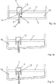
Figure 1 is a diagrammatic section view of part of a melting furnace according to the invention; -
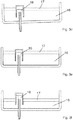
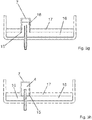
Figure 2 is an enlargement of some components of the furnace inFigure 1 ; - Figures from 3a to 3h diagrammatically represent some working sequences of the melting furnace according to the invention.
- The same reference numbers in the figures identify the same elements or components.
- The figures show a melting furnace for metallurgical plant according to the invention.
- The melting furnace is only partially shown in the figures and is represented as a whole by
reference numeral 1. Themelting furnace 1 is described only partially with particular reference to the elements which distinguish it from known furnaces. The parts of the furnace which are not described in detail herein should be understood as being in themselves known and conventional. - The
melting furnace 1 of the invention comprises in all its embodiments: - a vessel having a bottom 2 which is part of the floor of the furnace and which comprises an inner surface adapted to be in contact with the metal mass or metal bath contained in the
furnace 1; - a tapping
duct 3 passing through thebottom 2; - rotation means to rotate the vessel about a rotation axis X so that the tapping
duct 3 passes from a first reference position to a second position inclined with respect to said first reference position, and vice versa. - The rotation means comprise, for example, slides or rack mechanisms or shoes.
- The tapping
duct 3, preferably eccentric with respect to thebottom 2, has afirst stretch 6 arranged in the thickness of thebottom 2 and completely passing through the bottom itself, and asecond stretch 5, adjacent to thefirst stretch 6, protruding inside the vessel. Athird stretch 10 of the tappingduct 3 can be provided which protrudes outside the vessel, under the base floor of the furnace. Thestretches possible stretch 10 have the same longitudinal axis. - Advantageously, there is provided a
cover 7 of thesecond stretch 5 shaped as a bell, preferably a tube closed at anupper end 8 thereof and open at a lower end 9 thereof. Thecover 7 is a fixed cover, e.g. fixed to the walls of the vessel, coaxial and spaced from saidsecond stretch 5 and also spaced from a zone of the bottom 2 which includes thefirst stretch 6 of the tappingduct 3, whereby thecover 7, in cooperation with thesecond stretch 5 of the tappingduct 3, defines avolume 4 inside thecover 7 and adapted to act as a siphon. - Both the
cover 7 and the tappingduct 3 are made of refractory material or simply coated with a refractory material. - In the variant shown in
Figures 1-2 , having defined amaximum level 20 of the bath ofmolten metal material 16 inside the vessel, always comprised between the lower end 9 of thecover 7 and anupper edge 13 of thesecond stretch 5, saidsecond stretch 5 of the tappingduct 3 has a length H, measured starting from the part of bottom 2 from which it protrudes, so that theupper edge 13 of thesecond stretch 5 is always over saidmaximum level 20. - Advantageously, the length of the
second stretch 5 is greater than or equal to the thickness of the zone of the bottom 2 which includes thefirst stretch 6, preferably greater than or equal to the length of thefirst stretch 6. - Preferably, the length H of the
second stretch 5 of the tappingduct 3, measured starting from the part of bottom 2 from which it protrudes, is comprised between 800 and 1100 mm. - The length of the
first stretch 6 is preferably comprised between 600 and 850 mm. The length of the possiblethird stretch 10, for example, is comprised between 0 and 300 mm. - At least one burner can be provided at the outlet section of the
stretch 6 or of thestretch 10, adapted to be actuated at the end of tapping to clean the lower end of the tapping duct. - The tube defining the
cover 7 is defined by abase 11, placed at theupper end 8 thereof and spaced from anupper edge 13 of thesecond stretch 5 of the tappingduct 3, and by a cylindricallateral surface 12 arranged coaxially to the tappingduct 3 and spaced from theouter wall 14 of thesecond stretch 5. - Preferably, the distance A between the base 11 and the
upper edge 13 of thesecond stretch 5, the distance B between the cylindricallateral surface 12 and theouter wall 14 of thesecond stretch 5, and the distance C between alower edge 15 of the lower end 9 of thecover 7 and the zone of the bottom 2 which includes thefirst stretch 6, satisfy the following relationship: A=(B+C)*0,7. - Preferably, the distance A is comprised between 100 and 400 mm.
- Preferably, the distance B is comprised between 80 and 300 mm.
- Preferably, the distance C is comprised between 50 and 250 mm.
- The angular distance between the second position and the first position of the tapping
duct 3 is advantageously less than 10° so as to allow, even during the handling of the vessel and/or the tapping of the molten metal material, that further scrap can be charged into the vessel and that the melting can continue without interruption. - Preferably, said angular distance is comprised in the range between 3° and 8°, possibly including the limit values, still more preferably equal to 5°-6°, i.e. comprised in the range between 5° and 6° including the limit values.
- Alternatively, the
cover 7 can be a movable cover adapted to move along its own longitudinal axis. - An operating method of a melting furnace according to the invention, diagrammatically shown in Figures from 3a to 3h, is described below.
- Initially, the vessel is provided with the tapping
duct 3 in the first reference position, e.g. a vertical position, and there is provided a bath ofmolten metal material 16 at an equal level both inside and outside thecover 7 and comprised between thelower edge 15 of thecover 7 and anupper edge 13 of thesecond stretch 5, theslag 17 being kept on the surface of saidbath 16 outside the cover 7 (Figure 3a ). - Therefore, the method of the invention does not provide an initial level of the molten metal material bath higher than the
upper edge 13 of thesecond stretch 5 of the tapping duct, and therefore does not provide an initial tapping obtained exclusively by gravity. - The vessel is then rotated in a first direction of rotation (
Figures 3b and 3c ) so as to raise the molten metal material level in the vessel zone comprising the tappingduct 3, so that the tappingduct 3 passes from said first reference position to a second position inclined with respect to said first reference position, preferably by an angle lower than 10°, until the level of molten metal material reaches theupper edge 13 of thesecond stretch 5 so that the molten metal material begins to be tapped through the tappingduct 3 whereby creating a depression inside thevolume 4. - In particular,
Figure 3c shows a moment in which the level of the molten metal material inside thecover 7, i.e. inside thevolume 4, exceeds the level of theupper edge 13 of the tappingduct 3, whereby the molten material starts flowing through the tappingduct 3. - The depression produced inside the
cover 7, because of the beginning of the tapping, determines the passage of the molten metallic material from the outside of thecover 7 into thevolume 4 while the tapping continues, whereby causing a difference of level between the molten material inside thecover 7 and the molten material outside saidcover 7, the level becoming increasingly lower on the outside of the cover with respect to the inside. - The vessel is then rotated in a second direction of rotation (
Figures 3d, 3e, 3f ), opposite to the first direction of rotation, so that the tappingduct 3 returns in the first reference position (Figure 3f ) while the tapping of the molten metallic material continues. - Advantageously, it is possible to load and/or melt the scrap in the vessel also while tapping. Indeed,
Figures 3c to 3e , for example, show how the amount ofmolten metal material 16 increases inside the vessel. - The molten metal material continues to pass from the outside of the
cover 7 into thevolume 4 and continues to be tapped through the tappingduct 3 until the level of molten metal material outside thecover 7 reaches thelower edge 15 of the lower end 9 of the cover 7 (Figure 3g ). - At this point, with the passage of a minimum amount of air from the outside of the
cover 7 into thevolume 4, accompanied by a negligible amount ofslag 17, the depression inside thevolume 4 is canceled and the level ofmolten metal material 16 inside thecover 7 lowers quickly reaching thelower edge 15, and thus the same level of the molten metal material outside the cover 7 (Figure 3h ). - When the tapping ends (
Figure 3h ), and either scrap is loaded and/or melted in the vessel also during tapping or not, the method provides: - returning the bath of
molten metal material 16 to a level between thelower edge 15 of thecover 7 and theupper edge 13 of thesecond stretch 5 of the tapping duct (Figure 3a ); - repeating the steps illustrated in
Figures 3b to 3h . - Advantageously, the tapping
duct 3 is always kept open, even during the melting of the scrap inside the vessel, without needing to obstruct the tapping hole with sand and without needing to provide a closing valve. - A first alternative to the one described above, in order to cancel the depression inside the
volume 4 and interrupt the tapping, provides actuating the relief valve of the cover itself to equalize the pressure inside thecover 7 with that contained outside the cover, which generally corresponds to the atmospheric pressure present inside the vessel. A second alternative provides, instead, tilting the vessel with respect to the horizontal plane in direction opposite to the tilting direction activating the tapping, i.e. so as to raise the level of molten metal material in the vessel zone in which the tapping duct is not present. In this manner, the tappingduct 3 passes from said first reference position to a third position, inclined with respect to said first reference position, until the level of molten metal material inside thevolume 4 at least partially reaches thelower edge 15 of thecover 7, whereby allowing the passage of air inside the cover. - In these different manners, a perfect control on the amount of molten metal to be maintained inside the furnace (hot heel) is obtained for the successive melting.
Claims (15)
- An operating method of a melting furnace comprising- a vessel provided with a bottom (2);- a tapping duct (3) passing through the bottom (2) and having a first stretch (6) arranged in the thickness of the bottom (2) and completely passing through the bottom (2), and a second stretch (5), adjacent to the first stretch (6), protruding inside the vessel;- a fixed cover (7) of the second stretch (5) shaped as a bell, closed at an upper end (8) thereof and open at a lower end (9) thereof; said bell being coaxial and spaced from said second stretch (5), and being spaced from a zone of the bottom (2) which includes the first stretch (6) of the tapping duct (3), whereby the fixed cover (7), in cooperation with the second stretch (5) of the tapping duct (3), defines a volume (4) inside the fixed cover (7) and adapted to act as a tapping hood;- rotation means adapted to rotate the vessel so that the tapping duct (3) passes from a first reference position to a second position inclined with respect to said first reference position, and vice versa;the method comprising the following steps:a) providing the vessel with the tapping duct (3) in the first reference position and providing a bath of molten metal material (16) at an equal level both inside and outside the cover (7) and comprised between the lower end (9) of the cover (7) and an upper edge (13) of the second stretch (5), a slag (17) being kept on the surface of said bath outside the cover (7);b) rotating the vessel in a first direction so that the tapping duct (3) passes from said first reference position to said second position inclined until the level of molten metal material reaches the upper edge (13) of the second stretch (5) so that the molten metal material begins to be tapped through the tapping duct (3) creating a depression inside the volume (4);c) rotating the vessel in a second direction, opposite the first direction, so that the tapping duct (3) returns to the first reference position, while, due to said depression, the molten metal material passes from the outside of the cover (7) to the inside of the volume (4) and continues to be tapped through the tapping duct (3) until said depression is canceled.
- A method according to claim 1, wherein in step c) said depression is canceled when the level of molten metal material outside the fixed cover (7) reaches a lower edge (15) of the lower end (9) of the fixed cover (7), whereby, at the passage of air from the outside of the fixed cover (7) to the inside of the volume (4), the level of molten metal material inside the fixed cover (7) is lowered, reaching the lower edge (15), and therefore the same level of the molten metal material outside the fixed cover (7);
or wherein said depression is canceled by operating a relief valve provided on the fixed cover (7);
or wherein said depression is canceled by further rotating the vessel in said second direction, so that the tapping duct (3) passes from said first reference position to a third position inclined with respect to said first reference position until the level of molten metal material inside the volume (4) reaches the lower edge (15) of the fixed cover. - A method according to claim 1 or 2, wherein, following step c), with the tapping duct (3) in the first reference position, there are provided the steps of:- returning the bath of molten metal material to a level between the lower end (9) of the cover (7) and an upper edge (13) of the second stretch (5);- repeating steps b) and c).
- A method according to claim 1 or 2, wherein during at least steps b) and c) it is possible to load and/or melt scrap inside the vessel, also during the tapping.
- A method according to any one of the preceding claims, wherein the tapping duct (3) is always kept open, also during the melting of scrap inside the vessel.
- A melting furnace (1) for a metallurgical plant, adapted to carry out a method according to any one of the preceding claims, comprising:- a vessel provided with a bottom (2);- a tapping duct (3) passing through the bottom (2);wherein said tapping duct (3) has a first stretch (6) arranged in the thickness of the bottom (2) and completely passing through the bottom (2), and a second stretch (5), adjacent to the first stretch (6), protruding inside the vessel;
wherein there is provided a fixed cover (7) of the second stretch (5) shaped as a bell, closed at an upper end (8) thereof and open at a lower end (9) thereof; said bell being coaxial and spaced from said second stretch (5), and being spaced from a zone of the bottom (2) which includes the first stretch (6) of the tapping duct (3), whereby the fixed cover (7), in cooperation with the second stretch (5) of the tapping duct (3), defines a volume (4) inside the fixed cover (7) and adapted to act as a tapping hood; and wherein there are provided rotation means adapted to rotate the vessel in a first direction so that the tapping duct (3) passes from a first reference position to a second position inclined with respect to said first reference position, and then adapted to rotate the vessel in a second direction, opposite the first direction, so that the tapping duct (3) returns to the first reference position. - A melting furnace according to claim 6, wherein said second stretch (5) has a length greater than or equal to the thickness of a zone of the bottom (2) which includes the first stretch (6), preferably greater than or equal to the length of the first stretch (6).
- A melting furnace according to claim 6 or 7, wherein said bell is a tube defined by a base (11), placed at the upper end (8) thereof and spaced from an upper edge (13) of the second stretch (5) of the tapping duct (3), and by a cylindrical lateral surface (12) arranged coaxially to the tapping duct (3) and spaced from the outer wall (14) of the second stretch (5).
- A melting furnace according to any one of the claims from 6 to 8, wherein said fixed cover (7) is provided with a relief valve.
- A melting furnace according to any one of the claims from 6 to 9, wherein the angular distance between the second position and the first position is less than 10°.
- A melting furnace according to claim 8, wherein the distance (A) between the base (11) and the upper edge (13) of the second stretch (5), the distance (B) between the cylindrical lateral surface (12) and the outer wall (14) of the second stretch (5), and the distance (C) between a lower edge (15) of the lower end (9) of the fixed cover (7) and a zone of the bottom (2), which includes the first stretch (6), satisfies the following relationship: A=(B+C)*0,7.
- A melting furnace according to claim 8 or 11, wherein the distance (A) between the base (11) and the upper edge (13) of the second stretch (5) is comprised between 100 and 400 cm.
- A melting furnace according to claim 8 or 11 or 12, wherein the distance (B) between the cylindrical lateral surface (12) and the outer wall (14) of the second stretch (5) is comprised between 80 and 300 cm.
- A melting furnace according to claim 8 or 11 or 12 or 13, wherein the distance (C) between a lower edge (15) of the lower end (9) of the cover (7) and a zone of the bottom (2) which includes the first stretch (6) is comprised between 50 and 250 cm.
- A melting furnace according to any one of claims from 6 to 14, wherein, being defined a maximum level (20) of the bath of molten metal material (16) inside the vessel, comprised between a lower end (9) of the fixed cover (7) and an upper edge (13) of the second stretch (5), said second stretch (5) has a length H such that the upper edge (13) of the second stretch (5) is always over said maximum level (20).
Applications Claiming Priority (2)
| Application Number | Priority Date | Filing Date | Title |
|---|---|---|---|
| IT201700145098 | 2017-12-15 | ||
| PCT/IB2018/060090 WO2019116333A1 (en) | 2017-12-15 | 2018-12-14 | Melting furnace for metallurgical plant and operating method therefor |
Publications (2)
| Publication Number | Publication Date |
|---|---|
| EP3724586A1 EP3724586A1 (en) | 2020-10-21 |
| EP3724586B1 true EP3724586B1 (en) | 2021-09-01 |
Family
ID=61868688
Family Applications (1)
| Application Number | Title | Priority Date | Filing Date |
|---|---|---|---|
| EP18833324.9A Active EP3724586B1 (en) | 2017-12-15 | 2018-12-14 | Melting furnace for metallurgical plant and operating method therefor |
Country Status (6)
| Country | Link |
|---|---|
| US (1) | US11390927B2 (en) |
| EP (1) | EP3724586B1 (en) |
| CN (1) | CN111566429B (en) |
| ES (1) | ES2898960T3 (en) |
| RU (1) | RU2762438C1 (en) |
| WO (1) | WO2019116333A1 (en) |
Family Cites Families (12)
| Publication number | Priority date | Publication date | Assignee | Title |
|---|---|---|---|---|
| DE3412077A1 (en) * | 1984-03-31 | 1985-10-03 | Fried. Krupp Gmbh, 4300 Essen | TILTABLE METALLURGICAL OVEN CASE |
| DE3629055A1 (en) * | 1986-08-27 | 1988-03-03 | Kloeckner Cra Tech | METHOD FOR INCREASING ENERGY IN ELECTRIC ARC FURNACES |
| RU2086872C1 (en) * | 1993-01-25 | 1997-08-10 | Николай Иванович Русских | Method of tapping molten metal from metallurgical furnace and tap-hole for realization the same |
| CN1187566C (en) * | 1999-04-01 | 2005-02-02 | 艾克米特技术公司 | Metallurgical vessel comprising tapping device and method for controlled, slag-free extraction of mol ten metal from said vessel |
| US6473446B2 (en) * | 2000-12-13 | 2002-10-29 | Sms Demag, Inc. | Electric furnace for steel making |
| JP2006035238A (en) * | 2004-07-22 | 2006-02-09 | Hoei Shokai:Kk | Molten metal supply system, container and vehicle |
| RU2293937C2 (en) * | 2005-02-09 | 2007-02-20 | Техком Импорт Экспорт Гмбх | Metal melting vessel emptying method for discharging main part of melt metal through outlet opening in bottom surface of vessel and metal melting vessel |
| ITMI20050626A1 (en) * | 2005-04-13 | 2006-10-14 | Technit Compagnia Tecnica Inte | APPARATUS FOR MEASURING AND MONITORING THE FEEDING OF CHARGING OR SCRAPPING MATERIAL AT A OVEN AND ITS PROCEDURE |
| DE102005033287A1 (en) * | 2005-07-16 | 2007-01-25 | Sms Demag Ag | Melting furnace and method of operation |
| BE1019269A3 (en) * | 2010-04-02 | 2012-05-08 | Belgoprocess N V | TIPABLE OVEN. |
| US8562713B2 (en) * | 2011-05-27 | 2013-10-22 | A. Finkl & Sons Co. | Flexible minimum energy utilization electric arc furnace system and processes for making steel products |
| DE102013114811B3 (en) * | 2013-12-23 | 2014-12-31 | Ald Vacuum Technologies Gmbh | Apparatus and method for treating metallic material |
-
2018
- 2018-12-14 RU RU2020123485A patent/RU2762438C1/en active
- 2018-12-14 WO PCT/IB2018/060090 patent/WO2019116333A1/en not_active Ceased
- 2018-12-14 US US16/772,385 patent/US11390927B2/en active Active
- 2018-12-14 CN CN201880080155.7A patent/CN111566429B/en active Active
- 2018-12-14 EP EP18833324.9A patent/EP3724586B1/en active Active
- 2018-12-14 ES ES18833324T patent/ES2898960T3/en active Active
Also Published As
| Publication number | Publication date |
|---|---|
| CN111566429A (en) | 2020-08-21 |
| EP3724586A1 (en) | 2020-10-21 |
| CN111566429B (en) | 2022-05-27 |
| US20210079489A1 (en) | 2021-03-18 |
| US11390927B2 (en) | 2022-07-19 |
| ES2898960T3 (en) | 2022-03-09 |
| RU2762438C1 (en) | 2021-12-21 |
| WO2019116333A1 (en) | 2019-06-20 |
Similar Documents
| Publication | Publication Date | Title |
|---|---|---|
| US3472649A (en) | Electric-arc steelmaking | |
| RU2530578C2 (en) | Flexible electric arc furnace with minimum electric power consumption and method of steel products fabrication | |
| JP2002541422A (en) | Metallurgical vessel with tapping device and method for controlled removal of liquid metal from said vessel without slag | |
| US20090274190A1 (en) | Melting furnace, in particular electric arc furnace | |
| US5054033A (en) | Tiltable arc furnace | |
| US11390927B2 (en) | Melting furnace for metallurgical plant and operating method therefor | |
| US5462259A (en) | Tilting device for a D.C. arc furnace and process for emptying the furnace | |
| US5590151A (en) | Process for melting scrap iron in an electric furnace and installation for implementing the process | |
| US3898365A (en) | Electric arc furnace for melting and refining solid metal products | |
| KR102083534B1 (en) | Apparatus for treating molten metal And Method for slag skimming | |
| WO2015071823A1 (en) | Method for melting minerals containing iron, titanium and vanadium | |
| US4270949A (en) | Making of steel by the BOF process | |
| US4552343A (en) | Combination electric furnace and slag retaining pouring spout | |
| JP2020139180A (en) | Drainage method and molten metal manufacturing method in an arc-type electric furnace | |
| US4795139A (en) | Apparatus for tapping slag-free steel from a continuous melting furnace | |
| US4363653A (en) | Method and apparatus for melting solid pieces of metal | |
| US4563766A (en) | Electric arc furnace for melting metal, especially steel | |
| US682512A (en) | Open-hearth steel-furnace. | |
| US4488711A (en) | Treating ladle for ductile iron treatment | |
| CN112176149A (en) | Liquid metal refining device, liquid metal smelting system and refining method | |
| CN119683311B (en) | Ladle loading device and operation method thereof | |
| KR101510285B1 (en) | Apparatus for removing slag | |
| JPH0548070Y2 (en) | ||
| JPH0598337A (en) | Molten metal refining vessel and this operation method thereof | |
| US2379651A (en) | Electric resistor furnace for the heating and melting of metals |
Legal Events
| Date | Code | Title | Description |
|---|---|---|---|
| STAA | Information on the status of an ep patent application or granted ep patent |
Free format text: STATUS: UNKNOWN |
|
| STAA | Information on the status of an ep patent application or granted ep patent |
Free format text: STATUS: THE INTERNATIONAL PUBLICATION HAS BEEN MADE |
|
| PUAI | Public reference made under article 153(3) epc to a published international application that has entered the european phase |
Free format text: ORIGINAL CODE: 0009012 |
|
| STAA | Information on the status of an ep patent application or granted ep patent |
Free format text: STATUS: REQUEST FOR EXAMINATION WAS MADE |
|
| 17P | Request for examination filed |
Effective date: 20200710 |
|
| AK | Designated contracting states |
Kind code of ref document: A1 Designated state(s): AL AT BE BG CH CY CZ DE DK EE ES FI FR GB GR HR HU IE IS IT LI LT LU LV MC MK MT NL NO PL PT RO RS SE SI SK SM TR |
|
| AX | Request for extension of the european patent |
Extension state: BA ME |
|
| DAV | Request for validation of the european patent (deleted) | ||
| DAX | Request for extension of the european patent (deleted) | ||
| GRAP | Despatch of communication of intention to grant a patent |
Free format text: ORIGINAL CODE: EPIDOSNIGR1 |
|
| STAA | Information on the status of an ep patent application or granted ep patent |
Free format text: STATUS: GRANT OF PATENT IS INTENDED |
|
| RIC1 | Information provided on ipc code assigned before grant |
Ipc: C21C 5/52 20060101ALI20210311BHEP Ipc: C21C 5/46 20060101ALI20210311BHEP Ipc: F27D 3/15 20060101ALI20210311BHEP Ipc: F27B 3/19 20060101AFI20210311BHEP |
|
| INTG | Intention to grant announced |
Effective date: 20210325 |
|
| GRAS | Grant fee paid |
Free format text: ORIGINAL CODE: EPIDOSNIGR3 |
|
| GRAA | (expected) grant |
Free format text: ORIGINAL CODE: 0009210 |
|
| STAA | Information on the status of an ep patent application or granted ep patent |
Free format text: STATUS: THE PATENT HAS BEEN GRANTED |
|
| AK | Designated contracting states |
Kind code of ref document: B1 Designated state(s): AL AT BE BG CH CY CZ DE DK EE ES FI FR GB GR HR HU IE IS IT LI LT LU LV MC MK MT NL NO PL PT RO RS SE SI SK SM TR |
|
| REG | Reference to a national code |
Ref country code: GB Ref legal event code: FG4D |
|
| REG | Reference to a national code |
Ref country code: CH Ref legal event code: EP Ref country code: AT Ref legal event code: REF Ref document number: 1426649 Country of ref document: AT Kind code of ref document: T Effective date: 20210915 |
|
| REG | Reference to a national code |
Ref country code: DE Ref legal event code: R096 Ref document number: 602018023048 Country of ref document: DE |
|
| REG | Reference to a national code |
Ref country code: IE Ref legal event code: FG4D |
|
| REG | Reference to a national code |
Ref country code: LT Ref legal event code: MG9D |
|
| REG | Reference to a national code |
Ref country code: NL Ref legal event code: MP Effective date: 20210901 |
|
| PG25 | Lapsed in a contracting state [announced via postgrant information from national office to epo] |
Ref country code: SE Free format text: LAPSE BECAUSE OF FAILURE TO SUBMIT A TRANSLATION OF THE DESCRIPTION OR TO PAY THE FEE WITHIN THE PRESCRIBED TIME-LIMIT Effective date: 20210901 Ref country code: RS Free format text: LAPSE BECAUSE OF FAILURE TO SUBMIT A TRANSLATION OF THE DESCRIPTION OR TO PAY THE FEE WITHIN THE PRESCRIBED TIME-LIMIT Effective date: 20210901 Ref country code: FI Free format text: LAPSE BECAUSE OF FAILURE TO SUBMIT A TRANSLATION OF THE DESCRIPTION OR TO PAY THE FEE WITHIN THE PRESCRIBED TIME-LIMIT Effective date: 20210901 Ref country code: NO Free format text: LAPSE BECAUSE OF FAILURE TO SUBMIT A TRANSLATION OF THE DESCRIPTION OR TO PAY THE FEE WITHIN THE PRESCRIBED TIME-LIMIT Effective date: 20211201 Ref country code: HR Free format text: LAPSE BECAUSE OF FAILURE TO SUBMIT A TRANSLATION OF THE DESCRIPTION OR TO PAY THE FEE WITHIN THE PRESCRIBED TIME-LIMIT Effective date: 20210901 Ref country code: BG Free format text: LAPSE BECAUSE OF FAILURE TO SUBMIT A TRANSLATION OF THE DESCRIPTION OR TO PAY THE FEE WITHIN THE PRESCRIBED TIME-LIMIT Effective date: 20211201 Ref country code: LT Free format text: LAPSE BECAUSE OF FAILURE TO SUBMIT A TRANSLATION OF THE DESCRIPTION OR TO PAY THE FEE WITHIN THE PRESCRIBED TIME-LIMIT Effective date: 20210901 |
|
| PG25 | Lapsed in a contracting state [announced via postgrant information from national office to epo] |
Ref country code: PL Free format text: LAPSE BECAUSE OF FAILURE TO SUBMIT A TRANSLATION OF THE DESCRIPTION OR TO PAY THE FEE WITHIN THE PRESCRIBED TIME-LIMIT Effective date: 20210901 Ref country code: LV Free format text: LAPSE BECAUSE OF FAILURE TO SUBMIT A TRANSLATION OF THE DESCRIPTION OR TO PAY THE FEE WITHIN THE PRESCRIBED TIME-LIMIT Effective date: 20210901 Ref country code: GR Free format text: LAPSE BECAUSE OF FAILURE TO SUBMIT A TRANSLATION OF THE DESCRIPTION OR TO PAY THE FEE WITHIN THE PRESCRIBED TIME-LIMIT Effective date: 20211202 |
|
| REG | Reference to a national code |
Ref country code: ES Ref legal event code: FG2A Ref document number: 2898960 Country of ref document: ES Kind code of ref document: T3 Effective date: 20220309 |
|
| PG25 | Lapsed in a contracting state [announced via postgrant information from national office to epo] |
Ref country code: IS Free format text: LAPSE BECAUSE OF FAILURE TO SUBMIT A TRANSLATION OF THE DESCRIPTION OR TO PAY THE FEE WITHIN THE PRESCRIBED TIME-LIMIT Effective date: 20220101 Ref country code: SM Free format text: LAPSE BECAUSE OF FAILURE TO SUBMIT A TRANSLATION OF THE DESCRIPTION OR TO PAY THE FEE WITHIN THE PRESCRIBED TIME-LIMIT Effective date: 20210901 Ref country code: SK Free format text: LAPSE BECAUSE OF FAILURE TO SUBMIT A TRANSLATION OF THE DESCRIPTION OR TO PAY THE FEE WITHIN THE PRESCRIBED TIME-LIMIT Effective date: 20210901 Ref country code: RO Free format text: LAPSE BECAUSE OF FAILURE TO SUBMIT A TRANSLATION OF THE DESCRIPTION OR TO PAY THE FEE WITHIN THE PRESCRIBED TIME-LIMIT Effective date: 20210901 Ref country code: PT Free format text: LAPSE BECAUSE OF FAILURE TO SUBMIT A TRANSLATION OF THE DESCRIPTION OR TO PAY THE FEE WITHIN THE PRESCRIBED TIME-LIMIT Effective date: 20220103 Ref country code: NL Free format text: LAPSE BECAUSE OF FAILURE TO SUBMIT A TRANSLATION OF THE DESCRIPTION OR TO PAY THE FEE WITHIN THE PRESCRIBED TIME-LIMIT Effective date: 20210901 Ref country code: EE Free format text: LAPSE BECAUSE OF FAILURE TO SUBMIT A TRANSLATION OF THE DESCRIPTION OR TO PAY THE FEE WITHIN THE PRESCRIBED TIME-LIMIT Effective date: 20210901 Ref country code: CZ Free format text: LAPSE BECAUSE OF FAILURE TO SUBMIT A TRANSLATION OF THE DESCRIPTION OR TO PAY THE FEE WITHIN THE PRESCRIBED TIME-LIMIT Effective date: 20210901 Ref country code: AL Free format text: LAPSE BECAUSE OF FAILURE TO SUBMIT A TRANSLATION OF THE DESCRIPTION OR TO PAY THE FEE WITHIN THE PRESCRIBED TIME-LIMIT Effective date: 20210901 |
|
| REG | Reference to a national code |
Ref country code: DE Ref legal event code: R097 Ref document number: 602018023048 Country of ref document: DE |
|
| PLBE | No opposition filed within time limit |
Free format text: ORIGINAL CODE: 0009261 |
|
| STAA | Information on the status of an ep patent application or granted ep patent |
Free format text: STATUS: NO OPPOSITION FILED WITHIN TIME LIMIT |
|
| PG25 | Lapsed in a contracting state [announced via postgrant information from national office to epo] |
Ref country code: MC Free format text: LAPSE BECAUSE OF FAILURE TO SUBMIT A TRANSLATION OF THE DESCRIPTION OR TO PAY THE FEE WITHIN THE PRESCRIBED TIME-LIMIT Effective date: 20210901 Ref country code: DK Free format text: LAPSE BECAUSE OF FAILURE TO SUBMIT A TRANSLATION OF THE DESCRIPTION OR TO PAY THE FEE WITHIN THE PRESCRIBED TIME-LIMIT Effective date: 20210901 |
|
| 26N | No opposition filed |
Effective date: 20220602 |
|
| PG25 | Lapsed in a contracting state [announced via postgrant information from national office to epo] |
Ref country code: SI Free format text: LAPSE BECAUSE OF FAILURE TO SUBMIT A TRANSLATION OF THE DESCRIPTION OR TO PAY THE FEE WITHIN THE PRESCRIBED TIME-LIMIT Effective date: 20210901 |
|
| REG | Reference to a national code |
Ref country code: BE Ref legal event code: MM Effective date: 20211231 |
|
| PG25 | Lapsed in a contracting state [announced via postgrant information from national office to epo] |
Ref country code: LU Free format text: LAPSE BECAUSE OF NON-PAYMENT OF DUE FEES Effective date: 20211214 Ref country code: IE Free format text: LAPSE BECAUSE OF NON-PAYMENT OF DUE FEES Effective date: 20211214 |
|
| PG25 | Lapsed in a contracting state [announced via postgrant information from national office to epo] |
Ref country code: FR Free format text: LAPSE BECAUSE OF NON-PAYMENT OF DUE FEES Effective date: 20211231 Ref country code: BE Free format text: LAPSE BECAUSE OF NON-PAYMENT OF DUE FEES Effective date: 20211231 |
|
| P01 | Opt-out of the competence of the unified patent court (upc) registered |
Effective date: 20230511 |
|
| PG25 | Lapsed in a contracting state [announced via postgrant information from national office to epo] |
Ref country code: CY Free format text: LAPSE BECAUSE OF FAILURE TO SUBMIT A TRANSLATION OF THE DESCRIPTION OR TO PAY THE FEE WITHIN THE PRESCRIBED TIME-LIMIT Effective date: 20210901 |
|
| PG25 | Lapsed in a contracting state [announced via postgrant information from national office to epo] |
Ref country code: HU Free format text: LAPSE BECAUSE OF FAILURE TO SUBMIT A TRANSLATION OF THE DESCRIPTION OR TO PAY THE FEE WITHIN THE PRESCRIBED TIME-LIMIT; INVALID AB INITIO Effective date: 20181214 |
|
| GBPC | Gb: european patent ceased through non-payment of renewal fee |
Effective date: 20221214 |
|
| PG25 | Lapsed in a contracting state [announced via postgrant information from national office to epo] |
Ref country code: GB Free format text: LAPSE BECAUSE OF NON-PAYMENT OF DUE FEES Effective date: 20221214 |
|
| REG | Reference to a national code |
Ref country code: AT Ref legal event code: UEP Ref document number: 1426649 Country of ref document: AT Kind code of ref document: T Effective date: 20210901 |
|
| PG25 | Lapsed in a contracting state [announced via postgrant information from national office to epo] |
Ref country code: MK Free format text: LAPSE BECAUSE OF FAILURE TO SUBMIT A TRANSLATION OF THE DESCRIPTION OR TO PAY THE FEE WITHIN THE PRESCRIBED TIME-LIMIT Effective date: 20210901 |
|
| PG25 | Lapsed in a contracting state [announced via postgrant information from national office to epo] |
Ref country code: MT Free format text: LAPSE BECAUSE OF FAILURE TO SUBMIT A TRANSLATION OF THE DESCRIPTION OR TO PAY THE FEE WITHIN THE PRESCRIBED TIME-LIMIT Effective date: 20210901 |
|
| REG | Reference to a national code |
Ref country code: CH Ref legal event code: U11 Free format text: ST27 STATUS EVENT CODE: U-0-0-U10-U11 (AS PROVIDED BY THE NATIONAL OFFICE) Effective date: 20260101 |
|
| PGFP | Annual fee paid to national office [announced via postgrant information from national office to epo] |
Ref country code: AT Payment date: 20251230 Year of fee payment: 8 |
|
| PGFP | Annual fee paid to national office [announced via postgrant information from national office to epo] |
Ref country code: IT Payment date: 20251219 Year of fee payment: 8 |
|
| PGFP | Annual fee paid to national office [announced via postgrant information from national office to epo] |
Ref country code: TR Payment date: 20251121 Year of fee payment: 8 |
|
| PGFP | Annual fee paid to national office [announced via postgrant information from national office to epo] |
Ref country code: ES Payment date: 20260102 Year of fee payment: 8 |
|
| PGFP | Annual fee paid to national office [announced via postgrant information from national office to epo] |
Ref country code: DE Payment date: 20251229 Year of fee payment: 8 |
|
| PGFP | Annual fee paid to national office [announced via postgrant information from national office to epo] |
Ref country code: CH Payment date: 20260101 Year of fee payment: 8 |