EP3724547B1 - Screen mounting system - Google Patents
Screen mounting system Download PDFInfo
- Publication number
- EP3724547B1 EP3724547B1 EP18888502.4A EP18888502A EP3724547B1 EP 3724547 B1 EP3724547 B1 EP 3724547B1 EP 18888502 A EP18888502 A EP 18888502A EP 3724547 B1 EP3724547 B1 EP 3724547B1
- Authority
- EP
- European Patent Office
- Prior art keywords
- mounting
- spaced
- brackets
- wall
- apart brackets
- Prior art date
- Legal status (The legal status is an assumption and is not a legal conclusion. Google has not performed a legal analysis and makes no representation as to the accuracy of the status listed.)
- Active
Links
Images










Classifications
-
- F—MECHANICAL ENGINEERING; LIGHTING; HEATING; WEAPONS; BLASTING
- F16—ENGINEERING ELEMENTS AND UNITS; GENERAL MEASURES FOR PRODUCING AND MAINTAINING EFFECTIVE FUNCTIONING OF MACHINES OR INSTALLATIONS; THERMAL INSULATION IN GENERAL
- F16M—FRAMES, CASINGS OR BEDS OF ENGINES, MACHINES OR APPARATUS, NOT SPECIFIC TO ENGINES, MACHINES OR APPARATUS PROVIDED FOR ELSEWHERE; STANDS; SUPPORTS
- F16M11/00—Stands or trestles as supports for apparatus or articles placed thereon ; Stands for scientific apparatus such as gravitational force meters
- F16M11/20—Undercarriages with or without wheels
- F16M11/2085—Undercarriages with or without wheels comprising means allowing sideward adjustment, i.e. left-right translation of the head relatively to the undercarriage
-
- H—ELECTRICITY
- H04—ELECTRIC COMMUNICATION TECHNIQUE
- H04N—PICTORIAL COMMUNICATION, e.g. TELEVISION
- H04N5/00—Details of television systems
- H04N5/64—Constructional details of receivers, e.g. cabinets or dust covers
- H04N5/655—Construction or mounting of chassis, e.g. for varying the elevation of the tube
-
- A—HUMAN NECESSITIES
- A47—FURNITURE; DOMESTIC ARTICLES OR APPLIANCES; COFFEE MILLS; SPICE MILLS; SUCTION CLEANERS IN GENERAL
- A47B—TABLES; DESKS; OFFICE FURNITURE; CABINETS; DRAWERS; GENERAL DETAILS OF FURNITURE
- A47B97/00—Furniture or accessories for furniture, not provided for in other groups of this subclass
- A47B97/001—Wall mounting or suspension arrangements for blackboards or the like
-
- F—MECHANICAL ENGINEERING; LIGHTING; HEATING; WEAPONS; BLASTING
- F16—ENGINEERING ELEMENTS AND UNITS; GENERAL MEASURES FOR PRODUCING AND MAINTAINING EFFECTIVE FUNCTIONING OF MACHINES OR INSTALLATIONS; THERMAL INSULATION IN GENERAL
- F16M—FRAMES, CASINGS OR BEDS OF ENGINES, MACHINES OR APPARATUS, NOT SPECIFIC TO ENGINES, MACHINES OR APPARATUS PROVIDED FOR ELSEWHERE; STANDS; SUPPORTS
- F16M11/00—Stands or trestles as supports for apparatus or articles placed thereon ; Stands for scientific apparatus such as gravitational force meters
- F16M11/02—Heads
- F16M11/04—Means for attachment of apparatus; Means allowing adjustment of the apparatus relatively to the stand
- F16M11/041—Allowing quick release of the apparatus
-
- F—MECHANICAL ENGINEERING; LIGHTING; HEATING; WEAPONS; BLASTING
- F16—ENGINEERING ELEMENTS AND UNITS; GENERAL MEASURES FOR PRODUCING AND MAINTAINING EFFECTIVE FUNCTIONING OF MACHINES OR INSTALLATIONS; THERMAL INSULATION IN GENERAL
- F16M—FRAMES, CASINGS OR BEDS OF ENGINES, MACHINES OR APPARATUS, NOT SPECIFIC TO ENGINES, MACHINES OR APPARATUS PROVIDED FOR ELSEWHERE; STANDS; SUPPORTS
- F16M11/00—Stands or trestles as supports for apparatus or articles placed thereon ; Stands for scientific apparatus such as gravitational force meters
- F16M11/02—Heads
- F16M11/04—Means for attachment of apparatus; Means allowing adjustment of the apparatus relatively to the stand
- F16M11/043—Allowing translations
- F16M11/048—Allowing translations adapted to forward-backward translation movement
-
- F—MECHANICAL ENGINEERING; LIGHTING; HEATING; WEAPONS; BLASTING
- F16—ENGINEERING ELEMENTS AND UNITS; GENERAL MEASURES FOR PRODUCING AND MAINTAINING EFFECTIVE FUNCTIONING OF MACHINES OR INSTALLATIONS; THERMAL INSULATION IN GENERAL
- F16M—FRAMES, CASINGS OR BEDS OF ENGINES, MACHINES OR APPARATUS, NOT SPECIFIC TO ENGINES, MACHINES OR APPARATUS PROVIDED FOR ELSEWHERE; STANDS; SUPPORTS
- F16M11/00—Stands or trestles as supports for apparatus or articles placed thereon ; Stands for scientific apparatus such as gravitational force meters
- F16M11/02—Heads
- F16M11/04—Means for attachment of apparatus; Means allowing adjustment of the apparatus relatively to the stand
- F16M11/06—Means for attachment of apparatus; Means allowing adjustment of the apparatus relatively to the stand allowing pivoting
-
- F—MECHANICAL ENGINEERING; LIGHTING; HEATING; WEAPONS; BLASTING
- F16—ENGINEERING ELEMENTS AND UNITS; GENERAL MEASURES FOR PRODUCING AND MAINTAINING EFFECTIVE FUNCTIONING OF MACHINES OR INSTALLATIONS; THERMAL INSULATION IN GENERAL
- F16M—FRAMES, CASINGS OR BEDS OF ENGINES, MACHINES OR APPARATUS, NOT SPECIFIC TO ENGINES, MACHINES OR APPARATUS PROVIDED FOR ELSEWHERE; STANDS; SUPPORTS
- F16M11/00—Stands or trestles as supports for apparatus or articles placed thereon ; Stands for scientific apparatus such as gravitational force meters
- F16M11/02—Heads
- F16M11/04—Means for attachment of apparatus; Means allowing adjustment of the apparatus relatively to the stand
- F16M11/06—Means for attachment of apparatus; Means allowing adjustment of the apparatus relatively to the stand allowing pivoting
- F16M11/10—Means for attachment of apparatus; Means allowing adjustment of the apparatus relatively to the stand allowing pivoting around a horizontal axis
-
- F—MECHANICAL ENGINEERING; LIGHTING; HEATING; WEAPONS; BLASTING
- F16—ENGINEERING ELEMENTS AND UNITS; GENERAL MEASURES FOR PRODUCING AND MAINTAINING EFFECTIVE FUNCTIONING OF MACHINES OR INSTALLATIONS; THERMAL INSULATION IN GENERAL
- F16M—FRAMES, CASINGS OR BEDS OF ENGINES, MACHINES OR APPARATUS, NOT SPECIFIC TO ENGINES, MACHINES OR APPARATUS PROVIDED FOR ELSEWHERE; STANDS; SUPPORTS
- F16M11/00—Stands or trestles as supports for apparatus or articles placed thereon ; Stands for scientific apparatus such as gravitational force meters
- F16M11/02—Heads
- F16M11/04—Means for attachment of apparatus; Means allowing adjustment of the apparatus relatively to the stand
- F16M11/06—Means for attachment of apparatus; Means allowing adjustment of the apparatus relatively to the stand allowing pivoting
- F16M11/12—Means for attachment of apparatus; Means allowing adjustment of the apparatus relatively to the stand allowing pivoting in more than one direction
- F16M11/121—Means for attachment of apparatus; Means allowing adjustment of the apparatus relatively to the stand allowing pivoting in more than one direction constituted of several dependent joints
-
- F—MECHANICAL ENGINEERING; LIGHTING; HEATING; WEAPONS; BLASTING
- F16—ENGINEERING ELEMENTS AND UNITS; GENERAL MEASURES FOR PRODUCING AND MAINTAINING EFFECTIVE FUNCTIONING OF MACHINES OR INSTALLATIONS; THERMAL INSULATION IN GENERAL
- F16M—FRAMES, CASINGS OR BEDS OF ENGINES, MACHINES OR APPARATUS, NOT SPECIFIC TO ENGINES, MACHINES OR APPARATUS PROVIDED FOR ELSEWHERE; STANDS; SUPPORTS
- F16M13/00—Other supports for positioning apparatus or articles; Means for steadying hand-held apparatus or articles
- F16M13/02—Other supports for positioning apparatus or articles; Means for steadying hand-held apparatus or articles for supporting on, or attaching to, an object, e.g. tree, gate, window-frame, cycle
- F16M13/022—Other supports for positioning apparatus or articles; Means for steadying hand-held apparatus or articles for supporting on, or attaching to, an object, e.g. tree, gate, window-frame, cycle repositionable
-
- G—PHYSICS
- G09—EDUCATION; CRYPTOGRAPHY; DISPLAY; ADVERTISING; SEALS
- G09F—DISPLAYING; ADVERTISING; SIGNS; LABELS OR NAME-PLATES; SEALS
- G09F9/00—Indicating arrangements for variable information in which the information is built-up on a support by selection or combination of individual elements
- G09F9/30—Indicating arrangements for variable information in which the information is built-up on a support by selection or combination of individual elements in which the desired character or characters are formed by combining individual elements
- G09F9/302—Indicating arrangements for variable information in which the information is built-up on a support by selection or combination of individual elements in which the desired character or characters are formed by combining individual elements characterised by the form or geometrical disposition of the individual elements
- G09F9/3026—Video wall, i.e. stackable semiconductor matrix display modules
-
- H—ELECTRICITY
- H04—ELECTRIC COMMUNICATION TECHNIQUE
- H04N—PICTORIAL COMMUNICATION, e.g. TELEVISION
- H04N5/00—Details of television systems
- H04N5/64—Constructional details of receivers, e.g. cabinets or dust covers
-
- Y—GENERAL TAGGING OF NEW TECHNOLOGICAL DEVELOPMENTS; GENERAL TAGGING OF CROSS-SECTIONAL TECHNOLOGIES SPANNING OVER SEVERAL SECTIONS OF THE IPC; TECHNICAL SUBJECTS COVERED BY FORMER USPC CROSS-REFERENCE ART COLLECTIONS [XRACs] AND DIGESTS
- Y10—TECHNICAL SUBJECTS COVERED BY FORMER USPC
- Y10S—TECHNICAL SUBJECTS COVERED BY FORMER USPC CROSS-REFERENCE ART COLLECTIONS [XRACs] AND DIGESTS
- Y10S248/00—Supports
- Y10S248/917—Video display screen support
Definitions
- the present invention relates to mounting systems for televisions and monitors, and in particular to mounting systems for an array of televisions and monitors.
- LED, LCD or other flat panel display type televisions or monitors electronic display devices
- mounts can be difficult and cumbersome to assemble. These mounts sometimes do not offer adjustibilty to account for external factors such as walls that are not entirely flat, leading to an unattractive installation. Also, the mounts are not easily scalable, so that different models must be offered depending on the size of the array of electronic displays desired.
- document WO 2017 / 044622 A1 relates to adjustable mounting systems for mounting flat- panel displays and similar devices.
- Document KR 101 695 929 B1 is directed at a wall mount for multi-display.
- Document US 2013 / 048812 A1 relates to a flat panel television or video display mounting system.
- the present invention is defined by the independent claim and provides a mounting solution for arrays of electronic display devices that addresses the drawbacks of prior mounts.
- scalably sized modular mounting frames can be easily assembled and linked together to form a mounting system that can accommodate multiple vertically and horizontally adjacent electronic displays.
- the system can have adjustable mounting legs enabling correction for walls, to which the system will be mounted, that are not entirely flat and also enabling positioning of the overall system within a range of adjustment closer or further away from the wall.
- the modular configuration of the mounting system can provide for vertical attachment of multiple electronic displays to a single module, and for vertical and horizontal attachment of multiple modules.
- the disclosed modular system enables multiple displays to be mounted in a virtually unlimited number of shapes as well as the standard square and rectangular arrays.
- Elongated attachment slots enable an electronic display to be moved laterally while adjacent electronic displays are being installed so that the electronic displays do not necessarily contact each other during initial installation so as to prevent damage to the individual electronic displays.
- the elongated attachment slots also enable horizontal adjustment of the electronic displays to compensate for tolerance buildups so as to ensure the displays can be slid together tightly in the horizontal (lateral) direction during final installation.
- a pusher mechanism can be included that will push against the display fasteners during installation so as to enable the electronic display devices to be pushed tightly together and inhibit unauthorized removal.
- slots can placed at key-points on the mount to enable a tape measure to be used during installation, thereby easing measurements during installation.
- a system for mounting multiple electronic display devices to a wall of a structure includes a first pair of spaced-apart brackets, each bracket presenting a front flange defining a plurality of slots, each slot adapted to receive a fastener coupled to an electronic display so as to attach the electronic display to the bracket, and a plurality of mounting feet operably coupled to each of the spaced-apart brackets, each of the mounting feet adapted to attach to the wall and defining a slot enabling the mounting foot to shift parallel to a plane of the wall, each of the plurality of mounting feet being separately shiftable relative to the spaced-apart brackets so as to enable the bracket to be selectively adjusted for position in a direction perpendicular to the wall.
- each of the plurality of mounting feet is shiftable relative to the spaced-apart brackets with an adjustment screw assembly.
- the slots defined in each mounting foot can be teardrop shaped, and the slots defined in the spaced-apart brackets can be teardrop shaped.
- the system can further include a second pair of spaced-apart brackets, each of the second pair of brackets presenting a front flange defining a plurality of slots, each slot adapted to receive a fastener coupled to an electronic display so as to attach the electronic display to the second pair of spaced-apart brackets and a plurality of mounting feet operably coupled to each of the second pair of spaced-apart brackets, each of the mounting feet adapted to attach to the wall and defining a slot enabling the mounting foot to shift parallel to a plane of the wall, each of the plurality of mounting feet being separately shiftable relative to the spaced-apart brackets so as to enable the bracket to be selectively adjusted for position in a direction perpendicular to the wall, the second pair of spaced-apart apart brackets operably coupled to the first pair of spaced-apart brackets in a horizontally or vertically adjacent relation.
- the first or the second pair of spaced-apart brackets can receive one, two, three, or four electronic displays, and can be coupled together vertically or horizontally to form arrays of electronic displays of various shapes.
- a mount 20 for a single (1 x 1) electronic display device depicted in FIG. 1a and 8 generally includes brackets 22, 23, cross-braces 24, and mounting foot assemblies 26. Brackets 22, 23, define teardrop slots 28 in front facing flanges 30. Side facing flanges 32 of brackets 22, 23, define apertures receiving fasteners 34, and keyhole slots 36. Cross-braces 24 are secured to each of brackets 23, 23, with fasteners 38, and hold brackets 22, 23, in a parallel, spaced apart relation.
- mounting foot assemblies 26 generally include mounting bracket 40 defining keyhole slot 42 on lateral flange 44, and adjustment slots 46 on perpendicular flange 48.
- Adjustment block 50 is rigidly attached to mounting bracket 40 with fasteners 52, and receives adjustment screw assembly 54.
- Mounting foot assemblies 26 are adjustably coupled to brackets 22, 23, with adjustment screw assembly 54, and with fasteners 34 slidably received in adjustment slots 46 such that turning adjustment screw assembly 54 causes lateral flange 44 to be moved closer or further away from front facing flanges 30, depending on the direction of rotation of adjustment screw 54.
- mount 20 can be attached to a wall with fasteners (not depicted) through keyhole slots 42.
- the head of fastener already projecting from the wall can be advanced through round portion 56 of slot 42 and then mount 20 moved downward so that the fastener moves through neck portion 58 and into lateral slot portion 60.
- mount 20 can be slid horizontally, guided by lateral slot portion 60 so that mount 20 can be adjusted for lateral position on the wall.
- the position of front facing flanges 30 can be adjusted relative to the wall by turning adjustment screw 54.
- the front facing flanges 30 can be adjusted to enable an attached screen to be adjusted in roll and pitch relative to the wall and other displays mounted adjacent.
- Screen 62 is attached to mount 20 with-fastening buttons 64.
- Each fastening button 64 has head portion 66 and neck portion 68. Head portion 66 is advanced through rounded portion 70 of teardrop slot 28, and screen 62 moved downward so that neck portion 68 moves through narrow portion 72 and into lateral slot 74. From there, screen 62 can be slid laterally with neck portion 68 guided in lateral slot 74.
- the position of fastening button 64 in teardrop slot 28 can be adjusted and secured with pusher screw 76 received in apertures provided in brackets 22, 23, and using stop block 78 as depicted in FIG.3 .
- Brackets 22, 23, can be made an extended length with teardrop slots 28 located at appropriate positions on front facing flanges 30 so as to enable two, three, or more displays to be mounted in a vertical array.
- multiple mounts 20 can be positioned vertically with fasteners in vertical slots 80 to link the mounts together vertically as depicted in FIG. 4b .
- mounts 20 can be linked horizontally as depicted in FIGs. 4a , 6a , 6b , and 7a , with fasteners 82 through keyhole slots 36 and received in link bars 84. In this way, virtually unlimited configurations of horizontal and vertical arrays of screens can be achieved.
- a mount 120 for two electronic display devices generally includes brackets 122, 123, cross-braces 124, and mounting foot assemblies 126.
- Brackets 122, 123 define teardrop slots 128 in front facing flanges 130.
- Side facing flanges 132 of brackets 122, 123 define apertures receiving fasteners 134, and keyhole slots 36.
- Cross-braces 124 are secured to each of brackets 123, 123, with fasteners 138, and hold brackets 122, 123, in a parallel, spaced apart relation.
- mounting foot assemblies 126 generally include mounting bracket 140, and attachment portion 141, with mounting bracket 140 defining teardrop slot 142 on lateral flange 144. Attachment portion 141 is secured to mounting bracket 140 with fasteners 143. Adjustment slots 146 are defined in perpendicular flanges 148 of attachment portion 141. Adjustment block 150 is rigidly attached to mounting bracket 140 with fasteners 152, and receives adjustment screw assembly 154 with adjustment nut 155 threaded on adjustment screw 157.
- Mounting foot assemblies 126 are adjustably coupled to brackets 122, 123, through adjustment screw 154, and with fasteners 134 slidably received in adjustment slots 146 such that turning adjustment nut 155 on adjustment screw 154 causes lateral flange 144 to be moved closer or further away from front facing flanges 130, depending on the direction of rotation of adjustment nut 155.
- mount 120 can be attached to a wall with fasteners (not depicted) through teardrop slots 142.
- the head of such a fastener already projecting from the wall can be advanced through lower portion 156 of slot 42 and then mount 120 moved downward so that the fastener moves through neck portion 158 and into lateral slot portion 160.
- mount 120 can be slid horizontally, guided by lateral slot portion 160 so that mount 120 can be adjusted for lateral position on the wall.
- the position of front facing flanges 130 can be adjusted inwardly and outwardly relative to the wall by turning adjustment nut 155.
- the front facing flanges 130 can be adjusted to enable an attached electronic display to be adjusted in roll and pitch relative to the wall and other displays 62 mounted adjacent.
- each fastening button 64 has head portion 66 and neck portion 68 as depicted in FIG. 5a .
- Each head portion 66 is advanced through rounded portion 170 of teardrop slots 128, and screen 62 moved downward so that neck portion 68 moves through narrow portion 172 and into lateral slot 174. From there, screen 62 can be slid laterally with neck portion 68 guided in lateral slot 174.
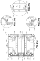
- the position of fastening button 64 in teardrop slot 128 can be adjusted and secured with pusher screw 176 received in apertures provided in side facing flanges 132 of brackets 122 or 123 as depicted in Fig. 21a - 21d .
- a stop fastener 179 can be threaded in to limit lateral travel to a predetermined range as depicted in FIGs. 26a and 26b .
- Brackets 122, 123 can be made an extended length with teardrop slots 128 located at appropriate positions on front facing flanges 130 so as to enable two, three, four, or more displays to be mounted in a vertical array.
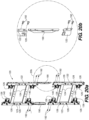
- multiple mounts 120 can be connected vertically with brackets 190 secured with fasteners 192 as depicted in FIGs. 20a and 20b .
- mounts 20 can be linked horizontally with brackets 194 as depicted in FIG. 19 .
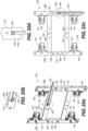
- brackets 194 As such, a virtually unlimited variety of overall array shapes of electronic displays can be achieved, with non-limiting exemplary embodiments depicted in FIGs, 17a, 17b , 18a, 18b , 23a, 23b , 24a, and 24b .
- slots 200 can be provided in brackets 122, 123, and/or cross-braces 124 to receive the perpendicular end 202 of a common tape measure 204, as depicted in FIGs. 22a - 22d .
- Slots 200 can be located at the approximate mid-point of attached electronic displays 62 to enable easy measurement relative to a floor, ceiling, or adjacent walls of a structure and thereby enable precise positioning of the electronic displays.
- side panels 206 can be attached to system 120 with brackets 208 to provide for a finished appearance to the installation.
Landscapes
- Engineering & Computer Science (AREA)
- General Engineering & Computer Science (AREA)
- Mechanical Engineering (AREA)
- Multimedia (AREA)
- Signal Processing (AREA)
- Physics & Mathematics (AREA)
- General Physics & Mathematics (AREA)
- Theoretical Computer Science (AREA)
- Devices For Indicating Variable Information By Combining Individual Elements (AREA)
- Casings For Electric Apparatus (AREA)
Description
- The present invention relates to mounting systems for televisions and monitors, and in particular to mounting systems for an array of televisions and monitors.
- It is increasingly common in public spaces to mount LED, LCD or other flat panel display type televisions or monitors (electronic display devices) to form an overall display that can be easily changed for the purpose of presenting information, advertising, or entertainment. Often, several of these devices are mounted adjacent to form an overall display larger than can be done with a single electronic display.
- Prior mounting solutions for multiple electronic displays present certain drawbacks. For example, such mounts can be difficult and cumbersome to assemble. These mounts sometimes do not offer adjustibilty to account for external factors such as walls that are not entirely flat, leading to an unattractive installation. Also, the mounts are not easily scalable, so that different models must be offered depending on the size of the array of electronic displays desired.
- Exemplarily, document
WO 2017 / 044622 A1 relates to adjustable mounting systems for mounting flat- panel displays and similar devices. - Document
KR 101 695 929 B1 - Document
US 2013 / 048812 A1 relates to a flat panel television or video display mounting system. - What is still needed in the industry is a mounting system for multiple electronic displays that overcomes these drawbacks.
- The present invention is defined by the independent claim and provides a mounting solution for arrays of electronic display devices that addresses the drawbacks of prior mounts. According to embodiments of the invention, scalably sized modular mounting frames can be easily assembled and linked together to form a mounting system that can accommodate multiple vertically and horizontally adjacent electronic displays. The system can have adjustable mounting legs enabling correction for walls, to which the system will be mounted, that are not entirely flat and also enabling positioning of the overall system within a range of adjustment closer or further away from the wall.
- The modular configuration of the mounting system can provide for vertical attachment of multiple electronic displays to a single module, and for vertical and horizontal attachment of multiple modules. The disclosed modular system enables multiple displays to be mounted in a virtually unlimited number of shapes as well as the standard square and rectangular arrays.
- Elongated attachment slots enable an electronic display to be moved laterally while adjacent electronic displays are being installed so that the electronic displays do not necessarily contact each other during initial installation so as to prevent damage to the individual electronic displays. The elongated attachment slots also enable horizontal adjustment of the electronic displays to compensate for tolerance buildups so as to ensure the displays can be slid together tightly in the horizontal (lateral) direction during final installation.
- In some embodiments, a pusher mechanism can be included that will push against the display fasteners during installation so as to enable the electronic display devices to be pushed tightly together and inhibit unauthorized removal. In some embodiments, slots can placed at key-points on the mount to enable a tape measure to be used during installation, thereby easing measurements during installation.
- In an embodiment, a system for mounting multiple electronic display devices to a wall of a structure includes a first pair of spaced-apart brackets, each bracket presenting a front flange defining a plurality of slots, each slot adapted to receive a fastener coupled to an electronic display so as to attach the electronic display to the bracket, and a plurality of mounting feet operably coupled to each of the spaced-apart brackets, each of the mounting feet adapted to attach to the wall and defining a slot enabling the mounting foot to shift parallel to a plane of the wall, each of the plurality of mounting feet being separately shiftable relative to the spaced-apart brackets so as to enable the bracket to be selectively adjusted for position in a direction perpendicular to the wall.
- According to embodiments, each of the plurality of mounting feet is shiftable relative to the spaced-apart brackets with an adjustment screw assembly. The slots defined in each mounting foot can be teardrop shaped, and the slots defined in the spaced-apart brackets can be teardrop shaped.
- In embodiments, the system can further include a second pair of spaced-apart brackets, each of the second pair of brackets presenting a front flange defining a plurality of slots, each slot adapted to receive a fastener coupled to an electronic display so as to attach the electronic display to the second pair of spaced-apart brackets and a plurality of mounting feet operably coupled to each of the second pair of spaced-apart brackets, each of the mounting feet adapted to attach to the wall and defining a slot enabling the mounting foot to shift parallel to a plane of the wall, each of the plurality of mounting feet being separately shiftable relative to the spaced-apart brackets so as to enable the bracket to be selectively adjusted for position in a direction perpendicular to the wall, the second pair of spaced-apart apart brackets operably coupled to the first pair of spaced-apart brackets in a horizontally or vertically adjacent relation.
- In embodiments, the first or the second pair of spaced-apart brackets can receive one, two, three, or four electronic displays, and can be coupled together vertically or horizontally to form arrays of electronic displays of various shapes.
- The above summary is not intended to describe each illustrated embodiment or every implementation of the subject matter hereof. The figures and the detailed description that follow more particularly exemplify various embodiments.
- Subject matter hereof may be more completely understood in consideration of the following detailed description of various embodiments in connection with the accompanying figures, in which:
-
FIG. 1a depicts a mounting system for mounting a single electronic display according to an embodiment of the invention; -
FIG. 1b depicts a mounting system for mounting two electronic displays in a vertically adjacent configuration according to an embodiment of the invention; -
FIG. 1c depicts a mounting system for mounting three electronic displays in a vertically adjacent configuration according to an embodiment of the invention; -
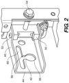
FIG. 2 depicts a height adjustable mounting foot assembly used in the configurations ofFIGs. 1a, 1b, and 1c ; -
FIG. 3a is a front elevation view of a teardrop slot used in the mounting system ofFIGs. 1a - 1c ; -
FIG. 3b is an isometric view of a button fastener attached to an electronic display device with the button fastener received in a slot of the mounting system ofFIGs. 1a - 1c ; -
FIG. 3c is an isometric view of a teardrop slot used in the mounting system ofFIGs. 1a - 1c ; -
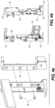
FIG. 4a is an exploded isometric view of horizontal coupling of multiple mounting systems as depicted inFIGs. 1a - 1c according to embodiments of the invention; -
FIG. 4b is an isometric view of vertical coupling of multiple mounting systems as depicted inFIGs. 1a - 1c according to embodiments of the invention; -
FIG. 5a depicts a mounting button attachable to an electronic display device and usable with the mounting system ofFIGs. 1a - 1c ; -
FIG. 5b depicts the mounting button ofFIG. 5a attached to an electronic display device; -
FIG. 6a is an isometric view of two mounting systems, one enabling three displays to be coupled vertically, and with one enabling a single display to be attached, the two mounting systems coupled horizontally to make an array; -
FIG. 6b is an isometric view of three mounting systems, each enabling three electronic displays to be coupled vertically, the three mounting systems coupled horizontally to make an array; -
FIG. 7a is a rear isometric view of the mounting systems ofFIG. 6b with electronic displays attached; -
FIG. 7a is a front isometric view of the mounting systems ofFIG. 6b with electronic displays attached; -
FIG. 8 is a rear isometric view of a 1 x 1 electronic display mount according to an embodiment of the invention; -
FIG. 9 is a partial rear isometric view of a mounting foot assembly according to an embodiment of the system of the invention; -
FIG. 10 is a rear isometric view of the mounting system ofFIG. 1b :-
FIG. 11 is a front isometric view of the mounting system ofFIG. 1c ; -
FIG. 12 is a front isometric view of an alternative embodiment of a mounting system according to an embodiment of the invention enabling vertically adjacent mounting of two electronic display devices; -
FIG. 13 is a front isometric view of a mounting foot of the device ofFIG. 12 ; -
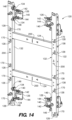
FIG. 14 is a front isometric view of the mounting system ofFIG. 12 enabling vertically adjacent mounting of three electronic display devices; -
FIG. 15 is a rear isometric view of the mounting system ofFIG. 12 enabling vertically adjacent mounting of three electronic display devices; -
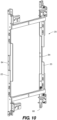
FIG. 16 is a front isometric view of the mounting system ofFIG. 12 enabling vertically adjacent mounting of four electronic display devices; -
FIG. 17a is a front elevation view of multiple mounts according toFIGs. 12 ,14 ,15 , or25 attached in a horizontal array of a predetermined shape; -
FIG. 17b is a front elevation view of multiple mounts according toFIGs. 12 ,14 ,15 , or25 attached in a horizontal array of a different predetermined shape; -
FIG. 18a is a front elevation view of multiple mounts according toFIGs. 12 ,14 ,15 , or25 attached in a horizontal array in the predetermined shape ofFIG. 17a , but with electronic displays attached; -
FIG. 18b is a front elevation view of multiple mounts according toFIGs. 12 ,14 ,15 , or25 attached in a horizontal array in the predetermined shape ofFIG. 17b , but with electronic displays attached; -
FIG. 19 is an exploded isometric view of horizontal attachment of the mounts ofFIG. 12 ; -
FIG. 20a is an exploded isometric view of vertical attachment of the mounts ofFIG. 12 ; -
FIG. 20b is an exploded isometric view of the portion ofFIG. 20a designated byinset 20b; -
FIG. 21a is a rear elevation view of the mounting system ofFIG. 12 with electronic displays attached; -
FIG. 21b is an elevation view of the portion ofFIG. 21a designated byinset 21b; -
FIG. 21c is an elevation view of the portion ofFIG. 21a designated byinset 21c; -
FIG. 21d is an elevation view of the portion ofFIG. 21a designated byinset 21d; -
FIG. 22a is a front isometric view of the mounting system ofFIG. 12 , depicting how a measuring device can be used in an embodiment of the invention; -
FIG. 22b is an isometric view of the portion ofFIG. 22a designated byinset 22b; -
FIG. 22c is a front isometric view of the mounting system ofFIG. 12 , depicting how a measuring device can be used in an embodiment of the invention; -
FIG. 22d is an isometric view of the portion ofFIG. 22c designated byinset 22d; -
FIG. 23a is a front elevation view of multiple mounts according toFIGs. 12 ,14 ,15 , or25 attached in a horizontal array of a different predetermined shape; -
FIG. 23b is a front elevation view of multiple mounts according toFIGs. 12 ,14 ,15 , or25 attached in a horizontal array of a different predetermined shape; -
FIG. 24a is a front elevation view of multiple mounts according toFIGs. 12 ,14 ,15 , or25 attached in a horizontal array in the predetermined shape ofFIG. 23a , but with electronic displays attached; -
FIG. 24b is a front elevation view of multiple mounts according toFIGs. 12 ,14 ,15 , or25 attached in a horizontal array in the predetermined shape ofFIG. 24b , but with electronic displays attached; -
FIG. 25 is a front isometric view of an alternative embodiment of a mounting system according to an embodiment of the invention enabling vertically adjacent mounting of two electronic display devices; -
FIG. 26a is a front elevation view of the mount ofFIG. 25 ; -
FIG. 26b is a partial phantom depiction of a limit structure for limiting horizontal sliding of displays during installation and use of the mounts ofFIGs. 1-25 ; -
FIG. 27a is a front isometric view of the device ofFIGs. 12 and25 with a side cover and electronic displays attached; and -
FIG. 27a is a rear exploded isometric view of the device ofFIG. 27a .
-
- While various embodiments are amenable to various modifications and alternative forms, specifics thereof have been shown by way of example in the drawings and will be described in detail. It should be understood, however, that the intention is not to limit the claimed inventions to the particular embodiments described. On the contrary, the intention is to cover all modifications, equivalents, and alternatives falling within the scope of the subject matter as defined by the claims.
- There is depicted in
FIGs. 1-11 a mounting system according to embodiments of the invention. Amount 20 for a single (1 x 1) electronic display device depicted inFIG. 1a and8 generally includesbrackets foot assemblies 26.Brackets teardrop slots 28 infront facing flanges 30.Side facing flanges 32 ofbrackets apertures receiving fasteners 34, andkeyhole slots 36. Cross-braces 24 are secured to each ofbrackets fasteners 38, and holdbrackets - As depicted in
FIGs. 2 and9 , mountingfoot assemblies 26 generally include mountingbracket 40 definingkeyhole slot 42 onlateral flange 44, andadjustment slots 46 onperpendicular flange 48.Adjustment block 50 is rigidly attached to mountingbracket 40 withfasteners 52, and receivesadjustment screw assembly 54. Mountingfoot assemblies 26 are adjustably coupled tobrackets adjustment screw assembly 54, and withfasteners 34 slidably received inadjustment slots 46 such that turningadjustment screw assembly 54 causeslateral flange 44 to be moved closer or further away fromfront facing flanges 30, depending on the direction of rotation ofadjustment screw 54. - In use, mount 20 can be attached to a wall with fasteners (not depicted) through
keyhole slots 42. The head of fastener already projecting from the wall can be advanced throughround portion 56 ofslot 42 and then mount 20 moved downward so that the fastener moves throughneck portion 58 and intolateral slot portion 60. From there, mount 20 can be slid horizontally, guided bylateral slot portion 60 so thatmount 20 can be adjusted for lateral position on the wall. The position offront facing flanges 30 can be adjusted relative to the wall by turningadjustment screw 54. As there are generally four mountingfeet 26 formount 20, thefront facing flanges 30 can be adjusted to enable an attached screen to be adjusted in roll and pitch relative to the wall and other displays mounted adjacent. -
Screen 62 is attached to mount 20 with-fastening buttons 64. Eachfastening button 64 hashead portion 66 andneck portion 68.Head portion 66 is advanced through roundedportion 70 ofteardrop slot 28, andscreen 62 moved downward so thatneck portion 68 moves throughnarrow portion 72 and intolateral slot 74. From there,screen 62 can be slid laterally withneck portion 68 guided inlateral slot 74. The position offastening button 64 inteardrop slot 28 can be adjusted and secured withpusher screw 76 received in apertures provided inbrackets stop block 78 as depicted inFIG.3 . - The system is modular and scalable for multiple vertically mounted displays as depicted in
FIGs. 1a - 1c .Brackets teardrop slots 28 located at appropriate positions onfront facing flanges 30 so as to enable two, three, or more displays to be mounted in a vertical array. Also,multiple mounts 20 can be positioned vertically with fasteners invertical slots 80 to link the mounts together vertically as depicted inFIG. 4b . In addition, mounts 20 can be linked horizontally as depicted inFIGs. 4a ,6a ,6b , and7a , withfasteners 82 throughkeyhole slots 36 and received in link bars 84. In this way, virtually unlimited configurations of horizontal and vertical arrays of screens can be achieved. - There is depicted in
FIGs. 12-27b alternative embodiments of a mounting system according to embodiments of the invention. Amount 120 for two electronic display devices, as depicted inFIGs. 12 and25 , generally includesbrackets foot assemblies 126.Brackets teardrop slots 128 infront facing flanges 130.Side facing flanges 132 ofbrackets apertures receiving fasteners 134, andkeyhole slots 36.Cross-braces 124 are secured to each ofbrackets fasteners 138, and holdbrackets - As depicted in
FIGs. 12 ,13 , and25 , mountingfoot assemblies 126 generally include mountingbracket 140, andattachment portion 141, with mountingbracket 140 definingteardrop slot 142 onlateral flange 144.Attachment portion 141 is secured to mountingbracket 140 withfasteners 143.Adjustment slots 146 are defined inperpendicular flanges 148 ofattachment portion 141.Adjustment block 150 is rigidly attached to mountingbracket 140 withfasteners 152, and receivesadjustment screw assembly 154 withadjustment nut 155 threaded onadjustment screw 157. Mountingfoot assemblies 126 are adjustably coupled tobrackets adjustment screw 154, and withfasteners 134 slidably received inadjustment slots 146 such that turningadjustment nut 155 onadjustment screw 154 causeslateral flange 144 to be moved closer or further away fromfront facing flanges 130, depending on the direction of rotation ofadjustment nut 155. - In use, mount 120 can be attached to a wall with fasteners (not depicted) through
teardrop slots 142. The head of such a fastener already projecting from the wall can be advanced throughlower portion 156 ofslot 42 and then mount 120 moved downward so that the fastener moves throughneck portion 158 and intolateral slot portion 160. From there, mount 120 can be slid horizontally, guided bylateral slot portion 160 so thatmount 120 can be adjusted for lateral position on the wall. The position offront facing flanges 130 can be adjusted inwardly and outwardly relative to the wall by turningadjustment nut 155. As there are generally four mountingfeet 126 formount 120, thefront facing flanges 130 can be adjusted to enable an attached electronic display to be adjusted in roll and pitch relative to the wall andother displays 62 mounted adjacent. - As with the embodiments depicted in
FIG. 1-11 ,electronic display 62 is attached to mount 120 withfastening buttons 64. Eachfastening button 64 hashead portion 66 andneck portion 68 as depicted inFIG. 5a .. Eachhead portion 66 is advanced through roundedportion 170 ofteardrop slots 128, andscreen 62 moved downward so thatneck portion 68 moves throughnarrow portion 172 and intolateral slot 174. From there,screen 62 can be slid laterally withneck portion 68 guided inlateral slot 174. The position offastening button 64 inteardrop slot 128 can be adjusted and secured withpusher screw 176 received in apertures provided inside facing flanges 132 ofbrackets Fig. 21a - 21d . Astop fastener 179 can be threaded in to limit lateral travel to a predetermined range as depicted inFIGs. 26a and 26b . - The system is scalable for multiple vertically mounted displays as depicted in
FIGs. 12 ,14 ,15 , and16 .Brackets teardrop slots 128 located at appropriate positions onfront facing flanges 130 so as to enable two, three, four, or more displays to be mounted in a vertical array. Also,multiple mounts 120 can be connected vertically withbrackets 190 secured withfasteners 192 as depicted inFIGs. 20a and 20b . - In addition, mounts 20 can be linked horizontally with
brackets 194 as depicted inFIG. 19 . As such, a virtually unlimited variety of overall array shapes of electronic displays can be achieved, with non-limiting exemplary embodiments depicted inFIGs, 17a, 17b ,18a, 18b ,23a, 23b ,24a, and 24b . - In embodiments,
slots 200 can be provided inbrackets cross-braces 124 to receive theperpendicular end 202 of acommon tape measure 204, as depicted inFIGs. 22a - 22d .Slots 200 can be located at the approximate mid-point of attachedelectronic displays 62 to enable easy measurement relative to a floor, ceiling, or adjacent walls of a structure and thereby enable precise positioning of the electronic displays. - As depicted in
FIGs. 27a and 27b ,side panels 206 can be attached tosystem 120 withbrackets 208 to provide for a finished appearance to the installation.
Claims (6)
- A system for mounting multiple electronic display devices to a wall of a structure, the system comprising:a first pair of spaced-apart brackets (22, 23, 122, 123), each bracket (22, 23, 122, 123) presenting a front flange (30, 130) defining a plurality of slots (28, 128), each slot (28, 128) adapted to receive a fastener (64) coupled to an electronic display (62) so as to attach the electronic display (62) to the bracket (22, 23, 122, 123); anda plurality of mounting feet (26, 126) operably coupled to each of the spaced-apart brackets (22, 23, 122, 123), each of the mounting feet (26, 126) adapted to attach to the wall and defining a slot (42, 142) enabling the mounting foot (26, 126) to shift parallel to a plane of the wall,each of the plurality of mounting feet (26, 126) being separately shiftable relative to the spaced-apart brackets (22, 23, 122, 123) with an adjustment screw assembly (54, 154) so as to enable the bracket (22, 23, 122, 123) to be selectively adjusted for position in a direction perpendicular to the wall,characterized in thateach of the plurality of mounting feet (26, 126) includes a mounting bracket (40, 140) defining the slot (42, 142) on a lateral flange (44, 144) and adjustment slots (46, 146) on a perpendicular flange (48, 148),wherein an adjustment block (50, 150) is rigidly attached to the mounting bracket (40, 140) with first fasteners (52, 152) and receives the adjustment screw assembly (54, 154),and wherein each of the plurality of mounting feet (26, 126) is adjustably coupled to the spaced-apart brackets (22, 23, 122, 123) with second fasteners (34, 134) slidably received in the adjustment slots (46, 146) such that turning the adjustment screw assembly (54, 154) causes the lateral flange (44, 144) to be moved relative to the front flange (30, 130).
- The system of claim 1, wherein the slot (42, 142) defined in each mounting foot is teardrop shaped.
- The system of any one of the preceding claims, wherein the slots (28, 128), defined in the spaced-apart brackets are teardrop shaped.
- The system of any one of the preceding claims further comprisinga second pair of spaced-apart brackets (122, 123), each of the second pair of brackets (122, 123) presenting a front flange (130) defining a plurality of slots (128), each slot (128) adapted to receive a fastener coupled to an electronic display so as to attach the electronic display to the second pair of spaced-apart brackets (122, 123) anda plurality of mounting feet (126) operably coupled to each of the second pair of spaced-apart brackets (122, 123), each of the mounting feet (126) adapted to attach to the wall and defining a slot (142) enabling the mounting foot (126) to shift parallel to a plane of the wall,each of the plurality of mounting feet (126) being separately shiftable relative to the spaced-apart brackets (122, 123) so as to enable the bracket (122, 123) to be selectively adjusted for position in a direction perpendicular to the wall,the second pair of spaced-apart apart brackets (122, 123) operably coupled to the first pair of spaced-apart brackets (22, 23, 122, 123) in a horizontally or vertically adjacent relation.
- The system of any one of the preceding claims wherein the first pair of spaced-apart brackets (22, 23, 122, 123) receives one, two, three, or four electronic displays.
- The system of any one of the preceding claims wherein each of the electronic displays is coupled with a plurality of fastening buttons (64).
Applications Claiming Priority (2)
| Application Number | Priority Date | Filing Date | Title |
|---|---|---|---|
| US201762599660P | 2017-12-15 | 2017-12-15 | |
| PCT/US2018/066094 WO2019118988A1 (en) | 2017-12-15 | 2018-12-17 | Screen mounting system |
Publications (3)
| Publication Number | Publication Date |
|---|---|
| EP3724547A1 EP3724547A1 (en) | 2020-10-21 |
| EP3724547A4 EP3724547A4 (en) | 2021-08-25 |
| EP3724547B1 true EP3724547B1 (en) | 2025-02-05 |
Family
ID=66820970
Family Applications (1)
| Application Number | Title | Priority Date | Filing Date |
|---|---|---|---|
| EP18888502.4A Active EP3724547B1 (en) | 2017-12-15 | 2018-12-17 | Screen mounting system |
Country Status (5)
| Country | Link |
|---|---|
| US (2) | US11882379B2 (en) |
| EP (1) | EP3724547B1 (en) |
| CN (1) | CN111699338A (en) |
| CA (1) | CA3085821A1 (en) |
| WO (1) | WO2019118988A1 (en) |
Families Citing this family (9)
| Publication number | Priority date | Publication date | Assignee | Title |
|---|---|---|---|---|
| WO2020154385A1 (en) * | 2019-01-24 | 2020-07-30 | Steelcase Inc. | Display support system and method for the use thereof |
| US20210402280A1 (en) * | 2020-05-26 | 2021-12-30 | James Karnes | Modular adjustable frame |
| KR102404360B1 (en) * | 2020-10-23 | 2022-06-02 | 엘지전자 주식회사 | Display control module and display device including same |
| CN113294663B (en) * | 2021-05-31 | 2021-10-15 | 深圳市金乾象科技有限公司 | Camera antidetonation device is patrolled and examined to piping lane |
| LU500750B1 (en) * | 2021-10-18 | 2023-04-18 | Barco Control Rooms Gmbh | Support structure with improved alignment for frames of a tiled display wall |
| KR20230100423A (en) * | 2021-12-28 | 2023-07-05 | 삼성전자주식회사 | Display apparatus |
| NL2035497B1 (en) * | 2023-07-28 | 2025-02-11 | Vogels Ip B V | System for installing a video wall |
| US12622520B2 (en) * | 2024-05-21 | 2026-05-12 | Jolly Innovation Technology Co., Ltd. | Mounting assembly and apparatus |
| US20260071720A1 (en) | 2024-09-06 | 2026-03-12 | Legrand Av Inc. | Universal mounting system for electronic display array |
Family Cites Families (37)
| Publication number | Priority date | Publication date | Assignee | Title |
|---|---|---|---|---|
| US6102348A (en) * | 1999-04-19 | 2000-08-15 | Lucasey Manufacturing Company | Appliance mounting device |
| US6484987B2 (en) * | 2000-12-29 | 2002-11-26 | Bellsouth Intellectual Property Corporation | Mounting bracket |
| KR100461184B1 (en) * | 2002-05-28 | 2004-12-13 | 삼성전자주식회사 | Display |
| US6604722B1 (en) * | 2002-06-10 | 2003-08-12 | Seng-Ling Tan | Display support |
| KR100867108B1 (en) * | 2002-09-19 | 2008-11-06 | 삼성전자주식회사 | Display Mounting Device and Jig for Mounting Device |
| US20040211870A1 (en) * | 2003-04-11 | 2004-10-28 | Jeff Bremmon | Universal mount bracket |
| US20050087661A1 (en) * | 2003-10-23 | 2005-04-28 | Rabenius John A. | Method and apparatus for mounting flat screen television on vertically oriented surface |
| KR100968455B1 (en) * | 2004-01-09 | 2010-07-07 | 삼성전자주식회사 | Display device |
| USD530595S1 (en) * | 2004-09-21 | 2006-10-24 | Peerless Industries, Inc. | Mounting system for a display unit |
| US20060065800A1 (en) * | 2004-09-29 | 2006-03-30 | Jeff Bremmon | Universal mount for flat panel displays |
| US7712717B2 (en) * | 2005-05-23 | 2010-05-11 | Vantage Point Products Corporation | Display mounting apparatus |
| TWM278990U (en) * | 2005-05-27 | 2005-10-21 | Hannspree Inc | Suspension structure of electronic device |
| US20060291152A1 (en) * | 2005-06-06 | 2006-12-28 | Jeff Bremmon | Mounting device for flat-panel display |
| KR100743746B1 (en) * | 2005-07-08 | 2007-07-27 | 엘지전자 주식회사 | Display device angle adjuster |
| EP1837583A3 (en) * | 2006-03-22 | 2009-08-05 | Samsung Electronics Co., Ltd. | Supporting device of display unit |
| US7963489B2 (en) * | 2006-08-10 | 2011-06-21 | Peerless Industries, Inc. | Extension mechanism for a mounting system |
| USD560672S1 (en) * | 2006-08-31 | 2008-01-29 | Omnimount Systems, Inc. | Small low-profile tiltable mount for flat panel displays |
| US7871048B2 (en) * | 2006-12-28 | 2011-01-18 | Bell'o International Corp. | Flat panel display mounting system |
| US8456808B2 (en) * | 2007-09-06 | 2013-06-04 | Milestone Av Technologies Llc | Display wall mount with elastomeric spring latch and post-installation height adjustment and leveling feature |
| US7823847B2 (en) * | 2008-01-04 | 2010-11-02 | Milestone Av Technologies Llc | Display mount with post-installation adjustment features |
| US8891249B2 (en) * | 2009-01-07 | 2014-11-18 | Milestone Av Technologies Llc | Display mount with adjustable position tilt axis |
| US7878473B1 (en) * | 2009-11-23 | 2011-02-01 | Clo Systems, Llc | Multi-functioning mount system for a monitor |
| KR101698309B1 (en) * | 2010-01-07 | 2017-01-20 | 삼성전자주식회사 | Supporting device for display unit |
| US8333355B2 (en) * | 2010-02-12 | 2012-12-18 | Peerless Industries, Inc. | Adjustable display mount |
| KR101083991B1 (en) * | 2010-07-05 | 2011-11-16 | (주)한국킹유전자 | Multi Vision Installation Device |
| US20130048812A1 (en) | 2011-08-25 | 2013-02-28 | Anthony Lozano | Flat panel mounting system |
| US10104963B2 (en) | 2013-06-07 | 2018-10-23 | Milestone Av Technologies Llc | Wall mount system |
| CN104100821B (en) * | 2014-07-24 | 2015-12-02 | 苏州市荣美工贸有限公司 | A kind of adjustable LCD TVs/mount bracket for flat-panel display |
| KR101608309B1 (en) | 2015-02-27 | 2016-04-04 | 주식회사 일흥 엔터 프라이즈 | Order type Seat Thermic rays |
| US20160379530A1 (en) * | 2015-06-26 | 2016-12-29 | Britework LLC | Compression-Fit Digital Display Mounting System |
| WO2017044622A1 (en) | 2015-09-09 | 2017-03-16 | Peerless Industries, Inc. | Video wall mount |
| CN205655069U (en) * | 2016-05-12 | 2016-10-19 | 同辉佳视(北京)信息技术股份有限公司 | Wall -hanging joggle truss |
| KR101695929B1 (en) * | 2016-05-31 | 2017-01-13 | 주식회사 제이비에이치 | Wall mount for multi-display |
| CN205781887U (en) * | 2016-07-05 | 2016-12-07 | 牟晋阳 | Computer display wall hanging rack |
| KR102519930B1 (en) * | 2016-07-07 | 2023-04-11 | 삼성전자주식회사 | Display apparatus |
| CN206018223U (en) * | 2016-09-05 | 2017-03-15 | 大道网络(上海)股份有限公司 | A kind of multi-screen splicing display unit device for installing and adjusting |
| CN107387995A (en) * | 2017-08-22 | 2017-11-24 | 苏州唐浦电子贸易有限公司 | A kind of display rack with intelligent fan |
-
2018
- 2018-12-17 CA CA3085821A patent/CA3085821A1/en active Pending
- 2018-12-17 US US16/772,924 patent/US11882379B2/en active Active
- 2018-12-17 WO PCT/US2018/066094 patent/WO2019118988A1/en not_active Ceased
- 2018-12-17 EP EP18888502.4A patent/EP3724547B1/en active Active
- 2018-12-17 CN CN201880086706.0A patent/CN111699338A/en active Pending
-
2024
- 2024-01-02 US US18/401,890 patent/US12262141B2/en active Active
Also Published As
| Publication number | Publication date |
|---|---|
| US20240333868A1 (en) | 2024-10-03 |
| CN111699338A (en) | 2020-09-22 |
| WO2019118988A1 (en) | 2019-06-20 |
| CA3085821A1 (en) | 2019-06-20 |
| EP3724547A4 (en) | 2021-08-25 |
| US11882379B2 (en) | 2024-01-23 |
| US12262141B2 (en) | 2025-03-25 |
| EP3724547A1 (en) | 2020-10-21 |
| US20200412998A1 (en) | 2020-12-31 |
Similar Documents
| Publication | Publication Date | Title |
|---|---|---|
| US12262141B2 (en) | Screen mounting system | |
| US8944393B2 (en) | Fixing structure and fixing method of multi-screen display unit | |
| JP5105123B2 (en) | Multi-screen display device fixing structure and fixing method | |
| US8356718B2 (en) | Server rack assembly | |
| US8251325B2 (en) | Adjustable display bracket | |
| US8408505B2 (en) | Display support device and display using the same | |
| EP3366973B1 (en) | Wall mount and display device | |
| CN109155119B (en) | Display device | |
| US8939414B2 (en) | Backdrop for wall-mounted flat panel display installation and method | |
| WO2014068324A1 (en) | Display screen signage | |
| CN101631984A (en) | Visual Display Unit Mounting Device | |
| US10197836B2 (en) | Spliced display and display system | |
| US20160003411A1 (en) | Support structure for an article, method of mounting the support structure, and support bracket | |
| KR101551730B1 (en) | Multi display install mount | |
| WO2021082173A1 (en) | Display screen support, display screen assembly and method for mounting display screen assembly | |
| US11788677B2 (en) | Hanger and display device | |
| KR20130003612U (en) | Monitor Support Device | |
| TW201414404A (en) | Rack frame of server with power socket | |
| CN203717587U (en) | Riveting stud, display device and supporting beam and supporting part therefor | |
| KR20130003626U (en) | Monitor Support Device | |
| CN224003409U (en) | Desktop type mounting bracket and display device | |
| KR20140123806A (en) | Supporting device for display apparatus | |
| CN201477893U (en) | Adjustable structure for coating inside pipe | |
| CN203054380U (en) | Integral back plate for liquid crystal display screen | |
| CN204465717U (en) | Display device and its module adapter bracket |
Legal Events
| Date | Code | Title | Description |
|---|---|---|---|
| STAA | Information on the status of an ep patent application or granted ep patent |
Free format text: STATUS: THE INTERNATIONAL PUBLICATION HAS BEEN MADE |
|
| PUAI | Public reference made under article 153(3) epc to a published international application that has entered the european phase |
Free format text: ORIGINAL CODE: 0009012 |
|
| STAA | Information on the status of an ep patent application or granted ep patent |
Free format text: STATUS: REQUEST FOR EXAMINATION WAS MADE |
|
| 17P | Request for examination filed |
Effective date: 20200625 |
|
| AK | Designated contracting states |
Kind code of ref document: A1 Designated state(s): AL AT BE BG CH CY CZ DE DK EE ES FI FR GB GR HR HU IE IS IT LI LT LU LV MC MK MT NL NO PL PT RO RS SE SI SK SM TR |
|
| AX | Request for extension of the european patent |
Extension state: BA ME |
|
| DAV | Request for validation of the european patent (deleted) | ||
| DAX | Request for extension of the european patent (deleted) | ||
| A4 | Supplementary search report drawn up and despatched |
Effective date: 20210727 |
|
| RIC1 | Information provided on ipc code assigned before grant |
Ipc: F16M 13/02 20060101AFI20210721BHEP Ipc: F16M 11/04 20060101ALI20210721BHEP |
|
| GRAP | Despatch of communication of intention to grant a patent |
Free format text: ORIGINAL CODE: EPIDOSNIGR1 |
|
| STAA | Information on the status of an ep patent application or granted ep patent |
Free format text: STATUS: GRANT OF PATENT IS INTENDED |
|
| INTG | Intention to grant announced |
Effective date: 20240722 |
|
| GRAS | Grant fee paid |
Free format text: ORIGINAL CODE: EPIDOSNIGR3 |
|
| RAP3 | Party data changed (applicant data changed or rights of an application transferred) |
Owner name: LEGRAND AV INC. |
|
| GRAA | (expected) grant |
Free format text: ORIGINAL CODE: 0009210 |
|
| STAA | Information on the status of an ep patent application or granted ep patent |
Free format text: STATUS: THE PATENT HAS BEEN GRANTED |
|
| AK | Designated contracting states |
Kind code of ref document: B1 Designated state(s): AL AT BE BG CH CY CZ DE DK EE ES FI FR GB GR HR HU IE IS IT LI LT LU LV MC MK MT NL NO PL PT RO RS SE SI SK SM TR |
|
| REG | Reference to a national code |
Ref country code: GB Ref legal event code: FG4D |
|
| REG | Reference to a national code |
Ref country code: CH Ref legal event code: EP |
|
| REG | Reference to a national code |
Ref country code: IE Ref legal event code: FG4D |
|
| REG | Reference to a national code |
Ref country code: DE Ref legal event code: R096 Ref document number: 602018078990 Country of ref document: DE |
|
| REG | Reference to a national code |
Ref country code: NL Ref legal event code: FP |
|
| PG25 | Lapsed in a contracting state [announced via postgrant information from national office to epo] |
Ref country code: RS Free format text: LAPSE BECAUSE OF FAILURE TO SUBMIT A TRANSLATION OF THE DESCRIPTION OR TO PAY THE FEE WITHIN THE PRESCRIBED TIME-LIMIT Effective date: 20250505 |
|
| PG25 | Lapsed in a contracting state [announced via postgrant information from national office to epo] |
Ref country code: FI Free format text: LAPSE BECAUSE OF FAILURE TO SUBMIT A TRANSLATION OF THE DESCRIPTION OR TO PAY THE FEE WITHIN THE PRESCRIBED TIME-LIMIT Effective date: 20250205 |
|
| PG25 | Lapsed in a contracting state [announced via postgrant information from national office to epo] |
Ref country code: PL Free format text: LAPSE BECAUSE OF FAILURE TO SUBMIT A TRANSLATION OF THE DESCRIPTION OR TO PAY THE FEE WITHIN THE PRESCRIBED TIME-LIMIT Effective date: 20250205 |
|
| PG25 | Lapsed in a contracting state [announced via postgrant information from national office to epo] |
Ref country code: ES Free format text: LAPSE BECAUSE OF FAILURE TO SUBMIT A TRANSLATION OF THE DESCRIPTION OR TO PAY THE FEE WITHIN THE PRESCRIBED TIME-LIMIT Effective date: 20250205 |
|
| REG | Reference to a national code |
Ref country code: LT Ref legal event code: MG9D |
|
| PG25 | Lapsed in a contracting state [announced via postgrant information from national office to epo] |
Ref country code: IS Free format text: LAPSE BECAUSE OF FAILURE TO SUBMIT A TRANSLATION OF THE DESCRIPTION OR TO PAY THE FEE WITHIN THE PRESCRIBED TIME-LIMIT Effective date: 20250605 Ref country code: NO Free format text: LAPSE BECAUSE OF FAILURE TO SUBMIT A TRANSLATION OF THE DESCRIPTION OR TO PAY THE FEE WITHIN THE PRESCRIBED TIME-LIMIT Effective date: 20250505 |
|
| PG25 | Lapsed in a contracting state [announced via postgrant information from national office to epo] |
Ref country code: HR Free format text: LAPSE BECAUSE OF FAILURE TO SUBMIT A TRANSLATION OF THE DESCRIPTION OR TO PAY THE FEE WITHIN THE PRESCRIBED TIME-LIMIT Effective date: 20250205 |
|
| PG25 | Lapsed in a contracting state [announced via postgrant information from national office to epo] |
Ref country code: PT Free format text: LAPSE BECAUSE OF FAILURE TO SUBMIT A TRANSLATION OF THE DESCRIPTION OR TO PAY THE FEE WITHIN THE PRESCRIBED TIME-LIMIT Effective date: 20250605 Ref country code: LV Free format text: LAPSE BECAUSE OF FAILURE TO SUBMIT A TRANSLATION OF THE DESCRIPTION OR TO PAY THE FEE WITHIN THE PRESCRIBED TIME-LIMIT Effective date: 20250205 |
|
| PG25 | Lapsed in a contracting state [announced via postgrant information from national office to epo] |
Ref country code: BG Free format text: LAPSE BECAUSE OF FAILURE TO SUBMIT A TRANSLATION OF THE DESCRIPTION OR TO PAY THE FEE WITHIN THE PRESCRIBED TIME-LIMIT Effective date: 20250205 Ref country code: GR Free format text: LAPSE BECAUSE OF FAILURE TO SUBMIT A TRANSLATION OF THE DESCRIPTION OR TO PAY THE FEE WITHIN THE PRESCRIBED TIME-LIMIT Effective date: 20250506 |
|
| REG | Reference to a national code |
Ref country code: AT Ref legal event code: MK05 Ref document number: 1764939 Country of ref document: AT Kind code of ref document: T Effective date: 20250205 |
|
| PG25 | Lapsed in a contracting state [announced via postgrant information from national office to epo] |
Ref country code: SE Free format text: LAPSE BECAUSE OF FAILURE TO SUBMIT A TRANSLATION OF THE DESCRIPTION OR TO PAY THE FEE WITHIN THE PRESCRIBED TIME-LIMIT Effective date: 20250205 |
|
| PG25 | Lapsed in a contracting state [announced via postgrant information from national office to epo] |
Ref country code: SM Free format text: LAPSE BECAUSE OF FAILURE TO SUBMIT A TRANSLATION OF THE DESCRIPTION OR TO PAY THE FEE WITHIN THE PRESCRIBED TIME-LIMIT Effective date: 20250205 |
|
| PG25 | Lapsed in a contracting state [announced via postgrant information from national office to epo] |
Ref country code: DK Free format text: LAPSE BECAUSE OF FAILURE TO SUBMIT A TRANSLATION OF THE DESCRIPTION OR TO PAY THE FEE WITHIN THE PRESCRIBED TIME-LIMIT Effective date: 20250205 |
|
| PG25 | Lapsed in a contracting state [announced via postgrant information from national office to epo] |
Ref country code: AT Free format text: LAPSE BECAUSE OF FAILURE TO SUBMIT A TRANSLATION OF THE DESCRIPTION OR TO PAY THE FEE WITHIN THE PRESCRIBED TIME-LIMIT Effective date: 20250205 |
|
| PG25 | Lapsed in a contracting state [announced via postgrant information from national office to epo] |
Ref country code: EE Free format text: LAPSE BECAUSE OF FAILURE TO SUBMIT A TRANSLATION OF THE DESCRIPTION OR TO PAY THE FEE WITHIN THE PRESCRIBED TIME-LIMIT Effective date: 20250205 Ref country code: CZ Free format text: LAPSE BECAUSE OF FAILURE TO SUBMIT A TRANSLATION OF THE DESCRIPTION OR TO PAY THE FEE WITHIN THE PRESCRIBED TIME-LIMIT Effective date: 20250205 |
|
| PG25 | Lapsed in a contracting state [announced via postgrant information from national office to epo] |
Ref country code: RO Free format text: LAPSE BECAUSE OF FAILURE TO SUBMIT A TRANSLATION OF THE DESCRIPTION OR TO PAY THE FEE WITHIN THE PRESCRIBED TIME-LIMIT Effective date: 20250205 |
|
| PG25 | Lapsed in a contracting state [announced via postgrant information from national office to epo] |
Ref country code: SK Free format text: LAPSE BECAUSE OF FAILURE TO SUBMIT A TRANSLATION OF THE DESCRIPTION OR TO PAY THE FEE WITHIN THE PRESCRIBED TIME-LIMIT Effective date: 20250205 |
|
| REG | Reference to a national code |
Ref country code: CH Ref legal event code: W10 Free format text: ST27 STATUS EVENT CODE: U-0-0-W10-W00 (AS PROVIDED BY THE NATIONAL OFFICE) Effective date: 20251105 |
|
| REG | Reference to a national code |
Ref country code: DE Ref legal event code: R097 Ref document number: 602018078990 Country of ref document: DE |
|
| RAP4 | Party data changed (patent owner data changed or rights of a patent transferred) |
Owner name: LEGRAND AV INC. |
|
| PLBE | No opposition filed within time limit |
Free format text: ORIGINAL CODE: 0009261 |
|
| STAA | Information on the status of an ep patent application or granted ep patent |
Free format text: STATUS: NO OPPOSITION FILED WITHIN TIME LIMIT |
|
| PGFP | Annual fee paid to national office [announced via postgrant information from national office to epo] |
Ref country code: DE Payment date: 20251211 Year of fee payment: 8 |
|
| PGFP | Annual fee paid to national office [announced via postgrant information from national office to epo] |
Ref country code: GB Payment date: 20251219 Year of fee payment: 8 |
|
| 26N | No opposition filed |
Effective date: 20251106 |
|
| PGFP | Annual fee paid to national office [announced via postgrant information from national office to epo] |
Ref country code: IT Payment date: 20251223 Year of fee payment: 8 |
|
| PGFP | Annual fee paid to national office [announced via postgrant information from national office to epo] |
Ref country code: FR Payment date: 20251229 Year of fee payment: 8 Ref country code: NL Payment date: 20251219 Year of fee payment: 8 |