EP3724494B1 - Wind turbine nacelle cooling - Google Patents
Wind turbine nacelle cooling Download PDFInfo
- Publication number
- EP3724494B1 EP3724494B1 EP18829721.2A EP18829721A EP3724494B1 EP 3724494 B1 EP3724494 B1 EP 3724494B1 EP 18829721 A EP18829721 A EP 18829721A EP 3724494 B1 EP3724494 B1 EP 3724494B1
- Authority
- EP
- European Patent Office
- Prior art keywords
- nacelle
- wind turbine
- conduit
- air
- turbine according
- Prior art date
- Legal status (The legal status is an assumption and is not a legal conclusion. Google has not performed a legal analysis and makes no representation as to the accuracy of the status listed.)
- Active
Links
Images



Classifications
-
- F—MECHANICAL ENGINEERING; LIGHTING; HEATING; WEAPONS; BLASTING
- F03—MACHINES OR ENGINES FOR LIQUIDS; WIND, SPRING, OR WEIGHT MOTORS; PRODUCING MECHANICAL POWER OR A REACTIVE PROPULSIVE THRUST, NOT OTHERWISE PROVIDED FOR
- F03D—WIND MOTORS
- F03D80/00—Details, components or accessories not provided for in groups F03D1/00 - F03D17/00
- F03D80/60—Cooling or heating of wind motors
-
- F—MECHANICAL ENGINEERING; LIGHTING; HEATING; WEAPONS; BLASTING
- F03—MACHINES OR ENGINES FOR LIQUIDS; WIND, SPRING, OR WEIGHT MOTORS; PRODUCING MECHANICAL POWER OR A REACTIVE PROPULSIVE THRUST, NOT OTHERWISE PROVIDED FOR
- F03D—WIND MOTORS
- F03D80/00—Details, components or accessories not provided for in groups F03D1/00 - F03D17/00
- F03D80/80—Arrangement of components within nacelles or towers
- F03D80/88—Arrangement of components within nacelles or towers of mechanical components
-
- F—MECHANICAL ENGINEERING; LIGHTING; HEATING; WEAPONS; BLASTING
- F03—MACHINES OR ENGINES FOR LIQUIDS; WIND, SPRING, OR WEIGHT MOTORS; PRODUCING MECHANICAL POWER OR A REACTIVE PROPULSIVE THRUST, NOT OTHERWISE PROVIDED FOR
- F03D—WIND MOTORS
- F03D9/00—Adaptations of wind motors for special use; Combinations of wind motors with apparatus driven thereby; Wind motors specially adapted for installation in particular locations
- F03D9/20—Wind motors characterised by the driven apparatus
- F03D9/25—Wind motors characterised by the driven apparatus the apparatus being an electrical generator
-
- F—MECHANICAL ENGINEERING; LIGHTING; HEATING; WEAPONS; BLASTING
- F05—INDEXING SCHEMES RELATING TO ENGINES OR PUMPS IN VARIOUS SUBCLASSES OF CLASSES F01-F04
- F05B—INDEXING SCHEME RELATING TO WIND, SPRING, WEIGHT, INERTIA OR LIKE MOTORS, TO MACHINES OR ENGINES FOR LIQUIDS COVERED BY SUBCLASSES F03B, F03D AND F03G
- F05B2240/00—Components
- F05B2240/10—Stators
- F05B2240/14—Casings, housings, nacelles, gondels or the like, protecting or supporting assemblies there within
-
- F—MECHANICAL ENGINEERING; LIGHTING; HEATING; WEAPONS; BLASTING
- F05—INDEXING SCHEMES RELATING TO ENGINES OR PUMPS IN VARIOUS SUBCLASSES OF CLASSES F01-F04
- F05B—INDEXING SCHEME RELATING TO WIND, SPRING, WEIGHT, INERTIA OR LIKE MOTORS, TO MACHINES OR ENGINES FOR LIQUIDS COVERED BY SUBCLASSES F03B, F03D AND F03G
- F05B2260/00—Function
- F05B2260/20—Heat transfer, e.g. cooling
-
- Y—GENERAL TAGGING OF NEW TECHNOLOGICAL DEVELOPMENTS; GENERAL TAGGING OF CROSS-SECTIONAL TECHNOLOGIES SPANNING OVER SEVERAL SECTIONS OF THE IPC; TECHNICAL SUBJECTS COVERED BY FORMER USPC CROSS-REFERENCE ART COLLECTIONS [XRACs] AND DIGESTS
- Y02—TECHNOLOGIES OR APPLICATIONS FOR MITIGATION OR ADAPTATION AGAINST CLIMATE CHANGE
- Y02B—CLIMATE CHANGE MITIGATION TECHNOLOGIES RELATED TO BUILDINGS, e.g. HOUSING, HOUSE APPLIANCES OR RELATED END-USER APPLICATIONS
- Y02B10/00—Integration of renewable energy sources in buildings
- Y02B10/30—Wind power
-
- Y—GENERAL TAGGING OF NEW TECHNOLOGICAL DEVELOPMENTS; GENERAL TAGGING OF CROSS-SECTIONAL TECHNOLOGIES SPANNING OVER SEVERAL SECTIONS OF THE IPC; TECHNICAL SUBJECTS COVERED BY FORMER USPC CROSS-REFERENCE ART COLLECTIONS [XRACs] AND DIGESTS
- Y02—TECHNOLOGIES OR APPLICATIONS FOR MITIGATION OR ADAPTATION AGAINST CLIMATE CHANGE
- Y02E—REDUCTION OF GREENHOUSE GAS [GHG] EMISSIONS, RELATED TO ENERGY GENERATION, TRANSMISSION OR DISTRIBUTION
- Y02E10/00—Energy generation through renewable energy sources
- Y02E10/70—Wind energy
- Y02E10/72—Wind turbines with rotation axis in wind direction
Definitions
- Cool external air is drawn into the nacelle through openings in the nacelle and directed via conduits or ducts over or into the components where heat is exchanged with the air.
- the warmed air is then directed out of the nacelle via exit conduits or ducts and expelled through air outlets.
- the present invention seeks to provide a nacelle structure which addresses these challenges.
- US2012/025541 describes a nacelle configuration where outside air is drawn via an inlet through a double-walled nacelle cover and used to guide cool air to provide cooling to the nacelle interior space via heat transfer through the walls, and is eventually directed after passing around the nacelle to a blade pitch system and exiting via the blades.
- US2010/061853 teaches drawing external air into the nacelle where it is led by an conduit through the nacelle, with component heat exchangers extending into the conduit to cool the components, and the warmed air then being led to the nacelle interior to provide space heating.
- US2012/032449 directs cool external air at a direct drive generator, with internal guide plates serving to guide air specifically to the generator outer edges.
- a wind turbine comprising a nacelle which houses operative components which in use generate heat, the nacelle including an external nacelle cover to form an enclosure, and provided with an internal panel which overlies a bottom cover of the external cover to define therewith a conduit which underlies heat generating components for directing external air to the heat generating operative components, wherein respective ducts are connected between the internal panel and one or more heat generating operative components to direct the cooling air thereto from the conduit.
- Such air cooling may be relevant for a variety of operative components such as the converter, and transformer. It may also be used in connection with the gearbox and generator.
- the panel may extend laterally across substantially the entire width of the bottom cover part.
- the external cover includes an air inlet which opens into the conduit, preferably at a forward region of the bottom cover to the front of the tower opening.
- the conduit extends from this forward region, around sides of the tower opening at which the nacelle is connected to the tower, towards the rear of the nacelle.
- Connection to the conduit may be made at various points along the conduit to respective components via the ducts in order to receive cooling air.
- short ducts or tubing may be connected between the internal panel and one or more heat generating operative components, for example to the air inlet manifold thereof, to direct the cooling air thereto from the conduit.
- Fans are provided at various positions in the conduit or at connections with the conduit to the components, to draw air into and along the conduit and direct it to the various operative components to be cooled.
- the "forward” direction is taken to be the direction in the nacelle towards the rotor and the “rearward” the opposite direction which is away from the rotor.
- the internal panel may be formed on an underside which faces the external cover with partitions which serve to direct the flow of cooling air in a defined path or paths and to specific points at which connection is made to particular components to be cooled.
- the internal panel may be configured to have a modular form whereby a single panel may be manufactured for use with a variety of nacelle layouts, and then the panel adapted for use with a particular nacelle layout. To this end it may be formed with a plurality of partitions extending laterally and longitudinally, which partitions are selectively removable prior to assembly in order to define a desired flow path for a particular configuration of nacelle and its heat generating operative components.
- the air directing function may be combined with a liquid spillage collecting function.
- the internal panel is formed with an upstanding rim near its periphery to upwardly define a liquid collecting receptacle to collect liquid leakage or spillage from liquid containing components.
- a number of receptacles may be defined by upstanding rims associated with individual components. These may be separate from each other or may be interconnected to allow fluid to flow between receptacles.
- the internal cover part may further define a channel region at its lateral periphery to collect any liquid passing down the side walls of the nacelle cover, for example as condensation.
- a conduit over the bottom cover of the nacelle, this may instead or in addition be provided at the nacelle sidewalls. Internal panels may be provided which laterally overlie the sidewalls. The inlets for the conduit are again preferably near a forward end of the nacelle extending rearwardly along the nacelle.
- the invention provides a method of cooling heat generating operative components in a wind turbine having the construction as defined above, the method comprising drawing air into the conduit from the exterior and directing it via the conduit and the ducts to the heat generating operative components.
- cooling air is taken in through an inlet at or near a forward end of the nacelle into the conduit, and expelled from the nacelle after passing through or over one or more heat-generating components.
- FIG. 1 a wind turbine nacelle structure is shown which incorporates a cooling arrangement according to an embodiment of the present invention.
- the wind turbine includes a nacelle 2 which houses the main operative components of the turbine as further discussed below.
- the nacelle sits atop a tower 4 which extends from a ground mounted foundation (not shown).
- a rotor 6 comprises a number of blades 8 (typically three blades) which are mounted on a central hub 10.
- the hub 10 is connected at a forward end of main shaft which is supported on a main bearing.
- the main bearing housing is shown schematically by 12 in the figure.
- the main shaft extends into gearbox and generator collectively indicated 14, which may comprise separate components or as a combined structure.
- the gearbox serves to increase the rotational speed to an appropriate degree for turning generator, whilst the generator serves to convert the rotational energy into electrical energy, as is well known in the art.
- the main operative components mentioned above all produce a degree of unwanted waste heat when in operation, the mechanical components such as the gearbox due to frictional forces, the generator as an electro-mechanical converter due to both mechanical friction and electrical losses, and the transformer due to electrical losses.
- the nacelle is arranged so that a portion of the nacelle cover 20 itself provides part of the cooling air conduit-defining structure. As shown in Figure 1 an air conduit is defined between a bottom cover 22 of the nacelle 20 and an internal panel 24 which vertically overlies and extends parallel to the bottom cover 22, in essence forming a double-walled structure.
- the air inlet 26 extends across a significant width of the bottom cover 24 in order to maximise the opening area and reduce the pressure drop as air is drawn in, and is covered by a grill or mesh to limit or prevent the ingress of rain, particles, insects or other foreign material or debris.
- An additional inlet region 28 may be provided to the rear of the yaw opening.
- the conduit supplies cooling air to one or more operative components.
- air is supplied to converter 16, the internal panel 24 opening directly or indirectly via a short additional region of ducting 29 into the cooling air supply manifold of the converter 16.
- Fans are provided in order to draw air into and along the conduit, at the inlet 26 and/or at positions along the length of the conduit and/or at the points at which air is drawn off the conduit.
- a fan 30 is located at the converter 16 between the ducting 29 and converter 16.
- air may exit the converter and nacelle via a dedicated outlet through a wall of the nacelle. Alternatively, it may be returned into the air conduit to mix with the fresh air or led into the transformer enclosure from where exits the nacelle.
- the conduit further directs air to the transformer 18, opening directly into, or indirectly as illustrated via a short additional duct 35 into the transformer enclosure driven by fan 37.
- An air outlet 33 is provided at the nacelle rear, preferably at an upper region of the rear panel through which the heated air exits the transformer enclosure and nacelle and is exhausted to the external environment.
- the internal panel 24 is further provided with functionality as a liquid spillage tray.
- the internal panel 24 is shaped to define upwardly a shallow liquid-containing receptacle, having an upwardly extending rim 34 so that liquid which might inadvertently leak from an operative component, such as lubricating or cooling oil or water or other cooling medium, may be constrained in order to be collected and removed during a service operation, and prevented from leaking outside the nacelle.
- Figure 7 shows schematically use of the internal panel 24 as a spillage tray collecting liquid leaked from gearbox or generator 14.
- the bottom cover 22 may be formed with an internally protruding lip 36.
- conduits may be defined between a side wall or walls of the nacelle cover and an internal side panel or panels which laterally overlie and extend parallel to the side wall or side walls.
- This configuration may be combined with the first embodiment described above; as shown in Figure 7 the side wall 40 is provided with an internal side panel 42 defining therebetween a rearwardly extending conduit.
- an inlet region likewise covered in a grill or mesh to prevent ingress of unwanted material, the conduit extending along the length of the sidewall or side walls towards the rear of the nacelle.
- One or more internal ducts are connected to the conduit to direct cooling air into operative components such as the transformer and converter.
- conduit construction may be used to provide a degree of air cooling of components such as gearbox and generator which are liquid cooled; for example, the oil or water cooling circuits may employ heat exchangers which are then air cooled with air from the conduit. Whilst the air conduit may not supply all the cooling need for such components, it may contribute to such cooling.
Landscapes
- Engineering & Computer Science (AREA)
- Life Sciences & Earth Sciences (AREA)
- Sustainable Development (AREA)
- Sustainable Energy (AREA)
- Chemical & Material Sciences (AREA)
- Combustion & Propulsion (AREA)
- Mechanical Engineering (AREA)
- General Engineering & Computer Science (AREA)
- Physics & Mathematics (AREA)
- Thermal Sciences (AREA)
- Wind Motors (AREA)
Description
- The present invention relates to a wind turbine nacelle which is adapted to provide cooling air for cooling heat-generating components, and to a method of nacelle cooling.
- Wind turbines include various operative components which generate significant amounts of unwanted waste heat. These include major mechanical components such as components of the drive train where the origin of the heat is internal frictional forces, and electrical systems where heat is generated within individual electronic and electrical components themselves. Examples of such major electrical systems include the electrical power converters and the transformers.
- It is conventional that various heat-generating operative components are cooled by air. Cool external air is drawn into the nacelle through openings in the nacelle and directed via conduits or ducts over or into the components where heat is exchanged with the air. The warmed air is then directed out of the nacelle via exit conduits or ducts and expelled through air outlets.
- With advancing technological developments, wind turbines of ever greater power rating are provided. With increased power delivery, the heat production of components also increases. Moreover, there is a drive to pack higher-rated components into the same or minimally-increased space, in order to avoid making the overall size of the turbine greater, with associated problems of transport, installation and material cost. The result is that it becomes an ever greater challenge to fit the various components within the nacelle, especially in a manner to allow access for service or replacement. Arranging conduits for cooling air in an increasingly densely packed nacelle becomes increasingly challenging.
- The present invention seeks to provide a nacelle structure which addresses these challenges.
-
US2012/025541 describes a nacelle configuration where outside air is drawn via an inlet through a double-walled nacelle cover and used to guide cool air to provide cooling to the nacelle interior space via heat transfer through the walls, and is eventually directed after passing around the nacelle to a blade pitch system and exiting via the blades. -
US2010/061853 teaches drawing external air into the nacelle where it is led by an conduit through the nacelle, with component heat exchangers extending into the conduit to cool the components, and the warmed air then being led to the nacelle interior to provide space heating. -
US2012/032449 directs cool external air at a direct drive generator, with internal guide plates serving to guide air specifically to the generator outer edges. - According to a first aspect of the invention there is provided a wind turbine comprising a nacelle which houses operative components which in use generate heat, the nacelle including an external nacelle cover to form an enclosure, and provided with an internal panel which overlies a bottom cover of the external cover to define therewith a conduit which underlies heat generating components for directing external air to the heat generating operative components, wherein respective ducts are connected between the internal panel and one or more heat generating operative components to direct the cooling air thereto from the conduit.
- Such air cooling may be relevant for a variety of operative components such as the converter, and transformer. It may also be used in connection with the gearbox and generator.
- The panel may extend laterally across substantially the entire width of the bottom cover part. The external cover includes an air inlet which opens into the conduit, preferably at a forward region of the bottom cover to the front of the tower opening. The conduit extends from this forward region, around sides of the tower opening at which the nacelle is connected to the tower, towards the rear of the nacelle. Connection to the conduit may be made at various points along the conduit to respective components via the ducts in order to receive cooling air. For this purpose, short ducts or tubing may be connected between the internal panel and one or more heat generating operative components, for example to the air inlet manifold thereof, to direct the cooling air thereto from the conduit. Fans are provided at various positions in the conduit or at connections with the conduit to the components, to draw air into and along the conduit and direct it to the various operative components to be cooled.
- For the purposes of this description the "forward" direction is taken to be the direction in the nacelle towards the rotor and the "rearward" the opposite direction which is away from the rotor.
- The internal panel may be formed on an underside which faces the external cover with partitions which serve to direct the flow of cooling air in a defined path or paths and to specific points at which connection is made to particular components to be cooled.
- The internal panel may be configured to have a modular form whereby a single panel may be manufactured for use with a variety of nacelle layouts, and then the panel adapted for use with a particular nacelle layout. To this end it may be formed with a plurality of partitions extending laterally and longitudinally, which partitions are selectively removable prior to assembly in order to define a desired flow path for a particular configuration of nacelle and its heat generating operative components.
- In one embodiment the air directing function may be combined with a liquid spillage collecting function. The internal panel is formed with an upstanding rim near its periphery to upwardly define a liquid collecting receptacle to collect liquid leakage or spillage from liquid containing components. A number of receptacles may be defined by upstanding rims associated with individual components. These may be separate from each other or may be interconnected to allow fluid to flow between receptacles. The internal cover part may further define a channel region at its lateral periphery to collect any liquid passing down the side walls of the nacelle cover, for example as condensation.
- As an alternative to arranging a conduit over the bottom cover of the nacelle, this may instead or in addition be provided at the nacelle sidewalls. Internal panels may be provided which laterally overlie the sidewalls. The inlets for the conduit are again preferably near a forward end of the nacelle extending rearwardly along the nacelle.
- In a further aspect the invention provides a method of cooling heat generating operative components in a wind turbine having the construction as defined above, the method comprising drawing air into the conduit from the exterior and directing it via the conduit and the ducts to the heat generating operative components. In a preferred method cooling air is taken in through an inlet at or near a forward end of the nacelle into the conduit, and expelled from the nacelle after passing through or over one or more heat-generating components.
- The invention will now be further described by way of example only and with reference to the accompanying figures in which:
-
Figure 1 is a schematic side view of a wind turbine with nacelle incorporating a cooling structure according to an embodiment of the invention; -
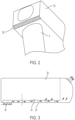
Figure 2 shows a front region of the nacelle (without rotor) to show the air inlet position; -
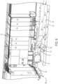
Figure 3 shows the nacelle with air conduit, showing the flow of cooling air; -
Figure 4 is a plan view of the nacelle from below showing the position of the conduit arrangement; -
Figure 5A is a sectional view across a lower region of the nacelle to show the bottom cover and internal panel; -
Figure 5B is a detail ofFigure 5A ; -
Figure 6 shows a part of the panel provided in a modular form; -
Figure 7 is a schematic section across the nacelle showing an embodiment further provided with cooling side panels; and -
Figure 8 is a cutaway view taken longitudinally along the nacelle along its mid-section to show air supply to converter cabinets. - As shown in
Figure 1 a wind turbine nacelle structure is shown which incorporates a cooling arrangement according to an embodiment of the present invention. - As is conventional, the wind turbine includes a
nacelle 2 which houses the main operative components of the turbine as further discussed below. The nacelle sits atop a tower 4 which extends from a ground mounted foundation (not shown). A rotor 6 comprises a number of blades 8 (typically three blades) which are mounted on acentral hub 10. Thehub 10 is connected at a forward end of main shaft which is supported on a main bearing. The main bearing housing is shown schematically by 12 in the figure. The main shaft extends into gearbox and generator collectively indicated 14, which may comprise separate components or as a combined structure. The gearbox serves to increase the rotational speed to an appropriate degree for turning generator, whilst the generator serves to convert the rotational energy into electrical energy, as is well known in the art. Arranged to the rear of the generator and laterally displaced relative to the nacelle centreline towards a sidewall of the nacelle, is the power converter contained within converter cabinets indicated 16.Electrical transformer 18 is arranged at the nacelle rear in a dedicated transformer enclosure. Thetransformer 18 increases the voltage of the generated electricity from about 690V to a medium voltage for connection to the grid via one or more further step up transformers. The operative components are supported on an internal load-bearing machine frame (not shown) which is connected to the tower by means of a yaw bearing (not shown). The position of the tower opening in the nacelle at which connection is made via the yaw bearing is indicated 19 inFigure 4 . The nacelle is provided with anexternal nacelle cover 20 which encloses the operative components shielding them from the environment. In one form this is generally box-like with bottom cover, roof, opposed side walls, and front and rear ends, these being formed by a number of interconnected panels of a light rigid material such as a composite material, glass-fibre reinforced plastic or the like which are carried directly or indirectly on the machine frame. In other forms the nacelle cover may be generally cylindrical or other shape. - The main operative components mentioned above all produce a degree of unwanted waste heat when in operation, the mechanical components such as the gearbox due to frictional forces, the generator as an electro-mechanical converter due to both mechanical friction and electrical losses, and the transformer due to electrical losses.
- As is conventional, certain of these components are cooled by means of cooling liquid which is circulated in a closed cooling circuit which passes through a heat exchanger (not illustrated). For example, the gearbox is cooled by means of an oil or water flow circuit in thermal communication with a heat exchanger which may be externally mounted on the nacelle, such as on the nacelle roof whereby heat can be exchanged with the external environment.
- Various heat-generating components are required to be air-cooled and are conventionally cooled by external air which is led over or through the component from dedicated inlets in the nacelle cover. In accordance with an embodiment of the invention, instead of providing dedicated internal ducting for cooling air as is conventional, the nacelle is arranged so that a portion of the
nacelle cover 20 itself provides part of the cooling air conduit-defining structure. As shown inFigure 1 an air conduit is defined between abottom cover 22 of thenacelle 20 and aninternal panel 24 which vertically overlies and extends parallel to thebottom cover 22, in essence forming a double-walled structure. As shown, thisinternal panel 24 extends over nearly all or at least the majority of thebottom cover 22 from aninlet 26 at the front region of the nacelle forward of the tower opening 19 as is shown inFigure 2 , passing around the opening 19 on both sides, extending towards the rear of the nacelle, such that theinternal panel 24 underlies the majority if not all of the main operative components needing air cooling. Theinternal panel 24 also extends laterally across almost the entire width of thebottom cover 22, as can be seen inFigures 4 and 5A . Thebottom cover 22 andinternal panel 24 thereby define together a conduit for supply of cooling air to operative components. Theair inlet 26 extends across a significant width of thebottom cover 24 in order to maximise the opening area and reduce the pressure drop as air is drawn in, and is covered by a grill or mesh to limit or prevent the ingress of rain, particles, insects or other foreign material or debris. Anadditional inlet region 28 may be provided to the rear of the yaw opening. - The conduit supplies cooling air to one or more operative components. As shown in
Figure 8 , air is supplied toconverter 16, theinternal panel 24 opening directly or indirectly via a short additional region of ducting 29 into the cooling air supply manifold of theconverter 16. Fans are provided in order to draw air into and along the conduit, at theinlet 26 and/or at positions along the length of the conduit and/or at the points at which air is drawn off the conduit. As can be seen inFigure 8 afan 30 is located at theconverter 16 between theducting 29 andconverter 16. Although not shown, air may exit the converter and nacelle via a dedicated outlet through a wall of the nacelle. Alternatively, it may be returned into the air conduit to mix with the fresh air or led into the transformer enclosure from where exits the nacelle. - To the rear of the air take off for the
converter 16, the conduit further directs air to thetransformer 18, opening directly into, or indirectly as illustrated via a short additional duct 35 into the transformer enclosure driven byfan 37. An air outlet 33 is provided at the nacelle rear, preferably at an upper region of the rear panel through which the heated air exits the transformer enclosure and nacelle and is exhausted to the external environment. - As an alternative, the internal panel may be of lesser lateral and/or longitudinal extent extending over a smaller region of the bottom cover.
- A particular benefit of arranging the air conduit in the very lowermost region of the nacelle is that this region represents dead space which is otherwise largely unoccupied by other components. Moreover, the inlet can be arranged at a region towards the front of the nacelle which is relatively uncrowded, being led in a space-occupying manner which is highly efficient below the crowded rear of the nacelle, from where it can supply cooling air to several heat-generating components as discussed above. The structure is further beneficial in supporting a modularisation of the nacelle in that the conduit structure can be provided to serve multiple nacelle layouts simply by making connection to the conduit at requisite locations according to component distribution and cooling need of a particular nacelle layout.
- The
internal panel 24 is preferably formed of a light rigid material in similar manner to thenacelle cover 20 for example of a moulded plastics or glass-fibre reinforced plastics. In view of the significant extent of the panel it is preferably formed of multiple sub-panel sections connected together. Thepanel 24 is preferably supported on thebottom cover 22 by any suitable fixings, screws, bolts or adhesive or the like. Alternatively, it might be separately supported directly or indirectly by the machine frame. The underside of theinternal panel 24 may be formed with depending walls or partitions to further contain the airflow for example to direct airflow to specific points at which connection to operative components is made. Sealing structures such as rubber seals or gaskets may be provided to ensure an air tight joint betweenbottom cover 22 andinternal panel 24. - In one form the
internal panel 24 may have a construction by which it can be used with a variety of different nacelle configurations. As shown inFigure 6 theinternal panel 24 is then provided on manufacture with a series of longitudinal andlateral partitions 32 crossing the underside of the internal cover, which prior to assembly can be selectively removed to define a flow path or paths in order to fit with the specific layout of operative components within the nacelle. In this way a single internal panel design can be manufactured and then adapted through removal of certain partitions to fit with the needed layout. To this end thepartitions 32 may be moulded with frangible joint regions to allow easy selective removal. This further supports modularisation of the nacelle. - As an alternative to arranging the circuit between a part of the nacelle cover and a separate panel, the nacelle cover itself may be formed with a double wall configuration, either as separate spaced panels joined together or even as a unitary moulding. In this case the outermost of the panels is formed with the air inlet and the inner is formed with connections to the respective heat generating components.
- In one embodiment, as shown in
Figures 5A , B andFigure 6 theinternal panel 24 is further provided with functionality as a liquid spillage tray. Theinternal panel 24 is shaped to define upwardly a shallow liquid-containing receptacle, having an upwardly extendingrim 34 so that liquid which might inadvertently leak from an operative component, such as lubricating or cooling oil or water or other cooling medium, may be constrained in order to be collected and removed during a service operation, and prevented from leaking outside the nacelle.Figure 7 shows schematically use of theinternal panel 24 as a spillage tray collecting liquid leaked from gearbox orgenerator 14. As shown inFigure 5B , at the interface between thebottom cover 22 andinternal panel 24 thebottom cover 22 may be formed with an internally protruding lip 36. This serves to form a seal betweenbottom cover 22 andinternal panel 24 so that any liquid which might drip down the interior of the nacelle cover for example down the walls is directed into the tray. Further, at its edge theinternal cover 24 may define outside the rim 34 ashallow channel 38 in the manner of a gutter to constrain and direct such liquid. This feature is particularly useful to collect condensation which flows down the inside of the walls, allowing it to be directed to a collection vessel or to a drain hole. - The above described embodiment utilises the space between
nacelle bottom cover 20 andinternal panel 24 as a cooling air conduit. As an alternative configuration (or even in addition) conduits may be defined between a side wall or walls of the nacelle cover and an internal side panel or panels which laterally overlie and extend parallel to the side wall or side walls. This configuration may be combined with the first embodiment described above; as shown inFigure 7 theside wall 40 is provided with aninternal side panel 42 defining therebetween a rearwardly extending conduit. At a forward end of the conduit there is provided an inlet region likewise covered in a grill or mesh to prevent ingress of unwanted material, the conduit extending along the length of the sidewall or side walls towards the rear of the nacelle. One or more internal ducts are connected to the conduit to direct cooling air into operative components such as the transformer and converter. - In a still further adaptation the conduit construction may be used to provide a degree of air cooling of components such as gearbox and generator which are liquid cooled; for example, the oil or water cooling circuits may employ heat exchangers which are then air cooled with air from the conduit. Whilst the air conduit may not supply all the cooling need for such components, it may contribute to such cooling.
- It will be appreciated that various modifications to the embodiments described above are possible and will occur to those skilled in the art without departing from the scope of the invention which is defined by the following claims.
Claims (16)
- A wind turbine comprising a nacelle which houses operative components which in use generate heat, the nacelle including an external nacelle cover (20) to form an enclosure, and provided with an internal panel (24) which overlies a bottom cover (22) of the external cover to define therewith a conduit which underlies heat generating components for directing external air to the heat generating operative components, characterised in that respective ducts (29,35) are connected between the internal panel and heat generating operative components to direct the cooling air thereto from the conduit.
- A wind turbine according to claim 1 wherein the internal panel (24) extends laterally across substantially the entire width of the bottom cover(22) .
- A wind turbine according to any preceding claim, wherein the external cover includes an air inlet (26) which opens into the conduit.
- A wind turbine according to claim 3 wherein the air inlet (26) is provided at a region forward of a tower opening.
- A wind turbine according to claim 4 wherein the internal panel extends from the region forward of the tower opening, around sides of the tower opening towards the rear of the nacelle.
- A wind turbine according to any preceding claim wherein the ducts (29,35) connect to air inlet manifolds of the heat generating operative components.
- A wind turbine according to any preceding claim wherein the heat generating operative components comprise one or more of a converter (16) and a transformer (18).
- A wind turbine according to any preceding claim, wherein the internal panel is formed on an underside which faces the external cover with partitions (32) which serve to direct the flow of cooling air.
- A wind turbine according to claim 8 wherein a plurality of partitions (32) are provided on the internal panel extending laterally and longitudinally, which partitions are selectively removable prior to assembly in order to define a desired flow path for a particular configuration of heat generating operative components.
- A wind turbine according to any preceding claim wherein one or more fans (30,37) are provided in the conduit or at connections between conduit and components to draw air into the conduit and force it to the one or more heat-generating operative components.
- A wind turbine according to any preceding claim wherein the internal panel is formed with an upstanding rim (34) to upwardly define a liquid collecting receptacle to collect any liquid leakage or spillage from liquid containing operative components.
- A wind turbine according to claim 11 wherein a number of receptacles may be defined by upstanding rims, the receptacles associated with individual components.
- A wind turbine according to claim 11 or 12 wherein the internal panel defines a channel region (38) at its lateral periphery to collect any liquid passing down the side walls of the nacelle cover.
- A method of cooling heat generating operative components in a wind turbine according to any preceding claim, the method comprising drawing air into the conduit from the exterior and directing it via the conduit and ducts (29,35) to the heat generating operative components.
- A method according to claim 14 further comprising directing air into the conduit at a forward region of the nacelle.
- A method according to claim 14 or 15 further comprising expelling air from the nacelle after passage over the heat generating components.
Applications Claiming Priority (2)
| Application Number | Priority Date | Filing Date | Title |
|---|---|---|---|
| DKPA201770952 | 2017-12-17 | ||
| PCT/DK2018/050366 WO2019114909A1 (en) | 2017-12-17 | 2018-12-14 | Wind turbine nacelle cooling |
Publications (3)
| Publication Number | Publication Date |
|---|---|
| EP3724494A1 EP3724494A1 (en) | 2020-10-21 |
| EP3724494B1 true EP3724494B1 (en) | 2024-07-10 |
| EP3724494C0 EP3724494C0 (en) | 2024-07-10 |
Family
ID=64948997
Family Applications (1)
| Application Number | Title | Priority Date | Filing Date |
|---|---|---|---|
| EP18829721.2A Active EP3724494B1 (en) | 2017-12-17 | 2018-12-14 | Wind turbine nacelle cooling |
Country Status (5)
| Country | Link |
|---|---|
| US (1) | US11493027B2 (en) |
| EP (1) | EP3724494B1 (en) |
| CN (1) | CN111727318B (en) |
| ES (1) | ES2983585T3 (en) |
| WO (1) | WO2019114909A1 (en) |
Families Citing this family (8)
| Publication number | Priority date | Publication date | Assignee | Title |
|---|---|---|---|---|
| ES2947310T3 (en) * | 2016-09-13 | 2023-08-04 | Vestas Wind Sys As | wind turbine nacelle cover |
| EP3372825A1 (en) * | 2017-03-07 | 2018-09-12 | Adwen GmbH | Nacelle having liquid retaining properties |
| WO2022063378A1 (en) * | 2020-09-24 | 2022-03-31 | Vestas Wind Systems A/S | Effective cooling of electric power converter |
| EP4015818B1 (en) * | 2020-12-18 | 2024-10-16 | Wobben Properties GmbH | Wind energy system |
| EP4083413B1 (en) * | 2021-04-28 | 2024-05-15 | General Electric Renovables España S.L. | Back-up power supply for wind turbines |
| CN116733694A (en) * | 2022-02-28 | 2023-09-12 | 金风科技股份有限公司 | Wind generating set |
| WO2025242304A1 (en) * | 2024-05-22 | 2025-11-27 | General Electric Renovables España S.L. | Wind turbine nacelle with liquid containment and associated method |
| CN118462512B (en) * | 2024-07-03 | 2025-01-17 | 江苏携之创科技有限公司 | An assembled wind turbine cabin cover capable of reducing noise |
Citations (1)
| Publication number | Priority date | Publication date | Assignee | Title |
|---|---|---|---|---|
| EP3477101A1 (en) * | 2017-10-25 | 2019-05-01 | Siemens Gamesa Renewable Energy A/S | Wind turbine with a nacelle including a water draining device |
Family Cites Families (10)
| Publication number | Priority date | Publication date | Assignee | Title |
|---|---|---|---|---|
| DE102004046700B4 (en) * | 2004-09-24 | 2006-08-17 | Aloys Wobben | Wind turbine with a generator cooling |
| US7427814B2 (en) * | 2006-03-22 | 2008-09-23 | General Electric Company | Wind turbine generators having wind assisted cooling systems and cooling methods |
| EP2255088B1 (en) * | 2008-03-20 | 2011-11-09 | Powerwind Gmbh | Wind turbine and method for operating a wind turbine |
| JP5123780B2 (en) | 2008-07-28 | 2013-01-23 | 三菱重工業株式会社 | Wind power generator |
| US8047774B2 (en) | 2008-09-11 | 2011-11-01 | General Electric Company | System for heating and cooling wind turbine components |
| US7789623B2 (en) * | 2008-10-30 | 2010-09-07 | General Electric Company | Protection arrangement for a wind turbine |
| CN102308082B (en) | 2009-02-05 | 2014-12-24 | 维斯塔斯风力系统有限公司 | Wind turbine with power electronics in the nacelle |
| US20130011272A1 (en) * | 2010-03-22 | 2013-01-10 | Vestas Wind Systems A/S | Nacelle for a wind turbine, the nacelle comprising side units |
| JP5463218B2 (en) * | 2010-06-30 | 2014-04-09 | 三菱重工業株式会社 | Wind power generator |
| US20150300323A1 (en) * | 2011-09-14 | 2015-10-22 | General Electric Company | System and method for collecting fluid leaking from a wind turbine component |
-
2018
- 2018-12-14 EP EP18829721.2A patent/EP3724494B1/en active Active
- 2018-12-14 US US16/954,365 patent/US11493027B2/en active Active
- 2018-12-14 CN CN201880088712.XA patent/CN111727318B/en active Active
- 2018-12-14 ES ES18829721T patent/ES2983585T3/en active Active
- 2018-12-14 WO PCT/DK2018/050366 patent/WO2019114909A1/en not_active Ceased
Patent Citations (1)
| Publication number | Priority date | Publication date | Assignee | Title |
|---|---|---|---|---|
| EP3477101A1 (en) * | 2017-10-25 | 2019-05-01 | Siemens Gamesa Renewable Energy A/S | Wind turbine with a nacelle including a water draining device |
Also Published As
| Publication number | Publication date |
|---|---|
| ES2983585T3 (en) | 2024-10-23 |
| CN111727318B (en) | 2023-10-13 |
| US11493027B2 (en) | 2022-11-08 |
| EP3724494A1 (en) | 2020-10-21 |
| US20210079898A1 (en) | 2021-03-18 |
| EP3724494C0 (en) | 2024-07-10 |
| CN111727318A (en) | 2020-09-29 |
| WO2019114909A1 (en) | 2019-06-20 |
Similar Documents
| Publication | Publication Date | Title |
|---|---|---|
| US11493027B2 (en) | Wind turbine nacelle cooling | |
| US9228566B2 (en) | Wind turbine comprising a cooling circuit | |
| US8029239B2 (en) | Rotor for a wind energy turbine and method for controlling the temperature inside a rotor hub | |
| EP2518315B1 (en) | Wind turbine power generating facilities | |
| EP2034181B1 (en) | Ventilation arrangement | |
| CN102301136B (en) | Wind turbine nacelle with cooler top | |
| CA2693766C (en) | Wind generator | |
| EP2573389B1 (en) | Cooling and climate control system and method for a wind turbine | |
| US20110204652A1 (en) | Wind power generator | |
| EP2546515B1 (en) | Wind turbine cooling arrangement | |
| KR20130040947A (en) | Wind turbine generator | |
| AU2011201772A1 (en) | Wind turbine generator | |
| US20100109326A1 (en) | Fan unit for wind power generator and wind power generator | |
| CN102753822A (en) | wind power plant | |
| CN102301134B (en) | Wind turbine nacelle with cooler on top | |
| JP4848398B2 (en) | Wind power generator | |
| KR20110050705A (en) | Wind power generator | |
| US20150361961A1 (en) | Ventilation arrangement | |
| JP6650318B2 (en) | Wind power generator | |
| CA2763082A1 (en) | Wind turbine featuring recirculation of a cooling stream | |
| JP6230424B2 (en) | Wind power generator | |
| KR101434440B1 (en) | Apparatus for nacelle air cooling using by heat exchanger | |
| US11585325B2 (en) | Method and system for cooling a wind turbine gearbox oil heat-exchanger | |
| EP2832992B1 (en) | Wind turbine comprising a cooling system | |
| EP2846038A1 (en) | Cooling system of a wind turbine |
Legal Events
| Date | Code | Title | Description |
|---|---|---|---|
| STAA | Information on the status of an ep patent application or granted ep patent |
Free format text: STATUS: UNKNOWN |
|
| STAA | Information on the status of an ep patent application or granted ep patent |
Free format text: STATUS: THE INTERNATIONAL PUBLICATION HAS BEEN MADE |
|
| PUAI | Public reference made under article 153(3) epc to a published international application that has entered the european phase |
Free format text: ORIGINAL CODE: 0009012 |
|
| STAA | Information on the status of an ep patent application or granted ep patent |
Free format text: STATUS: REQUEST FOR EXAMINATION WAS MADE |
|
| 17P | Request for examination filed |
Effective date: 20200706 |
|
| AK | Designated contracting states |
Kind code of ref document: A1 Designated state(s): AL AT BE BG CH CY CZ DE DK EE ES FI FR GB GR HR HU IE IS IT LI LT LU LV MC MK MT NL NO PL PT RO RS SE SI SK SM TR |
|
| AX | Request for extension of the european patent |
Extension state: BA ME |
|
| DAV | Request for validation of the european patent (deleted) | ||
| DAX | Request for extension of the european patent (deleted) | ||
| STAA | Information on the status of an ep patent application or granted ep patent |
Free format text: STATUS: EXAMINATION IS IN PROGRESS |
|
| 17Q | First examination report despatched |
Effective date: 20220718 |
|
| GRAP | Despatch of communication of intention to grant a patent |
Free format text: ORIGINAL CODE: EPIDOSNIGR1 |
|
| STAA | Information on the status of an ep patent application or granted ep patent |
Free format text: STATUS: GRANT OF PATENT IS INTENDED |
|
| INTG | Intention to grant announced |
Effective date: 20240129 |
|
| GRAS | Grant fee paid |
Free format text: ORIGINAL CODE: EPIDOSNIGR3 |
|
| GRAA | (expected) grant |
Free format text: ORIGINAL CODE: 0009210 |
|
| STAA | Information on the status of an ep patent application or granted ep patent |
Free format text: STATUS: THE PATENT HAS BEEN GRANTED |
|
| AK | Designated contracting states |
Kind code of ref document: B1 Designated state(s): AL AT BE BG CH CY CZ DE DK EE ES FI FR GB GR HR HU IE IS IT LI LT LU LV MC MK MT NL NO PL PT RO RS SE SI SK SM TR |
|
| REG | Reference to a national code |
Ref country code: CH Ref legal event code: EP |
|
| REG | Reference to a national code |
Ref country code: DE Ref legal event code: R096 Ref document number: 602018071658 Country of ref document: DE |
|
| U01 | Request for unitary effect filed |
Effective date: 20240725 |
|
| U07 | Unitary effect registered |
Designated state(s): AT BE BG DE DK EE FI FR IT LT LU LV MT NL PT SE SI Effective date: 20240808 |
|
| REG | Reference to a national code |
Ref country code: ES Ref legal event code: FG2A Ref document number: 2983585 Country of ref document: ES Kind code of ref document: T3 Effective date: 20241023 |
|
| PG25 | Lapsed in a contracting state [announced via postgrant information from national office to epo] |
Ref country code: NO Free format text: LAPSE BECAUSE OF FAILURE TO SUBMIT A TRANSLATION OF THE DESCRIPTION OR TO PAY THE FEE WITHIN THE PRESCRIBED TIME-LIMIT Effective date: 20241010 |
|
| PG25 | Lapsed in a contracting state [announced via postgrant information from national office to epo] |
Ref country code: GR Free format text: LAPSE BECAUSE OF FAILURE TO SUBMIT A TRANSLATION OF THE DESCRIPTION OR TO PAY THE FEE WITHIN THE PRESCRIBED TIME-LIMIT Effective date: 20241011 Ref country code: PL Free format text: LAPSE BECAUSE OF FAILURE TO SUBMIT A TRANSLATION OF THE DESCRIPTION OR TO PAY THE FEE WITHIN THE PRESCRIBED TIME-LIMIT Effective date: 20240710 |
|
| PG25 | Lapsed in a contracting state [announced via postgrant information from national office to epo] |
Ref country code: IS Free format text: LAPSE BECAUSE OF FAILURE TO SUBMIT A TRANSLATION OF THE DESCRIPTION OR TO PAY THE FEE WITHIN THE PRESCRIBED TIME-LIMIT Effective date: 20241110 |
|
| PG25 | Lapsed in a contracting state [announced via postgrant information from national office to epo] |
Ref country code: HR Free format text: LAPSE BECAUSE OF FAILURE TO SUBMIT A TRANSLATION OF THE DESCRIPTION OR TO PAY THE FEE WITHIN THE PRESCRIBED TIME-LIMIT Effective date: 20240710 |
|
| PG25 | Lapsed in a contracting state [announced via postgrant information from national office to epo] |
Ref country code: RS Free format text: LAPSE BECAUSE OF FAILURE TO SUBMIT A TRANSLATION OF THE DESCRIPTION OR TO PAY THE FEE WITHIN THE PRESCRIBED TIME-LIMIT Effective date: 20241010 |
|
| U20 | Renewal fee for the european patent with unitary effect paid |
Year of fee payment: 7 Effective date: 20241225 |
|
| PG25 | Lapsed in a contracting state [announced via postgrant information from national office to epo] |
Ref country code: RS Free format text: LAPSE BECAUSE OF FAILURE TO SUBMIT A TRANSLATION OF THE DESCRIPTION OR TO PAY THE FEE WITHIN THE PRESCRIBED TIME-LIMIT Effective date: 20241010 Ref country code: PL Free format text: LAPSE BECAUSE OF FAILURE TO SUBMIT A TRANSLATION OF THE DESCRIPTION OR TO PAY THE FEE WITHIN THE PRESCRIBED TIME-LIMIT Effective date: 20240710 Ref country code: NO Free format text: LAPSE BECAUSE OF FAILURE TO SUBMIT A TRANSLATION OF THE DESCRIPTION OR TO PAY THE FEE WITHIN THE PRESCRIBED TIME-LIMIT Effective date: 20241010 Ref country code: IS Free format text: LAPSE BECAUSE OF FAILURE TO SUBMIT A TRANSLATION OF THE DESCRIPTION OR TO PAY THE FEE WITHIN THE PRESCRIBED TIME-LIMIT Effective date: 20241110 Ref country code: HR Free format text: LAPSE BECAUSE OF FAILURE TO SUBMIT A TRANSLATION OF THE DESCRIPTION OR TO PAY THE FEE WITHIN THE PRESCRIBED TIME-LIMIT Effective date: 20240710 Ref country code: GR Free format text: LAPSE BECAUSE OF FAILURE TO SUBMIT A TRANSLATION OF THE DESCRIPTION OR TO PAY THE FEE WITHIN THE PRESCRIBED TIME-LIMIT Effective date: 20241011 |
|
| PG25 | Lapsed in a contracting state [announced via postgrant information from national office to epo] |
Ref country code: SM Free format text: LAPSE BECAUSE OF FAILURE TO SUBMIT A TRANSLATION OF THE DESCRIPTION OR TO PAY THE FEE WITHIN THE PRESCRIBED TIME-LIMIT Effective date: 20240710 |
|
| PG25 | Lapsed in a contracting state [announced via postgrant information from national office to epo] |
Ref country code: CZ Free format text: LAPSE BECAUSE OF FAILURE TO SUBMIT A TRANSLATION OF THE DESCRIPTION OR TO PAY THE FEE WITHIN THE PRESCRIBED TIME-LIMIT Effective date: 20240710 |
|
| PG25 | Lapsed in a contracting state [announced via postgrant information from national office to epo] |
Ref country code: SK Free format text: LAPSE BECAUSE OF FAILURE TO SUBMIT A TRANSLATION OF THE DESCRIPTION OR TO PAY THE FEE WITHIN THE PRESCRIBED TIME-LIMIT Effective date: 20240710 |
|
| PLBE | No opposition filed within time limit |
Free format text: ORIGINAL CODE: 0009261 |
|
| STAA | Information on the status of an ep patent application or granted ep patent |
Free format text: STATUS: NO OPPOSITION FILED WITHIN TIME LIMIT |
|
| 26N | No opposition filed |
Effective date: 20250411 |
|
| PG25 | Lapsed in a contracting state [announced via postgrant information from national office to epo] |
Ref country code: MC Free format text: LAPSE BECAUSE OF FAILURE TO SUBMIT A TRANSLATION OF THE DESCRIPTION OR TO PAY THE FEE WITHIN THE PRESCRIBED TIME-LIMIT Effective date: 20240710 |
|
| REG | Reference to a national code |
Ref country code: CH Ref legal event code: PL |
|
| PG25 | Lapsed in a contracting state [announced via postgrant information from national office to epo] |
Ref country code: CH Free format text: LAPSE BECAUSE OF NON-PAYMENT OF DUE FEES Effective date: 20241231 |
|
| PG25 | Lapsed in a contracting state [announced via postgrant information from national office to epo] |
Ref country code: IE Free format text: LAPSE BECAUSE OF NON-PAYMENT OF DUE FEES Effective date: 20241214 |
|
| PG25 | Lapsed in a contracting state [announced via postgrant information from national office to epo] |
Ref country code: RO Free format text: LAPSE BECAUSE OF FAILURE TO SUBMIT A TRANSLATION OF THE DESCRIPTION OR TO PAY THE FEE WITHIN THE PRESCRIBED TIME-LIMIT Effective date: 20240710 |
|
| PGFP | Annual fee paid to national office [announced via postgrant information from national office to epo] |
Ref country code: GB Payment date: 20251223 Year of fee payment: 8 |
|
| U20 | Renewal fee for the european patent with unitary effect paid |
Year of fee payment: 8 Effective date: 20251223 |
|
| PGFP | Annual fee paid to national office [announced via postgrant information from national office to epo] |
Ref country code: ES Payment date: 20260122 Year of fee payment: 8 |
|
| PG25 | Lapsed in a contracting state [announced via postgrant information from national office to epo] |
Ref country code: CY Free format text: LAPSE BECAUSE OF FAILURE TO SUBMIT A TRANSLATION OF THE DESCRIPTION OR TO PAY THE FEE WITHIN THE PRESCRIBED TIME-LIMIT Effective date: 20240710 |