EP3724027B1 - Illuminant for vehicle headlight with automatic beam mode selection - Google Patents
Illuminant for vehicle headlight with automatic beam mode selection Download PDFInfo
- Publication number
- EP3724027B1 EP3724027B1 EP18829213.0A EP18829213A EP3724027B1 EP 3724027 B1 EP3724027 B1 EP 3724027B1 EP 18829213 A EP18829213 A EP 18829213A EP 3724027 B1 EP3724027 B1 EP 3724027B1
- Authority
- EP
- European Patent Office
- Prior art keywords
- illuminant
- vehicle
- light
- light detector
- beam led
- Prior art date
- Legal status (The legal status is an assumption and is not a legal conclusion. Google has not performed a legal analysis and makes no representation as to the accuracy of the status listed.)
- Active
Links
Images




Classifications
-
- B—PERFORMING OPERATIONS; TRANSPORTING
- B60—VEHICLES IN GENERAL
- B60Q—ARRANGEMENT OF SIGNALLING OR LIGHTING DEVICES, THE MOUNTING OR SUPPORTING THEREOF OR CIRCUITS THEREFOR, FOR VEHICLES IN GENERAL
- B60Q1/00—Arrangement of optical signalling or lighting devices, the mounting or supporting thereof or circuits therefor
- B60Q1/02—Arrangement of optical signalling or lighting devices, the mounting or supporting thereof or circuits therefor the devices being primarily intended to illuminate the way ahead or to illuminate other areas of way or environments
- B60Q1/04—Arrangement of optical signalling or lighting devices, the mounting or supporting thereof or circuits therefor the devices being primarily intended to illuminate the way ahead or to illuminate other areas of way or environments the devices being headlights
- B60Q1/14—Arrangement of optical signalling or lighting devices, the mounting or supporting thereof or circuits therefor the devices being primarily intended to illuminate the way ahead or to illuminate other areas of way or environments the devices being headlights having dimming means
- B60Q1/1415—Dimming circuits
- B60Q1/1423—Automatic dimming circuits, i.e. switching between high beam and low beam due to change of ambient light or light level in road traffic
-
- B—PERFORMING OPERATIONS; TRANSPORTING
- B60—VEHICLES IN GENERAL
- B60Q—ARRANGEMENT OF SIGNALLING OR LIGHTING DEVICES, THE MOUNTING OR SUPPORTING THEREOF OR CIRCUITS THEREFOR, FOR VEHICLES IN GENERAL
- B60Q1/00—Arrangement of optical signalling or lighting devices, the mounting or supporting thereof or circuits therefor
- B60Q1/0017—Devices integrating an element dedicated to another function
- B60Q1/0023—Devices integrating an element dedicated to another function the element being a sensor, e.g. distance sensor, camera
-
- F—MECHANICAL ENGINEERING; LIGHTING; HEATING; WEAPONS; BLASTING
- F21—LIGHTING
- F21K—NON-ELECTRIC LIGHT SOURCES USING LUMINESCENCE; LIGHT SOURCES USING ELECTROCHEMILUMINESCENCE; LIGHT SOURCES USING CHARGES OF COMBUSTIBLE MATERIAL; LIGHT SOURCES USING SEMICONDUCTOR DEVICES AS LIGHT-GENERATING ELEMENTS; LIGHT SOURCES NOT OTHERWISE PROVIDED FOR
- F21K9/00—Light sources using semiconductor devices as light-generating elements, e.g. using light-emitting diodes [LED] or lasers
- F21K9/20—Light sources comprising attachment means
- F21K9/23—Retrofit light sources for lighting devices with a single fitting for each light source, e.g. for substitution of incandescent lamps with bayonet or threaded fittings
-
- F—MECHANICAL ENGINEERING; LIGHTING; HEATING; WEAPONS; BLASTING
- F21—LIGHTING
- F21S—NON-PORTABLE LIGHTING DEVICES; SYSTEMS THEREOF; VEHICLE LIGHTING DEVICES SPECIALLY ADAPTED FOR VEHICLE EXTERIORS
- F21S41/00—Illuminating devices specially adapted for vehicle exteriors, e.g. headlamps
- F21S41/10—Illuminating devices specially adapted for vehicle exteriors, e.g. headlamps characterised by the light source
- F21S41/14—Illuminating devices specially adapted for vehicle exteriors, e.g. headlamps characterised by the light source characterised by the type of light source
- F21S41/141—Light emitting diodes [LED]
-
- F—MECHANICAL ENGINEERING; LIGHTING; HEATING; WEAPONS; BLASTING
- F21—LIGHTING
- F21S—NON-PORTABLE LIGHTING DEVICES; SYSTEMS THEREOF; VEHICLE LIGHTING DEVICES SPECIALLY ADAPTED FOR VEHICLE EXTERIORS
- F21S41/00—Illuminating devices specially adapted for vehicle exteriors, e.g. headlamps
- F21S41/10—Illuminating devices specially adapted for vehicle exteriors, e.g. headlamps characterised by the light source
- F21S41/14—Illuminating devices specially adapted for vehicle exteriors, e.g. headlamps characterised by the light source characterised by the type of light source
- F21S41/141—Light emitting diodes [LED]
- F21S41/151—Light emitting diodes [LED] arranged in one or more lines
-
- F—MECHANICAL ENGINEERING; LIGHTING; HEATING; WEAPONS; BLASTING
- F21—LIGHTING
- F21S—NON-PORTABLE LIGHTING DEVICES; SYSTEMS THEREOF; VEHICLE LIGHTING DEVICES SPECIALLY ADAPTED FOR VEHICLE EXTERIORS
- F21S41/00—Illuminating devices specially adapted for vehicle exteriors, e.g. headlamps
- F21S41/10—Illuminating devices specially adapted for vehicle exteriors, e.g. headlamps characterised by the light source
- F21S41/19—Attachment of light sources or lamp holders
- F21S41/192—Details of lamp holders, terminals or connectors
-
- F—MECHANICAL ENGINEERING; LIGHTING; HEATING; WEAPONS; BLASTING
- F21—LIGHTING
- F21S—NON-PORTABLE LIGHTING DEVICES; SYSTEMS THEREOF; VEHICLE LIGHTING DEVICES SPECIALLY ADAPTED FOR VEHICLE EXTERIORS
- F21S41/00—Illuminating devices specially adapted for vehicle exteriors, e.g. headlamps
- F21S41/30—Illuminating devices specially adapted for vehicle exteriors, e.g. headlamps characterised by reflectors
- F21S41/32—Optical layout thereof
- F21S41/321—Optical layout thereof the reflector being a surface of revolution or a planar surface, e.g. truncated
-
- F—MECHANICAL ENGINEERING; LIGHTING; HEATING; WEAPONS; BLASTING
- F21—LIGHTING
- F21S—NON-PORTABLE LIGHTING DEVICES; SYSTEMS THEREOF; VEHICLE LIGHTING DEVICES SPECIALLY ADAPTED FOR VEHICLE EXTERIORS
- F21S41/00—Illuminating devices specially adapted for vehicle exteriors, e.g. headlamps
- F21S41/40—Illuminating devices specially adapted for vehicle exteriors, e.g. headlamps characterised by screens, non-reflecting members, light-shielding members or fixed shades
-
- B—PERFORMING OPERATIONS; TRANSPORTING
- B60—VEHICLES IN GENERAL
- B60Q—ARRANGEMENT OF SIGNALLING OR LIGHTING DEVICES, THE MOUNTING OR SUPPORTING THEREOF OR CIRCUITS THEREFOR, FOR VEHICLES IN GENERAL
- B60Q2300/00—Indexing codes for automatically adjustable headlamps or automatically dimmable headlamps
- B60Q2300/30—Indexing codes relating to the vehicle environment
- B60Q2300/31—Atmospheric conditions
- B60Q2300/312—Adverse weather
-
- B—PERFORMING OPERATIONS; TRANSPORTING
- B60—VEHICLES IN GENERAL
- B60Q—ARRANGEMENT OF SIGNALLING OR LIGHTING DEVICES, THE MOUNTING OR SUPPORTING THEREOF OR CIRCUITS THEREFOR, FOR VEHICLES IN GENERAL
- B60Q2300/00—Indexing codes for automatically adjustable headlamps or automatically dimmable headlamps
- B60Q2300/30—Indexing codes relating to the vehicle environment
- B60Q2300/31—Atmospheric conditions
- B60Q2300/314—Ambient light
-
- B—PERFORMING OPERATIONS; TRANSPORTING
- B60—VEHICLES IN GENERAL
- B60Q—ARRANGEMENT OF SIGNALLING OR LIGHTING DEVICES, THE MOUNTING OR SUPPORTING THEREOF OR CIRCUITS THEREFOR, FOR VEHICLES IN GENERAL
- B60Q2300/00—Indexing codes for automatically adjustable headlamps or automatically dimmable headlamps
- B60Q2300/40—Indexing codes relating to other road users or special conditions
- B60Q2300/41—Indexing codes relating to other road users or special conditions preceding vehicle
-
- B—PERFORMING OPERATIONS; TRANSPORTING
- B60—VEHICLES IN GENERAL
- B60Q—ARRANGEMENT OF SIGNALLING OR LIGHTING DEVICES, THE MOUNTING OR SUPPORTING THEREOF OR CIRCUITS THEREFOR, FOR VEHICLES IN GENERAL
- B60Q2300/00—Indexing codes for automatically adjustable headlamps or automatically dimmable headlamps
- B60Q2300/40—Indexing codes relating to other road users or special conditions
- B60Q2300/42—Indexing codes relating to other road users or special conditions oncoming vehicle
-
- F—MECHANICAL ENGINEERING; LIGHTING; HEATING; WEAPONS; BLASTING
- F21—LIGHTING
- F21Y—INDEXING SCHEME ASSOCIATED WITH SUBCLASSES F21K, F21L, F21S and F21V, RELATING TO THE FORM OR THE KIND OF THE LIGHT SOURCES OR OF THE COLOUR OF THE LIGHT EMITTED
- F21Y2115/00—Light-generating elements of semiconductor light sources
- F21Y2115/10—Light-emitting diodes [LED]
Definitions
- the invention relates to an illuminant for a vehicle headlight with automatic beam mode selection.
- EP0541491A1 discloses a retrofit set consisting of two adapters, an oncoming light sensor, and a controller which might be integrated with one of the adapters allowing to retrofit an older car with automatic switching between high- and low-beam by inserting the adapters into the current supplies of the headlamps and mounting the sensor at the cover glass or reflector of the headlight and cabling the controller with the adapters and the sensor.
- DE 102009000289A1 discloses a pulse-width modulated LED daytime running light whose intensity is controlled in dependence on the ambient light level wherein the ambient light level is measured by a photosensitive portion of an LED of the daytime running light.
- Each one of the documents KR 10-2016-0101380 A and WO2016008738A1 discloses a retrofit LED automotive headlamp.
- KR 10 2004 0099 194 A discloses a headlight bulb comprising a socket, a vehicle light sensor and a relay.
- an illuminant for a vehicle headlight comprises a carrier.
- One, two, three, four or more high-beam light emitting diodes (LEDs), one, two, three, four or more low-beam LEDs, and one, two, three, four or more vehicle light detectors are mounted on the carrier.
- the illuminant comprises an electrical driver, a mechanical interface for mounting the illuminant in a corresponding socket of the vehicle headlight in a detachable way, and an electrical connector for supplying electrical power to the electrical driver.
- the electrical connector may be any kind of plug contact like a H4 plug contact for conventional automotive headlights.
- the electrical driver may be integrated in the carrier or the mechanical interface or may be an external device connected by a wire arranged between the mechanical interface and the electrical connector.
- the electrical driver is arranged to receive vehicle light detection signals from the vehicle light detector(s).
- the electrical driver is arranged to determine vehicle light emitted, for example, by an approaching or preceding vehicle by means of the vehicle light detection signals.
- the electrical driver is arranged to provide a drive current to the high-beam LEDs or low-beam LEDs depending on the determined light.
- the illuminant is a substitute bulb or illuminant which can be used to replace, for example, conventional H4 or H7 headlight bulbs.
- the vehicle light detector or detectors may especially be used for high-beam switching in order to avoid glaring approaching or preceding vehicles. Furthermore, self-blinding may be avoided in case of fog.
- the high-beam LED or LEDs may be arranged to provide an illumination field.
- the illumination field defines the area on the road which is illuminated by means of the high-beam during driving the vehicle.
- the vehicle light detector may be arranged to provide a detection field.
- the detection field defines a solid angle from which vehicle light emitted by approaching or preceding traffic can be detected.
- the illumination field and the detection field at least partly overlap.
- the driver of a vehicle may control the illuminant by means of a vehicle control system in the following way: In order to keep the flashlight function of the high-beam operative, the following could be done:
- Automatic mode (automatically switching between high-beam and low-beam) is normally always active when low-beam powerline of car is active (normally high 12V). But can be switched on and off be special pulse-sequence, e.g. 3 short high-beam powerline high pulses. So, if the driver presses the high-beam function three times shortly in a sequence, automatic mode changes from ON to OFF or vice versa.
- the electrical driver may be arranged to switch off the high-beam LED(s) or low-beam LED(s) for a predefined time interval.
- the electrical driver may in this case be arranged to receive the vehicle light detection signals detected during the predefined time interval.
- the LEDs are switched off for a short moment. In this moment no light is emitted by the LEDs. Only light from outside can reach the LEDs and vehicle light detector.
- the vehicle light measurement is done. If the measured value is above certain levels, a microcontroller or controller of the electrical driver decides which beam-mode to select and which LEDs to switch on again, or keeping switched off. The measurement may, depending on the pulse pause length, be done 200 times per second.
- the light-off time is that short and frequent that a human eye cannot recognize the off-cycles. It looks flicker free.
- the on-time interval in which the LEDs are switched on may follow a regular or irregular, e.g. random, pattern. The irregular pattern may avoid coincidence of switching especially with approaching vehicles.
- the high-beam LED(s) or low-beam LED(s) may simultaneously be switched off in order to maximize sensitivity of vehicle light detection.
- At least one high-beam LED or low-beam LED may be arranged to act as vehicle light detector during the predefined time interval.
- the LED(s) can be used in a photo diode mode while switched off. It is therefore possible to use the same beam pattern for detection and light emission, resulting in a perfect match of illumination field and detection field.
- One or more low-beam LED may, for example, be further used in a low-beam mode (high-beam LEDs are switched off) to enable an adaptable daytime running light.
- one or more separate LEDs arranged on the carrier in an offset position with respect to a focus point of a reflector of the respective headlight may be used for the daytime running light.
- the other high-beam or low-beam LEDs may in this case be driven in a dimmed mode.
- the illuminant may alternatively or in addition comprise at least one vehicle light detector being arranged separate from the high-beam LEDs or low-beam LEDs.
- LEDs which are arranged to emit white light e.g. blue LEDs with a corresponding light converter
- the separate vehicle light detector(s) e.g. photodiodes, may therefore be used to detect the rear light emitted by a preceding vehicle.
- the photodiode or photodiodes may alternatively or in addition be arranged to detect white light emitted by a vehicle headlight emitted by an approaching vehicle.
- the illuminant is arranged to detect ambient light.
- the electrical driver is arranged to provide the drive current to the high-beam LED or the low-beam LED depending on the detected ambient light.
- the vehicle light detector may receive vehicle light and ambient light.
- the detected ambient light may be used to correct or adapt the signals provided by the vehicle light detector by means of the detected ambient light such that differentiation between ambient light sources and approaching or preceding traffic is improved.
- the ambient light may, for example, be detected by means of one or more low-beam LEDs during time intervals in which at least the corresponding low-beam LEDs are switched off.
- the electrical driver may alternatively or in addition be arranged to detect the ambient light based on a time series of vehicle light detection signals.
- the vehicle light detection signals may be detected by means of one or more low-beam LEDs or high-beam LEDs when the corresponding LEDs are switched off as discussed above.
- a number of vehicle light detection signals which are detected in subsequent time intervals may be used to determine an ambient light threshold value. Switching off, for example, the high-beam LEDs may be performed as soon as the vehicle light detector detects one or more vehicle light detection signals above the ambient light threshold value.
- the basic idea of this approach is that ambient light changes slower than vehicle light.
- a maximum ambient light threshold value in order to avoid that a preceding vehicle is no longer detected after a certain time interval, which, otherwise, might e.g. happen by increasing the ambient light threshold value step-by-step upon approaching the rear light of a preceding vehicle.
- the illuminant may alternatively or in addition comprise an ambient light detector mounted on the carrier.
- the ambient light detector is arranged such that, on detection of ambient light, the detection of vehicle light is suppressed. Any characteristic which can be used to differentiate between vehicle light and ambient light (direction, spectrum etc.) may be used to minimize detection of vehicle light by means of the separate ambient light detector or detectors (e.g. photodiodes).
- An exterior surface of the carrier may be arranged to absorb light.
- the ambient light detector may, for example, be positioned on the carrier such that reception of vehicle light by means of the ambient light detector is minimized when mounted in the reflector of the vehicle headlight.
- the position of the ambient light detector or detectors may be such that an ambient light detection field does essentially not overlap with the field from which vehicle light is received.
- a coating or special surface structure provided on top of the carrier may be used to avoid or at least reduce multiple reflections especially of vehicle light.
- the illuminant may alternatively or in addition comprise a vehicle light shield.
- the vehicle light shield is arranged to suppress detection of vehicle light by means of the ambient light detector when mounted in the reflector of the vehicle headlight.
- the vehicle light shield may be a kind of shielding which avoids that vehicle light directly impinges on or is reflected by the reflector to the ambient light detector.
- the vehicle light shield may be arranged to absorb vehicle light in order to avoid multiple reflections and therefore subsequent detection by means of the ambient light detector or detectors.
- the illuminant may alternatively or in addition comprise a vehicle light filter.
- the vehicle light filter is arranged to suppress detection of vehicle light by means of the ambient light detector when mounted in the reflector of the vehicle headlight.
- the vehicle light filter may be arranged to filter certain wavelength ranges which are specific for headlights or rear lights. Two, three or more of such ambient light detectors with vehicle light filters may be used in order to differentiate between different types of headlights or rear lights.
- the illuminant may be arranged to adapt light emission in accordance with light emission of a second illuminant.
- a vehicle like a car comprises two headlights. There is thus a risk that the first illuminant arranged in the left headlight disturbs a second illuminant arranged in the right headlight and vice versa.
- the illuminant may therefore be arranged to detect and identify light emitted by an illuminant coupled to the same vehicle. Detection may be provided via the electrical power supply, an extra cable connection between both units, or by means of optical detection.
- the first illuminant may in this configuration, for example, be arranged to be controlled by the second illuminant.
- the first illuminant may operate in a slave mode, wherein the second illuminant is operating in a master mode.
- the operating mode of the first and the second illuminant may be predefined.
- the first or the second illuminant may take over control or adapt light emission in accordance with light emission of the other illuminant.
- the electrical driver may, for example, be arranged to provide signals via the electrical connection to the power supply, i.e., use a kind of power line communication.
- an optical sensor e.g. one of the vehicle light detectors, may be used to detect the other illuminant and adapt light emission accordingly.
- the "connection" between both units can be used for fog detection.
- both sides When normally both sides are switched off to detect vehicle light, one side keeps being switched on every x-th cycle, e.g. once in 10.000 cycles.
- the unit still switched off compares the ambient light value when the other unit is switched on with the last measurement when both units were switched off. If the light difference is above a certain level such is interpreted as fog and the high-beam is switched off for both sides.
- Fig. 1 shows a principal sketch of a first embodiment of an illuminant 100 for a vehicle headlight.
- the illuminant 100 comprises an electrical connector 114 which is mechanically coupled by means of mechanical interface 112 to a carrier 110.
- the electrical connector 114 is arranged to be mounted in a corresponding socket and comprises electrical connectors which are arranged to supply electrical power to an electrical driver 115 which is integrated in the carrier 110.
- Three high-beam LEDs 101 and three low-beam LEDs 103 are mounted on the carrier 110.
- a low-beam aperture 105 mounted on the carrier 110 is used to define a cutoff for the low-beam.
- the electrical driver 115 is electrically connected to the high-beam LEDs 101 and low-beam LEDs 103.
- the electrical driver 115 is arranged to drive the high-beam LEDs 101 and low-beam LEDs 103 in accordance with a corresponding switching scheme.
- One of the high-beam LEDs 101 is arranged to provide vehicle light detection signals during time intervals in which the high-beam LED 101 is switched off.
- Fig. 2 showing a principal sketch of a cross-section of the relevant part of the first embodiment of the illuminant 100 mounted in a reflector 130 of the headlight.
- the high-beam LED 101 is arranged to emit emitted light 152 in an illumination field in a first time period and to receive vehicle light 154 from a detection field in a second time period.
- the illumination field and detection field coincide in this embodiment.
- Fig. 3 shows the corresponding switching scheme for switching the high-beam LEDs 101 and low-beam LEDs 103.
- the x-axis shows the time 203 and the y-axis shows the drive current 201 provided by the electrical driver 115.
- the high-beam LEDs 101 and the low-beam LEDs 103 are simultaneously switched on at drive current 211 and switched off at drive current 213.
- the high-beam and low-beam LEDs 101, 103 are periodically switched off with a constant time interval.
- a first illuminant 100 may be used in the right headlight of a vehicle.
- the LED 101 of the illuminant 100 of the right headlight which is arranged to provide vehicle light detection signals may be arranged to detect vehicle light emitted by the left headlight of the vehicle.
- the first illuminant 100 of the right headlight may be arranged to adapt illumination in accordance with the detected light emitted by the left headlight, thus might e.g. synchronize their mutual switching patterns.
- the first illuminant 100 of the right headlight may be further arranged to provide a signal to a second illuminant 100 of the left headlight indicating that the first illuminant 100 of the right headlight is operating in a slave mode.
- the second illuminant 100 of the left headlight would in this case automatically operate in a master mode.
- the signal indicating that the first illuminant 100 of the right headlight is operating in a slave mode may be provided by means of a defined light sequence or an electrical signal which may be submitted via the power line such that the electrical driver 115 of the left headlight can detect the electrical signal.
- the first illuminant 100 of the right headlight may alternatively provide a signal that the first illuminant 100 of the right headlight is operating in a master mode.
- Operation of the illuminant 100 in the master or slave mode may be predefined e.g. in the way that a pair of illuminants 100 consists of a predefined master and a predefined slave, or may be adaptive as described above.
- Fig. 4 shows a principal sketch of a second embodiment of an illuminant 100 for a vehicle headlight.
- the configuration of the illuminant 100 is for illustration purposes similar to the first embodiment discussed with respect to Fig. 1 .
- the illuminant 100 comprises two additional vehicle light detectors 106 which are arranged near to the high-beam LEDs 101 such that the illumination field of the high-beam LEDs 101 and the detection field of the vehicle light detectors 106 overlap.
- the vehicle light detectors 106 are sensitive in the complete visible wavelength range in order to detect headlights of approaching vehicles and rear lights of preceding vehicles.
- the electrical driver 115 is in this embodiment an external device which is arranged between the mechanical interface 112 and the electrical connector 114 and connected to both of them with a cable.
- the electrical driver 115 is arranged to determine an ambient light threshold based on a time series of subsequent measurements performed by means of the vehicle light detectors 106.
- the measurements are preferably performed in short time intervals in which the high-beam LEDs 101 and low-beam LEDs 103 are switched off.
- the switching interval may e.g. be arranged in a random pattern.
- the electrical driver 115 may be further arranged to limit the ambient light threshold in order to avoid, for example, that the ambient light threshold takes into account light received from a preceding vehicle.
- the electrical driver 115 may be further arranged to ignore measurement signals provided by the vehicle light detectors 106 changing at a rate beyond a predefined threshold such that measurement signals caused by, for example, an approaching vehicle are ignored with respect to determination of the ambient light threshold.
- the electrical driver 115 may alternatively or in addition be arranged to ignore measurement signals above a threshold such that measurement signals caused by a rear light or head light are ignored with respect to the determination of the ambient light threshold.
- one or more of the high-beam LEDs 101 are used as additional vehicle light detectors.
- One or more of the low-beam LEDs 103 may optionally be used as ambient light detector in time intervals in which the low-beam LEDs 103 are switched off.
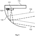
- Fig. 5 shows a principal sketch of a cross-section of the relevant part of the second embodiment of the illuminant 100 mounted in a reflector 130 of a headlight.
- the detection field of the vehicle light detector 106 overlaps with the illumination field of the high-beam LED 101. This is demonstrated by means of the emitted light 152 emitted by the high-beam LEDs 101 and the vehicle light 154 received by the vehicle light detector 106.
- Fig. 5 ignores the fact that the high-beam LEDs 101 are preferably switched of during detection of vehicle light 154.
- Fig. 6 shows a principal sketch of a third embodiment of an illuminant 100 for a vehicle headlight.
- the configuration is again very similar as discussed with respect to Fig. 1 .
- One or more of the high-beam LEDs 101 or low-beam LEDs 103 are used as vehicle light detectors as discussed above.
- An additional ambient light detector 107 is positioned at the end of the carrier 110. The position is selected such that essentially only ambient light 156 is received by the ambient light detector when mounted in a reflector 130 as shown in Fig. 7 .
- Fig. 7 shows a principal sketch of a cross-section of the relevant part of the third embodiment of the illuminant 100 mounted in a reflector 130 of the headlight.
- the position of the ambient light detector 107 may be adapted to the type of reflector 130 of the vehicle headlight.
- Fig. 8 shows a principal sketch of a cross-section of the relevant part of a fourth embodiment of the illuminant 100 mounted in a reflector 130 of a headlight.
- the illuminant 100 comprises in this case a separate vehicle light detector 106 as discussed with respect to Fig. 4 and an ambient light detector 107.
- the illuminant 100 further comprises a vehicle light shield 109 which is arranged to shield and absorb vehicle light 154 such that essentially no vehicle light 154 is detected by the ambient light detector 107.
- the carrier 110 is further covered with a light absorbing coating in order to avoid or at least reduce multiple reflections of vehicle light 154.
- Fig. 9 shows a principal sketch of a cross-section of the relevant part of a fifth embodiment of the illuminant 100 mounted in a reflector 130 of a headlight.
- the configuration is very similar as discussed with respect to Fig. 8 .
- the vehicle light shield 109 is replaced by a vehicle light filter 108 which is arranged to absorb light within a predefined wavelength range which is predominantly emitted by vehicle headlights or vehicle rear lights.
- the illuminant 100 may comprise two, three, four or more ambient light detectors 107 with different types of vehicle light filters 108 in accordance with different types of headlights or rear lights and the corresponding emission spectrum.
- the described measures to determine ambient light 156 may be combined in any suitable way in order to determine a reliable switching threshold for switching off or on the high-beam LEDs 101 or low-beam LEDs 103 in order to provide a suitable illumination mode.
Landscapes
- Engineering & Computer Science (AREA)
- General Engineering & Computer Science (AREA)
- Mechanical Engineering (AREA)
- Physics & Mathematics (AREA)
- Microelectronics & Electronic Packaging (AREA)
- Optics & Photonics (AREA)
- Lighting Device Outwards From Vehicle And Optical Signal (AREA)
- Arrangement Of Elements, Cooling, Sealing, Or The Like Of Lighting Devices (AREA)
Description
- The invention relates to an illuminant for a vehicle headlight with automatic beam mode selection.
- In today's cars, cameras and image data processing are used to automatically decide if high-beam, low-beam, or daytime running light etc. are to be used. The available solutions are cost intensive. Furthermore, it is not that easily possible to upgrade light systems of older cars.
-
EP0541491A1 discloses a retrofit set consisting of two adapters, an oncoming light sensor, and a controller which might be integrated with one of the adapters allowing to retrofit an older car with automatic switching between high- and low-beam by inserting the adapters into the current supplies of the headlamps and mounting the sensor at the cover glass or reflector of the headlight and cabling the controller with the adapters and the sensor. -
DE 102009000289A1 discloses a pulse-width modulated LED daytime running light whose intensity is controlled in dependence on the ambient light level wherein the ambient light level is measured by a photosensitive portion of an LED of the daytime running light. - Each one of the documents
KR 10-2016-0101380 A WO2016008738A1 discloses a retrofit LED automotive headlamp. -
KR 10 2004 0099 194 A - It is an object of the present invention to provide an illuminant for an automotive headlight with automatic beam mode selection.
- According to a first aspect an illuminant for a vehicle headlight according to claim 1 is provided. The illuminant comprises a carrier. One, two, three, four or more high-beam light emitting diodes (LEDs), one, two, three, four or more low-beam LEDs, and one, two, three, four or more vehicle light detectors are mounted on the carrier. The illuminant comprises an electrical driver, a mechanical interface for mounting the illuminant in a corresponding socket of the vehicle headlight in a detachable way, and an electrical connector for supplying electrical power to the electrical driver. The electrical connector may be any kind of plug contact like a H4 plug contact for conventional automotive headlights. The electrical driver may be integrated in the carrier or the mechanical interface or may be an external device connected by a wire arranged between the mechanical interface and the electrical connector. The electrical driver is arranged to receive vehicle light detection signals from the vehicle light detector(s). The electrical driver is arranged to determine vehicle light emitted, for example, by an approaching or preceding vehicle by means of the vehicle light detection signals. The electrical driver is arranged to provide a drive current to the high-beam LEDs or low-beam LEDs depending on the determined light.
- The illuminant is a substitute bulb or illuminant which can be used to replace, for example, conventional H4 or H7 headlight bulbs. The vehicle light detector or detectors may especially be used for high-beam switching in order to avoid glaring approaching or preceding vehicles. Furthermore, self-blinding may be avoided in case of fog.
- The high-beam LED or LEDs may be arranged to provide an illumination field. The illumination field defines the area on the road which is illuminated by means of the high-beam during driving the vehicle. The vehicle light detector may be arranged to provide a detection field. The detection field defines a solid angle from which vehicle light emitted by approaching or preceding traffic can be detected. The illumination field and the detection field at least partly overlap.
- The driver of a vehicle may control the illuminant by means of a vehicle control system in the following way:
In order to keep the flashlight function of the high-beam operative, the following could be done: - Low-beam powerline from car electric powers low-beam and high-beam of lighting unit comprising the illuminant.
- If high-beam powerline of car changes state (normally from 0V to 12V), high-beam LEDs are switched on.
- Automatic mode (automatically switching between high-beam and low-beam) is normally always active when low-beam powerline of car is active (normally high 12V). But can be switched on and off be special pulse-sequence, e.g. 3 short high-beam powerline high pulses. So, if the driver presses the high-beam function three times shortly in a sequence, automatic mode changes from ON to OFF or vice versa.
- The electrical driver may be arranged to switch off the high-beam LED(s) or low-beam LED(s) for a predefined time interval. The electrical driver may in this case be arranged to receive the vehicle light detection signals detected during the predefined time interval. The LEDs are switched off for a short moment. In this moment no light is emitted by the LEDs. Only light from outside can reach the LEDs and vehicle light detector. Within this pulse-pause, the vehicle light measurement is done. If the measured value is above certain levels, a microcontroller or controller of the electrical driver decides which beam-mode to select and which LEDs to switch on again, or keeping switched off. The measurement may, depending on the pulse pause length, be done 200 times per second. The light-off time is that short and frequent that a human eye cannot recognize the off-cycles. It looks flicker free. The on-time interval in which the LEDs are switched on may follow a regular or irregular, e.g. random, pattern. The irregular pattern may avoid coincidence of switching especially with approaching vehicles. The high-beam LED(s) or low-beam LED(s) may simultaneously be switched off in order to maximize sensitivity of vehicle light detection.
- At least one high-beam LED or low-beam LED may be arranged to act as vehicle light detector during the predefined time interval. The LED(s) can be used in a photo diode mode while switched off. It is therefore possible to use the same beam pattern for detection and light emission, resulting in a perfect match of illumination field and detection field. One or more low-beam LED may, for example, be further used in a low-beam mode (high-beam LEDs are switched off) to enable an adaptable daytime running light. Furthermore, one or more separate LEDs arranged on the carrier in an offset position with respect to a focus point of a reflector of the respective headlight may be used for the daytime running light. The other high-beam or low-beam LEDs may in this case be driven in a dimmed mode.
- The illuminant may alternatively or in addition comprise at least one vehicle light detector being arranged separate from the high-beam LEDs or low-beam LEDs. LEDs which are arranged to emit white light (e.g. blue LEDs with a corresponding light converter) may not be able to detect red light emitted by a rear light. The separate vehicle light detector(s), e.g. photodiodes, may therefore be used to detect the rear light emitted by a preceding vehicle. The photodiode or photodiodes may alternatively or in addition be arranged to detect white light emitted by a vehicle headlight emitted by an approaching vehicle.
- According to the invention, the illuminant is arranged to detect ambient light. The electrical driver is arranged to provide the drive current to the high-beam LED or the low-beam LED depending on the detected ambient light. The vehicle light detector may receive vehicle light and ambient light. The detected ambient light may be used to correct or adapt the signals provided by the vehicle light detector by means of the detected ambient light such that differentiation between ambient light sources and approaching or preceding traffic is improved. The ambient light may, for example, be detected by means of one or more low-beam LEDs during time intervals in which at least the corresponding low-beam LEDs are switched off.
- The electrical driver may alternatively or in addition be arranged to detect the ambient light based on a time series of vehicle light detection signals. The vehicle light detection signals may be detected by means of one or more low-beam LEDs or high-beam LEDs when the corresponding LEDs are switched off as discussed above. A number of vehicle light detection signals which are detected in subsequent time intervals may be used to determine an ambient light threshold value. Switching off, for example, the high-beam LEDs may be performed as soon as the vehicle light detector detects one or more vehicle light detection signals above the ambient light threshold value. The basic idea of this approach is that ambient light changes slower than vehicle light. Furthermore, there may be a maximum ambient light threshold value in order to avoid that a preceding vehicle is no longer detected after a certain time interval, which, otherwise, might e.g. happen by increasing the ambient light threshold value step-by-step upon approaching the rear light of a preceding vehicle.
- The illuminant may alternatively or in addition comprise an ambient light detector mounted on the carrier. The ambient light detector is arranged such that, on detection of ambient light, the detection of vehicle light is suppressed. Any characteristic which can be used to differentiate between vehicle light and ambient light (direction, spectrum etc.) may be used to minimize detection of vehicle light by means of the separate ambient light detector or detectors (e.g. photodiodes). An exterior surface of the carrier may be arranged to absorb light.
- The ambient light detector may, for example, be positioned on the carrier such that reception of vehicle light by means of the ambient light detector is minimized when mounted in the reflector of the vehicle headlight. The position of the ambient light detector or detectors may be such that an ambient light detection field does essentially not overlap with the field from which vehicle light is received. A coating or special surface structure provided on top of the carrier may be used to avoid or at least reduce multiple reflections especially of vehicle light.
- The illuminant may alternatively or in addition comprise a vehicle light shield. The vehicle light shield is arranged to suppress detection of vehicle light by means of the ambient light detector when mounted in the reflector of the vehicle headlight. The vehicle light shield may be a kind of shielding which avoids that vehicle light directly impinges on or is reflected by the reflector to the ambient light detector. The vehicle light shield may be arranged to absorb vehicle light in order to avoid multiple reflections and therefore subsequent detection by means of the ambient light detector or detectors.
- The illuminant may alternatively or in addition comprise a vehicle light filter. The vehicle light filter is arranged to suppress detection of vehicle light by means of the ambient light detector when mounted in the reflector of the vehicle headlight. The vehicle light filter may be arranged to filter certain wavelength ranges which are specific for headlights or rear lights. Two, three or more of such ambient light detectors with vehicle light filters may be used in order to differentiate between different types of headlights or rear lights.
- The illuminant may be arranged to adapt light emission in accordance with light emission of a second illuminant. A vehicle like a car comprises two headlights. There is thus a risk that the first illuminant arranged in the left headlight disturbs a second illuminant arranged in the right headlight and vice versa. The illuminant may therefore be arranged to detect and identify light emitted by an illuminant coupled to the same vehicle. Detection may be provided via the electrical power supply, an extra cable connection between both units, or by means of optical detection. The first illuminant may in this configuration, for example, be arranged to be controlled by the second illuminant. The first illuminant may operate in a slave mode, wherein the second illuminant is operating in a master mode. The operating mode of the first and the second illuminant may be predefined. Alternatively, the first or the second illuminant may take over control or adapt light emission in accordance with light emission of the other illuminant. The electrical driver may, for example, be arranged to provide signals via the electrical connection to the power supply, i.e., use a kind of power line communication. Alternatively or in addition, an optical sensor, e.g. one of the vehicle light detectors, may be used to detect the other illuminant and adapt light emission accordingly.
- The "connection" between both units can be used for fog detection. When normally both sides are switched off to detect vehicle light, one side keeps being switched on every x-th cycle, e.g. once in 10.000 cycles. The unit still switched off compares the ambient light value when the other unit is switched on with the last measurement when both units were switched off. If the light difference is above a certain level such is interpreted as fog and the high-beam is switched off for both sides.
- These and other aspects of the invention will be apparent from and elucidated with reference to the embodiments described hereinafter.
- The invention will now be described, by way of example, based on embodiments with reference to the accompanying drawings.
- In the drawings:
- Fig. 1
- shows a principal sketch of a first embodiment of an illuminant for a vehicle headlight.
- Fig. 2
- shows a principal sketch of a cross-section of the relevant part of the first embodiment of the illuminant mounted in a reflector of the headlight.
- Fig. 3
- shows a switching scheme for switching the high-beam LEDs or the low-beam LEDs.
- Fig. 4
- shows a principal sketch of a second embodiment of an illuminant for a vehicle headlight.
- Fig. 5
- shows a principal sketch of a cross-section of the relevant part of the second embodiment of the illuminant mounted in a reflector of the headlight.
- Fig. 6
- shows a principal sketch of a third embodiment of an illuminant for a vehicle headlight.
- Fig. 7
- shows a principal sketch of a cross-section of the relevant part of the third embodiment of the illuminant mounted in a reflector of the headlight.
- Fig. 8
- shows a principal sketch of a cross-section of the relevant part of a fourth embodiment of the illuminant mounted in a reflector of the headlight.
- Fig. 9
- shows a principal sketch of a cross-section of the relevant part of a fifth embodiment of the illuminant mounted in a reflector of the headlight.
- In the Figures, like numbers refer to like objects throughout. Objects in the Figures are not necessarily drawn to scale.
- Various embodiments of the invention will now be described by means of the Figures.
-
Fig. 1 shows a principal sketch of a first embodiment of anilluminant 100 for a vehicle headlight. Theilluminant 100 comprises anelectrical connector 114 which is mechanically coupled by means ofmechanical interface 112 to acarrier 110. Theelectrical connector 114 is arranged to be mounted in a corresponding socket and comprises electrical connectors which are arranged to supply electrical power to anelectrical driver 115 which is integrated in thecarrier 110. Three high-beam LEDs 101 and three low-beam LEDs 103 are mounted on thecarrier 110. A low-beam aperture 105 mounted on thecarrier 110 is used to define a cutoff for the low-beam. Theelectrical driver 115 is electrically connected to the high-beam LEDs 101 and low-beam LEDs 103. Theelectrical driver 115 is arranged to drive the high-beam LEDs 101 and low-beam LEDs 103 in accordance with a corresponding switching scheme. One of the high-beam LEDs 101 is arranged to provide vehicle light detection signals during time intervals in which the high-beam LED 101 is switched off. - The principle is shown in
Fig. 2 showing a principal sketch of a cross-section of the relevant part of the first embodiment of theilluminant 100 mounted in areflector 130 of the headlight. The high-beam LED 101 is arranged to emit emitted light 152 in an illumination field in a first time period and to receive vehicle light 154 from a detection field in a second time period. The illumination field and detection field coincide in this embodiment. -
Fig. 3 shows the corresponding switching scheme for switching the high-beam LEDs 101 and low-beam LEDs 103. The x-axis shows thetime 203 and the y-axis shows the drive current 201 provided by theelectrical driver 115. The high-beam LEDs 101 and the low-beam LEDs 103 are simultaneously switched on at drive current 211 and switched off at drive current 213. The high-beam and low-beam LEDs first illuminant 100 may be used in the right headlight of a vehicle. TheLED 101 of theilluminant 100 of the right headlight which is arranged to provide vehicle light detection signals may be arranged to detect vehicle light emitted by the left headlight of the vehicle. Thefirst illuminant 100 of the right headlight may be arranged to adapt illumination in accordance with the detected light emitted by the left headlight, thus might e.g. synchronize their mutual switching patterns. Thefirst illuminant 100 of the right headlight may be further arranged to provide a signal to asecond illuminant 100 of the left headlight indicating that thefirst illuminant 100 of the right headlight is operating in a slave mode. Thesecond illuminant 100 of the left headlight would in this case automatically operate in a master mode. The signal indicating that thefirst illuminant 100 of the right headlight is operating in a slave mode may be provided by means of a defined light sequence or an electrical signal which may be submitted via the power line such that theelectrical driver 115 of the left headlight can detect the electrical signal. Thefirst illuminant 100 of the right headlight may alternatively provide a signal that thefirst illuminant 100 of the right headlight is operating in a master mode. - Operation of the
illuminant 100 in the master or slave mode may be predefined e.g. in the way that a pair ofilluminants 100 consists of a predefined master and a predefined slave, or may be adaptive as described above. -
Fig. 4 shows a principal sketch of a second embodiment of anilluminant 100 for a vehicle headlight. The configuration of theilluminant 100 is for illustration purposes similar to the first embodiment discussed with respect toFig. 1 . Theilluminant 100 comprises two additionalvehicle light detectors 106 which are arranged near to the high-beam LEDs 101 such that the illumination field of the high-beam LEDs 101 and the detection field of thevehicle light detectors 106 overlap. Thevehicle light detectors 106 are sensitive in the complete visible wavelength range in order to detect headlights of approaching vehicles and rear lights of preceding vehicles. Theelectrical driver 115 is in this embodiment an external device which is arranged between themechanical interface 112 and theelectrical connector 114 and connected to both of them with a cable. - The
electrical driver 115 is arranged to determine an ambient light threshold based on a time series of subsequent measurements performed by means of thevehicle light detectors 106. The measurements are preferably performed in short time intervals in which the high-beam LEDs 101 and low-beam LEDs 103 are switched off. The switching interval may e.g. be arranged in a random pattern. Theelectrical driver 115 may be further arranged to limit the ambient light threshold in order to avoid, for example, that the ambient light threshold takes into account light received from a preceding vehicle. Theelectrical driver 115 may be further arranged to ignore measurement signals provided by thevehicle light detectors 106 changing at a rate beyond a predefined threshold such that measurement signals caused by, for example, an approaching vehicle are ignored with respect to determination of the ambient light threshold. Theelectrical driver 115 may alternatively or in addition be arranged to ignore measurement signals above a threshold such that measurement signals caused by a rear light or head light are ignored with respect to the determination of the ambient light threshold. Optionally one or more of the high-beam LEDs 101 are used as additional vehicle light detectors. One or more of the low-beam LEDs 103 may optionally be used as ambient light detector in time intervals in which the low-beam LEDs 103 are switched off. -
Fig. 5 shows a principal sketch of a cross-section of the relevant part of the second embodiment of theilluminant 100 mounted in areflector 130 of a headlight. The detection field of thevehicle light detector 106 overlaps with the illumination field of the high-beam LED 101. This is demonstrated by means of the emitted light 152 emitted by the high-beam LEDs 101 and thevehicle light 154 received by thevehicle light detector 106.Fig. 5 ignores the fact that the high-beam LEDs 101 are preferably switched of during detection ofvehicle light 154. -
Fig. 6 shows a principal sketch of a third embodiment of anilluminant 100 for a vehicle headlight. The configuration is again very similar as discussed with respect toFig. 1 . One or more of the high-beam LEDs 101 or low-beam LEDs 103 are used as vehicle light detectors as discussed above. An additional ambientlight detector 107 is positioned at the end of thecarrier 110. The position is selected such that essentially onlyambient light 156 is received by the ambient light detector when mounted in areflector 130 as shown inFig. 7 . -
Fig. 7 shows a principal sketch of a cross-section of the relevant part of the third embodiment of theilluminant 100 mounted in areflector 130 of the headlight. The position of the ambientlight detector 107 may be adapted to the type ofreflector 130 of the vehicle headlight. -
Fig. 8 shows a principal sketch of a cross-section of the relevant part of a fourth embodiment of theilluminant 100 mounted in areflector 130 of a headlight. Theilluminant 100 comprises in this case a separatevehicle light detector 106 as discussed with respect toFig. 4 and an ambientlight detector 107. Theilluminant 100 further comprises avehicle light shield 109 which is arranged to shield and absorb vehicle light 154 such that essentially novehicle light 154 is detected by the ambientlight detector 107. Thecarrier 110 is further covered with a light absorbing coating in order to avoid or at least reduce multiple reflections ofvehicle light 154. -
Fig. 9 shows a principal sketch of a cross-section of the relevant part of a fifth embodiment of theilluminant 100 mounted in areflector 130 of a headlight. The configuration is very similar as discussed with respect toFig. 8 . Thevehicle light shield 109 is replaced by a vehiclelight filter 108 which is arranged to absorb light within a predefined wavelength range which is predominantly emitted by vehicle headlights or vehicle rear lights. Theilluminant 100 may comprise two, three, four or more ambientlight detectors 107 with different types of vehicle light filters 108 in accordance with different types of headlights or rear lights and the corresponding emission spectrum. - The described measures to determine
ambient light 156 may be combined in any suitable way in order to determine a reliable switching threshold for switching off or on the high-beam LEDs 101 or low-beam LEDs 103 in order to provide a suitable illumination mode. - While the invention has been illustrated and described in detail in the drawings and the foregoing description, such illustration and description are to be considered illustrative or exemplary and not restrictive.
- Variations to the disclosed embodiments can be understood and effected by those skilled in the art, from a study of the drawings, the disclosure and the appended claims. In the claims, the word "comprising" does not exclude other elements or steps, and the indefinite article "a" or "an" does not exclude a plurality of elements or steps. The mere fact that certain measures are recited in mutually different dependent claims does not indicate that a combination of these measures cannot be used to advantage.
- Any reference signs in the claims should not be construed as limiting the scope thereof.
-
- 100
- illuminant for automotive headlight
- 101
- high-beam LED
- 103
- low-beam LED
- 105
- low-beam aperture
- 106
- vehicle light detector
- 107
- ambient light detector
- 108
- vehicle light filter
- 109
- vehicle light shield
- 110
- carrier
- 112
- mechanical interface
- 114
- electrical connector
- 115
- electrical driver
- 130
- reflector
- 152
- emitted light
- 154
- vehicle light
- 156
- ambient light
- 201
- LED drive current
- 203
- time
- 211
- drive current for switching on the LEDs
- 213
- drive current for switching off the LEDs
Claims (12)
- An illuminant (100) for a vehicle headlight comprising:a carrier (110), wherein a high-beam LED (101), a low-beam LED (103),a mechanical interface (112) for mounting the illuminant (100) in a corresponding socket of the vehicle headlight in a detachable way, andan electrical connector (114) for supplying electrical power to the electrical driver (115),characterized by further comprising :- a vehicle light detector (106) and an ambient light detector (107) mounted on the carrier (110),- an electrical driver (115),wherein the vehicle light detector (106) and the ambient light detector (107) are arranged to allow for a differentiation between vehicle light (154) emitted by an approaching or preceding vehicle or the vehicle itself and ambient light (156) other than the vehicle light (154),wherein the electrical driver (115) is arrangedto receive signals from the vehicle light detector (106) and from the ambient light detector (107),to differentiate by the signals between vehicle light (154) emitted by an approaching or preceding vehicle or the vehicle itself and ambient light (156) other than the vehicle light (154), andto provide a drive current to the high-beam LED (101) or the low-beam LED (103) depending on the signals.
- The illuminant (100) according to claim 1, wherein the high-beam LED (101) is arranged to provide an illumination field, wherein the vehicle light detector (106) is arranged to provide a detection field, and wherein the illumination field and the detection field at least partly overlap.
- The illuminant (100) according to claim 1 or 2, wherein the electrical driver (115) is arranged to switch off the high-beam LED (101) or the low-beam LED (103) for a predefined time interval, and wherein the electrical driver (115) is arranged to receive the signals detected during the predefined time interval.
- The illuminant (100) according to claim 3, wherein the electrical driver (115) is arranged to switch on the high-beam LED (101) or the low-beam LED (103) for an on-time interval following a random pattern.
- The illuminant (100) according to claim 3, wherein the high-beam LED (101) or the low-beam LED (103) is arranged to act as the vehicle light detector (106) during the predefined time interval.
- The illuminant (100) according to claim 1 or 2, wherein the vehicle light detector (106) is separate from the high-beam LED (101) or the low-beam LED (103).
- The illuminant (100) according to claim 1 or 2, wherein the electrical driver (115) is arranged to detect the ambient light (156) other than the vehicle light (154) based on a time series of the signals.
- The illuminant (100) according to claim 1 or 2, wherein an exterior surface of the carrier (110) is arranged to absorb light.
- A reflector (130) for a vehicle headlight and an illuminant (100) according to claim 1 or 2, wherein the ambient light detector (107) is positioned on the carrier (110) such that, when the illuminant (100) is mounted in the reflector (130), a detection field of the vehicle light detector (106) does not overlap with a detection field of the ambient light detector (107).
- A reflector (130) for a vehicle headlight and an illuminant (100) according to claim 1 or 2, the illuminant (100) comprising a vehicle light shield (109), wherein the vehicle light shield (109) is arranged, when the illuminant (100) is mounted in the reflector (130), to shield the ambient light detector (107) from vehicle light (154) emitted by an approaching or preceding vehicle or the vehicle itself otherwise impinging on the ambient light detector (107) directly or via a reflection by the reflector (130).
- A reflector (130) for a vehicle headlight and an illuminant (100) according to claim 1 or 2, the illuminant (100) comprising a vehicle light filter (108) being arranged, when the illuminant (100) is mounted in the reflector (130), to filter wavelength ranges being specific for vehicle headlights or rear lights from impinging on the ambient light detector (108).
- The illuminant (100) according to claim 1 or 2, wherein the electrical driver (115) is being arranged- to synchronize receiving the signals with the switching state of another illuminant (100) being installed in another headlight of the vehicle,- to calculate a light difference between the signals received when the other illuminant (100) was switched on and the signals received when the other illuminant (100) was switched off, and- to interpret the light difference being above a predetermined level as fog and switch off the high-beam LED (101).
Applications Claiming Priority (2)
| Application Number | Priority Date | Filing Date | Title |
|---|---|---|---|
| EP17207320 | 2017-12-14 | ||
| PCT/EP2018/083642 WO2019115313A1 (en) | 2017-12-14 | 2018-12-05 | Illuminant for vehicle headlight with automatic beam mode selection |
Publications (2)
| Publication Number | Publication Date |
|---|---|
| EP3724027A1 EP3724027A1 (en) | 2020-10-21 |
| EP3724027B1 true EP3724027B1 (en) | 2021-05-26 |
Family
ID=60673568
Family Applications (1)
| Application Number | Title | Priority Date | Filing Date |
|---|---|---|---|
| EP18829213.0A Active EP3724027B1 (en) | 2017-12-14 | 2018-12-05 | Illuminant for vehicle headlight with automatic beam mode selection |
Country Status (5)
| Country | Link |
|---|---|
| US (1) | US10894504B2 (en) |
| EP (1) | EP3724027B1 (en) |
| JP (1) | JP7296384B2 (en) |
| CN (1) | CN111699108B (en) |
| WO (1) | WO2019115313A1 (en) |
Families Citing this family (5)
| Publication number | Priority date | Publication date | Assignee | Title |
|---|---|---|---|---|
| WO2022185136A1 (en) * | 2021-03-02 | 2022-09-09 | Osram Gmbh | Lamp |
| KR20240004948A (en) * | 2021-05-07 | 2024-01-11 | 루미레즈 엘엘씨 | LED retrofits for vehicle lighting |
| FR3144261B1 (en) * | 2022-12-22 | 2025-03-28 | Valeo Vision | LIGHT SIGNALING DEVICE FOR MOTOR VEHICLE WITH LIGHT POWER MODULATION ACCORDING TO EXTERIOR BRIGHTNESS |
| WO2025111726A1 (en) * | 2023-11-27 | 2025-06-05 | Lumileds Llc | Lighting device with a light emitting diode layout and position that provides an improved beam performance |
| WO2025217893A1 (en) * | 2024-04-19 | 2025-10-23 | 浙江豪钿科技有限公司 | Light-controlled animated led vehicle lamp module with manual/automatic mode switching function |
Family Cites Families (30)
| Publication number | Priority date | Publication date | Assignee | Title |
|---|---|---|---|---|
| JPS59163536U (en) * | 1983-04-20 | 1984-11-01 | ナイルス部品株式会社 | Lighting control device for vehicle exterior lights |
| CH688618A5 (en) * | 1991-11-06 | 1997-12-15 | Jesag | An apparatus for automatically switching vehicle headlights between high and low beams. |
| FR2703173B1 (en) * | 1993-03-22 | 1995-04-28 | Peugeot | Method and device for obstacle detection, on board a motor vehicle. |
| US5537003A (en) | 1994-04-08 | 1996-07-16 | Gentex Corporation | Control system for automotive vehicle headlamps and other vehicle equipment |
| DE10132454A1 (en) * | 2001-07-04 | 2003-01-16 | Bosch Gmbh Robert | Sensor unit for the automatic switching of lighting devices and coupling medium for a sensor unit |
| US20060023461A1 (en) * | 2002-01-14 | 2006-02-02 | Richard Knight | Vehicular dynamic angle adjusted lighting |
| US8100552B2 (en) * | 2002-07-12 | 2012-01-24 | Yechezkal Evan Spero | Multiple light-source illuminating system |
| DE102004043176B4 (en) * | 2004-09-03 | 2014-09-25 | Osram Gmbh | infrared Illuminator |
| KR20040099194A (en) * | 2004-10-11 | 2004-11-26 | 권대웅 | Automatically Controlled High Beam And Low Beam By Auto Relay Headlight Interface |
| CN101254765A (en) * | 2005-05-19 | 2008-09-03 | 曹民 | Multifunctional manual/automatic complementary type headlamp dimmer |
| JP4624257B2 (en) * | 2005-12-28 | 2011-02-02 | 株式会社小糸製作所 | Vehicle lighting |
| DE102009000289A1 (en) | 2008-02-08 | 2009-08-20 | Volkswagen Ag | Controlled light intensity illumination assembly and method of controlling light intensity |
| DE102008032345A1 (en) * | 2008-07-09 | 2010-01-14 | Hella Kgaa Hueck & Co. | Headlight for use in motor vehicle, has LED source corresponding to responding sensor element, which is switched-off or dimmed down in dimmed beam position for forming dimmed region, where traffic object is located in region |
| FR2940205B1 (en) | 2008-12-19 | 2011-11-25 | Valeo Vision Sas | METHOD FOR SWITCHING THE LIGHTING MODE OF PROJECTORS FOR A MOTOR VEHICLE. |
| JP5577138B2 (en) * | 2010-04-08 | 2014-08-20 | スタンレー電気株式会社 | Vehicle headlamp |
| US8905609B2 (en) * | 2010-09-30 | 2014-12-09 | Osram Sylvania Inc. | Lighting system with shutter, reflector, primary light engine and a secondary light engine coupled to shutter |
| US20120230046A1 (en) * | 2011-03-08 | 2012-09-13 | Osram Sylvania Inc. | Vehicular illumination system |
| CN102848968B (en) * | 2011-06-29 | 2016-03-02 | 比亚迪股份有限公司 | A kind of long-and-short distant light control method |
| US20130215635A1 (en) * | 2012-02-22 | 2013-08-22 | Osram Sylvania Inc. | Automotive headlamp having a beam changing assembly |
| US9227555B2 (en) * | 2012-03-27 | 2016-01-05 | Ip Consulting Llc | Adaptive external vehicle illumination system |
| JP2014032174A (en) * | 2012-07-13 | 2014-02-20 | Ricoh Co Ltd | Imaging device, attachment detection device, apparatus control system for transfer device, and transfer device |
| US8920010B2 (en) * | 2012-10-08 | 2014-12-30 | Osram Sylvania Inc. | Headlamp having an integrated low and high beam assembly |
| JP6191330B2 (en) * | 2013-08-20 | 2017-09-06 | 日産自動車株式会社 | Vehicle lighting control device |
| US10161614B2 (en) | 2014-07-15 | 2018-12-25 | Koninklijke Philips N.V. | Retrofit lamp for automotive headlights |
| DE102015217712B4 (en) * | 2014-09-16 | 2017-01-19 | Koito Manufacturing Co., Ltd. | Lighting circuit and vehicle lamp having such |
| KR101682132B1 (en) * | 2015-02-17 | 2016-12-02 | 차주은 | Led lighting lamp for vehicle |
| JP6509617B2 (en) * | 2015-04-15 | 2019-05-08 | 株式会社小糸製作所 | Vehicle lamp |
| JP6606862B2 (en) * | 2015-05-18 | 2019-11-20 | スタンレー電気株式会社 | Vehicle lighting |
| US9809152B2 (en) * | 2016-03-18 | 2017-11-07 | Ford Global Technologies, Llc | Smart light assembly and smart lighting system for a motor vehicle |
| CN106965740A (en) * | 2017-03-27 | 2017-07-21 | 东莞市莱曼光电科技有限公司 | A dual-color temperature vehicle lamp and its determination method based on invisible light to determine the driving environment |
-
2018
- 2018-12-05 CN CN201880089498.XA patent/CN111699108B/en active Active
- 2018-12-05 JP JP2020532597A patent/JP7296384B2/en active Active
- 2018-12-05 WO PCT/EP2018/083642 patent/WO2019115313A1/en not_active Ceased
- 2018-12-05 EP EP18829213.0A patent/EP3724027B1/en active Active
- 2018-12-14 US US16/220,945 patent/US10894504B2/en active Active
Also Published As
| Publication number | Publication date |
|---|---|
| CN111699108A (en) | 2020-09-22 |
| CN111699108B (en) | 2023-07-25 |
| US10894504B2 (en) | 2021-01-19 |
| JP2021506653A (en) | 2021-02-22 |
| WO2019115313A1 (en) | 2019-06-20 |
| EP3724027A1 (en) | 2020-10-21 |
| US20190184891A1 (en) | 2019-06-20 |
| JP7296384B2 (en) | 2023-06-22 |
Similar Documents
| Publication | Publication Date | Title |
|---|---|---|
| EP3724027B1 (en) | Illuminant for vehicle headlight with automatic beam mode selection | |
| US10005384B2 (en) | Anti-dazzle headlamp | |
| JP4034565B2 (en) | System for controlling vehicle exterior lights | |
| CN103907011B (en) | Attachment detectors and vehicle equipment controls | |
| US10552688B2 (en) | Method and device for detecting objects in the surroundings of a vehicle | |
| CN109204117B (en) | Method for reporting glare and motor vehicle lighting device for carrying out said method | |
| US20120127313A1 (en) | Method and device for a vehicle-based illumination in insufficiently illuminated traffic environments | |
| US20060018512A1 (en) | Vehicle automatic exterior light control | |
| EP3050750A1 (en) | Vehicular lighting fixture control system | |
| WO2001071378A1 (en) | Automatic headlamp control system | |
| KR101405385B1 (en) | Lamp apparatus for an automobile | |
| CN106183961A (en) | Illumination and/or signal designation light-emitting device for vehicle | |
| WO2018021941A1 (en) | Anti-glare system for lighting mounted on means of transport | |
| CN112918372A (en) | Lighting device for a motor vehicle headlight | |
| US11840170B2 (en) | Vehicle lamp having two lamp units each having a two light sources and a receiver for detecting an intensity of reflected light | |
| KR101360345B1 (en) | Lamp apparatus for an automobile | |
| US20060203505A1 (en) | Wideband illumination device | |
| WO2013137324A1 (en) | Vehicle-mounted illumination device | |
| JP5405207B2 (en) | Light distribution control system for vehicular lamp | |
| CN204774910U (en) | Vehicle device of adjusting luminance based on infrared light and visible light | |
| CN207648697U (en) | LED light lens module and matrix headlight | |
| CN116963337A (en) | Headlights, vehicles and headlight control methods | |
| CN221969464U (en) | Headlamp and vehicle including the headlamp | |
| KR20170010581A (en) | Head lamp device using environmental information and method for controlling the same | |
| CA2354093C (en) | Control system to automatically dim vehicle head lamps |
Legal Events
| Date | Code | Title | Description |
|---|---|---|---|
| STAA | Information on the status of an ep patent application or granted ep patent |
Free format text: STATUS: UNKNOWN |
|
| STAA | Information on the status of an ep patent application or granted ep patent |
Free format text: STATUS: THE INTERNATIONAL PUBLICATION HAS BEEN MADE |
|
| PUAI | Public reference made under article 153(3) epc to a published international application that has entered the european phase |
Free format text: ORIGINAL CODE: 0009012 |
|
| STAA | Information on the status of an ep patent application or granted ep patent |
Free format text: STATUS: REQUEST FOR EXAMINATION WAS MADE |
|
| 17P | Request for examination filed |
Effective date: 20200714 |
|
| AK | Designated contracting states |
Kind code of ref document: A1 Designated state(s): AL AT BE BG CH CY CZ DE DK EE ES FI FR GB GR HR HU IE IS IT LI LT LU LV MC MK MT NL NO PL PT RO RS SE SI SK SM TR |
|
| AX | Request for extension of the european patent |
Extension state: BA ME |
|
| RAP1 | Party data changed (applicant data changed or rights of an application transferred) |
Owner name: LUMILEDS LLC |
|
| DAV | Request for validation of the european patent (deleted) | ||
| DAX | Request for extension of the european patent (deleted) | ||
| GRAP | Despatch of communication of intention to grant a patent |
Free format text: ORIGINAL CODE: EPIDOSNIGR1 |
|
| STAA | Information on the status of an ep patent application or granted ep patent |
Free format text: STATUS: GRANT OF PATENT IS INTENDED |
|
| RIC1 | Information provided on ipc code assigned before grant |
Ipc: B60Q 1/14 20060101AFI20210219BHEP Ipc: F21K 9/23 20160101ALI20210219BHEP Ipc: F21S 41/151 20180101ALI20210219BHEP Ipc: B60Q 1/00 20060101ALI20210219BHEP |
|
| GRAS | Grant fee paid |
Free format text: ORIGINAL CODE: EPIDOSNIGR3 |
|
| INTG | Intention to grant announced |
Effective date: 20210326 |
|
| GRAA | (expected) grant |
Free format text: ORIGINAL CODE: 0009210 |
|
| STAA | Information on the status of an ep patent application or granted ep patent |
Free format text: STATUS: THE PATENT HAS BEEN GRANTED |
|
| AK | Designated contracting states |
Kind code of ref document: B1 Designated state(s): AL AT BE BG CH CY CZ DE DK EE ES FI FR GB GR HR HU IE IS IT LI LT LU LV MC MK MT NL NO PL PT RO RS SE SI SK SM TR |
|
| REG | Reference to a national code |
Ref country code: GB Ref legal event code: FG4D |
|
| REG | Reference to a national code |
Ref country code: CH Ref legal event code: EP |
|
| REG | Reference to a national code |
Ref country code: AT Ref legal event code: REF Ref document number: 1395910 Country of ref document: AT Kind code of ref document: T Effective date: 20210615 |
|
| REG | Reference to a national code |
Ref country code: DE Ref legal event code: R096 Ref document number: 602018017816 Country of ref document: DE |
|
| REG | Reference to a national code |
Ref country code: IE Ref legal event code: FG4D |
|
| REG | Reference to a national code |
Ref country code: LT Ref legal event code: MG9D |
|
| REG | Reference to a national code |
Ref country code: AT Ref legal event code: MK05 Ref document number: 1395910 Country of ref document: AT Kind code of ref document: T Effective date: 20210526 |
|
| PG25 | Lapsed in a contracting state [announced via postgrant information from national office to epo] |
Ref country code: HR Free format text: LAPSE BECAUSE OF FAILURE TO SUBMIT A TRANSLATION OF THE DESCRIPTION OR TO PAY THE FEE WITHIN THE PRESCRIBED TIME-LIMIT Effective date: 20210526 Ref country code: LT Free format text: LAPSE BECAUSE OF FAILURE TO SUBMIT A TRANSLATION OF THE DESCRIPTION OR TO PAY THE FEE WITHIN THE PRESCRIBED TIME-LIMIT Effective date: 20210526 Ref country code: FI Free format text: LAPSE BECAUSE OF FAILURE TO SUBMIT A TRANSLATION OF THE DESCRIPTION OR TO PAY THE FEE WITHIN THE PRESCRIBED TIME-LIMIT Effective date: 20210526 Ref country code: BG Free format text: LAPSE BECAUSE OF FAILURE TO SUBMIT A TRANSLATION OF THE DESCRIPTION OR TO PAY THE FEE WITHIN THE PRESCRIBED TIME-LIMIT Effective date: 20210826 Ref country code: AT Free format text: LAPSE BECAUSE OF FAILURE TO SUBMIT A TRANSLATION OF THE DESCRIPTION OR TO PAY THE FEE WITHIN THE PRESCRIBED TIME-LIMIT Effective date: 20210526 |
|
| REG | Reference to a national code |
Ref country code: NL Ref legal event code: MP Effective date: 20210526 |
|
| PG25 | Lapsed in a contracting state [announced via postgrant information from national office to epo] |
Ref country code: IS Free format text: LAPSE BECAUSE OF FAILURE TO SUBMIT A TRANSLATION OF THE DESCRIPTION OR TO PAY THE FEE WITHIN THE PRESCRIBED TIME-LIMIT Effective date: 20210926 Ref country code: GR Free format text: LAPSE BECAUSE OF FAILURE TO SUBMIT A TRANSLATION OF THE DESCRIPTION OR TO PAY THE FEE WITHIN THE PRESCRIBED TIME-LIMIT Effective date: 20210827 Ref country code: NO Free format text: LAPSE BECAUSE OF FAILURE TO SUBMIT A TRANSLATION OF THE DESCRIPTION OR TO PAY THE FEE WITHIN THE PRESCRIBED TIME-LIMIT Effective date: 20210826 Ref country code: PL Free format text: LAPSE BECAUSE OF FAILURE TO SUBMIT A TRANSLATION OF THE DESCRIPTION OR TO PAY THE FEE WITHIN THE PRESCRIBED TIME-LIMIT Effective date: 20210526 Ref country code: LV Free format text: LAPSE BECAUSE OF FAILURE TO SUBMIT A TRANSLATION OF THE DESCRIPTION OR TO PAY THE FEE WITHIN THE PRESCRIBED TIME-LIMIT Effective date: 20210526 Ref country code: RS Free format text: LAPSE BECAUSE OF FAILURE TO SUBMIT A TRANSLATION OF THE DESCRIPTION OR TO PAY THE FEE WITHIN THE PRESCRIBED TIME-LIMIT Effective date: 20210526 Ref country code: PT Free format text: LAPSE BECAUSE OF FAILURE TO SUBMIT A TRANSLATION OF THE DESCRIPTION OR TO PAY THE FEE WITHIN THE PRESCRIBED TIME-LIMIT Effective date: 20210927 Ref country code: SE Free format text: LAPSE BECAUSE OF FAILURE TO SUBMIT A TRANSLATION OF THE DESCRIPTION OR TO PAY THE FEE WITHIN THE PRESCRIBED TIME-LIMIT Effective date: 20210526 |
|
| PG25 | Lapsed in a contracting state [announced via postgrant information from national office to epo] |
Ref country code: NL Free format text: LAPSE BECAUSE OF FAILURE TO SUBMIT A TRANSLATION OF THE DESCRIPTION OR TO PAY THE FEE WITHIN THE PRESCRIBED TIME-LIMIT Effective date: 20210526 |
|
| PG25 | Lapsed in a contracting state [announced via postgrant information from national office to epo] |
Ref country code: SK Free format text: LAPSE BECAUSE OF FAILURE TO SUBMIT A TRANSLATION OF THE DESCRIPTION OR TO PAY THE FEE WITHIN THE PRESCRIBED TIME-LIMIT Effective date: 20210526 Ref country code: ES Free format text: LAPSE BECAUSE OF FAILURE TO SUBMIT A TRANSLATION OF THE DESCRIPTION OR TO PAY THE FEE WITHIN THE PRESCRIBED TIME-LIMIT Effective date: 20210526 Ref country code: EE Free format text: LAPSE BECAUSE OF FAILURE TO SUBMIT A TRANSLATION OF THE DESCRIPTION OR TO PAY THE FEE WITHIN THE PRESCRIBED TIME-LIMIT Effective date: 20210526 Ref country code: RO Free format text: LAPSE BECAUSE OF FAILURE TO SUBMIT A TRANSLATION OF THE DESCRIPTION OR TO PAY THE FEE WITHIN THE PRESCRIBED TIME-LIMIT Effective date: 20210526 Ref country code: SM Free format text: LAPSE BECAUSE OF FAILURE TO SUBMIT A TRANSLATION OF THE DESCRIPTION OR TO PAY THE FEE WITHIN THE PRESCRIBED TIME-LIMIT Effective date: 20210526 Ref country code: CZ Free format text: LAPSE BECAUSE OF FAILURE TO SUBMIT A TRANSLATION OF THE DESCRIPTION OR TO PAY THE FEE WITHIN THE PRESCRIBED TIME-LIMIT Effective date: 20210526 Ref country code: DK Free format text: LAPSE BECAUSE OF FAILURE TO SUBMIT A TRANSLATION OF THE DESCRIPTION OR TO PAY THE FEE WITHIN THE PRESCRIBED TIME-LIMIT Effective date: 20210526 |
|
| REG | Reference to a national code |
Ref country code: DE Ref legal event code: R097 Ref document number: 602018017816 Country of ref document: DE |
|
| PLBE | No opposition filed within time limit |
Free format text: ORIGINAL CODE: 0009261 |
|
| STAA | Information on the status of an ep patent application or granted ep patent |
Free format text: STATUS: NO OPPOSITION FILED WITHIN TIME LIMIT |
|
| 26N | No opposition filed |
Effective date: 20220301 |
|
| PG25 | Lapsed in a contracting state [announced via postgrant information from national office to epo] |
Ref country code: IS Free format text: LAPSE BECAUSE OF FAILURE TO SUBMIT A TRANSLATION OF THE DESCRIPTION OR TO PAY THE FEE WITHIN THE PRESCRIBED TIME-LIMIT Effective date: 20210926 Ref country code: AL Free format text: LAPSE BECAUSE OF FAILURE TO SUBMIT A TRANSLATION OF THE DESCRIPTION OR TO PAY THE FEE WITHIN THE PRESCRIBED TIME-LIMIT Effective date: 20210526 |
|
| PG25 | Lapsed in a contracting state [announced via postgrant information from national office to epo] |
Ref country code: MC Free format text: LAPSE BECAUSE OF FAILURE TO SUBMIT A TRANSLATION OF THE DESCRIPTION OR TO PAY THE FEE WITHIN THE PRESCRIBED TIME-LIMIT Effective date: 20210526 Ref country code: IT Free format text: LAPSE BECAUSE OF FAILURE TO SUBMIT A TRANSLATION OF THE DESCRIPTION OR TO PAY THE FEE WITHIN THE PRESCRIBED TIME-LIMIT Effective date: 20210526 |
|
| REG | Reference to a national code |
Ref country code: CH Ref legal event code: PL |
|
| REG | Reference to a national code |
Ref country code: BE Ref legal event code: MM Effective date: 20211231 |
|
| PG25 | Lapsed in a contracting state [announced via postgrant information from national office to epo] |
Ref country code: LU Free format text: LAPSE BECAUSE OF NON-PAYMENT OF DUE FEES Effective date: 20211205 Ref country code: IE Free format text: LAPSE BECAUSE OF NON-PAYMENT OF DUE FEES Effective date: 20211205 |
|
| PG25 | Lapsed in a contracting state [announced via postgrant information from national office to epo] |
Ref country code: BE Free format text: LAPSE BECAUSE OF NON-PAYMENT OF DUE FEES Effective date: 20211231 |
|
| PG25 | Lapsed in a contracting state [announced via postgrant information from national office to epo] |
Ref country code: LI Free format text: LAPSE BECAUSE OF NON-PAYMENT OF DUE FEES Effective date: 20211231 Ref country code: CH Free format text: LAPSE BECAUSE OF NON-PAYMENT OF DUE FEES Effective date: 20211231 |
|
| PG25 | Lapsed in a contracting state [announced via postgrant information from national office to epo] |
Ref country code: CY Free format text: LAPSE BECAUSE OF FAILURE TO SUBMIT A TRANSLATION OF THE DESCRIPTION OR TO PAY THE FEE WITHIN THE PRESCRIBED TIME-LIMIT Effective date: 20210526 |
|
| P01 | Opt-out of the competence of the unified patent court (upc) registered |
Effective date: 20230530 |
|
| PG25 | Lapsed in a contracting state [announced via postgrant information from national office to epo] |
Ref country code: HU Free format text: LAPSE BECAUSE OF FAILURE TO SUBMIT A TRANSLATION OF THE DESCRIPTION OR TO PAY THE FEE WITHIN THE PRESCRIBED TIME-LIMIT; INVALID AB INITIO Effective date: 20181205 |
|
| PG25 | Lapsed in a contracting state [announced via postgrant information from national office to epo] |
Ref country code: MK Free format text: LAPSE BECAUSE OF FAILURE TO SUBMIT A TRANSLATION OF THE DESCRIPTION OR TO PAY THE FEE WITHIN THE PRESCRIBED TIME-LIMIT Effective date: 20210526 |
|
| PG25 | Lapsed in a contracting state [announced via postgrant information from national office to epo] |
Ref country code: TR Free format text: LAPSE BECAUSE OF FAILURE TO SUBMIT A TRANSLATION OF THE DESCRIPTION OR TO PAY THE FEE WITHIN THE PRESCRIBED TIME-LIMIT Effective date: 20210526 |
|
| PG25 | Lapsed in a contracting state [announced via postgrant information from national office to epo] |
Ref country code: MT Free format text: LAPSE BECAUSE OF FAILURE TO SUBMIT A TRANSLATION OF THE DESCRIPTION OR TO PAY THE FEE WITHIN THE PRESCRIBED TIME-LIMIT Effective date: 20210526 |
|
| PGFP | Annual fee paid to national office [announced via postgrant information from national office to epo] |
Ref country code: GB Payment date: 20251223 Year of fee payment: 8 |
|
| PGFP | Annual fee paid to national office [announced via postgrant information from national office to epo] |
Ref country code: FR Payment date: 20251230 Year of fee payment: 8 |
|
| PGFP | Annual fee paid to national office [announced via postgrant information from national office to epo] |
Ref country code: DE Payment date: 20251229 Year of fee payment: 8 |