EP3723296A1 - Crawler track, shoe, track link, undercarriage assembly and vehicle provided with a power supply unit for powering sensors - Google Patents
Crawler track, shoe, track link, undercarriage assembly and vehicle provided with a power supply unit for powering sensors Download PDFInfo
- Publication number
- EP3723296A1 EP3723296A1 EP19425029.6A EP19425029A EP3723296A1 EP 3723296 A1 EP3723296 A1 EP 3723296A1 EP 19425029 A EP19425029 A EP 19425029A EP 3723296 A1 EP3723296 A1 EP 3723296A1
- Authority
- EP
- European Patent Office
- Prior art keywords
- sensor
- track
- crawler track
- heavy duty
- iii
- Prior art date
- Legal status (The legal status is an assumption and is not a legal conclusion. Google has not performed a legal analysis and makes no representation as to the accuracy of the status listed.)
- Withdrawn
Links
Images




Classifications
-
- B—PERFORMING OPERATIONS; TRANSPORTING
- B62—LAND VEHICLES FOR TRAVELLING OTHERWISE THAN ON RAILS
- B62D—MOTOR VEHICLES; TRAILERS
- B62D55/00—Endless track vehicles
- B62D55/06—Endless track vehicles with tracks without ground wheels
-
- B—PERFORMING OPERATIONS; TRANSPORTING
- B62—LAND VEHICLES FOR TRAVELLING OTHERWISE THAN ON RAILS
- B62D—MOTOR VEHICLES; TRAILERS
- B62D55/00—Endless track vehicles
- B62D55/08—Endless track units; Parts thereof
- B62D55/18—Tracks
- B62D55/26—Ground engaging parts or elements
- B62D55/28—Ground engaging parts or elements detachable
-
- B—PERFORMING OPERATIONS; TRANSPORTING
- B62—LAND VEHICLES FOR TRAVELLING OTHERWISE THAN ON RAILS
- B62D—MOTOR VEHICLES; TRAILERS
- B62D55/00—Endless track vehicles
- B62D55/08—Endless track units; Parts thereof
- B62D55/18—Tracks
- B62D55/20—Tracks of articulated type, e.g. chains
- B62D55/205—Connections between track links
- B62D55/21—Links connected by transverse pivot pins
-
- B—PERFORMING OPERATIONS; TRANSPORTING
- B62—LAND VEHICLES FOR TRAVELLING OTHERWISE THAN ON RAILS
- B62D—MOTOR VEHICLES; TRAILERS
- B62D55/00—Endless track vehicles
- B62D55/32—Assembly, disassembly, repair or servicing of endless-track systems
-
- F—MECHANICAL ENGINEERING; LIGHTING; HEATING; WEAPONS; BLASTING
- F16—ENGINEERING ELEMENTS AND UNITS; GENERAL MEASURES FOR PRODUCING AND MAINTAINING EFFECTIVE FUNCTIONING OF MACHINES OR INSTALLATIONS; THERMAL INSULATION IN GENERAL
- F16G—BELTS, CABLES, OR ROPES, PREDOMINANTLY USED FOR DRIVING PURPOSES; CHAINS; FITTINGS PREDOMINANTLY USED THEREFOR
- F16G13/00—Chains
- F16G13/02—Driving-chains
- F16G13/06—Driving-chains with links connected by parallel driving-pins with or without rollers so-called open links
- F16G13/07—Driving-chains with links connected by parallel driving-pins with or without rollers so-called open links the links being of identical shape, e.g. cranked
-
- H—ELECTRICITY
- H04—ELECTRIC COMMUNICATION TECHNIQUE
- H04B—TRANSMISSION
- H04B5/00—Near-field transmission systems, e.g. inductive or capacitive transmission systems
- H04B5/70—Near-field transmission systems, e.g. inductive or capacitive transmission systems specially adapted for specific purposes
- H04B5/79—Near-field transmission systems, e.g. inductive or capacitive transmission systems specially adapted for specific purposes for data transfer in combination with power transfer
-
- B—PERFORMING OPERATIONS; TRANSPORTING
- B62—LAND VEHICLES FOR TRAVELLING OTHERWISE THAN ON RAILS
- B62D—MOTOR VEHICLES; TRAILERS
- B62D55/00—Endless track vehicles
- B62D55/08—Endless track units; Parts thereof
- B62D55/088—Endless track units; Parts thereof with means to exclude or remove foreign matter, e.g. sealing means, self-cleaning track links or sprockets, deflector plates or scrapers
- B62D55/0887—Track-articulation sealings against dust, water, mud or the like
Definitions
- the present invention relates to a crawler track provided with a system for powering sensors mounted in or on the crawler track itself.
- Such sensors can be for example wear-, temperature, vibration- or noise- sensors, accelerometers and other sensors.
- the invention further relates to a shoe and a link for a crawler track, to an undercarriage and a vehicle provided with such crawler track or more generally to a vehicle -such as heavy duty track vehicles such as bulldozers, excavators or mobile drills- provided with the abovementioned sensors.
- the hourly costs relating the undercarriage system of a heavy duty track vehicles such as bulldozers, excavators or mobile drills are usually very high and very frequently cover the most part of the maintenance costs of the whole vehicle.
- the undercarriage parts are subject for example to severe mechanical wear.
- Wear influences the residual operating life of the vehicle and its hourly cost and can be monitored for example detecting directly the removal (or reduction) of material, or monitoring the amount and temperature of lubricant present in the machine or specific parts thereof.
- a purpose of the present invention is overcoming the problems of the state of the art, providing a crawler track, a shoe, a track link, an undercarriage and a heavy duty track vehicle in which one or more sensors, even a great number of them, can be provided and powered in a simpler and less expensive way, even if such sensors are arranged in places where wired powering is currently difficult.
- this purpose is achieved with a heavy duty vehicle according to claim 1.
- this purpose is achieved with a crawler track having the features according to claim 12.
- this purpose is achieved with a shoe for a crawler track having the features according to claim 13.
- this purpose is achieved with a track link for a crawler track having the features according to claim 14.
- Figures 1-3 , 5 , 5A , 6 , 11 relate to a first particular embodiment of the present invention.
- a crawler track 1 can comprise a sequence of track links 20 connected to each other through a plurality of articulated joints 30 each of which can comprise for example a pin 31 ( Figures 2-4 ) .
- Each pin 31 can be for example inserted in a bushing 32 so as to allow two track links to be rotatably connected one to another.
- Each track link 20 can comprise for example a pair of two opposite plates 21.
- Each plate 21 can form a first end portion 22 and a second end portion 23 parallel to each other and preferably connected to each other by a transversal portions 24.
- the plates 21 can be shaped in such a way that, when the track link 20 is assembled, the interspace between the first end portions 22 of the pair of the plates 21 of each track link 20 is greater than the interspace between the second end portions 23.
- the first end portion 21 and the second end portion 23 are provided with respective through holes 25, 26 for being connected to the pin 31 and to the bushing 32 respectively.
- the first end portion 22 can be provided with an annular groove 27 around its through hole 25.
- Such annular groove preferably has an internal diameter which is greater than the internal diameter of the through holes 25.
- the annular grooves 27 preferably house a respective sealing system 40.
- the track 1 can be of the lubricated type or of the grease type.
- the sealing system 40 can comprise for example an annular sealing 41, preferably made of polyurethane, that engages with the ends of the pin 31, and a spacer ring 42 preferably made of metal.
- the pins 31 can be provided with an internal duct 33 opened at one end of the pin 31 and in fluidic communication with the outside of the pin 31 through one secondary duct 34 at the region covered by the relative bushing 32.
- the lubricant can enter the duct 33 through the open end of the pin 31 and exit through the secondary duct 34.
- Each row of track links 20 connected together forms a sort of chain.
- the plates 21, pins 31 and bushings 32 are preferably made of steel or another metal.
- the crawler track 1 further comprises a plurality of shoes 44 ( Figures 1 , 6 ) , each of which is fixed to a respective track link 20.
- the shoes 44 can be made of steel or another metal, or of a suitable polymeric material, such as relative hard plastic or rubber.
- Each shoe 44 is preferably fixed to a face of the respective track link lying substantially parallel or longitudinal to the advance direction DAD of the track link 20 during the normal operation.
- Each shoe 44 preferably comprises:
- Each advancement rib 442 can lie substantially in a plane of other ideal surface perpendicular to the advance direction DAD of the track link 20 and the shoe 44 itself.
- Each main plate can have a substantially planar overall shape.
- Each advancement rib 442 can have the shape of a wall, for example substantially planar and possibly tapered.
- the crawler track 1 can be mounted on a vehicle such as a bulldozer ( Figure 12 ) , excavator, mobile drill or other heavy duty track vehicle.
- a vehicle such as a bulldozer ( Figure 12 ) , excavator, mobile drill or other heavy duty track vehicle.
- crawler track 1 can be part of an undercarriage assembly of a vehicle.
- undercarriage assembly in the present description means an assembly comprising one or more tracks allowing the vehicle to move, and a frame and possible wheels, pulleys or rollers on which the track or tracks are mounted, possible motors or other actuators, gearboxes of joints driving the tracks, possible power supply lines such as electric or hydraulic power lines powering said motors or other actuators.
- undercarriage 4 comprising a track 1, one driving wheel 400, one idle main wheel 404, a plurality of track rollers 406 and a plurality of carrier rollers 407.
- an undercarriage can comprise one or more of the following elements: a track 1, a driving wheel 400, an idle main wheel 404, one or more track rollers 406, one or more carrier rollers 407
- a heavy duty vehicle 2 can comprise the the crawler track 1 and:
- the crawler track 1, 1' can be provided with said at least one sensor 100, 100', 100", 100 III .
- the power supply unit 102 comprises a rectenna 1020 configured for receiving electromagnetic power from an external electromagnetic source 104 and for supplying said sensor 100, 100', 100", 100 III with at least part of said electromagnetic power.
- the external electromagnetic source 104 is preferably a source of electromagnetic microwaves, having a frequency preferably comprised between 300 Mhz- 300 GHz
- the rectenna 1020 ( Figure 5A ) preferably comprises an antenna 1024 and a rectifying circuit 1022 powered by the antenna 1024.
- the antenna 1024 can be for example a dipole comprising two lengths of a conducting wire or rod 1025, one or more grids or one or more metal plates made of a metal or another suitable electrical conductor material.
- the rectifying circuit 1022 can comprise for example a Schottky diode connected at the terminals of the antenna 1024 or a more complex rectifying circuit.
- the rectenna 1020 can comprise a high frequency filter 1026 and/or a direct current filter 1028.
- the high frequency filter 1026 is configured for cutting the frequencies of the currents generated by the antenna 1024 higher than a predetermined first frequency threshold, and for powering the rectifying circuit 1022.
- the direct current filter 1028 can be configured for further smoothing the current or voltage produced by the rectifying circuit 1022.
- the rectifying circuit 1022 powers the sensor 100, 100', 100", 100 III .
- Each sensor 100, 100', 100", 100 III is advantageously connected -for instance through a wired connection- also with a emitter and receiver unit 103, configured for transmitting the detections of the respective sensor 100, 100', 100", 100 III to a logic unit 105.
- the logic unit 105 can be for example a computer or another microprocessor device.
- the logic unit 105 can be for example mounted on board of the vehicle mounting the track 1, and can communicate preferably wireless with the one or more emitter and receiver unit 103 mounted on the track 1.
- the logic unit can be remote from the vehicle mounting the track or tracks 1, and can be for example a remote server arranged several meters or kilometres away from the vehicle.
- each emitter and receiver unit 103 is powered by a rectenna 1020, for example by the rectenna 1020 powering the sensor 100, 100', 100", 100 III the emitter and receiver unit 103 communicates with.
- One rectenna 1020, one or more sensors 100, 100', 100", 100 III and one or more emitter and receiver unit 103 can form a small and compact sensor unit easy to be mounted in many parts of the crawler track 1.
- the parts 1020, 100, 100', 100", 100 III 103 can be connected one to another through wired or wireless connections.
- the sensor 100, 100', 100", 100 III can be or comprise for example a temperature sensor, a vibration or noise sensor, an ultrasonic sensor or a wear sensor configured for detecting the wear of a part of the crawler track, an accelerometer, a load cell or another pressure or force sensor, a sensor of particular substances or another chemical sensor, a receiver of a global positioning system such as the NAVSTAR-GPS developed by the USA, the GLONASS developed by the Russian federation, the GALILEO developed by the European Union or BEIDOU developed by the Popular Republic of China.
- a global positioning system such as the NAVSTAR-GPS developed by the USA, the GLONASS developed by the Russian federation, the GALILEO developed by the European Union or BEIDOU developed by the Popular Republic of China.
- the vibration sensor can be -or comprise- for example an accelerometer, since the latter can be used for measuring or detecting vibrations.
- the noise sensor can be or comprise for example a microphone.
- the ultrasonic sensor can emit for example ultrasounds within the track-, shoe, plate or link material or within other material the wearing of which needs to be measured, and then detect their echoes which are affected by the shape and dimensions -and hence by the wear- of the part in which the ultrasounds travels and are reflected.
- the senor 100, 100', 100", 100 III can be a wear sensor housed within the advancement rib 442 of a respective shoe 44.
- the wear sensor 100, 100', 100", 100 III can be arranged at or near the base of the advancement rib 442, that is at or near the region at which the advancement rib 442 is fixed to the main plate 440, and can be configured for measuring the thickness THW1 of the material of the rib 442 interposed between the sensor 100, 100', 100", 100 III itself and the outer environment in a direction parallel to the advancement rib 442 itself ( Figure 6 ) , for example emitting electromagnetic or acoustic waves within the shoe material and detecting their echoes which are affected by the shape and dimensions of the rib 442.
- the senor 100 measures the wear of the advancement rib 442.
- the wear sensor 100' can extend over the whole height THW2 of the rib 442 and comprise a device for measuring the electric resistance, inductance or capacitance between the tip and the base of the rib 442.
- the wear sensor 100' can be provided with a resistive element 101 having for example the shape of a rod or plate, extending over the whole height THW2 of the rib 442 and having an electric resistance preferably different from that of the surrounding material -such as metal- of the rib 442.
- the resistive element 101 can be made of a material different from that of the rest of rib 442 or shoe 44.
- the resistive element 101 can be made of the same material as of the rest of rib 442 or shoe 44, of be made of a material having the same electrical resistance or resistivity as of the rest of rib 442 or shoe 44, and the resistive element 101 is electrically insulated from the rest of the rib 442 or shoe 44.
- the sides of the resistive element 101 can be electrically insulated from the rest of the rib 442 or shoe 44.
- the height THW2 can be measured for example measuring the electric resistance of the resistive element 101, since said resistance can be made proportional to or however depending on the height THW2.
- a plate 21 or more generally a track link 21 can be provided with one or more sensors 100 and/or 100' configured for measuring or however detecting a physical quantity of the track link 21 or of the environment surrounding it, such as wear of the upper face 212 of the plate 21.
- upper and lower referred to the plates and the track links are purely conventional in the present description and referred to when the shoe 44 is arranged below the considered track link 20 or plate 21, for example when the shoe 44 rests on the ground or a floor during normal operation of the track; however in other instants of operation the same track link can be turned upside down and have its upper face 212 below its lower face 210.
- the upper face 212 can be subject to wear for example because it rolls and slightly slides against some wheels or rolls (not shown but per se known) of the undercarriage assembly of the vehicle.
- Such wheels of rolls can be idle or driving wheels/rolls respectively.
- the possible sensor 100 of the plate 21 can be configured for measuring or detecting wear by detecting echoes of an acoustic or electromagnetic waves emitted in the material of the plate 21, for example reflected by the upper surface 212.
- the possible sensor 100' of the plate 21 can be configured for measuring or detecting wear by detecting resistance and changes thereof of a predetermined body, such as a resistive element 101 already described.
- Mounting sensors 100 instead of sensors 100', 100" or vice versa can depend for example on the overall dimensions of the sensors themselves or on structural reasons.
- the track link 20' or more generally a crawler track can be provided with one or more temperature sensors 100", 100 III configured for measuring or however detecting the temperature of the track link 20' itself.
- the temperature sensors 100", 100 III can be configured for detecting the temperature at least of the lubricant present in the track link 20' .
- the temperature sensor 100 III can be arranged on the inner surface of the bushing 32 and/or the temperature sensor 100" can be arranged on the outer surface of a pin 31 so that the sensors 100", 100 III contact the lubricant, for example so as to be wetted or licked by it.
- the temperature sensor 100 III are arranged so as to measure a temperature influenced by both the temperature of the metal -or other solid parts- of the track, shoe, link, pin or other part of an undercarriage or heavy duty vehicle and the temperature of the oil or another lubricant.
- the temperature sensor 100", 100 III can be arranged so as to be in contact with both the metal -or another solid part- of the heavy duty vehicle or part thereof and the lubricant.
- the temperature sensor 100", 100 III can be arranged in a recess 320 made in the bushing 32 or in a recess 310 made in the pin 31, and both the recesses 310, 320 and the temperature sensors 100", 100 III can be licked by the oil, grease or another lubricant.
- the temperature sensors 100", 100 III will detect temperature values which will be a sort of - possibly weighted- mean value of the metal and the lubricant temperatures.
- Analysing for example the evolution of the temperature detected over the time and other parameters, a suitable algorithm, for example run by the logic unit 105, can then identify particular conditions, such as the complete absence of lubricant or shortage thereof.
- the sensors 100", 100 III detect an anomalous temperature, that is higher than a predetermined threshold, this can be considered quite a reliable indication of wear due to shortage of lubricant.
- the information is quite reliable since the lubricant in a track are generally at ambient temperature.
- the temperature sensor 100 III can be arranged in a shallow recess or another recess 320 made in the bushing 32, for example on the inner surface of the bushing 32.
- the temperature sensor 100" can be arranged in a shallow recess or another recess 310 made in the pin 31, for example on the outer surface of the pin 31.
- the temperature sensors 100", 100 III can be arranged in an internal lubrication duct 33 if present, so as to detect the temperature of the oil or other liquid lubricant.
- the undercarriage assembly or the vehicle on which the crawler track 1 is mounted are advantageously provided with the abovementioned microwave source 104, that is with a suitable microwave generator.
- the undercarriage assembly or the vehicle on which the crawler track 1 is mounted are provided with one or more suitable waveguides configured for containing the microwaves produced by the onboard generator 104 or at least reducing their diffusion around the undercarriage assembly or vehicle, and directing the microwaves to one or more rectennas 1020.
- Each waveguide can comprise one or more upstream ends and one or more downstream ends.
- Each upstream end is arranged at or near one or more microwave generators 104 and are configured for allowing propagation of the microwaves within the waveguide.
- Each downstream end is arranged at or near one or more rectennas 1020 and are configured for directing to that rectennas the microwaves coming from the generator 104.
- the waveguide or waveguides reduces harms to the persons near the vehicle, in particular to its driver and other staff.
- the waveguide contains and directs the microwaves generated by the microwave source 104 towards one or more rectennas 1020, powering the rectennas 1020 preferably even when the vehicle is travelling on one or more tracks 1.
- Each rectenna 1020 powers one more respective sensor 100, 100', 100", 100 III and/or emitter and receiver units 103.
- the wear sensors 100, 100', the temperature sensors 100", 100 III or other sensors can be powered while the track is operating in a wireless way, with no electrical contacts between the track 1 and the rest of the undercarriage assembly or of the vehicle, and for example with no need of powering them with electric local batteries arranged close to the sensors themselves.
- rectennas 1020 and respective sensors 100, 100', 100", 100 III is analogous if the waveguide is absent.
- a suitable onboard or remote computer or other logic unit 105 can receive -for example wireless- the detections of the sensors 100, 100', 100", 100 III via the emitter and receiver unit 103 and receive data or commands from the logic unit 105.
- the logic unit 105 can manage an electronic database storing the detections of sensors 100, 100', 100", 100 III and other informations.
- the logic unit can be programmed or otherwise configured for emitting alarm signals, for example for triggering visual or acoustic signals on a display or board which can be noticed by an operator, for example signalling anomalous wear conditions, an excessively worn advancement rib 442, an overheated pin 31 or bushing 32, lack of lubricant in a track link 20 or more generally in the crawler track 1.
- An alarm signal can be emitted for example when a sensor 100, 100' detects an excessively small height THW1, THW2 respectively.
- the logic unit 105 can communicate and exchange informations with the sensors 100, 100', 100", 100 III possibly in real time, that is with a delay preferably not greater than one month, more preferably not greater than two calendar weeks, more preferably not greater that one calendar week, and possibly not greater than 12 hours or 5 hours or one hour.
- the sensors 100, 100', 100", 100 III or their respective sensor units can store their detection in local memories and transmit them for example periodically to the logic unit 105.
- Said local memories can have a capacity for example comprised between 10 byte- 100 Gigabyte, between 50 bytes- 1 Gigabyte or between 100 bytes- 1 Megabyte.
- rectennas allow powering sensors even deeply enclosed within movable parts such as within the links and hinge pins of a track link, entailing very low maintenance and management costs: for example rectennas eliminate the costs of periodically replacing a great number of local batteries powering the sensors and arranged in the chain links, or eliminate the costs of sliding contacts along the power supply lines.
- Rectennas allow a great number of sensors be easily set and powered on the same vehicle, with no significant growth of costs and complexity of the installation as the number of sensors increases: in fact such costs can be considered to grow about linearly or less than linearly with the increase of the sensor number.
- the sensors can be duly protected and powered even if placed in a very harsh environment such that surrounding a crawler track, with abundant mud, grease, sand, stones and dirt in general, and with heavy mechanical and chemical stresses in general.
- the vehicle or track can be provided not only with wear or temperature sensors, but also with other kinds of sensors powered by one or more rectennas, for example accelerometers, load cells and other pressure- or force sensors, sensors for detecting specific substances, chemical sensors in general.
- sensors powered by one or more rectennas for example accelerometers, load cells and other pressure- or force sensors, sensors for detecting specific substances, chemical sensors in general.
- a wording such as “A comprises B, C, D” or “A is made up of B, C, D” is to be understood as encompassing and disclosing the particular case of " A consists of B, C, D”.
Landscapes
- Engineering & Computer Science (AREA)
- Mechanical Engineering (AREA)
- Chemical & Material Sciences (AREA)
- Combustion & Propulsion (AREA)
- Transportation (AREA)
- General Engineering & Computer Science (AREA)
- Computer Networks & Wireless Communication (AREA)
- Signal Processing (AREA)
- Current-Collector Devices For Electrically Propelled Vehicles (AREA)
- Train Traffic Observation, Control, And Security (AREA)
Abstract
A heavy duty vehicle (2) according to the invention comprises A) a crawler track (1, 1') on which the rest of the vehicle can roll so as to move; B) at least one sensor (100, 100', 100", 100III) configured for detecting a physical quantity of the crawler track (1) itself, of the heavy duty vehicle (2) or of the environment contained or surrounding the crawler track (1) or the heavy duty vehicle; C) a power supply unit (102) configured for supplying said sensor with electric power. The power supply unit (102) comprises a rectenna (1020) configured for receiving electromagnetic power from an external electromagnetic source (104) and for supplying said sensor (100, 100', 100", 100III) with at least part of said electromagnetic power. The invention also relates to a crawler track, shoe, track link, undercarriage assembly for such a vehicle.
Description
- The present invention relates to a crawler track provided with a system for powering sensors mounted in or on the crawler track itself.
- Such sensors can be for example wear-, temperature, vibration- or noise- sensors, accelerometers and other sensors.
- The invention further relates to a shoe and a link for a crawler track, to an undercarriage and a vehicle provided with such crawler track or more generally to a vehicle -such as heavy duty track vehicles such as bulldozers, excavators or mobile drills- provided with the abovementioned sensors.
- The hourly costs relating the undercarriage system of a heavy duty track vehicles such as bulldozers, excavators or mobile drills are usually very high and very frequently cover the most part of the maintenance costs of the whole vehicle.
- For this reason it is desired to monitor the temperature, wear and load conditions of some parts.
- The undercarriage parts are subject for example to severe mechanical wear.
- Wear causes removal of material which over the time increases clearances, noises, vibrations, power reduction and failure.
- Wear influences the residual operating life of the vehicle and its hourly cost and can be monitored for example detecting directly the removal (or reduction) of material, or monitoring the amount and temperature of lubricant present in the machine or specific parts thereof.
- In particular it would be desirable to detect wear, temperature and other physical quantities directly within the crawler tracks, but the very harsh environment in which the tracks operates, immersed in mud, water, sand, stones, plants, renders powering sensors and detecting their signals particularly difficult.
- Another factor increasing these difficulties is that the parts of the track which are most significant and useful for measurements are continuously moving and sliding relative to the rest of the undercarriage, and touch or rest against fixed parts of the undercarriage only for a negligible part of the operating time.
- A purpose of the present invention is overcoming the problems of the state of the art, providing a crawler track, a shoe, a track link, an undercarriage and a heavy duty track vehicle in which one or more sensors, even a great number of them, can be provided and powered in a simpler and less expensive way, even if such sensors are arranged in places where wired powering is currently difficult.
- In a first aspect of the present invention, this purpose is achieved with a heavy duty vehicle according to
claim 1. - In a second aspect of the present invention, this purpose is achieved with a crawler track having the features according to claim 12.
- In a third aspect of the present invention, this purpose is achieved with a shoe for a crawler track having the features according to claim 13.
- In a fourth aspect of the present invention, this purpose is achieved with a track link for a crawler track having the features according to claim 14.
- In a fifth aspect of the present invention, this purpose is achieved with an undercarriage assembly for a crawler track having the features according to claim 15.
- Dependent claims are directed to further features of the invention.
- Features and advantages of the crawler track, shoe, track link and vehicle according to the invention will become clearer from the following non limiting description, with reference to the enclosed schematic drawings.
-
-
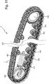
Figure 1 shows a perspective view of a portion of a crawler track according to a first particular embodiment of the present invention; -
Figure 2 shows a perspective exploded view of two links of the track ofFigure 1 ; -
Figure 3 shows a perspective view of a link ofFigure 2 , partially sectioned according to an ideal plane crossing the axis of one of the pins; -
Figure 4 shows a perspective view of a link of a crawler track according a second particular embodiment of the invention, partially sectioned according to an ideal plane crossing the axis of one of the pins; -
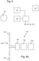
Figure 5 shows a functional diagram of a sensor unit of the crawler track of the other enclosed Figures; -
Figure 5A shows a functional diagram of the rectenna of the sensor unit ofFigure 5 ; -
Figure 6 shows a side view, seen along the direction D1, of a shoe of the track ofFigure 1 ; -
Figure 7 shows a side view, seen along the direction D1, of a shoe according to a third embodiment of the present invention; -
Figure 8 shows a side view, seen along the direction D1, of a shoe and a track link according to a fourth embodiment of the present invention; -
Figure 9 shows a perspective view of a link of a crawler track according a fifth particular embodiment of the invention, partially sectioned according to an ideal plane crossing the axis of one of the pins; -
Figure 10 shows a perspective view of a crawler track according to a sixth particular embodiment of the present invention; -
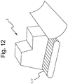
Figure 12 shows a perspective view of a heavy duty vehicle provided with the crawler track ofFigure 1 . -
Figures 1-3 ,5 ,5A ,6 ,11 relate to a first particular embodiment of the present invention. - Like for example in
Figure 1 , acrawler track 1 according to a particular embodiment of the invention can comprise a sequence oftrack links 20 connected to each other through a plurality of articulatedjoints 30 each of which can comprise for example a pin 31 (Figures 2-4 ). - Each
pin 31 can be for example inserted in abushing 32 so as to allow two track links to be rotatably connected one to another. - Each
track link 20 can comprise for example a pair of twoopposite plates 21. - Each
plate 21 can form afirst end portion 22 and asecond end portion 23 parallel to each other and preferably connected to each other by atransversal portions 24. - The
plates 21 can be shaped in such a way that, when thetrack link 20 is assembled, the interspace between thefirst end portions 22 of the pair of theplates 21 of eachtrack link 20 is greater than the interspace between thesecond end portions 23. - The
first end portion 21 and thesecond end portion 23 are provided with respective throughholes pin 31 and to thebushing 32 respectively. - The
first end portion 22 can be provided with anannular groove 27 around its throughhole 25. - Such annular groove preferably has an internal diameter which is greater than the internal diameter of the through
holes 25. - The
annular grooves 27 preferably house arespective sealing system 40. - The
track 1 can be of the lubricated type or of the grease type. - As shown for example in
Figure 3 , in atrack 1 of the grease type some lubricating grease can be provided between the inner surface of thebushings 32 and the outer surface of therespective pins 31, thesealing system 40 can comprise for example anannular sealing 41, preferably made of polyurethane, that engages with the ends of thepin 31, and aspacer ring 42 preferably made of metal. - As shown for example in
figure 4 in atrack 1 of the lubricated type, thepins 31 can be provided with aninternal duct 33 opened at one end of thepin 31 and in fluidic communication with the outside of thepin 31 through onesecondary duct 34 at the region covered by therelative bushing 32. - Then, during the normal operation of the track the lubricant can enter the
duct 33 through the open end of thepin 31 and exit through thesecondary duct 34. - Each row of
track links 20 connected together forms a sort of chain. - The
plates 21,pins 31 andbushings 32 are preferably made of steel or another metal. - The
crawler track 1 further comprises a plurality of shoes 44 (Figures 1 ,6 ), each of which is fixed to arespective track link 20. - The
shoes 44 can be made of steel or another metal, or of a suitable polymeric material, such as relative hard plastic or rubber. - Each
shoe 44 is preferably fixed to a face of the respective track link lying substantially parallel or longitudinal to the advance direction DAD of thetrack link 20 during the normal operation. - Each
shoe 44 preferably comprises: - a
main plate 440; and - at least one
advancement rib 442 protruding from themain plate 440, preferably extending perpendicularly or however transversally to the advance direction DAD of thetrack link 20 and theshoe 44 itself; - Each
advancement rib 442 can lie substantially in a plane of other ideal surface perpendicular to the advance direction DAD of thetrack link 20 and theshoe 44 itself. - Each main plate can have a substantially planar overall shape.
- Each
advancement rib 442 can have the shape of a wall, for example substantially planar and possibly tapered. - The
crawler track 1 can be mounted on a vehicle such as a bulldozer (Figure 12 ), excavator, mobile drill or other heavy duty track vehicle. - More particularly the
crawler track 1 can be part of an undercarriage assembly of a vehicle. - The wording "undercarriage assembly" in the present description means an assembly comprising one or more tracks allowing the vehicle to move, and a frame and possible wheels, pulleys or rollers on which the track or tracks are mounted, possible motors or other actuators, gearboxes of joints driving the tracks, possible power supply lines such as electric or hydraulic power lines powering said motors or other actuators.
- An example of
undercarriage 4 is shown inFigure 11 , comprising atrack 1, onedriving wheel 400, one idlemain wheel 404, a plurality oftrack rollers 406 and a plurality ofcarrier rollers 407. - More generally, an undercarriage can comprise one or more of the following elements:
atrack 1, adriving wheel 400, an idlemain wheel 404, one ormore track rollers 406, one ormore carrier rollers 407 - According to an aspect of the present invention, a heavy duty vehicle 2 can comprise the the
crawler track 1 and: - at least one
sensor crawler track 1 itself, of the heavy duty vehicle 2 or of the environment contained or surrounding thecrawler track 1 or the heavy duty vehicle 2; - a
power supply unit 102 configured for supplying saidsensor - According to a particular embodiment of the invention, the
crawler track 1, 1' can be provided with said at least onesensor - The
power supply unit 102 comprises arectenna 1020 configured for receiving electromagnetic power from an externalelectromagnetic source 104 and for supplying saidsensor - The external
electromagnetic source 104 is preferably a source of electromagnetic microwaves, having a frequency preferably comprised between 300 Mhz-300 GHz - The rectenna 1020 (
Figure 5A ) preferably comprises anantenna 1024 and arectifying circuit 1022 powered by theantenna 1024. - The
antenna 1024 can be for example a dipole comprising two lengths of a conducting wire orrod 1025, one or more grids or one or more metal plates made of a metal or another suitable electrical conductor material. - The
rectifying circuit 1022 can comprise for example a Schottky diode connected at the terminals of theantenna 1024 or a more complex rectifying circuit. - As shown for example in
Figure 5A , therectenna 1020 can comprise ahigh frequency filter 1026 and/or a directcurrent filter 1028. - The
high frequency filter 1026 is configured for cutting the frequencies of the currents generated by theantenna 1024 higher than a predetermined first frequency threshold, and for powering therectifying circuit 1022. - The direct
current filter 1028 can be configured for further smoothing the current or voltage produced by therectifying circuit 1022. - The
rectifying circuit 1022 powers thesensor - Each
sensor receiver unit 103, configured for transmitting the detections of therespective sensor logic unit 105. - The
logic unit 105 can be for example a computer or another microprocessor device. - The
logic unit 105 can be for example mounted on board of the vehicle mounting thetrack 1, and can communicate preferably wireless with the one or more emitter andreceiver unit 103 mounted on thetrack 1. - In the alternative the logic unit can be remote from the vehicle mounting the track or tracks 1, and can be for example a remote server arranged several meters or kilometres away from the vehicle.
- Preferably each emitter and
receiver unit 103 is powered by arectenna 1020, for example by therectenna 1020 powering thesensor receiver unit 103 communicates with. - One
rectenna 1020, one ormore sensors receiver unit 103 can form a small and compact sensor unit easy to be mounted in many parts of thecrawler track 1. - The
parts - The
sensor - The vibration sensor can be -or comprise- for example an accelerometer, since the latter can be used for measuring or detecting vibrations.
- The noise sensor can be or comprise for example a microphone.
- The ultrasonic sensor can emit for example ultrasounds within the track-, shoe, plate or link material or within other material the wearing of which needs to be measured, and then detect their echoes which are affected by the shape and dimensions -and hence by the wear- of the part in which the ultrasounds travels and are reflected.
- As shown in
Figure 6, 7 , in a particular embodiment thesensor advancement rib 442 of arespective shoe 44. - As shown in
Figure 6 , thewear sensor advancement rib 442, that is at or near the region at which theadvancement rib 442 is fixed to themain plate 440, and can be configured for measuring the thickness THW1 of the material of therib 442 interposed between thesensor advancement rib 442 itself (Figure 6 ), for example emitting electromagnetic or acoustic waves within the shoe material and detecting their echoes which are affected by the shape and dimensions of therib 442. - In other words, the
sensor 100 measures the wear of theadvancement rib 442. - As shown in
Figure 7 , the wear sensor 100' can extend over the whole height THW2 of therib 442 and comprise a device for measuring the electric resistance, inductance or capacitance between the tip and the base of therib 442. - To this purpose the wear sensor 100' can be provided with a
resistive element 101 having for example the shape of a rod or plate, extending over the whole height THW2 of therib 442 and having an electric resistance preferably different from that of the surrounding material -such as metal- of therib 442. - To this end the
resistive element 101 can be made of a material different from that of the rest ofrib 442 orshoe 44. - Alternatively the
resistive element 101 can be made of the same material as of the rest ofrib 442 orshoe 44, of be made of a material having the same electrical resistance or resistivity as of the rest ofrib 442 orshoe 44, and theresistive element 101 is electrically insulated from the rest of therib 442 orshoe 44. - More particularly, the sides of the
resistive element 101 can be electrically insulated from the rest of therib 442 orshoe 44. - In any case the height THW2 can be measured for example measuring the electric resistance of the
resistive element 101, since said resistance can be made proportional to or however depending on the height THW2. - As shown in
Figure 8 , in a particular embodiment aplate 21 or more generally atrack link 21 can be provided with one ormore sensors 100 and/or 100' configured for measuring or however detecting a physical quantity of thetrack link 21 or of the environment surrounding it, such as wear of theupper face 212 of theplate 21. - The terms upper and lower referred to the plates and the track links are purely conventional in the present description and referred to when the
shoe 44 is arranged below the consideredtrack link 20 orplate 21, for example when theshoe 44 rests on the ground or a floor during normal operation of the track; however in other instants of operation the same track link can be turned upside down and have itsupper face 212 below itslower face 210. - The
upper face 212 can be subject to wear for example because it rolls and slightly slides against some wheels or rolls (not shown but per se known) of the undercarriage assembly of the vehicle. - Such wheels of rolls can be idle or driving wheels/rolls respectively.
- As already explained about the
shoe 44, thepossible sensor 100 of theplate 21 can be configured for measuring or detecting wear by detecting echoes of an acoustic or electromagnetic waves emitted in the material of theplate 21, for example reflected by theupper surface 212. - As already explained about the shoe 44', the possible sensor 100' of the
plate 21 can be configured for measuring or detecting wear by detecting resistance and changes thereof of a predetermined body, such as aresistive element 101 already described. - Mounting
sensors 100 instead ofsensors 100', 100" or vice versa can depend for example on the overall dimensions of the sensors themselves or on structural reasons. - As shown in
Figure 9 , in a particular embodiment the track link 20' or more generally a crawler track can be provided with one ormore temperature sensors 100", 100III configured for measuring or however detecting the temperature of the track link 20' itself. - More particularly, the
temperature sensors 100", 100III can be configured for detecting the temperature at least of the lubricant present in the track link 20'. - To this purpose, if an annular or tubular chamber is present between the outer surface of a
pin 31 and the inner surface of therespective bushing 32, and lubricating grease, oil or another lubricant fluid is present in such annular or tubular chamber, thetemperature sensor 100III can be arranged on the inner surface of thebushing 32 and/or thetemperature sensor 100" can be arranged on the outer surface of apin 31 so that thesensors 100", 100III contact the lubricant, for example so as to be wetted or licked by it. - Advantageously the
temperature sensor 100III are arranged so as to measure a temperature influenced by both the temperature of the metal -or other solid parts- of the track, shoe, link, pin or other part of an undercarriage or heavy duty vehicle and the temperature of the oil or another lubricant. - For example the
temperature sensor 100", 100III can be arranged so as to be in contact with both the metal -or another solid part- of the heavy duty vehicle or part thereof and the lubricant. - To this purpose, the
temperature sensor 100", 100III can be arranged in arecess 320 made in thebushing 32 or in arecess 310 made in thepin 31, and both therecesses temperature sensors 100", 100III can be licked by the oil, grease or another lubricant. - This way the
temperature sensors 100", 100III will detect temperature values which will be a sort of - possibly weighted- mean value of the metal and the lubricant temperatures. - Analysing for example the evolution of the temperature detected over the time and other parameters, a suitable algorithm, for example run by the
logic unit 105, can then identify particular conditions, such as the complete absence of lubricant or shortage thereof. - If the
sensors 100", 100III detect an anomalous temperature, that is higher than a predetermined threshold, this can be considered quite a reliable indication of wear due to shortage of lubricant. - The information is quite reliable since the lubricant in a track are generally at ambient temperature.
- Detecting shortage of lubricant provides important informations per se about malfunctions of the track and of the whole vehicle.
- Furthermore detecting shortage of lubricant does not provide a precise measure of the wear, but it is useful for identifying the occurrence of wear if combined with the detections of other kinds of sensors and/or with historical data of the particular track or more generally of the vehicle.
- The
temperature sensor 100III can be arranged in a shallow recess or anotherrecess 320 made in thebushing 32, for example on the inner surface of thebushing 32. - The
temperature sensor 100" can be arranged in a shallow recess or anotherrecess 310 made in thepin 31, for example on the outer surface of thepin 31. - Alternatively the
temperature sensors 100", 100III can be arranged in aninternal lubrication duct 33 if present, so as to detect the temperature of the oil or other liquid lubricant. - The undercarriage assembly or the vehicle on which the
crawler track 1 is mounted are advantageously provided with theabovementioned microwave source 104, that is with a suitable microwave generator. - Advantageously the undercarriage assembly or the vehicle on which the
crawler track 1 is mounted are provided with one or more suitable waveguides configured for containing the microwaves produced by theonboard generator 104 or at least reducing their diffusion around the undercarriage assembly or vehicle, and directing the microwaves to one or more rectennas 1020. - Each waveguide can comprise one or more upstream ends and one or more downstream ends.
- Each upstream end is arranged at or near one or
more microwave generators 104 and are configured for allowing propagation of the microwaves within the waveguide. - Each downstream end is arranged at or near one or more rectennas 1020 and are configured for directing to that rectennas the microwaves coming from the
generator 104. - Since they eliminate or significantly reduce the diffusion of the microwaves around the vehicle equipped with the
track 1 andrectennas 1020, the waveguide or waveguides reduces harms to the persons near the vehicle, in particular to its driver and other staff. - An example of a possible way of operation and use of the
track 1 and respective vehicle will now be described. - The waveguide contains and directs the microwaves generated by the
microwave source 104 towards one or more rectennas 1020, powering therectennas 1020 preferably even when the vehicle is travelling on one ormore tracks 1. - Each
rectenna 1020 powers one morerespective sensor receiver units 103. - Hence the
wear sensors 100, 100', thetemperature sensors 100", 100III or other sensors can be powered while the track is operating in a wireless way, with no electrical contacts between thetrack 1 and the rest of the undercarriage assembly or of the vehicle, and for example with no need of powering them with electric local batteries arranged close to the sensors themselves. - The relevant costs for replacing the local batteries can be thus saved.
- The operation and advantages of
rectennas 1020 andrespective sensors - A suitable onboard or remote computer or
other logic unit 105 can receive -for example wireless- the detections of thesensors receiver unit 103 and receive data or commands from thelogic unit 105. - The
logic unit 105 can manage an electronic database storing the detections ofsensors - Depending on the detections of
sensors advancement rib 442, anoverheated pin 31 orbushing 32, lack of lubricant in atrack link 20 or more generally in thecrawler track 1. - An alarm signal can be emitted for example when a
sensor 100, 100' detects an excessively small height THW1, THW2 respectively. - The
logic unit 105 can communicate and exchange informations with thesensors - Alternatively the
sensors logic unit 105. - Said local memories can have a capacity for example comprised between 10 byte-100 Gigabyte, between 50 bytes-1 Gigabyte or between 100 bytes-1 Megabyte.
- The previous teachings allow powering sensors in positions of a vehicle, in which wired powering is difficult or impossible, like in the case of sensors arranged on a crawler track.
- More particularly rectennas allow powering sensors even deeply enclosed within movable parts such as within the links and hinge pins of a track link, entailing very low maintenance and management costs: for example rectennas eliminate the costs of periodically replacing a great number of local batteries powering the sensors and arranged in the chain links, or eliminate the costs of sliding contacts along the power supply lines.
- Rectennas allow a great number of sensors be easily set and powered on the same vehicle, with no significant growth of costs and complexity of the installation as the number of sensors increases: in fact such costs can be considered to grow about linearly or less than linearly with the increase of the sensor number.
- The sensors can be duly protected and powered even if placed in a very harsh environment such that surrounding a crawler track, with abundant mud, grease, sand, stones and dirt in general, and with heavy mechanical and chemical stresses in general.
- Such ease of installing and powering a great number of sensors allow a great number of physical quantities of a crawler track be constantly monitored, such as wear, temperature of critical parts or areas, shortage of lubricant, significantly reducing the running and maintenance costs of the tracks and consequently of the whole vehicle.
- Monitoring these physical quantities in real time furthermore allows reducing the occurrence of critical situations and failures.
- The embodiments previously described can be modified in several ways without departing from the scope of the present invention.
- For instance the vehicle or track can be provided not only with wear or temperature sensors, but also with other kinds of sensors powered by one or more rectennas, for example accelerometers, load cells and other pressure- or force sensors, sensors for detecting specific substances, chemical sensors in general.
- All constructional details can be replaced with technically equivalent elements.
- A wording such as "A comprises B, C, D" or "A is made up of B, C, D" is to be understood as encompassing and disclosing the particular case of "A consists of B, C, D".
- The wording "A comprises an element B" unless specified otherwise is to be understood as encompassing and disclosing the particular case of "A comprises one or more elements B".
- The lists of possible modifications and variants are to be understood as non-exhaustive.
Claims (15)
- Heavy duty vehicle (2) comprising:- a crawler track (1, 1') on which the rest of the vehicle can roll so as to move;- at least one sensor (100, 100', 100", 100III ) configured for detecting a physical quantity of the crawler track (1) itself, of the heavy duty vehicle (2) or of the environment contained or surrounding the crawler track (1) or the heavy duty vehicle;- a power supply unit (102) configured for supplying said sensor with electric power;
wherein the power supply unit (102) comprises a rectenna (1020) configured for receiving electromagnetic power from an external electromagnetic source (104) and for supplying said sensor (100, 100', 100", 100III ) with at least part of said electromagnetic power. - Heavy duty vehicle (2) according to claim 1, wherein the crawler track (1, 1') is provided with said at least one sensor (100, 100', 100", 100III ).
- Heavy duty vehicle (2) according to claim 1 or 2, wherein said sensor (100, 100', 100", 100III ) is chosen from the following group: a temperature sensor, a wear sensor configured for detecting the wear of a part of the crawler track, a pressure sensor, a load cell, an accelerometer, a noise-, vibration or ultrasound sensor, a receiver of a global positioning system such as GPS, GLONASS, GALILEO or BEIDOU.
- Heavy duty vehicle (2) according to one or more preceding claims, wherein said crawler track (1, 1') comprises at least one shoe (44, 44') configured for being laid on a floor or ground on which the crawler track (1) can move forward, wherein the at least one shoe (44, 44') comprises:- a main plate (440);- at least one advancement rib (442) protruding from the main plate (440);
wherein said at least one sensor (100, 100', 100", 100III ) is a wear sensor configured for detecting the wear of the advancement rib (442). - Heavy duty vehicle (2) according to one or more preceding claims, wherein said crawler track (1, 1') comprises a plurality of track links (20) connected together to as to form a chain extending along the crawler track (1) itself, wherein:- the track links (20) are arranged for resting on a floor or ground;- the at least one sensor is:- a wear sensor (100, 100') configured for detecting wear of one of the track links or another part of the crawler track;- a temperature sensor (100", 100III ) configured for detecting the temperature of one or more of the track links (20) or of the other parts or environment surrounding said temperature sensor.
- Heavy duty vehicle (2) according to claim 5, wherein at least one of said track links (20) is fixed to said at least one shoe (44, 44') and is arranged for resting on said shoe, and said wear sensor (100, 100') is configured for detecting wear of one or more of said track links (20) and/or of said at least one shoe (44, 44').
- Heavy duty vehicle (2) according to claim 5 or 6, wherein said crawler track (1, 1') comprises a plurality of hinge pins (31) connecting said track links (20) so as to form an articulated chain, wherein said at least one sensor (100", 100III ) is a temperature sensor arranged for measuring the temperature of at least one of said hinge pins (31).
- Heavy duty vehicle (2) according to claim 7, wherein said temperature sensor (100") is arranged in or on one of said hinge pins (31).
- Heavy duty vehicle (2) according to one or more of the preceding claims, wherein:- the crawler track (1') forms an internal main face (1000) and an external main face (1001) and at least one advancement rib (442") protruding transversally from the external main face (1001);- the external main face (1001) is configured for resting on a floor or ground on which the crawler track (1') can move forward,- said at least one sensor (100, 100', 100", 100III ) is a wear sensor (100, 100') configured for detecting the wear of the advancement rib (442").
- Heavy duty vehicle (2) according to claim 4 and/or 9, wherein the at least one advancement rib (442, 442") extends transversally to the direction of forward motion (DAD) of the crawler track or transversally to the crawler track (1') itself.
- Heavy duty vehicle (2) according to one or more preceding claims, comprising an external electromagnetic source (104) configured for emitting microwaves suitable for powering said rectenna (1020).
- Crawler track (1, 1') of a vehicle, comprising:- at least one sensor (100, 100', 100", 100III ) configured for detecting a physical quantity of the crawler track (1) itself or of the environment contained or surrounding the crawler track (1, 1');- a power supply unit (102) configured for supplying said sensor with electric power;
wherein the power supply unit (102) comprises a rectenna (1020) configured for receiving electromagnetic power from an external electromagnetic source (104) and for supplying said sensor (100, 100', 100", 100III ) with at least part of said electromagnetic power. - Shoe (44, 44') for a crawler track (1, 1') of a heavy duty vehicle, comprising:- at least one sensor (100, 100') configured for detecting a physical quantity of the shoe (44, 44') itself or of the environment contained or surrounding the shoe (44, 44'),- a power supply unit (102) configured for supplying said sensor (100, 100') with electric power;
wherein the power supply unit (102) comprises a rectenna (1020) configured for receiving electromagnetic power from an external electromagnetic source (104) and for supplying said sensor (100, 100') with at least part of said electromagnetic power. - Track link (20) of a crawler track (1, 1') of a heavy duty vehicle, comprising:- at least one sensor (100, 100', 100", 100III ) configured for detecting a physical quantity of the track link (20) itself or of the environment contained in or surrounding the track link (20);- a power supply unit (102) configured for supplying said sensor (100, 100', 100", 100III ) with electric power;
wherein the power supply unit (102) comprises a rectenna (1020) configured for receiving electromagnetic power from an external electromagnetic source (104) and for supplying said sensor with at least part of said electromagnetic power. - Undercarriage assembly for a heavy duty track-type vehicle (2) such as a bulldozer, excavator, mobile drills or other heavy equipment vehicles, the undercarriage assembly comprising:- a crawler track (1, 1') having the features according to one or more claims 1-10; and- an external electromagnetic source (104) configured for emitting microwaves suitable for powering said rectenna (1020).
Priority Applications (6)
| Application Number | Priority Date | Filing Date | Title |
|---|---|---|---|
| EP19425029.6A EP3723296A1 (en) | 2019-04-12 | 2019-04-12 | Crawler track, shoe, track link, undercarriage assembly and vehicle provided with a power supply unit for powering sensors |
| CN202080028124.4A CN114258638B (en) | 2019-04-12 | 2020-04-09 | Track drive, track shoe, track link, chassis assembly and vehicle |
| EP20716826.1A EP3954052A1 (en) | 2019-04-12 | 2020-04-09 | Crawler track, shoe, track link, undercarriage assembly and vehicle provided with a power supply unit for powering sensors |
| PCT/EP2020/060243 WO2020208179A1 (en) | 2019-04-12 | 2020-04-09 | Crawler track, shoe, track link, undercarriage assembly and vehicle provided with a power supply unit for powering sensors |
| US17/602,964 US12583539B2 (en) | 2019-04-12 | 2020-04-09 | Crawler track, shoe, track link, undercarriage assembly and vehicle provided with a power supply unit for powering sensors |
| KR1020217036340A KR102561385B1 (en) | 2019-04-12 | 2020-04-09 | Crawler tracks, shoes, track links, undercarriage assemblies and vehicles provided with a power supply unit to power the sensors. |
Applications Claiming Priority (1)
| Application Number | Priority Date | Filing Date | Title |
|---|---|---|---|
| EP19425029.6A EP3723296A1 (en) | 2019-04-12 | 2019-04-12 | Crawler track, shoe, track link, undercarriage assembly and vehicle provided with a power supply unit for powering sensors |
Publications (1)
| Publication Number | Publication Date |
|---|---|
| EP3723296A1 true EP3723296A1 (en) | 2020-10-14 |
Family
ID=66476585
Family Applications (2)
| Application Number | Title | Priority Date | Filing Date |
|---|---|---|---|
| EP19425029.6A Withdrawn EP3723296A1 (en) | 2019-04-12 | 2019-04-12 | Crawler track, shoe, track link, undercarriage assembly and vehicle provided with a power supply unit for powering sensors |
| EP20716826.1A Pending EP3954052A1 (en) | 2019-04-12 | 2020-04-09 | Crawler track, shoe, track link, undercarriage assembly and vehicle provided with a power supply unit for powering sensors |
Family Applications After (1)
| Application Number | Title | Priority Date | Filing Date |
|---|---|---|---|
| EP20716826.1A Pending EP3954052A1 (en) | 2019-04-12 | 2020-04-09 | Crawler track, shoe, track link, undercarriage assembly and vehicle provided with a power supply unit for powering sensors |
Country Status (5)
| Country | Link |
|---|---|
| US (1) | US12583539B2 (en) |
| EP (2) | EP3723296A1 (en) |
| KR (1) | KR102561385B1 (en) |
| CN (1) | CN114258638B (en) |
| WO (1) | WO2020208179A1 (en) |
Families Citing this family (6)
| Publication number | Priority date | Publication date | Assignee | Title |
|---|---|---|---|---|
| EP4177140B1 (en) | 2021-11-03 | 2024-08-28 | Berco S.p.A. | Track link assembly |
| WO2023135319A1 (en) | 2022-01-17 | 2023-07-20 | Berco S.P.A. | Track link assembly with wear sensing device |
| US20230366842A1 (en) * | 2022-05-12 | 2023-11-16 | Caterpillar Inc. | Bushing wear monitoring |
| US20230400291A1 (en) * | 2022-06-13 | 2023-12-14 | Caterpillar Inc. | Detecting wear of track link pin based on sensor data of a sensor device provided in a cavity of the track link pin |
| CN115574993B (en) * | 2022-09-05 | 2025-08-22 | 太原科技大学 | An embedded anti-overload test sensing system for tracked travel structures |
| US12345605B2 (en) * | 2023-03-03 | 2025-07-01 | Caterpillar Inc. | System, apparatus, computer program product, and method for determining track pitch distance measurement |
Citations (2)
| Publication number | Priority date | Publication date | Assignee | Title |
|---|---|---|---|---|
| WO2017000068A1 (en) * | 2015-06-29 | 2017-01-05 | Camso Inc. | Systems and methods for monitoring a track system for traction of a vehicle |
| US20170261450A1 (en) * | 2016-03-14 | 2017-09-14 | Modustri Llc | Track pin communication system and method |
Family Cites Families (15)
| Publication number | Priority date | Publication date | Assignee | Title |
|---|---|---|---|---|
| US3434678A (en) * | 1965-05-05 | 1969-03-25 | Raytheon Co | Microwave to dc converter |
| US5870026A (en) * | 1997-07-15 | 1999-02-09 | The Morgan Crucible Company Plc | Brush wear indicator |
| US7307589B1 (en) * | 2005-12-29 | 2007-12-11 | Hrl Laboratories, Llc | Large-scale adaptive surface sensor arrays |
| US10046815B2 (en) | 2012-03-27 | 2018-08-14 | Wearpro Incorporated | Wear monitoring device and method of monitoring undercarriage and roller wear |
| US9169623B2 (en) | 2013-04-25 | 2015-10-27 | Caterpillar Inc. | Wear monitoring system for track type machine |
| US9592866B2 (en) * | 2014-11-06 | 2017-03-14 | Caterpillar Inc. | Track assembly having a wear monitoring system |
| US9557244B2 (en) * | 2014-11-10 | 2017-01-31 | Caterpillar Inc. | Thrust bias detection system |
| US20150066291A1 (en) | 2014-11-12 | 2015-03-05 | Caterpillar Inc. | Wear monitoring system for undercarriage component |
| US20150081166A1 (en) | 2014-11-21 | 2015-03-19 | Caterpillar Inc. | Wear monitoring system for a track roller |
| US9784647B2 (en) * | 2014-12-19 | 2017-10-10 | Caterpillar Inc. | Wear sensing device having a housing |
| US9669886B2 (en) * | 2015-02-02 | 2017-06-06 | Caterpillar Inc. | Wear sensing device for a carrier roller |
| EP3353520B1 (en) | 2015-09-21 | 2021-08-11 | Soucy International, Inc. | Smart track system having embedded sensors and method of using the same |
| CN107323548B (en) * | 2017-07-21 | 2023-05-16 | 南京信息职业技术学院 | Self-adaptive speed-regulating type height-limiting emergency device for crawler-type vehicle |
| WO2019097556A1 (en) * | 2017-11-17 | 2019-05-23 | Italtractor Itm S.P.A. | Element of a tracked movement assembly for works machines |
| CA3085012A1 (en) * | 2017-12-08 | 2018-12-07 | Camso Inc. | Systems and methods for monitoring off-road vehicles |
-
2019
- 2019-04-12 EP EP19425029.6A patent/EP3723296A1/en not_active Withdrawn
-
2020
- 2020-04-09 WO PCT/EP2020/060243 patent/WO2020208179A1/en not_active Ceased
- 2020-04-09 KR KR1020217036340A patent/KR102561385B1/en active Active
- 2020-04-09 US US17/602,964 patent/US12583539B2/en active Active
- 2020-04-09 EP EP20716826.1A patent/EP3954052A1/en active Pending
- 2020-04-09 CN CN202080028124.4A patent/CN114258638B/en active Active
Patent Citations (2)
| Publication number | Priority date | Publication date | Assignee | Title |
|---|---|---|---|---|
| WO2017000068A1 (en) * | 2015-06-29 | 2017-01-05 | Camso Inc. | Systems and methods for monitoring a track system for traction of a vehicle |
| US20170261450A1 (en) * | 2016-03-14 | 2017-09-14 | Modustri Llc | Track pin communication system and method |
Also Published As
| Publication number | Publication date |
|---|---|
| WO2020208179A1 (en) | 2020-10-15 |
| EP3954052A1 (en) | 2022-02-16 |
| CN114258638A (en) | 2022-03-29 |
| KR102561385B1 (en) | 2023-07-28 |
| US12583539B2 (en) | 2026-03-24 |
| CN114258638B (en) | 2023-09-05 |
| KR20210147064A (en) | 2021-12-06 |
| US20220185399A1 (en) | 2022-06-16 |
Similar Documents
| Publication | Publication Date | Title |
|---|---|---|
| US12583539B2 (en) | Crawler track, shoe, track link, undercarriage assembly and vehicle provided with a power supply unit for powering sensors | |
| US10046815B2 (en) | Wear monitoring device and method of monitoring undercarriage and roller wear | |
| AU2015307037B2 (en) | Track link having a wear sensing device | |
| CN107041134B (en) | Wear sensing device with housing | |
| CN108778914A (en) | Track pin communication system and method | |
| WO2018204324A1 (en) | Method and system for component wear monitoring | |
| WO2019097556A1 (en) | Element of a tracked movement assembly for works machines | |
| US12552473B2 (en) | Chain pin assembly | |
| US20260015052A1 (en) | Tracked undercarriage roller assembly with temperature monitoring | |
| EP4065450B1 (en) | Monitoring system for belted undercarriage | |
| US20240328461A1 (en) | Device for monitoring the lubrication condition of a bearing of a track roller of a running gear of a tracked vehicle | |
| SE534180C2 (en) | Equipment and method of traffic monitoring | |
| CA3221356A1 (en) | Kit, system and method for real-time, autonomous remote monitoring of wear in a bushing of earth-moving equipment | |
| Castagnetti et al. | A novel ball joint wear sensor for low-cost structural health monitoring of off-highway vehicles | |
| US4140015A (en) | Bearing joint and method of measuring the fluid level therein | |
| US20230366842A1 (en) | Bushing wear monitoring | |
| KR20240049344A (en) | track link gap sensor | |
| KR20250172874A (en) | A sensing system and process for detecting one or more physical parameters of an undercarriage and/or a vehicle, and an undercarriage and a vehicle having the sensing system | |
| AU2022228140A1 (en) | Temperature sensor device, undercarriage assembly and temperature monitoring system of at least one undercarriage component |
Legal Events
| Date | Code | Title | Description |
|---|---|---|---|
| PUAI | Public reference made under article 153(3) epc to a published international application that has entered the european phase |
Free format text: ORIGINAL CODE: 0009012 |
|
| STAA | Information on the status of an ep patent application or granted ep patent |
Free format text: STATUS: THE APPLICATION HAS BEEN PUBLISHED |
|
| AK | Designated contracting states |
Kind code of ref document: A1 Designated state(s): AL AT BE BG CH CY CZ DE DK EE ES FI FR GB GR HR HU IE IS IT LI LT LU LV MC MK MT NL NO PL PT RO RS SE SI SK SM TR |
|
| AX | Request for extension of the european patent |
Extension state: BA ME |
|
| STAA | Information on the status of an ep patent application or granted ep patent |
Free format text: STATUS: THE APPLICATION IS DEEMED TO BE WITHDRAWN |
|
| 18D | Application deemed to be withdrawn |
Effective date: 20210415 |