EP3723245B1 - Bracket assembly for supporting terminal leads in auxiliary generator for aircraft - Google Patents
Bracket assembly for supporting terminal leads in auxiliary generator for aircraft Download PDFInfo
- Publication number
- EP3723245B1 EP3723245B1 EP19212577.1A EP19212577A EP3723245B1 EP 3723245 B1 EP3723245 B1 EP 3723245B1 EP 19212577 A EP19212577 A EP 19212577A EP 3723245 B1 EP3723245 B1 EP 3723245B1
- Authority
- EP
- European Patent Office
- Prior art keywords
- bracket
- auxiliary generator
- stator
- recited
- generator assembly
- Prior art date
- Legal status (The legal status is an assumption and is not a legal conclusion. Google has not performed a legal analysis and makes no representation as to the accuracy of the status listed.)
- Active
Links
Images


Classifications
-
- F—MECHANICAL ENGINEERING; LIGHTING; HEATING; WEAPONS; BLASTING
- F02—COMBUSTION ENGINES; HOT-GAS OR COMBUSTION-PRODUCT ENGINE PLANTS
- F02C—GAS-TURBINE PLANTS; AIR INTAKES FOR JET-PROPULSION PLANTS; CONTROLLING FUEL SUPPLY IN AIR-BREATHING JET-PROPULSION PLANTS
- F02C7/00—Features, components parts, details or accessories, not provided for in, or of interest apart form groups F02C1/00 - F02C6/00; Air intakes for jet-propulsion plants
- F02C7/32—Arrangement, mounting, or driving, of auxiliaries
-
- H—ELECTRICITY
- H02—GENERATION; CONVERSION OR DISTRIBUTION OF ELECTRIC POWER
- H02K—DYNAMO-ELECTRIC MACHINES
- H02K3/00—Details of windings
- H02K3/46—Fastening of windings on the stator or rotor structure
- H02K3/50—Fastening of winding heads, equalising connectors, or connections thereto
-
- B—PERFORMING OPERATIONS; TRANSPORTING
- B23—MACHINE TOOLS; METAL-WORKING NOT OTHERWISE PROVIDED FOR
- B23K—SOLDERING OR UNSOLDERING; WELDING; CLADDING OR PLATING BY SOLDERING OR WELDING; CUTTING BY APPLYING HEAT LOCALLY, e.g. FLAME CUTTING; WORKING BY LASER BEAM
- B23K37/00—Auxiliary devices or processes, not specially adapted for a procedure covered by only one of the other main groups of this subclass
- B23K37/04—Auxiliary devices or processes, not specially adapted for a procedure covered by only one of the other main groups of this subclass for holding or positioning work
- B23K37/0426—Fixtures for other work
- B23K37/0435—Clamps
-
- B—PERFORMING OPERATIONS; TRANSPORTING
- B64—AIRCRAFT; AVIATION; COSMONAUTICS
- B64D—EQUIPMENT FOR FITTING IN OR TO AIRCRAFT; FLIGHT SUITS; PARACHUTES; ARRANGEMENT OR MOUNTING OF POWER PLANTS OR PROPULSION TRANSMISSIONS IN AIRCRAFT
- B64D41/00—Power installations for auxiliary purposes
-
- F—MECHANICAL ENGINEERING; LIGHTING; HEATING; WEAPONS; BLASTING
- F16—ENGINEERING ELEMENTS AND UNITS; GENERAL MEASURES FOR PRODUCING AND MAINTAINING EFFECTIVE FUNCTIONING OF MACHINES OR INSTALLATIONS; THERMAL INSULATION IN GENERAL
- F16M—FRAMES, CASINGS OR BEDS OF ENGINES, MACHINES OR APPARATUS, NOT SPECIFIC TO ENGINES, MACHINES OR APPARATUS PROVIDED FOR ELSEWHERE; STANDS; SUPPORTS
- F16M13/00—Other supports for positioning apparatus or articles; Means for steadying hand-held apparatus or articles
- F16M13/02—Other supports for positioning apparatus or articles; Means for steadying hand-held apparatus or articles for supporting on, or attaching to, an object, e.g. tree, gate, window-frame, cycle
-
- H—ELECTRICITY
- H02—GENERATION; CONVERSION OR DISTRIBUTION OF ELECTRIC POWER
- H02K—DYNAMO-ELECTRIC MACHINES
- H02K1/00—Details of the magnetic circuit
- H02K1/06—Details of the magnetic circuit characterised by the shape, form or construction
- H02K1/12—Stationary parts of the magnetic circuit
- H02K1/18—Means for mounting or fastening magnetic stationary parts on to, or to, the stator structures
- H02K1/185—Means for mounting or fastening magnetic stationary parts on to, or to, the stator structures to outer stators
-
- H—ELECTRICITY
- H02—GENERATION; CONVERSION OR DISTRIBUTION OF ELECTRIC POWER
- H02K—DYNAMO-ELECTRIC MACHINES
- H02K3/00—Details of windings
- H02K3/46—Fastening of windings on the stator or rotor structure
- H02K3/52—Fastening salient pole windings or connections thereto
- H02K3/521—Fastening salient pole windings or connections thereto applicable to stators only
-
- H—ELECTRICITY
- H02—GENERATION; CONVERSION OR DISTRIBUTION OF ELECTRIC POWER
- H02K—DYNAMO-ELECTRIC MACHINES
- H02K5/00—Casings; Enclosures; Supports
- H02K5/04—Casings or enclosures characterised by the shape, form or construction thereof
- H02K5/22—Auxiliary parts of casings not covered by groups H02K5/06-H02K5/20, e.g. shaped to form connection boxes or terminal boxes
-
- H—ELECTRICITY
- H02—GENERATION; CONVERSION OR DISTRIBUTION OF ELECTRIC POWER
- H02K—DYNAMO-ELECTRIC MACHINES
- H02K5/00—Casings; Enclosures; Supports
- H02K5/04—Casings or enclosures characterised by the shape, form or construction thereof
- H02K5/22—Auxiliary parts of casings not covered by groups H02K5/06-H02K5/20, e.g. shaped to form connection boxes or terminal boxes
- H02K5/225—Terminal boxes or connection arrangements
-
- H—ELECTRICITY
- H02—GENERATION; CONVERSION OR DISTRIBUTION OF ELECTRIC POWER
- H02K—DYNAMO-ELECTRIC MACHINES
- H02K1/00—Details of the magnetic circuit
- H02K1/06—Details of the magnetic circuit characterised by the shape, form or construction
- H02K1/12—Stationary parts of the magnetic circuit
- H02K1/18—Means for mounting or fastening magnetic stationary parts on to, or to, the stator structures
-
- H—ELECTRICITY
- H02—GENERATION; CONVERSION OR DISTRIBUTION OF ELECTRIC POWER
- H02K—DYNAMO-ELECTRIC MACHINES
- H02K3/00—Details of windings
- H02K3/46—Fastening of windings on the stator or rotor structure
- H02K3/52—Fastening salient pole windings or connections thereto
- H02K3/521—Fastening salient pole windings or connections thereto applicable to stators only
- H02K3/522—Fastening salient pole windings or connections thereto applicable to stators only for generally annular cores with salient poles
-
- H—ELECTRICITY
- H02—GENERATION; CONVERSION OR DISTRIBUTION OF ELECTRIC POWER
- H02K—DYNAMO-ELECTRIC MACHINES
- H02K5/00—Casings; Enclosures; Supports
- H02K5/24—Casings; Enclosures; Supports specially adapted for suppression or reduction of noise or vibrations
Definitions
- the subject invention is directed to a bracket assembly, and more particularly, to a two-piece bracket assembly for supporting a plurality of terminal leads within the stator housing of an auxiliary generator for an aircraft.
- APU Auxiliary Power Unit
- An APU typically in the form of an independent gas turbine engine, provides shaft power to drive a generator and interconnected electrical systems.
- auxiliary generators there are a plurality of terminal leads that are located within a stator housing of the generator, transferring electrical output from the stator to external terminals for output to the aircraft.
- These terminal leads are typically unsupported within the housing and therefore subject to damage from vibration. More particularly, the braze joints used to connect the terminal leads to the terminal bock of the generator are susceptible to damage due to resonance and/or externally induced vibration.
- the subject invention is directed to a novel bracket assembly that is adapted and configured to support the terminal leads within the stator housing in such a manner so that they are not susceptible to failure from resonance and vibration.
- US 2014/319939 A1 , US 6104116 A and US 2008/073987 A1 each disclose a known bracket assembly.
- an auxiliary generator assembly comprising an auxiliary generator and a bracket assembly according to claim 1.
- the first bracket is adapted and configured to be fastened at existing fastener locations previously used for fastening a pair of circumferentially spaced apart stator flange washers.
- the second bracket includes a plurality of mounting locations to accommodate a plurality of terminal lead clamps.
- the bracket assembly further includes a plurality of terminal lead clamps for securing the terminal leads to a top surface of the second bracket.
- the first bracket is formed from a metal material, and preferably, the first bracket is formed from steel.
- the second bracket is formed from a non-metallic material, and preferably, the second bracket is formed from a thermoset plastic.
- the first bracket has a generally arcuate configuration extending through a first arc length and the second bracket has a generally arcuate configuration extending through a second arc length that is less than the first arc length.
- the first bracket has a stepped protrusion on a bottom surface thereof for contacting a stator sleeve to apply a preload force thereto to prevent vibration of the component parts of the bracket assembly.
- auxiliary generator assembly of the subject invention configured to be fastened to a stator housing of the generator at existing fasteners locations previously used for fastening a pair of circumferentially spaced apart stator flange washers, and serving to retain a main stator within the stator housing, and a second non-metallic bracket adapted and configured to be fastened to a top surface of the first bracket and including mounting locations for supporting a plurality of terminal lead clamps.
- the bracket assembly includes a plurality of terminal lead clamps for securing a corresponding number of terminal leads to a top surface of the second bracket.
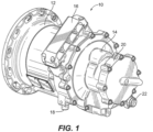
- auxiliary generator that is designated generally by reference numeral 10, that includes the novel bracket assembly of the subject invention, which will be described in detail below.
- the auxiliary generator 10 forms part of the Auxiliary Power Unit (APU) of a commercial passenger aircraf.
- the generator 10 has an input stator housing 12 at one end which includes a terminal block 16 and an electrical connector 18.
- the generator 10 also includes an input shaft (not shown), a central stator housing 14 having another electrical connector 22, and a cover 20 that is bolted to the central stator housing 14.
- Fig. 2 which depicts a prior art configuration of the generator 10, there is located within the input stator housing 12, four terminal leads 30a-30d, which are associated with the terminal block 16. These include two outer terminal leads 30a, 30d and two inner terminal leads 30b, 30c. The outer terminal leads 30a, 30d are longer than the inner terminal leads 30b, 30c. These four terminal leads 30a-30d are individually connected to the terminal block 16 using typical braze joints. They are otherwise unsupported within the input stator housing 12 of the generator 10, and therefore they are subject to vibration damage. More particularly, it has been determined through testing and evaluation that the braze joints used to connect the four terminal leads 30a-30d to the terminal block 16 in the prior art configuration of generator 10 are susceptible to damage due to resonance and vibration, which is problematic.
- stator flange washers 24a-24c that are fastened to the stator housing flange 28 at specific locations about the outer periphery of the input stator housing 12. These include flange washer 24a located at the 2 o'clock position, flange washer 24b located at the 6 o'clock position and flange washer 24c located at the 10 o'clock position.
- the flange washers 24a and 24c have been removed from the flange 28 of stator housing 12 and the mounting locations that were used for those two flange washers 24a, 24c are preferably used as mounting locations for a novel bracket assembly used to support the terminal leads 30a-30d in such a manner so that they are not susceptible to failure due to resonance and vibration. That is, in an improved configuration of generator 10, the two mounting locations 26a and 26b that are associated with washer 24a and the two mounting locations 26c and 26d that are associated with washer 24c are used as mounting locations for the novel bracket assembly of the subject invention.
- the subject invention includes a bracket assembly designated generally by reference numeral 50, for supporting the terminal leads 30a-30d in the stator housing 12 of auxiliary generator 10.
- the bracket assembly 50 includes a first bracket 52 adapted and configured to be fastened to the stator housing 12 of the generator 10 at the existing fasteners locations 26a-26d that were previously used for fastening stator flange washers 24a and 24c, and serving to retain the main stator within the stator housing 12.
- the first bracket 52 has four fastener ports 23a-23d for receiving four fasteners 25a-25d that are employed at fastener locations 26a-26d to secure the first bracket 52 of bracket assembly 50 to the stator housing 12.
- the bracket assembly 50 includes a second bracket 54 adapted and configured to be fastened to a raised top mounting surface portion 52a of the first bracket 52 at four fastener locations 53a-53d, using four corresponding fasteners 55a-55d that extend through four apertures 57a-57d in the second bracket 54.
- the bracket assembly 50 further includes four generally P-shaped terminal lead clamps 56a-56d for respectively securing the four terminal leads 30a-30b to the top surface 54a of the second bracket 54.
- the second bracket 54 of bracket assembly 50 includes four mounting ports 58a-58d for respectively receiving corresponding fasteners 60a-60d that secure the terminal clamps 56a-56d to the second bracket 54 of bracket assembly 50.
- the first bracket 52 of bracket assembly 50 has a generally arcuate configuration extending through a first arc length and the second bracket 54 of bracket assembly 50 has a generally arcuate configuration extending through a second arc length that is less than the first arc length.
- the bracket assembly 50 has a di-electric construction. More particularly, the first bracket 52 of bracket assembly 50 is formed from a metal material and the second bracket 54 of bracket assembly 50 is formed from a thermoset plastic material. In particular, the first bracket 52 of bracket assembly 50 is formed from steel or a similar metal material, and the second bracket 54 of bracket assembly 50 is formed from a polyamide-imide or a similar plastic material.
- the first bracket 52 of bracket assembly 50 has a stepped protrusion 64 formed at the center of a bottom surface 52b thereof for contacting an annular stator sleeve 66 that is associated with the peripheral edge of the main stator flange 28 of the stator housing 12 of generator 10.
- the stepped protrusion 64 of bracket 52 is designed to advantageously apply a preload or bending force to the bracket 52 and therefore the bracket assembly 50 as a whole, to prevent vibration of the component parts of the bracket assembly 50. This is will further prevent or otherwise inhibit damage or disruption to the connections between the terminal leads 30a-30d and terminal block 16 of the stator housing 12, which is best seen for example in Fig. 7 .
Landscapes
- Engineering & Computer Science (AREA)
- Power Engineering (AREA)
- Mechanical Engineering (AREA)
- General Engineering & Computer Science (AREA)
- Chemical & Material Sciences (AREA)
- Combustion & Propulsion (AREA)
- Physics & Mathematics (AREA)
- Optics & Photonics (AREA)
- Aviation & Aerospace Engineering (AREA)
- Motor Or Generator Frames (AREA)
Description
- The subject invention is directed to a bracket assembly, and more particularly, to a two-piece bracket assembly for supporting a plurality of terminal leads within the stator housing of an auxiliary generator for an aircraft.
- Many commercial passenger aircraft have an Auxiliary Power Unit (APU) that is used in conjunction with the main propulsion engines to provide a secondary source of power. An APU, typically in the form of an independent gas turbine engine, provides shaft power to drive a generator and interconnected electrical systems.
- In certain auxiliary generators, there are a plurality of terminal leads that are located within a stator housing of the generator, transferring electrical output from the stator to external terminals for output to the aircraft. These terminal leads are typically unsupported within the housing and therefore subject to damage from vibration. More particularly, the braze joints used to connect the terminal leads to the terminal bock of the generator are susceptible to damage due to resonance and/or externally induced vibration.
- The subject invention is directed to a novel bracket assembly that is adapted and configured to support the terminal leads within the stator housing in such a manner so that they are not susceptible to failure from resonance and vibration.
US 2014/319939 A1 ,US 6104116 A andUS 2008/073987 A1 each disclose a known bracket assembly. - According to a first aspect, there is provided an auxiliary generator assembly comprising an auxiliary generator and a bracket assembly according to claim 1.
- In accordance with an embodiment of the subject invention, the first bracket is adapted and configured to be fastened at existing fastener locations previously used for fastening a pair of circumferentially spaced apart stator flange washers. The second bracket includes a plurality of mounting locations to accommodate a plurality of terminal lead clamps. The bracket assembly further includes a plurality of terminal lead clamps for securing the terminal leads to a top surface of the second bracket.
- The first bracket is formed from a metal material, and preferably, the first bracket is formed from steel. The second bracket is formed from a non-metallic material, and preferably, the second bracket is formed from a thermoset plastic. The first bracket has a generally arcuate configuration extending through a first arc length and the second bracket has a generally arcuate configuration extending through a second arc length that is less than the first arc length. Preferably, the first bracket has a stepped protrusion on a bottom surface thereof for contacting a stator sleeve to apply a preload force thereto to prevent vibration of the component parts of the bracket assembly.
- These and other features of the auxiliary generator assembly of the subject invention will become more readily apparent to those having ordinary skill in the art to which the subject invention appertains from the detailed description of the preferred embodiments taken in conjunction with the following brief description of the drawings. configured to be fastened to a stator housing of the generator at existing fasteners locations previously used for fastening a pair of circumferentially spaced apart stator flange washers, and serving to retain a main stator within the stator housing, and a second non-metallic bracket adapted and configured to be fastened to a top surface of the first bracket and including mounting locations for supporting a plurality of terminal lead clamps. In addition, the bracket assembly includes a plurality of terminal lead clamps for securing a corresponding number of terminal leads to a top surface of the second bracket.
- These and other features of the bracket assembly of the subject invention will become more readily apparent to those having ordinary skill in the art to which the subject invention appertains from the detailed description of the preferred embodiments taken in conjunction with the following brief description of the drawings, the invention being defined by the appended claims.
- So that those having ordinary skill in the art will readily understand how to make and use the subject invention without undue experimentation, preferred embodiments thereof will be described in detail herein below with reference to the figures wherein:
-
Fig. 1 is a perspective view of an auxiliary generator that includes the bracket assembly of the subject invention; -
Fig. 2 is an interior elevational view of the auxiliary generator shown inFig. 1 , with the center housing and cover removed to illustrate the prior art configuration of the terminal leads, which are unsupported within the stator housing of the generator relative to the main stator, and which includes three circumferentially spaced apart stator flange washers; -
Fig. 3 is an interior elevational view of the auxiliary generator shown inFig. 1 , with the center housing and cover removed to illustrate the bracket assembly of the subject invention, which is installed in the stator housing to retain the main stator and restrain the terminal leads, using existing mounting locations of the stator flange washers; -
Fig. 4 is an exploded perspective view of the bracket assembly of the subject invention separated from the stator housing; -
Fig. 5 is a perspective view of the bracket assembly of the subject invention; -
Fig. 6 is an enlarged localized view of the bracket assembly of the subject invention, taken along line 6-6 ofFig. 4 , when it is being installed in the stator housing, relative to the main stator sleeve, with a protrusion on the bottom bracket that applies a preload to the bracket assembly prevent vibration of the parts; and -
Fig. 7 is a cross-sectional view taken along line 7-7 ofFig. 3 illustrating the installed position of the bracket assembly. - Referring now to the drawings wherein like reference numerals identify similar structural features or elements of the subject invention, there is illustrated in
Fig. 1 an auxiliary generator that is designated generally byreference numeral 10, that includes the novel bracket assembly of the subject invention, which will be described in detail below. - Referring to
Fig. 1 , theauxiliary generator 10 forms part of the Auxiliary Power Unit (APU) of a commercial passenger aircraf. Thegenerator 10 has aninput stator housing 12 at one end which includes aterminal block 16 and anelectrical connector 18. Thegenerator 10 also includes an input shaft (not shown), acentral stator housing 14 having anotherelectrical connector 22, and acover 20 that is bolted to thecentral stator housing 14. - Referring now to
Fig. 2 , which depicts a prior art configuration of thegenerator 10, there is located within theinput stator housing 12, four terminal leads 30a-30d, which are associated with theterminal block 16. These include two outer terminal leads 30a, 30d and two inner terminal leads 30b, 30c. The outer terminal leads 30a, 30d are longer than the inner terminal leads 30b, 30c. These four terminal leads 30a-30d are individually connected to theterminal block 16 using typical braze joints. They are otherwise unsupported within theinput stator housing 12 of thegenerator 10, and therefore they are subject to vibration damage. More particularly, it has been determined through testing and evaluation that the braze joints used to connect the four terminal leads 30a-30d to theterminal block 16 in the prior art configuration ofgenerator 10 are susceptible to damage due to resonance and vibration, which is problematic. - With continuing reference to
Fig. 2 , in the prior art configuration of thegenerator 10, there are currently three circumferentially spaced apartstator flange washers 24a-24c that are fastened to thestator housing flange 28 at specific locations about the outer periphery of theinput stator housing 12. These includeflange washer 24a located at the 2 o'clock position,flange washer 24b located at the 6 o'clock position and flange washer 24c located at the 10 o'clock position. - In accordance with an embodiment of the subject invention, the
flange washers 24a and 24c have been removed from theflange 28 ofstator housing 12 and the mounting locations that were used for those twoflange washers 24a, 24c are preferably used as mounting locations for a novel bracket assembly used to support the terminal leads 30a-30d in such a manner so that they are not susceptible to failure due to resonance and vibration. That is, in an improved configuration ofgenerator 10, the twomounting locations washer 24a and the twomounting locations - More particularly, as illustrated in
Figs. 3 and4 , the subject invention includes a bracket assembly designated generally byreference numeral 50, for supporting the terminal leads 30a-30d in thestator housing 12 ofauxiliary generator 10. Thebracket assembly 50 includes afirst bracket 52 adapted and configured to be fastened to thestator housing 12 of thegenerator 10 at the existingfasteners locations 26a-26d that were previously used for fasteningstator flange washers 24a and 24c, and serving to retain the main stator within thestator housing 12. As best seen inFig. 4 , thefirst bracket 52 has fourfastener ports 23a-23d for receiving fourfasteners 25a-25d that are employed atfastener locations 26a-26d to secure thefirst bracket 52 ofbracket assembly 50 to thestator housing 12. - The
bracket assembly 50 includes asecond bracket 54 adapted and configured to be fastened to a raised topmounting surface portion 52a of thefirst bracket 52 at fourfastener locations 53a-53d, using fourcorresponding fasteners 55a-55d that extend through fourapertures 57a-57d in thesecond bracket 54. Thebracket assembly 50 further includes four generally P-shapedterminal lead clamps 56a-56d for respectively securing the four terminal leads 30a-30b to thetop surface 54a of thesecond bracket 54. More particularly, thesecond bracket 54 ofbracket assembly 50 includes fourmounting ports 58a-58d for respectively receivingcorresponding fasteners 60a-60d that secure theterminal clamps 56a-56d to thesecond bracket 54 ofbracket assembly 50. - The
first bracket 52 ofbracket assembly 50 has a generally arcuate configuration extending through a first arc length and thesecond bracket 54 ofbracket assembly 50 has a generally arcuate configuration extending through a second arc length that is less than the first arc length. Preferably, thebracket assembly 50 has a di-electric construction. More particularly, thefirst bracket 52 ofbracket assembly 50 is formed from a metal material and thesecond bracket 54 ofbracket assembly 50 is formed from a thermoset plastic material. In particular, thefirst bracket 52 ofbracket assembly 50 is formed from steel or a similar metal material, and thesecond bracket 54 ofbracket assembly 50 is formed from a polyamide-imide or a similar plastic material. - As best seen in
Figs. 5 and 6 , thefirst bracket 52 ofbracket assembly 50 has astepped protrusion 64 formed at the center of abottom surface 52b thereof for contacting anannular stator sleeve 66 that is associated with the peripheral edge of themain stator flange 28 of thestator housing 12 ofgenerator 10. Thestepped protrusion 64 ofbracket 52 is designed to advantageously apply a preload or bending force to thebracket 52 and therefore thebracket assembly 50 as a whole, to prevent vibration of the component parts of thebracket assembly 50. This is will further prevent or otherwise inhibit damage or disruption to the connections between the terminal leads 30a-30d andterminal block 16 of thestator housing 12, which is best seen for example inFig. 7 . - While the subject disclosure has been shown and described with reference to preferred embodiments, those skilled in the art will readily appreciate that changes and/or modifications may be made thereto without departing from the scope of the subject disclosure as defined by the claims.
Claims (14)
- An auxiliary generator assembly comprising: an auxiliary generator (10) having a stator housing (12); and a bracket assembly (50) for supporting terminal leads (30a-d) in the auxiliary generator (10), the bracket (50) assembly comprising:a) a first metallic bracket (52) adapted and configured to be fastened to the stator housing (12) of the generator to retain a main stator within the stator housing wherein the first metallic bracket (52) is fastened to the stator housing (12) with one or more fasteners (25a-d) passing through the first metallic bracket and into the stator housing; andb) a second non-metallic bracket (54) adapted and configured to be fastened to a top surface (52a) of the first bracket to support a plurality of terminal leads (30a-d) within the stator housing, wherein the first metallic bracket is located axially between the second bracket and a flange (28) of the stator housing, wherein the second non-metallic bracket: (54) is fastened to the top surface (52a) of the first metallic bracket (52) with one or more fasteners (25a-d) passing through the second non-metallic bracket (54) and into the first metallic bracket (52).
- The auxiliary generator assembly as recited in Claim 1, wherein the first bracket assembly is adapted and configured to be fastened at existing fasteners locations previously used for fastening a pair of circumferentially spaced apart stator flange washers (24a-c).
- The auxiliary generator assembly as recited in any preceding Claim, wherein the second bracket includes a plurality of mounting locations to support a plurality of terminal lead clamps (56a-d).
- The auxiliary generator assembly as recited in any preceding Claim,
wherein the first bracket is formed from steel. - The auxiliary generator assembly as recited in any preceding Claim,
wherein the second bracket is formed from a plastic material. - The auxiliary generator assembly as recited in any preceding Claim,
wherein the second bracket is formed from polyamide-imide material. - The auxiliary generator assembly as recited in any preceding Claim,
wherein the first bracket has a generally arcuate configuration extending through a first arc length and the second bracket has a generally arcuate configuration extending through a second arc length that is less than the first arc length. - The auxiliary generator assembly as recite in any preceding Claim, wherein the first bracket has a stepped protrusion (64) on a bottom surface (52b) thereof for contacting a stator sleeve (66) to apply a preload force thereto to prevent vibrations.
- The auxiliary generator assembly as recited in any preceding Claim, further comprising a plurality of terminal lead clamps (56a-d) for securing the terminal leads to a top surface (54a) of the second bracket
- The auxiliary generator assembly according to claim 1, wherein:a) the first metallic bracket (52) is adapted and configured to be fastened to a stator housing (12) of the generator at existing fasteners locations (26a-d) previously used for fastening a pair of circumferentially spaced apart stator flange washers, and serving to retain a main stator within the stator housing; andb) the second non-metallic bracket (54) includes mounting locations (26a-d) for supporting a plurality of terminal lead clamps.
- The auxiliary generator assembly as recited in Claim 10, wherein the first bracket is formed from steel and the second bracket assembly is formed from a plastic material.
- The auxiliary generator assembly as recited in Claim 10 or 11, wherein the first bracket has a generally arcuate configuration extending through a first arc length and the second bracket has a generally arcuate configuration extending through a second arc length that is less than the first arc length.
- The auxiliary generator assembly as recite in Claim 10, 11, or 12, wherein the first bracket has a stepped protrusion (64) on a bottom surface (52b) thereof for contacting a stator sleeve (66) to apply a preload force thereto to prevent vibrations.
- The auxiliary generator assembly as recited in any of Claims 10 to 13, further comprising a plurality of terminal lead clamps (56a-d) for securing a corresponding number of terminal leads (30a-d) to a top surface (54a) of the second bracket (54).
Applications Claiming Priority (1)
| Application Number | Priority Date | Filing Date | Title |
|---|---|---|---|
| US16/377,351 US11378013B2 (en) | 2019-04-08 | 2019-04-08 | Bracket assembly for supporting terminal leads in auxiliary generator for aircraft |
Publications (2)
| Publication Number | Publication Date |
|---|---|
| EP3723245A1 EP3723245A1 (en) | 2020-10-14 |
| EP3723245B1 true EP3723245B1 (en) | 2024-05-01 |
Family
ID=68732956
Family Applications (1)
| Application Number | Title | Priority Date | Filing Date |
|---|---|---|---|
| EP19212577.1A Active EP3723245B1 (en) | 2019-04-08 | 2019-11-29 | Bracket assembly for supporting terminal leads in auxiliary generator for aircraft |
Country Status (2)
| Country | Link |
|---|---|
| US (1) | US11378013B2 (en) |
| EP (1) | EP3723245B1 (en) |
Families Citing this family (1)
| Publication number | Priority date | Publication date | Assignee | Title |
|---|---|---|---|---|
| JP1730903S (en) * | 2021-12-27 | 2022-11-29 | Electric motor |
Citations (1)
| Publication number | Priority date | Publication date | Assignee | Title |
|---|---|---|---|---|
| US20080073987A1 (en) * | 2006-09-26 | 2008-03-27 | Nidec Corporation | Resolver and brushless motor |
Family Cites Families (9)
| Publication number | Priority date | Publication date | Assignee | Title |
|---|---|---|---|---|
| US4322647A (en) * | 1979-11-23 | 1982-03-30 | The Scott & Fetzer Company | Motor assembly |
| US6104116A (en) | 1999-04-16 | 2000-08-15 | Siemens Westinghouse Power Corporation | Generator stator keybar compliant clamp and current shunt |
| JP4629854B2 (en) * | 2000-11-14 | 2011-02-09 | ナイルス株式会社 | Combination switch for vehicle |
| JP5468747B2 (en) | 2007-06-05 | 2014-04-09 | レスメド・モーター・テクノロジーズ・インコーポレーテッド | Blower with bearing tube |
| US8313351B2 (en) * | 2011-01-21 | 2012-11-20 | Hamilton Sundstrand Corporation | High altitude, high voltage terminal block assembly |
| US9136739B2 (en) | 2011-11-22 | 2015-09-15 | Honda Motor Co., Ltd. | Rotary electric machine |
| CN104953769B (en) * | 2014-03-31 | 2019-03-22 | 德昌电机(深圳)有限公司 | Electric motor end cap and the motor for using it |
| KR102529820B1 (en) * | 2015-11-03 | 2023-05-08 | 엘지이노텍 주식회사 | Motor |
| US10819181B2 (en) * | 2018-01-16 | 2020-10-27 | Hamilton Sundstrand Corporation | Terminal lead support for use in integrated drive generator |
-
2019
- 2019-04-08 US US16/377,351 patent/US11378013B2/en active Active
- 2019-11-29 EP EP19212577.1A patent/EP3723245B1/en active Active
Patent Citations (1)
| Publication number | Priority date | Publication date | Assignee | Title |
|---|---|---|---|---|
| US20080073987A1 (en) * | 2006-09-26 | 2008-03-27 | Nidec Corporation | Resolver and brushless motor |
Also Published As
| Publication number | Publication date |
|---|---|
| US11378013B2 (en) | 2022-07-05 |
| US20200318552A1 (en) | 2020-10-08 |
| EP3723245A1 (en) | 2020-10-14 |
Similar Documents
| Publication | Publication Date | Title |
|---|---|---|
| US10594198B2 (en) | Stator structure and resolver | |
| KR20140133543A (en) | Turbine generator stator core attachment technique | |
| EP2768123B1 (en) | Electric motor | |
| US9732885B2 (en) | Cooling device for the casing of an aircraft jet engine comprising a supporting device | |
| US10066552B2 (en) | One degree-of-constraint semi-fusible gearbox mounting link | |
| US9441705B2 (en) | Holder for fastening a unit, in particular a pump, to a motor vehicle | |
| EP3470810A1 (en) | Vibration isolation member and imbalance detector equipped with vibration isolation member | |
| US10702848B2 (en) | Reactor including end plate including end plate formed of a plurality of end plate parts | |
| EP3723245B1 (en) | Bracket assembly for supporting terminal leads in auxiliary generator for aircraft | |
| AU2018282393B2 (en) | Acoustic and insulation mounting | |
| JP6637927B2 (en) | Rotating electric machine stator | |
| US11428306B2 (en) | Hybrid module shipping strap | |
| US8222780B2 (en) | Generator rotor main lead support and lead path configuration | |
| EP2109121B1 (en) | Mounting Device for a Coil | |
| US11437874B2 (en) | Generator stator end winding coil support assembly | |
| EP3738191B1 (en) | An electric machine | |
| JP6424160B2 (en) | Anti-vibration structure and shield provided with anti-vibration structure | |
| CN106464044B (en) | Switched Reluctance Motor | |
| US20220029479A1 (en) | Hybrid module and shipping jig | |
| CN206611259U (en) | Electric motors and reinforcement elements for electric motors | |
| US20070057128A1 (en) | Auxiliary power unit case flange to plate adapter | |
| US20120210706A1 (en) | Angled mounting plate for torque converter assembly | |
| KR102429995B1 (en) | Torsional damper structure | |
| US11271457B2 (en) | Rotating electrical machine | |
| JP2924743B2 (en) | Vibration control structure in pipe connection structure |
Legal Events
| Date | Code | Title | Description |
|---|---|---|---|
| PUAI | Public reference made under article 153(3) epc to a published international application that has entered the european phase |
Free format text: ORIGINAL CODE: 0009012 |
|
| STAA | Information on the status of an ep patent application or granted ep patent |
Free format text: STATUS: THE APPLICATION HAS BEEN PUBLISHED |
|
| AK | Designated contracting states |
Kind code of ref document: A1 Designated state(s): AL AT BE BG CH CY CZ DE DK EE ES FI FR GB GR HR HU IE IS IT LI LT LU LV MC MK MT NL NO PL PT RO RS SE SI SK SM TR |
|
| AX | Request for extension of the european patent |
Extension state: BA ME |
|
| STAA | Information on the status of an ep patent application or granted ep patent |
Free format text: STATUS: REQUEST FOR EXAMINATION WAS MADE |
|
| 17P | Request for examination filed |
Effective date: 20201013 |
|
| RBV | Designated contracting states (corrected) |
Designated state(s): AL AT BE BG CH CY CZ DE DK EE ES FI FR GB GR HR HU IE IS IT LI LT LU LV MC MK MT NL NO PL PT RO RS SE SI SK SM TR |
|
| STAA | Information on the status of an ep patent application or granted ep patent |
Free format text: STATUS: EXAMINATION IS IN PROGRESS |
|
| 17Q | First examination report despatched |
Effective date: 20211111 |
|
| GRAP | Despatch of communication of intention to grant a patent |
Free format text: ORIGINAL CODE: EPIDOSNIGR1 |
|
| STAA | Information on the status of an ep patent application or granted ep patent |
Free format text: STATUS: GRANT OF PATENT IS INTENDED |
|
| INTG | Intention to grant announced |
Effective date: 20231214 |
|
| GRAS | Grant fee paid |
Free format text: ORIGINAL CODE: EPIDOSNIGR3 |
|
| GRAA | (expected) grant |
Free format text: ORIGINAL CODE: 0009210 |
|
| STAA | Information on the status of an ep patent application or granted ep patent |
Free format text: STATUS: THE PATENT HAS BEEN GRANTED |
|
| AK | Designated contracting states |
Kind code of ref document: B1 Designated state(s): AL AT BE BG CH CY CZ DE DK EE ES FI FR GB GR HR HU IE IS IT LI LT LU LV MC MK MT NL NO PL PT RO RS SE SI SK SM TR |
|
| REG | Reference to a national code |
Ref country code: GB Ref legal event code: FG4D |
|
| REG | Reference to a national code |
Ref country code: CH Ref legal event code: EP |
|
| REG | Reference to a national code |
Ref country code: IE Ref legal event code: FG4D |
|
| REG | Reference to a national code |
Ref country code: DE Ref legal event code: R096 Ref document number: 602019051278 Country of ref document: DE |
|
| REG | Reference to a national code |
Ref country code: LT Ref legal event code: MG9D |
|
| REG | Reference to a national code |
Ref country code: NL Ref legal event code: MP Effective date: 20240501 |
|
| PG25 | Lapsed in a contracting state [announced via postgrant information from national office to epo] |
Ref country code: IS Free format text: LAPSE BECAUSE OF FAILURE TO SUBMIT A TRANSLATION OF THE DESCRIPTION OR TO PAY THE FEE WITHIN THE PRESCRIBED TIME-LIMIT Effective date: 20240901 |
|
| PG25 | Lapsed in a contracting state [announced via postgrant information from national office to epo] |
Ref country code: BG Free format text: LAPSE BECAUSE OF FAILURE TO SUBMIT A TRANSLATION OF THE DESCRIPTION OR TO PAY THE FEE WITHIN THE PRESCRIBED TIME-LIMIT Effective date: 20240501 |
|
| PG25 | Lapsed in a contracting state [announced via postgrant information from national office to epo] |
Ref country code: HR Free format text: LAPSE BECAUSE OF FAILURE TO SUBMIT A TRANSLATION OF THE DESCRIPTION OR TO PAY THE FEE WITHIN THE PRESCRIBED TIME-LIMIT Effective date: 20240501 Ref country code: FI Free format text: LAPSE BECAUSE OF FAILURE TO SUBMIT A TRANSLATION OF THE DESCRIPTION OR TO PAY THE FEE WITHIN THE PRESCRIBED TIME-LIMIT Effective date: 20240501 |
|
| PG25 | Lapsed in a contracting state [announced via postgrant information from national office to epo] |
Ref country code: GR Free format text: LAPSE BECAUSE OF FAILURE TO SUBMIT A TRANSLATION OF THE DESCRIPTION OR TO PAY THE FEE WITHIN THE PRESCRIBED TIME-LIMIT Effective date: 20240802 |
|
| PG25 | Lapsed in a contracting state [announced via postgrant information from national office to epo] |
Ref country code: PT Free format text: LAPSE BECAUSE OF FAILURE TO SUBMIT A TRANSLATION OF THE DESCRIPTION OR TO PAY THE FEE WITHIN THE PRESCRIBED TIME-LIMIT Effective date: 20240902 |
|
| REG | Reference to a national code |
Ref country code: AT Ref legal event code: MK05 Ref document number: 1683757 Country of ref document: AT Kind code of ref document: T Effective date: 20240501 |
|
| PG25 | Lapsed in a contracting state [announced via postgrant information from national office to epo] |
Ref country code: NL Free format text: LAPSE BECAUSE OF FAILURE TO SUBMIT A TRANSLATION OF THE DESCRIPTION OR TO PAY THE FEE WITHIN THE PRESCRIBED TIME-LIMIT Effective date: 20240501 |
|
| PG25 | Lapsed in a contracting state [announced via postgrant information from national office to epo] |
Ref country code: ES Free format text: LAPSE BECAUSE OF FAILURE TO SUBMIT A TRANSLATION OF THE DESCRIPTION OR TO PAY THE FEE WITHIN THE PRESCRIBED TIME-LIMIT Effective date: 20240501 |
|
| PG25 | Lapsed in a contracting state [announced via postgrant information from national office to epo] |
Ref country code: AT Free format text: LAPSE BECAUSE OF FAILURE TO SUBMIT A TRANSLATION OF THE DESCRIPTION OR TO PAY THE FEE WITHIN THE PRESCRIBED TIME-LIMIT Effective date: 20240501 |
|
| PG25 | Lapsed in a contracting state [announced via postgrant information from national office to epo] |
Ref country code: PL Free format text: LAPSE BECAUSE OF FAILURE TO SUBMIT A TRANSLATION OF THE DESCRIPTION OR TO PAY THE FEE WITHIN THE PRESCRIBED TIME-LIMIT Effective date: 20240501 |
|
| PG25 | Lapsed in a contracting state [announced via postgrant information from national office to epo] |
Ref country code: LV Free format text: LAPSE BECAUSE OF FAILURE TO SUBMIT A TRANSLATION OF THE DESCRIPTION OR TO PAY THE FEE WITHIN THE PRESCRIBED TIME-LIMIT Effective date: 20240501 |
|
| PG25 | Lapsed in a contracting state [announced via postgrant information from national office to epo] |
Ref country code: PT Free format text: LAPSE BECAUSE OF FAILURE TO SUBMIT A TRANSLATION OF THE DESCRIPTION OR TO PAY THE FEE WITHIN THE PRESCRIBED TIME-LIMIT Effective date: 20240902 Ref country code: PL Free format text: LAPSE BECAUSE OF FAILURE TO SUBMIT A TRANSLATION OF THE DESCRIPTION OR TO PAY THE FEE WITHIN THE PRESCRIBED TIME-LIMIT Effective date: 20240501 Ref country code: NO Free format text: LAPSE BECAUSE OF FAILURE TO SUBMIT A TRANSLATION OF THE DESCRIPTION OR TO PAY THE FEE WITHIN THE PRESCRIBED TIME-LIMIT Effective date: 20240801 Ref country code: NL Free format text: LAPSE BECAUSE OF FAILURE TO SUBMIT A TRANSLATION OF THE DESCRIPTION OR TO PAY THE FEE WITHIN THE PRESCRIBED TIME-LIMIT Effective date: 20240501 Ref country code: LV Free format text: LAPSE BECAUSE OF FAILURE TO SUBMIT A TRANSLATION OF THE DESCRIPTION OR TO PAY THE FEE WITHIN THE PRESCRIBED TIME-LIMIT Effective date: 20240501 Ref country code: IS Free format text: LAPSE BECAUSE OF FAILURE TO SUBMIT A TRANSLATION OF THE DESCRIPTION OR TO PAY THE FEE WITHIN THE PRESCRIBED TIME-LIMIT Effective date: 20240901 Ref country code: HR Free format text: LAPSE BECAUSE OF FAILURE TO SUBMIT A TRANSLATION OF THE DESCRIPTION OR TO PAY THE FEE WITHIN THE PRESCRIBED TIME-LIMIT Effective date: 20240501 Ref country code: GR Free format text: LAPSE BECAUSE OF FAILURE TO SUBMIT A TRANSLATION OF THE DESCRIPTION OR TO PAY THE FEE WITHIN THE PRESCRIBED TIME-LIMIT Effective date: 20240802 Ref country code: FI Free format text: LAPSE BECAUSE OF FAILURE TO SUBMIT A TRANSLATION OF THE DESCRIPTION OR TO PAY THE FEE WITHIN THE PRESCRIBED TIME-LIMIT Effective date: 20240501 Ref country code: ES Free format text: LAPSE BECAUSE OF FAILURE TO SUBMIT A TRANSLATION OF THE DESCRIPTION OR TO PAY THE FEE WITHIN THE PRESCRIBED TIME-LIMIT Effective date: 20240501 Ref country code: BG Free format text: LAPSE BECAUSE OF FAILURE TO SUBMIT A TRANSLATION OF THE DESCRIPTION OR TO PAY THE FEE WITHIN THE PRESCRIBED TIME-LIMIT Effective date: 20240501 Ref country code: AT Free format text: LAPSE BECAUSE OF FAILURE TO SUBMIT A TRANSLATION OF THE DESCRIPTION OR TO PAY THE FEE WITHIN THE PRESCRIBED TIME-LIMIT Effective date: 20240501 Ref country code: RS Free format text: LAPSE BECAUSE OF FAILURE TO SUBMIT A TRANSLATION OF THE DESCRIPTION OR TO PAY THE FEE WITHIN THE PRESCRIBED TIME-LIMIT Effective date: 20240801 |
|
| PG25 | Lapsed in a contracting state [announced via postgrant information from national office to epo] |
Ref country code: DK Free format text: LAPSE BECAUSE OF FAILURE TO SUBMIT A TRANSLATION OF THE DESCRIPTION OR TO PAY THE FEE WITHIN THE PRESCRIBED TIME-LIMIT Effective date: 20240501 |
|
| PG25 | Lapsed in a contracting state [announced via postgrant information from national office to epo] |
Ref country code: EE Free format text: LAPSE BECAUSE OF FAILURE TO SUBMIT A TRANSLATION OF THE DESCRIPTION OR TO PAY THE FEE WITHIN THE PRESCRIBED TIME-LIMIT Effective date: 20240501 |
|
| PG25 | Lapsed in a contracting state [announced via postgrant information from national office to epo] |
Ref country code: CZ Free format text: LAPSE BECAUSE OF FAILURE TO SUBMIT A TRANSLATION OF THE DESCRIPTION OR TO PAY THE FEE WITHIN THE PRESCRIBED TIME-LIMIT Effective date: 20240501 |
|
| PG25 | Lapsed in a contracting state [announced via postgrant information from national office to epo] |
Ref country code: SK Free format text: LAPSE BECAUSE OF FAILURE TO SUBMIT A TRANSLATION OF THE DESCRIPTION OR TO PAY THE FEE WITHIN THE PRESCRIBED TIME-LIMIT Effective date: 20240501 Ref country code: RO Free format text: LAPSE BECAUSE OF FAILURE TO SUBMIT A TRANSLATION OF THE DESCRIPTION OR TO PAY THE FEE WITHIN THE PRESCRIBED TIME-LIMIT Effective date: 20240501 |
|
| PG25 | Lapsed in a contracting state [announced via postgrant information from national office to epo] |
Ref country code: SM Free format text: LAPSE BECAUSE OF FAILURE TO SUBMIT A TRANSLATION OF THE DESCRIPTION OR TO PAY THE FEE WITHIN THE PRESCRIBED TIME-LIMIT Effective date: 20240501 |
|
| PG25 | Lapsed in a contracting state [announced via postgrant information from national office to epo] |
Ref country code: SM Free format text: LAPSE BECAUSE OF FAILURE TO SUBMIT A TRANSLATION OF THE DESCRIPTION OR TO PAY THE FEE WITHIN THE PRESCRIBED TIME-LIMIT Effective date: 20240501 Ref country code: SK Free format text: LAPSE BECAUSE OF FAILURE TO SUBMIT A TRANSLATION OF THE DESCRIPTION OR TO PAY THE FEE WITHIN THE PRESCRIBED TIME-LIMIT Effective date: 20240501 Ref country code: RO Free format text: LAPSE BECAUSE OF FAILURE TO SUBMIT A TRANSLATION OF THE DESCRIPTION OR TO PAY THE FEE WITHIN THE PRESCRIBED TIME-LIMIT Effective date: 20240501 Ref country code: EE Free format text: LAPSE BECAUSE OF FAILURE TO SUBMIT A TRANSLATION OF THE DESCRIPTION OR TO PAY THE FEE WITHIN THE PRESCRIBED TIME-LIMIT Effective date: 20240501 Ref country code: DK Free format text: LAPSE BECAUSE OF FAILURE TO SUBMIT A TRANSLATION OF THE DESCRIPTION OR TO PAY THE FEE WITHIN THE PRESCRIBED TIME-LIMIT Effective date: 20240501 Ref country code: CZ Free format text: LAPSE BECAUSE OF FAILURE TO SUBMIT A TRANSLATION OF THE DESCRIPTION OR TO PAY THE FEE WITHIN THE PRESCRIBED TIME-LIMIT Effective date: 20240501 |
|
| REG | Reference to a national code |
Ref country code: DE Ref legal event code: R097 Ref document number: 602019051278 Country of ref document: DE |
|
| PG25 | Lapsed in a contracting state [announced via postgrant information from national office to epo] |
Ref country code: IT Free format text: LAPSE BECAUSE OF FAILURE TO SUBMIT A TRANSLATION OF THE DESCRIPTION OR TO PAY THE FEE WITHIN THE PRESCRIBED TIME-LIMIT Effective date: 20240501 |
|
| PLBE | No opposition filed within time limit |
Free format text: ORIGINAL CODE: 0009261 |
|
| STAA | Information on the status of an ep patent application or granted ep patent |
Free format text: STATUS: NO OPPOSITION FILED WITHIN TIME LIMIT |
|
| 26N | No opposition filed |
Effective date: 20250204 |
|
| PG25 | Lapsed in a contracting state [announced via postgrant information from national office to epo] |
Ref country code: SI Free format text: LAPSE BECAUSE OF FAILURE TO SUBMIT A TRANSLATION OF THE DESCRIPTION OR TO PAY THE FEE WITHIN THE PRESCRIBED TIME-LIMIT Effective date: 20240501 |
|
| REG | Reference to a national code |
Ref country code: CH Ref legal event code: PL |
|
| PG25 | Lapsed in a contracting state [announced via postgrant information from national office to epo] |
Ref country code: MC Free format text: LAPSE BECAUSE OF FAILURE TO SUBMIT A TRANSLATION OF THE DESCRIPTION OR TO PAY THE FEE WITHIN THE PRESCRIBED TIME-LIMIT Effective date: 20240501 |
|
| PG25 | Lapsed in a contracting state [announced via postgrant information from national office to epo] |
Ref country code: LU Free format text: LAPSE BECAUSE OF NON-PAYMENT OF DUE FEES Effective date: 20241129 |
|
| REG | Reference to a national code |
Ref country code: CH Ref legal event code: PL |
|
| PG25 | Lapsed in a contracting state [announced via postgrant information from national office to epo] |
Ref country code: CH Free format text: LAPSE BECAUSE OF NON-PAYMENT OF DUE FEES Effective date: 20241130 |
|
| REG | Reference to a national code |
Ref country code: BE Ref legal event code: MM Effective date: 20241130 |
|
| PG25 | Lapsed in a contracting state [announced via postgrant information from national office to epo] |
Ref country code: SE Free format text: LAPSE BECAUSE OF FAILURE TO SUBMIT A TRANSLATION OF THE DESCRIPTION OR TO PAY THE FEE WITHIN THE PRESCRIBED TIME-LIMIT Effective date: 20240501 |
|
| PG25 | Lapsed in a contracting state [announced via postgrant information from national office to epo] |
Ref country code: BE Free format text: LAPSE BECAUSE OF NON-PAYMENT OF DUE FEES Effective date: 20241130 |
|
| PG25 | Lapsed in a contracting state [announced via postgrant information from national office to epo] |
Ref country code: IE Free format text: LAPSE BECAUSE OF NON-PAYMENT OF DUE FEES Effective date: 20241129 |
|
| PGFP | Annual fee paid to national office [announced via postgrant information from national office to epo] |
Ref country code: DE Payment date: 20251022 Year of fee payment: 7 |
|
| PGFP | Annual fee paid to national office [announced via postgrant information from national office to epo] |
Ref country code: GB Payment date: 20251023 Year of fee payment: 7 |
|
| PGFP | Annual fee paid to national office [announced via postgrant information from national office to epo] |
Ref country code: FR Payment date: 20251022 Year of fee payment: 7 |
|
| PG25 | Lapsed in a contracting state [announced via postgrant information from national office to epo] |
Ref country code: HU Free format text: LAPSE BECAUSE OF FAILURE TO SUBMIT A TRANSLATION OF THE DESCRIPTION OR TO PAY THE FEE WITHIN THE PRESCRIBED TIME-LIMIT; INVALID AB INITIO Effective date: 20191129 |
|
| PG25 | Lapsed in a contracting state [announced via postgrant information from national office to epo] |
Ref country code: CY Free format text: LAPSE BECAUSE OF FAILURE TO SUBMIT A TRANSLATION OF THE DESCRIPTION OR TO PAY THE FEE WITHIN THE PRESCRIBED TIME-LIMIT; INVALID AB INITIO Effective date: 20191129 |