EP3723228B1 - Coordinated control method and device for series voltage source converter valve group - Google Patents
Coordinated control method and device for series voltage source converter valve group Download PDFInfo
- Publication number
- EP3723228B1 EP3723228B1 EP18885607.4A EP18885607A EP3723228B1 EP 3723228 B1 EP3723228 B1 EP 3723228B1 EP 18885607 A EP18885607 A EP 18885607A EP 3723228 B1 EP3723228 B1 EP 3723228B1
- Authority
- EP
- European Patent Office
- Prior art keywords
- valve group
- voltage
- source converter
- active power
- reference value
- Prior art date
- Legal status (The legal status is an assumption and is not a legal conclusion. Google has not performed a legal analysis and makes no representation as to the accuracy of the status listed.)
- Active
Links
Images


Classifications
-
- H—ELECTRICITY
- H02—GENERATION; CONVERSION OR DISTRIBUTION OF ELECTRIC POWER
- H02M—APPARATUS FOR CONVERSION BETWEEN AC AND AC, BETWEEN AC AND DC, OR BETWEEN DC AND DC, AND FOR USE WITH MAINS OR SIMILAR POWER SUPPLY SYSTEMS; CONVERSION OF DC OR AC INPUT POWER INTO SURGE OUTPUT POWER; CONTROL OR REGULATION THEREOF
- H02M1/00—Details of apparatus for conversion
- H02M1/0067—Converter structures employing plural converter units, other than for parallel operation of the units on a single load
- H02M1/0077—Plural converter units whose outputs are connected in series
-
- H—ELECTRICITY
- H02—GENERATION; CONVERSION OR DISTRIBUTION OF ELECTRIC POWER
- H02M—APPARATUS FOR CONVERSION BETWEEN AC AND AC, BETWEEN AC AND DC, OR BETWEEN DC AND DC, AND FOR USE WITH MAINS OR SIMILAR POWER SUPPLY SYSTEMS; CONVERSION OF DC OR AC INPUT POWER INTO SURGE OUTPUT POWER; CONTROL OR REGULATION THEREOF
- H02M7/00—Conversion of AC power input into DC power output; Conversion of DC power input into AC power output
- H02M7/02—Conversion of AC power input into DC power output without possibility of reversal
- H02M7/04—Conversion of AC power input into DC power output without possibility of reversal by static converters
- H02M7/12—Conversion of AC power input into DC power output without possibility of reversal by static converters using discharge tubes with control electrode or semiconductor devices with control electrode
- H02M7/145—Conversion of AC power input into DC power output without possibility of reversal by static converters using discharge tubes with control electrode or semiconductor devices with control electrode using devices of a thyratron or thyristor type requiring extinguishing means
- H02M7/155—Conversion of AC power input into DC power output without possibility of reversal by static converters using discharge tubes with control electrode or semiconductor devices with control electrode using devices of a thyratron or thyristor type requiring extinguishing means using semiconductor devices only
- H02M7/19—Conversion of AC power input into DC power output without possibility of reversal by static converters using discharge tubes with control electrode or semiconductor devices with control electrode using devices of a thyratron or thyristor type requiring extinguishing means using semiconductor devices only arranged for operation in series, e.g. for voltage multiplication
-
- H—ELECTRICITY
- H02—GENERATION; CONVERSION OR DISTRIBUTION OF ELECTRIC POWER
- H02J—ELECTRIC POWER NETWORKS; CIRCUIT ARRANGEMENTS OR SYSTEMS FOR SUPPLYING OR DISTRIBUTING ELECTRIC POWER; SYSTEMS FOR STORING ELECTRIC ENERGY
- H02J3/00—Circuit arrangements for AC mains or AC distribution networks
- H02J3/36—Arrangements for transfer of electric power between AC networks via high-voltage DC [HVDC] links; Arrangements for transfer of electric power between generators and networks via HVDC links
-
- H—ELECTRICITY
- H02—GENERATION; CONVERSION OR DISTRIBUTION OF ELECTRIC POWER
- H02M—APPARATUS FOR CONVERSION BETWEEN AC AND AC, BETWEEN AC AND DC, OR BETWEEN DC AND DC, AND FOR USE WITH MAINS OR SIMILAR POWER SUPPLY SYSTEMS; CONVERSION OF DC OR AC INPUT POWER INTO SURGE OUTPUT POWER; CONTROL OR REGULATION THEREOF
- H02M7/00—Conversion of AC power input into DC power output; Conversion of DC power input into AC power output
-
- H—ELECTRICITY
- H02—GENERATION; CONVERSION OR DISTRIBUTION OF ELECTRIC POWER
- H02M—APPARATUS FOR CONVERSION BETWEEN AC AND AC, BETWEEN AC AND DC, OR BETWEEN DC AND DC, AND FOR USE WITH MAINS OR SIMILAR POWER SUPPLY SYSTEMS; CONVERSION OF DC OR AC INPUT POWER INTO SURGE OUTPUT POWER; CONTROL OR REGULATION THEREOF
- H02M7/00—Conversion of AC power input into DC power output; Conversion of DC power input into AC power output
- H02M7/02—Conversion of AC power input into DC power output without possibility of reversal
- H02M7/04—Conversion of AC power input into DC power output without possibility of reversal by static converters
- H02M7/12—Conversion of AC power input into DC power output without possibility of reversal by static converters using discharge tubes with control electrode or semiconductor devices with control electrode
- H02M7/21—Conversion of AC power input into DC power output without possibility of reversal by static converters using discharge tubes with control electrode or semiconductor devices with control electrode using devices of a triode or transistor type requiring continuous application of a control signal
- H02M7/217—Conversion of AC power input into DC power output without possibility of reversal by static converters using discharge tubes with control electrode or semiconductor devices with control electrode using devices of a triode or transistor type requiring continuous application of a control signal using semiconductor devices only
- H02M7/25—Conversion of AC power input into DC power output without possibility of reversal by static converters using discharge tubes with control electrode or semiconductor devices with control electrode using devices of a triode or transistor type requiring continuous application of a control signal using semiconductor devices only arranged for operation in series, e.g. for multiplication of voltage
-
- H—ELECTRICITY
- H02—GENERATION; CONVERSION OR DISTRIBUTION OF ELECTRIC POWER
- H02M—APPARATUS FOR CONVERSION BETWEEN AC AND AC, BETWEEN AC AND DC, OR BETWEEN DC AND DC, AND FOR USE WITH MAINS OR SIMILAR POWER SUPPLY SYSTEMS; CONVERSION OF DC OR AC INPUT POWER INTO SURGE OUTPUT POWER; CONTROL OR REGULATION THEREOF
- H02M1/00—Details of apparatus for conversion
- H02M1/0003—Details of control, feedback or regulation circuits
- H02M1/0025—Arrangements for modifying reference values, feedback values or error values in the control loop of a converter
-
- H—ELECTRICITY
- H02—GENERATION; CONVERSION OR DISTRIBUTION OF ELECTRIC POWER
- H02M—APPARATUS FOR CONVERSION BETWEEN AC AND AC, BETWEEN AC AND DC, OR BETWEEN DC AND DC, AND FOR USE WITH MAINS OR SIMILAR POWER SUPPLY SYSTEMS; CONVERSION OF DC OR AC INPUT POWER INTO SURGE OUTPUT POWER; CONTROL OR REGULATION THEREOF
- H02M7/00—Conversion of AC power input into DC power output; Conversion of DC power input into AC power output
- H02M7/42—Conversion of DC power input into AC power output without possibility of reversal
- H02M7/44—Conversion of DC power input into AC power output without possibility of reversal by static converters
- H02M7/48—Conversion of DC power input into AC power output without possibility of reversal by static converters using discharge tubes with control electrode or semiconductor devices with control electrode
- H02M7/483—Converters with outputs that each can have more than two voltages levels
- H02M7/4835—Converters with outputs that each can have more than two voltages levels comprising two or more cells, each including a switchable capacitor, the capacitors having a nominal charge voltage which corresponds to a given fraction of the input voltage, and the capacitors being selectively connected in series to determine the instantaneous output voltage
-
- Y—GENERAL TAGGING OF NEW TECHNOLOGICAL DEVELOPMENTS; GENERAL TAGGING OF CROSS-SECTIONAL TECHNOLOGIES SPANNING OVER SEVERAL SECTIONS OF THE IPC; TECHNICAL SUBJECTS COVERED BY FORMER USPC CROSS-REFERENCE ART COLLECTIONS [XRACs] AND DIGESTS
- Y02—TECHNOLOGIES OR APPLICATIONS FOR MITIGATION OR ADAPTATION AGAINST CLIMATE CHANGE
- Y02E—REDUCTION OF GREENHOUSE GAS [GHG] EMISSIONS, RELATED TO ENERGY GENERATION, TRANSMISSION OR DISTRIBUTION
- Y02E60/00—Enabling technologies; Technologies with a potential or indirect contribution to GHG emissions mitigation
- Y02E60/60—Arrangements for transfer of electric power between AC networks or generators via a high voltage DC link [HVCD]
Definitions
- the present invention belongs to the technical field of direct-current (DC) transmission, and particularly relates to a coordinated control method for series voltage source converter valve group, and a coordinated control device for series voltage source converter valve group.
- DC direct-current
- High Voltage Direct-Current (HVDC) transmission systems can be divided into two types: conventional direct-current transmission systems based on thyristor converter valves (LCC-HVDC) and flexible direct-current transmission systems based on fully-controlled voltage source converters (VSC-HVDC).
- LCC-HVDC thyristor converter valves
- VSC-HVDC fully-controlled voltage source converters
- the conventional DC transmission system has low cost, low loss and mature operation technology.
- Most of the DC transmission systems currently in operation in the world are LCC-HVDC systems, but the conventional DC transmission system has many disadvantages, such as the converter side is prone to commutation failure, the strong dependence on the AC system, the need to adopt a lot of reactive power, and the large area for converter station.
- a new generation flexible DC transmission system has the advantages of decoupled control for active power and reactive power, the ability to supply power to passive network, compact structure, small space occupation, no commutation failure, etc., but it also has the disadvantages of high cost. Therefore, combining the advantages of both conventional DC transmission and flexible DC transmission, a hybrid DC transmission technology using a thyristor converter valve at one end of the converter station and a voltage source converter valve at the other end of the converter station has a good engineering application prospect. Over the long term, with the reduction of the price of the fully controlled device used in the voltage source converter valve, the flexible DC transmission technology using the voltage source converter valve at both ends of the converter station will also be more and more widely used.
- the control system is required to coordinately control each converter valve group and realize the DC voltage balance of each converter valve group to ensure the stable operation of the entire DC system.
- the coordinated control technology of series thyristor converter valve groups in conventional DC transmission systems has matured.
- an object of the present invention is to provide a coordinated control method for series voltage source converter valve group and a coordinated control device for series voltage source converter valve group, which are used to achieve the DC voltage balance of each voltage source converter valve group when two or more voltage source converter valve groups operating in series are used in DC pole of the DC transmission system, so as to meet the operation requirements of a series hybrid DC transmission system or a series flexible DC transmission system.
- the technical solution adopted by the present invention is to provide a coordinated control method of series voltage source converter valve group as defined in claim 1.
- the steps of obtaining an active power compensation amount ⁇ P V-i of the valve group for each operating valve groups, which has DC voltage-equalization effect for the valve group include:
- the current inner loop limit of one operating valve group is simultaneously applied to other operating valve groups to maintain the DC voltage balance between each operating valve groups if the output of the DC voltage control outer loop of this operating valve group is limited by a current inner loop limit.
- the current inner loop limit of one operating valve group is simultaneously applied to other operating valve groups to maintain the DC voltage balance between each operating valve groups if the output of the active power control outer loop of this operating valve group is limited by a current inner loop limit.
- the present invention also provides a coordinated control device for series voltage source converter valve group as defined in claim 5.
- the beneficial effect of the present invention is that the present invention provides a coordinated control method and device suitable for series voltage source converter valve group, by adopting the proposed control strategy at the DC voltage control terminal and the active power control terminal of DC pole, the DC voltage balance of each voltage source converter valve group operating in series can be achieved to ensure the stable operation of the DC system.
- the present invention provides a coordinated control method for series voltage source converter valve groups, and a coordinated control device for series voltage source converter valve groups, which are used to achieve the DC voltage balance of each voltage source converter valve group when two or more voltage source converter valve groups operating in series are used in DC pole of the DC power transmission system, so as to meet the operation requirements of a series hybrid DC power transmission system or a series flexible DC power transmission system.
- the topological schematic diagram of the series voltage source converter valve groups is shown in FIG. 1 .
- the series voltage source converter valve groups can be configured at either the DC voltage control terminal or the active power control terminal of any DC pole of a DC transmission system.
- the technical solution of the present invention is to provide a coordinated control method of series voltage source converter valve groups, as shown in FIG. 2 :
- the method includes the following implementation steps:
- the DC voltage control target of the DC pole is generally the DC voltage reference value of the rectifier station set by the operator.
- the total DC voltage reference value U dcref is equal to the DC voltage reference value of the rectifier station set by the operator;
- the total DC voltage reference value U dcrf is equal to the DC voltage reference value of the rectifier station set by the operator minus the DC line voltage drop.
- Step a2 obtaining a DC voltage measured value U dV-i of the valve group for each operating valve group in the series voltage source converter valve groups;
- u pj 1 2 U dV ⁇ u vjref
- u nj 1 2 U dV + u vjref
- 1 2 U dV is the bridge arm DC voltage bias
- u vjref is the AC voltage reference wave of j phase.
- the control of the voltage source converter valve groups is realized by controlling the voltage of the upper and lower bridge arms of each phase.
- the bridge arm voltage includes two parts: the DC bias and the AC voltage reference wave. Therefore, a control strategy shown in Figure 3 can be used, including the following steps:
- Step a3 using 1 ⁇ 2 of the DC voltage reference value U dVref-i of the valve group for each operating valve group in the series voltage source converter valve groups as a bridge arm DC voltage bias of this valve group;
- Step a4 for each operating valve group of the series voltage source converter valve groups, calculating a difference between the DC voltage reference value U dVef-i of the valve group and the DC voltage measured value U dV-i of the valve group and inputting the difference into a DC voltage control outer loop of this valve group, so as to perform closed-loop control of the DC voltage of this valve group,
- the control of the DC voltage of the valve group can be achieved by using the bridge arm DC voltage bias of this valve group described in step a3 and the AC voltage reference wave of the valve group described in step a4 to control the bridge arm voltage of the upper and lower bridge arms of the phases of the valve group; by using the above control strategy, each operating valve group in the series voltage source converter valve groups can achieve balanced control of the DC voltage for each operating valve group at the DC voltage control terminal.
- the control method includes the following steps for the series voltage source converter valve groups configured at the active power control terminal of the DC pole:
- Step b3 obtaining a DC voltage measured value U dV-i of the valve group for each operating valve group in the series voltage source converter valve groups.
- the coordinated control strategy shown in Figure 4 is adopted, which specifically includes:
- Step b4 using 1 ⁇ 2 of the DC voltage reference value U dVref-i of the valve group for each operating valve group in the series voltage source converter valve groups as a bridge arm DC voltage bias of this valve group;
- Step b5 for each operating valve group of the series voltage source converter valve groups, obtaining an active power compensation amount ⁇ P V-i of the valve group which has voltage-equalization effect for the valve group, and adding the active power compensation amount ⁇ P V-i of the valve group and the active power reference value P Vref-i of the valve group to obtain a value, and inputting the value into active power control outer loop of the valve group so as to control the active power of this valve group;
- the control of active power of this valve group can be achieved by using the DC bias of the bridge arm voltage of the valve group described in step b4 and the AC voltage reference wave of the valve group described in step b5 to control the bridge arm voltage of the upper and lower bridge arms of each phase of the valve group.
- the steps of obtaining an active power compensation amount ⁇ P V-i of the valve group for each operating valve group, which has voltage-equalization effect for the valve group including:
- Step c1 calculating a difference between DC voltage reference value U dVref-i of the valve group and the DC voltage measured value U dV-i of the valve group to obtain a DC voltage deviation ⁇ U dV-i of this valve group;
- Step c2 inputting the DC voltage deviation ⁇ U dV-i of this valve group into a valve group voltage-equalizing compensator of this valve group, and calculating the DC voltage deviation ⁇ U dV-i of this valve group in the valve group voltage-equalizing compensator of this valve group by using proportional or integral or proportional plus integral method to obtain the active power compensation amount ⁇ P V-i of the valve group.
- the active power output of the valve group can be dynamically adjusted, which can indirectly achieve the control of the DC voltage of the valve group.
- the control strategy described above can realize the balanced control of the DC voltage for each operating valve group at the active power control terminal.
- the present invention also provides a coordinated control device for series voltage source converter valve groups, as shown in FIG. 5 , which includes a discrimination unit, an acquisition and distribution unit, a DC voltage control unit and an active power control unit, wherein:
- the discrimination unit is configured for determining whether the end where the series voltage source converter valve group is located is a DC voltage control terminal based on the operating status of the DC pole;
- the acquisition and distribution unit is configured for obtaining a total DC voltage reference value U dcref , a total active power reference value P ref , a DC voltage measured value U dV-i of each valve group among operating valve groups etc. based on the operating status of the DC pole, and allocating the total DC voltage reference value U dcref and the total active power reference value P ref according to the total number N of voltage source converter valve groups in series, and obtaining a DC voltage reference value U dVref-i of the valve group and the active power reference value P Vref-i of the valve group for each operating voltage source converter valve group after evenly allocating the total DC voltage reference value;
- the DC voltage control unit is configured for controlling the DC voltage of the valve group based on the DC voltage reference value U dVref -i of the valve group and the DC voltage measured value U dV-i of the valve group for each operating valve group in the series voltage source converter valve groups at the DC voltage control terminal of DC pole, and realizing the control for the DC voltage of the DC pole and the DC voltage balance for each operating valve group;
- the active power control unit is configured for controlling the active power of the valve group based on an active power reference value P Vref-i of the valve group and an active power compensation amount ⁇ P V-i of the valve group for each operating valve group in the series voltage source converter valve groups at the active power control terminal of DC pole, and realizing the control for the active power of the DC pole and the DC voltage balance for each operating valve group.
- the DC voltage control unit includes the following subunits:
- the active power control unit includes the following subunits:
- Step c1 calculating a difference between DC voltage reference value U dVref-i of the valve group and the DC voltage measured value U dV-i of the valve group to obtain a DC voltage deviation ⁇ U dV-i of this valve group;
- Step c2 inputting the DC voltage deviation ⁇ U dV-i of this valve group into a valve group voltage-equalizing compensator of this valve group, and calculating the DC voltage deviation ⁇ U dV-i of this valve group in the valve group voltage-equalizing compensator of this valve group by using proportional or integral or proportional plus integral method to obtain the active power compensation amount ⁇ P V-i of the valve group.
- the current inner loop limit of the valve group is simultaneously applied to other operating valve groups to maintain the DC voltage balance between each operating valve group.
- the active power control unit when the output of the active power control outer loop of one operating valve group is limited by a current inner loop limit, the current inner loop limit of the valve group is simultaneously applied to the other operation valve groups to maintain the DC voltage balance between each operating valve group.
Landscapes
- Engineering & Computer Science (AREA)
- Power Engineering (AREA)
- Rectifiers (AREA)
- Dc-Dc Converters (AREA)
- Inverter Devices (AREA)
- Direct Current Feeding And Distribution (AREA)
- Supply And Distribution Of Alternating Current (AREA)
- Power Conversion In General (AREA)
Description
- The present invention belongs to the technical field of direct-current (DC) transmission, and particularly relates to a coordinated control method for series voltage source converter valve group, and a coordinated control device for series voltage source converter valve group.
- High Voltage Direct-Current (HVDC) transmission systems can be divided into two types: conventional direct-current transmission systems based on thyristor converter valves (LCC-HVDC) and flexible direct-current transmission systems based on fully-controlled voltage source converters (VSC-HVDC). The conventional DC transmission system has low cost, low loss and mature operation technology. Most of the DC transmission systems currently in operation in the world are LCC-HVDC systems, but the conventional DC transmission system has many disadvantages, such as the converter side is prone to commutation failure, the strong dependence on the AC system, the need to adopt a lot of reactive power, and the large area for converter station. A new generation flexible DC transmission system has the advantages of decoupled control for active power and reactive power, the ability to supply power to passive network, compact structure, small space occupation, no commutation failure, etc., but it also has the disadvantages of high cost. Therefore, combining the advantages of both conventional DC transmission and flexible DC transmission, a hybrid DC transmission technology using a thyristor converter valve at one end of the converter station and a voltage source converter valve at the other end of the converter station has a good engineering application prospect. Over the long term, with the reduction of the price of the fully controlled device used in the voltage source converter valve, the flexible DC transmission technology using the voltage source converter valve at both ends of the converter station will also be more and more widely used.
- In order to meet the needs for long-distance and large-capacity power transmission, conventional DC transmission projects use two or more thyristor converter valve groups in series to improve the DC voltage level and transmission capacity of DC transmission systems. Currently, there are many projects using thyristor converter valve group in series for conventional DC transmission in China, which have been completed and put into operation. A series hybrid DC transmission technology using series thyristor converter valve groups in converter stations at one end and using series voltage source converter valve groups in converter stations at the other end, and a flexible DC transmission technology using series voltage source converter valve groups at both ends is still in the research stage. The topology of the series voltage source converter valve group is shown in
Figure 1 . - For a DC transmission system using the technology of series converter valve groups, the control system is required to coordinately control each converter valve group and realize the DC voltage balance of each converter valve group to ensure the stable operation of the entire DC system. At present, the coordinated control technology of series thyristor converter valve groups in conventional DC transmission systems has matured.
- For series hybrid DC transmission systems and series voltage source converter valve groups in flexible DC transmission systems, because the characteristics of the fully controlled devices used herein are essentially different from those of semi-controlled thyristors, the coordinated control method of the series thyristor converter valve groups cannot be applied to the series voltage source converter valve groups. At present, no method that can effectively achieve the DC voltage balance of the series voltage source converter valve group has been provided. Therefore, it is necessary to provide a coordinated control method and device for series voltage source converter valve groups based the characteristics of the voltage source converter valves to meet the operation requirements of a series hybrid DC transmission system or a series flexible DC transmission system.
- Conventional devices are known from
US 2012/033461 A1 andUS 2010/309698 A1 . - The present invention is directed to subject matter as defined in the claims.
- To response to the deficiencies of the prior art, an object of the present invention is to provide a coordinated control method for series voltage source converter valve group and a coordinated control device for series voltage source converter valve group, which are used to achieve the DC voltage balance of each voltage source converter valve group when two or more voltage source converter valve groups operating in series are used in DC pole of the DC transmission system, so as to meet the operation requirements of a series hybrid DC transmission system or a series flexible DC transmission system.
- In order to achieve the above objective, the technical solution adopted by the present invention is to provide a coordinated control method of series voltage source converter valve group as defined in
claim 1. - For the series voltage source converter valve group configured at the active power control terminal of DC pole, the steps of obtaining an active power compensation amount ΔPV-i of the valve group for each operating valve groups, which has DC voltage-equalization effect for the valve group, include:
- Step c1, calculating a difference between DC voltage reference value UdVref-i of the valve group and the DC voltage measured value UdV-i of the valve group to obtain a DC voltage deviation ΔUdV-i of this valve group;
- Step c2, inputting the DC voltage deviation ΔUdV-i of this valve group into a valve group voltage-equalizing compensator of this valve group, and calculating the DC voltage deviation ΔUdV-i of this valve group in the valve group voltage-equalizing compensator of this valve group by using proportional or integral or proportional plus integral method to obtain the active power compensation amount ΔPV-i of the valve group.
- For the series voltage source converter valve group configured at the DC voltage control terminal of DC pole, the current inner loop limit of one operating valve group is simultaneously applied to other operating valve groups to maintain the DC voltage balance between each operating valve groups if the output of the DC voltage control outer loop of this operating valve group is limited by a current inner loop limit.
- For the series voltage source converter valve group configured at the active power control terminal of DC pole, the current inner loop limit of one operating valve group is simultaneously applied to other operating valve groups to maintain the DC voltage balance between each operating valve groups if the output of the active power control outer loop of this operating valve group is limited by a current inner loop limit.
- The present invention also provides a coordinated control device for series voltage source converter valve group as defined in claim 5.
- Being adapted to, in the control subunit of valve group for active power control, specific steps of obtaining an active power compensation amount ΔPV-i of the valve group for each operating valve groups, which has voltage-equalization effect for the valve group, includes:
- Step c1, calculating a difference between DC voltage reference value UdVref-i of the valve group and the DC voltage measured value UdV-i of the valve group to obtain a DC voltage deviation ΔUdV-i of this valve group;
- Step c2, inputting the DC voltage deviation ΔUdV-i of this valve group into a valve group voltage-equalizing compensator of this valve group, and calculating the DC voltage deviation ΔUdV-i of this valve group in the valve group voltage-equalizing compensator of this valve group by using proportional or integral or proportional plus integral method to obtain the active power compensation amount ΔPV-i of the valve group.
- Being adapted to, in the DC voltage control unit, simultaneously applies the current inner loop limit of one operating valve group to other operating valve groups to maintain the DC voltage balance between each operating valve groups if the output of the DC voltage control outer loop of this operating valve group is limited by a current inner loop limit.
- Being adapted to, in the active power control unit, simultaneously applies the current inner loop limit of one operating valve group to other operating valve groups to maintain the DC voltage balance between each operating valve groups if the output of the active power control outer loop of this operating valve group is limited by a current inner loop limit.
- The beneficial effect of the present invention is that the present invention provides a coordinated control method and device suitable for series voltage source converter valve group, by adopting the proposed control strategy at the DC voltage control terminal and the active power control terminal of DC pole, the DC voltage balance of each voltage source converter valve group operating in series can be achieved to ensure the stable operation of the DC system.
-
-
Figure 1 is a schematic diagram of a topology of series voltage source converter valve groups according to the present invention; -
Figure 2 is a flowchart of a coordinated control method for series voltage source converter valve groups provided by the present invention; -
Figure 3 is a schematic diagram of a coordinated control strategy of series voltage source converter valve groups configured at DC voltage control terminal of DC pole provided by the present invention; -
Figure 4 is a schematic diagram of a coordinated control strategy of series voltage source converter valve groups configured at active power control terminal of DC pole provided by the present invention; -
Figure 5 is a structural block diagram of a coordination control device of series voltage source converter valve groups provided by the present invention. - The technical solutions of the present invention will be described in detail below with reference to the drawings and specific embodiments.
- The present invention provides a coordinated control method for series voltage source converter valve groups, and a coordinated control device for series voltage source converter valve groups, which are used to achieve the DC voltage balance of each voltage source converter valve group when two or more voltage source converter valve groups operating in series are used in DC pole of the DC power transmission system, so as to meet the operation requirements of a series hybrid DC power transmission system or a series flexible DC power transmission system. The topological schematic diagram of the series voltage source converter valve groups is shown in
FIG. 1 . The series voltage source converter valve groups can be configured at either the DC voltage control terminal or the active power control terminal of any DC pole of a DC transmission system. - In order to achieve the above objective, the technical solution of the present invention is to provide a coordinated control method of series voltage source converter valve groups, as shown in
FIG. 2 : - As for the series voltage source converter valve groups configured at the DC voltage control terminal of DC pole, the method includes the following implementation steps:
- Step a1, obtaining a total DC voltage reference value Udcrf at the end where the series voltage source converter valve group is located according to a DC voltage control target of the DC pole, allocating the total DC voltage reference value according to the total number N of voltage source converter valve groups in series, and obtaining a DC voltage reference value UdVref-i of the valve group for each operating voltage source converter valve group after evenly allocating the total DC voltage reference value, where

- The DC voltage control target of the DC pole is generally the DC voltage reference value of the rectifier station set by the operator. When the end where the series voltage source converter valve group is located is a rectifier station, the total DC voltage reference value Udcref is equal to the DC voltage reference value of the rectifier station set by the operator; when the end where the series voltage source converter valve group is located is an inverter station, the total DC voltage reference value Udcrf is equal to the DC voltage reference value of the rectifier station set by the operator minus the DC line voltage drop.
- Step a2: obtaining a DC voltage measured value UdV-i of the valve group for each operating valve group in the series voltage source converter valve groups;
- For a voltage source converter valve group, its operating characteristics are shown in equation (1):

wherein, upj and unj are the upper bridge arm voltage and lower bridge arm voltage of the voltage source converter j (j = a, b, c) phase,
- The control of the voltage source converter valve groups is realized by controlling the voltage of the upper and lower bridge arms of each phase. As can be seen from equation (1), the bridge arm voltage includes two parts: the DC bias and the AC voltage reference wave. Therefore, a control strategy shown in
Figure 3 can be used, including the following steps: - Step a3, using ½ of the DC voltage reference value UdVref-i of the valve group for each operating valve group in the series voltage source converter valve groups as a bridge arm DC voltage bias of this valve group;
- Step a4: for each operating valve group of the series voltage source converter valve groups, calculating a difference between the DC voltage reference value UdVef-i of the valve group and the DC voltage measured value UdV-i of the valve group and inputting the difference into a DC voltage control outer loop of this valve group, so as to perform closed-loop control of the DC voltage of this valve group,
- The control of the DC voltage of the valve group can be achieved by using the bridge arm DC voltage bias of this valve group described in step a3 and the AC voltage reference wave of the valve group described in step a4 to control the bridge arm voltage of the upper and lower bridge arms of the phases of the valve group; by using the above control strategy, each operating valve group in the series voltage source converter valve groups can achieve balanced control of the DC voltage for each operating valve group at the DC voltage control terminal.
- The control method includes the following steps for the series voltage source converter valve groups configured at the active power control terminal of the DC pole:
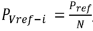
- Step b1, obtaining a total active power reference value Pref at the end where the series voltage source converter valve group is located according to an active power control target of the DC pole, allocating the total active power reference value according to the total number N of voltage source converter valve groups in series, and obtaining an active power reference value PVref-i of the valve group for each operating voltage source converter valve group after evenly allocating the total active power reference value, where
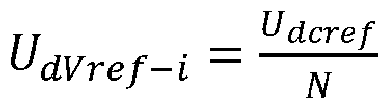
- Step b2, obtaining a total DC voltage reference value Udcrf at the end where the series voltage source converter valve group is located, allocating the total DC voltage reference value according to the total number N of voltage source converter valve groups in series, and obtaining a DC voltage reference value UdVref-i of the valve group for each operating voltage source converter valve group after evenly allocating the total DC voltage reference value, where

- Step b3, obtaining a DC voltage measured value UdV-i of the valve group for each operating valve group in the series voltage source converter valve groups.
- The coordinated control strategy shown in
Figure 4 is adopted, which specifically includes: - Step b4: using ½ of the DC voltage reference value UdVref-i of the valve group for each operating valve group in the series voltage source converter valve groups as a bridge arm DC voltage bias of this valve group;
- Step b5: for each operating valve group of the series voltage source converter valve groups, obtaining an active power compensation amount ΔPV-i of the valve group which has voltage-equalization effect for the valve group, and adding the active power compensation amount ΔPV-i of the valve group and the active power reference value PVref-i of the valve group to obtain a value, and inputting the value into active power control outer loop of the valve group so as to control the active power of this valve group;
- The control of active power of this valve group can be achieved by using the DC bias of the bridge arm voltage of the valve group described in step b4 and the AC voltage reference wave of the valve group described in step b5 to control the bridge arm voltage of the upper and lower bridge arms of each phase of the valve group.
- For the series voltage source converter valve group configured at the active power control terminal of the DC pole, the steps of obtaining an active power compensation amount ΔPV-i of the valve group for each operating valve group, which has voltage-equalization effect for the valve group, including:
- Step c1: calculating a difference between DC voltage reference value UdVref-i of the valve group and the DC voltage measured value UdV-i of the valve group to obtain a DC voltage deviation ΔUdV-i of this valve group;
- Step c2, inputting the DC voltage deviation ΔUdV-i of this valve group into a valve group voltage-equalizing compensator of this valve group, and calculating the DC voltage deviation ΔUdV-i of this valve group in the valve group voltage-equalizing compensator of this valve group by using proportional or integral or proportional plus integral method to obtain the active power compensation amount ΔPV-i of the valve group.
- By superimposing the active power compensation amount ΔPV-i of the valve group on the basis of the active power reference value PVref-i of the valve group, the active power output of the valve group can be dynamically adjusted, which can indirectly achieve the control of the DC voltage of the valve group. The control strategy described above can realize the balanced control of the DC voltage for each operating valve group at the active power control terminal.
- For series voltage source converter valve groups configured at the DC voltage control terminal of DC pole, when the output of the DC voltage control outer loop of one operating valve group is limited by the inner loop current limit caused by the reduced inner loop current limit Idmax , the DC voltage of this valve group deviates from the reference value of the DC voltage of the valve group due to the limited power output. To this end, the current inner loop limit of the valve group will be simultaneously applied to other operating valve groups to maintain the DC voltage equalization.
- For series voltage source converter valve groups configured at the active power control terminal of a DC pole, when the output of the active power control outer loop of one operating valve group is limited by the inner loop current limit caused by the reduced inner loop current limit Idmax, the DC voltage of this valve group deviates from the reference value of the DC voltage of the valve group due to the limited power output. To this end, the current inner loop limit of the valve group will be simultaneously applied to other operating valve groups to maintain the DC voltage equalization.
- The present invention also provides a coordinated control device for series voltage source converter valve groups, as shown in
FIG. 5 , which includes a discrimination unit, an acquisition and distribution unit, a DC voltage control unit and an active power control unit, wherein: - The discrimination unit is configured for determining whether the end where the series voltage source converter valve group is located is a DC voltage control terminal based on the operating status of the DC pole;
- The acquisition and distribution unit is configured for obtaining a total DC voltage reference value Udcref, a total active power reference value Pref, a DC voltage measured value UdV-i of each valve group among operating valve groups etc. based on the operating status of the DC pole, and allocating the total DC voltage reference value Udcref and the total active power reference value Pref according to the total number N of voltage source converter valve groups in series, and obtaining a DC voltage reference value UdVref-i of the valve group and the active power reference value PVref-i of the valve group for each operating voltage source converter valve group after evenly allocating the total DC voltage reference value;
- The DC voltage control unit is configured for controlling the DC voltage of the valve group based on the DC voltage reference value UdVref -i of the valve group and the DC voltage measured value UdV-i of the valve group for each operating valve group in the series voltage source converter valve groups at the DC voltage control terminal of DC pole, and realizing the control for the DC voltage of the DC pole and the DC voltage balance for each operating valve group;
- The active power control unit is configured for controlling the active power of the valve group based on an active power reference value PVref-i of the valve group and an active power compensation amount ΔPV-i of the valve group for each operating valve group in the series voltage source converter valve groups at the active power control terminal of DC pole, and realizing the control for the active power of the DC pole and the DC voltage balance for each operating valve group.
- The DC voltage control unit includes the following subunits:
- a calculation subunit of DC voltage reference value of the valve group for DC voltage control, configured for obtaining a total DC voltage reference value Udcrf at the end where the series voltage source converter valve group is located according to a DC voltage control target of the DC pole, allocating the total DC voltage reference value according to the total number N of voltage source converter valve groups in series, and obtaining a DC voltage reference value UdVref-i of the valve group for each operating voltage source converter valve group after evenly allocating the total DC voltage reference value, where

- a receiving subunit of DC voltage measured value of the valve group for DC voltage control, configured for obtaining a DC voltage measured value UdV-i of the valve group for each operating valve group in the series voltage source converter valve groups;
- a calculation subunit of DC bias of the valve group for DC voltage control, configured for using ½ of the DC voltage reference value UdVref-i of the valve group for each operating valve group in the series voltage source converter valve groups as a bridge arm DC voltage bias of this valve group;
- a control subunit of the valve group for DC voltage control, configured for calculating a difference between the DC voltage reference value UdVref-i of the valve group and the DC voltage measured value UdV-i of the valve group for each operating valve group in the series voltage source converter valve groups, and inputting the difference into a DC voltage control outer loop of this valve group, so as to perform closed-loop control of the DC voltage of this valve group.
- The active power control unit includes the following subunits:
- a calculation subunit of active power reference value of the valve group for active power control, configured for obtaining a total active power reference value Pref at the end where the series voltage source converter valve group is located according to an active power control target of the DC pole, allocating the total active power reference value according to the total number N of voltage source converter valve groups in series, and obtaining an active power reference value PVref-i of the valve group for each operating voltage source converter valve group after evenly allocating the total active power reference value, where

- a calculation subunit of DC voltage reference value of the valve group for active power control, configured for obtaining a total DC voltage reference value Udcrf at the end where the series voltage source converter valve group is located, allocating the total DC voltage reference value according to the total number N of voltage source converter valve groups in series, and obtaining a DC voltage reference value UdVref-i of the valve group after evenly allocating the total DC voltage reference value among operating voltage source converter valve groups, where

- a receiving subunit of DC voltage measured value of the valve group for active power control, configured for obtaining a DC voltage measured value UdV-i of the valve group for each operating valve group in the series voltage source converter valve groups;
- a calculation subunit of DC bias of the valve group for active power control, configured for using ½ of the DC voltage reference value UdVref-i of the valve group for each operating valve group in the series voltage source converter valve groups as a bridge arm DC voltage bias of this valve group;
- a control subunit of valve group for active power control, configured for obtaining an active power compensation amount ΔPV-i of the valve group which has voltage-equalization effect for the valve group for each operating valve group of the series voltage source converter valve groups, and adding the active power compensation amount ΔPV-i of the valve group and the active power reference value PVref-i of the valve group to obtain a value, and inputting the value into active power control outer loop of the valve group so as to control the active power of this valve group.
- In the control subunit of valve group for active power control, specific steps of obtaining an active power compensation amount ΔPV-i of the valve group for each operating valve group, which has voltage-equalization effect for the valve group, include:
- Step c1, calculating a difference between DC voltage reference value UdVref-i of the valve group and the DC voltage measured value UdV-i of the valve group to obtain a DC voltage deviation ΔUdV-i of this valve group;
- Step c2, inputting the DC voltage deviation ΔUdV-i of this valve group into a valve group voltage-equalizing compensator of this valve group, and calculating the DC voltage deviation ΔUdV-i of this valve group in the valve group voltage-equalizing compensator of this valve group by using proportional or integral or proportional plus integral method to obtain the active power compensation amount ΔPV-i of the valve group.
- In the DC voltage control unit, when the output of the DC voltage control outer loop of one operating valve group is limited by a current inner loop limit, the current inner loop limit of the valve group is simultaneously applied to other operating valve groups to maintain the DC voltage balance between each operating valve group.
- In the active power control unit, when the output of the active power control outer loop of one operating valve group is limited by a current inner loop limit, the current inner loop limit of the valve group is simultaneously applied to the other operation valve groups to maintain the DC voltage balance between each operating valve group.
- The above embodiments are only for explaining the technical idea of the present invention, and the scope of protection of the present invention is not limited thereto. Any modification made based on the technical idea according to the technical idea of the present invention falls within the protection scope of the present invention.
Claims (8)
- A coordinated control method for series voltage source converter valve group, the series voltage source converter valve group formed by connecting two or more voltage source converter valve groups in series, the series voltage source converter valve group is able to be configured at a DC voltage control terminal or an active power control terminal of any DC pole in a DC transmission system, characterized in that,the control method including following steps for the series voltage source converter valve group configured at the DC voltage control terminal of the DC pole:Step a1, obtaining a total DC voltage reference value Udcref at the terminal where the series voltage source converter valve group is located according to a DC voltage control target of the DC pole, allocating the total DC voltage reference value Udcref according to a total number N of voltage source converter valve groups in series, and obtaining a DC voltage reference value UdVref-i of a valve group for each operating voltage source converter valve groups after evenly allocating the total DC voltage reference value, where
 Step a2, obtaining a DC voltage measured value UdV-i of the valve group for each operating valve groups in the series voltage source converter valve group;Step a3, using ½ of the DC voltage reference value UdVref-i of the valve group for each operating valve groups in the series voltage source converter valve group as a bridge arm DC voltage bias of this valve group;Step a4: for each operating valve groups of the series voltage source converter valve group, calculating a difference between the DC voltage reference value UdVref-i of the valve group and the DC voltage measured value UdV-i of the valve group, and then inputting the difference into a DC voltage control outer loop of this valve group, so as to perform closed-loop control of the DC voltage of this valve group,the control method including following steps for the series voltage source converter valve group configured at the active power control terminal of the DC pole:Step b1, obtaining a total active power reference value Pref at the terminal where the series voltage source converter valve group is located according to an active power control target of the DC pole, allocating the total active power reference value Pref according to the total number N of voltage source converter valve groups in series, and then obtaining an active power reference value PVref-i of the valve group for each operating voltage source converter valve groups after evenly allocating the total active power reference value, where the
 Step b2, obtaining a total DC voltage reference value Udcref at the terminal where the series voltage source converter valve group is located, allocating the total DC voltage reference value Udcref according to the total number N of voltage source converter valve groups in series, and obtaining a DC voltage reference value UdVref-i of the valve group for each operating voltage source converter valve groups after evenly allocating the total DC voltage reference value Udcref , where
 step b3, obtaining a DC voltage measured value UdV-i of the valve group for each operating valve groups in the series voltage source converter valve group;step b4, using ½ of the DC voltage reference value UdVref-i of the valve group for each operating valve groups in the series voltage source converter valve group as a bridge arm DC voltage bias of this valve group;step b5, for each operating valve groups of the series voltage source converter valve group, obtaining an active power compensation amount ΔPV-i of the valve group which has DC voltage equalization effect for the valve group, and adding the active power compensation amount ΔPV-i of the valve group and the active power reference value PVref-i of the valve group to obtain a value , and then inputting the value into the active power control outer loop of the valve group so as to control the active power of this valve group.
 - The coordinated control method for series voltage source converter valve group according to claim 1, characterized in that: for the series voltage source converter valve group configured at the active power control terminal of DC pole, in the step b5, specific steps of obtaining an active power compensation amount ΔPV-i of the valve group for each operating valve groups, which has DC voltage-equalization effect for the valve group, including:Step c1, calculating a difference between DC voltage reference value UdVref-i of the valve group and the DC voltage measured value UdV-i of the valve group to obtain a DC voltage deviation ΔUdV-i of this valve group;Step c2, inputting the DC voltage deviation ΔUdV-i of this valve group into a valve group voltage-equalizing compensator of this valve group, and calculating the DC voltage deviation ΔUdV-i of this valve group in the valve group voltage-equalizing compensator of this valve group by using proportional or integral or proportional plus integral method to obtain the active power compensation amount ΔPV-i of the valve group.
- The coordinated control method for series voltage source converter valve group according to claim 1, characterized in that, for the series voltage source converter valve group configured at the DC voltage control terminal of DC pole, simultaneously applying the current inner loop limit of one operating valve group to other operating valve groups to maintain the DC voltage balance between each operating valve groups if the output of the DC voltage control outer loop of this operating valve group is limited by a current inner loop limit.
- The coordinated control method for series voltage source converter valve group according to claim 1, characterized in that: for the series voltage source converter valve group configured at the active power control terminal of DC pole, simultaneously applying the current inner loop limit of one operating valve group to other operating valve groups to maintain the DC voltage balance between each operating valve groups if the output of the active power control outer loop of this operating valve group is limited by a current inner loop limit.
- A coordinated control device for series voltage source converter valve group, the series voltage source converter valve group formed by connecting two or more voltage source converter valve groups in series , the series voltage source converter valve group are able to be configured at a DC voltage control terminal or active power control terminal of any DC pole of a DC power transmission system, characterized in that the device comprising: a discrimination unit, an acquisition and distribution unit, a DC voltage control unit and an active power control unit, wherein:the discrimination unit configured for determining whether the terminal where the series voltage source converter valve group is located is a DC voltage control terminal based on the operating status of the DC pole;the acquisition and distribution unit configured for obtaining a total DC voltage reference value Udcref, a total active power reference value Pref, a DC voltage measured value UdV-i of each valve group among operating valve groups etc. based on the operating status of the DC pole, and allocating the total DC voltage reference value Udcrf and the total active power reference value Pref according to the total number N of voltage source converter valve groups in series, and obtaining a DC voltage reference value UdVref-i of a valve group and the active power reference value PVref-i of the valve group for each operating voltage source converter valve groups after evenly allocating the total DC voltage reference value;the DC voltage control unit configured for controlling the DC voltage of the valve group based on the DC voltage reference value UdVref-i of the valve group and the DC voltage measured value UdV-i of the valve group for each operating valve groups in the series voltage source converter valve group at the DC voltage control terminal of DC pole, and realizing the control for the DC voltage of the DC pole and the DC voltage balance for each operating valve groups;the active power control unit configured for controlling the active power of the valve group based on an active power reference value PVref-i of the valve group and an active power compensation amount ΔPV-i of the valve group for each operating valve groups in the series voltage source converter valve group at the active power control terminal of DC pole, and realizing the control for the active power of the DC pole and the DC voltage balance for each operating valve groups;the DC voltage control unit comprising the following subunits:a calculation subunit of DC voltage reference value of the valve group for DC voltage control, configured for obtaining a total DC voltage reference value Udcrf at the terminal where the series voltage source converter valve group is located according to a DC voltage control target of the DC pole, allocating the total DC voltage reference value according to the total number N of voltage source converter valve groups in series, and obtaining a DC voltage reference value UdVref-i of the valve group for each operating voltage source converter valve groups after evenly allocating the total DC voltage reference value, where
 a receiving subunit of DC voltage measured value of the valve group for DC voltage control, configured for obtaining a DC voltage measured value UdV-i of the valve group for each operating valve groups in the series voltage source converter valve group;a calculation subunit of DC bias of the valve group for DC voltage control, configured for using ½ of the DC voltage reference value UdVref-i of the valve group for each operating valve groups in the series voltage source converter valve group as a bridge arm DC voltage bias of this valve group;a control subunit of the valve group for DC voltage control, configured for calculating a difference between the DC voltage reference value UdVref-i of the valve group and the DC voltage measured value UdV-i of the valve group for each operating valve groups in the series voltage source converter valve group, and inputting the difference into a DC voltage control outer loop of this valve group, so as to perform closed-loop control of the DC voltage of this valve group,the active power control unit including the following subunits:a calculation subunit of active power reference value of the valve group for active power control, configured for obtaining a total active power reference value Pref at the terminal where the series voltage source converter valve group is located according to an active power control target of the DC pole, allocating the total active power reference value according to the total number N of voltage source converter valve groups in series, and obtaining an active power reference value PVref-i of the valve group for each operating voltage source converter valve groups after evenly allocating the total active power reference value, where
 a calculation subunit of DC voltage reference value of the valve group for active power control, configured for obtaining a total DC voltage reference value Udcref at the terminal where the series voltage source converter valve group is located, allocating the total DC voltage reference value according to the total number N of voltage source converter valve groups in series, and obtaining a DC voltage reference value UdVref-i of the valve group for each operating voltage source converter valve groups after evenly allocating the total DC voltage reference value, where
 a receiving subunit of DC voltage measured value of the valve group for active power control, configured for obtaining a DC voltage measured value UdV-i of the valve group for each operating valve groups in the series voltage source converter valve group;a calculation subunit of DC bias of the valve group for active power control, configured for using ½ of the DC voltage reference value UdVref-i of the valve group for each operating valve groups in the series voltage source converter valve group as a bridge arm DC voltage bias of this valve group;a control subunit of valve group for active power control, configured for obtaining an active power compensation amount ΔPV-i of the valve group which has DC voltage-equalization effect for the valve group for each operating valve groups of the series voltage source converter valve group, and adding the active power compensation amount ΔPV-i of the valve group and the active power reference value PVref-i of the valve group to obtain a value, and inputting the value into active power control outer loop of the valve group so as to control the active power of this valve group.
 - The coordinated control device for series voltage source converter valve group according to claim 5, further being adapted to, in the control subunit of valve group for active power control, specific steps of obtaining an active power compensation amount ΔPV-i of the valve group for each operating valve groupW, which has DC voltage-equalization effect for the valve group, includes:Step c1, calculating a difference between DC voltage reference value UdVref-i of the valve group and the DC voltage measured value UdV-i of the valve group to obtain a DC voltage deviation ΔUdV-i of this valve group;Step c2, inputting the DC voltage deviation ΔUdV-i of this valve group into a valve group voltage-equalizing compensator of this valve group, and calculating the DC voltage deviation ΔUdV-i of this valve group in the valve group voltage-equalizing compensator of this valve group by using proportional or integral or proportional plus integral method to obtain the active power compensation amount ΔPV-i of the valve group.
- The coordinated control device for series voltage source converter valve group according to claim 5, further being adapted to, in the DC voltage control unit, simultaneously applies the current inner loop limit of one operating valve group to other operating valve groups to maintain the DC voltage balance between each operating valve groups if the output of the DC voltage control outer loop of this operating valve group is limited by a current inner loop limit.
- The coordinated control device for series voltage source converter valve group according to claim 5, further being adapted to, in the active power control unit, simultaneously applies the current inner loop limit of one operating valve group to other operating valve groups to maintain the DC voltage balance between each operating valve groups if the output of the active power control outer loop of this operating valve group is limited by a current inner loop limit.
Applications Claiming Priority (2)
| Application Number | Priority Date | Filing Date | Title |
|---|---|---|---|
| CN201711281866.4A CN107994599B (en) | 2017-12-07 | 2017-12-07 | A coordinated control method and device for a series voltage source commutator valve group |
| PCT/CN2018/117947 WO2019109842A1 (en) | 2017-12-07 | 2018-11-28 | Coordinated control method and device for series voltage source converter valve group |
Publications (3)
| Publication Number | Publication Date |
|---|---|
| EP3723228A1 EP3723228A1 (en) | 2020-10-14 |
| EP3723228A4 EP3723228A4 (en) | 2020-11-25 |
| EP3723228B1 true EP3723228B1 (en) | 2022-08-03 |
Family
ID=62036396
Family Applications (1)
| Application Number | Title | Priority Date | Filing Date |
|---|---|---|---|
| EP18885607.4A Active EP3723228B1 (en) | 2017-12-07 | 2018-11-28 | Coordinated control method and device for series voltage source converter valve group |
Country Status (10)
| Country | Link |
|---|---|
| US (1) | US11146071B2 (en) |
| EP (1) | EP3723228B1 (en) |
| JP (1) | JP6829794B2 (en) |
| KR (1) | KR102136513B1 (en) |
| CN (1) | CN107994599B (en) |
| AU (1) | AU2018378399B2 (en) |
| CA (1) | CA3083838C (en) |
| MX (1) | MX2020005695A (en) |
| RU (1) | RU2735440C1 (en) |
| WO (1) | WO2019109842A1 (en) |
Families Citing this family (4)
| Publication number | Priority date | Publication date | Assignee | Title |
|---|---|---|---|---|
| CN107994599B (en) * | 2017-12-07 | 2020-10-16 | 南京南瑞继保电气有限公司 | A coordinated control method and device for a series voltage source commutator valve group |
| CN113567107B (en) * | 2021-06-15 | 2024-09-13 | 南京南瑞继保电气有限公司 | A cascade type converter valve test system and control method thereof |
| CN115603352B (en) * | 2021-06-28 | 2025-09-05 | 中国南方电网有限责任公司超高压输电公司 | A method for shutting down a multi-terminal hybrid DC transmission system |
| CN115296333B (en) * | 2022-07-20 | 2024-03-26 | 四川大学 | Voltage balance control method based on LCC converter station at the transmission end of UHV DC transmission system |
Family Cites Families (34)
| Publication number | Priority date | Publication date | Assignee | Title |
|---|---|---|---|---|
| WO2009030275A1 (en) * | 2007-09-05 | 2009-03-12 | Abb Technology Ag | Voltage source converter for high voltage direct current power transmission |
| JP5564864B2 (en) * | 2008-12-19 | 2014-08-06 | 日産自動車株式会社 | Secondary battery system |
| WO2010086071A1 (en) * | 2009-01-27 | 2010-08-05 | Abb Research Ltd | Controlling a high-voltage direct-current (hvdc) link |
| RU2435288C2 (en) * | 2009-03-16 | 2011-11-27 | Государственное образовательное учреждение высшего профессионального образования "Иркутский государственный университет путей сообщения" (ИрГУПС (ИрИИТ)) | Method to reduce post-switching oscillations of voltage at electric locomotive current collector and device for its realisation |
| SE0900830L (en) * | 2009-06-18 | 2009-06-29 | Abb Technology Ag | Control of an inverter device to support an alternating current system |
| US8837185B2 (en) * | 2010-02-11 | 2014-09-16 | Siemens Aktiengesellschaft | Control of a modular converter having distributed energy stores with the aid of an observer for the currents and an estimating unit for the intermediate circuit energy |
| US20120119583A1 (en) * | 2010-11-17 | 2012-05-17 | Allfather Lars P | Combined dc power source and battery power converter |
| CN102353897B (en) * | 2011-06-22 | 2014-07-02 | 中国西电电气股份有限公司 | Extra-high voltage converter valve interrupting current test loop and test method thereof |
| JP5894777B2 (en) * | 2011-12-07 | 2016-03-30 | 株式会社日立製作所 | Power converter |
| JP5993675B2 (en) * | 2012-09-14 | 2016-09-14 | 株式会社日立製作所 | Power converter, power conversion system, and control method for power converter |
| CN103269083B (en) * | 2013-04-22 | 2017-02-22 | 国家电网公司 | Multi-terminal high-voltage direct-current power transmission system |
| US9531292B2 (en) * | 2013-06-14 | 2016-12-27 | Abb Technology Ltd | Arrangement, method and computer program product concerned with tapping of power from a DC power line to an AC power line |
| EP2863534B1 (en) * | 2013-10-16 | 2018-09-26 | General Electric Technology GmbH | Voltage source converter |
| CN103675625B (en) * | 2013-12-12 | 2016-09-21 | 国家电网公司 | A kind of converter valve alternating-current voltage resistance test device containing direct current biasing and test method thereof |
| JP6147363B2 (en) * | 2014-01-06 | 2017-06-14 | 三菱電機株式会社 | Power converter |
| KR101512188B1 (en) * | 2014-02-11 | 2015-04-22 | 한국전기연구원 | A driving method of the modular multi-level converter and the apparatus thereof |
| US9602021B2 (en) * | 2014-03-07 | 2017-03-21 | General Electric Company | Hybrid high voltage direct current converter system and method of operating the same |
| EP3148067B1 (en) * | 2014-05-21 | 2020-10-07 | Mitsubishi Electric Corporation | Direct-current power transmission power conversion device and direct-current power transmission power conversion method |
| CN104201910A (en) * | 2014-09-12 | 2014-12-10 | 东南大学 | Sub-module capacitance voltage balance control method for three-phase modular multilevel converter applicable to VSC-HVDC (voltage source converter-high voltage direct current) |
| CN104600738B (en) * | 2015-01-21 | 2017-02-22 | 南京南瑞继保电气有限公司 | Control device for high-voltage DC transmission series valve set |
| CN107580751B (en) * | 2015-05-05 | 2019-10-11 | Abb瑞士股份有限公司 | Voltage source converter with improved operation |
| WO2016207976A1 (en) * | 2015-06-23 | 2016-12-29 | 三菱電機株式会社 | Power conversion device and dc power transmission system |
| CN105162155B (en) * | 2015-08-26 | 2017-10-27 | 浙江大学 | A kind of series hybrid bipolar direct current transmission system with DC Line Fault ride-through capability |
| CN105610180B (en) * | 2016-01-07 | 2019-01-29 | 武汉大学 | A decoupling control method for multi-terminal flexible DC transmission system with DC current feedback |
| EP3446400A1 (en) * | 2016-04-22 | 2019-02-27 | ABB Schweiz AG | Converter arrangement |
| GB2550421A (en) * | 2016-05-20 | 2017-11-22 | General Electric Technology Gmbh | Control of voltage source converters |
| JP6161774B2 (en) * | 2016-08-02 | 2017-07-12 | 三菱電機株式会社 | Power transmission system, power converter and switch |
| US9819188B1 (en) * | 2016-11-22 | 2017-11-14 | Abb Schweiz Ag | Direct current transmission system and method |
| WO2018095405A1 (en) * | 2016-11-25 | 2018-05-31 | 南京南瑞继保电气有限公司 | On-line input and quit control method and device for voltage-source converter unit |
| CN106655239A (en) * | 2017-01-06 | 2017-05-10 | 许继电气股份有限公司 | Combined current converter and internal DC voltage balance control method thereof |
| CN106684901B (en) * | 2017-01-10 | 2019-06-21 | 许继电气股份有限公司 | A combined inverter control method and system for supplying power to a passive system |
| FR3068842B1 (en) * | 2017-07-07 | 2022-03-04 | Inst Supergrid | CONVERTER EQUIPPED WITH AN ENERGY MANAGEMENT MODULE IN ALTERNATIVE PART |
| CN107994599B (en) * | 2017-12-07 | 2020-10-16 | 南京南瑞继保电气有限公司 | A coordinated control method and device for a series voltage source commutator valve group |
| CN107769241B (en) * | 2017-12-07 | 2020-07-28 | 南京南瑞继保电气有限公司 | A method and device for controlling voltage and current in a direct current transmission system |
-
2017
- 2017-12-07 CN CN201711281866.4A patent/CN107994599B/en active Active
-
2018
- 2018-11-28 AU AU2018378399A patent/AU2018378399B2/en not_active Ceased
- 2018-11-28 JP JP2020528153A patent/JP6829794B2/en not_active Expired - Fee Related
- 2018-11-28 RU RU2020122249A patent/RU2735440C1/en active
- 2018-11-28 KR KR1020207011047A patent/KR102136513B1/en not_active Expired - Fee Related
- 2018-11-28 CA CA3083838A patent/CA3083838C/en active Active
- 2018-11-28 MX MX2020005695A patent/MX2020005695A/en unknown
- 2018-11-28 WO PCT/CN2018/117947 patent/WO2019109842A1/en not_active Ceased
- 2018-11-28 EP EP18885607.4A patent/EP3723228B1/en active Active
- 2018-11-28 US US16/770,458 patent/US11146071B2/en not_active Expired - Fee Related
Also Published As
| Publication number | Publication date |
|---|---|
| US20210126462A1 (en) | 2021-04-29 |
| RU2735440C1 (en) | 2020-11-02 |
| CN107994599A (en) | 2018-05-04 |
| MX2020005695A (en) | 2020-08-20 |
| AU2018378399B2 (en) | 2021-03-04 |
| EP3723228A4 (en) | 2020-11-25 |
| JP2021505108A (en) | 2021-02-15 |
| EP3723228A1 (en) | 2020-10-14 |
| WO2019109842A1 (en) | 2019-06-13 |
| US11146071B2 (en) | 2021-10-12 |
| CN107994599B (en) | 2020-10-16 |
| AU2018378399A1 (en) | 2020-06-18 |
| CA3083838A1 (en) | 2019-06-13 |
| JP6829794B2 (en) | 2021-02-10 |
| KR20200044136A (en) | 2020-04-28 |
| CA3083838C (en) | 2021-02-16 |
| BR112020011124A2 (en) | 2020-11-17 |
| KR102136513B1 (en) | 2020-07-21 |
Similar Documents
| Publication | Publication Date | Title |
|---|---|---|
| EP3681006B1 (en) | Voltage and current control method and device for direct-current power transmission system | |
| CN112086995B (en) | Control strategy suitable for LCC-MMC hybrid cascade converter station parallel MMC unit | |
| EP3723228B1 (en) | Coordinated control method and device for series voltage source converter valve group | |
| CN103441510B (en) | A reactive power optimization method for regional power grids including flexible direct current transmission systems | |
| CN107276083B (en) | A kind of alternating current-direct current power grid progress control method towards energy internet | |
| CN110829476A (en) | Balanced control strategy for unbalanced current among multiple MMC converters in extra-high voltage hybrid cascaded direct current transmission system | |
| CN109274113A (en) | Nonlinear droop control method for hybrid multi-terminal direct current transmission system | |
| CN107968410A (en) | A kind of method for improving AC-DC hybrid power grid dc power hoisting power | |
| CN107134800B (en) | Bipolar VSC passive control method and device for a direct current transmission system | |
| CN109802424B (en) | Hybrid direct current transmission system converter input coordination method and device | |
| CN114123288B (en) | Method for determining optimal reactive power exchange quantity between converter station and alternating current power grid | |
| CN104993499B (en) | Method and system for controlling reactive output power of combined back-to-back direct current transmission system | |
| CN107332290A (en) | A kind of region load transfer method based on DC line | |
| CN106329560A (en) | A power boosting method during AC faults on the hybrid DC rectifier side | |
| CN111628508A (en) | Coordinated control method of camera and SVC for suppressing HVDC transient overvoltage | |
| CN107612013B (en) | Direct-current power grid voltage range control method | |
| CN112886627B (en) | Method for improving power transmission capability of MMC power supply passive network | |
| CN119231614B (en) | A method and device for island starting of ultra-high voltage flexible direct current transmission system | |
| CN112350360A (en) | PV curve solving method and system for receiving-end communication system | |
| CN121602512A (en) | Control methods and systems for grid-type flexible DC converters | |
| CN103731019B (en) | An Overmodulation Method for Modular Multilevel Converter Station | |
| CN113949088A (en) | Alternating current and direct current converting system for power plant and factory | |
| BR112020011124B1 (en) | COORDINATED CONTROL METHOD AND DEVICE FOR GROUP OF SERIES VOLTAGE SOURCE CONVERTER VALVES |
Legal Events
| Date | Code | Title | Description |
|---|---|---|---|
| STAA | Information on the status of an ep patent application or granted ep patent |
Free format text: STATUS: THE INTERNATIONAL PUBLICATION HAS BEEN MADE |
|
| PUAI | Public reference made under article 153(3) epc to a published international application that has entered the european phase |
Free format text: ORIGINAL CODE: 0009012 |
|
| STAA | Information on the status of an ep patent application or granted ep patent |
Free format text: STATUS: REQUEST FOR EXAMINATION WAS MADE |
|
| 17P | Request for examination filed |
Effective date: 20200528 |
|
| AK | Designated contracting states |
Kind code of ref document: A1 Designated state(s): AL AT BE BG CH CY CZ DE DK EE ES FI FR GB GR HR HU IE IS IT LI LT LU LV MC MK MT NL NO PL PT RO RS SE SI SK SM TR |
|
| AX | Request for extension of the european patent |
Extension state: BA ME |
|
| A4 | Supplementary search report drawn up and despatched |
Effective date: 20201022 |
|
| RIC1 | Information provided on ipc code assigned before grant |
Ipc: H02J 3/36 20060101AFI20201016BHEP |
|
| DAV | Request for validation of the european patent (deleted) | ||
| DAX | Request for extension of the european patent (deleted) | ||
| STAA | Information on the status of an ep patent application or granted ep patent |
Free format text: STATUS: EXAMINATION IS IN PROGRESS |
|
| 17Q | First examination report despatched |
Effective date: 20210726 |
|
| GRAP | Despatch of communication of intention to grant a patent |
Free format text: ORIGINAL CODE: EPIDOSNIGR1 |
|
| STAA | Information on the status of an ep patent application or granted ep patent |
Free format text: STATUS: GRANT OF PATENT IS INTENDED |
|
| INTG | Intention to grant announced |
Effective date: 20220321 |
|
| GRAS | Grant fee paid |
Free format text: ORIGINAL CODE: EPIDOSNIGR3 |
|
| GRAA | (expected) grant |
Free format text: ORIGINAL CODE: 0009210 |
|
| STAA | Information on the status of an ep patent application or granted ep patent |
Free format text: STATUS: THE PATENT HAS BEEN GRANTED |
|
| AK | Designated contracting states |
Kind code of ref document: B1 Designated state(s): AL AT BE BG CH CY CZ DE DK EE ES FI FR GB GR HR HU IE IS IT LI LT LU LV MC MK MT NL NO PL PT RO RS SE SI SK SM TR |
|
| REG | Reference to a national code |
Ref country code: AT Ref legal event code: REF Ref document number: 1509531 Country of ref document: AT Kind code of ref document: T Effective date: 20220815 Ref country code: CH Ref legal event code: EP |
|
| REG | Reference to a national code |
Ref country code: DE Ref legal event code: R096 Ref document number: 602018038931 Country of ref document: DE |
|
| REG | Reference to a national code |
Ref country code: IE Ref legal event code: FG4D |
|
| REG | Reference to a national code |
Ref country code: LT Ref legal event code: MG9D |
|
| REG | Reference to a national code |
Ref country code: NL Ref legal event code: MP Effective date: 20220803 |
|
| PG25 | Lapsed in a contracting state [announced via postgrant information from national office to epo] |
Ref country code: SE Free format text: LAPSE BECAUSE OF FAILURE TO SUBMIT A TRANSLATION OF THE DESCRIPTION OR TO PAY THE FEE WITHIN THE PRESCRIBED TIME-LIMIT Effective date: 20220803 Ref country code: RS Free format text: LAPSE BECAUSE OF FAILURE TO SUBMIT A TRANSLATION OF THE DESCRIPTION OR TO PAY THE FEE WITHIN THE PRESCRIBED TIME-LIMIT Effective date: 20220803 Ref country code: PT Free format text: LAPSE BECAUSE OF FAILURE TO SUBMIT A TRANSLATION OF THE DESCRIPTION OR TO PAY THE FEE WITHIN THE PRESCRIBED TIME-LIMIT Effective date: 20221205 Ref country code: NO Free format text: LAPSE BECAUSE OF FAILURE TO SUBMIT A TRANSLATION OF THE DESCRIPTION OR TO PAY THE FEE WITHIN THE PRESCRIBED TIME-LIMIT Effective date: 20221103 Ref country code: NL Free format text: LAPSE BECAUSE OF FAILURE TO SUBMIT A TRANSLATION OF THE DESCRIPTION OR TO PAY THE FEE WITHIN THE PRESCRIBED TIME-LIMIT Effective date: 20220803 Ref country code: LV Free format text: LAPSE BECAUSE OF FAILURE TO SUBMIT A TRANSLATION OF THE DESCRIPTION OR TO PAY THE FEE WITHIN THE PRESCRIBED TIME-LIMIT Effective date: 20220803 Ref country code: LT Free format text: LAPSE BECAUSE OF FAILURE TO SUBMIT A TRANSLATION OF THE DESCRIPTION OR TO PAY THE FEE WITHIN THE PRESCRIBED TIME-LIMIT Effective date: 20220803 Ref country code: FI Free format text: LAPSE BECAUSE OF FAILURE TO SUBMIT A TRANSLATION OF THE DESCRIPTION OR TO PAY THE FEE WITHIN THE PRESCRIBED TIME-LIMIT Effective date: 20220803 Ref country code: ES Free format text: LAPSE BECAUSE OF FAILURE TO SUBMIT A TRANSLATION OF THE DESCRIPTION OR TO PAY THE FEE WITHIN THE PRESCRIBED TIME-LIMIT Effective date: 20220803 |
|
| REG | Reference to a national code |
Ref country code: AT Ref legal event code: MK05 Ref document number: 1509531 Country of ref document: AT Kind code of ref document: T Effective date: 20220803 |
|
| PG25 | Lapsed in a contracting state [announced via postgrant information from national office to epo] |
Ref country code: PL Free format text: LAPSE BECAUSE OF FAILURE TO SUBMIT A TRANSLATION OF THE DESCRIPTION OR TO PAY THE FEE WITHIN THE PRESCRIBED TIME-LIMIT Effective date: 20220803 Ref country code: IS Free format text: LAPSE BECAUSE OF FAILURE TO SUBMIT A TRANSLATION OF THE DESCRIPTION OR TO PAY THE FEE WITHIN THE PRESCRIBED TIME-LIMIT Effective date: 20221203 Ref country code: HR Free format text: LAPSE BECAUSE OF FAILURE TO SUBMIT A TRANSLATION OF THE DESCRIPTION OR TO PAY THE FEE WITHIN THE PRESCRIBED TIME-LIMIT Effective date: 20220803 Ref country code: GR Free format text: LAPSE BECAUSE OF FAILURE TO SUBMIT A TRANSLATION OF THE DESCRIPTION OR TO PAY THE FEE WITHIN THE PRESCRIBED TIME-LIMIT Effective date: 20221104 |
|
| PG25 | Lapsed in a contracting state [announced via postgrant information from national office to epo] |
Ref country code: SM Free format text: LAPSE BECAUSE OF FAILURE TO SUBMIT A TRANSLATION OF THE DESCRIPTION OR TO PAY THE FEE WITHIN THE PRESCRIBED TIME-LIMIT Effective date: 20220803 Ref country code: RO Free format text: LAPSE BECAUSE OF FAILURE TO SUBMIT A TRANSLATION OF THE DESCRIPTION OR TO PAY THE FEE WITHIN THE PRESCRIBED TIME-LIMIT Effective date: 20220803 Ref country code: DK Free format text: LAPSE BECAUSE OF FAILURE TO SUBMIT A TRANSLATION OF THE DESCRIPTION OR TO PAY THE FEE WITHIN THE PRESCRIBED TIME-LIMIT Effective date: 20220803 Ref country code: CZ Free format text: LAPSE BECAUSE OF FAILURE TO SUBMIT A TRANSLATION OF THE DESCRIPTION OR TO PAY THE FEE WITHIN THE PRESCRIBED TIME-LIMIT Effective date: 20220803 Ref country code: AT Free format text: LAPSE BECAUSE OF FAILURE TO SUBMIT A TRANSLATION OF THE DESCRIPTION OR TO PAY THE FEE WITHIN THE PRESCRIBED TIME-LIMIT Effective date: 20220803 |
|
| REG | Reference to a national code |
Ref country code: DE Ref legal event code: R097 Ref document number: 602018038931 Country of ref document: DE |
|
| PG25 | Lapsed in a contracting state [announced via postgrant information from national office to epo] |
Ref country code: SK Free format text: LAPSE BECAUSE OF FAILURE TO SUBMIT A TRANSLATION OF THE DESCRIPTION OR TO PAY THE FEE WITHIN THE PRESCRIBED TIME-LIMIT Effective date: 20220803 Ref country code: EE Free format text: LAPSE BECAUSE OF FAILURE TO SUBMIT A TRANSLATION OF THE DESCRIPTION OR TO PAY THE FEE WITHIN THE PRESCRIBED TIME-LIMIT Effective date: 20220803 |
|
| PLBE | No opposition filed within time limit |
Free format text: ORIGINAL CODE: 0009261 |
|
| STAA | Information on the status of an ep patent application or granted ep patent |
Free format text: STATUS: NO OPPOSITION FILED WITHIN TIME LIMIT |
|
| PG25 | Lapsed in a contracting state [announced via postgrant information from national office to epo] |
Ref country code: MC Free format text: LAPSE BECAUSE OF FAILURE TO SUBMIT A TRANSLATION OF THE DESCRIPTION OR TO PAY THE FEE WITHIN THE PRESCRIBED TIME-LIMIT Effective date: 20220803 Ref country code: AL Free format text: LAPSE BECAUSE OF FAILURE TO SUBMIT A TRANSLATION OF THE DESCRIPTION OR TO PAY THE FEE WITHIN THE PRESCRIBED TIME-LIMIT Effective date: 20220803 |
|
| REG | Reference to a national code |
Ref country code: CH Ref legal event code: PL |
|
| 26N | No opposition filed |
Effective date: 20230504 |
|
| REG | Reference to a national code |
Ref country code: BE Ref legal event code: MM Effective date: 20221130 |
|
| PG25 | Lapsed in a contracting state [announced via postgrant information from national office to epo] |
Ref country code: LI Free format text: LAPSE BECAUSE OF NON-PAYMENT OF DUE FEES Effective date: 20221130 Ref country code: CH Free format text: LAPSE BECAUSE OF NON-PAYMENT OF DUE FEES Effective date: 20221130 |
|
| PG25 | Lapsed in a contracting state [announced via postgrant information from national office to epo] |
Ref country code: SI Free format text: LAPSE BECAUSE OF FAILURE TO SUBMIT A TRANSLATION OF THE DESCRIPTION OR TO PAY THE FEE WITHIN THE PRESCRIBED TIME-LIMIT Effective date: 20220803 Ref country code: LU Free format text: LAPSE BECAUSE OF NON-PAYMENT OF DUE FEES Effective date: 20221128 |
|
| PG25 | Lapsed in a contracting state [announced via postgrant information from national office to epo] |
Ref country code: IE Free format text: LAPSE BECAUSE OF NON-PAYMENT OF DUE FEES Effective date: 20221128 |
|
| PG25 | Lapsed in a contracting state [announced via postgrant information from national office to epo] |
Ref country code: FR Free format text: LAPSE BECAUSE OF NON-PAYMENT OF DUE FEES Effective date: 20221130 Ref country code: BE Free format text: LAPSE BECAUSE OF NON-PAYMENT OF DUE FEES Effective date: 20221130 |
|
| PG25 | Lapsed in a contracting state [announced via postgrant information from national office to epo] |
Ref country code: CY Free format text: LAPSE BECAUSE OF FAILURE TO SUBMIT A TRANSLATION OF THE DESCRIPTION OR TO PAY THE FEE WITHIN THE PRESCRIBED TIME-LIMIT Effective date: 20220803 |
|
| PG25 | Lapsed in a contracting state [announced via postgrant information from national office to epo] |
Ref country code: MK Free format text: LAPSE BECAUSE OF FAILURE TO SUBMIT A TRANSLATION OF THE DESCRIPTION OR TO PAY THE FEE WITHIN THE PRESCRIBED TIME-LIMIT Effective date: 20220803 Ref country code: IT Free format text: LAPSE BECAUSE OF FAILURE TO SUBMIT A TRANSLATION OF THE DESCRIPTION OR TO PAY THE FEE WITHIN THE PRESCRIBED TIME-LIMIT Effective date: 20220803 Ref country code: HU Free format text: LAPSE BECAUSE OF FAILURE TO SUBMIT A TRANSLATION OF THE DESCRIPTION OR TO PAY THE FEE WITHIN THE PRESCRIBED TIME-LIMIT; INVALID AB INITIO Effective date: 20181128 |
|
| PG25 | Lapsed in a contracting state [announced via postgrant information from national office to epo] |
Ref country code: BG Free format text: LAPSE BECAUSE OF FAILURE TO SUBMIT A TRANSLATION OF THE DESCRIPTION OR TO PAY THE FEE WITHIN THE PRESCRIBED TIME-LIMIT Effective date: 20220803 |
|
| PG25 | Lapsed in a contracting state [announced via postgrant information from national office to epo] |
Ref country code: MT Free format text: LAPSE BECAUSE OF FAILURE TO SUBMIT A TRANSLATION OF THE DESCRIPTION OR TO PAY THE FEE WITHIN THE PRESCRIBED TIME-LIMIT Effective date: 20220803 |
|
| PG25 | Lapsed in a contracting state [announced via postgrant information from national office to epo] |
Ref country code: TR Free format text: LAPSE BECAUSE OF FAILURE TO SUBMIT A TRANSLATION OF THE DESCRIPTION OR TO PAY THE FEE WITHIN THE PRESCRIBED TIME-LIMIT Effective date: 20220803 |
|
| PGFP | Annual fee paid to national office [announced via postgrant information from national office to epo] |
Ref country code: DE Payment date: 20251117 Year of fee payment: 8 |
|
| PGFP | Annual fee paid to national office [announced via postgrant information from national office to epo] |
Ref country code: GB Payment date: 20251126 Year of fee payment: 8 |