EP3723211A1 - Connector - Google Patents
Connector Download PDFInfo
- Publication number
- EP3723211A1 EP3723211A1 EP18885254.5A EP18885254A EP3723211A1 EP 3723211 A1 EP3723211 A1 EP 3723211A1 EP 18885254 A EP18885254 A EP 18885254A EP 3723211 A1 EP3723211 A1 EP 3723211A1
- Authority
- EP
- European Patent Office
- Prior art keywords
- wall portion
- main body
- connector
- base wall
- body case
- Prior art date
- Legal status (The legal status is an assumption and is not a legal conclusion. Google has not performed a legal analysis and makes no representation as to the accuracy of the status listed.)
- Withdrawn
Links
- 238000003780 insertion Methods 0.000 claims abstract description 74
- 230000037431 insertion Effects 0.000 claims abstract description 74
- 239000007788 liquid Substances 0.000 claims abstract description 21
- 238000007599 discharging Methods 0.000 claims description 2
- 238000012856 packing Methods 0.000 description 14
- 230000002093 peripheral effect Effects 0.000 description 11
- XLYOFNOQVPJJNP-UHFFFAOYSA-N water Substances O XLYOFNOQVPJJNP-UHFFFAOYSA-N 0.000 description 9
- 239000004925 Acrylic resin Substances 0.000 description 4
- 230000000903 blocking effect Effects 0.000 description 4
- 239000013013 elastic material Substances 0.000 description 4
- 229920002050 silicone resin Polymers 0.000 description 4
- 230000000149 penetrating effect Effects 0.000 description 3
- 230000015572 biosynthetic process Effects 0.000 description 1
- 230000000694 effects Effects 0.000 description 1
Images







Classifications
-
- H—ELECTRICITY
- H01—ELECTRIC ELEMENTS
- H01R—ELECTRICALLY-CONDUCTIVE CONNECTIONS; STRUCTURAL ASSOCIATIONS OF A PLURALITY OF MUTUALLY-INSULATED ELECTRICAL CONNECTING ELEMENTS; COUPLING DEVICES; CURRENT COLLECTORS
- H01R13/00—Details of coupling devices of the kinds covered by groups H01R12/70 or H01R24/00 - H01R33/00
- H01R13/46—Bases; Cases
- H01R13/52—Dustproof, splashproof, drip-proof, waterproof, or flameproof cases
- H01R13/5205—Sealing means between cable and housing, e.g. grommet
- H01R13/5208—Sealing means between cable and housing, e.g. grommet having at least two cable receiving openings
-
- H—ELECTRICITY
- H01—ELECTRIC ELEMENTS
- H01R—ELECTRICALLY-CONDUCTIVE CONNECTIONS; STRUCTURAL ASSOCIATIONS OF A PLURALITY OF MUTUALLY-INSULATED ELECTRICAL CONNECTING ELEMENTS; COUPLING DEVICES; CURRENT COLLECTORS
- H01R13/00—Details of coupling devices of the kinds covered by groups H01R12/70 or H01R24/00 - H01R33/00
- H01R13/46—Bases; Cases
- H01R13/502—Bases; Cases composed of different pieces
- H01R13/512—Bases; Cases composed of different pieces assembled by screw or screws
-
- H—ELECTRICITY
- H01—ELECTRIC ELEMENTS
- H01R—ELECTRICALLY-CONDUCTIVE CONNECTIONS; STRUCTURAL ASSOCIATIONS OF A PLURALITY OF MUTUALLY-INSULATED ELECTRICAL CONNECTING ELEMENTS; COUPLING DEVICES; CURRENT COLLECTORS
- H01R13/00—Details of coupling devices of the kinds covered by groups H01R12/70 or H01R24/00 - H01R33/00
- H01R13/46—Bases; Cases
- H01R13/516—Means for holding or embracing insulating body, e.g. casing, hoods
-
- H—ELECTRICITY
- H01—ELECTRIC ELEMENTS
- H01R—ELECTRICALLY-CONDUCTIVE CONNECTIONS; STRUCTURAL ASSOCIATIONS OF A PLURALITY OF MUTUALLY-INSULATED ELECTRICAL CONNECTING ELEMENTS; COUPLING DEVICES; CURRENT COLLECTORS
- H01R13/00—Details of coupling devices of the kinds covered by groups H01R12/70 or H01R24/00 - H01R33/00
- H01R13/46—Bases; Cases
- H01R13/52—Dustproof, splashproof, drip-proof, waterproof, or flameproof cases
- H01R13/5202—Sealing means between parts of housing or between housing part and a wall, e.g. sealing rings
-
- H—ELECTRICITY
- H01—ELECTRIC ELEMENTS
- H01R—ELECTRICALLY-CONDUCTIVE CONNECTIONS; STRUCTURAL ASSOCIATIONS OF A PLURALITY OF MUTUALLY-INSULATED ELECTRICAL CONNECTING ELEMENTS; COUPLING DEVICES; CURRENT COLLECTORS
- H01R13/00—Details of coupling devices of the kinds covered by groups H01R12/70 or H01R24/00 - H01R33/00
- H01R13/46—Bases; Cases
- H01R13/52—Dustproof, splashproof, drip-proof, waterproof, or flameproof cases
- H01R13/521—Sealing between contact members and housing, e.g. sealing insert
-
- H—ELECTRICITY
- H01—ELECTRIC ELEMENTS
- H01R—ELECTRICALLY-CONDUCTIVE CONNECTIONS; STRUCTURAL ASSOCIATIONS OF A PLURALITY OF MUTUALLY-INSULATED ELECTRICAL CONNECTING ELEMENTS; COUPLING DEVICES; CURRENT COLLECTORS
- H01R13/00—Details of coupling devices of the kinds covered by groups H01R12/70 or H01R24/00 - H01R33/00
- H01R13/46—Bases; Cases
- H01R13/52—Dustproof, splashproof, drip-proof, waterproof, or flameproof cases
- H01R13/5227—Dustproof, splashproof, drip-proof, waterproof, or flameproof cases with evacuation of penetrating liquids
-
- H—ELECTRICITY
- H01—ELECTRIC ELEMENTS
- H01R—ELECTRICALLY-CONDUCTIVE CONNECTIONS; STRUCTURAL ASSOCIATIONS OF A PLURALITY OF MUTUALLY-INSULATED ELECTRICAL CONNECTING ELEMENTS; COUPLING DEVICES; CURRENT COLLECTORS
- H01R2201/00—Connectors or connections adapted for particular applications
- H01R2201/26—Connectors or connections adapted for particular applications for vehicles
-
- H—ELECTRICITY
- H01—ELECTRIC ELEMENTS
- H01R—ELECTRICALLY-CONDUCTIVE CONNECTIONS; STRUCTURAL ASSOCIATIONS OF A PLURALITY OF MUTUALLY-INSULATED ELECTRICAL CONNECTING ELEMENTS; COUPLING DEVICES; CURRENT COLLECTORS
- H01R24/00—Two-part coupling devices, or either of their cooperating parts, characterised by their overall structure
- H01R24/20—Coupling parts carrying sockets, clips or analogous contacts and secured only to wire or cable
Definitions
- the present invention relates to a connector.
- a connector used for charging an electric machine driven by electric power such as an electric vehicle there is a connector including a housing and a cable inserted into the housing, as in Patent Documents 1 and 2, for example.
- the housing has a fitting portion (insertion portion) that fits into a power reception connector (electric socket) of the electric machine.
- Patent Document 1 and Patent Document 2 have an insufficient waterproof structure and have been required to prevent water from entering the housing.
- An aspect of the present invention has been made in view of the above circumstances and provides a connector that can prevent water from entering inside.
- a first aspect of the present invention is a connector connectable to a reception side connector of the electric machine, the connector including, a main body case formed in a tubular shape and comprising a front end opening portion that opens at a front end portion in a central axis direction of the tubular shape, a front housing including a base wall portion closing the front end opening portion of the main body case and a side wall portion protruding forward from the base wall portion and fitted to the reception side connector, and a cable unit comprising a cable inserted into the main body case and a terminal provided at a distal end of the cable and protruding forward of the base wall portion.
- the base wall portion of the front housing has a cable unit insertion hole through which the cable unit is inserted and the cable unit is fixed to the base wall portion in a state where liquid tightness with respect to the unit insertion hole is secured.
- the connector in the connector according to the first aspect, preferably further includes an outer case that accommodates the main body case.
- the main body case preferably has a fastener insertion hole that is a through hole and is preferably fixed to the front housing by a body case fastener inserted into the fastener insertion hole.
- the outer case is preferably fixed to the front housing by an outer case fastener.
- the connector in the connector according to any one of the first to fourth aspects, preferably further includes a fixing member fixing the cable unit to a rear surface of the base wall portion.
- the main body case is preferably formed integrally.
- a liquid discharge port discharging the liquid in the outer case is preferably formed in the outer case.
- the fixing structure at the front portion of the connector can be simplified as compared with the structure having the terminal plate. Therefore, waterproofness can be ensured despite the fact that force is easily applied to the front housing by fitting with the reception side connector.
- the outer case for housing the main body case by providing the outer case for housing the main body case, the fastener insertion hole for fixing the main body case and the front housing can be surrounded by the outer case. Therefore, the waterproofness of the fixing structure between the main body case and the front housing can be improved.
- the mechanical strength of the connector can be increased by the double wall structure of the main body case and the outer case.
- FIGS. 1-15 an embodiment of a connector according to the present invention will be described with reference to FIGS. 1-15 .
- the connector A of the present embodiment is provided in a charging device such as a charging stand that supplies power to an electric vehicle (electric machine) and can be connected to the reception side connector (not shown) provided in the electric vehicle when power is supplied (during charging).
- the connector A is a power supply connector for supplying power to the electric machine.
- the positive direction of the Y axis in each drawing may be referred to as the front, and the negative direction of the Y axis may be referred to as the rear.
- the positive direction of the X axis may be referred to as the upper, and the negative direction of the X axis may be referred to as the lower.
- the positive direction of the X axis may be referred to as a height direction (upward).
- the Z-axis direction may be referred to as a width direction.
- the connector A includes a main body case 1, a front housing 2, a power supply cable unit (cable unit) 3, an outer case 4, a protection cover 5, and a cable fixing member 6.
- the main body case 1 includes a main portion 11 and a rear extension portion 12 formed so as to be continuous with the main portion 11.
- the main portion 11 is a tubular shape having a front end opening portion 11a that opens at an end portion at a front side (front end portion) in the direction of the center axis L1 (Y-axis direction).
- the shape of the cross section of the main portion 11 orthogonal to the direction of the center axis L1 may be a rectangular shape, and for example, a rectangular shape in which four corners are formed in an arc shape.
- the front end opening 11a may be a rectangular shape, for example, a rectangular shape in which four corners are formed in an arc shape.
- An annular groove 13 (see FIG. 13 ) is formed on the outer peripheral surface of the main portion 11 at a position near the front end opening 11a.
- the annular groove 13 is formed in a direction around the central axis L1.
- the rear extension portion 12 has a tubular shape extending from the rear end portion of the main portion 11 in a direction inclined in the direction of the central axis L1 (Y-axis direction).
- the internal space of the rear extension portion 12 communicates with the internal space of the main portion 11.
- groove portions 14 are formed on both sides of the main body case 1 along the front-rear direction.
- a fastener insertion hole 20 into which the body case fastener 72 is inserted is formed in the end plate 15 formed at the front end of the groove 14.
- the fastener insertion hole 20 is a through hole formed through the end plate portion 15.
- the main body case 1 is preferably formed integrally. Thereby, the waterproofness of the main body case 1 can be improved.
- the front housing 2 includes a base wall portion 21, a first side wall portion 22, a second side wall portion 23, a terminal tube portion 24, a holding tube portion 25, and a peripheral wall portion 26.
- the base wall portion 21 may have a rectangular shape, for example, a rectangular plate shape in which four corners are formed in an arc shape. As shown in FIG. 2 , the base wall portion 21 is installed so as to cover the front end opening portion 11a of the main portion 11.
- the base wall portion 21 includes a cable unit insertion hole 16 through which the power supply cable unit 3 is inserted, a fastener insertion hole 17 into which the external case fastener 71 is inserted, a fastener insertion hole 18 into which the main body case fastener 72 is inserted, and a fastener insertion hole 19 into which the cable fixing member fasteners 73 and 74 are inserted.
- the cable unit insertion hole 16 is formed to penetrate the base wall portion 21 in the thickness direction.
- the cable unit insertion hole 16 has the first to fifth cable unit insertion holes 16A, 16B, 16C, 16D, and 16E.
- the fastener insertion hole 17 has fastener insertion holes 17A and 17B. External case fasteners 71 and 71 are inserted into the fastener insertion holes 17A and 17B, respectively.
- the fastener insertion holes 17A and 17B are open to the front surface 21a and are formed without penetrating the base wall portion 21 in the thickness direction.
- the fastener insertion holes 17A and 17B preferably have internal-threads formed on each inner surface.
- the fastener insertion hole 17A is formed at a position near one side edge 21b of the base wall portion 21.
- the fastener insertion hole 17B is formed at a position near the other side edge 21b of the base wall portion 21.
- the fastener insertion hole 18 has fastener insertion holes 18A and 18B.
- the main body case fasteners 72 and 72 are inserted into the fastener insertion holes 18A and 18B, respectively.
- the fastener insertion holes 18A and 18B are formed in columnar bodies 27 and 27 formed to protrude rearward from the rear surface 21b of the base wall portion 21.
- the fastener insertion holes 18A and 18B are open to the protrusion end surfaces 27a and 27a of the columnar bodies 27 and 27, and are formed without penetrating the base wall portion 21 in the thickness direction. That is, the depth of the fastener insertion holes 18A and 18B is such that the fastener insertion holes 18A and 18B do not reach the front surface 21a of the base wall portion 21.
- the fastener insertion holes 18A and 18B preferably have internal-threads formed on each inner surface.
- the fastener insertion hole 19 includes a fastener insertion hole 19A through which the first cable fixing member fastener 73 is inserted and a fastener insertion hole 19B through which the second cable fixing member fastener 74 is inserted.
- the fastener insertion holes 19A and 19B are respectively formed in columnar bodies 28 and 29 formed to protrude rearward from the rear surface 21b of the base wall portion 21.
- the fastener insertion holes 19A and 19B are opened respectively at the protrusion end surfaces 28a and 29a of the columnar bodies 28 and 29, and are formed without penetrating the base wall portion 21 in the thickness direction. That is, a depth of each of the fastener insertion holes 19A and 19B are such that they do not reach the front surface 21a of the base wall portion 21.
- the fastener insertion holes 19A and 19B preferably have internal-threads formed on the inner surface.
- the first side wall portion 22 has substantially a tubular shape and is formed to protrude forward from the front surface 21a of the base wall portion 21.
- the first side wall portion 22 is formed so as to collectively surround the first cable unit insertion hole 16A, the fourth cable unit insertion hole 16D, and the fifth cable unit insertion hole 16E.
- the second side wall portion 23 has an elliptical tubular shape and is formed to protrude forward from the front surface 21a of the base wall portion 21.
- the second side wall portion 23 is formed at a position lower than the first side wall portion 22.
- the second side wall portion 23 is formed so as to collectively surround the second cable unit insertion hole 16B and the third cable unit insertion hole 16C.
- the first side wall portion 22 and the second side wall portion 23 are formed, for example, so as to be insertable into a shell of a reception side connector (not shown).
- the first side wall portion 22 and the second side wall portion 23 are formed integrally with the base wall portion 21.
- the terminal tube portion 24 includes the first to fifth terminal tube portions 24A, 24B, 24C, 24D, and 24E.
- the first terminal tube portion 24A has a tubular shape and is formed to protrude forward from the front surface 21a of the base wall portion 21.
- the first terminal tube portion 24A is formed so as to surround the first cable unit insertion hole 16A.
- the first terminal tube portion 24A is formed in the first side wall portion 22.
- the second terminal tube portion 24B and the third terminal tube portion 24C have a tubular shape and are formed to protrude forward from the front surface 21a of the base wall portion 21, respectively.
- the second terminal tube portion 24B is formed so as to surround the second cable unit insertion hole 16B.
- the third terminal tube portion 24C is formed so as to surround the third cable unit insertion hole 16C.
- the second terminal tube portion 24B and the third terminal tube portion 24C are formed in the second side wall portion 23 aligning in the Z-axis direction.
- the fourth terminal tube portion 24D and the fifth terminal tube portion 24E have a tubular shape and are formed to protrude forward from the front surface 21a of the base wall portion 21, respectively.
- the fourth terminal tube portion 24D is formed so as to surround the fourth cable unit insertion hole 16D.
- the fifth terminal tube portion 24E is formed so as to surround the fifth cable unit insertion hole 16E.
- the fourth terminal tube portion 24D and the fifth terminal tube portion 24E are formed in the first side wall portion 22 aligning in the Z-axis direction.
- the holding tube portion 25 has first to fifth holding tube portions 25A, 25B, 25C, 25D, and 25E.
- the first to fifth holding tube portions 25A to 25E have a tubular shape and are formed to protrude rearward from the rear surface 21b of the base wall portion 21.
- the first to fifth holding tube portions 25A to 25E are formed so as to surround the first to fifth cable unit insertion holes 16A to 16E, respectively.
- the peripheral wall portion 26 is formed to protrude rearward from a peripheral edge of the base wall portion 21.
- the front end portion of the main body case 1 is inserted into the peripheral wall portion 26.
- annular packing 51 surrounding the main portion 11 is provided between the inner surface of the peripheral wall portion 26 and the outer surface of the main portion 11 of the main body case 1 (specifically, the inner surface of the annular groove 13), an annular packing 51 surrounding the main portion 11 is provided.
- the packing 51 is an elastic material such as rubber, silicone resin, acrylate resin, or the like, and is elastically deformable.
- the packing 51 functions as a water blocking member that closes the gap in a liquid-tight manner by being disposed in the gap between the inner surface of the peripheral wall portion 26 and the outer surface of the main portion 11 of the main body case 1.
- the power supply cable unit 3 includes a power supply cable (cable) 31, a power supply side terminal 32, and a packing (seal member) 33.
- the power supply cable 31 includes the first to third cables 31A, 31B, and 31C.
- the first to third cables 31A to 31C are inserted into the main body case 1.
- a portion of the power supply cable 31 located in the rear extension portion 12 of the main body case 1 is inserted into a tubular boot portion 38 that protects the power supply cable 31.
- the power supply cable 31 passes through the main portion 11 and the rear extension portion 12 of the main body case 1 and extends outside the outer case 4 via the rear extension portion 44 of the housing portion 41 of the outer case 4.
- the power supply side terminal 32 includes the first to third power supply side terminals 32A, 32B, and 32C provided at distal ends of the first to third cables 31A to 31C, respectively, and the fourth and fifth power supply side terminals 32D and 32E electrically connected to a distal end of the first cable 31A.
- the first to fifth power supply terminals 32A to 32E can be electrically connected to terminals of a receiving connector (not shown).
- the first to third power supply side terminals 32A to 32C respectively includes: the first to third base tube portions 32Aa, 32Ba, and 32Ca; the first to third annular convex portions 32Ab, 32Bb, and 32Cb protruding radially outward from the first to third base tube portions 32Aa, 32Ba, and 32Ca; and the first to third terminals 32Ac, 32Bc, and 32Cc protruding from the first to third base tube portions 32Aa to 32Ca toward the distal end direction of the first to third cables 31A to 31C.
- the fourth and fifth power supply side terminals 32D and 32E respectively includes: the fourth and fifth base tube portions 32Da and 32Ea; the fourth and fifth annular convex portions 32Db and 32Eb protruding radially outward from the outer peripheral surfaces of the fourth and fifth base tube portions 32Da and 32Ea; and the fourth and fifth terminals 32Dc and 32Ec protruding from the fourth and fifth base tube portions 32Da and 32Ea toward the distal end direction.
- the packing 33 includes the first to fifth annular packings 33A, 33B, 33C, 33D, and 33E respectively fitting the first to fifth annular grooves 34A, 34B, 34C, 34D, and 34E formed on the outer peripheral surfaces of the first to fifth annular convex portions 32Ab to 32Eb.
- the first to fifth packings 33A to 33E are made of an elastic material such as rubber, silicone resin, acrylate resin, and the like and are elastically deformable.
- the first to fifth power supply side terminals 32A to 32E are inserted into the first to fifth cable unit insertion holes 16A to 16E of the front housing 2, respectively.
- the first to fifth packings 33A to 33E function as a water blocking member that close a gap in a liquid-tight manner by being arranged in the gap between the outer surfaces of the first to fifth power supply side terminals 32A to 32E (more specifically, the inner surfaces of the first to fifth annular grooves 34A to 34E) and the inner surfaces of the first to fifth holding tube portions 25A to 25E, respectively.
- the power supply side terminal 32 may be a power supply terminal that supplies power to the electric vehicle, or may be, for example, a communication terminal and the like that communicates information required for charge control between the charging device and the electric vehicle.
- the number, arrangement, and the like of the components and the like constituting the power supply side terminal can be arbitrarily set, and for example, is stipulated in JEVS G105 which is a Japanese electric vehicle standard, IEC 62196-2 in Europe, and SAE J1772 in the United States, and the like.
- the outer case 4 includes a housing portion 41 housing the main body case 1 and a handle portion 42 provided at a rear portion of the housing portion 41.
- the housing portion 41 includes a main portion 43, a rear extension portion 44 formed so as to be continuous with the main portion 43, and front plates 45, 45 provided on a front edge 43b of the main portion 43.
- the main portion 43 has a tubular shape.
- the shape of the cross section of the main portion 43 orthogonal to the direction of the central axis L1 may be a rectangular shape, for example, a rectangular shape in which four corners are formed in an arc shape.
- the main portion 43 accommodates the main portion 11 of the main body case 1.
- the rear extension portion 44 extends from the rear end portion of the main portion 43 in a direction inclined in the direction of the central axis L1 (Y-axis direction).
- the rear extension portion 44 accommodates the rear extension portion 12 of the main body case 1.
- An annular packing 52 surrounding the boot portion 38 may be provided between the inner surface of the rear extension portion 44 and the outer surface of the boot portion 38 of the power supply cable unit 3.
- the packing 52 is an elastic material such as rubber, silicone resin, acrylate resin, or the like and is elastically deformable.
- the packing 52 functions as a water blocking member that closes a gap in a liquid-tight manner by being arranged in the gap between the outer surface of the boot 38 and the inner surface of the rear extension 44 of the outer case 4.
- the front plates 45, 45 are arranged so as to overlap the front surface 21a of the base wall portion 21 of the front housing 2.
- a front end opening 45a through which the first side wall portion 22 and the second side wall portion 23 are inserted.
- the fastener insertion holes 46, 46 are formed in the front plates 45, 45 at positions overlapping the fastener insertion holes 17 of the base wall portion 21.
- a first liquid discharge port 47A is formed in a lower portion of the main portion 43 of the storage portion 41.
- a second liquid discharge port 47B is formed in the rear extension 44.
- the liquid (for example, water) in the outer case 4 can be discharged outside through the first liquid discharge port 47A and the second liquid discharge port 47B.
- the outer case 4 is configured by combining a plurality of divided bodies.
- the outer case 4 includes a first case member 4A which is one of the divided members in the Z-axis direction, and a second case member 4B which is the other divided member in the Z-axis direction.
- the protection cover 5 includes a first protection cover 5A provided on an upper portion of the outer case 4 and a second protection cover 5B provided on a lower portion of the outer case 4.
- a liquid discharge port 54A formed at a position overlapping the first liquid discharge port 47A.
- the liquid discharged from the first liquid discharge port 47A of the outer case 4 can be discharged to the outside through the liquid discharge port 54A.
- the cable fixing member (fixing member) 6 includes a first cable fixing member 6A and a second cable fixing member 6B.
- the first cable fixing member 6A includes a main body 61 and a plurality of fixing portions 62.
- the main body 61 includes a first tube portion 63A capable of accommodating the first power supply side terminal 32A of the first cable 31A, a fourth tube portion 63D capable of accommodating the fourth power supply side terminal 32D, and a fifth tube portion 63E capable of accommodating the fifth power supply side terminal 32E.
- the first tube portion 63A includes a first movement restriction portion 64A, and the rearward movement of the first power supply side terminal 32A can be restricted by the first movement restriction portion 64A.
- the fourth tube portion 63D has a fourth movement restriction portion 64D, and the rearward movement of the fourth power supply side terminal 32D can be restricted by the fourth movement restriction portion 64D.
- the fifth tube portion 63E includes a fifth movement restriction portion 64E, and the rearward movement of the fifth power supply side terminal 32E can be restricted by the fifth movement restriction portion 64E.
- the fixing portion 62 is formed so as to protrude laterally from the main body portion 61 and includes an insertion hole 62a through which the first cable fixing member fastener 73 is inserted.
- the fixing portion 62 By fixing the fixing portion 62 to the base wall portion 21 by the first cable fixing member fastener 73, the first power supply side terminal 32A, the fourth power supply side terminal 32D, and the fifth power supply side terminal 32E of the first cable 31A can be fixed to the rear surface 21b of the base wall portion 21.
- the second cable fixing member 6B includes a main body portion 66 and a plurality of fixing portions 67.
- the main body 66 includes a second tube portion 63B capable of accommodating the second power supply side terminal 32B of the second cable 31B and a third tube portion 63C capable of accommodating the third power supply side terminal 32C of the third cable 31C.
- the second tube portion 63B includes a second movement restriction portion 64B, and the rearward movement of the second power supply side terminal 32B can be restricted by the second movement restriction portion 64B.
- the third tube portion 63C includes a third movement restriction portion 64C, and the rearward movement of the third power supply side terminal 32C can be restricted by the third movement restriction portion 64C.
- the fixing portion 67 is formed so as to protrude laterally from the main body portion 66 and has an insertion hole 67a through which the second cable fixing member fastener 74 is inserted.
- the fixing portion 67 is fixed to the base wall portion 21 by the second cable fixing member fastener 74, so that the second power supply side terminal 32B of the second cable 31B and the third power supply side terminal 32C of the third cable 31C can be fixed to the rear surface 21b of the base wall portion 21.
- the main body case fastener 72 includes a head 72a and a shaft portion 72b extending from the head 72a.
- the shaft portion 72b may be a screw shaft portion having a screw formed on the outer peripheral surface.
- the main body case fastener 72 is inserted into the fastener insertion hole 20 of the end plate portion 15 of the main body case 1 and fixed to the fastener insertion hole 18 by screwing or the like; thereby, the end plate portion 15 of the main body case 1 is fixed to the base wall portion 21 of the front housing 2.
- a packing 53 surrounding the shaft portion 72b can be provided between the head portion 72a and the end plate portion 15.
- the packing 53 is made of an elastic material such as rubber, silicone resin, acrylate resin, or the like, and is elastically deformable.
- the packing 53 functions as a water blocking member that closes a gap in a liquid-tight manner by being arranged in the gap between the head 72a and the end plate 15. Therefore, the main body case fasteners 72 are fixed to the base wall portion 21 in a liquid-tight manner with respect to the fastener insertion holes 20. Thereby, it is possible to prevent water from entering into the main body case 1 through the fastener insertion hole 20.
- the outer case fastener 71 includes a head portion 71a and a shaft portion 71b extending from the head portion 71a.
- the shaft portion 71b may be a screw shaft portion having a screw formed on the outer peripheral surface.
- the outer case fastener 71 is inserted into the fastener insertion hole 46 and fixed to the fastener insertion hole 17 by screwing or the like; thereby, the front plate 45 of the outer case 4 is fixed to the base wall portion 21 of the front housing 2.
- the fixing structure at the front portion of the connector can be simplified as compared with the structure including the terminal plate. Therefore, waterproofness can be secured despite the fact that force is easily applied to the front housing by fitting with the reception side connector.
- the connector A since the connector A includes the outer case 4 that accommodates the main body case 1, the fastener insertion hole 20 that fixes the main body case 1 and the front housing 2 can be surrounded by the outer case 4. Therefore, the waterproofness of the fixing structure between the main body case 1 and the front housing 2 can be enhanced.
- the mechanical strength of the connector A can be increased by the double wall structure of the main body case 1 and the outer case 4.
- the fastener insertion holes 20 fixing the main body case 1 to the front housing 2 by the main body case fasteners 72 are formed in the main body case 1, the fastener insertion holes 20, which are through holes, are arranged at a position away from the front housing 2. Therefore, it is possible to make it difficult for water to enter the main body case 1 through the fastener insertion hole 20.
- the outer case 4 is fixed to the front housing 2 by an outer case fastener 71 which is a fastener different from the main body case fastener 72. Therefore, compared with the case where the main case 1, the front housing 2, and the outer case 4 are fixed by a common fastener, the formation of through holes can be reduced and the waterproof performance can be improved.
- the connector A includes the cable fixing member 6 fixing the power supply cable unit 3 to the rear surface 21b of the base wall portion 21, the movement of the power supply cable unit 3 can be restricted. Therefore, inundation from the cable unit insertion hole 16 can be avoided.
- the main body case is preferably an integrally formed product, however, may have a configuration in which a plurality of divided bodies are combined.
- the connector A shown in FIG. 1 and the like is a power supply connector supplying power to an electric machine such as an electric vehicle, however, the connector of the present embodiment may be a power reception connector receiving power from the electric machine.
- the connector A When the connector A is used as a power reception connector, the power supply cable unit 3, the power supply cable 31, and the power supply side terminal 32 in the connector A function as a power reception cable unit, a power reception cable, and a power reception side terminal, respectively.
Landscapes
- Connector Housings Or Holding Contact Members (AREA)
- Details Of Connecting Devices For Male And Female Coupling (AREA)
Abstract
Description
- The present invention relates to a connector.
- This application claims priority based on Japanese Patent Application No.
2017-234572 - Conventionally, as a connector used for charging an electric machine driven by electric power such as an electric vehicle, there is a connector including a housing and a cable inserted into the housing, as in
Patent Documents -
- [Patent Document 1] Japanese Unexamined Patent Application, First Publication No.
2014-160611 - [Patent Document 2] Japanese Unexamined Patent Application, First Publication No.
2013-537681 - However, the connectors of
Patent Document 1 andPatent Document 2 have an insufficient waterproof structure and have been required to prevent water from entering the housing. - For example, in a connector having a structure in which a power supply cable unit is fixed to a terminal plate, in order to fix the terminal plate to the front housing and the main body case, an insertion hole for a fastener needs to be formed in each of these members, and each member needs to be fixed by a fastener. Therefore, since the fixing structure is complicated, it is difficult to secure high waterproof performance at the front portion of the connector including a front housing where the force is easily applied by fitting with the reception side connector.
- An aspect of the present invention has been made in view of the above circumstances and provides a connector that can prevent water from entering inside.
- A first aspect of the present invention is a connector connectable to a reception side connector of the electric machine, the connector including, a main body case formed in a tubular shape and comprising a front end opening portion that opens at a front end portion in a central axis direction of the tubular shape, a front housing including a base wall portion closing the front end opening portion of the main body case and a side wall portion protruding forward from the base wall portion and fitted to the reception side connector, and a cable unit comprising a cable inserted into the main body case and a terminal provided at a distal end of the cable and protruding forward of the base wall portion. The base wall portion of the front housing has a cable unit insertion hole through which the cable unit is inserted and the cable unit is fixed to the base wall portion in a state where liquid tightness with respect to the unit insertion hole is secured.
- According to a second aspect of the present invention, in the connector according to the first aspect, the connector preferably further includes an outer case that accommodates the main body case.
- According to a third aspect of the present invention, in the connector according to the first aspect, the main body case preferably has a fastener insertion hole that is a through hole and is preferably fixed to the front housing by a body case fastener inserted into the fastener insertion hole.
- According to a fourth aspect of the present invention, in the connector according to the second aspect, the outer case is preferably fixed to the front housing by an outer case fastener.
- According to a fifth aspect of the present invention, in the connector according to any one of the first to fourth aspects, the connector preferably further includes a fixing member fixing the cable unit to a rear surface of the base wall portion.
- According to a sixth aspect of the present invention, in the connector according to any one of the first to fifth aspects, the main body case is preferably formed integrally.
- According to a seventh aspect of the present invention, in the connector according to the second or fourth aspect, a liquid discharge port discharging the liquid in the outer case is preferably formed in the outer case.
- According to the aspects of the present invention, since the cable unit is directly fixed to the base wall of the front housing, the fixing structure at the front portion of the connector can be simplified as compared with the structure having the terminal plate. Therefore, waterproofness can be ensured despite the fact that force is easily applied to the front housing by fitting with the reception side connector.
- In addition, according to the aspects of the present invention, by providing the outer case for housing the main body case, the fastener insertion hole for fixing the main body case and the front housing can be surrounded by the outer case. Therefore, the waterproofness of the fixing structure between the main body case and the front housing can be improved.
- Furthermore, according to the aspects of the present invention, the mechanical strength of the connector can be increased by the double wall structure of the main body case and the outer case.
-
-
FIG. 1 is a perspective view showing a connector according to an embodiment of the present invention. -
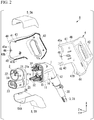
FIG. 2 is an exploded perspective view of the connector ofFIG. 1 . -
FIG. 3 is a side sectional view of the connector ofFIG. 1 . -
FIG. 4 is a side view showing an internal structure of the connector ofFIG. 1 . -
FIG. 5 is cross-sectional view showing a portion of the connector ofFIG. 1 . -
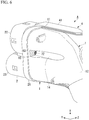
FIG. 6 is a perspective view showing a portion of the connector ofFIG. 1 . -
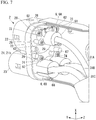
FIG. 7 is a perspective view showing the internal structure of the connector ofFIG. 1 . -
FIG. 8 is a perspective view showing a first cable fixing member of the connector ofFIG. 1 . -
FIG. 9 is a perspective view showing a second cable fixing member of the connector ofFIG. 1 . -
FIG. 10 is a view of a front housing of the connector ofFIG. 1 as viewed obliquely from the rear. -
FIG. 11 is a view of a front housing of the connector ofFIG. 1 as viewed obliquely from the front. -
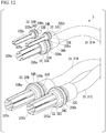
FIG. 12 is a perspective view showing a power supply cable unit of the connector ofFIG. 1 . -
FIG. 13 is a cross-sectional view showing a first power supply cable unit of the connector ofFIG. 1 and its periphery. -
FIG. 14 is a cross-sectional view showing a second power supply cable unit of the connector ofFIG. 1 and its periphery. -
FIG. 15 is a perspective view showing a portion of the connector ofFIG. 1 . - Hereinafter, an embodiment of a connector according to the present invention will be described with reference to
FIGS. 1-15 . - As shown in
FIGS. 1 to 3 , the connector A of the present embodiment is provided in a charging device such as a charging stand that supplies power to an electric vehicle (electric machine) and can be connected to the reception side connector (not shown) provided in the electric vehicle when power is supplied (during charging). The connector A is a power supply connector for supplying power to the electric machine. - In the following description, the positive direction of the Y axis in each drawing may be referred to as the front, and the negative direction of the Y axis may be referred to as the rear. In addition, the positive direction of the X axis may be referred to as the upper, and the negative direction of the X axis may be referred to as the lower. The positive direction of the X axis may be referred to as a height direction (upward). Further, the Z-axis direction may be referred to as a width direction.
- As shown in
FIGS. 1 to 3 , the connector A includes amain body case 1, afront housing 2, a power supply cable unit (cable unit) 3, anouter case 4, aprotection cover 5, and acable fixing member 6. - As shown in
FIGS. 2 and3 , themain body case 1 includes amain portion 11 and arear extension portion 12 formed so as to be continuous with themain portion 11. - The
main portion 11 is a tubular shape having a frontend opening portion 11a that opens at an end portion at a front side (front end portion) in the direction of the center axis L1 (Y-axis direction). The shape of the cross section of themain portion 11 orthogonal to the direction of the center axis L1 may be a rectangular shape, and for example, a rectangular shape in which four corners are formed in an arc shape. The front end opening 11a may be a rectangular shape, for example, a rectangular shape in which four corners are formed in an arc shape. - An annular groove 13 (see
FIG. 13 ) is formed on the outer peripheral surface of themain portion 11 at a position near the front end opening 11a. Theannular groove 13 is formed in a direction around the central axis L1. - The
rear extension portion 12 has a tubular shape extending from the rear end portion of themain portion 11 in a direction inclined in the direction of the central axis L1 (Y-axis direction). The internal space of therear extension portion 12 communicates with the internal space of themain portion 11. - As shown in
FIGS. 4 to 6 ,groove portions 14 are formed on both sides of themain body case 1 along the front-rear direction. Afastener insertion hole 20 into which thebody case fastener 72 is inserted is formed in theend plate 15 formed at the front end of thegroove 14. Thefastener insertion hole 20 is a through hole formed through theend plate portion 15. - The
main body case 1 is preferably formed integrally. Thereby, the waterproofness of themain body case 1 can be improved. - As shown in
FIGS. 2 ,10 and 11 , thefront housing 2 includes abase wall portion 21, a firstside wall portion 22, a secondside wall portion 23, aterminal tube portion 24, a holdingtube portion 25, and aperipheral wall portion 26. - The
base wall portion 21 may have a rectangular shape, for example, a rectangular plate shape in which four corners are formed in an arc shape. As shown inFIG. 2 , thebase wall portion 21 is installed so as to cover the frontend opening portion 11a of themain portion 11. - As shown in
FIGS. 10 ,13 and14 , thebase wall portion 21 includes a cable unit insertion hole 16 through which the power supply cable unit 3 is inserted, a fastener insertion hole 17 into which theexternal case fastener 71 is inserted, a fastener insertion hole 18 into which the mainbody case fastener 72 is inserted, and a fastener insertion hole 19 into which the cable fixingmember fasteners - The cable unit insertion hole 16 is formed to penetrate the
base wall portion 21 in the thickness direction. The cable unit insertion hole 16 has the first to fifth cable unit insertion holes 16A, 16B, 16C, 16D, and 16E. - As shown in
FIGS. 5 and10 , the fastener insertion hole 17 has fastener insertion holes 17A and 17B.External case fasteners - The fastener insertion holes 17A and 17B are open to the front surface 21a and are formed without penetrating the
base wall portion 21 in the thickness direction. The fastener insertion holes 17A and 17B preferably have internal-threads formed on each inner surface. - The fastener insertion hole 17A is formed at a position near one
side edge 21b of thebase wall portion 21. - The fastener insertion hole 17B is formed at a position near the
other side edge 21b of thebase wall portion 21. - As shown in
FIGS. 5 and11 , the fastener insertion hole 18 has fastener insertion holes 18A and 18B. The mainbody case fasteners - The fastener insertion holes 18A and 18B are formed in
columnar bodies rear surface 21b of thebase wall portion 21. - The fastener insertion holes 18A and 18B are open to the protrusion end surfaces 27a and 27a of the
columnar bodies base wall portion 21 in the thickness direction. That is, the depth of the fastener insertion holes 18A and 18B is such that the fastener insertion holes 18A and 18B do not reach the front surface 21a of thebase wall portion 21. The fastener insertion holes 18A and 18B preferably have internal-threads formed on each inner surface. - As shown in
FIGS. 11 and7 , the fastener insertion hole 19 includes a fastener insertion hole 19A through which the first cable fixingmember fastener 73 is inserted and a fastener insertion hole 19B through which the second cable fixingmember fastener 74 is inserted. - The fastener insertion holes 19A and 19B are respectively formed in
columnar bodies rear surface 21b of thebase wall portion 21. - The fastener insertion holes 19A and 19B are opened respectively at the protrusion end surfaces 28a and 29a of the
columnar bodies base wall portion 21 in the thickness direction. That is, a depth of each of the fastener insertion holes 19A and 19B are such that they do not reach the front surface 21a of thebase wall portion 21. The fastener insertion holes 19A and 19B preferably have internal-threads formed on the inner surface. - As shown in
FIG. 10 , the firstside wall portion 22 has substantially a tubular shape and is formed to protrude forward from the front surface 21a of thebase wall portion 21. - The first
side wall portion 22 is formed so as to collectively surround the first cable unit insertion hole 16A, the fourth cable unit insertion hole 16D, and the fifth cable unit insertion hole 16E. - The second
side wall portion 23 has an elliptical tubular shape and is formed to protrude forward from the front surface 21a of thebase wall portion 21. The secondside wall portion 23 is formed at a position lower than the firstside wall portion 22. - The second
side wall portion 23 is formed so as to collectively surround the second cable unit insertion hole 16B and the third cable unit insertion hole 16C. - The first
side wall portion 22 and the secondside wall portion 23 are formed, for example, so as to be insertable into a shell of a reception side connector (not shown). - The first
side wall portion 22 and the secondside wall portion 23 are formed integrally with thebase wall portion 21. - The
terminal tube portion 24 includes the first to fifthterminal tube portions - The first
terminal tube portion 24A has a tubular shape and is formed to protrude forward from the front surface 21a of thebase wall portion 21. The firstterminal tube portion 24A is formed so as to surround the first cable unit insertion hole 16A. The firstterminal tube portion 24A is formed in the firstside wall portion 22. - The second
terminal tube portion 24B and the third terminal tube portion 24C have a tubular shape and are formed to protrude forward from the front surface 21a of thebase wall portion 21, respectively. The secondterminal tube portion 24B is formed so as to surround the second cable unit insertion hole 16B. The third terminal tube portion 24C is formed so as to surround the third cable unit insertion hole 16C. The secondterminal tube portion 24B and the third terminal tube portion 24C are formed in the secondside wall portion 23 aligning in the Z-axis direction. - The fourth terminal tube portion 24D and the fifth terminal tube portion 24E have a tubular shape and are formed to protrude forward from the front surface 21a of the
base wall portion 21, respectively. The fourth terminal tube portion 24D is formed so as to surround the fourth cable unit insertion hole 16D. The fifth terminal tube portion 24E is formed so as to surround the fifth cable unit insertion hole 16E. The fourth terminal tube portion 24D and the fifth terminal tube portion 24E are formed in the firstside wall portion 22 aligning in the Z-axis direction. - As shown in
FIG. 11 , the holdingtube portion 25 has first to fifth holding tube portions 25A, 25B, 25C, 25D, and 25E. The first to fifth holding tube portions 25A to 25E have a tubular shape and are formed to protrude rearward from therear surface 21b of thebase wall portion 21. The first to fifth holding tube portions 25A to 25E are formed so as to surround the first to fifth cable unit insertion holes 16A to 16E, respectively. - The
peripheral wall portion 26 is formed to protrude rearward from a peripheral edge of thebase wall portion 21. - The front end portion of the
main body case 1 is inserted into theperipheral wall portion 26. - As shown in
FIG. 13 , between the inner surface of theperipheral wall portion 26 and the outer surface of themain portion 11 of the main body case 1 (specifically, the inner surface of the annular groove 13), anannular packing 51 surrounding themain portion 11 is provided. The packing 51 is an elastic material such as rubber, silicone resin, acrylate resin, or the like, and is elastically deformable. The packing 51 functions as a water blocking member that closes the gap in a liquid-tight manner by being disposed in the gap between the inner surface of theperipheral wall portion 26 and the outer surface of themain portion 11 of themain body case 1. - As shown in
FIG. 12 , the power supply cable unit 3 includes a power supply cable (cable) 31, a powersupply side terminal 32, and a packing (seal member) 33. - The power supply cable 31 includes the first to
third cables third cables 31A to 31C are inserted into themain body case 1. - As shown in
FIG. 2 , a portion of the power supply cable 31 located in therear extension portion 12 of themain body case 1 is inserted into atubular boot portion 38 that protects the power supply cable 31. - The power supply cable 31 passes through the
main portion 11 and therear extension portion 12 of themain body case 1 and extends outside theouter case 4 via therear extension portion 44 of thehousing portion 41 of theouter case 4. - As shown in
FIG. 12 , the powersupply side terminal 32 includes the first to third power supply side terminals 32A, 32B, and 32C provided at distal ends of the first tothird cables 31A to 31C, respectively, and the fourth and fifth power supply side terminals 32D and 32E electrically connected to a distal end of thefirst cable 31A. - The first to fifth power supply terminals 32A to 32E can be electrically connected to terminals of a receiving connector (not shown).
- The first to third power supply side terminals 32A to 32C respectively includes: the first to third base tube portions 32Aa, 32Ba, and 32Ca; the first to third annular convex portions 32Ab, 32Bb, and 32Cb protruding radially outward from the first to third base tube portions 32Aa, 32Ba, and 32Ca; and the first to third terminals 32Ac, 32Bc, and 32Cc protruding from the first to third base tube portions 32Aa to 32Ca toward the distal end direction of the first to
third cables 31A to 31C. - The fourth and fifth power supply side terminals 32D and 32E respectively includes: the fourth and fifth base tube portions 32Da and 32Ea; the fourth and fifth annular convex portions 32Db and 32Eb protruding radially outward from the outer peripheral surfaces of the fourth and fifth base tube portions 32Da and 32Ea; and the fourth and fifth terminals 32Dc and 32Ec protruding from the fourth and fifth base tube portions 32Da and 32Ea toward the distal end direction.
- The packing 33 includes the first to fifth
annular packings annular grooves fifth packings 33A to 33E are made of an elastic material such as rubber, silicone resin, acrylate resin, and the like and are elastically deformable. - The first to fifth power supply side terminals 32A to 32E are inserted into the first to fifth cable unit insertion holes 16A to 16E of the
front housing 2, respectively. - The first to
fifth packings 33A to 33E function as a water blocking member that close a gap in a liquid-tight manner by being arranged in the gap between the outer surfaces of the first to fifth power supply side terminals 32A to 32E (more specifically, the inner surfaces of the first to fifthannular grooves 34A to 34E) and the inner surfaces of the first to fifth holding tube portions 25A to 25E, respectively. - The power
supply side terminal 32 may be a power supply terminal that supplies power to the electric vehicle, or may be, for example, a communication terminal and the like that communicates information required for charge control between the charging device and the electric vehicle. - The number, arrangement, and the like of the components and the like constituting the power supply side terminal can be arbitrarily set, and for example, is stipulated in JEVS G105 which is a Japanese electric vehicle standard, IEC 62196-2 in Europe, and SAE J1772 in the United States, and the like.
- As shown in
FIGS. 1 to 4 , theouter case 4 includes ahousing portion 41 housing themain body case 1 and ahandle portion 42 provided at a rear portion of thehousing portion 41. - The
housing portion 41 includes amain portion 43, arear extension portion 44 formed so as to be continuous with themain portion 43, andfront plates front edge 43b of themain portion 43. - The
main portion 43 has a tubular shape. The shape of the cross section of themain portion 43 orthogonal to the direction of the central axis L1 may be a rectangular shape, for example, a rectangular shape in which four corners are formed in an arc shape. - The
main portion 43 accommodates themain portion 11 of themain body case 1. - The
rear extension portion 44 extends from the rear end portion of themain portion 43 in a direction inclined in the direction of the central axis L1 (Y-axis direction). Therear extension portion 44 accommodates therear extension portion 12 of themain body case 1. - An
annular packing 52 surrounding theboot portion 38 may be provided between the inner surface of therear extension portion 44 and the outer surface of theboot portion 38 of the power supply cable unit 3. The packing 52 is an elastic material such as rubber, silicone resin, acrylate resin, or the like and is elastically deformable. The packing 52 functions as a water blocking member that closes a gap in a liquid-tight manner by being arranged in the gap between the outer surface of theboot 38 and the inner surface of therear extension 44 of theouter case 4. - The
front plates base wall portion 21 of thefront housing 2. In thefront plates side wall portion 22 and the secondside wall portion 23 are inserted. - The fastener insertion holes 46, 46 are formed in the
front plates base wall portion 21. - As shown in
FIG. 15 , a firstliquid discharge port 47A is formed in a lower portion of themain portion 43 of thestorage portion 41. - A second
liquid discharge port 47B is formed in therear extension 44. - Since the first
liquid discharge port 47A and the secondliquid discharge port 47B are formed in theouter case 4, the liquid (for example, water) in theouter case 4 can be discharged outside through the firstliquid discharge port 47A and the secondliquid discharge port 47B. - As shown in
FIG. 2 , theouter case 4 is configured by combining a plurality of divided bodies. - For example, the
outer case 4 includes afirst case member 4A which is one of the divided members in the Z-axis direction, and asecond case member 4B which is the other divided member in the Z-axis direction. - The
protection cover 5 includes a first protection cover 5A provided on an upper portion of theouter case 4 and a second protection cover 5B provided on a lower portion of theouter case 4. - As shown in
FIG. 15 , in the second protection cover 5B, aliquid discharge port 54A formed at a position overlapping the firstliquid discharge port 47A. - Thus, the liquid discharged from the first
liquid discharge port 47A of theouter case 4 can be discharged to the outside through theliquid discharge port 54A. - As shown in
FIGS. 7 to 9 , the cable fixing member (fixing member) 6 includes a first cable fixing member 6A and a second cable fixing member 6B. - As shown in
FIGS. 7 ,8 , and12 , the first cable fixing member 6A includes amain body 61 and a plurality of fixingportions 62. - The
main body 61 includes afirst tube portion 63A capable of accommodating the first power supply side terminal 32A of thefirst cable 31A, afourth tube portion 63D capable of accommodating the fourth power supply side terminal 32D, and afifth tube portion 63E capable of accommodating the fifth power supply side terminal 32E. - The
first tube portion 63A includes a firstmovement restriction portion 64A, and the rearward movement of the first power supply side terminal 32A can be restricted by the firstmovement restriction portion 64A. Thefourth tube portion 63D has a fourthmovement restriction portion 64D, and the rearward movement of the fourth power supply side terminal 32D can be restricted by the fourthmovement restriction portion 64D. Thefifth tube portion 63E includes a fifthmovement restriction portion 64E, and the rearward movement of the fifth power supply side terminal 32E can be restricted by the fifthmovement restriction portion 64E. - The fixing
portion 62 is formed so as to protrude laterally from themain body portion 61 and includes aninsertion hole 62a through which the first cable fixingmember fastener 73 is inserted. - By fixing the fixing
portion 62 to thebase wall portion 21 by the first cable fixingmember fastener 73, the first power supply side terminal 32A, the fourth power supply side terminal 32D, and the fifth power supply side terminal 32E of thefirst cable 31A can be fixed to therear surface 21b of thebase wall portion 21. - As shown in
FIGS. 7 ,9 and12 , the second cable fixing member 6B includes amain body portion 66 and a plurality of fixingportions 67. - The
main body 66 includes asecond tube portion 63B capable of accommodating the second power supply side terminal 32B of thesecond cable 31B and athird tube portion 63C capable of accommodating the third power supply side terminal 32C of thethird cable 31C. - The
second tube portion 63B includes a secondmovement restriction portion 64B, and the rearward movement of the second power supply side terminal 32B can be restricted by the secondmovement restriction portion 64B. Thethird tube portion 63C includes a thirdmovement restriction portion 64C, and the rearward movement of the third power supply side terminal 32C can be restricted by the thirdmovement restriction portion 64C. - The fixing
portion 67 is formed so as to protrude laterally from themain body portion 66 and has aninsertion hole 67a through which the second cable fixingmember fastener 74 is inserted. - The fixing
portion 67 is fixed to thebase wall portion 21 by the second cable fixingmember fastener 74, so that the second power supply side terminal 32B of thesecond cable 31B and the third power supply side terminal 32C of thethird cable 31C can be fixed to therear surface 21b of thebase wall portion 21. - As shown in
FIG. 5 , the mainbody case fastener 72 includes ahead 72a and a shaft portion 72b extending from thehead 72a. The shaft portion 72b may be a screw shaft portion having a screw formed on the outer peripheral surface. - As shown in
FIGS. 5 and6 , the mainbody case fastener 72 is inserted into thefastener insertion hole 20 of theend plate portion 15 of themain body case 1 and fixed to the fastener insertion hole 18 by screwing or the like; thereby, theend plate portion 15 of themain body case 1 is fixed to thebase wall portion 21 of thefront housing 2. - A packing 53 surrounding the shaft portion 72b can be provided between the
head portion 72a and theend plate portion 15. - The packing 53 is made of an elastic material such as rubber, silicone resin, acrylate resin, or the like, and is elastically deformable. The packing 53 functions as a water blocking member that closes a gap in a liquid-tight manner by being arranged in the gap between the
head 72a and theend plate 15. Therefore, the mainbody case fasteners 72 are fixed to thebase wall portion 21 in a liquid-tight manner with respect to the fastener insertion holes 20. Thereby, it is possible to prevent water from entering into themain body case 1 through thefastener insertion hole 20. - As shown in
FIG. 5 , theouter case fastener 71 includes ahead portion 71a and ashaft portion 71b extending from thehead portion 71a. Theshaft portion 71b may be a screw shaft portion having a screw formed on the outer peripheral surface. - The
outer case fastener 71 is inserted into thefastener insertion hole 46 and fixed to the fastener insertion hole 17 by screwing or the like; thereby, thefront plate 45 of theouter case 4 is fixed to thebase wall portion 21 of thefront housing 2. - For example, in a connector including a structure in which a power supply cable unit is fixed to a terminal plate, in order to fix the terminal plate to the front housing and the main body case, an insertion hole for a fastener is formed in each of these members, and each member needs to be fixed to the terminal by a fastener. Therefore, since the fixing structure is complicated, it is difficult to secure high waterproof performance at the front portion of the connector including the front housing where the force is easily applied by fitting with the reception side connector.
- On the other hand, in the connector A of the present embodiment, since the power supply cable unit 3 is directly fixed to the
base wall portion 21 of thefront housing 2, the fixing structure at the front portion of the connector can be simplified as compared with the structure including the terminal plate. Therefore, waterproofness can be secured despite the fact that force is easily applied to the front housing by fitting with the reception side connector. - In addition, since the connector A includes the
outer case 4 that accommodates themain body case 1, thefastener insertion hole 20 that fixes themain body case 1 and thefront housing 2 can be surrounded by theouter case 4. Therefore, the waterproofness of the fixing structure between themain body case 1 and thefront housing 2 can be enhanced. - In addition, the mechanical strength of the connector A can be increased by the double wall structure of the
main body case 1 and theouter case 4. - In the connector A, since the fastener insertion holes 20 fixing the
main body case 1 to thefront housing 2 by the mainbody case fasteners 72 are formed in themain body case 1, the fastener insertion holes 20, which are through holes, are arranged at a position away from thefront housing 2. Therefore, it is possible to make it difficult for water to enter themain body case 1 through thefastener insertion hole 20. - The
outer case 4 is fixed to thefront housing 2 by anouter case fastener 71 which is a fastener different from the mainbody case fastener 72. Therefore, compared with the case where themain case 1, thefront housing 2, and theouter case 4 are fixed by a common fastener, the formation of through holes can be reduced and the waterproof performance can be improved. - Since the connector A includes the
cable fixing member 6 fixing the power supply cable unit 3 to therear surface 21b of thebase wall portion 21, the movement of the power supply cable unit 3 can be restricted. Therefore, inundation from the cable unit insertion hole 16 can be avoided. - As mentioned above, although the embodiment according to the connector of the present invention is described, the present invention is not limited to the above-mentioned embodiments, and various changes can be made without departing from the spirit of the present invention.
- For example, the main body case is preferably an integrally formed product, however, may have a configuration in which a plurality of divided bodies are combined.
- The connector A shown in
FIG. 1 and the like is a power supply connector supplying power to an electric machine such as an electric vehicle, however, the connector of the present embodiment may be a power reception connector receiving power from the electric machine. When the connector A is used as a power reception connector, the power supply cable unit 3, the power supply cable 31, and the powersupply side terminal 32 in the connector A function as a power reception cable unit, a power reception cable, and a power reception side terminal, respectively. - A: Connector, 1: Main body case, 1a: Front end opening portion, 2: Front housing, 3: Power supply cable unit, 4: External case, 6: Cable fixing member (fixing member), 16: Cable unit insertion hole, 20: Fastener insertion hole, 21: base wall portion, 21b: rear surface, 22: first side wall portion, 23: second side wall portion, 31: power supply cable, 32: power supply side terminal, 47A: first liquid discharge port, 47B: Second liquid discharge port, 71: external case fastener, L1: central axis
Claims (7)
- A connector connectable to a reception side connector of the electric machine, the connector comprising:a main body case formed in a tubular shape and comprising a front end opening portion that opens at a front end portion in a central axis direction of the tubular shape;a front housing comprising a base wall portion closing the front end opening portion of the main body case and a side wall portion protruding forward from the base wall portion and fitted to the reception side connector; anda cable unit comprising a cable inserted into the main body case and a terminal provided at a distal end of the cable and protruding forward of the base wall portion,wherein the base wall portion of the front housing has a cable unit insertion hole through which the cable unit is inserted, andwherein the cable unit is fixed to the base wall portion in a state where liquid tightness with respect to the unit insertion hole is secured.
- The connector according to claim 1, further comprising an outer case accommodating the main body case.
- The connector according to claim 1, wherein the main body case has a fastener insertion hole that is a through hole and is fixed to the front housing by a body case fastener inserted into the fastener insertion hole.
- The connector according to claim 2, wherein the outer case is fixed to the front housing by an outer case fastener.
- The connector according to any one of claims 1 to 4, further comprising a fixing member fixing the cable unit to a rear surface of the base wall portion.
- The connector according to any one of claims 1 to 5, wherein the main body case is formed integrally.
- The connector according to claim 2 or 4, wherein a liquid discharge port discharging a liquid in the outer case is formed in the outer case.
Applications Claiming Priority (2)
| Application Number | Priority Date | Filing Date | Title |
|---|---|---|---|
| JP2017234572A JP2019102363A (en) | 2017-12-06 | 2017-12-06 | connector |
| PCT/JP2018/033732 WO2019111478A1 (en) | 2017-12-06 | 2018-09-12 | Connector |
Publications (1)
| Publication Number | Publication Date |
|---|---|
| EP3723211A1 true EP3723211A1 (en) | 2020-10-14 |
Family
ID=66751573
Family Applications (1)
| Application Number | Title | Priority Date | Filing Date |
|---|---|---|---|
| EP18885254.5A Withdrawn EP3723211A1 (en) | 2017-12-06 | 2018-09-12 | Connector |
Country Status (3)
| Country | Link |
|---|---|
| EP (1) | EP3723211A1 (en) |
| JP (1) | JP2019102363A (en) |
| WO (1) | WO2019111478A1 (en) |
Cited By (1)
| Publication number | Priority date | Publication date | Assignee | Title |
|---|---|---|---|---|
| EP4625719A1 (en) * | 2024-03-26 | 2025-10-01 | HARTING Automotive GmbH | Water resistant charging connector |
Families Citing this family (1)
| Publication number | Priority date | Publication date | Assignee | Title |
|---|---|---|---|---|
| US12220997B2 (en) * | 2021-07-15 | 2025-02-11 | Japan Aviation Electronics Industry, Limited | Charging connector |
Family Cites Families (8)
| Publication number | Priority date | Publication date | Assignee | Title |
|---|---|---|---|---|
| JP4898855B2 (en) * | 2009-02-04 | 2012-03-21 | 矢崎総業株式会社 | connector |
| DE102010017458B4 (en) | 2010-06-18 | 2012-02-16 | Phoenix Contact Gmbh & Co. Kg | electric plug |
| JP5197699B2 (en) * | 2010-09-09 | 2013-05-15 | 住友電装株式会社 | Charging connector |
| JP5763427B2 (en) * | 2011-06-07 | 2015-08-12 | 矢崎総業株式会社 | connector |
| WO2012175573A1 (en) * | 2011-06-20 | 2012-12-27 | Fci Automotive Holding | Electrical multicontact plug and assembly method for charging system |
| JP6182324B2 (en) | 2013-02-20 | 2017-08-16 | 日本航空電子工業株式会社 | Electric vehicle power connector |
| JP6169385B2 (en) * | 2013-03-27 | 2017-07-26 | 矢崎総業株式会社 | Charging connector |
| JP5690914B1 (en) * | 2013-12-16 | 2015-03-25 | 株式会社フジクラ | Power supply connector |
-
2017
- 2017-12-06 JP JP2017234572A patent/JP2019102363A/en not_active Withdrawn
-
2018
- 2018-09-12 EP EP18885254.5A patent/EP3723211A1/en not_active Withdrawn
- 2018-09-12 WO PCT/JP2018/033732 patent/WO2019111478A1/en not_active Ceased
Cited By (2)
| Publication number | Priority date | Publication date | Assignee | Title |
|---|---|---|---|---|
| EP4625719A1 (en) * | 2024-03-26 | 2025-10-01 | HARTING Automotive GmbH | Water resistant charging connector |
| DE102024108577A1 (en) * | 2024-03-26 | 2025-10-02 | HARTING Automotive GmbH | Water-resistant charging connector |
Also Published As
| Publication number | Publication date |
|---|---|
| WO2019111478A1 (en) | 2019-06-13 |
| JP2019102363A (en) | 2019-06-24 |
Similar Documents
| Publication | Publication Date | Title |
|---|---|---|
| CN108352474B (en) | Battery pack, electrical device, and charging device | |
| US20110300424A1 (en) | Battery pack | |
| US9634503B2 (en) | Battery chargers | |
| EP3723211A1 (en) | Connector | |
| US20160013673A1 (en) | Portable energy storage and power supply system | |
| CN102097607A (en) | Battery pack and motor-driven tool using the same | |
| CN110832710B (en) | socket for charging | |
| JP2019186022A (en) | Waterproof cover and charge connector with the same | |
| US5561273A (en) | Electrical cable holding case | |
| US20140287801A1 (en) | Protective shell and charging device assembly for mobile phone | |
| US20210057834A1 (en) | Connector | |
| CN110277756B (en) | Wire retention structure | |
| JP7019971B2 (en) | Combination | |
| JP5667314B1 (en) | connector | |
| US20240204451A1 (en) | Connector | |
| US9327660B2 (en) | Wiring harness | |
| CN110350360A (en) | Connector with cover | |
| US12586964B2 (en) | Grommet and inlet assembly | |
| WO2023008027A1 (en) | Charging connector | |
| KR102461288B1 (en) | Fuse box integrated connector block | |
| KR102417167B1 (en) | Charging inlet | |
| EP1804340B1 (en) | Fixation structure for rear cover | |
| CN114976738B (en) | Connectors | |
| US20240162649A1 (en) | Grommet and inlet assembly | |
| CN119948708A (en) | Waterproof structure of connector and battery pack having connector |
Legal Events
| Date | Code | Title | Description |
|---|---|---|---|
| STAA | Information on the status of an ep patent application or granted ep patent |
Free format text: STATUS: THE INTERNATIONAL PUBLICATION HAS BEEN MADE |
|
| PUAI | Public reference made under article 153(3) epc to a published international application that has entered the european phase |
Free format text: ORIGINAL CODE: 0009012 |
|
| STAA | Information on the status of an ep patent application or granted ep patent |
Free format text: STATUS: REQUEST FOR EXAMINATION WAS MADE |
|
| 17P | Request for examination filed |
Effective date: 20200529 |
|
| AK | Designated contracting states |
Kind code of ref document: A1 Designated state(s): AL AT BE BG CH CY CZ DE DK EE ES FI FR GB GR HR HU IE IS IT LI LT LU LV MC MK MT NL NO PL PT RO RS SE SI SK SM TR |
|
| AX | Request for extension of the european patent |
Extension state: BA ME |
|
| STAA | Information on the status of an ep patent application or granted ep patent |
Free format text: STATUS: THE APPLICATION HAS BEEN WITHDRAWN |
|
| 18W | Application withdrawn |
Effective date: 20201201 |