EP3723201B1 - Multi-frequency antenna transmission device - Google Patents
Multi-frequency antenna transmission device Download PDFInfo
- Publication number
- EP3723201B1 EP3723201B1 EP18852766.7A EP18852766A EP3723201B1 EP 3723201 B1 EP3723201 B1 EP 3723201B1 EP 18852766 A EP18852766 A EP 18852766A EP 3723201 B1 EP3723201 B1 EP 3723201B1
- Authority
- EP
- European Patent Office
- Prior art keywords
- driven gear
- lead screw
- gear
- transmission device
- antenna transmission
- Prior art date
- Legal status (The legal status is an assumption and is not a legal conclusion. Google has not performed a legal analysis and makes no representation as to the accuracy of the status listed.)
- Active
Links
Images


Classifications
-
- F—MECHANICAL ENGINEERING; LIGHTING; HEATING; WEAPONS; BLASTING
- F16—ENGINEERING ELEMENTS AND UNITS; GENERAL MEASURES FOR PRODUCING AND MAINTAINING EFFECTIVE FUNCTIONING OF MACHINES OR INSTALLATIONS; THERMAL INSULATION IN GENERAL
- F16H—GEARING
- F16H37/00—Combinations of mechanical gearings, not provided for in groups F16H1/00 - F16H35/00
- F16H37/12—Gearings comprising primarily toothed or friction gearing, links or levers, and cams, or members of at least two of these types
-
- F—MECHANICAL ENGINEERING; LIGHTING; HEATING; WEAPONS; BLASTING
- F16—ENGINEERING ELEMENTS AND UNITS; GENERAL MEASURES FOR PRODUCING AND MAINTAINING EFFECTIVE FUNCTIONING OF MACHINES OR INSTALLATIONS; THERMAL INSULATION IN GENERAL
- F16H—GEARING
- F16H25/00—Gearings comprising primarily only cams, cam-followers and screw-and-nut mechanisms
- F16H25/18—Gearings comprising primarily only cams, cam-followers and screw-and-nut mechanisms for conveying or interconverting oscillating or reciprocating motions
- F16H25/20—Screw mechanisms
- F16H25/24—Elements essential to such mechanisms, e.g. screws, nuts
-
- H—ELECTRICITY
- H01—ELECTRIC ELEMENTS
- H01Q—ANTENNAS, i.e. RADIO AERIALS
- H01Q1/00—Details of, or arrangements associated with, antennas
- H01Q1/12—Supports; Mounting means
- H01Q1/125—Means for positioning
-
- F—MECHANICAL ENGINEERING; LIGHTING; HEATING; WEAPONS; BLASTING
- F16—ENGINEERING ELEMENTS AND UNITS; GENERAL MEASURES FOR PRODUCING AND MAINTAINING EFFECTIVE FUNCTIONING OF MACHINES OR INSTALLATIONS; THERMAL INSULATION IN GENERAL
- F16H—GEARING
- F16H25/00—Gearings comprising primarily only cams, cam-followers and screw-and-nut mechanisms
- F16H25/18—Gearings comprising primarily only cams, cam-followers and screw-and-nut mechanisms for conveying or interconverting oscillating or reciprocating motions
- F16H25/20—Screw mechanisms
- F16H2025/2062—Arrangements for driving the actuator
- F16H2025/2071—Disconnecting drive source from the actuator, e.g. using clutches for release of drive connection during manual control
-
- F—MECHANICAL ENGINEERING; LIGHTING; HEATING; WEAPONS; BLASTING
- F16—ENGINEERING ELEMENTS AND UNITS; GENERAL MEASURES FOR PRODUCING AND MAINTAINING EFFECTIVE FUNCTIONING OF MACHINES OR INSTALLATIONS; THERMAL INSULATION IN GENERAL
- F16H—GEARING
- F16H25/00—Gearings comprising primarily only cams, cam-followers and screw-and-nut mechanisms
- F16H25/18—Gearings comprising primarily only cams, cam-followers and screw-and-nut mechanisms for conveying or interconverting oscillating or reciprocating motions
- F16H25/20—Screw mechanisms
- F16H2025/2062—Arrangements for driving the actuator
- F16H2025/2081—Parallel arrangement of drive motor to screw axis
-
- F—MECHANICAL ENGINEERING; LIGHTING; HEATING; WEAPONS; BLASTING
- F16—ENGINEERING ELEMENTS AND UNITS; GENERAL MEASURES FOR PRODUCING AND MAINTAINING EFFECTIVE FUNCTIONING OF MACHINES OR INSTALLATIONS; THERMAL INSULATION IN GENERAL
- F16H—GEARING
- F16H3/00—Toothed gearings for conveying rotary motion with variable gear ratio or for reversing rotary motion
- F16H3/02—Toothed gearings for conveying rotary motion with variable gear ratio or for reversing rotary motion without gears having orbital motion
- F16H3/20—Toothed gearings for conveying rotary motion with variable gear ratio or for reversing rotary motion without gears having orbital motion exclusively or essentially using gears that can be moved out of gear
- F16H3/22—Toothed gearings for conveying rotary motion with variable gear ratio or for reversing rotary motion without gears having orbital motion exclusively or essentially using gears that can be moved out of gear with gears shiftable only axially
-
- H—ELECTRICITY
- H01—ELECTRIC ELEMENTS
- H01Q—ANTENNAS, i.e. RADIO AERIALS
- H01Q21/00—Antenna arrays or systems
- H01Q21/30—Combinations of separate antenna units operating in different wavebands and connected to a common feeder system
-
- H—ELECTRICITY
- H01—ELECTRIC ELEMENTS
- H01Q—ANTENNAS, i.e. RADIO AERIALS
- H01Q3/00—Arrangements for changing or varying the orientation or the shape of the directional pattern of the waves radiated from an antenna or antenna system
- H01Q3/02—Arrangements for changing or varying the orientation or the shape of the directional pattern of the waves radiated from an antenna or antenna system using mechanical movement of antenna or antenna system as a whole
Definitions
- the invention as claimed relates to the technical field of transmission devices for mobile communication antennas, and more particularly to a multiband antenna transmission device.
- a large-capacity multiband antenna of an existing product in which a plurality of frequency bands are collectively assembled in a single antenna, a regulator for the respective frequency band is connected with a rack, and a plurality of racks are arranged side by side on a plane and driven by a common driving gear to move, thereby realizing the regulation. Regulation of the different racks is achieved when the common gear meshes with different racks at different positions. Since the common gear has to be moved to different racks positions, strict requirements are imposed on the positions of the common gear and the racks, and the common gear of the existing product is prone to be jammed when moving, which affects the timeliness and accuracy of the regulation of the antenna.
- CN 107 394 403 A , KR 101 600 832 B1 , and CN 205 335 430 U each involves a multiband antenna transmission device falling within the wording of the pre-characterizing portion of claim 1.
- a multiband antenna transmission device including:
- the boss of shifter pushes one of the driven gears such that the driven gear is connected with the corresponding lead screw, and whereby the driven gear is in mesh with the driving gear for transmission, thereby driving the lead screw to rotate, and in such condition, the first elastic member is in a compressed state, in which the first elastic member can reliably transmit the power of the driven gear to the lead screw.
- the boss of shifter does not push the above-mentioned driven gear, and the first elastic member is elongated, such that the driven gear is reset and separated from the driving gear, and the power transmission is cut off.
- the multiband antenna transmission adopts a circumferential layout, which saves a lot of space and minimizes the overall volume.
- the screw assembly to be regulated is determined by the shifter to achieve one driving power completing the regulation of a plurality of screw assemblies, that is, one drags multiple, and the other power source is the regulation power configured to regulate the shifter.
- the connected driven gear and lead screw and the compressed first elastic member are jointly driven and rotated, so that the regulation action is smoother and the jamming phenomenon is avoided.
- orientation or positional relationship indicated by terms “length”, “width”, “upper”, “lower”, “front”, “back”, “left”, “right”, “vertical”, “horizontal”, “top”, bottom”, “inside”, “outside”, or the like is based on the orientation or positional relationship shown in the drawings, and is merely for facilitating and simplifying the description of the invention as claimed, and does not indicate or imply that the device or component referred to must have a particular orientation or be constructed and operated in a particular orientation, and thus are not to be construed as defining the invention as claimed.
- first and second are adopted for descriptive purposes only and are not to be construed as indicating or implying a relative importance or implicitly indicating the number of technical features indicated.
- features defining “first” and “second” may include one or more of the features either explicitly or implicitly.
- the meaning of "a plurality of” or “multiple” is two or more unless otherwise particularly defined.
- the multiband antenna transmission device includes: a driving gear 10, a shifter 20, and a plurality of screw assemblies 30.
- the shifter 20 and the driving gear 10 are coaxially and rotatably arranged, and the shifter 20 includes a plate 21 and a boss 22 protruding from a side of the plate 21.
- the plurality of screw assemblies 30 are arranged in a circumferential direction of the driving gear 10.
- Each of the plurality of screw assemblies 30 includes: a lead screw 31, a driven gear 32 selectively connected with or separated from the lead screw 31, and a first elastic member 33 arranged between the lead screw 31 and the driven gear 32.
- the multiband antenna transmission device is configured such that the boss 22 sequentially pushes the driven gear 32 of one of the plurality of screw assemblies, during rotation of the shifter 20, into connection with the corresponding lead screw 31 and into mesh with the driving gear 10 for transmission.
- the boss 22 of shifter 20 pushes one of the driven gears 32 such that the driven gear 32 is connected with the corresponding lead screw 31, and the driven gear 32 meshes with the driving gear 10 for transmission, thereby driving the lead screw 31 to rotate, and in such condition, the first elastic member 33 is in a compressed state, in which the first elastic member 33 can reliably transmit the power of the driven gear 32 to the lead screw 31.
- the boss 22 of shifter 20 does not push the above-mentioned driven gear 32, and the first elastic member 33 is elongated, such that the driven gear 32 is reset and separated from the driving gear 10, and the power transmission is cut off.
- the multiband antenna transmission adopts a circumferential layout, which saves a lot of space and minimizes the overall volume.
- the screw assembly 30 to be regulated is determined by the shifter 20 to achieve one driving power completing the regulation of a plurality of screw assemblies 30, that is, one drags multiple, and the other power source is the regulation power configured to regulate the shifter 20.
- the connected driven gear 32 and lead screw 31 and the compressed first elastic member 33 are jointly driven and rotated, so that the regulation action is smoother and the jamming phenomenon is avoided.
- the driving gear 10 is rotatable about its own axis, but is unable to move forward or backward.
- the shifter 20 is sleeved outside the driving gear 10 and coaxial with the driving gear 10, the shifter 20 is able to rotate about its own axis, but does not rotate along with the rotation of the driving gear 10, and the shifter 20 cannot move forward or backward.
- a smooth guiding surface 221 is provided between each end of the boss 22 and the plate 21, thereby guiding an end face of the respective lead screw assembly 30 to move to a highest position of the boss 22.
- the plurality of screw assemblies 30 are uniformly and circumferentially distributed around an axis of the driving gear 10. Under the action of the first elastic member 33, the end face of the corresponding screw assembly 30 is in contact with the shifter 20, and is able to be in contact with the plate 21 or the boss 22. A distance between the axis of boss 22 and an axis of the shifter 20 is equal to a distance between an axis of respective screw assembly 30 and the axis of shifter 20.
- the shifter 20 is rotated to rotate the boss 22 to different positions and is capable of pushing the respective driven gears 32 in the axial direction of the driven gear 32.
- the front and rear positions of the driven gear 32 are not fixed, the driven gears 32 are slidably mounted on a frame, and are also rotatable about their own axes.
- One end of the first elastic member 33 is in contact with the driven gear 32, and the other end is in contact with the end face of the lead screw 31.
- the lead screw 31 and the driven gear 32 are on the same axis, and the lead screw 31 is unable to move forward or backward but is able to rotate about its own axis.
- the lead screw 31 and the driven gear 32 are coaxially arranged, and the end of the lead screw 31 and the driven gear 32 are selectively connected with or separated from each other in the axial direction.
- the first elastic member 33 is compressed in such condition, the rotation of the driven gear 32 is transmitted to the lead screw 31 through the first elastic member 33.
- the first elastic member 33 ensures timely transmission of rotation when the lead screw 31 and the driven gear 32 are not reliably connected.
- the driving gear 10, the shifter 20, and the screw assembly 30 are all mounted on the frame (not shown in figures).
- the respective screw assembly 30 further includes a second elastic member 34 arranged for the corresponding driven gear 32, and a distal end of the second elastic member 34 from the driven gear 32 faces the shifter 20, and when the shifter 20 rotates, the boss 22 sequentially abuts against the distal end of the second elastic member 34 of the respective screw assembly 30 to push the corresponding driven gear 32, thereby enabling the corresponding driven gear 32 to be connected with the lead screw 31 and to mesh with the driving gear 10 for transmission.
- One end of the second elastic member 34 is in contact with the end face of the driven gear 32, and the other end is in contact with the shifter 20, and the second elastic member 34 is compressible along its axis.
- the boss 22 is rotated to different positions by rotating the shifter 20 and is therefore capable of contacting with different second elastic members 34.
- the second elastic member 34 is configured to enable the boss 22 to reliably push one of the driven gears 32 to move via the corresponding second elastic member 34.
- the distal end of the second elastic member 34 from the corresponding driven gear 32 is connected with an abutting block 35.
- the abutting block 35 can reliably abut against the plate 21 or the boss 22 of the shifter 20, which makes the operation reliable.
- the lead screw 31 and the driven gear 32 are selectively connected with or separated from each other by a coupler.
- the end of the lead screw 31 close to the driven gear 32 is connected with the driven gear 32 via the coupler which can be in various forms, and the coupler is capable of transmitting the rotation of the driven gear 32 to the lead screw 31.
- the first elastic member 33 ensures timely transmission of the rotation when the coupler is not reliably connected.
- the coupler and the compressed first elastic member 33 are jointly driven and rotated to make the regulation action smoother and avoid the jamming phenomenon.
- one side of the driven gear 32 is provided with a shaped hole 321, and one end of the lead screw 31 is provided with an insertion shaft 311 configured to be inserted and fitted into the shaped hole 321.
- the shaped hole 321 may be a regular polygonal hole or a D-shaped hole or other type of holes, and accordingly, the insertion shaft 311 is an insertion shaft with fitted shape.
- one side of the driven gear 32 is provided with a spline slot, and one end of the lead screw 31 is provided with a spline shaft configured to be inserted and fitted into the spline slot. Specific embodiment can be selected as needed.
- the connection state is achieved when the shaft is inserted into the hole or the groove, and the separation state is achieved when the shaft is separated from the hole or the groove.
- two ends of the first elastic member 33 abut against one end of the lead screw 31 and a side face of the driven gear 32 respectively.
- the structure is easy to be processed and assembled, and the first elastic member 33 is reliably disposed between the lead screw 31 and the driven gear 32.
- the lead screw 31 and the driven gear 32 are selectively connected with or separated from each other. When the first elastic member 33 is compressed, the rotation of the driven gear 32 can be transmitted to the lead screw 31 through the first elastic member 33, thereby avoiding the untimely connection between the lead screw 31 and the driven gear 32.
- a side of the driven gear 32 facing toward the lead screw 31 extends to form a limit segment 322, and the first elastic member 33 is sleeved outside the limit segment 322.
- the structure facilitates the assembly of the first elastic member 33.
- the driving gear 10 includes a gear portion 11 and a connection shaft 12 connected with the gear portion 11, the plate 21 defines therein a through hole 211, and the connection shaft 12 passes through the through hole 211.
- the driving gear 10 includes a gear portion 11 and a connection shaft 12 connected with the gear portion 11, the plate 21 defines therein a through hole 211, and the connection shaft 12 passes through the through hole 211.
- the shifter 20 further includes an external gear 23 connected with a side of the plate 21 away from the boss 22, and the connection shaft 12 sequentially passes through the through hole 211 and an inner hole of and the external gear 23, and the external gear 23 meshes with an input gear 40.
- the rotation of the input gear 40 drives the external gear 23 to rotate, so that the boss 22 of the shifter 20 rotates, and the rotation of the shifter 20 does not drive the driving gear 10 to rotate.
- the input gear 40 is rotatable about itself, and it cannot be moved forward or backward.
- the input gear 40 is mounted to the frame.
- the axis of the driving gear 10 and the axis of the lead screw 31 of the respective screw assembly 30 are parallel to each other.
- the solution results in easy assemblage and a compact structure.
- the circumferential layout saves a lot of space and minimizes the overall volume.
Landscapes
- Engineering & Computer Science (AREA)
- General Engineering & Computer Science (AREA)
- Mechanical Engineering (AREA)
- Transmission Devices (AREA)
- Details Of Aerials (AREA)
Description
- The invention as claimed relates to the technical field of transmission devices for mobile communication antennas, and more particularly to a multiband antenna transmission device.
- With the development of mobile communication technology, large-capacity multi-band antennas have become an important development trend of mobile communication antennas. To accommodate more antennas within a limited space, it is not possible to simply assemble multiband antennas together, which would otherwise make the whole antenna bulky, heavy, and inefficient.
- A large-capacity multiband antenna of an existing product, in which a plurality of frequency bands are collectively assembled in a single antenna, a regulator for the respective frequency band is connected with a rack, and a plurality of racks are arranged side by side on a plane and driven by a common driving gear to move, thereby realizing the regulation. Regulation of the different racks is achieved when the common gear meshes with different racks at different positions. Since the common gear has to be moved to different racks positions, strict requirements are imposed on the positions of the common gear and the racks, and the common gear of the existing product is prone to be jammed when moving, which affects the timeliness and accuracy of the regulation of the antenna.
CN 107 394 403 A ,KR 101 600 832 B1 CN 205 335 430 U each involves a multiband antenna transmission device falling within the wording of the pre-characterizing portion of claim 1. - It is an object of the invention as claimed to provide a multiband antenna transmission device, so as to solve the technical problem that the existing multiband antenna adopts the gear and racks to regulate positions, which imposes strict requirements on the positions of the gear and the racks and would result in jamming of the common gear during the moving thereof.
- In order to achieve the above object, the technical solution adopted by the invention as claimed is to provide a multiband antenna transmission device, including:
- a driving gear;
- a shifter, where the shifter and the driving gear are coaxially and rotatably arranged, and the shifter comprises a plate and a boss protruding from a side of the plate; and
- a plurality of screw assemblies, arranged in a circumferential direction of the driving gear, with each of the plurality of screw assemblies including: a lead screw, a driven gear, and a first elastic member arranged between the lead screw and the driven gear; characterized in that
- the driven gear is selectively connected with or separated from the lead screw; and the multiband antenna transmission device is configured such that the boss sequentially pushes the driven gear of one of the plurality of the screw assemblies, during rotation of the shifter, into connection with the corresponding lead screw and into mesh with the driving gear for transmission.
- By rotating the shifter, the boss of shifter pushes one of the driven gears such that the driven gear is connected with the corresponding lead screw, and whereby the driven gear is in mesh with the driving gear for transmission, thereby driving the lead screw to rotate, and in such condition, the first elastic member is in a compressed state, in which the first elastic member can reliably transmit the power of the driven gear to the lead screw. By rotating the shifter, the boss of shifter does not push the above-mentioned driven gear, and the first elastic member is elongated, such that the driven gear is reset and separated from the driving gear, and the power transmission is cut off. The multiband antenna transmission adopts a circumferential layout, which saves a lot of space and minimizes the overall volume. The screw assembly to be regulated is determined by the shifter to achieve one driving power completing the regulation of a plurality of screw assemblies, that is, one drags multiple, and the other power source is the regulation power configured to regulate the shifter. The connected driven gear and lead screw and the compressed first elastic member are jointly driven and rotated, so that the regulation action is smoother and the jamming phenomenon is avoided.
- In order to illustrate the technical solutions in the embodiments of the invention as claimed more clearly, the drawings used in the embodiments or the description of the prior art will be briefly described below, it is obvious that the drawings in the following description are only some embodiments of the invention as claimed, other drawings may be obtained by ordinary persons skilled in the art without any creative work.
-
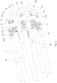
FIG. 1 is a front view of the multiband antenna transmission device provided by some embodiments of the invention as claimed; -
FIG. 2 is a perspective assembled view of the multiband antenna transmission device ofFIG. 1 ; and -
FIG. 3 is an exploded perspective view of the multiband antenna transmission device ofFIG. 2 . - In order to make the technical problems to be solved, technical solutions, and beneficial effects of the invention as claimed more clear, the invention as claimed will be further described in detail hereinbelow with reference to the accompanying drawings and embodiments. It should be understood that the specific embodiments described herein are merely intended to explain the application rather than to limit the invention as claimed.
- It should be noted that when an element is referred to as being "fixed" or "arranged" at/in/on another element, it can be directly at/in/on the other element. When an element is referred to as being "connected" to/with the another element, it can be directly or indirectly connected to/with the other element.
- It should be understood that the orientation or positional relationship indicated by terms "length", "width", "upper", "lower", "front", "back", "left", "right", "vertical", "horizontal", "top", bottom", "inside", "outside", or the like is based on the orientation or positional relationship shown in the drawings, and is merely for facilitating and simplifying the description of the invention as claimed, and does not indicate or imply that the device or component referred to must have a particular orientation or be constructed and operated in a particular orientation, and thus are not to be construed as defining the invention as claimed.
- Moreover, the terms "first" and "second" are adopted for descriptive purposes only and are not to be construed as indicating or implying a relative importance or implicitly indicating the number of technical features indicated. Thus, features defining "first" and "second" may include one or more of the features either explicitly or implicitly. In the description of the invention as claimed, the meaning of "a plurality of" or "multiple" is two or more unless otherwise particularly defined.
- Referring to
FIGS. 1-3 , the multiband antenna transmission device provided by the invention as claimed is described herein. The multiband antenna transmission device includes: adriving gear 10, ashifter 20, and a plurality ofscrew assemblies 30. Theshifter 20 and thedriving gear 10 are coaxially and rotatably arranged, and theshifter 20 includes aplate 21 and aboss 22 protruding from a side of theplate 21. The plurality ofscrew assemblies 30 are arranged in a circumferential direction of thedriving gear 10. Each of the plurality ofscrew assemblies 30 includes: alead screw 31, a drivengear 32 selectively connected with or separated from thelead screw 31, and a firstelastic member 33 arranged between thelead screw 31 and the drivengear 32. The multiband antenna transmission device is configured such that theboss 22 sequentially pushes the drivengear 32 of one of the plurality of screw assemblies, during rotation of theshifter 20, into connection with thecorresponding lead screw 31 and into mesh with thedriving gear 10 for transmission. - By rotating the
shifter 20, theboss 22 ofshifter 20 pushes one of the drivengears 32 such that the drivengear 32 is connected with thecorresponding lead screw 31, and the drivengear 32 meshes with thedriving gear 10 for transmission, thereby driving thelead screw 31 to rotate, and in such condition, the firstelastic member 33 is in a compressed state, in which the firstelastic member 33 can reliably transmit the power of the drivengear 32 to thelead screw 31. By rotating theshifter 20, theboss 22 ofshifter 20 does not push the above-mentioned drivengear 32, and the firstelastic member 33 is elongated, such that the drivengear 32 is reset and separated from thedriving gear 10, and the power transmission is cut off. The multiband antenna transmission adopts a circumferential layout, which saves a lot of space and minimizes the overall volume. Thescrew assembly 30 to be regulated is determined by theshifter 20 to achieve one driving power completing the regulation of a plurality ofscrew assemblies 30, that is, one drags multiple, and the other power source is the regulation power configured to regulate theshifter 20. The connected drivengear 32 andlead screw 31 and the compressed firstelastic member 33 are jointly driven and rotated, so that the regulation action is smoother and the jamming phenomenon is avoided. - The
driving gear 10 is rotatable about its own axis, but is unable to move forward or backward. - The
shifter 20 is sleeved outside thedriving gear 10 and coaxial with thedriving gear 10, theshifter 20 is able to rotate about its own axis, but does not rotate along with the rotation of thedriving gear 10, and theshifter 20 cannot move forward or backward. A smooth guidingsurface 221 is provided between each end of theboss 22 and theplate 21, thereby guiding an end face of the respectivelead screw assembly 30 to move to a highest position of theboss 22. - The plurality of
screw assemblies 30 are uniformly and circumferentially distributed around an axis of thedriving gear 10. Under the action of the firstelastic member 33, the end face of thecorresponding screw assembly 30 is in contact with theshifter 20, and is able to be in contact with theplate 21 or theboss 22. A distance between the axis ofboss 22 and an axis of theshifter 20 is equal to a distance between an axis ofrespective screw assembly 30 and the axis ofshifter 20. Theshifter 20 is rotated to rotate theboss 22 to different positions and is capable of pushing the respective drivengears 32 in the axial direction of the drivengear 32. - The front and rear positions of the driven
gear 32 are not fixed, the drivengears 32 are slidably mounted on a frame, and are also rotatable about their own axes. One end of the firstelastic member 33 is in contact with the drivengear 32, and the other end is in contact with the end face of thelead screw 31. Thelead screw 31 and the drivengear 32 are on the same axis, and thelead screw 31 is unable to move forward or backward but is able to rotate about its own axis. - In a normal state, the end face of the
respective screw assembly 30 is in contact with theplate 21, and the tooth face of the drivengear 32 is not in contact with the tooth face of thedriving gear 10, in such condition, the rotation of thedriving gear 10 does not affect the position of the drivengear 32 or the position of thelead screw 31. In such condition, the firstelastic member 33 is not significantly compressed either, and the drivengear 32 and thecorresponding lead screw 31 are also separated from each other. - When regulation is required, by rotating the
shifter 20, theboss 22 on theshifter 20 is rotated to a back of acertain screw assembly 30, and theboss 22 pushes the corresponding drivengear 32 to move to a position where the corresponding drivengear 32 contacts with the tooth face of thedrive gear 10, and the drivengear 32 and an end of thelead screw 31 are in a connected state. In such condition, the rotation of thedriving gear 10 will drive the drivengear 32 to rotate, the power of thedriving gear 10 is transmitted to thelead screw 31 by the connection between the drivengear 32 and thelead screw 31 and by the firstelastic member 33, the rotation oflead screw 31 drives the corresponding regulator to work. - The
lead screw 31 and the drivengear 32 are coaxially arranged, and the end of thelead screw 31 and the drivengear 32 are selectively connected with or separated from each other in the axial direction. In case that thelead screw 31 and the drivengear 32 are not timely connected, since the firstelastic member 33 is compressed in such condition, the rotation of the drivengear 32 is transmitted to thelead screw 31 through the firstelastic member 33. The firstelastic member 33 ensures timely transmission of rotation when thelead screw 31 and the drivengear 32 are not reliably connected. - The
driving gear 10, theshifter 20, and thescrew assembly 30 are all mounted on the frame (not shown in figures). - Further, as a specific embodiment of the multiband antenna transmission device provided by the invention as claimed, the
respective screw assembly 30 further includes a secondelastic member 34 arranged for the corresponding drivengear 32, and a distal end of the secondelastic member 34 from the drivengear 32 faces theshifter 20, and when theshifter 20 rotates, theboss 22 sequentially abuts against the distal end of the secondelastic member 34 of therespective screw assembly 30 to push the corresponding drivengear 32, thereby enabling the corresponding drivengear 32 to be connected with thelead screw 31 and to mesh with thedriving gear 10 for transmission. One end of the secondelastic member 34 is in contact with the end face of the drivengear 32, and the other end is in contact with theshifter 20, and the secondelastic member 34 is compressible along its axis. Theboss 22 is rotated to different positions by rotating theshifter 20 and is therefore capable of contacting with different secondelastic members 34. The secondelastic member 34 is configured to enable theboss 22 to reliably push one of the driven gears 32 to move via the corresponding secondelastic member 34. - In the normal state, the end face of the
respective screw assembly 30 is in contact with theplate 21, the secondelastic member 34 is not significantly compressed, and the tooth face of the drivengear 32 is not in contact with the tooth face of thedriving gear 10, in such condition, the rotation of thedriving gear 10 does not affect the position of the drivengear 32 or the position of thelead screw 31. In such condition, the firstelastic member 33 is not significantly compressed either, and the drivengear 32 and thecorresponding lead screw 31 are also separated from each other. - When regulation is required, by rotating the
shifter 20, theboss 22 on theshifter 20 is rotated to a back of acertain screw assembly 30, theboss 22 pushes the corresponding secondelastic member 34, which makes the secondelastic member 34 compressed and further push the corresponding drivengear 32 to move to a position where the corresponding drivengear 32 contacts with the tooth face of thedrive gear 10, and the drivengear 32 and an end of thelead screw 31 are in a connected state. In such condition, the rotation of thedriving gear 10 will drive the drivengear 32 to rotate, the power of thedriving gear 10 is transmitted to thelead screw 31 by the connection between the drivengear 32 and thelead screw 31 and by the firstelastic member 33, the rotation oflead screw 31 drives the corresponding regulator to work. - Further, as a specific embodiment of the multiband antenna transmission device provided by the invention as claimed, the distal end of the second
elastic member 34 from the corresponding drivengear 32 is connected with an abuttingblock 35. The abuttingblock 35 can reliably abut against theplate 21 or theboss 22 of theshifter 20, which makes the operation reliable. - Further, as a specific embodiment of the multiband antenna transmission device provided by the invention as claimed, the
lead screw 31 and the drivengear 32 are selectively connected with or separated from each other by a coupler. The end of thelead screw 31 close to the drivengear 32 is connected with the drivengear 32 via the coupler which can be in various forms, and the coupler is capable of transmitting the rotation of the drivengear 32 to thelead screw 31. The firstelastic member 33 ensures timely transmission of the rotation when the coupler is not reliably connected. The coupler and the compressed firstelastic member 33 are jointly driven and rotated to make the regulation action smoother and avoid the jamming phenomenon. - Further, as a specific embodiment of the multiband antenna transmission device provided by the invention as claimed, one side of the driven
gear 32 is provided with ashaped hole 321, and one end of thelead screw 31 is provided with aninsertion shaft 311 configured to be inserted and fitted into the shapedhole 321. The shapedhole 321 may be a regular polygonal hole or a D-shaped hole or other type of holes, and accordingly, theinsertion shaft 311 is an insertion shaft with fitted shape. Or alternatively, one side of the drivengear 32 is provided with a spline slot, and one end of thelead screw 31 is provided with a spline shaft configured to be inserted and fitted into the spline slot. Specific embodiment can be selected as needed. The connection state is achieved when the shaft is inserted into the hole or the groove, and the separation state is achieved when the shaft is separated from the hole or the groove. - Further, as a specific embodiment of the multiband antenna transmission device provided by the invention as claimed, two ends of the first
elastic member 33 abut against one end of thelead screw 31 and a side face of the drivengear 32 respectively. The structure is easy to be processed and assembled, and the firstelastic member 33 is reliably disposed between thelead screw 31 and the drivengear 32. Thelead screw 31 and the drivengear 32 are selectively connected with or separated from each other. When the firstelastic member 33 is compressed, the rotation of the drivengear 32 can be transmitted to thelead screw 31 through the firstelastic member 33, thereby avoiding the untimely connection between thelead screw 31 and the drivengear 32. - Further, as a specific embodiment of the multiband antenna transmission device provided by the invention as claimed, a side of the driven
gear 32 facing toward thelead screw 31 extends to form alimit segment 322, and the firstelastic member 33 is sleeved outside thelimit segment 322. The structure facilitates the assembly of the firstelastic member 33. - Further, as a specific embodiment of the multiband antenna transmission device provided by the invention as claimed, the
driving gear 10 includes agear portion 11 and aconnection shaft 12 connected with thegear portion 11, theplate 21 defines therein a throughhole 211, and theconnection shaft 12 passes through the throughhole 211. Such technical solution makes the structure be easily assembled and compact. - Further, as a specific embodiment of the multiband antenna transmission device provided by the invention as claimed, the
shifter 20 further includes anexternal gear 23 connected with a side of theplate 21 away from theboss 22, and theconnection shaft 12 sequentially passes through the throughhole 211 and an inner hole of and theexternal gear 23, and theexternal gear 23 meshes with aninput gear 40. The rotation of theinput gear 40 drives theexternal gear 23 to rotate, so that theboss 22 of theshifter 20 rotates, and the rotation of theshifter 20 does not drive the drivinggear 10 to rotate. Theinput gear 40 is rotatable about itself, and it cannot be moved forward or backward. Theinput gear 40 is mounted to the frame. - Further, as a specific embodiment of the multiband antenna transmission device provided by the invention as claimed, the axis of the
driving gear 10 and the axis of thelead screw 31 of therespective screw assembly 30 are parallel to each other. The solution results in easy assemblage and a compact structure. The circumferential layout saves a lot of space and minimizes the overall volume.
Claims (12)
- A multiband antenna transmission device, comprising:a driving gear (10);a shifter (20), wherein the shifter (20) and the driving gear (10) are coaxially and rotatably arranged, and the shifter (20) comprises a plate (21) and a boss (22) protruding from a side of the plate (21); anda plurality of screw assemblies (30), arranged in a circumferential direction of the driving gear (10), with each of the plurality of screw assemblies (30) comprising: a lead screw (31), a driven gear (32), and a first elastic member (33) arranged between the lead screw (31) and the driven gear (32);characterized in thatthe driven gear (32) is selectively connected with or separated from the lead screw (31); andthe multiband antenna transmission device is configured such that the boss (22) sequentially pushes the driven gear (32) of one of the plurality of screw assemblies, during rotation of the shifter (20), into connection with the corresponding lead screw (31) and into mesh with the driving gear (10) for transmission.
- The multiband antenna transmission device of claim 1, wherein each of the plurality of screw assemblies (30) further comprises a second elastic member (34) arranged for the corresponding driven gear (32), a distal end of the second elastic member (34) from the driven gear (32) faces the shifter (20), and when the shifter (20) rotates, the boss (22) sequentially abuts against the distal end of the second elastic member (34) of the respective screw assembly to push the corresponding driven gear (32).
- The multiband antenna transmission device of claim 2, wherein the distal end of the second elastic member (34) from the corresponding driven gear (32) is connected with an abutting block (35).
- The multiband antenna transmission device of claim 1, wherein the lead screw (31) and the driven gear (32) are selectively connected with or separated from each other via a coupler.
- The multiband antenna transmission device of claim 4, wherein one side of the driven gear (32) is provided with a shaped hole (321), and one end of the lead screw (31) is provided with an insertion shaft (311) configured to be inserted and fitted into the shaped hole (321); or alternatively, one side of the driven gear (32) is provided with a spline slot, and one end of the lead screw (31) is provided with a spline shaft configured to be inserted and fitted into the spline slot.
- The multiband antenna transmission device according to any one of claims 1-5, wherein two ends of the first elastic member (33) abut against one end of the lead screw (31) and a side of the driven gear (32), respectively.
- The multiband antenna transmission device of claim 6, wherein the side of the driven gear (32) facing toward the lead screw (31) extends to form a limit segment (322), and the first elastic member (33) is sleeved outside the limit segment (322).
- The multiband antenna transmission device according to any one of claims 1-5, wherein the driving gear (10) comprises a gear portion (11) and a connection shaft (12) connected with the gear portion (11), the plate (21) defines therein a through hole (211), and the connection shaft (12) passes through the through hole (211).
- The multiband antenna transmission device of claim 8, wherein the shifter (20) further comprises an external gear (23) connected with a side of the plate (21) away from the boss (22), and the connection shaft (12) sequentially passes through the through hole (211) and an inner hole of and the external gear (23), and the external gear (23) meshes with an input gear (40).
- The multiband antenna transmission according to any one of claims 1-5, wherein an axis of the driving gear (10) and an axis of the lead screw (31) of the respective screw assembly are parallel to each other.
- The multiband antenna transmission device according to any one of claims 1-5, wherein a smooth guiding surface (221) is provided between each end of the boss (22) and the plate (21).
- The multiband antenna transmission device according to any one of claims 1-5, wherein in each of the plurality of screw assemblies (30), the lead screw (31) and the driven gear (32) are coaxially arranged.
Applications Claiming Priority (2)
| Application Number | Priority Date | Filing Date | Title |
|---|---|---|---|
| CN201711276400.5A CN108506450B (en) | 2017-12-06 | 2017-12-06 | Multi-frequency antenna transmission device |
| PCT/CN2018/080474 WO2019109548A1 (en) | 2017-12-06 | 2018-03-26 | Multi-frequency antenna transmission device |
Publications (3)
| Publication Number | Publication Date |
|---|---|
| EP3723201A1 EP3723201A1 (en) | 2020-10-14 |
| EP3723201A4 EP3723201A4 (en) | 2021-09-01 |
| EP3723201B1 true EP3723201B1 (en) | 2022-12-28 |
Family
ID=63375333
Family Applications (1)
| Application Number | Title | Priority Date | Filing Date |
|---|---|---|---|
| EP18852766.7A Active EP3723201B1 (en) | 2017-12-06 | 2018-03-26 | Multi-frequency antenna transmission device |
Country Status (5)
| Country | Link |
|---|---|
| US (1) | US10989286B2 (en) |
| EP (1) | EP3723201B1 (en) |
| KR (1) | KR20200089220A (en) |
| CN (1) | CN108506450B (en) |
| WO (1) | WO2019109548A1 (en) |
Families Citing this family (3)
| Publication number | Priority date | Publication date | Assignee | Title |
|---|---|---|---|---|
| CN108506448B (en) * | 2017-12-06 | 2020-01-17 | 深圳市兆威机电股份有限公司 | Multi-frequency antenna drive |
| WO2024020804A1 (en) * | 2022-07-26 | 2024-02-01 | Rfs Technologies, Inc. | Movement controlling apparatus, antenna and method of operating movement controlling apparatus |
| KR102857683B1 (en) * | 2024-04-19 | 2025-09-10 | 중앙대학교 산학협력단 | Reconfigurable reflector using power screw and metasurface system including the same |
Family Cites Families (15)
| Publication number | Priority date | Publication date | Assignee | Title |
|---|---|---|---|---|
| CN100554730C (en) * | 2005-03-31 | 2009-10-28 | Thk株式会社 | Propulsion force transmission device |
| KR20090128878A (en) * | 2008-06-11 | 2009-12-16 | 삼성전자주식회사 | Joint driving device for robot and robot with same |
| KR101455667B1 (en) * | 2012-12-27 | 2014-11-03 | 주식회사 감마누 | Phase shifter having improved structure |
| CN104170165B (en) * | 2014-02-10 | 2016-06-08 | 华为技术有限公司 | Antenna adjustment device and electronic adjustable antenna |
| KR101600832B1 (en) * | 2014-09-24 | 2016-03-08 | 주식회사 에이스테크놀로지 | System and method of driving phase shifters |
| CN104577336B (en) * | 2014-12-18 | 2017-10-17 | 西安华为技术有限公司 | A kind of load adjusting device and antenna |
| CN205335430U (en) * | 2015-09-29 | 2016-06-22 | 广东通宇通讯股份有限公司 | A kind of antenna transmission device and antenna |
| CN105514610B (en) * | 2015-09-29 | 2019-01-11 | 广东通宇通讯股份有限公司 | Antenna transmission device and antenna |
| CN106252883A (en) * | 2016-07-28 | 2016-12-21 | 摩比天线技术(深圳)有限公司 | Electrical tilt antenna governor motion |
| CN106641159B (en) * | 2017-01-24 | 2023-06-27 | 昆山恩电开通信设备有限公司 | Driving transmission device of gear shifting type multipath phase shifter |
| CN206673116U (en) * | 2017-03-10 | 2017-11-24 | 京信通信系统(中国)有限公司 | Switching selector, Downtilt control device and antenna |
| CN107069221B (en) * | 2017-03-10 | 2023-10-27 | 京信通信技术(广州)有限公司 | Switching selection device, antenna downward inclination angle control device and antenna |
| CN206708328U (en) * | 2017-03-31 | 2017-12-05 | 广东晖速通信技术股份有限公司 | Multifrequency electrical tilt antenna is driven switching device |
| CN107394403B (en) * | 2017-07-20 | 2018-08-28 | 江苏亨鑫科技有限公司 | RCU transmission mechanisms built in multifrequency electrical tilt antenna |
| CN207598840U (en) * | 2017-12-06 | 2018-07-10 | 深圳市兆威机电股份有限公司 | Multifrequency antenna transmission device |
-
2017
- 2017-12-06 CN CN201711276400.5A patent/CN108506450B/en active Active
-
2018
- 2018-03-26 EP EP18852766.7A patent/EP3723201B1/en active Active
- 2018-03-26 WO PCT/CN2018/080474 patent/WO2019109548A1/en not_active Ceased
- 2018-03-26 US US16/323,320 patent/US10989286B2/en active Active
- 2018-03-26 KR KR1020197007232A patent/KR20200089220A/en not_active Abandoned
Also Published As
| Publication number | Publication date |
|---|---|
| EP3723201A4 (en) | 2021-09-01 |
| CN108506450B (en) | 2024-03-01 |
| KR20200089220A (en) | 2020-07-24 |
| CN108506450A (en) | 2018-09-07 |
| WO2019109548A1 (en) | 2019-06-13 |
| US20200173526A1 (en) | 2020-06-04 |
| US10989286B2 (en) | 2021-04-27 |
| EP3723201A1 (en) | 2020-10-14 |
Similar Documents
| Publication | Publication Date | Title |
|---|---|---|
| EP3723200B1 (en) | Multi-band antenna drive device | |
| US10989286B2 (en) | Multiband antenna transmission device | |
| US9524000B2 (en) | Pivot mechanism of synchronous hinge device | |
| US8959720B2 (en) | Synchronous movement device applied to dual-shaft system | |
| US8402727B2 (en) | Stalk-chopper and machine for harvesting maize equipped with such stalk-chopper | |
| US20160011632A1 (en) | Dual-shaft synchronous transmission device | |
| US20130098190A1 (en) | Mechanical manipulator with cable protection structure | |
| US20160032633A1 (en) | Dual-shaft synchronous transmission fixing device | |
| US20140060220A1 (en) | Positioning device and positioning mechanism for same | |
| EP2784794A1 (en) | Operating system for automatic turn-over switch and gear set | |
| US10781850B2 (en) | Supporting device, hinge module, and joint assembly | |
| WO2019109549A1 (en) | Multi-band antenna drive device | |
| EP4484773A1 (en) | Rotating shaft apparatus, folding housing and electronic device | |
| EP2835860B1 (en) | Device selection structure | |
| CN112909546B (en) | A multi-system antenna electrical downtilt angle control device and antenna | |
| CN109347247B (en) | Electrically adjustable antenna transmission device | |
| JP6997865B2 (en) | Rotation direction changer for microtome | |
| CN207598840U (en) | Multifrequency antenna transmission device | |
| CN207634638U (en) | Multifrequency antenna transmission device | |
| CN207621287U (en) | Multifrequency antenna transmission device | |
| CN109244671B (en) | An antenna shifting mechanism | |
| EP4098413A1 (en) | Finger assembly and robot hand comprising same | |
| EP3076214B1 (en) | Optical fibre connector fixing bracket and communication device | |
| CN210412689U (en) | Lithium electric drill | |
| TWM491253U (en) | Bending and shearing device for optical communication module pins |
Legal Events
| Date | Code | Title | Description |
|---|---|---|---|
| STAA | Information on the status of an ep patent application or granted ep patent |
Free format text: STATUS: UNKNOWN |
|
| STAA | Information on the status of an ep patent application or granted ep patent |
Free format text: STATUS: THE INTERNATIONAL PUBLICATION HAS BEEN MADE |
|
| PUAI | Public reference made under article 153(3) epc to a published international application that has entered the european phase |
Free format text: ORIGINAL CODE: 0009012 |
|
| STAA | Information on the status of an ep patent application or granted ep patent |
Free format text: STATUS: REQUEST FOR EXAMINATION WAS MADE |
|
| 17P | Request for examination filed |
Effective date: 20190314 |
|
| AK | Designated contracting states |
Kind code of ref document: A1 Designated state(s): AL AT BE BG CH CY CZ DE DK EE ES FI FR GB GR HR HU IE IS IT LI LT LU LV MC MK MT NL NO PL PT RO RS SE SI SK SM TR |
|
| AX | Request for extension of the european patent |
Extension state: BA ME |
|
| DAV | Request for validation of the european patent (deleted) | ||
| DAX | Request for extension of the european patent (deleted) | ||
| A4 | Supplementary search report drawn up and despatched |
Effective date: 20210729 |
|
| RIC1 | Information provided on ipc code assigned before grant |
Ipc: H01Q 3/32 20060101AFI20210723BHEP Ipc: H01Q 3/02 20060101ALI20210723BHEP Ipc: H01Q 1/12 20060101ALI20210723BHEP Ipc: F16H 3/22 20060101ALN20210723BHEP Ipc: F16H 25/20 20060101ALN20210723BHEP |
|
| GRAP | Despatch of communication of intention to grant a patent |
Free format text: ORIGINAL CODE: EPIDOSNIGR1 |
|
| STAA | Information on the status of an ep patent application or granted ep patent |
Free format text: STATUS: GRANT OF PATENT IS INTENDED |
|
| RIC1 | Information provided on ipc code assigned before grant |
Ipc: F16H 25/20 20060101ALN20220915BHEP Ipc: F16H 3/22 20060101ALN20220915BHEP Ipc: H01Q 1/12 20060101ALI20220915BHEP Ipc: H01Q 3/02 20060101ALI20220915BHEP Ipc: H01Q 3/32 20060101AFI20220915BHEP |
|
| INTG | Intention to grant announced |
Effective date: 20221007 |
|
| GRAS | Grant fee paid |
Free format text: ORIGINAL CODE: EPIDOSNIGR3 |
|
| GRAA | (expected) grant |
Free format text: ORIGINAL CODE: 0009210 |
|
| STAA | Information on the status of an ep patent application or granted ep patent |
Free format text: STATUS: THE PATENT HAS BEEN GRANTED |
|
| AK | Designated contracting states |
Kind code of ref document: B1 Designated state(s): AL AT BE BG CH CY CZ DE DK EE ES FI FR GB GR HR HU IE IS IT LI LT LU LV MC MK MT NL NO PL PT RO RS SE SI SK SM TR |
|
| RAP3 | Party data changed (applicant data changed or rights of an application transferred) |
Owner name: SHENZHEN ZHAOWEI MACHINERY&ELECTRONICS CO., LTD. |
|
| REG | Reference to a national code |
Ref country code: GB Ref legal event code: FG4D |
|
| REG | Reference to a national code |
Ref country code: CH Ref legal event code: EP |
|
| REG | Reference to a national code |
Ref country code: DE Ref legal event code: R096 Ref document number: 602018044862 Country of ref document: DE |
|
| REG | Reference to a national code |
Ref country code: AT Ref legal event code: REF Ref document number: 1541053 Country of ref document: AT Kind code of ref document: T Effective date: 20230115 |
|
| REG | Reference to a national code |
Ref country code: IE Ref legal event code: FG4D |
|
| REG | Reference to a national code |
Ref country code: RO Ref legal event code: EPE |
|
| REG | Reference to a national code |
Ref country code: LT Ref legal event code: MG9D |
|
| PG25 | Lapsed in a contracting state [announced via postgrant information from national office to epo] |
Ref country code: SE Free format text: LAPSE BECAUSE OF FAILURE TO SUBMIT A TRANSLATION OF THE DESCRIPTION OR TO PAY THE FEE WITHIN THE PRESCRIBED TIME-LIMIT Effective date: 20221228 Ref country code: NO Free format text: LAPSE BECAUSE OF FAILURE TO SUBMIT A TRANSLATION OF THE DESCRIPTION OR TO PAY THE FEE WITHIN THE PRESCRIBED TIME-LIMIT Effective date: 20230328 Ref country code: LT Free format text: LAPSE BECAUSE OF FAILURE TO SUBMIT A TRANSLATION OF THE DESCRIPTION OR TO PAY THE FEE WITHIN THE PRESCRIBED TIME-LIMIT Effective date: 20221228 Ref country code: FI Free format text: LAPSE BECAUSE OF FAILURE TO SUBMIT A TRANSLATION OF THE DESCRIPTION OR TO PAY THE FEE WITHIN THE PRESCRIBED TIME-LIMIT Effective date: 20221228 |
|
| REG | Reference to a national code |
Ref country code: NL Ref legal event code: MP Effective date: 20221228 |
|
| REG | Reference to a national code |
Ref country code: AT Ref legal event code: MK05 Ref document number: 1541053 Country of ref document: AT Kind code of ref document: T Effective date: 20221228 |
|
| PG25 | Lapsed in a contracting state [announced via postgrant information from national office to epo] |
Ref country code: RS Free format text: LAPSE BECAUSE OF FAILURE TO SUBMIT A TRANSLATION OF THE DESCRIPTION OR TO PAY THE FEE WITHIN THE PRESCRIBED TIME-LIMIT Effective date: 20221228 Ref country code: LV Free format text: LAPSE BECAUSE OF FAILURE TO SUBMIT A TRANSLATION OF THE DESCRIPTION OR TO PAY THE FEE WITHIN THE PRESCRIBED TIME-LIMIT Effective date: 20221228 Ref country code: HR Free format text: LAPSE BECAUSE OF FAILURE TO SUBMIT A TRANSLATION OF THE DESCRIPTION OR TO PAY THE FEE WITHIN THE PRESCRIBED TIME-LIMIT Effective date: 20221228 Ref country code: GR Free format text: LAPSE BECAUSE OF FAILURE TO SUBMIT A TRANSLATION OF THE DESCRIPTION OR TO PAY THE FEE WITHIN THE PRESCRIBED TIME-LIMIT Effective date: 20230329 |
|
| PG25 | Lapsed in a contracting state [announced via postgrant information from national office to epo] |
Ref country code: NL Free format text: LAPSE BECAUSE OF FAILURE TO SUBMIT A TRANSLATION OF THE DESCRIPTION OR TO PAY THE FEE WITHIN THE PRESCRIBED TIME-LIMIT Effective date: 20221228 |
|
| PG25 | Lapsed in a contracting state [announced via postgrant information from national office to epo] |
Ref country code: SM Free format text: LAPSE BECAUSE OF FAILURE TO SUBMIT A TRANSLATION OF THE DESCRIPTION OR TO PAY THE FEE WITHIN THE PRESCRIBED TIME-LIMIT Effective date: 20221228 Ref country code: PT Free format text: LAPSE BECAUSE OF FAILURE TO SUBMIT A TRANSLATION OF THE DESCRIPTION OR TO PAY THE FEE WITHIN THE PRESCRIBED TIME-LIMIT Effective date: 20230428 Ref country code: ES Free format text: LAPSE BECAUSE OF FAILURE TO SUBMIT A TRANSLATION OF THE DESCRIPTION OR TO PAY THE FEE WITHIN THE PRESCRIBED TIME-LIMIT Effective date: 20221228 Ref country code: EE Free format text: LAPSE BECAUSE OF FAILURE TO SUBMIT A TRANSLATION OF THE DESCRIPTION OR TO PAY THE FEE WITHIN THE PRESCRIBED TIME-LIMIT Effective date: 20221228 Ref country code: CZ Free format text: LAPSE BECAUSE OF FAILURE TO SUBMIT A TRANSLATION OF THE DESCRIPTION OR TO PAY THE FEE WITHIN THE PRESCRIBED TIME-LIMIT Effective date: 20221228 Ref country code: AT Free format text: LAPSE BECAUSE OF FAILURE TO SUBMIT A TRANSLATION OF THE DESCRIPTION OR TO PAY THE FEE WITHIN THE PRESCRIBED TIME-LIMIT Effective date: 20221228 |
|
| PG25 | Lapsed in a contracting state [announced via postgrant information from national office to epo] |
Ref country code: SK Free format text: LAPSE BECAUSE OF FAILURE TO SUBMIT A TRANSLATION OF THE DESCRIPTION OR TO PAY THE FEE WITHIN THE PRESCRIBED TIME-LIMIT Effective date: 20221228 Ref country code: PL Free format text: LAPSE BECAUSE OF FAILURE TO SUBMIT A TRANSLATION OF THE DESCRIPTION OR TO PAY THE FEE WITHIN THE PRESCRIBED TIME-LIMIT Effective date: 20221228 Ref country code: IS Free format text: LAPSE BECAUSE OF FAILURE TO SUBMIT A TRANSLATION OF THE DESCRIPTION OR TO PAY THE FEE WITHIN THE PRESCRIBED TIME-LIMIT Effective date: 20230428 Ref country code: AL Free format text: LAPSE BECAUSE OF FAILURE TO SUBMIT A TRANSLATION OF THE DESCRIPTION OR TO PAY THE FEE WITHIN THE PRESCRIBED TIME-LIMIT Effective date: 20221228 |
|
| REG | Reference to a national code |
Ref country code: DE Ref legal event code: R097 Ref document number: 602018044862 Country of ref document: DE |
|
| PG25 | Lapsed in a contracting state [announced via postgrant information from national office to epo] |
Ref country code: MC Free format text: LAPSE BECAUSE OF FAILURE TO SUBMIT A TRANSLATION OF THE DESCRIPTION OR TO PAY THE FEE WITHIN THE PRESCRIBED TIME-LIMIT Effective date: 20221228 Ref country code: DK Free format text: LAPSE BECAUSE OF FAILURE TO SUBMIT A TRANSLATION OF THE DESCRIPTION OR TO PAY THE FEE WITHIN THE PRESCRIBED TIME-LIMIT Effective date: 20221228 |
|
| REG | Reference to a national code |
Ref country code: CH Ref legal event code: PL |
|
| PLBE | No opposition filed within time limit |
Free format text: ORIGINAL CODE: 0009261 |
|
| STAA | Information on the status of an ep patent application or granted ep patent |
Free format text: STATUS: NO OPPOSITION FILED WITHIN TIME LIMIT |
|
| GBPC | Gb: european patent ceased through non-payment of renewal fee |
Effective date: 20230328 |
|
| REG | Reference to a national code |
Ref country code: BE Ref legal event code: MM Effective date: 20230331 |
|
| 26N | No opposition filed |
Effective date: 20230929 |
|
| PG25 | Lapsed in a contracting state [announced via postgrant information from national office to epo] |
Ref country code: LU Free format text: LAPSE BECAUSE OF NON-PAYMENT OF DUE FEES Effective date: 20230326 |
|
| REG | Reference to a national code |
Ref country code: IE Ref legal event code: MM4A |
|
| PG25 | Lapsed in a contracting state [announced via postgrant information from national office to epo] |
Ref country code: GB Free format text: LAPSE BECAUSE OF NON-PAYMENT OF DUE FEES Effective date: 20230328 |
|
| PG25 | Lapsed in a contracting state [announced via postgrant information from national office to epo] |
Ref country code: SI Free format text: LAPSE BECAUSE OF FAILURE TO SUBMIT A TRANSLATION OF THE DESCRIPTION OR TO PAY THE FEE WITHIN THE PRESCRIBED TIME-LIMIT Effective date: 20221228 Ref country code: LI Free format text: LAPSE BECAUSE OF NON-PAYMENT OF DUE FEES Effective date: 20230331 Ref country code: IE Free format text: LAPSE BECAUSE OF NON-PAYMENT OF DUE FEES Effective date: 20230326 Ref country code: GB Free format text: LAPSE BECAUSE OF NON-PAYMENT OF DUE FEES Effective date: 20230328 Ref country code: FR Free format text: LAPSE BECAUSE OF NON-PAYMENT OF DUE FEES Effective date: 20230331 Ref country code: CH Free format text: LAPSE BECAUSE OF NON-PAYMENT OF DUE FEES Effective date: 20230331 |
|
| PG25 | Lapsed in a contracting state [announced via postgrant information from national office to epo] |
Ref country code: BE Free format text: LAPSE BECAUSE OF NON-PAYMENT OF DUE FEES Effective date: 20230331 |
|
| PG25 | Lapsed in a contracting state [announced via postgrant information from national office to epo] |
Ref country code: IT Free format text: LAPSE BECAUSE OF FAILURE TO SUBMIT A TRANSLATION OF THE DESCRIPTION OR TO PAY THE FEE WITHIN THE PRESCRIBED TIME-LIMIT Effective date: 20221228 |
|
| PG25 | Lapsed in a contracting state [announced via postgrant information from national office to epo] |
Ref country code: BG Free format text: LAPSE BECAUSE OF FAILURE TO SUBMIT A TRANSLATION OF THE DESCRIPTION OR TO PAY THE FEE WITHIN THE PRESCRIBED TIME-LIMIT Effective date: 20221228 |
|
| PG25 | Lapsed in a contracting state [announced via postgrant information from national office to epo] |
Ref country code: BG Free format text: LAPSE BECAUSE OF FAILURE TO SUBMIT A TRANSLATION OF THE DESCRIPTION OR TO PAY THE FEE WITHIN THE PRESCRIBED TIME-LIMIT Effective date: 20221228 |
|
| PG25 | Lapsed in a contracting state [announced via postgrant information from national office to epo] |
Ref country code: CY Free format text: LAPSE BECAUSE OF FAILURE TO SUBMIT A TRANSLATION OF THE DESCRIPTION OR TO PAY THE FEE WITHIN THE PRESCRIBED TIME-LIMIT; INVALID AB INITIO Effective date: 20180326 |
|
| PG25 | Lapsed in a contracting state [announced via postgrant information from national office to epo] |
Ref country code: HU Free format text: LAPSE BECAUSE OF FAILURE TO SUBMIT A TRANSLATION OF THE DESCRIPTION OR TO PAY THE FEE WITHIN THE PRESCRIBED TIME-LIMIT; INVALID AB INITIO Effective date: 20180326 |
|
| PG25 | Lapsed in a contracting state [announced via postgrant information from national office to epo] |
Ref country code: TR Free format text: LAPSE BECAUSE OF FAILURE TO SUBMIT A TRANSLATION OF THE DESCRIPTION OR TO PAY THE FEE WITHIN THE PRESCRIBED TIME-LIMIT Effective date: 20221228 |
|
| PGFP | Annual fee paid to national office [announced via postgrant information from national office to epo] |
Ref country code: DE Payment date: 20260319 Year of fee payment: 9 |
|
| PGFP | Annual fee paid to national office [announced via postgrant information from national office to epo] |
Ref country code: RO Payment date: 20260316 Year of fee payment: 9 |