EP3723175A1 - Positive electrode active material, method for preparing same, and lithium secondary battery comprising same - Google Patents
Positive electrode active material, method for preparing same, and lithium secondary battery comprising same Download PDFInfo
- Publication number
- EP3723175A1 EP3723175A1 EP19738846.5A EP19738846A EP3723175A1 EP 3723175 A1 EP3723175 A1 EP 3723175A1 EP 19738846 A EP19738846 A EP 19738846A EP 3723175 A1 EP3723175 A1 EP 3723175A1
- Authority
- EP
- European Patent Office
- Prior art keywords
- positive active
- active material
- boron
- comparative example
- precursor
- Prior art date
- Legal status (The legal status is an assumption and is not a legal conclusion. Google has not performed a legal analysis and makes no representation as to the accuracy of the status listed.)
- Pending
Links
Images















Classifications
-
- H—ELECTRICITY
- H01—ELECTRIC ELEMENTS
- H01M—PROCESSES OR MEANS, e.g. BATTERIES, FOR THE DIRECT CONVERSION OF CHEMICAL ENERGY INTO ELECTRICAL ENERGY
- H01M4/00—Electrodes
- H01M4/02—Electrodes composed of, or comprising, active material
- H01M4/36—Selection of substances as active materials, active masses, active liquids
- H01M4/48—Selection of substances as active materials, active masses, active liquids of inorganic oxides or hydroxides
- H01M4/50—Selection of substances as active materials, active masses, active liquids of inorganic oxides or hydroxides of manganese
- H01M4/505—Selection of substances as active materials, active masses, active liquids of inorganic oxides or hydroxides of manganese of mixed oxides or hydroxides containing manganese for inserting or intercalating light metals, e.g. LiMn2O4 or LiMn2OxFy
-
- H—ELECTRICITY
- H01—ELECTRIC ELEMENTS
- H01M—PROCESSES OR MEANS, e.g. BATTERIES, FOR THE DIRECT CONVERSION OF CHEMICAL ENERGY INTO ELECTRICAL ENERGY
- H01M4/00—Electrodes
- H01M4/02—Electrodes composed of, or comprising, active material
- H01M4/36—Selection of substances as active materials, active masses, active liquids
- H01M4/48—Selection of substances as active materials, active masses, active liquids of inorganic oxides or hydroxides
- H01M4/52—Selection of substances as active materials, active masses, active liquids of inorganic oxides or hydroxides of nickel, cobalt or iron
- H01M4/525—Selection of substances as active materials, active masses, active liquids of inorganic oxides or hydroxides of nickel, cobalt or iron of mixed oxides or hydroxides containing iron, cobalt or nickel for inserting or intercalating light metals, e.g. LiNiO2, LiCoO2 or LiCoOxFy
-
- C—CHEMISTRY; METALLURGY
- C01—INORGANIC CHEMISTRY
- C01G—COMPOUNDS CONTAINING METALS NOT COVERED BY SUBCLASSES C01D OR C01F
- C01G53/00—Compounds of nickel
- C01G53/40—Complex oxides containing nickel and at least one other metal element
- C01G53/42—Complex oxides containing nickel and at least one other metal element containing alkali metals, e.g. LiNiO2
-
- C—CHEMISTRY; METALLURGY
- C01—INORGANIC CHEMISTRY
- C01G—COMPOUNDS CONTAINING METALS NOT COVERED BY SUBCLASSES C01D OR C01F
- C01G53/00—Compounds of nickel
- C01G53/40—Complex oxides containing nickel and at least one other metal element
- C01G53/42—Complex oxides containing nickel and at least one other metal element containing alkali metals, e.g. LiNiO2
- C01G53/44—Complex oxides containing nickel and at least one other metal element containing alkali metals, e.g. LiNiO2 containing manganese
- C01G53/50—Complex oxides containing nickel and at least one other metal element containing alkali metals, e.g. LiNiO2 containing manganese of the type (MnO2)n-, e.g. Li(NixMn1-x)O2 or Li(MyNixMn1-x-y)O2
-
- C—CHEMISTRY; METALLURGY
- C01—INORGANIC CHEMISTRY
- C01G—COMPOUNDS CONTAINING METALS NOT COVERED BY SUBCLASSES C01D OR C01F
- C01G53/00—Compounds of nickel
- C01G53/80—Compounds containing nickel, with or without oxygen or hydrogen, and containing one or more other elements
- C01G53/82—Compounds containing nickel, with or without oxygen or hydrogen, and containing two or more other elements
-
- H—ELECTRICITY
- H01—ELECTRIC ELEMENTS
- H01M—PROCESSES OR MEANS, e.g. BATTERIES, FOR THE DIRECT CONVERSION OF CHEMICAL ENERGY INTO ELECTRICAL ENERGY
- H01M10/00—Secondary cells; Manufacture thereof
- H01M10/05—Accumulators with non-aqueous electrolyte
- H01M10/052—Li-accumulators
-
- H—ELECTRICITY
- H01—ELECTRIC ELEMENTS
- H01M—PROCESSES OR MEANS, e.g. BATTERIES, FOR THE DIRECT CONVERSION OF CHEMICAL ENERGY INTO ELECTRICAL ENERGY
- H01M10/00—Secondary cells; Manufacture thereof
- H01M10/05—Accumulators with non-aqueous electrolyte
- H01M10/052—Li-accumulators
- H01M10/0525—Rocking-chair batteries, i.e. batteries with lithium insertion or intercalation in both electrodes; Lithium-ion batteries
-
- H—ELECTRICITY
- H01—ELECTRIC ELEMENTS
- H01M—PROCESSES OR MEANS, e.g. BATTERIES, FOR THE DIRECT CONVERSION OF CHEMICAL ENERGY INTO ELECTRICAL ENERGY
- H01M4/00—Electrodes
- H01M4/02—Electrodes composed of, or comprising, active material
- H01M4/13—Electrodes for accumulators with non-aqueous electrolyte, e.g. for lithium-accumulators; Processes of manufacture thereof
- H01M4/131—Electrodes based on mixed oxides or hydroxides, or on mixtures of oxides or hydroxides, e.g. LiCoOx
-
- H—ELECTRICITY
- H01—ELECTRIC ELEMENTS
- H01M—PROCESSES OR MEANS, e.g. BATTERIES, FOR THE DIRECT CONVERSION OF CHEMICAL ENERGY INTO ELECTRICAL ENERGY
- H01M4/00—Electrodes
- H01M4/02—Electrodes composed of, or comprising, active material
- H01M4/13—Electrodes for accumulators with non-aqueous electrolyte, e.g. for lithium-accumulators; Processes of manufacture thereof
- H01M4/139—Processes of manufacture
- H01M4/1391—Processes of manufacture of electrodes based on mixed oxides or hydroxides, or on mixtures of oxides or hydroxides, e.g. LiCoOx
-
- H—ELECTRICITY
- H01—ELECTRIC ELEMENTS
- H01M—PROCESSES OR MEANS, e.g. BATTERIES, FOR THE DIRECT CONVERSION OF CHEMICAL ENERGY INTO ELECTRICAL ENERGY
- H01M4/00—Electrodes
- H01M4/02—Electrodes composed of, or comprising, active material
- H01M4/36—Selection of substances as active materials, active masses, active liquids
- H01M4/362—Composites
-
- H—ELECTRICITY
- H01—ELECTRIC ELEMENTS
- H01M—PROCESSES OR MEANS, e.g. BATTERIES, FOR THE DIRECT CONVERSION OF CHEMICAL ENERGY INTO ELECTRICAL ENERGY
- H01M4/00—Electrodes
- H01M4/02—Electrodes composed of, or comprising, active material
- H01M4/36—Selection of substances as active materials, active masses, active liquids
- H01M4/38—Selection of substances as active materials, active masses, active liquids of elements or alloys
- H01M4/381—Alkaline or alkaline earth metals elements
- H01M4/382—Lithium
-
- C—CHEMISTRY; METALLURGY
- C01—INORGANIC CHEMISTRY
- C01P—INDEXING SCHEME RELATING TO STRUCTURAL AND PHYSICAL ASPECTS OF SOLID INORGANIC COMPOUNDS
- C01P2002/00—Crystal-structural characteristics
- C01P2002/70—Crystal-structural characteristics defined by measured X-ray, neutron or electron diffraction data
- C01P2002/72—Crystal-structural characteristics defined by measured X-ray, neutron or electron diffraction data by d-values or two theta-values, e.g. as X-ray diagram
-
- C—CHEMISTRY; METALLURGY
- C01—INORGANIC CHEMISTRY
- C01P—INDEXING SCHEME RELATING TO STRUCTURAL AND PHYSICAL ASPECTS OF SOLID INORGANIC COMPOUNDS
- C01P2002/00—Crystal-structural characteristics
- C01P2002/70—Crystal-structural characteristics defined by measured X-ray, neutron or electron diffraction data
- C01P2002/77—Crystal-structural characteristics defined by measured X-ray, neutron or electron diffraction data by unit-cell parameters, atom positions or structure diagrams
-
- C—CHEMISTRY; METALLURGY
- C01—INORGANIC CHEMISTRY
- C01P—INDEXING SCHEME RELATING TO STRUCTURAL AND PHYSICAL ASPECTS OF SOLID INORGANIC COMPOUNDS
- C01P2004/00—Particle morphology
- C01P2004/01—Particle morphology depicted by an image
- C01P2004/03—Particle morphology depicted by an image obtained by SEM
-
- C—CHEMISTRY; METALLURGY
- C01—INORGANIC CHEMISTRY
- C01P—INDEXING SCHEME RELATING TO STRUCTURAL AND PHYSICAL ASPECTS OF SOLID INORGANIC COMPOUNDS
- C01P2006/00—Physical properties of inorganic compounds
- C01P2006/40—Electric properties
-
- H—ELECTRICITY
- H01—ELECTRIC ELEMENTS
- H01M—PROCESSES OR MEANS, e.g. BATTERIES, FOR THE DIRECT CONVERSION OF CHEMICAL ENERGY INTO ELECTRICAL ENERGY
- H01M4/00—Electrodes
- H01M4/02—Electrodes composed of, or comprising, active material
- H01M2004/026—Electrodes composed of, or comprising, active material characterised by the polarity
- H01M2004/027—Negative electrodes
-
- H—ELECTRICITY
- H01—ELECTRIC ELEMENTS
- H01M—PROCESSES OR MEANS, e.g. BATTERIES, FOR THE DIRECT CONVERSION OF CHEMICAL ENERGY INTO ELECTRICAL ENERGY
- H01M4/00—Electrodes
- H01M4/02—Electrodes composed of, or comprising, active material
- H01M2004/026—Electrodes composed of, or comprising, active material characterised by the polarity
- H01M2004/028—Positive electrodes
-
- Y—GENERAL TAGGING OF NEW TECHNOLOGICAL DEVELOPMENTS; GENERAL TAGGING OF CROSS-SECTIONAL TECHNOLOGIES SPANNING OVER SEVERAL SECTIONS OF THE IPC; TECHNICAL SUBJECTS COVERED BY FORMER USPC CROSS-REFERENCE ART COLLECTIONS [XRACs] AND DIGESTS
- Y02—TECHNOLOGIES OR APPLICATIONS FOR MITIGATION OR ADAPTATION AGAINST CLIMATE CHANGE
- Y02E—REDUCTION OF GREENHOUSE GAS [GHG] EMISSIONS, RELATED TO ENERGY GENERATION, TRANSMISSION OR DISTRIBUTION
- Y02E60/00—Enabling technologies; Technologies with a potential or indirect contribution to GHG emissions mitigation
- Y02E60/10—Energy storage using batteries
Definitions
- the present application relates to a positive active material, a method of preparing the same, and a lithium secondary battery including the same, and more particularly, to a positive active material in which boron is doped, a method of preparing the same, and a lithium secondary battery including the same.
- Korean Patent Application Publication No. 10-2014-0119621 (Application No. 10-2013-0150315 ) discloses a secondary battery, in which the kind and a composition of metal substituted in a precursor are adjusted by using the precursor for preparing a positive active material including the excessive amount of lithium and adjusting the kind and the amount of metal added to exhibit high-voltage capacity and long life characteristics.
- a technical problem to be solved by the present application is to provide a high-capacity positive active material, a method of preparing the same, and a lithium secondary battery including the same.
- Another technical problem to be solved by the present application is to provide a positive active material having a long life-span, a method of preparing the same, and a lithium secondary battery including the same.
- Another technical problem to be solved by the present application is to provide a highly stable positive active material, a method of preparing the same, and a lithium secondary battery including the same.
- Another technical problem to be solved by the present application is to provide a positive active material in which a life-span shortening characteristic according to the number of times of charge/discharge is minimized, a method of preparing the same, and a lithium secondary battery including the same.
- Another technical problem to be solved by the present application is to provide a positive active material doped with boron, a method of preparing the same, and a lithium secondary battery including the same.
- Another technical problem to be solved by the present application is to provide a positive active material in which the generation of cracks according to the number of times of charge/discharge is minimized, a method of preparing the same, and a lithium secondary battery including the same.
- Another technical problem to be solved by the present application is to provide a positive active material having a high nickel concentration, a method of preparing the same, and a lithium secondary battery including the same.
- the present application provides a positive active material.
- the positive active material includes a secondary particle in which a plurality of primary particles is agglomerated, in which in the positive active material, a compound containing nickel, lithium, and oxygen is doped with at least one of boron (B), titanium (Ti), zirconium (Zr), tungsten (W), molybdenum (Mo), tin (Sn), and tantalum (Ta), and a concentration of nickel is 79 mol% or more.
- a concentration of boron may be less than 2 mol%.
- the primary particle may be extended in a direction from a center portion to a surface portion of the secondary particle, and an aspect ratio of the primary particle may increase by boron.
- the active positive material may further include at least one of aluminum, cobalt, and manganese.
- boron may be provided on a surface portion of the primary particle.
- the positive active material may be expressed by Chemical Formula 1 below, and (003) surface of the primary particle increases and (014) surface and (104) surface decrease by boron.
- Chemical Formula 1 Li a M1 x M2 y B z O 2
- M1 is nickel
- M2 includes at least one of aluminum, cobalt, and manganese
- the (003) surface of the primary particle may be arranged to be parallel to a direction from a center portion to a surface portion of the secondary particle.
- a concentration of boron may decrease.
- an average angle between an extension direction of the primary particles located at the outermost portion in the secondary particle and a radiation direction from a center portion to a surface portion of the secondary particle may be 10° or less.
- the present invention provides a lithium secondary battery.
- the lithium secondary battery may include: a positive electrode including the positive active material according to the exemplary embodiment of the present invention; a negative electrode spaced apart from the positive electrode; and an electrolyte between the positive electrode and the negative electrode.
- an a-axis of a crystal structure of the plurality of primary particles of the positive active material may be extended in a direction from a center portion to a surface portion of the secondary particle, in a charge/discharge process, the primary particle may be contracted and expanded in a c-axis direction, and cracks generated between the adjacent primary particles may be aligned.
- the present invention provides a method of preparing a positive active material.
- the method may include: preparing a positive active material precursor including a hydroxide containing nickel of 80 mol% or more by using a nickel precursor; and preparing a positive active material in which a compound containing nickel, lithium, and oxygen is doped with boron by mixing and calcining the positive active material precursor, lithium salt, and a boron precursor.
- the method may include: preparing a positive active material precursor in which a hydroxide containing nickel of 79 mol% or more is doped with boron by using a nickel precursor and a boron precursor; and preparing a positive active material in which a compound containing nickel, lithium, and oxygen is doped with boron by mixing and calcining the positive active material precursor and lithium salt.
- the preparing of the positive active material may include adding an aluminum precursor together with the positive active material precursor and mixing and calcining the positive active material precursor, the lithium salt, and the aluminum precursor.
- the positive active material according to the exemplary embodiment of the present invention may include a secondary particle in which a plurality of primary particles is agglomerated, and in which a compound containing nickel, lithium, and oxygen is doped with boron.
- the primary particle may have a high aspect ratio, and further, may have high orientation in which the primary particles are arranged in the form radiated from a center of the secondary particle. That is, an a-axis of the primary particles having the high aspect ratio may be highly consistent with the direction radiated from the center of the secondary particle. Accordingly, it is possible to minimize the generation of cracks by easily relaxing stress according to the contraction and the expansion of the primary particles in the charge/discharge process, and prevent an impurity phase by a parasitic reaction of an electrolyte from being generated even in an inner portion of the secondary particle.
- the positive active material with the minimized life-span shortening characteristic in the high-nickel positive active material.
- the constituent element when it is said that one constituent element is formed on another constituent element, the constituent element may be directly formed on another constituent element, or may be formed on the another constituent element with a third constituent element interposed therebetween. Further, in the drawings, thicknesses of layers and regions are exaggerated for the effective description of the technical contents.
- a crystal system may consist of seven systems including a triclinic system, a monoclinic system, an orthorhombic system, a tetragonal system, a trigonal or rhombohedral system, a hexagonal system, and a cubic system.
- mol% is interpreted to mean the content of predetermined element included in a positive active material or a positive active material precursor when it is assumed that the sum of remaining elements excluding lithium, oxygen, and hydrogen in the positive active material or the positive active material precursor is 100%.
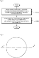
- FIG. 1 is a flowchart for describing a method of preparing a positive active material according to an exemplary embodiment of the present invention
- FIG. 2 is a flowchart for describing a method of preparing a positive active material according to another exemplary embodiment of the present invention
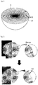
- FIG. 3 is a diagram for describing a positive active material according to an exemplary embodiment of the present invention
- FIG. 4 is a diagram taken along line A-B of FIG. 3
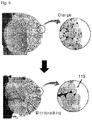
- FIG. 5 is a diagram for describing a stress relaxation effect according to an alignment of primary particles of the positive active material according to the exemplary embodiment of the present invention
- FIG. 6 is a diagram for describing a stress relaxation effect according to an alignment of primary particles of the positive active material according to a comparative example of the present invention.
- a positive active material 100 may include a material in which a compound containing nickel, lithium, and oxygen is doped with boron.
- the positive active material 100 may be the material in which a compound of lithium, nickel, and oxygen is doped with boron, the material in which a compound of lithium, nickel, cobalt, and oxygen is doped with boron, the material in which a compound of lithium, nickel, cobalt, manganese, and oxygen is doped with boron, and the material in which a compound of lithium, nickel, cobalt, aluminum, and oxygen is doped with boron.
- a concentration of boron in the positive active material 100 may be less than 2 mol%. Accordingly, a charge/discharge characteristic and a life-span characteristic of a lithium secondary battery including the positive active material 100 may be improved. In contrast, when the concentration of boron is 2 mol% or more, a charge/discharge characteristic and a life-span characteristic of a lithium secondary battery may deteriorate.
- the concentration of boron may decrease. That is, according to the concentration of nickel in the positive active material 100, the concentration of doped boron may be controlled.
- a concentration of at least one of nickel, cobalt, manganese, and aluminum may be substantially constant in the positive active material 100.
- a concentration of at least one of nickel, cobalt, manganese, and aluminum in the positive active material 100 may have, in a direction from a center of a particle to a surface of the particle, a concentration gradient in the entire particle or a concentration gradient in a part of the particle.
- the positive active material 100 may include a core portion and a shell portion having a different concentration of metal (at least one of nickel, cobalt, manganese, and aluminum) from that of the core portion.
- the positive active material 100 may be represented by Chemical Formula 1 below.
- Chemical Formula 1 Li a M1 x M2 y B z O 2
- M1 is nickel
- M2 may include at least one of aluminum, cobalt, and manganese.
- the positive active material may include primary particles 30 and a secondary particle in which the primary particles 30 are agglomerated. As described above, when boron is doped, boron may be mainly provided on a surface portion of the primary particle 30.
- the primary particles 30 may be extended in a direction in which the primary particles 30 are radiated from one region of an inner portion of the secondary particle to a surface portion 20 of the secondary particle.
- the one region of the inner portion of the secondary particle may be a center portion 10 of the secondary particle. That is, the primary particle 30 may have a rod shape extended from the one region of the inner portion of the secondary particle to the surface portion 20 of the secondary particle.
- the primary particle 30 relatively adjacent to the surface portion 20 of the secondary particle may have a longer length in a direction from the center portion 10 of the inner portion of the secondary particle to the surface portion 20 of the secondary particle than the primary particle 30 relatively adjacent to the center portion of the inner portion 10 of the secondary particle. That is, in at least a part of the secondary particle extended from the center portion 10 to the surface portion 20 of the secondary particle, the lengths of the primary particles 30 may increase as the primary particles 30 are adjacent to the surface portion 20 of the secondary particle.
- the lengths of the primary particles 30 may increase by the doped boron.
- the lengths of the primary particles 30 may be in the direction from the center portion 10 of the secondary particle to the surface portion 20. That is, an aspect ratio corresponding to a ratio of a length value of the primary particle 30 to a width of the primary particle 30 may increase. Accordingly, lithium ions may be easily provided into the secondary particle.
- (003) surface of the primary particle 30 may increase and (014) surface and (104) surface may decrease, and (003) surface of the primary particle 30 may be arranged to be parallel to the direction from the center portion 10 to the surface portion 20 of the secondary particle. That is, an a-axis of a crystal structure of the primary particle 30 may be arranged to be parallel to the direction from the center portion 10 to the surface portion 20 of the secondary particle, and as described above, (003) surface of the primary particle 30 increases by the boron doping, so that the aspect ratio of the primary particle 30 may increase and an orientation property of the primary particle 30 may increase. For example, an average angle of an extension direction of the primary particles 30 located at the outermost portion of the secondary particle and the radiation direction from the center portion to the surface portion of the secondary particle may be 10° or less.
- a movement path of metal ions (for example, lithium ions) and an electrolyte may be provided between the spaces between the primary particles 30 having the rod shapes, that is, the spaces between the primary particles 30 extended in a direction D from the center portion 10 to the surface portion 20 of the secondary particle. Accordingly, charge/discharge efficiency of a secondary battery including the positive active material according to the exemplary embodiment of the present invention may be improved.
- the primary particle may be contracted and expanded in a c-axis. According to the contraction and the expansion of the primary particle in the c-axis, a crack may be generated in the inner portion of the positive active material and the electrolyte may flow into the crack. By a parasitic reaction of the electrolyte flowing through the crack, a NiO-like impurity phase may be formed.
- the primary particle may have a high aspect ratio and have orientation in which the primary particles are arranged in the form radiated from the center of the secondary particle. That is, the a-axis of the primary particles having the high aspect ratio may be highly consistent with the direction radiated from the center of the secondary particle. Accordingly, even though the primary particles are contracted and expanded in the c-axis direction in the charge/discharge process, the arranged primary particles easily relax stress, thereby minimizing the generation of the crack and preventing the Ni-O like impurity phase 110 by the parasitic reaction of the electrolyte from being generated up to the inner portion of the secondary particle.
- the primary particle when boron is not doped, as illustrated in FIG. 6 , the primary particle may have a low aspect ratio and further may have lower orientation radiated from the center of the secondary particle. That is, the a-axis of the primary particles having the low aspect ratio may be little consistent with the direction radiated from the center of the secondary particle (randomly displaced).
- the crack may be easily generated in the inner portion of the secondary particle by stress generated in the contraction and expansion process of the primary particles in the c-axis direction in the charge/discharge process, and accordingly, the Ni-O like impurity phase 110 by the parasitic reaction of the electrolyte is generated up to the inner portion of the secondary particle, thereby degrading a charge/discharge characteristic and a life-span characteristic.
- the a-axis of the primary particles having the high aspect ratio is highly consistent with the direction radiated from the center of the secondary particle, so that the generation of the crack may be minimized during the charge/discharge process, thereby providing the positive active material with the improved charge/discharge capacity and life-span characteristic.
- a positive active material precursor including a hydroxide including nickel of 80 mol% or more is prepared by using a nickel precursor (S110).
- the nickel precursor may be nickel sulfate.
- a cobalt precursor for example, cobalt surface
- manganese precursor for example, manganese surface
- the positive active material precursor may be expressed by Chemical Formula 2 below. ⁇ Chemical Formula 2> [M1 x M2 y ](OH) 2
- M1 is nickel
- M2 may include at least one of cobalt and manganese.
- a positive active material in which a compound containing nickel, lithium, and oxygen is doped with boron, may be prepared by mixing and calcining the positive active material precursor, lithium salt, and a boron precursor (S120).
- the boron precursor may be a boron oxide (B 2 O 3 ).
- the operation of preparing of the positive active material may include mixing and calcining the positive active material precursor, lithium salt, a boron precursor, and an aluminum precursor.
- a positive active material precursor in which a hydroxide including nickel of 79 mol% or more is doped with boron, may be prepared by using a nickel precursor and a boron precursor (S210).
- the nickel precursor may be nickel surface
- a cobalt precursor for example, cobalt surface
- a manganese precursor for example, manganese surface
- the boron precursor may be a boron oxide (B 2 O 3 ).
- the positive active material precursor may be expressed by Chemical Formula 3 below. ⁇ Chemical Formula 3> [M1 x M2 y B z ](OH) 2
- M1 is nickel
- M2 may include at least one of aluminum, cobalt, and manganese.
- a positive active material in which a compound containing nickel, lithium, and oxygen is doped with boron, may be prepared by mixing and calcining the positive active material precursor and lithium salt (S220).
- the preparing of the positive active material may include mixing and calcining the positive active material precursor, lithium salt, and an aluminum precursor.
- Distilled water was added to a co-precipitation reactor and then stirred while N 2 gas was supplied to the reactor.
- a metal aqueous solution in which a molar ratio of nickel sulfate, cobalt sulfate, and manganese sulfate is 60:20:20, and an ammonia aqueous solution were continuously added to the reactor.
- a sodium hydroxide solution was simultaneously supplied for pH adjustment to prepare a [Ni 0.60 Co 0.20 Mn 0.20 ](OH) 2 metal composite hydroxide.
- the prepared [Ni 0.60 Co 0.20 Mn 0.20 ](OH) 2 metal composite hydroxide was washed with water, filtered, and then dried at a vacuum drier at 110°C.
- the metal composite hydroxide and a lithium hydroxide (LiOH) were mixed at a molar ratio of 1:1.01 and then calcined at 850°C in an oxygen atmosphere to prepare Li[Ni 0.60 Co 0.20 Mn 0.20 ]O 2 positive active material powder.
- Distilled water was added to a co-precipitation reactor and then stirred while N 2 gas was supplied to the reactor.
- a metal aqueous solution in which a molar ratio of nickel sulfate, cobalt sulfate, and manganese sulfate is 60:20:20, and an ammonia aqueous solution were continuously added to the reactor.
- a sodium hydroxide solution was simultaneously supplied for pH adjustment to prepare a [Ni 0.60 Co 0.20 Mn 0.20 ](OH) 2 metal composite hydroxide.
- the prepared [Ni 0.60 Co 0.20 Mn 0.20 ](OH) 2 metal composite hydroxide was washed with water, filtered, and then dried at a vacuum drier at 110°C.
- the metal composite hydroxide, a boron oxide (B 2 O 3 ), and a lithium hydroxide (LiOH) were mixed at a molar ratio of 0.99:0.005:1.01 and then calcined at 850°C in an oxygen atmosphere to prepare Li[Ni 0.59 Co 0.20 Mn 0.20 B 0.01 ]O 2 positive active material powder.
- Distilled water was added to a co-precipitation reactor and then stirred while N 2 gas was supplied to the reactor.
- a metal aqueous solution in which a molar ratio of nickel sulfate, cobalt sulfate, and manganese sulfate is 70:15:15, and an ammonia aqueous solution were continuously added to the reactor.
- a sodium hydroxide solution was simultaneously supplied for pH adjustment to prepare a [Ni 0.70 Co 0.15 Mn 0.15 ](OH) 2 metal composite hydroxide.
- the prepared [Ni 0.70 Co 0.15 Mn 0.15 ](OH) 2 metal composite hydroxide was washed with water, filtered, and then dried at a vacuum drier at 110°C.
- the metal composite hydroxide and a lithium hydroxide (LiOH) were mixed at a molar ratio of 1:1.01 and then calcined at 800 °C in an oxygen atmosphere to prepare Li[Ni 0.70 Co 0.15 Mn 0.15 ]O 2 positive active material powder.
- Distilled water was added to a co-precipitation reactor and then stirred while N 2 gas was supplied to the reactor.
- a metal aqueous solution in which a molar ratio of nickel sulfate, cobalt sulfate, and manganese sulfate is 70:15:15, and an ammonia aqueous solution were continuously added to the reactor.
- a sodium hydroxide solution was simultaneously supplied for pH adjustment to prepare a [Ni 0.70 Co 0.15 Mn 0.15 ](OH) 2 metal composite hydroxide.
- the prepared [Ni 0.70 Co 0.15 Mn 0.15 ](OH) 2 metal composite hydroxide was washed with water, filtered, and then dried at a vacuum drier at 110°C.
- the metal composite hydroxide, a boron oxide (B 2 O 3 ), and a lithium hydroxide (LiOH) were mixed at a molar ratio of 0.99:0.005:1.01 and then calcined at 800 °C in an oxygen atmosphere to prepare Li[Ni 0.69 Co 0.15 Mn 0.15 B 0.01 ]O 2 positive active material powder.
- Distilled water was added to a co-precipitation reactor and then stirred while N 2 gas was supplied to the reactor.
- a metal aqueous solution in which a molar ratio of nickel sulfate and cobalt sulfate is 83:17, and an ammonia aqueous solution were continuously added to the reactor.
- a sodium hydroxide solution was supplied for pH adjustment to prepare a [Ni 0.83 Co 0.17 ](OH) 2 metal composite hydroxide.
- the prepared [Ni 0.83 Co 0.17 ](OH) 2 metal composite hydroxide was washed with water, filtered, and then dried at a vacuum drier at 110°C.
- the metal composite hydroxide, an aluminum hydroxide (Al(OH) 3 ), and a lithium hydroxide (LiOH) were mixed at a molar ratio of 0.96:0.04:1.01 and then calcined at 750°C in an oxygen atmosphere to prepare Li[Ni 0.80 Co 0.16 Al 0.04 ]O 2 positive active material powder.
- Distilled water was added to a co-precipitation reactor and then stirred while N 2 gas was supplied to the reactor.
- a metal aqueous solution in which a molar ratio of nickel sulfate and cobalt sulfate is 83:17, and an ammonia aqueous solution were continuously added to the reactor.
- a sodium hydroxide solution was supplied for pH adjustment to prepare a [Ni 0.83 Co 0.17 ](OH) 2 metal composite hydroxide.
- the prepared [Ni 0.83 Co 0.17 ](OH) 2 metal composite hydroxide was washed with water, filtered, and then dried at a vacuum drier at 110°C.
- the metal composite hydroxide, a boron oxide (B 2 O 3 ), an aluminum oxide (Al(OH) 3 ), and a lithium hydroxide (LiOH) were mixed at a molar ratio of 0.95:0.005:0.04:1.01 and then calcined at 750°C in an oxygen atmosphere to prepare Li[Ni 0.79 Co 0.16 Al 0.04 B 0.01 ]O 2 positive active material powder.
- Distilled water was added to a co-precipitation reactor and then stirred while N 2 gas was supplied to the reactor.
- a metal aqueous solution in which a molar ratio of nickel sulfate and cobalt sulfate is 90:10, and an ammonia aqueous solution were continuously added to the reactor.
- a sodium hydroxide solution was supplied for pH adjustment to prepare a [Ni 0.90 Co 0.10 ](OH) 2 metal composite hydroxide.
- the prepared [Ni 0.90 Co 0.10 ](OH) 2 metal composite hydroxide was washed with water, filtered, and then dried at a vacuum drier at 110°C.
- the metal composite hydroxide, an aluminum hydroxide (Al(OH) 3 ), and a lithium hydroxide (LiOH) were mixed at a molar ratio of 0.985:0.015:1.01 and then calcined at 730°C in an oxygen atmosphere to prepare Li[Ni 0.885 Co 0.10 Al 0.015 ]O 2 positive active material powder.
- Distilled water was added to a co-precipitation reactor and then stirred while N 2 gas was supplied to the reactor.
- a metal aqueous solution in which a molar ratio of nickel sulfate and cobalt sulfate is 90:10, and an ammonia aqueous solution were continuously added to the reactor.
- a sodium hydroxide solution was supplied for pH adjustment to prepare a [Ni 0.90 Co 0.10 ](OH) 2 metal composite hydroxide.
- the prepared [Ni 0.90 Co 0.10 ](OH) 2 metal composite hydroxide was washed with water, filtered, and then dried at a vacuum drier at 110°C.
- the metal composite hydroxide, a boron oxide (B 2 O 3 ), an aluminum oxide (Al(OH) 3 ), and a lithium hydroxide (LiOH) were mixed at a molar ratio of 0.975:0.005:0.015:1.01 and then calcined at 730°C in an oxygen atmosphere to prepare Li[Ni 0.875 Co 0.10 Al 0.015 B 0.01 ]O 2 positive active material powder.
- Distilled water was added to a co-precipitation reactor and then stirred while N 2 gas was supplied to the reactor.
- a metal aqueous solution in which a molar ratio of nickel sulfate and cobalt sulfate is 90:10, and an ammonia aqueous solution were continuously added to the reactor.
- a sodium hydroxide solution was supplied for pH adjustment to prepare a [Ni 0.90 Co 0.10 ](OH) 2 metal composite hydroxide.
- the prepared [Ni 0.90 Co 0.10 ](OH) 2 metal composite hydroxide was washed with water, filtered, and then dried at a vacuum drier at 110°C.
- the metal composite hydroxide, a boron oxide (B 2 O 3 ), an aluminum oxide (Al(OH) 3 ), and a lithium hydroxide (LiOH) were mixed at a molar ratio of 0.965:0.01:0.015:1.01 and then calcined at 730°C in an oxygen atmosphere to prepare Li[Ni 0.865 Co 0.10 Al 0.015 B 0.02 ]O 2 positive active material powder.
- Distilled water was added to a co-precipitation reactor and then stirred while N 2 gas was supplied to the reactor.
- a metal aqueous solution in which a molar ratio of nickel sulfate, cobalt sulfate, and manganese sulfate is 90:5:5, and an ammonia aqueous solution were continuously added to the reactor.
- a sodium hydroxide solution was simultaneously supplied for pH adjustment to prepare a [Ni 0.90 Co 0.05 Mn 0.05 ](OH) 2 metal composite hydroxide.
- the prepared [Ni 0.90 Co 0.05 Mn 0.05 ](OH) 2 metal composite hydroxide was washed with water, filtered, and then dried at a vacuum drier at 110°C.
- the metal composite hydroxide and a lithium hydroxide (LiOH) were mixed at a molar ratio of 1:1.01 and then calcined at 750°C in an oxygen atmosphere to prepare Li[Ni 0.90 Co 0.05 Mn 0.05 ]O 2 positive active material powder.
- Distilled water was added to a co-precipitation reactor and then stirred while N 2 gas was supplied to the reactor.
- a metal aqueous solution in which a molar ratio of nickel sulfate, cobalt sulfate, and manganese sulfate is 90:5:5, and an ammonia aqueous solution were continuously added to the reactor.
- a sodium hydroxide solution was supplied for pH adjustment to prepare a [Ni 0.90 Co 0.05 Mn 0.05 ](OH) 2 metal composite hydroxide.
- the prepared [Ni 0.90 Co 0.05 Mn 0.05 ](OH) 2 metal composite hydroxide was washed with water, filtered, and then dried at a vacuum drier at 110°C.
- the metal composite hydroxide, a boron oxide (B 2 O 3 ), and a lithium hydroxide (LiOH) were mixed at a molar ratio of 0.996:0.002:1.01 and then calcined at 750°C in an oxygen atmosphere to prepare Li[Ni 0.896 Co 0.05 Mn 0.05 B 0.004 ]O 2 positive active material powder.
- Distilled water was added to a co-precipitation reactor and then stirred while N 2 gas was supplied to the reactor.
- a metal aqueous solution in which a molar ratio of nickel sulfate, cobalt sulfate, and manganese sulfate is 90:5:5, and an ammonia aqueous solution were continuously added to the reactor.
- a sodium hydroxide solution was supplied for pH adjustment to prepare a [Ni 0.90 Co 0.05 Mn 0.05 ](OH) 2 metal composite hydroxide.
- the prepared [Ni 0.90 Co 0.05 Mn 0.05 ](OH) 2 metal composite hydroxide was washed with water, filtered, and then dried at a vacuum drier at 110°C.
- the metal composite hydroxide, a boron oxide (B 2 O 3 ), and a lithium hydroxide (LiOH) were mixed at a molar ratio of 0.99:0.005:1.01 and then calcined at 750°C in an oxygen atmosphere to prepare Li[Ni 0.89 Co 0.05 Mn 0.05 B 0.01 ]O 2 positive active material powder.
- Distilled water was added to a co-precipitation reactor and then stirred while N 2 gas was supplied to the reactor.
- a metal aqueous solution in which a molar ratio of nickel sulfate, cobalt sulfate, and manganese sulfate is 90:5:5, and an ammonia aqueous solution were continuously added to the reactor.
- a sodium hydroxide solution was supplied for pH adjustment to prepare a [Ni 0.90 Co 0.05 Mn 0.05 ](OH) 2 metal composite hydroxide.
- the prepared [Ni 0.90 Co 0.05 Mn 0.05 ](OH) 2 metal composite hydroxide was washed with water, filtered, and then dried at a vacuum drier at 110°C.
- the metal composite hydroxide, a boron oxide (B 2 O 3 ), and a lithium hydroxide (LiOH) were mixed at a molar ratio of 0.98:0.01:1.01 and then calcined at 750°C in an oxygen atmosphere to prepare Li[Ni 0.88 Co 0.05 Mn 0.05 B 0.02 ]O 2 positive active material powder.
- Distilled water was added to a co-precipitation reactor and then stirred while N 2 gas was supplied to the reactor.
- a metal aqueous solution in which a molar ratio of nickel sulfate and cobalt sulfate is 96:4, and an ammonia aqueous solution were continuously added to the reactor.
- a sodium hydroxide solution was simultaneously supplied for pH adjustment to prepare a [Ni 0.96 Co 0.04 ](OH) 2 metal composite hydroxide.
- the prepared [Ni 0.96 Co 0.04 ](OH) 2 metal composite hydroxide was washed with water, filtered, and then dried at a vacuum drier at 110°C.
- the metal composite hydroxide, an aluminum hydroxide (Al(OH) 3 ), and a lithium hydroxide (LiOH) were mixed at a molar ratio of 0.99:0.01:1.01 and then calcined at 730°C in an oxygen atmosphere to prepare Li[Ni 0.95 Co 0.04 Al 0.01 ]O 2 positive active material powder.
- Distilled water was added to a co-precipitation reactor and then stirred while N 2 gas was supplied to the reactor.
- a metal aqueous solution in which a molar ratio of nickel sulfate and cobalt sulfate is 96:4, and an ammonia aqueous solution were continuously added to the reactor.
- a sodium hydroxide solution was supplied for pH adjustment to prepare a [Ni 0.96 Co 0.04 ](OH) 2 metal composite hydroxide.
- the prepared [Ni 0.96 Co 0.04 ](OH) 2 metal composite hydroxide was washed with water, filtered, and then dried at a vacuum drier at 110°C.
- the metal composite hydroxide, a boron oxide (B 2 O 3 ), an aluminum oxide (Al(OH) 3 ), and a lithium hydroxide (LiOH) were mixed at a molar ratio of 0.98:0.005:0.01:1.01 and then calcined at 730°C in an oxygen atmosphere to obtain Li[Ni 0.94 Co 0.04 Al 0.01 B 0.01 ]O 2 positive active material powder.
- Distilled water was added to a co-precipitation reactor and then stirred while N 2 gas was supplied to the reactor.
- a metal aqueous solution in which a molar ratio of nickel sulfate and cobalt sulfate is 90:10, and an ammonia aqueous solution were continuously added to the reactor.
- a sodium hydroxide solution in which a boron oxide (B 2 O 3 ) was dissolved by 0.01 M, was simultaneously supplied for pH adjustment and the boron doping to prepare a [Ni 0.895 Co 0.10 B 0.005 ](OH) 2 metal composite hydroxide.
- the prepared [Ni 0.895 Co 0.10 B 0.005 ](OH) 2 metal composite hydroxide was washed with water, filtered, and then dried at a vacuum drier at 110°C.
- the metal composite hydroxide and a lithium hydroxide (LiOH) were mixed at a molar ratio of 1:1.01 and then calcined at 730°C in an oxygen atmosphere to prepare Li[Ni 0.895 Co 0.10 B 0.005 ]O 2 positive active material powder.
- Distilled water was added to a co-precipitation reactor and then stirred while N 2 gas was supplied to the reactor.
- a metal aqueous solution in which a molar ratio of nickel sulfate and cobalt sulfate is 90:10, and an ammonia aqueous solution were continuously added to the reactor.
- a sodium hydroxide solution in which a boron oxide (B 2 O 3 ) was dissolved by 0.02 M, was simultaneously supplied for pH adjustment and the boron doping to prepare a [Ni 0.89 Co 010 B 0.01 ](OH) 2 metal composite hydroxide.
- the prepared [Ni 0.89 Co 0.10 B 0.01 ](OH) 2 metal composite hydroxide was washed with water, filtered, and then dried at a vacuum drier at 110°C.
- the metal composite hydroxide and a lithium hydroxide (LiOH) were mixed at a molar ratio of 1:1.01 and then calcined at 730°C in an oxygen atmosphere to prepare Li[Ni 0.89 Co 0.10 B 0.01 ]O 2 positive active material powder.
- Distilled water was added to a co-precipitation reactor and then stirred while N 2 gas was supplied to the reactor.
- a metal aqueous solution in which a molar ratio of nickel sulfate and cobalt sulfate is 90:10, and an ammonia aqueous solution were continuously added to the reactor.
- a sodium hydroxide solution in which a boron oxide (B 2 O 3 ) was dissolved by 0.04 M, was simultaneously supplied for pH adjustment and the boron doping to prepare a [Ni 0.88 Co 0.10 B 0.02 ](OH) 2 metal composite hydroxide.
- the prepared [Ni 0.88 Co 0.10 B 0.02 ](OH) 2 metal composite hydroxide was washed with water, filtered, and then dried at a vacuum drier at 110°C.
- the metal composite hydroxide and a lithium hydroxide (LiOH) were mixed at a molar ratio of 1:1.01 and then calcined at 730°C in an oxygen atmosphere to prepare Li[Ni 0.88 Co 0.10 B 0.02 ]O 2 positive active material powder.
- Distilled water was added to a co-precipitation reactor and then stirred while N 2 gas was supplied to the reactor.
- a metal aqueous solution in which a molar ratio of nickel sulfate and cobalt sulfate is 90:10, and an ammonia aqueous solution were continuously added to the reactor.
- a sodium hydroxide solution in which a boron oxide (B 2 O 3 ) was dissolved by 0.01 M, was simultaneously supplied for pH adjustment and the boron doping to prepare a [Ni 0.895 Co 0.10 B 0.005 ](OH) 2 metal composite hydroxide.
- the prepared [Ni 0.895 Co 0.10 B 0.005 ](OH) 2 metal composite hydroxide was washed with water, filtered, and then dried at a vacuum drier at 110°C.
- the metal composite hydroxide, an aluminum hydroxide (Al(OH) 3 ), and a lithium hydroxide (LiOH) were mixed at a molar ratio of 0.985:0.015:1.01 and then calcined at 730°C in an oxygen atmosphere to prepare Li[Ni 0.88 Co 0.10 Al 0.015 B 0.005 ]O 2 positive active material powder.
- Distilled water was added to a co-precipitation reactor and then stirred while N 2 gas was supplied to the reactor.
- a metal aqueous solution in which a molar ratio of nickel sulfate and cobalt sulfate is 90:10, and an ammonia aqueous solution were continuously added to the reactor.
- a sodium hydroxide solution in which a boron oxide (B 2 O 3 ) was dissolved by 0.02 M, was simultaneously supplied for pH adjustment and the boron doping to prepare a [Ni 0.89 Co 010 B 0.01 ](OH) 2 metal composite hydroxide.
- the prepared [Ni 0.89 Co 010 B 0.01 ](OH) 2 metal composite hydroxide was washed with water, filtered, and then dried at a vacuum drier at 110°C.
- the metal composite hydroxide, an aluminum hydroxide (Al(OH) 3 ), and a lithium hydroxide (LiOH) were mixed at a molar ratio of 0.985:0.015:1.01 and then calcined at 730°C in an oxygen atmosphere to prepare Li[Ni 0.875 Co 0.10 Al 0.015 B 0.01 ]O 2 positive active material powder.
- Distilled water was added to a co-precipitation reactor and then stirred while N 2 gas was supplied to the reactor.
- a metal aqueous solution in which a molar ratio of nickel sulfate and cobalt sulfate is 90:10, and an ammonia aqueous solution were continuously added to the reactor.
- a sodium hydroxide solution in which a boron oxide (B 2 O 3 ) was dissolved by 0.04 M, was simultaneously supplied for pH adjustment and the boron doping to prepare a [Ni 0.88 Co 0.10 B 0.02 ](OH) 2 metal composite hydroxide.
- the prepared [Ni 0.88 Co 0.10 B 0.02 ](OH) 2 metal composite hydroxide was washed with water, filtered, and then dried at a vacuum drier at 110°C.
- the metal composite hydroxide, an aluminum hydroxide (Al(OH) 3 ), and a lithium hydroxide (LiOH) were mixed at a molar ratio of 0.985:0.015:1.01 and then calcined at 730°C in an oxygen atmosphere to prepare Li[Ni 0.865 Co 0.10 Al 0.015 B 0.02 ]O 2 positive active material powder.
- WO 3 powder was dissolved in a lithium hydroxide solution at a concentration of 0.47 M.
- a metal aqueous solution, in which a molar ratio of nickel sulfate, cobalt sulfate, and manganese sulfate is 90:5:5, and an ammonia solution were continuously added to the reactor.
- the basic aqueous solution, in which W was dissolved was supplied for pH adjustment and the addition of tungsten to prepare a [Ni 0.89 Co 0.05 Mn 0.05 W 0.01 ](OH) 2 metal composite hydroxide.
- the prepared [Ni 0.89 Co 0.05 Mn 0.05 W 0.01 ](OH) 2 metal composite hydroxide was washed with water, filtered, and then dried at a vacuum drier at 110°C for 12 hours.
- the metal composite hydroxide and a lithium hydroxide (LiOH) were mixed at a molar ratio of 1:1.01 and then calcined at 770°C in an oxygen atmosphere to obtain Li[Ni 0.89 Co 0.05 Mn 0.05 W 0.01 ]O 2 positive active material powder.
- compositions (mol%) of the positive active materials according to the Examples and the Comparative Examples of the present invention are represented in the table below.
- FIG. 7 is a graph illustrating XRD results of positive active materials according to Examples 1-5-1 and 1-5-2, and Comparative Example 1-5 of the present invention.
- FIG. 7A to 7C XRD results of positive active materials according to Comparative Example 1-5, Examples 1-5-1 and 1-5-2 of the present invention were measured.
- FIGS. 7A to 7C are the graphs illustrating XRD results of the positive active materials according to Comparative Example 1-5 and Examples 1-5-1 and 1-5-2 of the present invention, respectively.
- Lattice constants and unit cell volumes of the positive active material according to Comparative Example 1-5 and the positive active material according to Examples 1-5-1 and 1-5-2 are represented in Table 4 below. It can be seen that even though an ion radius of boron is small, a lattice constant increases according to an increase in the amount of boron doped. Further, it can be seen that a volume of a unit cell gradually increases according to a doping concentration of boron. [Table 4] a-axis ( ⁇ ) c-axis ( ⁇ ) Volume ( ⁇ ) Comparative Example 1-5 2.8740 14.1997 101.577 Example 1-5-1 2.8751 14.2020 101.672 Example 1-5-2 2.8764 14.2049 101.779
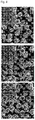
- FIG. 8 is a Scanning Electron Microscope (SEM) picture of the positive active materials according to Comparative Example 1-5 and Examples 1-5-1 and 1-5-2 of the present invention
- FIG. 9 is a Scanning Transmission Electron Microscope (STEM) picture of the positive active materials according to Comparative Example 1-5 and Examples 1-5-2 of the present invention
- FIG. 10 is an enlarged TEM picture and a diagram for describing an ED pattern and a crystal structure of the positive active material according to Example 1-5-2 of the present invention.
- FIGS. 8 to 10 (a) to (c) of FIG. 8 are SEM pictures of the positive active material according to Comparative Example 1-5 and Examples 1-5-1 and 1-5-2, respectively
- (d) and (e) of FIG. 9 are STEM pictures of the positive active material according to Comparative Example 1-5 and Example 1-5-2, respectively.
- the positive active material has the form of the secondary particle in which the plurality of primary particles having the rod shape is agglomerated, and an aspect ratio and arrangement of the primary particles are improved according to the boron doping.
- An aspect ratio of the primary particle of the positive active material according to Comparative Example 1-5 was 2.0 and an average length was 0.55 ⁇ m
- an aspect ratio of the primary particle of the positive active material according to Example 1-5-1 was 4.1 and an average length was 1.0 ⁇ m
- an aspect ratio of the primary particle of the positive active material according to Example 1-5-2 was 9.0 and an average length was 1.1 ⁇ m, which were calculated through the TEM pictures.
- FIG. 10 it can be seen that the a-axis of the primary particle is substantially parallel to the radius direction of the secondary particle, and each of the surfaces of the layers including Li ions of the primary particles heads the center of the secondary particle.
- An electron diffraction of the primary particles around the secondary particle indexed with 100 region of R 3 ⁇ m is shown and [h00] direction heads the center of the secondary particle.
- the Li plane may be substantially parallel to the direction from the center to the surface of the particle.
- FIG. 11 is a graph for describing surface energy of the positive active material doped with boron according to Examples of the present invention
- FIGS. 12 to 15 are diagrams illustrating a structural model of the positive active material doped with boron according to the Examples of the present invention.
- a crystallographic structure observed in the positive active material doped with boron may be derived according to surface energy reforming of the primary particle and a change in a shape of the primary particle according to the surface energy reforming. That is, crystal morphology may be generally determined by a relative size of surface energy. For example, a spherical crystal structure is formed by isotropic surface energy, a surface having high energy is mainly removed during crystal growth by anisotropic surface energy, and a final crystal shape may be determined by relative orientation of a surface of the remaining low energy.
- the (003) and (104) surfaces may have lowest surface energy, and for example, a flat hexagonal plate (especially, in an oxidizing environment) prefers (003) surface and the (003) surface may be dominantly formed.
- the crystal structure may be changed from the flat plate to a cube shape.
- the primary particle of the positive active material in which boron is not doped mainly includes the (104) surface as the surface, but the primary particle of the positive active material in which boron is doped may include the (003) surface having a relative large area.
- DFT was used for calculating energy of the (003) and (104) surfaces in LiNiO 2 and boron-doped LiNiO 2 , and the amount of Ni in the positive active material including Ni of 90 mol% is similar to the amount of Ni in LiNiO 2 , and even though Ni is substituted with Mn by 10%, the surface energy of the (003) surface is not substantially changed, so that LiNiO 2 was used as a model structure for simplifying the calculation.
- an Ni site is a position advantageous to boron doping ( FIG. 15 ), which is because B moves to the O layer combined with three O negative ions.
- FIG. 11 represents surface energy plot ⁇ ( ⁇ Li ) of the (003) and (104) surfaces of LiNiO 2 in which boron is not doped and boron-doped LiNiO 2 as a function of chemical potential ( ⁇ Li ) of Li to bulk metal Li.
- a small (large) value of ( ⁇ Li ) represents an environment in which Li is poor (rich), and the case where ( ⁇ Li ) is 0 represents that the lithium metal is reserved.
- a horizontal line and an inclined line of FIG. 11 are the values of ⁇ ( ⁇ Li ) calculated to the stoichiometric surface and the non-stoichiometric surface, respectively.
- the (003) surface is very advantageous to the surface, in the boron-doped stoichiometric LiNiO 2 , in which -2.73eV ⁇ ⁇ Li ⁇ -1.53eV, the (104) surface is stable as the surface.
- the (003) surface has the most advantageous structure as the surface.
- the structure by the DFT calculation presents the formation of the well-aligned surface in the lithium boron oxide structure.
- a B dopant is located in the second layer, but moves to the topmost layer (of the Li layer) according to the stabilization of the structure. Further, the B dopant pulls and moves O negative ions from the second layer to the topmost layer, and in order to provide a sufficient space to the O negative ions, the Li surface is locally bent.
- model c an average combination length between B and O is 1.384, and the theoretical calculation shows that the (003) surface is stabilized in the surface in which LiNiO 2 , particularly, Li is rich.
- Li when lithiumization with a hydroxide precursor containing 90 mol% of Ni is performed by enriched Li, Li may be rich on the surface of the boron-doped particle and energy of (003) surface may be preferentially decreased by the B atom. Accordingly, the plurality of primary particles having developed (003) surface may be provided.
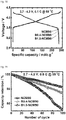
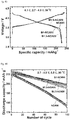
- FIG. 16 is a graph illustrating capacity characteristics of lithium secondary batteries including positive active materials according to Comparative Example 1-5 and Examples 1-5-1 to 1-5-3 of the present invention measured at 30°C
- FIG. 17 is a graph illustrating life-span characteristics of lithium secondary batteries including the positive active materials according to Comparative Example 1-5 and Examples 1-5-1 to 1-5-3 of the present invention measured at 30°C
- FIG. 18 is a graph illustrating capacity characteristics of lithium secondary batteries including the positive active materials according to Comparative Example 1-5 and Examples 1-5-1 and 1-5-2 of the present invention measured at 55°C
- FIG. 19 is a graph illustrating life-span characteristics of the lithium secondary batteries including the positive active materials according to Comparative Example 1-5 and Examples 1-5-1 and 1-5-2 of the present invention measured at 55°C.
- half cells were manufactured by using the positive active materials according to Comparative Example 1-5, and Examples 1-5-1 to 1-5-3, a discharge capacity was measured under the condition of cut off 2.7 to 4.3V, 0.1C, and temperatures of 30°C and 50°C, and a capacity change according to the number of times of the charge/discharge cycle was measured under the condition of cut off 2.7 to 4.3V, 0.5C, and temperatures of 30°C and 50°C.
- NCM90 means the positive active material according to Comparative Example 1-5
- B0.4-NCM90 means the positive active material according to Example 1-5-1
- B1.0-NCM90 means the positive active material according to Example 1-5-2
- B2.0-NCM90 means the positive active material according to Example 1-5-3.
- the amount of boron doped in the positive active material is 2.0 mol% or more, the life-span characteristic is decreased again. That is, it can be seen that the control of the amount of boron doped to be less than 2.0 mol% is the effective method of improving the life-span characteristic of the lithium secondary battery using the high-nickel positive active material.
- FIGS. 20A and 20B are graphs illustrating differential capacities of the lithium secondary batteries including the positive active materials according to Comparative Example 1-5 and Example 1-5-2 of the present invention measured at 55°C
- FIGS. 21A , 21B, and 21C are graphs illustrating differential capacities of the lithium secondary batteries including the positive active materials according to Comparative Example 1-5 and Examples 1-5-1 and 1-5-2 of the present invention measured at 30°C.
- FIGS. 20 and 21 as described above, half cells were manufactured by using the positive active materials according to Comparative Example 1-5 and Example 1-5-1 and 1-5-2, a differential capacity according to the number of times of the charge/discharge was measured under the condition of cut off 2.7 to 4.3V and temperatures of 30°C and 55°C.
- FIGS. 20A and 20B are the differential capacity graphs (the condition of 55°C) for the positive active materials according to Comparative Example 1-5 and Example 1-5-2
- FIGS. 21A to 21C are differential capacity graphs for the positive active materials according to Comparative Example 1-5 and Examples 1-5-1 and 1-5-2 (the condition of 30°C).
- the positive active materials according to Examples 1-5-1 and 1-5-2 and Comparative Example 1 sequentially include H1 phase, H1+M phase, M phase, M+H2 phase, H2 phase, H2+H3 phase, H3 phase, H2+H3 phase, M+H2 phase, M phase, H1+M phase, and H1 phase.
- H1 phase H1+M phase
- M phase M+H2 phase
- H2+H3 phase H3 phase
- H2+H3 phase H2+H3 phase
- M+H2 phase M phase
- H1+M phase H1+M phase
- the H1 phase represents the crystal structure in which the positive active materials according to the Examples and the Comparative Example have unique lattice constants in the c-axis direction
- the H2 phase represents the crystal structure in which the positive active materials according to the Examples and the Comparative Example have lattice constants longer than the unique lattice constants in the c-axis direction
- the H3 phase represents the crystal structure in which the positive active materials according to the Examples and the Comparative Example have lattice constants shorter than the unique lattice constants in the c-axis direction
- the M phase represents the monoclinic crystal structure.
- Comparative Example 1-5 in which boron is not doped, as illustrated in FIGS. 20 and 21 , it can be seen that according to the increase in the number of times of the charge/discharge, the peak values of the H2 and H3 phases are sharply decreased.
- the phase transition from H2 to H3 causes the rapid contraction of the unit cell in the c-axis direction to mechanically transform the positive active material, thereby decreasing the life-span characteristic. That is, it can be seen again that in the range of 4.1 to 4.3 V, the integral area rapidly decreases, and as described above, according to Comparative Example 1-5, the capacity rapidly decreases according to the number of times of the charge/discharge.
- FIG. 22 is a SEM picture of the positive active materials according to Comparative Example 1-5 and Examples 1-5-2 of the present invention.
- FIG. 22 half cells were manufactured by using the positive active materials according to Comparative Example 1-5 and Example 1-5-2, and a SEM picture of the positive active materials was taken after 100 times of the charge/discharge.
- (c) and (d) of FIG. 22 are SEM pictures of the positive active materials according to Comparative Example 1-5 and Examples 1-5-2 of the present invention.
- FIG. 23 is a graph illustrating an XRD measurement result after the positive active materials according to Comparative Example 1-5 and Example 1-5-2 of the present invention are charged
- FIG. 24 is a graph for describing a change in an a-axis length and a c-axis length before and after the positive active materials according to Comparative Example 1-5 and Example 1-5-2 of the present invention are charged.
- the microcrack shown in the charge state of the positive active material is generally due to the anisotropic dimensional change of the unit cell, in order to quantify the unit cell, an ex situ XRD measurement was performed on the positive active materials according to Comparative Example 1-5 and Example 1-5-2 in the charge state, and the changes in an a-axis length and a c-axis length before and after the positive active materials according to Comparative Example 1-5 and Example 1-5-2 of the present invention are charged were measured.
- NCM90 means the positive active material according to Comparative Example 1-5 and B1.0-NCM90 means the positive active material according to Example 1-5-2.
- the c-axis lattice constant was decreased by 5.1% in the case of the positive active material according to Example 1-5-2, and the c-axis lattice constant was decreased by 5.9% in the case of the positive active material according to Comparative Example 1-5. It can be seen that the positive active material according to Example 1-5-2 is decreased compared to the positive active material according to Comparative Example 1-5.
- anisotropic stress within the primary particle causes transformation in a boundary between the particles to generate microcrack in the boundary, and finally the primary particle may be separated an electrolyte may permeate into the microcrack within the particle, thereby degrading the positive active material.
- the primary particles arranged so that the a-axis direction heads the center portion of the secondary particle may be agglomerated, and as a result, the primary particles aligned in the radius direction may uniformly contract the entire secondary particle without the local stress concentration. Accordingly, it is possible to minimize the generation of the microcrack within the secondary particle.
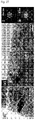
- FIG. 25 is a STEM picture of the positive active materials according to Comparative Example 1-5 and Examples 1-5-1 and 1-5-2 of the present invention of which charge/discharge is performed 100 times
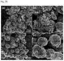
- FIG. 26 is a SEM picture of the positive active materials after the lithium secondary batteries including the positive active materials according to Comparative Example 1-5 and Examples 1-5-1 and 1-5-2 of the present invention, of which charge/discharge is performed 100 times, are charged/discharged 100 times
- FIG. 27 is an enlarged TEM picture of the positive active material according to Comparative Example 1-5 of which charge/discharge is performed 100 times, and a FFT diagram for zones I and II, and FIGS.
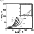
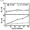
- 28A, 28B , 28C , and 28D are a diagram illustrating an equivalent circuit of a Nyquist plot, and graphs illustrating a comparison of R sf and R ct of the positive active materials according to Comparative Example 1-5 and Example 1-5-2.
- FIGS. 25 to 27 are STEM pictures of the positive active materials according to Comparative Example 1-5 and Examples 1-5-1 and 1-5-2 of which charge/discharge is performed 100 times at 55°C, respectively
- (a) and (b) of FIG. 26 are SEM pictures of the positive active material according to Comparative Example 1-5 of which charge/discharge is performed 100 times at 55°C
- (c) and (d) of FIG. 26 are SEM pictures of the positive active material according to Example 1-5-2 of which charge/discharge is performed 100 times at 55°C
- (b) and (c) of FIG. 28 are graphs illustrating the EIS result of the positive active materials according to Comparative Example 1-5 and Example 1-5-2 according to the number of times of the charge/discharge, respectively.
- NCM90 means the positive active material according to Comparative Example 1-5
- B0.4-NCM90 means the positive active material according to Example 1-5-1
- B1.0-NCM90 means the positive active material according to Example 1-5-2.
- the positive active material according to Comparative Example 1-5 of which the charge/discharge is performed includes a network structure of the microcrack which is formed along the interface between the particles and separates the primary particles. As illustrated in FIG. 26 , it can be seen that in the positive active material according to Comparative Example 1-5, the plurality of microcracks is generated according to the performance of the charge/discharge, but in the boron-doped positive active material according to Example 1-5-2, the generation of the microcrack according to the performance of the charge/discharge is significantly little.
- the positive active material according to Comparative Example 1-5 includes the primary particle of which the aspect ratio is relatively low, and as a result, the plurality of microcracks may be generated by the contraction and the expansion generated during the charge/discharge process, and the positive active material may be degraded by the parasitic reaction with the electrolyte permeating into the microcrack. That is, as illustrated in FIG.
- charge movement resistance (R ct ) of the positive active material according to Comparative Example 1-5 gradually increases from 11.7 ⁇ (the first cycle) to 79.2 ⁇ (100 th cycle), but R ct of the positive active material according to Example 1-5-2 increases from 13.1 ⁇ (the first cycle) to 22.6 ⁇ (100 th cycle) and thus the increase amount is remarkably small. That is, it can be seen that a resistance increase layer becomes thick inside the positive active material according to Comparative Example 1-5.
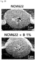
- FIG. 29 is SEM pictures of positive active materials according to Comparative Example 1-1 and Example 1-1 of the present invention
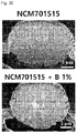
- FIG. 30 is SEM pictures of positive active materials according to Comparative Example 1-2 and Example 1-2 of the present invention
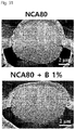
- FIG. 31 is SEM pictures of positive active materials according to Comparative Example 1-3 and Example 1-3 of the present invention
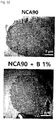
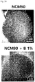
- FIG. 32 is TEM picture of positive active materials according to Comparative Example 1-4 and Example 1-4-1 of the present invention
- FIG. 33 is TEM pictures of positive active materials according to Comparative Example 1-5 and Example 1-5-2 of the present invention
- FIG. 34 is a graph illustrating an evaluated arrangement property of the primary particle according to the content of nickel in the positive active materials according to Examples and Comparative Examples of the present invention.
- SEM pictures and TEM pictures of the positive active materials according to Comparative Examples 1-1 to 1-5 and Examples 1-1 to 1-3, Example 1-4-1, and Example 1-5-2 were taken.
- the arrangement property of the primary particle was measured by using the SEM pictures and the TEM pictures. Particularly, an average angle (°) according to a nickel concentration (mol%) was measured by measuring a clearance angle between the radiation direction from the center portion of the particle to the surface of the particle and an extension direction of the outermost primary particle of the particles, and is illustrated in FIG. 34 and is organized in the table below.
- the orientation of the primary particles may be increased by the boron doping, and when the orientation of the primary particles increases, so that the primary particles are arranged in the radiation direction, as described above, stress according to the contraction and the expansion of the primary particle in the c-axis direction generated during the charge/discharge process may be efficiently resolved, thereby improving charge/discharge efficiency and the life-span characteristic.
- concentration of nickel is 79 mol% or more
- the amount of decrease in the average angle by the boron doping significantly increases compared to the amount of decrease in the average angle by the boron doping when the concentration of nickel is 70 mol% or less. That is, it can be seen that the performance of the boron doping on the positive active material precursor of the high-concentration nickel of 79 mol% or more is the efficient method of improving orientation of the primary particle.
- FIG. 35 is a graph illustrating measured capacity characteristics of lithium secondary batteries including the positive active materials according to Example 1-3 and Comparative Example 1-3 of the present invention
- FIG. 36 is a graph illustrating measured life-span characteristics of the lithium secondary batteries including the positive active materials according to Example 1-3 and Comparative Example 1-3 of the present invention.
- half cells were manufactured by using the positive active materials according to Example 1-3 and Comparative Example 1-3, a discharge capacity was measured under the condition of cut off 2.7 to 4.3V, 0.1C, and a temperature of 30°C, and a capacity change according to the number of times of the charge/discharge cycle was measured under the condition of cut off 2.7 to 4.3V, 0.5C, and a temperature of 30°C.
- NCA 80 pri means the positive active material according to Comparative Example 1-3 and NCA 80 B1% means the positive active material according to Example 1-3.
- [Table 7] Classification 0.1C, 1st Dis-Capa (mAh/g) 1st Efficiency 0.2CCapacity (mAh/g) 0.2C/0.1C 0.5CCapacity (mAh/g) 0.5C/0.1C 0.5C Cycle Retention Comparative Example 1-3 203.2 93.2% 198.9 97.9% 190.7 93.9% 91.4% (cycle 100)
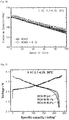
- FIG. 37 is a graph illustrating measured capacity characteristics of lithium secondary batteries including positive active materials according to Examples 1-4-1 and 1-4-2 and Comparative Example 1-4 of the present invention
- FIG. 38 is a graph illustrating measured life-span characteristics of the lithium secondary batteries including the positive active materials according to Examples 1-4-1 and 1-4-2 and Comparative Example 1-4 of the present invention.
- half cells were manufactured by using the positive active materials according to Examples 1-4-1 and 1-4-2 and Comparative Example 1-4, a discharge capacity was measured under the condition of cut off 2.7 to 4.3V, 0.1C, and a temperature of 30°C, and a capacity change according to the number of times of the charge/discharge cycle was measured under the condition of cut off 2.7 to 4.3V, 0.5C, and a temperature of 30°C.
- NCA 90 pri means the positive active material according to Comparative Examples 1-4
- NCA 90 B1% means the positive active material according to Examples 1-4-1
- NCA 90 B2% means the positive active material according to Example 1-4-2.
- [Table 8] Classification 0.1C, 1st Dis-Capa (mAh/g) 1st Efficiency 0.2CCapacity (mAh/g) 0.2C/0.1C 0.5CCapacity (mAh/g) 0.5C/0.1C 0.5C Cycle Retention Comparative Example 1-4 225.1 95.1% 220.3 97.9% 210.3 93.5% 83.7% (cycle 100)
- Example 1-4-1 222.4 94.5% 216.7 97.4% 206.1 92.7% 93.5% (cycle 100)
- Example 1-4-2 222.8 93.8% 214.3 96.2% 198.3 89.0% 94.0% (cycle 64)
- FIG. 39 is a graph illustrating measured capacity characteristics of lithium secondary batteries including positive active materials according to Example 1-6 and Comparative Example 1-6 of the present invention
- FIG. 40 is a graph illustrating measured life-span characteristics of the lithium secondary batteries including the positive active materials according to Example 1-6 and Comparative Example 1-6 of the present invention.
- half cells were manufactured by using the positive active materials according to Example 1-6 and Comparative Example 1-6, a discharge capacity was measured under the condition of cut off 2.7 to 4.3V, 0.1C, and a temperature of 30°C, and a capacity change according to the number of times of the charge/discharge cycle was measured under the condition of cut off 2.7 to 4.3V, 0.5C, and a temperature of 30°C.
- NCA 950401 Ref means the positive active material according to Comparative Example 1-6
- NCA 950401 B1% means the positive active material according to Example 1-6.
- [Table 9] Classification 0.1C, 1st Dis-Capa (mAh/g) 1st Efficiency 0.2CCapacity (mAh/g) 0.2C/0.1C 0.5CCapacity (mAh/g) 0.5C/0.1C 0.5C CycleRetention Comparative Example 1-6 236.8 95.1% 231.3 97.7% 219.4 92.7% 81.6% (cycle 100)
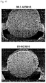
- FIG. 41 is a SEM picture of positive active material precursors and positive active materials according to Examples 2-1-1 and 2-1-2 of the present invention
- FIG. 42 is a graph illustrating measured capacity characteristics of the lithium secondary batteries including the positive active materials according to Examples 2-1-1 to 2-1-3 of the present invention
- FIG. 43 is a graph illustrating measured life-span characteristics of the lithium secondary batteries including the positive active materials according to Examples 2-1-1 to 2-1-3 of the present invention.
- half cells were manufactured by using the positive active materials according to Examples 2-1-1 to 2-1-3, a discharge capacity was measured under the condition of cut off 2.7 to 4.3V, 0.1C, and a temperature of 30°C, and a capacity change according to the number of times of the charge/discharge cycle was measured under the condition of cut off 2.7 to 4.3V, 0.5C, and a temperature of 30°C.
- B0.5-NC9010, B1-NC9010, and B1.5-NC9010 mean the positive active materials according to Examples 2-1-1 to 2-1-3, respectively.
- [Table 10] Classification 0.1C, 1st Dis-Capa (mAh/g) 1st Efficiency 0.2CCapacity (mAh/g) 0.2C/0.1C 0.5CCapacity (mAh/g) 0.5C/0.1C 0.5C CycleRetention Example 2-1-1 233.7 96.2% 228.5 97.8% 218.5 93.5% 84.7% (100cycle)
- Example 2-1-2 236.0 96.7% 230.5 97.7% 220.4 93.4% 91.2% (100cycle)
- Example 2-1-3 235.6 96.7% 232.2 98.6% 224.4 95.2% 93.5% (52cycle)
- FIG. 44 is a SEM picture of positive active material precursors and positive active materials according to Examples 2-2-1 and 2-2-2 of the present invention
- FIG. 45 is a graph illustrating measured capacity characteristics of the lithium secondary batteries including the positive active materials according to Examples 2-2-1 to 2-2-3 and Comparative Example 1-4 of the present invention
- FIG. 46 is a graph illustrating measured life-span characteristics of the lithium secondary batteries including the positive active materials according to Examples 2-2-1 to 2-2-3 and Comparative Example 1-4 of the present invention.
- half cells were manufactured by using the positive active materials according to Examples 2-2-1 to 2-2-3, a discharge capacity was measured under the condition of cut off 2.7 to 4.3V, 0.1C, and a temperature of 30°C, and a capacity change according to the number of times of the charge/discharge cycle was measured under the condition of cut off 2.7 to 4.3V, 0.5C, and a temperature of 30°C.
- NCA90 means the positive active material according to Comparative Example 1-4
- B0.5-NCA90, B1-NCA90, and B1.5-NCA90 mean the positive active materials according to Examples 2-2-1 to 2-2-3, respectively.
- [Table 11] Classification 0.1C, 1st Dis-Capa (mAh/g) 1st Efficiency 0.2CCapacity (mAh/g) 0.2C/0.1C 0.5CCapacity (mAh/g) 0.5C/0.1C 0.5C CycleRetention Comparative Example 1-4 225.1 95.1% 220.3 97.9% 210.6 93.5% 83.7% (100cycle)
- FIG. 47 is a TEM picture of a positive active material according to Example 3 of the present invention. Referring to FIG. 47 , a TEM picture of a positive active material according to Example 3 of the present invention was taken. The arrangement property of the primary particle was measured by using the TEM picture. Aa can be seen in FIG. 47 , it can be seen that when tungsten is doped, orientation of the primary particles increases, so that the primary particles are arranged in the radiation direction.
- FIG. 48 is a graph illustrating measured capacity characteristics of the lithium secondary batteries including the positive active materials according to Example 3 and Comparative Example 1-5 of the present invention
- FIG. 49 is a graph illustrating measured life-span characteristics of the lithium secondary batteries including the positive active materials according to Example 3 and Comparative Example 1-5 of the present invention.
- half cells were manufactured by using the positive active materials according to Example 3 and Comparative Example 1-5, a discharge capacity was measured under the condition of cut off 2.7 to 4.3V, 0.1C, and a temperature of 30°C, and a capacity change according to the number of times of the charge/discharge cycle was measured under the condition of cut off 2.7 to 4.3V, 0.5C, and a temperature of 30°C.
- NCM 90 means the positive active material according to Comparative Example 1-5
- W1.0-NCM 90 means the positive active material according to Example 3.
- the positive active material according to the exemplary embodiment of the present invention, the method of preparing the same, a lithium secondary battery including the same are applicable to an electric vehicle, an ESS, and a portable electronic device.
Landscapes
- Chemical & Material Sciences (AREA)
- Chemical Kinetics & Catalysis (AREA)
- Electrochemistry (AREA)
- General Chemical & Material Sciences (AREA)
- Inorganic Chemistry (AREA)
- Engineering & Computer Science (AREA)
- Organic Chemistry (AREA)
- Materials Engineering (AREA)
- Manufacturing & Machinery (AREA)
- Composite Materials (AREA)
- Battery Electrode And Active Subsutance (AREA)
Abstract
Description
- This application is a continuation of pending International Application No.
PCT/KR2019/000561 10-2018-0004416 10-2019-0004907 - The present application relates to a positive active material, a method of preparing the same, and a lithium secondary battery including the same, and more particularly, to a positive active material in which boron is doped, a method of preparing the same, and a lithium secondary battery including the same.
- With the development of portable mobile electronic devices, such as a smart phone, an MP3 player, and a tablet PC, the demand for secondary batteries capable of storing electric energy is explosively increasing.
- Particularly, with the advent of electric vehicles, medium and large energy storing systems, and portable devices requiring high energy density, the demand for lithium secondary batteries is increasing. As such, the demand for the lithium secondary batteries increases, so that research and development of positive active materials used in the lithium secondary batteries is in progress. For example, Korean Patent Application Publication No.
10-2014-0119621 10-2013-0150315 - A technical problem to be solved by the present application is to provide a high-capacity positive active material, a method of preparing the same, and a lithium secondary battery including the same.
- Another technical problem to be solved by the present application is to provide a positive active material having a long life-span, a method of preparing the same, and a lithium secondary battery including the same.
- Another technical problem to be solved by the present application is to provide a highly stable positive active material, a method of preparing the same, and a lithium secondary battery including the same.
- Another technical problem to be solved by the present application is to provide a positive active material in which a life-span shortening characteristic according to the number of times of charge/discharge is minimized, a method of preparing the same, and a lithium secondary battery including the same.
- Another technical problem to be solved by the present application is to provide a positive active material doped with boron, a method of preparing the same, and a lithium secondary battery including the same.
- Another technical problem to be solved by the present application is to provide a positive active material in which the generation of cracks according to the number of times of charge/discharge is minimized, a method of preparing the same, and a lithium secondary battery including the same.
- Another technical problem to be solved by the present application is to provide a positive active material having a high nickel concentration, a method of preparing the same, and a lithium secondary battery including the same.
- The technical problems to be solved by the present application are not limited to the foregoing.
- In order to solve the technical object, the present application provides a positive active material.
- According to an exemplary embodiment, the positive active material includes a secondary particle in which a plurality of primary particles is agglomerated, in which in the positive active material, a compound containing nickel, lithium, and oxygen is doped with at least one of boron (B), titanium (Ti), zirconium (Zr), tungsten (W), molybdenum (Mo), tin (Sn), and tantalum (Ta), and a concentration of nickel is 79 mol% or more.
- According to the exemplary embodiment, a concentration of boron may be less than 2 mol%.
- According to the exemplary embodiment, the primary particle may be extended in a direction from a center portion to a surface portion of the secondary particle, and an aspect ratio of the primary particle may increase by boron.
- According to the exemplary embodiment, the active positive material may further include at least one of aluminum, cobalt, and manganese.
- According to the exemplary embodiment, boron may be provided on a surface portion of the primary particle.
- According to the exemplary embodiment, the positive active material may be expressed by Chemical Formula 1 below, and (003) surface of the primary particle increases and (014) surface and (104) surface decrease by boron.
[Chemical Formula 1] LiaM1xM2yBzO2
- According to the exemplary embodiment, the (003) surface of the primary particle may be arranged to be parallel to a direction from a center portion to a surface portion of the secondary particle.
- According to the exemplary embodiment, as the concentration of nickel increases, a concentration of boron may decrease.
- According to the exemplary embodiment, an average angle between an extension direction of the primary particles located at the outermost portion in the secondary particle and a radiation direction from a center portion to a surface portion of the secondary particle may be 10° or less.
- In order to solve the technical problem, the present invention provides a lithium secondary battery.
- According to the exemplary embodiment, the lithium secondary battery may include: a positive electrode including the positive active material according to the exemplary embodiment of the present invention; a negative electrode spaced apart from the positive electrode; and an electrolyte between the positive electrode and the negative electrode.
- According to the exemplary embodiment, an a-axis of a crystal structure of the plurality of primary particles of the positive active material may be extended in a direction from a center portion to a surface portion of the secondary particle, in a charge/discharge process, the primary particle may be contracted and expanded in a c-axis direction, and cracks generated between the adjacent primary particles may be aligned.
- In order to solve the technical problem, the present invention provides a method of preparing a positive active material.
- According to the exemplary embodiment, the method may include: preparing a positive active material precursor including a hydroxide containing nickel of 80 mol% or more by using a nickel precursor; and preparing a positive active material in which a compound containing nickel, lithium, and oxygen is doped with boron by mixing and calcining the positive active material precursor, lithium salt, and a boron precursor.
- According to the exemplary embodiment, the method may include: preparing a positive active material precursor in which a hydroxide containing nickel of 79 mol% or more is doped with boron by using a nickel precursor and a boron precursor; and preparing a positive active material in which a compound containing nickel, lithium, and oxygen is doped with boron by mixing and calcining the positive active material precursor and lithium salt.
- According to the exemplary embodiment, the preparing of the positive active material may include adding an aluminum precursor together with the positive active material precursor and mixing and calcining the positive active material precursor, the lithium salt, and the aluminum precursor.
- The positive active material according to the exemplary embodiment of the present invention may include a secondary particle in which a plurality of primary particles is agglomerated, and in which a compound containing nickel, lithium, and oxygen is doped with boron.
- By the boron doping, the primary particle may have a high aspect ratio, and further, may have high orientation in which the primary particles are arranged in the form radiated from a center of the secondary particle. That is, an a-axis of the primary particles having the high aspect ratio may be highly consistent with the direction radiated from the center of the secondary particle. Accordingly, it is possible to minimize the generation of cracks by easily relaxing stress according to the contraction and the expansion of the primary particles in the charge/discharge process, and prevent an impurity phase by a parasitic reaction of an electrolyte from being generated even in an inner portion of the secondary particle.
- Accordingly, it is possible to provide the positive active material with the minimized life-span shortening characteristic in the high-nickel positive active material.
-
-
FIG. 1 is a flowchart for describing a method of preparing a positive active material according to an exemplary embodiment of the present invention. -
FIG. 2 is a flowchart for describing a method of preparing a positive active material according to another exemplary embodiment of the present invention. -
FIG. 3 is a diagram for describing a positive active material according to an exemplary embodiment of the present invention. -
FIG. 4 is a diagram taken along line A-B ofFIG. 3 . -
FIG. 5 is a diagram for describing a stress relaxation effect according to an alignment of primary particles of the positive active material according to the exemplary embodiment of the present invention. -
FIG. 6 is a diagram for describing a stress relaxation effect according to an alignment of primary particles of the positive active material according to a comparative example of the present invention. -
FIGS. 7A to 7C are graphs illustrating XRD results of positive active materials according to Examples 1-5-1 and 1-5-2, and Comparative Example 1-5 of the present invention. -
FIG. 8 is a Scanning Electron Microscope (SEM) picture of the positive active materials according to Comparative Example 1-5 and Examples 1-5-1 and 1-5-2 of the present invention. -
FIG. 9 is a Scanning Transmission Electron Microscope (STEM) picture of the positive active materials according to Comparative Example 1-5 and Examples 1-5-2 of the present invention. -
FIG. 10 is an enlarged TEM picture and a diagram for describing an ED pattern and a crystal structure of the positive active material according to Example 1-5-2 of the present invention. -
FIG. 11 is a graph for describing surface energy of the positive active material doped with boron according to the Examples of the present invention. -
FIGS. 12 to 15 are diagrams illustrating a structural model of the positive active material doped with boron according to the Examples of the present invention. -
FIG. 16 is a graph illustrating capacity characteristics of lithium secondary batteries including positive active materials according to Comparative Example 1-5 and Examples 1-5-1 to 1-5-3 of the present invention measured at 30°C. -
FIG. 17 is a graph illustrating life-span characteristics of lithium secondary batteries including the positive active materials according to Comparative Example 1-5 and Examples 1-5-1 to 1-5-3 of the present invention measured at 30°C. -
FIG. 18 is a graph illustrating capacity characteristics of lithium secondary batteries including the positive active materials according to Comparative Example 1-5 and Examples 1-5-1 and 1-5-2 of the present invention measured at 55°C. -
FIG. 19 is a graph illustrating life-span characteristics of the lithium secondary batteries including the positive active materials according to Comparative Example 1-5 and Examples 1-5-1 and 1-5-2 of the present invention measured at 55°C. -
FIGS. 20A and 20B are graphs illustrating differential capacities of the lithium secondary batteries including the positive active materials according to Comparative Example 1-5 and Example 1-5-2 of the present invention measured at 55°C. -
FIGS. 21A ,21B, and 21C are graphs illustrating differential capacities of the lithium secondary batteries including positive active materials according to Comparative Example 1-5 and Examples 1-5-1 and 1-5-2 of the present invention measured at 30°C. -
FIG. 22 is a SEM picture of the positive active materials according to Comparative Example 1-5 and Example 1-5-2 of the present invention. -
FIG. 23 is a graph illustrating an XRD measurement result after the positive active materials according to Comparative Example 1-5 and Example 1-5-2 of the present invention are charged. -
FIG. 24 is a graph for describing a change in an a-axis length and a c-axis length before and after the positive active materials according to Comparative Example 1-5 and Example 1-5-2 of the present invention are charged. -
FIG. 25 is a STEM picture of the positive active materials according to Comparative Example 1-5 and Examples 1-5-1 and 1-5-2 of the present invention of which charge/discharge is performed 100 times. -
FIG. 26 is a SEM picture of the positive active materials after the lithium secondary batteries including the positive active materials according to Comparative Example 1-5 and Examples 1-5-1 and 1-5-2 of the present invention, of which charge/discharge is performed 100 times, are charged/discharged 100 times. -
FIG. 27 is an enlarged TEM picture of the positive active material according to Comparative Example 1-5 of which charge/discharge is performed 100 times, and a FFT diagram for zones I and II. -
FIGS. 28A, 28B ,28C , and28D are a diagram illustrating an equivalent circuit of a Nyquist plot, and graphs illustrating a comparison of Rsf and Rct of the positive active materials according to Comparative Example 1-5 and Example 1-5-2. -
FIG. 29 is SEM pictures of positive active materials according to Comparative Example 1-1 and Example 1-1 of the present invention. -
FIG. 30 is SEM pictures of positive active materials according to Comparative Example 1-2 and Example 1-2 of the present invention. -
FIG. 31 is SEM pictures of positive active materials according to Comparative Example 1-3 and Example 1-3 of the present invention. -
FIG. 32 is TEM pictures of positive active materials according to Comparative Example 1-4 and Example 1-4-1 of the present invention. -
FIG. 33 is TEM pictures of positive active materials according to Comparative Example 1-5 and Example 1-5-2 of the present invention. -
FIG. 34 is a graph illustrating an evaluated arrangement property of the primary particle according to the content of nickel in the positive active materials according to Examples and Comparative Examples of the present invention. -
FIG. 35 is a graph illustrating measured capacity characteristics of lithium secondary batteries including positive active materials according to Example 1-3 and Comparative Example 1-3 of the present invention. -
FIG. 36 is a graph illustrating measured life-span characteristics of the lithium secondary batteries including the positive active materials according to Example 1-3 and Comparative Example 1-3 of the present invention. -
FIG. 37 is a graph illustrating measured capacity characteristics of lithium secondary batteries including positive active materials according to Examples 1-4-1 and 1-4-2 and Comparative Example 1-4 of the present invention. -
FIG. 38 is a graph illustrating measured life-span characteristics of the lithium secondary batteries including the positive active materials according to Examples 1-4-1 and 1-4-2 and Comparative Example 1-4 of the present invention. -
FIG. 39 is a graph illustrating measured capacity characteristics of lithium secondary batteries including positive active materials according to Example 1-6 and Comparative Example 1-6 of the present invention. -
FIG. 40 is a graph illustrating measured life-span characteristics of the lithium secondary batteries including the positive active materials according to Example 1-6 and Comparative Example 1-6 of the present invention. -
FIG. 41 is a SEM picture of positive active material precursors and positive active materials according to Examples 2-1-1 and 2-1-2 of the present invention. -
FIG. 42 is a graph illustrating measured capacity characteristics of the lithium secondary batteries including the positive active materials according to Examples 2-1-1 to 2-1-3 of the present invention. -
FIG. 43 is a graph illustrating measured life-span characteristics of the lithium secondary batteries including the positive active materials according to Examples 2-1-1 to 2-1-3 of the present invention. -
FIG. 44 is a SEM picture of positive active material precursors and positive active materials according to Examples 2-2-1 and 2-2-2 of the present invention. -
FIG. 45 is a graph illustrating measured capacity characteristics of the lithium secondary batteries including the positive active materials according to Examples 2-2-1 to 2-2-3 and Comparative Example 1-4 of the present invention. -
FIG. 46 is a graph illustrating measured life-span characteristics of the lithium secondary batteries including the positive active materials according to Examples 2-2-1 to 2-2-3 and Comparative Example 1-4 of the present invention. -
FIG. 47 is a TEM picture of a positive active material according to Example 3 of the present invention. -
FIG. 48 is a graph illustrating measured capacity characteristics of the lithium secondary batteries including the positive active materials according to Example 3 and Comparative Example 1-5 of the present invention. -
FIG. 49 is a graph illustrating measured life-span characteristics of the lithium secondary batteries including the positive active materials according to Example 3 and Comparative Example 1-5 of the present invention. - Hereinafter, an exemplary embodiment of the present invention will be described in detail with reference to the accompanying drawings. However, the technical spirit of the present invention is not limited to the following exemplary embodiments, but may also be implemented in other forms. Rather, the embodiments introduced herein are provided so as to make the disclosed contents be thorough and complete and to fully transfer the spirit of the present invention to those skilled in the art.
- In the present specification, when it is said that one constituent element is formed on another constituent element, the constituent element may be directly formed on another constituent element, or may be formed on the another constituent element with a third constituent element interposed therebetween. Further, in the drawings, thicknesses of layers and regions are exaggerated for the effective description of the technical contents.
- Further, in the various exemplary embodiments of the present specification, although terms, such as "a first", "a second", and "a third", are used for describing various constituent elements, but the constituent elements are not limited by the terms. The terms are simply used for discriminating one constituent element from another constituent element. Accordingly, a first constituent element mentioned in any one exemplary embodiment may also be mentioned as a second constituent element in another exemplary embodiment. Each exemplary embodiment described and exemplified herein also includes a complementary exemplary embodiment thereof. Further, in the present specification, the term "and/or" is used as a meaning including at least one among the constituent elements listed before and after.
- Singular expressions used herein include plurals expressions unless they have definitely opposite meanings in the context. It will be appreciated that terms "including" and "having" are intended to designate the existence of characteristics, numbers, steps, constituent elements, and a combination thereof described in the specification, and do not exclude a possibility of the existence or addition of one or more other characteristics, numbers, steps, constituent elements, or a combination thereof.
- Further, in the following description of the present invention, when a detailed description of a related publicly known function or configuration is determined to unnecessarily make the subject matter of the present invention unclear, the detailed description thereof will be omitted.
- Further, in the specification of the present application, a crystal system may consist of seven systems including a triclinic system, a monoclinic system, an orthorhombic system, a tetragonal system, a trigonal or rhombohedral system, a hexagonal system, and a cubic system.
- Further, in the specification of the present application, "mol%" is interpreted to mean the content of predetermined element included in a positive active material or a positive active material precursor when it is assumed that the sum of remaining elements excluding lithium, oxygen, and hydrogen in the positive active material or the positive active material precursor is 100%.
-
FIG. 1 is a flowchart for describing a method of preparing a positive active material according to an exemplary embodiment of the present invention,FIG. 2 is a flowchart for describing a method of preparing a positive active material according to another exemplary embodiment of the present invention,FIG. 3 is a diagram for describing a positive active material according to an exemplary embodiment of the present invention,FIG. 4 is a diagram taken along line A-B ofFIG. 3 ,FIG. 5 is a diagram for describing a stress relaxation effect according to an alignment of primary particles of the positive active material according to the exemplary embodiment of the present invention, andFIG. 6 is a diagram for describing a stress relaxation effect according to an alignment of primary particles of the positive active material according to a comparative example of the present invention. - Referring to
FIGS. 1 to 6 , a positiveactive material 100 according to an exemplary embodiment of the present invention may include a material in which a compound containing nickel, lithium, and oxygen is doped with boron. For example, the positiveactive material 100 may be the material in which a compound of lithium, nickel, and oxygen is doped with boron, the material in which a compound of lithium, nickel, cobalt, and oxygen is doped with boron, the material in which a compound of lithium, nickel, cobalt, manganese, and oxygen is doped with boron, and the material in which a compound of lithium, nickel, cobalt, aluminum, and oxygen is doped with boron. - According to the exemplary embodiment, a concentration of boron in the positive
active material 100 may be less than 2 mol%. Accordingly, a charge/discharge characteristic and a life-span characteristic of a lithium secondary battery including the positiveactive material 100 may be improved. In contrast, when the concentration of boron is 2 mol% or more, a charge/discharge characteristic and a life-span characteristic of a lithium secondary battery may deteriorate. - According to the exemplary embodiment, as a concentration of nickel in the positive
active material 100 increases, the concentration of boron may decrease. That is, according to the concentration of nickel in the positiveactive material 100, the concentration of doped boron may be controlled. - According to the exemplary embodiment, a concentration of at least one of nickel, cobalt, manganese, and aluminum may be substantially constant in the positive
active material 100. Otherwise, according to another exemplary embodiment, a concentration of at least one of nickel, cobalt, manganese, and aluminum in the positiveactive material 100 may have, in a direction from a center of a particle to a surface of the particle, a concentration gradient in the entire particle or a concentration gradient in a part of the particle. Otherwise, according to another exemplary embodiment, the positiveactive material 100 may include a core portion and a shell portion having a different concentration of metal (at least one of nickel, cobalt, manganese, and aluminum) from that of the core portion. The technical spirit according to the exemplary embodiment of the present invention may be applied to the positive active materials having various structures and forms. - According to the exemplary embodiment, the positive
active material 100 may be represented byChemical Formula 1 below.
<Chemical Formula 1> LiaM1xM2yBzO2
- In
Chemical Formula - The positive active material may include
primary particles 30 and a secondary particle in which theprimary particles 30 are agglomerated. As described above, when boron is doped, boron may be mainly provided on a surface portion of theprimary particle 30. - The
primary particles 30 may be extended in a direction in which theprimary particles 30 are radiated from one region of an inner portion of the secondary particle to asurface portion 20 of the secondary particle. The one region of the inner portion of the secondary particle may be acenter portion 10 of the secondary particle. That is, theprimary particle 30 may have a rod shape extended from the one region of the inner portion of the secondary particle to thesurface portion 20 of the secondary particle. - According to the exemplary embodiment, the
primary particle 30 relatively adjacent to thesurface portion 20 of the secondary particle may have a longer length in a direction from thecenter portion 10 of the inner portion of the secondary particle to thesurface portion 20 of the secondary particle than theprimary particle 30 relatively adjacent to the center portion of theinner portion 10 of the secondary particle. That is, in at least a part of the secondary particle extended from thecenter portion 10 to thesurface portion 20 of the secondary particle, the lengths of theprimary particles 30 may increase as theprimary particles 30 are adjacent to thesurface portion 20 of the secondary particle. - The lengths of the
primary particles 30 may increase by the doped boron. The lengths of theprimary particles 30 may be in the direction from thecenter portion 10 of the secondary particle to thesurface portion 20. That is, an aspect ratio corresponding to a ratio of a length value of theprimary particle 30 to a width of theprimary particle 30 may increase. Accordingly, lithium ions may be easily provided into the secondary particle. - Further, by the boron doping, (003) surface of the
primary particle 30 may increase and (014) surface and (104) surface may decrease, and (003) surface of theprimary particle 30 may be arranged to be parallel to the direction from thecenter portion 10 to thesurface portion 20 of the secondary particle. That is, an a-axis of a crystal structure of theprimary particle 30 may be arranged to be parallel to the direction from thecenter portion 10 to thesurface portion 20 of the secondary particle, and as described above, (003) surface of theprimary particle 30 increases by the boron doping, so that the aspect ratio of theprimary particle 30 may increase and an orientation property of theprimary particle 30 may increase. For example, an average angle of an extension direction of theprimary particles 30 located at the outermost portion of the secondary particle and the radiation direction from the center portion to the surface portion of the secondary particle may be 10° or less. - Accordingly, a movement path of metal ions (for example, lithium ions) and an electrolyte may be provided between the spaces between the
primary particles 30 having the rod shapes, that is, the spaces between theprimary particles 30 extended in a direction D from thecenter portion 10 to thesurface portion 20 of the secondary particle. Accordingly, charge/discharge efficiency of a secondary battery including the positive active material according to the exemplary embodiment of the present invention may be improved. - According to insertion and de-intercalation of the lithium ions in the charge/discharge process of the lithium secondary battery including the positive active material, the primary particle may be contracted and expanded in a c-axis. According to the contraction and the expansion of the primary particle in the c-axis, a crack may be generated in the inner portion of the positive active material and the electrolyte may flow into the crack. By a parasitic reaction of the electrolyte flowing through the crack, a NiO-like impurity phase may be formed.
- As described in
FIG. 5 , according to the exemplary embodiment of the present invention, by the boron doping, the primary particle may have a high aspect ratio and have orientation in which the primary particles are arranged in the form radiated from the center of the secondary particle. That is, the a-axis of the primary particles having the high aspect ratio may be highly consistent with the direction radiated from the center of the secondary particle. Accordingly, even though the primary particles are contracted and expanded in the c-axis direction in the charge/discharge process, the arranged primary particles easily relax stress, thereby minimizing the generation of the crack and preventing the Ni-O likeimpurity phase 110 by the parasitic reaction of the electrolyte from being generated up to the inner portion of the secondary particle. - In the meantime, unlike the exemplary embodiment of the present invention, when boron is not doped, as illustrated in
FIG. 6 , the primary particle may have a low aspect ratio and further may have lower orientation radiated from the center of the secondary particle. That is, the a-axis of the primary particles having the low aspect ratio may be little consistent with the direction radiated from the center of the secondary particle (randomly displaced). Accordingly, the crack may be easily generated in the inner portion of the secondary particle by stress generated in the contraction and expansion process of the primary particles in the c-axis direction in the charge/discharge process, and accordingly, the Ni-O likeimpurity phase 110 by the parasitic reaction of the electrolyte is generated up to the inner portion of the secondary particle, thereby degrading a charge/discharge characteristic and a life-span characteristic. - However, as described above, according to the exemplary embodiment of the present invention, the a-axis of the primary particles having the high aspect ratio is highly consistent with the direction radiated from the center of the secondary particle, so that the generation of the crack may be minimized during the charge/discharge process, thereby providing the positive active material with the improved charge/discharge capacity and life-span characteristic.
- Subsequently, the method of preparing the positive active material according to the exemplary embodiment of the present invention will be described with reference to
FIGS. 1 and2 . - Referring to
FIG. 1 , a positive active material precursor including a hydroxide including nickel of 80 mol% or more is prepared by using a nickel precursor (S110). The nickel precursor may be nickel sulfate. When the positive active material precursor includes cobalt, a cobalt precursor (for example, cobalt surface) may be further used, and when the positive active material precursor includes manganese, a manganese precursor (for example, manganese surface) may be further used. - For example, the positive active material precursor may be expressed by
Chemical Formula 2 below.
<Chemical Formula 2> [M1xM2y](OH)2
- In
Chemical formula 2, 0.80≤x≤1.00, 0≤y≤0.2, M1 is nickel, and M2 may include at least one of cobalt and manganese. - A positive active material, in which a compound containing nickel, lithium, and oxygen is doped with boron, may be prepared by mixing and calcining the positive active material precursor, lithium salt, and a boron precursor (S120). For example, the boron precursor may be a boron oxide (B2O3).
- When the positive active material further includes aluminum, the operation of preparing of the positive active material may include mixing and calcining the positive active material precursor, lithium salt, a boron precursor, and an aluminum precursor.
- A method of preparing a positive active material according to another exemplary embodiment of the present invention will be described.
- Referring to
FIG. 2 , a positive active material precursor, in which a hydroxide including nickel of 79 mol% or more is doped with boron, may be prepared by using a nickel precursor and a boron precursor (S210). As described above, the nickel precursor may be nickel surface, and when the positive active material precursor includes cobalt, a cobalt precursor (for example, cobalt surface) may be further used, and when the positive active material precursor includes manganese, a manganese precursor (for example, manganese surface) may be further used. For example, the boron precursor may be a boron oxide (B2O3). - For example, the positive active material precursor may be expressed by
Chemical Formula 3 below.
<Chemical Formula 3> [M1xM2yBz](OH)2
- In
Chemical Formula 3, 0.79≤x<1, 0≤y≤0.2, and 0<z<0.02, and M1 is nickel, and M2 may include at least one of aluminum, cobalt, and manganese. - A positive active material, in which a compound containing nickel, lithium, and oxygen is doped with boron, may be prepared by mixing and calcining the positive active material precursor and lithium salt (S220).
- As described above, when the positive active material further includes aluminum, the preparing of the positive active material may include mixing and calcining the positive active material precursor, lithium salt, and an aluminum precursor.
- Hereinafter, the particular method of preparing the positive active material according to the exemplary embodiment of the present invention and a characteristic evaluation result will be described.
- Distilled water was added to a co-precipitation reactor and then stirred while N2 gas was supplied to the reactor. A metal aqueous solution, in which a molar ratio of nickel sulfate, cobalt sulfate, and manganese sulfate is 60:20:20, and an ammonia aqueous solution were continuously added to the reactor. Further, a sodium hydroxide solution was simultaneously supplied for pH adjustment to prepare a [Ni0.60Co0.20Mn0.20](OH)2 metal composite hydroxide.
- The prepared [Ni0.60Co0.20Mn0.20](OH)2 metal composite hydroxide was washed with water, filtered, and then dried at a vacuum drier at 110°C. The metal composite hydroxide and a lithium hydroxide (LiOH) were mixed at a molar ratio of 1:1.01 and then calcined at 850°C in an oxygen atmosphere to prepare Li[Ni0.60Co0.20Mn0.20]O2 positive active material powder.
- Distilled water was added to a co-precipitation reactor and then stirred while N2 gas was supplied to the reactor. A metal aqueous solution, in which a molar ratio of nickel sulfate, cobalt sulfate, and manganese sulfate is 60:20:20, and an ammonia aqueous solution were continuously added to the reactor. Further, a sodium hydroxide solution was simultaneously supplied for pH adjustment to prepare a [Ni0.60Co0.20Mn0.20](OH)2 metal composite hydroxide.
- The prepared [Ni0.60Co0.20Mn0.20](OH)2 metal composite hydroxide was washed with water, filtered, and then dried at a vacuum drier at 110°C. The metal composite hydroxide, a boron oxide (B2O3), and a lithium hydroxide (LiOH) were mixed at a molar ratio of 0.99:0.005:1.01 and then calcined at 850°C in an oxygen atmosphere to prepare Li[Ni0.59Co0.20Mn0.20B0.01]O2 positive active material powder.
- Distilled water was added to a co-precipitation reactor and then stirred while N2 gas was supplied to the reactor. A metal aqueous solution, in which a molar ratio of nickel sulfate, cobalt sulfate, and manganese sulfate is 70:15:15, and an ammonia aqueous solution were continuously added to the reactor. Further, a sodium hydroxide solution was simultaneously supplied for pH adjustment to prepare a [Ni0.70Co0.15Mn0.15](OH)2 metal composite hydroxide.
- The prepared [Ni0.70Co0.15Mn0.15](OH)2 metal composite hydroxide was washed with water, filtered, and then dried at a vacuum drier at 110°C. The metal composite hydroxide and a lithium hydroxide (LiOH) were mixed at a molar ratio of 1:1.01 and then calcined at 800 °C in an oxygen atmosphere to prepare Li[Ni0.70Co0.15Mn0.15]O2 positive active material powder.
- Distilled water was added to a co-precipitation reactor and then stirred while N2 gas was supplied to the reactor. A metal aqueous solution, in which a molar ratio of nickel sulfate, cobalt sulfate, and manganese sulfate is 70:15:15, and an ammonia aqueous solution were continuously added to the reactor. Further, a sodium hydroxide solution was simultaneously supplied for pH adjustment to prepare a [Ni0.70Co0.15Mn0.15](OH)2 metal composite hydroxide.
- The prepared [Ni0.70Co0.15Mn0.15](OH)2 metal composite hydroxide was washed with water, filtered, and then dried at a vacuum drier at 110°C. The metal composite hydroxide, a boron oxide (B2O3), and a lithium hydroxide (LiOH) were mixed at a molar ratio of 0.99:0.005:1.01 and then calcined at 800 °C in an oxygen atmosphere to prepare Li[Ni0.69Co0.15Mn0.15B0.01]O2 positive active material powder.
- Distilled water was added to a co-precipitation reactor and then stirred while N2 gas was supplied to the reactor. A metal aqueous solution, in which a molar ratio of nickel sulfate and cobalt sulfate is 83:17, and an ammonia aqueous solution were continuously added to the reactor. Further, a sodium hydroxide solution was supplied for pH adjustment to prepare a [Ni0.83Co0.17](OH)2 metal composite hydroxide.
- The prepared [Ni0.83Co0.17](OH)2 metal composite hydroxide was washed with water, filtered, and then dried at a vacuum drier at 110°C. The metal composite hydroxide, an aluminum hydroxide (Al(OH)3), and a lithium hydroxide (LiOH) were mixed at a molar ratio of 0.96:0.04:1.01 and then calcined at 750°C in an oxygen atmosphere to prepare Li[Ni0.80Co0.16Al0.04]O2 positive active material powder.
- Distilled water was added to a co-precipitation reactor and then stirred while N2 gas was supplied to the reactor. A metal aqueous solution, in which a molar ratio of nickel sulfate and cobalt sulfate is 83:17, and an ammonia aqueous solution were continuously added to the reactor. Further, a sodium hydroxide solution was supplied for pH adjustment to prepare a [Ni0.83Co0.17](OH)2 metal composite hydroxide.
- The prepared [Ni0.83Co0.17](OH)2 metal composite hydroxide was washed with water, filtered, and then dried at a vacuum drier at 110°C. The metal composite hydroxide, a boron oxide (B2O3), an aluminum oxide (Al(OH)3), and a lithium hydroxide (LiOH) were mixed at a molar ratio of 0.95:0.005:0.04:1.01 and then calcined at 750°C in an oxygen atmosphere to prepare Li[Ni0.79Co0.16Al0.04B0.01]O2 positive active material powder.
- Distilled water was added to a co-precipitation reactor and then stirred while N2 gas was supplied to the reactor. A metal aqueous solution, in which a molar ratio of nickel sulfate and cobalt sulfate is 90:10, and an ammonia aqueous solution were continuously added to the reactor. Further, a sodium hydroxide solution was supplied for pH adjustment to prepare a [Ni0.90Co0.10](OH)2 metal composite hydroxide.
- The prepared [Ni0.90Co0.10](OH)2 metal composite hydroxide was washed with water, filtered, and then dried at a vacuum drier at 110°C. The metal composite hydroxide, an aluminum hydroxide (Al(OH)3), and a lithium hydroxide (LiOH) were mixed at a molar ratio of 0.985:0.015:1.01 and then calcined at 730°C in an oxygen atmosphere to prepare Li[Ni0.885Co0.10Al0.015]O2 positive active material powder.
- Distilled water was added to a co-precipitation reactor and then stirred while N2 gas was supplied to the reactor. A metal aqueous solution, in which a molar ratio of nickel sulfate and cobalt sulfate is 90:10, and an ammonia aqueous solution were continuously added to the reactor. Further, a sodium hydroxide solution was supplied for pH adjustment to prepare a [Ni0.90Co0.10](OH)2 metal composite hydroxide.
- The prepared [Ni0.90Co0.10](OH)2 metal composite hydroxide was washed with water, filtered, and then dried at a vacuum drier at 110°C. The metal composite hydroxide, a boron oxide (B2O3), an aluminum oxide (Al(OH)3), and a lithium hydroxide (LiOH) were mixed at a molar ratio of 0.975:0.005:0.015:1.01 and then calcined at 730°C in an oxygen atmosphere to prepare Li[Ni0.875Co0.10Al0.015B0.01]O2 positive active material powder.
- Distilled water was added to a co-precipitation reactor and then stirred while N2 gas was supplied to the reactor. A metal aqueous solution, in which a molar ratio of nickel sulfate and cobalt sulfate is 90:10, and an ammonia aqueous solution were continuously added to the reactor. Further, a sodium hydroxide solution was supplied for pH adjustment to prepare a [Ni0.90Co0.10](OH)2 metal composite hydroxide.
- The prepared [Ni0.90Co0.10](OH)2 metal composite hydroxide was washed with water, filtered, and then dried at a vacuum drier at 110°C. The metal composite hydroxide, a boron oxide (B2O3), an aluminum oxide (Al(OH)3), and a lithium hydroxide (LiOH) were mixed at a molar ratio of 0.965:0.01:0.015:1.01 and then calcined at 730°C in an oxygen atmosphere to prepare Li[Ni0.865Co0.10Al0.015B0.02]O2 positive active material powder.
- Distilled water was added to a co-precipitation reactor and then stirred while N2 gas was supplied to the reactor. A metal aqueous solution, in which a molar ratio of nickel sulfate, cobalt sulfate, and manganese sulfate is 90:5:5, and an ammonia aqueous solution were continuously added to the reactor. Further, a sodium hydroxide solution was simultaneously supplied for pH adjustment to prepare a [Ni0.90Co0.05Mn0.05](OH)2 metal composite hydroxide.
- The prepared [Ni0.90Co0.05Mn0.05](OH)2 metal composite hydroxide was washed with water, filtered, and then dried at a vacuum drier at 110°C. The metal composite hydroxide and a lithium hydroxide (LiOH) were mixed at a molar ratio of 1:1.01 and then calcined at 750°C in an oxygen atmosphere to prepare Li[Ni0.90Co0.05Mn0.05]O2 positive active material powder.
- Distilled water was added to a co-precipitation reactor and then stirred while N2 gas was supplied to the reactor. A metal aqueous solution, in which a molar ratio of nickel sulfate, cobalt sulfate, and manganese sulfate is 90:5:5, and an ammonia aqueous solution were continuously added to the reactor. Further, a sodium hydroxide solution was supplied for pH adjustment to prepare a [Ni0.90Co0.05Mn0.05](OH)2 metal composite hydroxide.
- The prepared [Ni0.90Co0.05Mn0.05](OH)2 metal composite hydroxide was washed with water, filtered, and then dried at a vacuum drier at 110°C. The metal composite hydroxide, a boron oxide (B2O3), and a lithium hydroxide (LiOH) were mixed at a molar ratio of 0.996:0.002:1.01 and then calcined at 750°C in an oxygen atmosphere to prepare Li[Ni0.896Co0.05Mn0.05B0.004]O2 positive active material powder.
- Distilled water was added to a co-precipitation reactor and then stirred while N2 gas was supplied to the reactor. A metal aqueous solution, in which a molar ratio of nickel sulfate, cobalt sulfate, and manganese sulfate is 90:5:5, and an ammonia aqueous solution were continuously added to the reactor. Further, a sodium hydroxide solution was supplied for pH adjustment to prepare a [Ni0.90Co0.05Mn0.05](OH)2 metal composite hydroxide.
- The prepared [Ni0.90Co0.05Mn0.05](OH)2 metal composite hydroxide was washed with water, filtered, and then dried at a vacuum drier at 110°C. The metal composite hydroxide, a boron oxide (B2O3), and a lithium hydroxide (LiOH) were mixed at a molar ratio of 0.99:0.005:1.01 and then calcined at 750°C in an oxygen atmosphere to prepare Li[Ni0.89Co0.05Mn0.05B0.01]O2 positive active material powder.
- Distilled water was added to a co-precipitation reactor and then stirred while N2 gas was supplied to the reactor. A metal aqueous solution, in which a molar ratio of nickel sulfate, cobalt sulfate, and manganese sulfate is 90:5:5, and an ammonia aqueous solution were continuously added to the reactor. Further, a sodium hydroxide solution was supplied for pH adjustment to prepare a [Ni0.90Co0.05Mn0.05](OH)2 metal composite hydroxide.
- The prepared [Ni0.90Co0.05Mn0.05](OH)2 metal composite hydroxide was washed with water, filtered, and then dried at a vacuum drier at 110°C. The metal composite hydroxide, a boron oxide (B2O3), and a lithium hydroxide (LiOH) were mixed at a molar ratio of 0.98:0.01:1.01 and then calcined at 750°C in an oxygen atmosphere to prepare Li[Ni0.88Co0.05Mn0.05B0.02]O2 positive active material powder.
- Distilled water was added to a co-precipitation reactor and then stirred while N2 gas was supplied to the reactor. A metal aqueous solution, in which a molar ratio of nickel sulfate and cobalt sulfate is 96:4, and an ammonia aqueous solution were continuously added to the reactor. Further, a sodium hydroxide solution was simultaneously supplied for pH adjustment to prepare a [Ni0.96Co0.04](OH)2 metal composite hydroxide.
- The prepared [Ni0.96Co0.04](OH)2 metal composite hydroxide was washed with water, filtered, and then dried at a vacuum drier at 110°C. The metal composite hydroxide, an aluminum hydroxide (Al(OH)3), and a lithium hydroxide (LiOH) were mixed at a molar ratio of 0.99:0.01:1.01 and then calcined at 730°C in an oxygen atmosphere to prepare Li[Ni0.95Co0.04Al0.01]O2 positive active material powder.
- Distilled water was added to a co-precipitation reactor and then stirred while N2 gas was supplied to the reactor. A metal aqueous solution, in which a molar ratio of nickel sulfate and cobalt sulfate is 96:4, and an ammonia aqueous solution were continuously added to the reactor. Further, a sodium hydroxide solution was supplied for pH adjustment to prepare a [Ni0.96Co0.04](OH)2 metal composite hydroxide.
- The prepared [Ni0.96Co0.04](OH)2 metal composite hydroxide was washed with water, filtered, and then dried at a vacuum drier at 110°C. The metal composite hydroxide, a boron oxide (B2O3), an aluminum oxide (Al(OH)3), and a lithium hydroxide (LiOH) were mixed at a molar ratio of 0.98:0.005:0.01:1.01 and then calcined at 730°C in an oxygen atmosphere to obtain Li[Ni0.94Co0.04Al0.01B0.01]O2 positive active material powder.
- Distilled water was added to a co-precipitation reactor and then stirred while N2 gas was supplied to the reactor. A metal aqueous solution, in which a molar ratio of nickel sulfate and cobalt sulfate is 90:10, and an ammonia aqueous solution were continuously added to the reactor. Further, a sodium hydroxide solution, in which a boron oxide (B2O3) was dissolved by 0.01 M, was simultaneously supplied for pH adjustment and the boron doping to prepare a [Ni0.895Co0.10B0.005](OH)2 metal composite hydroxide.
- The prepared [Ni0.895Co0.10B0.005](OH)2 metal composite hydroxide was washed with water, filtered, and then dried at a vacuum drier at 110°C. The metal composite hydroxide and a lithium hydroxide (LiOH) were mixed at a molar ratio of 1:1.01 and then calcined at 730°C in an oxygen atmosphere to prepare Li[Ni0.895Co0.10B0.005]O2 positive active material powder.
- Distilled water was added to a co-precipitation reactor and then stirred while N2 gas was supplied to the reactor. A metal aqueous solution, in which a molar ratio of nickel sulfate and cobalt sulfate is 90:10, and an ammonia aqueous solution were continuously added to the reactor. Further, a sodium hydroxide solution, in which a boron oxide (B2O3) was dissolved by 0.02 M, was simultaneously supplied for pH adjustment and the boron doping to prepare a [Ni0.89Co010B0.01](OH)2 metal composite hydroxide.
- The prepared [Ni0.89Co0.10B0.01](OH)2 metal composite hydroxide was washed with water, filtered, and then dried at a vacuum drier at 110°C. The metal composite hydroxide and a lithium hydroxide (LiOH) were mixed at a molar ratio of 1:1.01 and then calcined at 730°C in an oxygen atmosphere to prepare Li[Ni0.89Co0.10B0.01]O2 positive active material powder.
- Distilled water was added to a co-precipitation reactor and then stirred while N2 gas was supplied to the reactor. A metal aqueous solution, in which a molar ratio of nickel sulfate and cobalt sulfate is 90:10, and an ammonia aqueous solution were continuously added to the reactor. Further, a sodium hydroxide solution, in which a boron oxide (B2O3) was dissolved by 0.04 M, was simultaneously supplied for pH adjustment and the boron doping to prepare a [Ni0.88Co0.10B0.02](OH)2 metal composite hydroxide.
- The prepared [Ni0.88Co0.10B0.02](OH)2 metal composite hydroxide was washed with water, filtered, and then dried at a vacuum drier at 110°C. The metal composite hydroxide and a lithium hydroxide (LiOH) were mixed at a molar ratio of 1:1.01 and then calcined at 730°C in an oxygen atmosphere to prepare Li[Ni0.88Co0.10B0.02]O2 positive active material powder.
- Distilled water was added to a co-precipitation reactor and then stirred while N2 gas was supplied to the reactor. A metal aqueous solution, in which a molar ratio of nickel sulfate and cobalt sulfate is 90:10, and an ammonia aqueous solution were continuously added to the reactor. Further, a sodium hydroxide solution, in which a boron oxide (B2O3) was dissolved by 0.01 M, was simultaneously supplied for pH adjustment and the boron doping to prepare a [Ni0.895Co0.10B0.005](OH)2 metal composite hydroxide.
- The prepared [Ni0.895Co0.10B0.005](OH)2 metal composite hydroxide was washed with water, filtered, and then dried at a vacuum drier at 110°C. The metal composite hydroxide, an aluminum hydroxide (Al(OH)3), and a lithium hydroxide (LiOH) were mixed at a molar ratio of 0.985:0.015:1.01 and then calcined at 730°C in an oxygen atmosphere to prepare Li[Ni0.88Co0.10Al0.015B0.005]O2 positive active material powder.
- Distilled water was added to a co-precipitation reactor and then stirred while N2 gas was supplied to the reactor. A metal aqueous solution, in which a molar ratio of nickel sulfate and cobalt sulfate is 90:10, and an ammonia aqueous solution were continuously added to the reactor. Further, a sodium hydroxide solution, in which a boron oxide (B2O3) was dissolved by 0.02 M, was simultaneously supplied for pH adjustment and the boron doping to prepare a [Ni0.89Co010B0.01](OH)2 metal composite hydroxide.
- The prepared [Ni0.89Co010B0.01](OH)2 metal composite hydroxide was washed with water, filtered, and then dried at a vacuum drier at 110°C. The metal composite hydroxide, an aluminum hydroxide (Al(OH)3), and a lithium hydroxide (LiOH) were mixed at a molar ratio of 0.985:0.015:1.01 and then calcined at 730°C in an oxygen atmosphere to prepare Li[Ni0.875Co0.10Al0.015B0.01]O2 positive active material powder.
- Distilled water was added to a co-precipitation reactor and then stirred while N2 gas was supplied to the reactor. A metal aqueous solution, in which a molar ratio of nickel sulfate and cobalt sulfate is 90:10, and an ammonia aqueous solution were continuously added to the reactor. Further, a sodium hydroxide solution, in which a boron oxide (B2O3) was dissolved by 0.04 M, was simultaneously supplied for pH adjustment and the boron doping to prepare a [Ni0.88Co0.10B0.02](OH)2 metal composite hydroxide.
- The prepared [Ni0.88Co0.10B0.02](OH)2 metal composite hydroxide was washed with water, filtered, and then dried at a vacuum drier at 110°C. The metal composite hydroxide, an aluminum hydroxide (Al(OH)3), and a lithium hydroxide (LiOH) were mixed at a molar ratio of 0.985:0.015:1.01 and then calcined at 730°C in an oxygen atmosphere to prepare Li[Ni0.865Co0.10Al0.015B0.02]O2 positive active material powder.
- WO3 powder was dissolved in a lithium hydroxide solution at a concentration of 0.47 M. A basic aqueous solution, in which W was dissolved, was prepared by dissolving the prepared solution in a sodium hydroxide solution. Distilled water was added to a co-precipitation reactor and then stirred while N2 gas was supplied to the reactor. A metal aqueous solution, in which a molar ratio of nickel sulfate, cobalt sulfate, and manganese sulfate is 90:5:5, and an ammonia solution were continuously added to the reactor. Further, the basic aqueous solution, in which W was dissolved, was supplied for pH adjustment and the addition of tungsten to prepare a [Ni0.89Co0.05Mn0.05W0.01](OH)2 metal composite hydroxide.
- The prepared [Ni0.89Co0.05Mn0.05W0.01](OH)2 metal composite hydroxide was washed with water, filtered, and then dried at a vacuum drier at 110°C for 12 hours. The metal composite hydroxide and a lithium hydroxide (LiOH) were mixed at a molar ratio of 1:1.01 and then calcined at 770°C in an oxygen atmosphere to obtain Li[Ni0.89Co0.05Mn0.05W0.01]O2 positive active material powder.
- The compositions (mol%) of the positive active materials according to the Examples and the Comparative Examples of the present invention are represented in the table below.
[Table 1] Ni Co Mn Al B Comparative Example 1-1 60 20 20 - - Example 1-1 59 20 20 - 1 Comparative Example 1-2 70 15 15 - - Example 1-2 69 15 15 - 1 Comparative Example 1-3 80 16 - 4 - Example 1-3 79 16 - 4 1 Comparative Example 1-4 88 10 - 2 - Example 1-4-1 87 10 - 2 1 Example 1-4-2 86 10 - 2 2 Comparative Example 1-5 90 5 5 - - Example 1-5-1 89.6 5 5 - 0.4 Example 1-5-2 89 5 5 - 1 Example 1-5-3 88 5 5 - 2 Comparative Example 1-6 95 4 - 1 - Example 1-6 94 4 - 1 1 [Table 2] Ni Co Mn Al B Example 2-1-1 89.5 10 - - 0.5 Example 2-1-2 89 10 - - 1 Example 2-1-3 88 10 - - 2 Example 2-2-1 88 10 - 1.5 0.5 Example 2-2-2 87.5 10 - 1.5 1 Example 2-2-3 86.5 10 - 1.5 2 [Table 3] Ni Co Mn w Comparative Example 1-5 90 5 5 - Example 3 89 5 5 1 -
FIG. 7 is a graph illustrating XRD results of positive active materials according to Examples 1-5-1 and 1-5-2, and Comparative Example 1-5 of the present invention. Referring toFIG. 7A to 7C , XRD results of positive active materials according to Comparative Example 1-5, Examples 1-5-1 and 1-5-2 of the present invention were measured.FIGS. 7A to 7C are the graphs illustrating XRD results of the positive active materials according to Comparative Example 1-5 and Examples 1-5-1 and 1-5-2 of the present invention, respectively. - As can be seen in
FIG. 7 , in the positive active material according to Comparative Example 1-5, a clear peak separation is observed in (006)/(002) and (108)/(110) reflection, so that the positive active material according to Comparative Example 1-5 has high crystallinity and a rhombohedral crystal structure corresponding to a space group of

- Lattice constants and unit cell volumes of the positive active material according to Comparative Example 1-5 and the positive active material according to Examples 1-5-1 and 1-5-2 are represented in Table 4 below. It can be seen that even though an ion radius of boron is small, a lattice constant increases according to an increase in the amount of boron doped. Further, it can be seen that a volume of a unit cell gradually increases according to a doping concentration of boron.
[Table 4] a-axis (Å) c-axis (Å) Volume (Å) Comparative Example 1-5 2.8740 14.1997 101.577 Example 1-5-1 2.8751 14.2020 101.672 Example 1-5-2 2.8764 14.2049 101.779 -
FIG. 8 is a Scanning Electron Microscope (SEM) picture of the positive active materials according to Comparative Example 1-5 and Examples 1-5-1 and 1-5-2 of the present invention,FIG. 9 is a Scanning Transmission Electron Microscope (STEM) picture of the positive active materials according to Comparative Example 1-5 and Examples 1-5-2 of the present invention, andFIG. 10 is an enlarged TEM picture and a diagram for describing an ED pattern and a crystal structure of the positive active material according to Example 1-5-2 of the present invention. Referring toFIGS. 8 to 10 , (a) to (c) ofFIG. 8 are SEM pictures of the positive active material according to Comparative Example 1-5 and Examples 1-5-1 and 1-5-2, respectively, and (d) and (e) ofFIG. 9 are STEM pictures of the positive active material according to Comparative Example 1-5 and Example 1-5-2, respectively. - As can be seen in
FIG. 9 , it can be seen that the positive active material has the form of the secondary particle in which the plurality of primary particles having the rod shape is agglomerated, and an aspect ratio and arrangement of the primary particles are improved according to the boron doping. An aspect ratio of the primary particle of the positive active material according to Comparative Example 1-5 was 2.0 and an average length was 0.55 µm, an aspect ratio of the primary particle of the positive active material according to Example 1-5-1 was 4.1 and an average length was 1.0 µm, and an aspect ratio of the primary particle of the positive active material according to Example 1-5-2 was 9.0 and an average length was 1.1 µm, which were calculated through the TEM pictures. That is, it can be seen that the aspect ratio and the average length of the primary particle considerably increase according to the doping of boron.[Table 5] Aspect ratio Average length (µm) Comparative Example 1-5 2.0 0.55 Example 1-5-1 4.1 1.0 Example 1-5-2 9.0 1.1 - Referring to
FIG. 10 , it can be seen that the a-axis of the primary particle is substantially parallel to the radius direction of the secondary particle, and each of the surfaces of the layers including Li ions of the primary particles heads the center of the secondary particle. An electron diffraction of the primary particles around the secondary particle indexed with 100 region of
FIG. 10 , the Li plane may be substantially parallel to the direction from the center to the surface of the particle.FIG. 11 is a graph for describing surface energy of the positive active material doped with boron according to Examples of the present invention, andFIGS. 12 to 15 are diagrams illustrating a structural model of the positive active material doped with boron according to the Examples of the present invention. - Referring to
FIGS. 11 to 15 , a crystallographic structure observed in the positive active material doped with boron may be derived according to surface energy reforming of the primary particle and a change in a shape of the primary particle according to the surface energy reforming. That is, crystal morphology may be generally determined by a relative size of surface energy. For example, a spherical crystal structure is formed by isotropic surface energy, a surface having high energy is mainly removed during crystal growth by anisotropic surface energy, and a final crystal shape may be determined by relative orientation of a surface of the remaining low energy. - In the LiCo2 and LiNiO2 crystals, (003) and (104) surfaces may have lowest surface energy, and for example, a flat hexagonal plate (especially, in an oxidizing environment) prefers (003) surface and the (003) surface may be dominantly formed. In the meantime, according to an increase in the contribution of the (104) surface, the crystal structure may be changed from the flat plate to a cube shape. According to the exemplary embodiment of the present invention, the primary particle of the positive active material in which boron is not doped mainly includes the (104) surface as the surface, but the primary particle of the positive active material in which boron is doped may include the (003) surface having a relative large area.
- DFT was used for calculating energy of the (003) and (104) surfaces in LiNiO2 and boron-doped LiNiO2, and the amount of Ni in the positive active material including Ni of 90 mol% is similar to the amount of Ni in LiNiO2, and even though Ni is substituted with Mn by 10%, the surface energy of the (003) surface is not substantially changed, so that LiNiO2 was used as a model structure for simplifying the calculation.
- Further, in addition to the stoichiometric (003) side, the Li-poor and Li-rich surfaces in the LiNiO2 particle were found to exists on the surface, so that a non-stoichiometric (003) surface was also considered.
- According to the DFT calculation, it is represented that an Ni site is a position advantageous to boron doping (
FIG. 15 ), which is because B moves to the O layer combined with three O negative ions. -
FIG. 11 represents surface energy plot γ(ŵLi) of the (003) and (104) surfaces of LiNiO2 in which boron is not doped and boron-doped LiNiO2 as a function of chemical potential (ΔµLi) of Li to bulk metal Li. A small (large) value of (ŵLi) represents an environment in which Li is poor (rich), and the case where (ΔµLi) is 0 represents that the lithium metal is reserved. A horizontal line and an inclined line ofFIG. 11 are the values of γ(ŵLi) calculated to the stoichiometric surface and the non-stoichiometric surface, respectively. The surface energy in the stoichiometric surface is constant, which is because the value of γ(ŵLi) is independent to ŵLi in the stoichiometric surface because the number of Ni is the same as the number of Li (NNi=NLi). However, the value of γ(ŵLi) is dependent to ŵLi in the non-stoichiometric surface (NNi≠NLi). In the Li poor (rich) surface in which the number of Ni is larger (smaller) than the number of Li, the value of γ(ŵLi) has a positive (negative) gradient. In the chemical potential value in which Li is poor as ŵLi ≤-2.73eV, in the non-stoichiometric bare LiNiO2, the (003) surface is very advantageous to the surface, in the boron-doped stoichiometric LiNiO2, in which -2.73eV ≤ ŵLi ≤-1.53eV, the (104) surface is stable as the surface. However, in the case of-1.53eV≥ŵLi, that is, boron-doped stoichiometric LiNiO2 in which Li is rich, the (003) surface has the most advantageous structure as the surface. In -1.53eV ≥ ŵLi, the structure by the DFT calculation presents the formation of the well-aligned surface in the lithium boron oxide structure. In an initial structure, a B dopant is located in the second layer, but moves to the topmost layer (of the Li layer) according to the stabilization of the structure. Further, the B dopant pulls and moves O negative ions from the second layer to the topmost layer, and in order to provide a sufficient space to the O negative ions, the Li surface is locally bent. In model c, an average combination length between B and O is 1.384, and the theoretical calculation shows that the (003) surface is stabilized in the surface in which LiNiO2, particularly, Li is rich. - According to the Example, when lithiumization with a hydroxide precursor containing 90 mol% of Ni is performed by enriched Li, Li may be rich on the surface of the boron-doped particle and energy of (003) surface may be preferentially decreased by the B atom. Accordingly, the plurality of primary particles having developed (003) surface may be provided.
-
FIG. 16 is a graph illustrating capacity characteristics of lithium secondary batteries including positive active materials according to Comparative Example 1-5 and Examples 1-5-1 to 1-5-3 of the present invention measured at 30°C,FIG. 17 is a graph illustrating life-span characteristics of lithium secondary batteries including the positive active materials according to Comparative Example 1-5 and Examples 1-5-1 to 1-5-3 of the present invention measured at 30°C,FIG. 18 is a graph illustrating capacity characteristics of lithium secondary batteries including the positive active materials according to Comparative Example 1-5 and Examples 1-5-1 and 1-5-2 of the present invention measured at 55°C, andFIG. 19 is a graph illustrating life-span characteristics of the lithium secondary batteries including the positive active materials according to Comparative Example 1-5 and Examples 1-5-1 and 1-5-2 of the present invention measured at 55°C. - Referring to
FIGS. 16 to 19 , half cells were manufactured by using the positive active materials according to Comparative Example 1-5, and Examples 1-5-1 to 1-5-3, a discharge capacity was measured under the condition of cut off 2.7 to 4.3V, 0.1C, and temperatures of 30°C and 50°C, and a capacity change according to the number of times of the charge/discharge cycle was measured under the condition of cut off 2.7 to 4.3V, 0.5C, and temperatures of 30°C and 50°C. - In the drawing, NCM90 means the positive active material according to Comparative Example 1-5, B0.4-NCM90 means the positive active material according to Example 1-5-1, B1.0-NCM90 means the positive active material according to Example 1-5-2, and B2.0-NCM90 means the positive active material according to Example 1-5-3.
- As can be seen in
FIGS. 16 and 17 , it can be seen that according to the performance of the charge/discharge process, the capacity of the lithium secondary battery including the positive active material according to Comparative Example 1-5 was considerably decreased, but the decrease in the capacity of the lithium secondary batteries including the positive active materials according to Example 1-5-1 to 1-5-3 was not relatively large. That is, it can be seen that the manufacturing of the lithium secondary battery by using the positive active material doped with boron is the effective method of improving a life-span characteristic. - Further, it can be seen that when the amount of boron doped in the positive active material is 2.0 mol% or more, the life-span characteristic is decreased again. That is, it can be seen that the control of the amount of boron doped to be less than 2.0 mol% is the effective method of improving the life-span characteristic of the lithium secondary battery using the high-nickel positive active material.
- Further, it can be seen that when the charge/discharge is performed at 55°C that is a relatively high temperature compared to the case where the capacity is measured at 30°C, the capacity of the lithium secondary battery including the positive active material in which boron is not doped according to Comparative Example 1-5 is sharply decreased, but when boron is doped according to the Example, the life-span shortening characteristic is remarkably decreased.
-
FIGS. 20A and 20B are graphs illustrating differential capacities of the lithium secondary batteries including the positive active materials according to Comparative Example 1-5 and Example 1-5-2 of the present invention measured at 55°C, andFIGS. 21A ,21B, and 21C are graphs illustrating differential capacities of the lithium secondary batteries including the positive active materials according to Comparative Example 1-5 and Examples 1-5-1 and 1-5-2 of the present invention measured at 30°C. - Referring to
FIGS. 20 and21 , as described above, half cells were manufactured by using the positive active materials according to Comparative Example 1-5 and Example 1-5-1 and 1-5-2, a differential capacity according to the number of times of the charge/discharge was measured under the condition of cut off 2.7 to 4.3V and temperatures of 30°C and 55°C.FIGS. 20A and 20B are the differential capacity graphs (the condition of 55°C) for the positive active materials according to Comparative Example 1-5 and Example 1-5-2, andFIGS. 21A to 21C are differential capacity graphs for the positive active materials according to Comparative Example 1-5 and Examples 1-5-1 and 1-5-2 (the condition of 30°C). - According to the charge/discharge progresses, it can be seen that the positive active materials according to Examples 1-5-1 and 1-5-2 and Comparative Example 1 sequentially include H1 phase, H1+M phase, M phase, M+H2 phase, H2 phase, H2+H3 phase, H3 phase, H2+H3 phase, M+H2 phase, M phase, H1+M phase, and H1 phase. In
FIGS. 20 and21 , the H1 phase represents the crystal structure in which the positive active materials according to the Examples and the Comparative Example have unique lattice constants in the c-axis direction, the H2 phase represents the crystal structure in which the positive active materials according to the Examples and the Comparative Example have lattice constants longer than the unique lattice constants in the c-axis direction, the H3 phase represents the crystal structure in which the positive active materials according to the Examples and the Comparative Example have lattice constants shorter than the unique lattice constants in the c-axis direction, and the M phase represents the monoclinic crystal structure. - In Comparative Example 1-5 in which boron is not doped, as illustrated in
FIGS. 20 and21 , it can be seen that according to the increase in the number of times of the charge/discharge, the peak values of the H2 and H3 phases are sharply decreased. The phase transition from H2 to H3 causes the rapid contraction of the unit cell in the c-axis direction to mechanically transform the positive active material, thereby decreasing the life-span characteristic. That is, it can be seen again that in the range of 4.1 to 4.3 V, the integral area rapidly decreases, and as described above, according to Comparative Example 1-5, the capacity rapidly decreases according to the number of times of the charge/discharge. - In the meantime, in the cases according to Examples 1-5-1 and 1-5-2, as illustrated in
FIGS. 20 and21 , it can be seen that according to the increase in the number of times of the charge/discharge, the decrease of the peak values of the H2 and H3 phases is relatively small. That is, it can be seen that according to the number of times of the charge/discharge, the amounts of change in the generation rates of the H2 and H3 phases considerably decreases by the boron doping. That is, it can be seen that the change amount of the integral area is decreased in the range of 4.1 to 4.3 V, and as described above, according to the Examples, the decrease in the capacity according to the number of times of the charge/discharge is minimized. -
FIG. 22 is a SEM picture of the positive active materials according to Comparative Example 1-5 and Examples 1-5-2 of the present invention. - Referring to
FIG. 22 , half cells were manufactured by using the positive active materials according to Comparative Example 1-5 and Example 1-5-2, and a SEM picture of the positive active materials was taken after 100 times of the charge/discharge. (c) and (d) ofFIG. 22 are SEM pictures of the positive active materials according to Comparative Example 1-5 and Examples 1-5-2 of the present invention. - As can be seen in
FIG. 22 , many cracks are found from the center portion of the particle of the charged positive active material particle according to Comparative Example 1-5. In the meantime, it can be seen that in the charged positive active material according to Example 1-5-2, the cracks are considerably decreased by the boron doping. -
FIG. 23 is a graph illustrating an XRD measurement result after the positive active materials according to Comparative Example 1-5 and Example 1-5-2 of the present invention are charged, andFIG. 24 is a graph for describing a change in an a-axis length and a c-axis length before and after the positive active materials according to Comparative Example 1-5 and Example 1-5-2 of the present invention are charged. - Referring to
FIGS. 23 and24 , the microcrack shown in the charge state of the positive active material is generally due to the anisotropic dimensional change of the unit cell, in order to quantify the unit cell, an ex situ XRD measurement was performed on the positive active materials according to Comparative Example 1-5 and Example 1-5-2 in the charge state, and the changes in an a-axis length and a c-axis length before and after the positive active materials according to Comparative Example 1-5 and Example 1-5-2 of the present invention are charged were measured. - In the drawing, NCM90 means the positive active material according to Comparative Example 1-5 and B1.0-NCM90 means the positive active material according to Example 1-5-2.
- The c-axis lattice constant was decreased by 5.1% in the case of the positive active material according to Example 1-5-2, and the c-axis lattice constant was decreased by 5.9% in the case of the positive active material according to Comparative Example 1-5. It can be seen that the positive active material according to Example 1-5-2 is decreased compared to the positive active material according to Comparative Example 1-5.
- Further, in the case of the primary particle arbitrary oriented in the positive active material according to Comparative Example 1-5, anisotropic stress within the primary particle causes transformation in a boundary between the particles to generate microcrack in the boundary, and finally the primary particle may be separated an electrolyte may permeate into the microcrack within the particle, thereby degrading the positive active material.
- In the meantime, in the positive active material according to Example 1-5-2, the primary particles arranged so that the a-axis direction heads the center portion of the secondary particle may be agglomerated, and as a result, the primary particles aligned in the radius direction may uniformly contract the entire secondary particle without the local stress concentration. Accordingly, it is possible to minimize the generation of the microcrack within the secondary particle.
-
FIG. 25 is a STEM picture of the positive active materials according to Comparative Example 1-5 and Examples 1-5-1 and 1-5-2 of the present invention of which charge/discharge is performed 100 times,FIG. 26 is a SEM picture of the positive active materials after the lithium secondary batteries including the positive active materials according to Comparative Example 1-5 and Examples 1-5-1 and 1-5-2 of the present invention, of which charge/discharge is performed 100 times, are charged/discharged 100 times, andFIG. 27 is an enlarged TEM picture of the positive active material according to Comparative Example 1-5 of which charge/discharge is performed 100 times, and a FFT diagram for zones I and II, andFIGS. 28A, 28B ,28C , and28D are a diagram illustrating an equivalent circuit of a Nyquist plot, and graphs illustrating a comparison of Rsf and Rct of the positive active materials according to Comparative Example 1-5 and Example 1-5-2. - Referring to
FIGS. 25 to 27 , (a) to (c) ofFIG. 25 are STEM pictures of the positive active materials according to Comparative Example 1-5 and Examples 1-5-1 and 1-5-2 of which charge/discharge is performed 100 times at 55°C, respectively, (a) and (b) ofFIG. 26 are SEM pictures of the positive active material according to Comparative Example 1-5 of which charge/discharge is performed 100 times at 55°C, (c) and (d) ofFIG. 26 are SEM pictures of the positive active material according to Example 1-5-2 of which charge/discharge is performed 100 times at 55°C, and (b) and (c) ofFIG. 28 are graphs illustrating the EIS result of the positive active materials according to Comparative Example 1-5 and Example 1-5-2 according to the number of times of the charge/discharge, respectively. - In the drawing, NCM90 means the positive active material according to Comparative Example 1-5, B0.4-NCM90 means the positive active material according to Example 1-5-1, and B1.0-NCM90 means the positive active material according to Example 1-5-2.
- The positive active material according to Comparative Example 1-5 of which the charge/discharge is performed includes a network structure of the microcrack which is formed along the interface between the particles and separates the primary particles. As illustrated in
FIG. 26 , it can be seen that in the positive active material according to Comparative Example 1-5, the plurality of microcracks is generated according to the performance of the charge/discharge, but in the boron-doped positive active material according to Example 1-5-2, the generation of the microcrack according to the performance of the charge/discharge is significantly little. - Further, as described above, the positive active material according to Comparative Example 1-5 includes the primary particle of which the aspect ratio is relatively low, and as a result, the plurality of microcracks may be generated by the contraction and the expansion generated during the charge/discharge process, and the positive active material may be degraded by the parasitic reaction with the electrolyte permeating into the microcrack. That is, as illustrated in
FIG. 27 , referring to the high magnification TEM image of the region indicated along the interface of the primary particle, it can be seen that a surface layer similar to thick NiO having a thickness of about 10 nm is generated in the crack according to the parasitic reaction with the electrolyte, and a layer structure collapsed due to the mixing of the positive ions by the permeation of the electrolyte to be changed into a rocksalt structure. - Next, referring to
FIG. 28 , charge movement resistance (Rct) of the positive active material according to Comparative Example 1-5 gradually increases from 11.7 Ω (the first cycle) to 79.2 Ω (100th cycle), but Rct of the positive active material according to Example 1-5-2 increases from 13.1 Ω (the first cycle) to 22.6 Ω (100th cycle) and thus the increase amount is remarkably small. That is, it can be seen that a resistance increase layer becomes thick inside the positive active material according to Comparative Example 1-5. -
FIG. 29 is SEM pictures of positive active materials according to Comparative Example 1-1 and Example 1-1 of the present invention,FIG. 30 is SEM pictures of positive active materials according to Comparative Example 1-2 and Example 1-2 of the present invention,FIG. 31 is SEM pictures of positive active materials according to Comparative Example 1-3 and Example 1-3 of the present invention,FIG. 32 is TEM picture of positive active materials according to Comparative Example 1-4 and Example 1-4-1 of the present invention,FIG. 33 is TEM pictures of positive active materials according to Comparative Example 1-5 and Example 1-5-2 of the present invention, andFIG. 34 is a graph illustrating an evaluated arrangement property of the primary particle according to the content of nickel in the positive active materials according to Examples and Comparative Examples of the present invention. - Referring to
FIGS. 29 to 34 , SEM pictures and TEM pictures of the positive active materials according to Comparative Examples 1-1 to 1-5 and Examples 1-1 to 1-3, Example 1-4-1, and Example 1-5-2 were taken. The arrangement property of the primary particle was measured by using the SEM pictures and the TEM pictures. Particularly, an average angle (°) according to a nickel concentration (mol%) was measured by measuring a clearance angle between the radiation direction from the center portion of the particle to the surface of the particle and an extension direction of the outermost primary particle of the particles, and is illustrated inFIG. 34 and is organized in the table below.[Table 6] Classification Ni concentration Average angle Classification Ni concentration Average angle Comparative Example 1-1 60 15.6 Example 1-1 59 12.2 Comparative Example 1-2 70 15.9 Example 1-2 69 12.2 Comparative Example 1-3 80 19.2 Example 1-3 79 5.6 Comparative Example 1-5 90 22.5 Example 1-5-2 89 4.4 - As can be seen in Table 6 and
FIG. 34 , it can be seen that when boron is not doped, as the concentration of nickel increases, the average angle increases. That is, it can be seen that the primary particles are arranged in a disorderly manner, so that the orientation of the primary particle is decreased. In the meantime, it can be seen that when boron is doped, the average angle is small compared to the case where boron is not doped. That is, the orientation of the primary particles may be increased by the boron doping, and when the orientation of the primary particles increases, so that the primary particles are arranged in the radiation direction, as described above, stress according to the contraction and the expansion of the primary particle in the c-axis direction generated during the charge/discharge process may be efficiently resolved, thereby improving charge/discharge efficiency and the life-span characteristic. Further, it can be seen that when the concentration of nickel is 79 mol% or more, the amount of decrease in the average angle by the boron doping significantly increases compared to the amount of decrease in the average angle by the boron doping when the concentration of nickel is 70 mol% or less. That is, it can be seen that the performance of the boron doping on the positive active material precursor of the high-concentration nickel of 79 mol% or more is the efficient method of improving orientation of the primary particle. -
FIG. 35 is a graph illustrating measured capacity characteristics of lithium secondary batteries including the positive active materials according to Example 1-3 and Comparative Example 1-3 of the present invention, andFIG. 36 is a graph illustrating measured life-span characteristics of the lithium secondary batteries including the positive active materials according to Example 1-3 and Comparative Example 1-3 of the present invention. - Referring to
FIGS. 35 and36 , half cells were manufactured by using the positive active materials according to Example 1-3 and Comparative Example 1-3, a discharge capacity was measured under the condition of cut off 2.7 to 4.3V, 0.1C, and a temperature of 30°C, and a capacity change according to the number of times of the charge/discharge cycle was measured under the condition of cut off 2.7 to 4.3V, 0.5C, and a temperature of 30°C. - In the drawing,
NCA 80 pri means the positive active material according to Comparative Example 1-3 andNCA 80 B1% means the positive active material according to Example 1-3.[Table 7] Classification 0.1C, 1st Dis-Capa (mAh/g) 1st Efficiency 0.2CCapacity (mAh/g) 0.2C/0.1C 0.5CCapacity (mAh/g) 0.5C/0.1C 0.5C Cycle Retention Comparative Example 1-3 203.2 93.2% 198.9 97.9% 190.7 93.9% 91.4% (cycle 100) Example 1-3 204.3 94.8% 199.9 97.9% 191.6 93.8% 92.5% (cycle 100) - As can be seen in Table 7, and
FIGS. 35 and36 , it can be seen that according to the performance of the charge/discharge process, the capacity of the lithium secondary battery including the positive active material according to Comparative Example 1-3 decreases, but the decrease in the capacity of the lithium secondary battery including the positive active material according to Example 1-3 is not relatively large. That is, it can be seen that the manufacturing of the lithium secondary battery by using the positive active material doped with boron is the effective method of improving a life-span characteristic.FIG. 37 is a graph illustrating measured capacity characteristics of lithium secondary batteries including positive active materials according to Examples 1-4-1 and 1-4-2 and Comparative Example 1-4 of the present invention, andFIG. 38 is a graph illustrating measured life-span characteristics of the lithium secondary batteries including the positive active materials according to Examples 1-4-1 and 1-4-2 and Comparative Example 1-4 of the present invention. - Referring to
FIGS. 37 and38 , half cells were manufactured by using the positive active materials according to Examples 1-4-1 and 1-4-2 and Comparative Example 1-4, a discharge capacity was measured under the condition of cut off 2.7 to 4.3V, 0.1C, and a temperature of 30°C, and a capacity change according to the number of times of the charge/discharge cycle was measured under the condition of cut off 2.7 to 4.3V, 0.5C, and a temperature of 30°C. - In the drawing,
NCA 90 pri means the positive active material according to Comparative Examples 1-4,NCA 90 B1% means the positive active material according to Examples 1-4-1, andNCA 90 B2% means the positive active material according to Example 1-4-2.[Table 8] Classification 0.1C, 1st Dis-Capa (mAh/g) 1st Efficiency 0.2CCapacity (mAh/g) 0.2C/0.1C 0.5CCapacity (mAh/g) 0.5C/0.1C 0.5C Cycle Retention Comparative Example 1-4 225.1 95.1% 220.3 97.9% 210.3 93.5% 83.7% (cycle 100) Example 1-4-1 222.4 94.5% 216.7 97.4% 206.1 92.7% 93.5% (cycle 100) Example 1-4-2 222.8 93.8% 214.3 96.2% 198.3 89.0% 94.0% (cycle 64) - As can be seen in Table 8, and
FIGS. 37 and38 , it can be seen that according to the performance of the charge/discharge process, the capacity of the lithium secondary battery including the positive active material according to Comparative Example 1-4 decreases, but the decrease in the capacity of the lithium secondary battery including the positive active material according to Example 1-4-1 is not relatively large. That is, it can be seen that the manufacturing of the lithium secondary battery by using the positive active material doped with boron is the effective method of improving a life-span characteristic.FIG. 39 is a graph illustrating measured capacity characteristics of lithium secondary batteries including positive active materials according to Example 1-6 and Comparative Example 1-6 of the present invention, andFIG. 40 is a graph illustrating measured life-span characteristics of the lithium secondary batteries including the positive active materials according to Example 1-6 and Comparative Example 1-6 of the present invention. - Referring to
FIGS. 39 and40 , half cells were manufactured by using the positive active materials according to Example 1-6 and Comparative Example 1-6, a discharge capacity was measured under the condition of cut off 2.7 to 4.3V, 0.1C, and a temperature of 30°C, and a capacity change according to the number of times of the charge/discharge cycle was measured under the condition of cut off 2.7 to 4.3V, 0.5C, and a temperature of 30°C. - In the drawing,
NCA 950401 Ref means the positive active material according to Comparative Example 1-6, andNCA 950401 B1% means the positive active material according to Example 1-6.[Table 9] Classification 0.1C, 1st Dis-Capa (mAh/g) 1st Efficiency 0.2CCapacity (mAh/g) 0.2C/0.1C 0.5CCapacity (mAh/g) 0.5C/0.1C 0.5C CycleRetention Comparative Example 1-6 236.8 95.1% 231.3 97.7% 219.4 92.7% 81.6% (cycle 100) Example 1-6 219.5 88.3% 218.8 99.7% 219.7 100.1% 86.3% (cycle 100) - As can be seen in Table 9, and
FIGS. 39 and40 , it can be seen that according to the performance of the charge/discharge process, the capacity of the lithium secondary battery including the positive active material according to Comparative Example 1-6 decreases, but the decrease in the capacity of the lithium secondary battery including the positive active material according to Example 1-6 is not relatively large. That is, it can be seen that the manufacturing of the lithium secondary battery by using the positive active material doped with boron is the effective method of improving a life-span characteristic.FIG. 41 is a SEM picture of positive active material precursors and positive active materials according to Examples 2-1-1 and 2-1-2 of the present invention,FIG. 42 is a graph illustrating measured capacity characteristics of the lithium secondary batteries including the positive active materials according to Examples 2-1-1 to 2-1-3 of the present invention, andFIG. 43 is a graph illustrating measured life-span characteristics of the lithium secondary batteries including the positive active materials according to Examples 2-1-1 to 2-1-3 of the present invention. - Referring to
FIGS. 41 to 43 , half cells were manufactured by using the positive active materials according to Examples 2-1-1 to 2-1-3, a discharge capacity was measured under the condition of cut off 2.7 to 4.3V, 0.1C, and a temperature of 30°C, and a capacity change according to the number of times of the charge/discharge cycle was measured under the condition of cut off 2.7 to 4.3V, 0.5C, and a temperature of 30°C. - In the drawing, B0.5-NC9010, B1-NC9010, and B1.5-NC9010 mean the positive active materials according to Examples 2-1-1 to 2-1-3, respectively.
[Table 10] Classification 0.1C, 1st Dis-Capa (mAh/g) 1st Efficiency 0.2CCapacity (mAh/g) 0.2C/0.1C 0.5CCapacity (mAh/g) 0.5C/0.1C 0.5C CycleRetention Example 2-1-1 233.7 96.2% 228.5 97.8% 218.5 93.5% 84.7% (100cycle) Example 2-1-2 236.0 96.7% 230.5 97.7% 220.4 93.4% 91.2% (100cycle) Example 2-1-3 235.6 96.7% 232.2 98.6% 224.4 95.2% 93.5% (52cycle) - As can be seen in Table 10, and
FIGS. 42 and 43 , it can be seen that according to the performance of the charge/discharge process, the decrease in the capacity of the lithium secondary batteries including the positive active materials according to Examples 2-1-1 to 2-1-3 is not relatively large. That is, it can be seen that the manufacturing of the lithium secondary battery by using the positive active material doped with boron is the effective method of improving a life-span characteristic.FIG. 44 is a SEM picture of positive active material precursors and positive active materials according to Examples 2-2-1 and 2-2-2 of the present invention,FIG. 45 is a graph illustrating measured capacity characteristics of the lithium secondary batteries including the positive active materials according to Examples 2-2-1 to 2-2-3 and Comparative Example 1-4 of the present invention, andFIG. 46 is a graph illustrating measured life-span characteristics of the lithium secondary batteries including the positive active materials according to Examples 2-2-1 to 2-2-3 and Comparative Example 1-4 of the present invention. - Referring to
FIGS. 44 to 46 , half cells were manufactured by using the positive active materials according to Examples 2-2-1 to 2-2-3, a discharge capacity was measured under the condition of cut off 2.7 to 4.3V, 0.1C, and a temperature of 30°C, and a capacity change according to the number of times of the charge/discharge cycle was measured under the condition of cut off 2.7 to 4.3V, 0.5C, and a temperature of 30°C. - In the drawing, NCA90 means the positive active material according to Comparative Example 1-4, and B0.5-NCA90, B1-NCA90, and B1.5-NCA90 mean the positive active materials according to Examples 2-2-1 to 2-2-3, respectively.
[Table 11] Classification 0.1C, 1st Dis-Capa (mAh/g) 1st Efficiency 0.2CCapacity (mAh/g) 0.2C/0.1C 0.5CCapacity (mAh/g) 0.5C/0.1C 0.5C CycleRetention Comparative Example 1-4 225.1 95.1% 220.3 97.9% 210.6 93.5% 83.7% (100cycle) Example 2-1-1 228.5 94.2% 222.3 97.3% 212.1 92.8% 92.2% (100cycle) Example 2-1-2 228.7 95.1% 220.1 96.2% 207.5 90.8% 95.7% (100cycle) Example 2-1-3 227.6 95.8% 222.4 97.7% 211.2 92.8% 95.7% (71cycle) - As can be seen in Table 11, and
FIGS. 45 and 46 , it can be seen that according to the performance of the charge/discharge process, the capacity of the lithium secondary battery including the positive active material according to Comparative Example 1-4 decreases, but the decrease in the capacity of the lithium secondary batteries including the positive active materials according to Examples 2-2-1 to 2-2-3 is not relatively large. That is, it can be seen that the manufacturing of the lithium secondary battery by using the positive active material doped with boron is the effective method of improving a life-span characteristic.FIG. 47 is a TEM picture of a positive active material according to Example 3 of the present invention. Referring toFIG. 47 , a TEM picture of a positive active material according to Example 3 of the present invention was taken. The arrangement property of the primary particle was measured by using the TEM picture. Aa can be seen inFIG. 47 , it can be seen that when tungsten is doped, orientation of the primary particles increases, so that the primary particles are arranged in the radiation direction. -
FIG. 48 is a graph illustrating measured capacity characteristics of the lithium secondary batteries including the positive active materials according to Example 3 and Comparative Example 1-5 of the present invention, andFIG. 49 is a graph illustrating measured life-span characteristics of the lithium secondary batteries including the positive active materials according to Example 3 and Comparative Example 1-5 of the present invention. - Referring to
FIGS. 48 and 49 , half cells were manufactured by using the positive active materials according to Example 3 and Comparative Example 1-5, a discharge capacity was measured under the condition of cut off 2.7 to 4.3V, 0.1C, and a temperature of 30°C, and a capacity change according to the number of times of the charge/discharge cycle was measured under the condition of cut off 2.7 to 4.3V, 0.5C, and a temperature of 30°C. - In the drawing,
NCM 90 means the positive active material according to Comparative Example 1-5, and W1.0-NCM 90 means the positive active material according to Example 3. - As can be seen in
FIGS. 48 and 49 , it can be seen that according to the performance of the charge/discharge process, the capacity of the lithium secondary battery including the positive active material according to Comparative Example 1-5 decreases, but the decrease in the capacity of the lithium secondary battery including the positive active material according to Example 3 is not relatively large. That is, the manufacturing the lithium secondary battery by using the tungsten-doped positive active material is the effective method of improving the life-span characteristic. - In the foregoing, the exemplary embodiment of the present invention has been described in detail, but the scope of the present invention is not limited to the specific exemplary embodiment, and shall be interpreted by the accompanying claims. Further, it would be appreciated by those skilled in the art that many changes and modifications might be made without departing from the scope of the invention.
- The positive active material according to the exemplary embodiment of the present invention, the method of preparing the same, a lithium secondary battery including the same are applicable to an electric vehicle, an ESS, and a portable electronic device.
Claims (14)
- A positive active material comprising a secondary particle in which a plurality of primary particles is agglomerated, wherein a compound containing nickel, lithium, and oxygen is doped with at least one of boron (B), titanium (Ti), zirconium (Zr), tungsten (W), molybdenum (Mo), tin (Sn), and tantalum (Ta), and a concentration of nickel is 79 mol% or more.
- The positive active material of claim 1, wherein a concentration of boron is less than 2 mol%.
- The positive active material of claim 1, wherein the primary particle is extended in a direction from a center portion to a surface portion of the secondary particle, and an aspect ratio of the primary particle increases by boron.
- The positive active material of claim 1, further comprising: at least one of aluminum, cobalt, and manganese.
- The positive active material of claim 1, wherein boron is provided on a surface portion of the primary particle.
- The positive active material of claim 1, wherein the positive active material is expressed by Chemical Formula 1 below, and (003) surface of the primary particle increases and (014) surface and (104) surface decrease by boron.
[Chemical Formula 1] LiaM1xM2yBzO2
(1≤a≤1.1, 0.79≤x≤1, 0≤y≤0.2, and 0<z<0.02, and M1 is nickel, and M2 includes at least one of aluminum, cobalt, and manganese) - The positive active material of claim 6, wherein the (003) surface of the primary particle is arranged to be parallel to a direction from a center portion to a surface portion of the secondary particle.
- The positive active material of claim 1, wherein as the concentration of nickel increases, a concentration of boron decreases.
- The positive active material of claim 1, wherein an average angle between an extension direction of the primary particles located at the outermost portion in the secondary particle and a radiation direction from a center portion to a surface portion of the secondary particle is 10° or less.
- A lithium secondary battery comprising:a positive electrode including the positive active material of claim 1;a negative electrode spaced apart from the positive electrode; andan electrolyte between the positive electrode and the negative electrode.
- The lithium secondary battery of claim 10, wherein an a-axis of a crystal structure of the plurality of primary particles of the positive active material is extended in a direction from a center portion to a surface portion of the secondary particle, in a charge/discharge process, the primary particle is contracted and expanded in a c-axis direction, and cracks generated between the adjacent primary particles are aligned.
- A method of preparing a positive active material, comprising:preparing a positive active material precursor including a hydroxide containing nickel of 80 mol% or more by using a nickel precursor; andpreparing a positive active material in which a compound containing nickel, lithium, and oxygen is doped with boron by mixing and calcining the positive active material precursor, lithium salt, and a boron precursor.
- A method of preparing a positive active material, comprising:preparing a positive active material precursor in which a hydroxide containing nickel of 79 mol% or more is doped with boron by using a nickel precursor and a boron precursor; andpreparing a positive active material in which a compound containing nickel, lithium, and oxygen is doped with boron by mixing and calcining the positive active material precursor and lithium salt.
- The method of claim 12 or 13, wherein the preparing of the positive active material includes adding an aluminum precursor together with the positive active material precursor and mixing and calcining the positive active material precursor, the lithium salt, and the aluminum precursor.
Applications Claiming Priority (2)
| Application Number | Priority Date | Filing Date | Title |
|---|---|---|---|
| KR20180004416 | 2018-01-12 | ||
| PCT/KR2019/000561 WO2019139445A1 (en) | 2018-01-12 | 2019-01-14 | Positive electrode active material, method for preparing same, and lithium secondary battery comprising same |
Publications (2)
| Publication Number | Publication Date |
|---|---|
| EP3723175A1 true EP3723175A1 (en) | 2020-10-14 |
| EP3723175A4 EP3723175A4 (en) | 2022-01-12 |
Family
ID=67219780
Family Applications (2)
| Application Number | Title | Priority Date | Filing Date |
|---|---|---|---|
| EP19738846.5A Pending EP3723175A4 (en) | 2018-01-12 | 2019-01-14 | Positive electrode active material, method for preparing same, and lithium secondary battery comprising same |
| EP19738983.6A Pending EP3723176A4 (en) | 2018-01-12 | 2019-01-14 | Positive electrode active material, method for preparing same, and lithium secondary battery comprising same |
Family Applications After (1)
| Application Number | Title | Priority Date | Filing Date |
|---|---|---|---|
| EP19738983.6A Pending EP3723176A4 (en) | 2018-01-12 | 2019-01-14 | Positive electrode active material, method for preparing same, and lithium secondary battery comprising same |
Country Status (5)
| Country | Link |
|---|---|
| US (2) | US12374688B2 (en) |
| EP (2) | EP3723175A4 (en) |
| KR (2) | KR102194505B1 (en) |
| CN (2) | CN112514117B (en) |
| WO (2) | WO2019139445A1 (en) |
Cited By (3)
| Publication number | Priority date | Publication date | Assignee | Title |
|---|---|---|---|---|
| DE102021204702A1 (en) | 2021-05-10 | 2022-11-10 | Volkswagen Aktiengesellschaft | Secondary particles for a cathode of a secondary lithium battery cell and method for producing such |
| EP4369438A4 (en) * | 2021-08-24 | 2025-01-08 | LG Chem, Ltd. | POSITIVE ELECTRODE ACTIVE MATERIAL AND METHOD FOR PRODUCING A POSITIVE ELECTRODE ACTIVE MATERIAL |
| EP4636932A3 (en) * | 2024-04-19 | 2025-12-17 | SK On Co., Ltd. | Lithium secondary battery |
Families Citing this family (34)
| Publication number | Priority date | Publication date | Assignee | Title |
|---|---|---|---|---|
| KR102738931B1 (en) * | 2019-05-20 | 2024-12-04 | 에스케이이노베이션 주식회사 | Method of separating lithium precursor and system for separating lithium precursor |
| KR102242486B1 (en) | 2019-08-19 | 2021-04-21 | 주식회사 에코프로비엠 | Positive electrode active material and lithium secondary battery comprising the same |
| CN114467201B (en) * | 2019-10-02 | 2024-06-28 | 浦项控股股份有限公司 | Lithium secondary battery positive electrode active material and lithium secondary battery containing the same |
| US11299402B2 (en) * | 2019-10-24 | 2022-04-12 | Camx Power Llc | Precursor materials for li-ion battery cathode synthesis |
| KR102264804B1 (en) * | 2019-10-31 | 2021-06-15 | 주식회사 에코프로비엠 | Lithium composite oxide and lithium secondary battery comprising the same |
| KR102479179B1 (en) * | 2019-10-31 | 2022-12-20 | 한양대학교 에리카산학협력단 | Cathode material fabricated by cation exchange reaction, and method of fabricating of the same |
| US20220416238A1 (en) * | 2019-12-05 | 2022-12-29 | Lg Energy Solution, Ltd. | Positive Electrode Active Material for Lithium Secondary Battery and Method of Preparing the Positive Electrode Active Material |
| KR102595883B1 (en) * | 2020-01-29 | 2023-11-01 | 주식회사 엘지화학 | Positive electrode active material precursor for secondary battery, positive electrode active material and lithium secondary battery comprising the same |
| EP4037030A4 (en) | 2020-01-29 | 2022-12-21 | Lg Chem, Ltd. | Positive electrode active material precursor for secondary battery, positive electrode active material, method for producing same, and lithium secondary battery including same |
| KR20210106871A (en) * | 2020-02-21 | 2021-08-31 | 한양대학교 산학협력단 | Positive active material containing coating layer of primary particle for lithium secondary battery, and lithium secondary battery comprising the same |
| WO2021167409A1 (en) * | 2020-02-21 | 2021-08-26 | 주식회사 배터리솔루션 | Positive electrode active material having ultra-fine crystal grains and primary particles of high orientation, and lithium secondary battery comprising same |
| KR102749968B1 (en) * | 2020-06-12 | 2025-01-03 | 주식회사 에코프로비엠 | Positive active material and lithium secondary battery comprising the same |
| KR102461125B1 (en) * | 2020-10-27 | 2022-11-01 | 주식회사 에코프로비엠 | Method for preparing positive active material for lithium secondary battery |
| CN116508171A (en) * | 2020-11-30 | 2023-07-28 | 株式会社Lg新能源 | Positive electrode active material and positive electrode and lithium secondary battery containing same |
| CN114665085B (en) * | 2020-12-23 | 2024-02-23 | 北京当升材料科技股份有限公司 | Cathode material for lithium ion battery and preparation method thereof and lithium ion battery |
| KR102632381B1 (en) * | 2021-03-31 | 2024-02-01 | 주식회사 에코프로비엠 | Positive electrode active material and lithium secondary battery using the same |
| CN114094072B (en) * | 2021-11-11 | 2023-08-25 | 宁德新能源科技有限公司 | A lithium transition metal composite oxide, electrochemical device and electronic device |
| KR102699627B1 (en) * | 2021-11-30 | 2024-08-28 | 고려대학교 산학협력단 | Crystalline siderite and method for manufacturing the same |
| KR20230095271A (en) * | 2021-12-22 | 2023-06-29 | 포스코홀딩스 주식회사 | Positive active material for rechargeable lithium battery, method of preparing the same, and rechargeable lithium battery including the same |
| KR102847012B1 (en) | 2021-12-29 | 2025-08-14 | 대전대학교 산학협력단 | A cathode active material having a core-double-shell structure, a method for manufacturing the same, a cathode comprising the same, and a secondary battery comprising the same |
| CN114105156B (en) * | 2022-01-27 | 2022-05-27 | 浙江帕瓦新能源股份有限公司 | Nickel-cobalt-boron precursor material, preparation method thereof and nickel-cobalt-boron positive electrode material |
| CN120015765A (en) * | 2022-03-18 | 2025-05-16 | 宁德时代新能源科技股份有限公司 | Secondary battery, positive electrode and electric device |
| KR102787045B1 (en) | 2022-03-22 | 2025-03-25 | 삼성에스디아이 주식회사 | Positive electrode active material for rechargeable lithium battery, method of preparing the same, and rechargeable lithium battery |
| KR102726274B1 (en) | 2022-05-19 | 2024-11-04 | 동국대학교 산학협력단 | Preparation method of high-nickel cathod active material with single particle |
| DE112023003680T5 (en) * | 2022-08-29 | 2025-07-03 | Wayne State University | Lithium-ion high-temperature battery and method for its production |
| KR20240050838A (en) | 2022-10-12 | 2024-04-19 | 에스케이온 주식회사 | Positive electrode active material, manufacturing method thereof, and positive electrode for lithium secondary battery comprising the same |
| KR102627508B1 (en) | 2022-12-07 | 2024-01-18 | 에스케이온 주식회사 | Cathode active material for lithium secondary battery and lithium secondary battery including the same |
| CN120569824A (en) * | 2023-01-06 | 2025-08-29 | 电池解决方案股份有限公司 | Positive electrode active material for lithium secondary battery and method for preparing the same |
| KR102553749B1 (en) * | 2023-02-10 | 2023-07-11 | 에스케이온 주식회사 | Cathode active material precursor for lithium secondary battery, cathode active material for lithium secondary battery and lithium secondary battery |
| KR102835016B1 (en) * | 2023-07-21 | 2025-07-16 | 삼성에스디아이 주식회사 | Positive active material, preparation method thereof, positive electrode, rechargeable lithium batteries and all-solid rechargeable batteries |
| KR20250023914A (en) * | 2023-08-10 | 2025-02-18 | 한양대학교 에리카산학협력단 | Hafnium doped cathode active materials and methods for their preparation |
| WO2026032861A1 (en) | 2024-08-05 | 2026-02-12 | Umicore | Cathode active material for li-ion secondary batteries and preparation method therefor |
| WO2026095465A1 (en) * | 2024-10-30 | 2026-05-07 | 주식회사 에코프로비엠 | Positive electrode active material and lithium secondary battery comprising same |
| CN119833711A (en) * | 2024-11-28 | 2025-04-15 | 宁德时代新能源科技股份有限公司 | Lithium ion secondary battery, positive electrode active material and electric equipment |
Family Cites Families (33)
| Publication number | Priority date | Publication date | Assignee | Title |
|---|---|---|---|---|
| US6998069B1 (en) | 1999-12-03 | 2006-02-14 | Ferro Gmbh | Electrode material for positive electrodes of rechargeable lithium batteries |
| JP4839633B2 (en) * | 2005-02-28 | 2011-12-21 | パナソニック株式会社 | Non-aqueous electrolyte secondary battery and method for producing positive electrode active material for non-aqueous electrolyte secondary battery |
| KR100790834B1 (en) * | 2006-05-10 | 2008-01-03 | 주식회사 엘지화학 | High Performance Lithium Secondary Battery Material |
| KR100815583B1 (en) | 2006-10-13 | 2008-03-20 | 한양대학교 산학협력단 | Cathode active material for lithium secondary battery, method for preparing same, and lithium secondary battery comprising same |
| EP2207227A1 (en) | 2007-11-06 | 2010-07-14 | Panasonic Corporation | Positive electrode active material for non-aqueous electrolyte secondary battery, and non-aqueous electrolyte secondary battery comprising the same |
| JP5263761B2 (en) | 2008-05-19 | 2013-08-14 | 独立行政法人産業技術総合研究所 | Monoclinic lithium manganese composite oxide having cation ordered structure and method for producing the same |
| KR101292757B1 (en) * | 2011-01-05 | 2013-08-02 | 한양대학교 산학협력단 | Cathod active material of full gradient, method for preparing the same, lithium secondary battery comprising the same |
| US9028564B2 (en) * | 2012-03-21 | 2015-05-12 | The Gillette Company | Methods of making metal-doped nickel oxide active materials |
| US10224541B2 (en) * | 2012-06-08 | 2019-03-05 | Iucf-Hyu (Industry-University Cooperation Foundation Hanyang University) | Positive electrode active material precursor for lithium secondary battery, positive electrode active material manufactured by using thereof, and lithium secondary battery including the same |
| KR101689213B1 (en) | 2012-06-21 | 2016-12-23 | 삼성에스디아이 주식회사 | Positive electrode active material for lithium secondary battery, preparing method thereof, positive electrode for lithium secondary battery including the same, and lithium secondary battery employing the same |
| FR2995298B1 (en) | 2012-09-13 | 2015-04-03 | Accumulateurs Fixes | POSITIVE ELECTRODE MATERIAL FOR LITHIUM ION BATTERY |
| CN105870424A (en) * | 2013-01-25 | 2016-08-17 | 株式会社丰田自动织机 | Active material excelling in high-voltage characteristics |
| KR20140119621A (en) | 2013-03-30 | 2014-10-10 | (주)오렌지파워 | Precusor for lithium rich active material and lithium rich active material made by the same |
| KR101611198B1 (en) * | 2013-07-02 | 2016-04-11 | 주식회사 엘지화학 | Cathode Active Material for Lithium Secondary Battery Having Novel Fine Crystal Structure |
| CN103413931B (en) * | 2013-08-08 | 2016-01-20 | 北京大学 | Boron doped lithium-enriched cathodic material of lithium ion battery and preparation method thereof |
| JP6170161B2 (en) | 2013-08-29 | 2017-07-26 | エルジー・ケム・リミテッド | Lithium transition metal composite particles, production method thereof, and positive electrode active material including the same |
| WO2015115699A1 (en) * | 2014-01-29 | 2015-08-06 | 주식회사 엘앤에프신소재 | Cathode active material for lithium secondary battery, manufacturing method therefor and lithium secondary battery comprising same |
| KR101633256B1 (en) | 2014-06-09 | 2016-06-27 | 주식회사 포스코 | Positive electrode active material for rechargable lithium battery, method for manufacturing the same, and rechargable lithium battery including the same |
| KR101568263B1 (en) | 2014-08-07 | 2015-11-11 | 주식회사 에코프로 | Cathod active material for lithium rechargeable battery and lithium rechargeable battery comprising the same |
| KR101577179B1 (en) | 2014-09-11 | 2015-12-16 | 주식회사 에코프로 | Cathod active material for lithium rechargeable battery and lithium rechargeable battery comprising the same |
| CN104409700B (en) * | 2014-11-20 | 2018-07-24 | 深圳市贝特瑞新能源材料股份有限公司 | A kind of Ni-based anode material for lithium-ion batteries and preparation method thereof |
| KR20160083616A (en) | 2014-12-31 | 2016-07-12 | 삼성에스디아이 주식회사 | Cathode active material precursor for lithium secondary battery, manufacturing method of the same, cathode active material for lithium secondary battery, manufacturing method of the same, and lithium secondary battery comprising the cathode active material |
| KR20160094063A (en) | 2015-01-30 | 2016-08-09 | 주식회사 엘지화학 | 3 Components cathode active material with surface treatment for high capacity lithium secondary battery and High voltage lithium secondary battery comprising the same |
| US10535874B2 (en) * | 2015-11-30 | 2020-01-14 | Lg Chem, Ltd. | Positive electrode active material for secondary battery, method for preparing same, and secondary battery comprising same |
| KR102006207B1 (en) | 2015-11-30 | 2019-08-02 | 주식회사 엘지화학 | Positive electrode active material for secondary battery and secondary battery comprising the same |
| JP7184421B2 (en) | 2016-03-03 | 2022-12-06 | 住友金属鉱山株式会社 | POSITIVE ACTIVE MATERIAL FOR NON-AQUEOUS ELECTROLYTE SECONDARY BATTERY, NONAQUEOUS ELECTROLYTE SECONDARY BATTERY, METHOD FOR SELECTING ADDITIONAL ELEMENTS FOR LITHIUM METAL COMPOUND OXIDE, AND METHOD FOR MANUFACTURING POSITIVE ACTIVE MATERIAL FOR NON-AQUEOUS ELECTROLYTE SECONDARY BATTERY |
| WO2017150949A1 (en) | 2016-03-04 | 2017-09-08 | 주식회사 엘지화학 | Cathode active material for secondary battery, manufacturing method therefor, and secondary battery including same |
| KR101937896B1 (en) | 2016-03-04 | 2019-01-14 | 주식회사 엘지화학 | Precursor of positive electrode active material for secondary battery and positive electrode active material prepared by the same |
| KR102516459B1 (en) * | 2016-04-08 | 2023-04-04 | 한양대학교 산학협력단 | Positive active material, method of fabricating of the same, and lithium secondary battery comprising the same |
| US11302919B2 (en) * | 2016-07-20 | 2022-04-12 | Samsung Sdi Co., Ltd. | Nickel-based active material for lithium secondary battery, method of preparing the same, and lithium secondary battery including positive electrode including the nickel-based active material |
| CN106129399B (en) * | 2016-08-30 | 2019-01-29 | 中南大学 | A kind of doping manganous silicate lithium/carbon composite material and preparation method |
| US10714747B2 (en) * | 2016-12-16 | 2020-07-14 | Bayerische Motoren Werke Aktiengesellschaft | High energy lithium ion secondary battery with improved lifetime and energy density |
| CN107437616B (en) * | 2017-07-11 | 2020-03-10 | 贵州振华新材料股份有限公司 | Lithium ion battery anode material and lithium ion battery |
-
2019
- 2019-01-14 US US16/961,672 patent/US12374688B2/en active Active
- 2019-01-14 EP EP19738846.5A patent/EP3723175A4/en active Pending
- 2019-01-14 KR KR1020190004863A patent/KR102194505B1/en active Active
- 2019-01-14 EP EP19738983.6A patent/EP3723176A4/en active Pending
- 2019-01-14 US US16/961,673 patent/US11894557B2/en active Active
- 2019-01-14 CN CN201980018880.6A patent/CN112514117B/en active Active
- 2019-01-14 WO PCT/KR2019/000561 patent/WO2019139445A1/en not_active Ceased
- 2019-01-14 CN CN201980017019.8A patent/CN112534609B/en active Active
- 2019-01-14 KR KR1020190004907A patent/KR102447090B1/en active Active
- 2019-01-14 WO PCT/KR2019/000559 patent/WO2019139443A1/en not_active Ceased
Cited By (5)
| Publication number | Priority date | Publication date | Assignee | Title |
|---|---|---|---|---|
| DE102021204702A1 (en) | 2021-05-10 | 2022-11-10 | Volkswagen Aktiengesellschaft | Secondary particles for a cathode of a secondary lithium battery cell and method for producing such |
| EP4092779A1 (en) | 2021-05-10 | 2022-11-23 | Volkswagen Ag | Secondary particles for a cathode of a secondary lithium battery cell and method for producing the same |
| US12244005B2 (en) | 2021-05-10 | 2025-03-04 | Volkswagen Aktiengesellschaft | Secondary particle for a cathode of a secondary lithium battery cell and method for producing such a particle |
| EP4369438A4 (en) * | 2021-08-24 | 2025-01-08 | LG Chem, Ltd. | POSITIVE ELECTRODE ACTIVE MATERIAL AND METHOD FOR PRODUCING A POSITIVE ELECTRODE ACTIVE MATERIAL |
| EP4636932A3 (en) * | 2024-04-19 | 2025-12-17 | SK On Co., Ltd. | Lithium secondary battery |
Also Published As
| Publication number | Publication date |
|---|---|
| EP3723176A4 (en) | 2022-01-26 |
| CN112514117B (en) | 2024-08-16 |
| US12374688B2 (en) | 2025-07-29 |
| KR102447090B1 (en) | 2022-10-07 |
| CN112514117A (en) | 2021-03-16 |
| CN112534609B (en) | 2025-05-09 |
| US11894557B2 (en) | 2024-02-06 |
| US20200403239A1 (en) | 2020-12-24 |
| WO2019139443A1 (en) | 2019-07-18 |
| US20200403240A1 (en) | 2020-12-24 |
| KR102194505B1 (en) | 2020-12-23 |
| EP3723175A4 (en) | 2022-01-12 |
| KR20190086399A (en) | 2019-07-22 |
| KR20190086403A (en) | 2019-07-22 |
| CN112534609A (en) | 2021-03-19 |
| EP3723176A1 (en) | 2020-10-14 |
| WO2019139445A1 (en) | 2019-07-18 |
Similar Documents
| Publication | Publication Date | Title |
|---|---|---|
| US11894557B2 (en) | Positive active material, method of preparing the same, and lithium secondary battery including the same | |
| KR102194504B1 (en) | Positive active material, method of fabricating of the same, and lithium secondary battery comprising the same | |
| EP3441365A1 (en) | Positive electrode active material, method for manufacturing same, and lithium secondary battery containing same | |
| EP4024531A1 (en) | Positive electrode material, preparation method therefor and application thereof | |
| EP3905393A1 (en) | Composite metal oxide for lithium secondary battery comprising doping element, positive electrode active material for lithium secondary battery prepared from same, and lithium secondary battery comprising same | |
| EP3816112A1 (en) | Lithium complex oxide | |
| CN119092683A (en) | Lithium secondary battery positive electrode active material, preparation method thereof and lithium secondary battery containing the same | |
| EP2940761A1 (en) | Cathode active material for lithium secondary batteries | |
| KR20260005152A (en) | Lithium composite oxide and positive electrode active material for secondary battery containing same | |
| CN117936720A (en) | Lithium composite oxide and positive electrode active material for secondary battery comprising same | |
| EP3255709A1 (en) | Positive electrode active material and secondary battery comprising same | |
| KR102904515B1 (en) | Lithium composite oxide and positive electrode active material for secondary battery containing same | |
| US20260112615A1 (en) | Positive electrode active material for secondary battery | |
| EP4549396A1 (en) | Positive electrode active material and method of manufacturing positive electrode active material | |
| CN119569139A (en) | Positive electrode active material precursor for secondary battery and positive electrode active material | |
| CN121790366A (en) | High-stability layered anode material and preparation method and application thereof |
Legal Events
| Date | Code | Title | Description |
|---|---|---|---|
| STAA | Information on the status of an ep patent application or granted ep patent |
Free format text: STATUS: THE INTERNATIONAL PUBLICATION HAS BEEN MADE |
|
| PUAI | Public reference made under article 153(3) epc to a published international application that has entered the european phase |
Free format text: ORIGINAL CODE: 0009012 |
|
| STAA | Information on the status of an ep patent application or granted ep patent |
Free format text: STATUS: REQUEST FOR EXAMINATION WAS MADE |
|
| 17P | Request for examination filed |
Effective date: 20200709 |
|
| AK | Designated contracting states |
Kind code of ref document: A1 Designated state(s): AL AT BE BG CH CY CZ DE DK EE ES FI FR GB GR HR HU IE IS IT LI LT LU LV MC MK MT NL NO PL PT RO RS SE SI SK SM TR |
|
| AX | Request for extension of the european patent |
Extension state: BA ME |
|
| DAV | Request for validation of the european patent (deleted) | ||
| DAX | Request for extension of the european patent (deleted) | ||
| RAP1 | Party data changed (applicant data changed or rights of an application transferred) |
Owner name: BATTERY SOLUTION |
|
| A4 | Supplementary search report drawn up and despatched |
Effective date: 20211213 |
|
| RIC1 | Information provided on ipc code assigned before grant |
Ipc: H01M 10/052 20100101ALI20211207BHEP Ipc: H01M 4/525 20100101ALI20211207BHEP Ipc: C01G 53/00 20060101AFI20211207BHEP |