EP3723156B1 - Spacer for a battery stack - Google Patents
Spacer for a battery stack Download PDFInfo
- Publication number
- EP3723156B1 EP3723156B1 EP19168901.7A EP19168901A EP3723156B1 EP 3723156 B1 EP3723156 B1 EP 3723156B1 EP 19168901 A EP19168901 A EP 19168901A EP 3723156 B1 EP3723156 B1 EP 3723156B1
- Authority
- EP
- European Patent Office
- Prior art keywords
- spacer
- battery
- frame body
- battery cells
- positioning elements
- Prior art date
- Legal status (The legal status is an assumption and is not a legal conclusion. Google has not performed a legal analysis and makes no representation as to the accuracy of the status listed.)
- Active
Links
Images

Classifications
-
- H—ELECTRICITY
- H01—ELECTRIC ELEMENTS
- H01M—PROCESSES OR MEANS, e.g. BATTERIES, FOR THE DIRECT CONVERSION OF CHEMICAL ENERGY INTO ELECTRICAL ENERGY
- H01M50/00—Constructional details or processes of manufacture of the non-active parts of electrochemical cells other than fuel cells, e.g. hybrid cells
- H01M50/20—Mountings; Secondary casings or frames; Racks, modules or packs; Suspension devices; Shock absorbers; Transport or carrying devices; Holders
-
- H—ELECTRICITY
- H01—ELECTRIC ELEMENTS
- H01M—PROCESSES OR MEANS, e.g. BATTERIES, FOR THE DIRECT CONVERSION OF CHEMICAL ENERGY INTO ELECTRICAL ENERGY
- H01M10/00—Secondary cells; Manufacture thereof
- H01M10/60—Heating or cooling; Temperature control
- H01M10/61—Types of temperature control
- H01M10/613—Cooling or keeping cold
-
- H—ELECTRICITY
- H01—ELECTRIC ELEMENTS
- H01M—PROCESSES OR MEANS, e.g. BATTERIES, FOR THE DIRECT CONVERSION OF CHEMICAL ENERGY INTO ELECTRICAL ENERGY
- H01M10/00—Secondary cells; Manufacture thereof
- H01M10/60—Heating or cooling; Temperature control
- H01M10/62—Heating or cooling; Temperature control specially adapted for specific applications
- H01M10/625—Vehicles
-
- H—ELECTRICITY
- H01—ELECTRIC ELEMENTS
- H01M—PROCESSES OR MEANS, e.g. BATTERIES, FOR THE DIRECT CONVERSION OF CHEMICAL ENERGY INTO ELECTRICAL ENERGY
- H01M10/00—Secondary cells; Manufacture thereof
- H01M10/60—Heating or cooling; Temperature control
- H01M10/64—Heating or cooling; Temperature control characterised by the shape of the cells
- H01M10/647—Prismatic or flat cells, e.g. pouch cells
-
- H—ELECTRICITY
- H01—ELECTRIC ELEMENTS
- H01M—PROCESSES OR MEANS, e.g. BATTERIES, FOR THE DIRECT CONVERSION OF CHEMICAL ENERGY INTO ELECTRICAL ENERGY
- H01M10/00—Secondary cells; Manufacture thereof
- H01M10/60—Heating or cooling; Temperature control
- H01M10/65—Means for temperature control structurally associated with the cells
- H01M10/655—Solid structures for heat exchange or heat conduction
- H01M10/6554—Rods or plates
- H01M10/6555—Rods or plates arranged between the cells
-
- H—ELECTRICITY
- H01—ELECTRIC ELEMENTS
- H01M—PROCESSES OR MEANS, e.g. BATTERIES, FOR THE DIRECT CONVERSION OF CHEMICAL ENERGY INTO ELECTRICAL ENERGY
- H01M50/00—Constructional details or processes of manufacture of the non-active parts of electrochemical cells other than fuel cells, e.g. hybrid cells
- H01M50/20—Mountings; Secondary casings or frames; Racks, modules or packs; Suspension devices; Shock absorbers; Transport or carrying devices; Holders
- H01M50/204—Racks, modules or packs for multiple batteries or multiple cells
- H01M50/207—Racks, modules or packs for multiple batteries or multiple cells characterised by their shape
- H01M50/209—Racks, modules or packs for multiple batteries or multiple cells characterised by their shape adapted for prismatic or rectangular cells
-
- H—ELECTRICITY
- H01—ELECTRIC ELEMENTS
- H01M—PROCESSES OR MEANS, e.g. BATTERIES, FOR THE DIRECT CONVERSION OF CHEMICAL ENERGY INTO ELECTRICAL ENERGY
- H01M50/00—Constructional details or processes of manufacture of the non-active parts of electrochemical cells other than fuel cells, e.g. hybrid cells
- H01M50/20—Mountings; Secondary casings or frames; Racks, modules or packs; Suspension devices; Shock absorbers; Transport or carrying devices; Holders
- H01M50/289—Mountings; Secondary casings or frames; Racks, modules or packs; Suspension devices; Shock absorbers; Transport or carrying devices; Holders characterised by spacing elements or positioning means within frames, racks or packs
- H01M50/291—Mountings; Secondary casings or frames; Racks, modules or packs; Suspension devices; Shock absorbers; Transport or carrying devices; Holders characterised by spacing elements or positioning means within frames, racks or packs characterised by their shape
-
- H—ELECTRICITY
- H01—ELECTRIC ELEMENTS
- H01M—PROCESSES OR MEANS, e.g. BATTERIES, FOR THE DIRECT CONVERSION OF CHEMICAL ENERGY INTO ELECTRICAL ENERGY
- H01M50/00—Constructional details or processes of manufacture of the non-active parts of electrochemical cells other than fuel cells, e.g. hybrid cells
- H01M50/20—Mountings; Secondary casings or frames; Racks, modules or packs; Suspension devices; Shock absorbers; Transport or carrying devices; Holders
- H01M50/289—Mountings; Secondary casings or frames; Racks, modules or packs; Suspension devices; Shock absorbers; Transport or carrying devices; Holders characterised by spacing elements or positioning means within frames, racks or packs
- H01M50/293—Mountings; Secondary casings or frames; Racks, modules or packs; Suspension devices; Shock absorbers; Transport or carrying devices; Holders characterised by spacing elements or positioning means within frames, racks or packs characterised by the material
-
- H—ELECTRICITY
- H01—ELECTRIC ELEMENTS
- H01M—PROCESSES OR MEANS, e.g. BATTERIES, FOR THE DIRECT CONVERSION OF CHEMICAL ENERGY INTO ELECTRICAL ENERGY
- H01M2220/00—Batteries for particular applications
- H01M2220/20—Batteries in motive systems, e.g. vehicle, ship, plane
-
- Y—GENERAL TAGGING OF NEW TECHNOLOGICAL DEVELOPMENTS; GENERAL TAGGING OF CROSS-SECTIONAL TECHNOLOGIES SPANNING OVER SEVERAL SECTIONS OF THE IPC; TECHNICAL SUBJECTS COVERED BY FORMER USPC CROSS-REFERENCE ART COLLECTIONS [XRACs] AND DIGESTS
- Y02—TECHNOLOGIES OR APPLICATIONS FOR MITIGATION OR ADAPTATION AGAINST CLIMATE CHANGE
- Y02E—REDUCTION OF GREENHOUSE GAS [GHG] EMISSIONS, RELATED TO ENERGY GENERATION, TRANSMISSION OR DISTRIBUTION
- Y02E60/00—Enabling technologies; Technologies with a potential or indirect contribution to GHG emissions mitigation
- Y02E60/10—Energy storage using batteries
Definitions
- Electric-vehicle batteries differ from starting, lighting, and ignition batteries because they are designed to give power over sustained periods of time.
- a rechargeable or secondary battery differs from a primary battery in that it can be repeatedly charged and discharged, while the latter provides only an irreversible conversion of chemical to electrical energy.
- Low-capacity rechargeable batteries are used as power supply for small electronic devices, such as cellular phones, notebook computers and camcorders, while high-capacity rechargeable batteries are used as the power supply for hybrid vehicles and the like.
- rechargeable batteries include an electrode assembly including a positive electrode, a negative electrode, and a separator interposed between the positive and negative electrodes, a case receiving the electrode assembly, and an electrode terminal electrically connected to the electrode assembly.
- An electrolyte solution is injected into the case in order to enable charging and discharging of the battery via an electrochemical reaction of the positive electrode, the negative electrode, and the electrolyte solution.
- the shape of the case e.g. cylindrical or rectangular, depends on the battery's intended purpose. Lithium-ion (and similar lithium polymer) batteries, widely known via their use in laptops and consumer electronics, dominate the most recent group of electric vehicles in development.
- Rechargeable batteries may be used as a battery module formed of a plurality of unit battery cells coupled in series and/or in parallel so as to provide a high energy density, in particular for motor driving of a hybrid vehicle. That is, the battery module is formed by interconnecting the electrode terminals of the plurality of unit battery cells depending on a required amount of power and in order to realize a high-power rechargeable battery.
- rectangular battery cells are usually provided as a compact battery stack within a shared battery module housing. Said battery stack may include a pair of rigid end plates and, for example, a number of cooling plates placed between neighbouring battery cells.
- Battery cells can swell during regular operation for example as a result of temperature changes.
- the swelling-force may be transmitted and cumulated along the battery stack towards the pair of end plates.
- the end plates are usually reinforced to withstand mechanical stress and reduce the bending of the end plates.
- spacers may be arranged between the battery cells so as to at least partially compensate the swelling force.
- EP 1 701 404 B1 relates to a battery module including a plurality of prismatic battery cells and cell barriers disposed there between. Specifically, cell barrier of different strength are placed between the battery cells so as to avoid distortion of the module due to swelling. The barrier may have a cooling channel passing there through.
- US 9,023,504 B2 refers to a secondary battery module including an alternating arrangement of prismatic battery cells and spacers.
- Each spacer includes a base portion contacting the side surface of a rectangular battery cell, a wing portion projecting from the base portion toward an adjacent battery spacer and enclosing at least a portion of a small side surface of the battery cell, and a fastening portion on the wing portion.
- the fastening portion is designed for coupling the spacer to an adjacent spacer.
- the base portion can be designed as a circumferential frame.
- the battery cell may expand into the free space enclosed by the frame during swelling.
- US 2017/0365837 A1 discloses another battery module including an alternating arrangement of prismatic battery cells and spacers.
- the spacers shall be designed to correspond to a region of maximum swelling of the battery cell case.
- the spacers may be suspended from a peripheral edge of the battery cell case.
Landscapes
- Chemical & Material Sciences (AREA)
- Chemical Kinetics & Catalysis (AREA)
- Electrochemistry (AREA)
- General Chemical & Material Sciences (AREA)
- Engineering & Computer Science (AREA)
- Manufacturing & Machinery (AREA)
- Battery Mounting, Suspending (AREA)
Description
- The present invention refers to a spacer for arrangement between two prismatic battery cells of a battery stack. The invention further refers to a battery module comprising a battery stack including an alternating arrangement of battery cells and spacers.
- In the recent years, vehicles for transportation of goods and peoples have been developed using electric power as a source for motion. Such an electric vehicle is an automobile that is propelled by an electric motor, using energy stored in rechargeable batteries. An electric vehicle may be solely powered by batteries or may be a form of hybrid vehicle powered by for example a gasoline generator. Furthermore, the vehicle may include a combination of electric motor and conventional combustion engine. In general, an electric-vehicle battery (EVB) or traction battery is a battery used to power the propulsion of battery electric vehicles (BEVs). Electric-vehicle batteries differ from starting, lighting, and ignition batteries because they are designed to give power over sustained periods of time. A rechargeable or secondary battery differs from a primary battery in that it can be repeatedly charged and discharged, while the latter provides only an irreversible conversion of chemical to electrical energy. Low-capacity rechargeable batteries are used as power supply for small electronic devices, such as cellular phones, notebook computers and camcorders, while high-capacity rechargeable batteries are used as the power supply for hybrid vehicles and the like.
- In general, rechargeable batteries include an electrode assembly including a positive electrode, a negative electrode, and a separator interposed between the positive and negative electrodes, a case receiving the electrode assembly, and an electrode terminal electrically connected to the electrode assembly. An electrolyte solution is injected into the case in order to enable charging and discharging of the battery via an electrochemical reaction of the positive electrode, the negative electrode, and the electrolyte solution. The shape of the case, e.g. cylindrical or rectangular, depends on the battery's intended purpose. Lithium-ion (and similar lithium polymer) batteries, widely known via their use in laptops and consumer electronics, dominate the most recent group of electric vehicles in development.
- Rechargeable batteries may be used as a battery module formed of a plurality of unit battery cells coupled in series and/or in parallel so as to provide a high energy density, in particular for motor driving of a hybrid vehicle. That is, the battery module is formed by interconnecting the electrode terminals of the plurality of unit battery cells depending on a required amount of power and in order to realize a high-power rechargeable battery. In particular, rectangular battery cells are usually provided as a compact battery stack within a shared battery module housing. Said battery stack may include a pair of rigid end plates and, for example, a number of cooling plates placed between neighbouring battery cells.
- Battery cells can swell during regular operation for example as a result of temperature changes. In case of swelling, the swelling-force may be transmitted and cumulated along the battery stack towards the pair of end plates. As a consequence, the end plates are usually reinforced to withstand mechanical stress and reduce the bending of the end plates. However, there may be still a significant mechanical stress on the battery cells being arranged at both ends of the battery stack next to the end plates. Thereby, the cell aging may be increased. In order to reduce the mechanical stress caused by swelling spacers may be arranged between the battery cells so as to at least partially compensate the swelling force.
- For example,
EP 1 701 404 B1 relates to a battery module including a plurality of prismatic battery cells and cell barriers disposed there between. Specifically, cell barrier of different strength are placed between the battery cells so as to avoid distortion of the module due to swelling. The barrier may have a cooling channel passing there through. -
US 9,023,504 B2 -
US 2017/0365837 A1 discloses another battery module including an alternating arrangement of prismatic battery cells and spacers. The spacers shall be designed to correspond to a region of maximum swelling of the battery cell case. The spacers may be suspended from a peripheral edge of the battery cell case. -
US 2018/0269449 A1 discloses another battery pack includes a plurality of prismatic secondary batteries with spacers each interposed therebetween, wherein the spacer has an upper recess and a lower recess on each surface. -
US 2018/0309175 A1 discloses a support assembly for a battery array includes a spacer axially separating a first battery cell from a second battery cell, a frame that holds the spacer, and an insert secured to the frame. -
EP 2843725 A1 discloses another battery assembly including battery cells and spacers that are alternately arranged. -
US 2014/0120391 A1 discloses a barrier including side panels and supporting protrusions but lacks elements to avoid structural stress. - Embodiments of the present disclosure refer to a spacer for arrangement between two prismatic battery cells of a battery stack. The spacer comprises:
- a rectangular frame body enclosing an opening and
- a pair of positioning elements which rise perpendicularly from a plane of the frame body to one side of the frame body and extend over the two corners of a common first longitudinal side.
- In other words, an alternative spacer for a battery stack composed of a plurality of prismatic (secondary) battery cells is provided. The spacer will be arranged between neighboring battery cells of the stack. An aim of the spacer is to establish a space between the battery cells which allows compensating swelling, specifically swelling of the central parts of the battery cells. Thereby, the mechanical stress caused by swelling on the outermost battery cells and end plates of the battery stack may be reduced and the lifetime of the battery stack may be increased. The mechanical stress may be distributed more evenly over all battery cells of the battery stack. Furthermore, the pair of positioning elements facilitates the assembling process of the battery stack. The spacer is simply attached to one side of the battery cell with the help of the positioning elements, which facilitates automatization of the manufacturing process. As both positioning elements run over the corner, the position of the spacer in horizontal and vertical direction in the stack is predetermined.
- According to one embodiment, a thickness of the frame body is in the range of 0.5 mm to 1.5 mm. If the thickness of the frame body is less than 0.5 mm, the spacer may not have improper mechanical stability and the space provided within the frame body may be too small for compensating swelling of the battery cells. If the thickness of the frame body is more than 1.5 mm, the weight and dimension of the battery stack is enlarged without need since currently conventional secondary battery cells do not extend over 1.5 mm under normal operating conditions.
- The frame body and the positioning elements may be integrally formed. Thereby, the manufacturing process of the spacer may be simplified and the mechanical stability of the spacer may be increased.
- Further, the spacer comprises a distance element being arranged on the first longitudinal side and rising perpendicularly from the plane of the frame body in a direction opposite to the positioning elements. The distance element has a length in the range of 0.5 mm to 1.0 mm. In other words, the distance element is positioned on a surface side of the first longitudinal side of the frame body, which is opposite to the side surface from which the positioning elements protrude. This creates a thin gap between the adjacent batteries cells which allows air circulation for cooling of the battery stack.
- The distance element may be arranged at an outer edge of the first longitudinal side. For example, the spacer element can be a 90° folded fold which continuously extends between the two positioning elements. Further, the frame body and the distance element may be integrally formed, in particular together with the above mentioned positioning element. This may simplify the manufacturing process of the spacer and enhance mechanical stability thereof.
- According to a further embodiment, the frame body, the positioning elements and/or the distance element are made of plastics. Preferably all the mentioned elements of the spacer are made of the same plastics. The plastics may have rigid or elastomeric characteristics.
- Furthermore, an adhesive layer may be provided on a side surface of the frame body facing in the same direction as the positioning elements, in particular on a side surface of a second longitudinal side of the frame body. During the the assembling process of the battery stack, the adhesive layer will contact the side surface of the battery cell, where the spacer is placed on with its positioning elements. The adhesive layer thus allows to permanently fixing the desired position of the spacer within the battery stack.
- According to another aspect of the present disclosure, a battery module for a vehicle is provided. The battery module comprises a battery stack including an alternating arrangement of battery cells and the spacers as described above.
- Further aspects of the present disclosure could be learned from the dependent claims or the following description.
- Features will become apparent to those of ordinary skill in the art by describing in detail exemplary embodiments with reference to the attached drawings in which:
-
Fig. 1 illustrates an exploded view on a part of a battery module including a battery stack according to an embodiment; and -
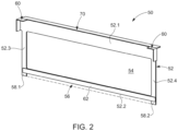
Fig. 2 illustrates the spacer used in assembling the battery stack ofFigure 1 . - Features of the inventive concept and methods of accomplishing the same may be understood more readily by reference to the following detailed description of an embodiment and the accompanying drawings. The present invention, however, may be embodied in various different forms, and should not be construed as being limited to only the illustrated embodiment herein. Rather, this embodiment is provided as example so that this disclosure will be thorough and complete, and will fully convey the aspects and features of the present invention to those skilled in the art.
-
Figure 1 illustrates an exploded view on a part of abattery module 100 including abattery stack 110 according to an exemplary embodiment. Thebattery stack 110 will be accompanied in a housing of thebattery module 100. For simplification, the drawing shows only abase plate 120 and aside pad 130 of said housing. Thebattery stack 110 will be placed on thebase plate 120. - The
battery stack 110 includes a plurality ofbattery cells 10 aligned in one direction. A pair ofend plates 12 locks thebattery stack 110. Here, eachbattery cell 10 is a prismatic (or rectangular) cell, the wide flat surfaces of the cells being stacked together to form thebattery stack 110. Eachbattery cell 10 includes abattery case 13 configured for accommodation of an electrode assembly and an electrolyte. Thebattery case 13 is hermetically sealed by acap assembly 14. Thecap assembly 14 is provided with positive andnegative electrode terminals vent 20. Thevent 20 is a safety means of thebattery cell 10, which acts as a passage through which gas generated in thebattery cell 10 is exhausted to the outside of thebattery cell 10. A side surface of thebattery case 13 may be covered with aninsulation foil 22. The positive andnegative electrode terminals battery cells 10 are electrically connected through a bus bar (not shown). Hence, thebattery module 100 may be used as power source unit by electrically connecting the plurality ofbattery cells 10 as one bundle. - The
battery stack 110 further includes a plurality ofspacers 50. Thespacers 50 andbattery cells 10 are arranged alternately in thebattery stack 110.Figure 2 is an enlarged illustration of one of thespacers 50 used in assembling thebattery stack 110 ofFigure 1 . - The
exemplary spacer 50 has a rectangular shape and includes aframe body 52. Theframe body 52 encloses anopening 54, the purpose of which will be explained in more detail below. Theframe body 52 contains a first longitudinal side 52.1, which is located in thebattery stack 110 at the height of thecap assembly 14. A second longitudinal side 52.2 of theframe body 52 faces thebase plate 120 of the housing. The second longitudinal side 52.2 of theexemplary spacer 50 is slightly offset inwards such that asmall gap 56 is provided at the bottom of thespacer 50. Two transverse sides 52.3 and 52.4 connect the two longitudinal sides 52.1 and 52.2 of theframe body 52. A thickness of the frame body 52 - i.e. each of the longitudinal 52.1 and 52.2 and transverse sides 52.3 and 52.4 - may be about 1mm. - The
spacer 50 further includes a pair ofpositioning elements 60 which rise perpendicularly from a plane of theframe body 52 to one side of theframe body 52 and extend over the two corners of the common first longitudinal side 52.1. Here, thepositioning elements 60 have an L-shape and extend about 5mm from the plane of theframe body 52. As shown inFigure 1 , thepositioning elements 60 are positioned horizontally on thecap assembly 14 and vertically on the two transverse sides of thebattery case 13 within the finalizedbattery stack 110. Thus, thespacer 50 can be easily stacked onto abattery cell 10 during the assembling process of thebattery stack 110, which allows rapid automatization of the process step. - Further, an
adhesive layer 62 is provided on the same side surface of theframe body 52 from which thepositioning elements 60 extend. Here, theadhesive layer 62 is provided on a side surface of a second longitudinal side 52.2. After thespacer 50 has been placed on the side of thebattery cell 10, theadhesive layer 62 adheres to the side surface of thebattery case 13. - The
spacer 50 further comprises adistance element 70 being arranged on the first longitudinal side 52.1 and rising perpendicularly from the plane of theframe body 52 in a direction opposite to thepositioning elements 60. For example, thedistance element 70 may have a length of about 0.75mm. According to the exemplary embodiment, thedistance element 70 is arranged at an outer edge of the first longitudinal side 52.1. Theexemplary distance element 70 has the shape of a bended fold. Thedistance element 70 is used to define a gap on the side of thespacer 50 opposite to the side of thespacer 50 where theadhesive layer 62 and thepositioning elements 60 are provided. In other words, thedistance element 70 provides a small creepage distance between neighbouringbattery cells 10. Generally, thebattery cells 10 generate a large amount of heat while being charged/discharged. The generated heat is accumulated in thebattery cells 10, thereby accelerating the deterioration of thebattery cells 10. Therefore, thebattery module 100 needs to be cooled. The gap defined on one side of thespacer 50 will thus allow to, for example, circulating air to cool thebattery cells 10. - In alternative or addition to the above mentioned embodiment, a thermal conducting material may be provided at a bottom side of the
battery cells 10, respectively on thebase plate 120 of the housing. The thermal conducting material is to enhance a thermal contact between a cooling system provided in a lower part of thebattery module 100 and thesingle battery cells 10. According to one embodiment, the main components of the battery stack 110 - in particular thebatteries cells 10,spacers 50, and end plates 12 - will be assembled along with applying a compression force. Therefore, the longitudinal side 52.2 of theexemplary spacer 50 may be slightly offset inwards such that asmall gap 56 is provided at the bottom of thespacer 50. The free ends 58.1 and 58.2 at the lower transverse sides 52.3 and 52.4 will transmit the force applied to the edges of thestiff battery cells 10 into the thermal conducting material so as to avoid damage of thebattery case 13 due to mechanical stress. Furthermore, the thermal conducting material may spread into thegap 56 at the bottom side of thespacer 50 and may thereby increase a contact surface to thebattery case 13 of thebattery cells 10. The thermal conductive material may be provided as a foil, layer or mat composed, for example, of a plastic material including metallic particles. - During regular operation the
battery cells 10 may expand slightly. The amount of swelling will be at largest in a central area of the side surfaces of thebattery cells 10. Therefore, theopening 54 of thespacer 50 will allow expansion of thebattery cells 10. This avoids accumulation of mechanical stresses at the two ends of thebattery stack 110. - The
frame body 52, thepositioning element 60 as well as thedistance element 70 may be integrally formed, i.e. are provided as one-piece part. The mentioned elements of thespacer 50 may be made of the same plastics, which may be, for example, rigid plastics. -
- 10
- battery cell
- 12
- end plate
- 13
- battery case
- 14
- cap assembly
- 16
- positive electrode terminal
- 18
- negative electrode terminal
- 20
- vent
- 22
- insulation foil
- 50
- spacer
- 52
- frame body
- 52.1, 52.2
- longitudinal sides of the frame body
- 52.3, 52.4
- transverse sides of the frame body
- 54
- opening
- 56
- gap
- 58.1, 58.2
- free ends of the transverse sides
- 60
- positioning element
- 62
- adhesive layer
- 70
- distance element
- 100
- battery module
- 110
- battery stack
- 120
- base plate
- 130
- side pad
Claims (9)
- A spacer (50) for arrangement between two prismatic battery cells (10) of a battery stack (110), the spacer (50) comprising:a rectangular frame body (52) enclosing an opening (54) anda pair of positioning elements (60) which rise perpendicularly from a plane of the frame body (52) to one side of the frame body (52) and extend over the two corners of a common first longitudinal side (52.1) and wherein the spacer (50) further comprises a distance element (70) being arranged on the first longitudinal side (52.1) and rising perpendicularly from the plane of the frame body (52) in a direction opposite to the positioning elements (60), the distance element (70) having a length in the range of 0.5 mm to 1.0 mm.
- The spacer of claim 1, wherein the frame body (52) and the positioning elements (60) are integrally formed.
- The spacer of claim 1 or 2, wherein a thickness of the frame body (52) is in the range of 0.5 mm to 1.5 mm.
- The spacer of claim 1, wherein the distance element (70) is arranged at an outer edge of the first longitudinal side (52.1).
- The spacer of claim 1 or 4, wherein the frame body (52) and the distance element (70) are integrally formed.
- The spacer of any one of the preceding claims, wherein the frame body (52), the positioning elements (60), and/or the distance element (70) are made of plastics.
- The spacer of any one of the preceding claims, wherein an adhesive layer (62) is provided on a side surface of the frame body (52) facing in the same direction as the positioning elements (60).
- The spacer of claim 7, wherein the adhesive layer (62) is provided on a side surface of a second longitudinal side (52.2).
- A battery module (100) comprising a battery stack (110) including an alternating arrangement of battery cells (10) and spacers (50) as defined in any one of the preceding claims.
Priority Applications (5)
| Application Number | Priority Date | Filing Date | Title |
|---|---|---|---|
| HUE19168901A HUE072544T2 (en) | 2019-04-12 | 2019-04-12 | Spacer for a battery stack |
| PL19168901.7T PL3723156T3 (en) | 2019-04-12 | 2019-04-12 | Spacer for a battery stack |
| EP19168901.7A EP3723156B1 (en) | 2019-04-12 | 2019-04-12 | Spacer for a battery stack |
| KR2020200000994U KR20200002327U (en) | 2019-04-12 | 2020-03-23 | Spacer for a battery stack and battery module comprising the battery stack |
| CN202020470552.XU CN212907904U (en) | 2019-04-12 | 2020-04-02 | Spacer for battery stack and battery module including the same |
Applications Claiming Priority (1)
| Application Number | Priority Date | Filing Date | Title |
|---|---|---|---|
| EP19168901.7A EP3723156B1 (en) | 2019-04-12 | 2019-04-12 | Spacer for a battery stack |
Publications (2)
| Publication Number | Publication Date |
|---|---|
| EP3723156A1 EP3723156A1 (en) | 2020-10-14 |
| EP3723156B1 true EP3723156B1 (en) | 2025-07-02 |
Family
ID=66175219
Family Applications (1)
| Application Number | Title | Priority Date | Filing Date |
|---|---|---|---|
| EP19168901.7A Active EP3723156B1 (en) | 2019-04-12 | 2019-04-12 | Spacer for a battery stack |
Country Status (5)
| Country | Link |
|---|---|
| EP (1) | EP3723156B1 (en) |
| KR (1) | KR20200002327U (en) |
| CN (1) | CN212907904U (en) |
| HU (1) | HUE072544T2 (en) |
| PL (1) | PL3723156T3 (en) |
Families Citing this family (7)
| Publication number | Priority date | Publication date | Assignee | Title |
|---|---|---|---|---|
| DE102021207410A1 (en) * | 2021-07-13 | 2023-01-19 | Robert Bosch Gesellschaft mit beschränkter Haftung | Method for manufacturing a battery module and battery module |
| DE102021207406A1 (en) * | 2021-07-13 | 2023-01-19 | Robert Bosch Gesellschaft mit beschränkter Haftung | Battery module and method for manufacturing such |
| JP7654007B2 (en) * | 2021-11-30 | 2025-03-31 | 香港時代新能源科技有限公司 | Battery and its manufacturing method and manufacturing equipment, power consumption device |
| KR20230102737A (en) * | 2021-12-30 | 2023-07-07 | 삼성에스디아이 주식회사 | Rechargeable battery module |
| CN217334279U (en) * | 2022-05-25 | 2022-08-30 | 宁德时代新能源科技股份有限公司 | Battery and power consumption device |
| US20250309488A1 (en) * | 2022-12-02 | 2025-10-02 | Lg Energy Solution, Ltd. | Cell stack assembly and battery pack comprising cell stack assembly |
| EP4633932A1 (en) * | 2022-12-16 | 2025-10-22 | Aerogel R&D Pte. Ltd. | Method and system for manufacturing a thermal insulation device |
Citations (1)
| Publication number | Priority date | Publication date | Assignee | Title |
|---|---|---|---|---|
| US20140120391A1 (en) * | 2012-10-30 | 2014-05-01 | Seong-joon PARK | Battery assembly |
Family Cites Families (7)
| Publication number | Priority date | Publication date | Assignee | Title |
|---|---|---|---|---|
| KR100648697B1 (en) | 2005-03-11 | 2006-11-23 | 삼성에스디아이 주식회사 | Secondary battery module |
| KR101256074B1 (en) * | 2006-07-26 | 2013-04-18 | 삼성에스디아이 주식회사 | Battery module having spacer |
| KR101084933B1 (en) | 2009-12-04 | 2011-11-17 | 삼성에스디아이 주식회사 | Battery spacers for secondary battery modules and secondary battery modules |
| KR101772115B1 (en) * | 2013-09-03 | 2017-08-28 | 삼성에스디아이 주식회사 | Battery pack having movement prevention portion |
| US10224528B2 (en) | 2016-06-17 | 2019-03-05 | Bosch Battery Systems Llc | Battery assembly including spacer |
| JP6878975B2 (en) * | 2017-03-17 | 2021-06-02 | 三洋電機株式会社 | Batteries |
| US11024900B2 (en) * | 2017-04-20 | 2021-06-01 | Ford Global Technologies, Llc | Battery cell support assembly |
-
2019
- 2019-04-12 HU HUE19168901A patent/HUE072544T2/en unknown
- 2019-04-12 PL PL19168901.7T patent/PL3723156T3/en unknown
- 2019-04-12 EP EP19168901.7A patent/EP3723156B1/en active Active
-
2020
- 2020-03-23 KR KR2020200000994U patent/KR20200002327U/en active Pending
- 2020-04-02 CN CN202020470552.XU patent/CN212907904U/en active Active
Patent Citations (1)
| Publication number | Priority date | Publication date | Assignee | Title |
|---|---|---|---|---|
| US20140120391A1 (en) * | 2012-10-30 | 2014-05-01 | Seong-joon PARK | Battery assembly |
Also Published As
| Publication number | Publication date |
|---|---|
| CN212907904U (en) | 2021-04-06 |
| KR20200002327U (en) | 2020-10-22 |
| PL3723156T3 (en) | 2025-10-06 |
| HUE072544T2 (en) | 2025-11-28 |
| EP3723156A1 (en) | 2020-10-14 |
Similar Documents
| Publication | Publication Date | Title |
|---|---|---|
| EP3723156B1 (en) | Spacer for a battery stack | |
| US11699819B2 (en) | Battery cell assembly, battery module including same battery cell assembly, battery pack including same battery module, and automobile including same battery pack | |
| KR101117687B1 (en) | Battery Pack | |
| EP3154103B1 (en) | Battery module including a housing floor with integrated cooling | |
| US9203065B2 (en) | Battery module | |
| CN103843175B (en) | Battery module assembly with improved reliability and battery pack using same | |
| US9640792B2 (en) | Battery assembly having single electrode terminal connection part | |
| CN108701793B (en) | Battery | |
| US12183908B2 (en) | Battery, power consumption device, and method and device for producing battery | |
| US20130034755A1 (en) | Battery module | |
| EP3832752B1 (en) | Power supply device and vehicle having the same | |
| KR20230078513A (en) | Battery module, battery pack and energy storage system comprising the battery module | |
| KR102825392B1 (en) | Batteries, electrical devices, battery manufacturing methods and devices | |
| KR20070025735A (en) | Partition wall of the secondary battery module and the secondary battery module | |
| US20240063479A1 (en) | Battery cell assembly | |
| EP4068447A2 (en) | Power storage | |
| KR20090008087A (en) | Medium and large battery packs with improved safety | |
| EP4376185B1 (en) | Battery pack and method of assembling the same | |
| EP4708503A1 (en) | Battery module with improved stability | |
| US20250141010A1 (en) | Battery Module, and Battery Pack and Vehicle Including the Same | |
| US20250038299A1 (en) | Battery assembly | |
| EP4654339A1 (en) | Battery module, and battery pack and vehicle comprising same | |
| CN121586962A (en) | Battery cell assembly and method of manufacturing the same | |
| CN119856332A (en) | Battery pack | |
| CN120513542A (en) | Battery pack case and method for manufacturing same |
Legal Events
| Date | Code | Title | Description |
|---|---|---|---|
| PUAI | Public reference made under article 153(3) epc to a published international application that has entered the european phase |
Free format text: ORIGINAL CODE: 0009012 |
|
| STAA | Information on the status of an ep patent application or granted ep patent |
Free format text: STATUS: REQUEST FOR EXAMINATION WAS MADE |
|
| 17P | Request for examination filed |
Effective date: 20200430 |
|
| AK | Designated contracting states |
Kind code of ref document: A1 Designated state(s): AL AT BE BG CH CY CZ DE DK EE ES FI FR GB GR HR HU IE IS IT LI LT LU LV MC MK MT NL NO PL PT RO RS SE SI SK SM TR |
|
| AX | Request for extension of the european patent |
Extension state: BA ME |
|
| STAA | Information on the status of an ep patent application or granted ep patent |
Free format text: STATUS: EXAMINATION IS IN PROGRESS |
|
| 17Q | First examination report despatched |
Effective date: 20211102 |
|
| REG | Reference to a national code |
Ref country code: DE Ref legal event code: R079 Free format text: PREVIOUS MAIN CLASS: H01M0002100000 Ipc: H01M0050209000 Ref country code: DE Ref legal event code: R079 Ref document number: 602019071849 Country of ref document: DE Free format text: PREVIOUS MAIN CLASS: H01M0002100000 Ipc: H01M0050209000 |
|
| GRAP | Despatch of communication of intention to grant a patent |
Free format text: ORIGINAL CODE: EPIDOSNIGR1 |
|
| STAA | Information on the status of an ep patent application or granted ep patent |
Free format text: STATUS: GRANT OF PATENT IS INTENDED |
|
| RIC1 | Information provided on ipc code assigned before grant |
Ipc: H01M 50/293 20210101ALI20250212BHEP Ipc: H01M 50/291 20210101ALI20250212BHEP Ipc: H01M 50/209 20210101AFI20250212BHEP |
|
| INTG | Intention to grant announced |
Effective date: 20250314 |
|
| GRAS | Grant fee paid |
Free format text: ORIGINAL CODE: EPIDOSNIGR3 |
|
| GRAA | (expected) grant |
Free format text: ORIGINAL CODE: 0009210 |
|
| STAA | Information on the status of an ep patent application or granted ep patent |
Free format text: STATUS: THE PATENT HAS BEEN GRANTED |
|
| AK | Designated contracting states |
Kind code of ref document: B1 Designated state(s): AL AT BE BG CH CY CZ DE DK EE ES FI FR GB GR HR HU IE IS IT LI LT LU LV MC MK MT NL NO PL PT RO RS SE SI SK SM TR |
|
| REG | Reference to a national code |
Ref country code: GB Ref legal event code: FG4D |
|
| REG | Reference to a national code |
Ref country code: CH Ref legal event code: EP |
|
| REG | Reference to a national code |
Ref country code: DE Ref legal event code: R096 Ref document number: 602019071849 Country of ref document: DE |
|
| REG | Reference to a national code |
Ref country code: IE Ref legal event code: FG4D |
|
| REG | Reference to a national code |
Ref country code: NL Ref legal event code: MP Effective date: 20250702 |
|
| REG | Reference to a national code |
Ref country code: HU Ref legal event code: AG4A Ref document number: E072544 Country of ref document: HU |
|
| PG25 | Lapsed in a contracting state [announced via postgrant information from national office to epo] |
Ref country code: PT Free format text: LAPSE BECAUSE OF FAILURE TO SUBMIT A TRANSLATION OF THE DESCRIPTION OR TO PAY THE FEE WITHIN THE PRESCRIBED TIME-LIMIT Effective date: 20251103 |
|
| PG25 | Lapsed in a contracting state [announced via postgrant information from national office to epo] |
Ref country code: NL Free format text: LAPSE BECAUSE OF FAILURE TO SUBMIT A TRANSLATION OF THE DESCRIPTION OR TO PAY THE FEE WITHIN THE PRESCRIBED TIME-LIMIT Effective date: 20250702 |
|
| PG25 | Lapsed in a contracting state [announced via postgrant information from national office to epo] |
Ref country code: IS Free format text: LAPSE BECAUSE OF FAILURE TO SUBMIT A TRANSLATION OF THE DESCRIPTION OR TO PAY THE FEE WITHIN THE PRESCRIBED TIME-LIMIT Effective date: 20251102 |
|
| PG25 | Lapsed in a contracting state [announced via postgrant information from national office to epo] |
Ref country code: NO Free format text: LAPSE BECAUSE OF FAILURE TO SUBMIT A TRANSLATION OF THE DESCRIPTION OR TO PAY THE FEE WITHIN THE PRESCRIBED TIME-LIMIT Effective date: 20251002 |
|
| REG | Reference to a national code |
Ref country code: LT Ref legal event code: MG9D |
|
| PG25 | Lapsed in a contracting state [announced via postgrant information from national office to epo] |
Ref country code: FI Free format text: LAPSE BECAUSE OF FAILURE TO SUBMIT A TRANSLATION OF THE DESCRIPTION OR TO PAY THE FEE WITHIN THE PRESCRIBED TIME-LIMIT Effective date: 20250702 |
|
| PG25 | Lapsed in a contracting state [announced via postgrant information from national office to epo] |
Ref country code: HR Free format text: LAPSE BECAUSE OF FAILURE TO SUBMIT A TRANSLATION OF THE DESCRIPTION OR TO PAY THE FEE WITHIN THE PRESCRIBED TIME-LIMIT Effective date: 20250702 |
|
| PG25 | Lapsed in a contracting state [announced via postgrant information from national office to epo] |
Ref country code: GR Free format text: LAPSE BECAUSE OF FAILURE TO SUBMIT A TRANSLATION OF THE DESCRIPTION OR TO PAY THE FEE WITHIN THE PRESCRIBED TIME-LIMIT Effective date: 20251003 |
|
| PG25 | Lapsed in a contracting state [announced via postgrant information from national office to epo] |
Ref country code: SE Free format text: LAPSE BECAUSE OF FAILURE TO SUBMIT A TRANSLATION OF THE DESCRIPTION OR TO PAY THE FEE WITHIN THE PRESCRIBED TIME-LIMIT Effective date: 20250702 Ref country code: CZ Free format text: LAPSE BECAUSE OF FAILURE TO SUBMIT A TRANSLATION OF THE DESCRIPTION OR TO PAY THE FEE WITHIN THE PRESCRIBED TIME-LIMIT Effective date: 20250702 |
|
| PG25 | Lapsed in a contracting state [announced via postgrant information from national office to epo] |
Ref country code: LV Free format text: LAPSE BECAUSE OF FAILURE TO SUBMIT A TRANSLATION OF THE DESCRIPTION OR TO PAY THE FEE WITHIN THE PRESCRIBED TIME-LIMIT Effective date: 20250702 |
|
| PG25 | Lapsed in a contracting state [announced via postgrant information from national office to epo] |
Ref country code: BG Free format text: LAPSE BECAUSE OF FAILURE TO SUBMIT A TRANSLATION OF THE DESCRIPTION OR TO PAY THE FEE WITHIN THE PRESCRIBED TIME-LIMIT Effective date: 20250702 |
|
| PG25 | Lapsed in a contracting state [announced via postgrant information from national office to epo] |
Ref country code: RS Free format text: LAPSE BECAUSE OF FAILURE TO SUBMIT A TRANSLATION OF THE DESCRIPTION OR TO PAY THE FEE WITHIN THE PRESCRIBED TIME-LIMIT Effective date: 20251002 |
|
| PG25 | Lapsed in a contracting state [announced via postgrant information from national office to epo] |
Ref country code: ES Free format text: LAPSE BECAUSE OF FAILURE TO SUBMIT A TRANSLATION OF THE DESCRIPTION OR TO PAY THE FEE WITHIN THE PRESCRIBED TIME-LIMIT Effective date: 20250702 |
|
| PG25 | Lapsed in a contracting state [announced via postgrant information from national office to epo] |
Ref country code: SM Free format text: LAPSE BECAUSE OF FAILURE TO SUBMIT A TRANSLATION OF THE DESCRIPTION OR TO PAY THE FEE WITHIN THE PRESCRIBED TIME-LIMIT Effective date: 20250702 |
|
| PG25 | Lapsed in a contracting state [announced via postgrant information from national office to epo] |
Ref country code: DK Free format text: LAPSE BECAUSE OF FAILURE TO SUBMIT A TRANSLATION OF THE DESCRIPTION OR TO PAY THE FEE WITHIN THE PRESCRIBED TIME-LIMIT Effective date: 20250702 |
|
| PG25 | Lapsed in a contracting state [announced via postgrant information from national office to epo] |
Ref country code: IT Free format text: LAPSE BECAUSE OF FAILURE TO SUBMIT A TRANSLATION OF THE DESCRIPTION OR TO PAY THE FEE WITHIN THE PRESCRIBED TIME-LIMIT Effective date: 20250702 |
|
| PGFP | Annual fee paid to national office [announced via postgrant information from national office to epo] |
Ref country code: PL Payment date: 20260327 Year of fee payment: 8 |
|
| PG25 | Lapsed in a contracting state [announced via postgrant information from national office to epo] |
Ref country code: EE Free format text: LAPSE BECAUSE OF FAILURE TO SUBMIT A TRANSLATION OF THE DESCRIPTION OR TO PAY THE FEE WITHIN THE PRESCRIBED TIME-LIMIT Effective date: 20250702 Ref country code: SK Free format text: LAPSE BECAUSE OF FAILURE TO SUBMIT A TRANSLATION OF THE DESCRIPTION OR TO PAY THE FEE WITHIN THE PRESCRIBED TIME-LIMIT Effective date: 20250702 |