EP3723152A1 - Pouch, secondary battery including same, and method for manufacturing secondary battery - Google Patents
Pouch, secondary battery including same, and method for manufacturing secondary battery Download PDFInfo
- Publication number
- EP3723152A1 EP3723152A1 EP19854733.3A EP19854733A EP3723152A1 EP 3723152 A1 EP3723152 A1 EP 3723152A1 EP 19854733 A EP19854733 A EP 19854733A EP 3723152 A1 EP3723152 A1 EP 3723152A1
- Authority
- EP
- European Patent Office
- Prior art keywords
- pouch
- sealing
- accommodation
- protection
- protection part
- Prior art date
- Legal status (The legal status is an assumption and is not a legal conclusion. Google has not performed a legal analysis and makes no representation as to the accuracy of the status listed.)
- Pending
Links
Images







Classifications
-
- H—ELECTRICITY
- H01—ELECTRIC ELEMENTS
- H01M—PROCESSES OR MEANS, e.g. BATTERIES, FOR THE DIRECT CONVERSION OF CHEMICAL ENERGY INTO ELECTRICAL ENERGY
- H01M50/00—Constructional details or processes of manufacture of the non-active parts of electrochemical cells other than fuel cells, e.g. hybrid cells
- H01M50/30—Arrangements for facilitating escape of gases
- H01M50/317—Re-sealable arrangements
- H01M50/325—Re-sealable arrangements comprising deformable valve members, e.g. elastic or flexible valve members
-
- H—ELECTRICITY
- H01—ELECTRIC ELEMENTS
- H01M—PROCESSES OR MEANS, e.g. BATTERIES, FOR THE DIRECT CONVERSION OF CHEMICAL ENERGY INTO ELECTRICAL ENERGY
- H01M50/00—Constructional details or processes of manufacture of the non-active parts of electrochemical cells other than fuel cells, e.g. hybrid cells
- H01M50/10—Primary casings; Jackets or wrappings
- H01M50/102—Primary casings; Jackets or wrappings characterised by their shape or physical structure
- H01M50/105—Pouches or flexible bags
-
- H—ELECTRICITY
- H01—ELECTRIC ELEMENTS
- H01M—PROCESSES OR MEANS, e.g. BATTERIES, FOR THE DIRECT CONVERSION OF CHEMICAL ENERGY INTO ELECTRICAL ENERGY
- H01M50/00—Constructional details or processes of manufacture of the non-active parts of electrochemical cells other than fuel cells, e.g. hybrid cells
- H01M50/10—Primary casings; Jackets or wrappings
- H01M50/183—Sealing members
- H01M50/186—Sealing members characterised by the disposition of the sealing members
-
- H—ELECTRICITY
- H01—ELECTRIC ELEMENTS
- H01M—PROCESSES OR MEANS, e.g. BATTERIES, FOR THE DIRECT CONVERSION OF CHEMICAL ENERGY INTO ELECTRICAL ENERGY
- H01M50/00—Constructional details or processes of manufacture of the non-active parts of electrochemical cells other than fuel cells, e.g. hybrid cells
- H01M50/30—Arrangements for facilitating escape of gases
-
- H—ELECTRICITY
- H01—ELECTRIC ELEMENTS
- H01M—PROCESSES OR MEANS, e.g. BATTERIES, FOR THE DIRECT CONVERSION OF CHEMICAL ENERGY INTO ELECTRICAL ENERGY
- H01M50/00—Constructional details or processes of manufacture of the non-active parts of electrochemical cells other than fuel cells, e.g. hybrid cells
- H01M50/30—Arrangements for facilitating escape of gases
- H01M50/394—Gas-pervious parts or elements
-
- H—ELECTRICITY
- H01—ELECTRIC ELEMENTS
- H01M—PROCESSES OR MEANS, e.g. BATTERIES, FOR THE DIRECT CONVERSION OF CHEMICAL ENERGY INTO ELECTRICAL ENERGY
- H01M10/00—Secondary cells; Manufacture thereof
- H01M10/04—Construction or manufacture in general
- H01M10/0436—Small-sized flat cells or batteries for portable equipment
-
- H—ELECTRICITY
- H01—ELECTRIC ELEMENTS
- H01M—PROCESSES OR MEANS, e.g. BATTERIES, FOR THE DIRECT CONVERSION OF CHEMICAL ENERGY INTO ELECTRICAL ENERGY
- H01M10/00—Secondary cells; Manufacture thereof
- H01M10/04—Construction or manufacture in general
- H01M10/049—Processes for forming or storing electrodes in the battery container
-
- H—ELECTRICITY
- H01—ELECTRIC ELEMENTS
- H01M—PROCESSES OR MEANS, e.g. BATTERIES, FOR THE DIRECT CONVERSION OF CHEMICAL ENERGY INTO ELECTRICAL ENERGY
- H01M50/00—Constructional details or processes of manufacture of the non-active parts of electrochemical cells other than fuel cells, e.g. hybrid cells
- H01M50/10—Primary casings; Jackets or wrappings
- H01M50/116—Primary casings; Jackets or wrappings characterised by the material
- H01M50/124—Primary casings; Jackets or wrappings characterised by the material having a layered structure
-
- H—ELECTRICITY
- H01—ELECTRIC ELEMENTS
- H01M—PROCESSES OR MEANS, e.g. BATTERIES, FOR THE DIRECT CONVERSION OF CHEMICAL ENERGY INTO ELECTRICAL ENERGY
- H01M50/00—Constructional details or processes of manufacture of the non-active parts of electrochemical cells other than fuel cells, e.g. hybrid cells
- H01M50/30—Arrangements for facilitating escape of gases
- H01M50/317—Re-sealable arrangements
-
- Y—GENERAL TAGGING OF NEW TECHNOLOGICAL DEVELOPMENTS; GENERAL TAGGING OF CROSS-SECTIONAL TECHNOLOGIES SPANNING OVER SEVERAL SECTIONS OF THE IPC; TECHNICAL SUBJECTS COVERED BY FORMER USPC CROSS-REFERENCE ART COLLECTIONS [XRACs] AND DIGESTS
- Y02—TECHNOLOGIES OR APPLICATIONS FOR MITIGATION OR ADAPTATION AGAINST CLIMATE CHANGE
- Y02E—REDUCTION OF GREENHOUSE GAS [GHG] EMISSIONS, RELATED TO ENERGY GENERATION, TRANSMISSION OR DISTRIBUTION
- Y02E60/00—Enabling technologies; Technologies with a potential or indirect contribution to GHG emissions mitigation
- Y02E60/10—Energy storage using batteries
-
- Y—GENERAL TAGGING OF NEW TECHNOLOGICAL DEVELOPMENTS; GENERAL TAGGING OF CROSS-SECTIONAL TECHNOLOGIES SPANNING OVER SEVERAL SECTIONS OF THE IPC; TECHNICAL SUBJECTS COVERED BY FORMER USPC CROSS-REFERENCE ART COLLECTIONS [XRACs] AND DIGESTS
- Y02—TECHNOLOGIES OR APPLICATIONS FOR MITIGATION OR ADAPTATION AGAINST CLIMATE CHANGE
- Y02P—CLIMATE CHANGE MITIGATION TECHNOLOGIES IN THE PRODUCTION OR PROCESSING OF GOODS
- Y02P70/00—Climate change mitigation technologies in the production process for final industrial or consumer products
- Y02P70/50—Manufacturing or production processes characterised by the final manufactured product
Definitions
- the present invention relates a pouch, a secondary battery comprising the same, and method for manufacturing the secondary battery, and more particularly, to a pouch that is capable of protecting a sealing part and an accommodation part thereof without folding the sealing part and the accommodation part, a secondary battery comprising the same, and a method for manufacturing the secondary battery.
- secondary batteries refer to chargeable and dischargeable batteries, unlike primary batteries that are not chargeable.
- Such a secondary battery is being widely used in the high-tech electronic fields such as mobile phones, notebook computers, and camcorders.
- Such a secondary battery is classified into a can type secondary battery in which an electrode assembly is built in a metal can and a pouch type secondary battery in which an electrode assembly is built in a pouch.
- the pouch type secondary battery comprises an electrode assembly in which an electrode and a separator are alternately stacked, an electrolyte, and a pouch accommodating the electrode assembly and the electrolyte.
- the pouch comprises an accommodation part accommodating the electrode assembly and an electrolyte and a sealing part sealing the accommodation part.
- the pouch type secondary battery has a problem in that the sealing part and the accommodation part of the pouch are deformed while being easily folded by an external impact. Particularly, when the accommodation part is deformed, the electrode assembly accommodated in the accommodation part may be damaged to cause short circuit or ignition.
- an object of the present invention is to provide a pouch that is capable of preventing a sealing part and an accommodation part thereof from being deformed by providing a protection part outside the pouch, thereby preventing an electrode assembly accommodated in the accommodation part from being damaged, a secondary battery comprising the pouch, and a method for manufacturing the secondary battery.
- a pouch according to a first embodiment of the present invention comprises: an accommodation part configured to accommodate an electrode assembly; a sealing part provided outside the accommodation part, the sealing part having a plurality of sealing surfaces configured to seal the accommodation part; and a protection part provided outside one or more sealing surfaces of the sealing surfaces of the sealing part, the protection part being configured to protect the one or more sealing surfaces.
- the protection part may be provided with one or more protrusions for reinforcing strength.
- the protrusions may be provided by allowing a portion of the protection part to protrude outward or by attaching a component made of a synthetic resin material to the protection part.
- the protrusions may be disposed on both ends of the protection part, which are close to a corner portion of the accommodation part or on both ends of the protection part, which are adjacent to the corner portion of the accommodation part.
- the protection part may be provided on the sealing surface disposed on one side or each of both sides in a width direction of the pouch.
- the pouch may further comprise a gas pocket part configured to collect a gas generated in the accommodation part, wherein the accommodation part may be provided at one side in a width direction of the pouch, and the gas pocket part may be provided at the other side, and the protection part may be provided on each of the sealing surface disposed at one side of the accommodation part and the sealing surface disposed at the other side of the gas pocket part in the width direction of the pouch.
- a secondary battery comprises: an electrode assembly; and a pouch configured to accommodate the electrode assembly, wherein the pouch comprises: an accommodation part configured to accommodate an electrode assembly; a sealing part provided outside the accommodation part, the sealing part having a plurality of sealing surfaces configured to seal the accommodation part; and a protection part provided outside one or more sealing surfaces of the sealing surfaces of the sealing part, the protection part being configured to protect the one or more sealing surfaces.
- the protection part may be removed from each of the sealing surfaces after the pouch, in which the electrode assembly is accommodated, is completely transferred.
- the protection part may not be thermally fused.
- a method for manufacturing a secondary battery according to the second embodiment of the present invention comprises: a pouch sheet preparation step (S10) of preparing a pouch sheet on which an upper pouch and a lower pouch are formed with respect to a horizontal center line that equalizes the pouch sheet vertically; an accommodation part forming step (S20) of forming an upper accommodation part and a lower accommodation part, which respectively correspond to the upper pouch and the lower pouch; a protection part formation step (S30) of forming one or more protrusions that protrude outside from left and right ends of the upper pouch and the lower pouch to form a protection part; an accommodation part formation step (S40) of folding the upper pouch and the lower pouch with respect to the horizontal center line so that the upper and lower accommodation parts are connected to each other to form an accommodation part: and a sealing part formation step (S50) of sealing a portion between the accommodation part and the protection part and upper and lower ends of the accommodation part to manufacture the secondary battery.
- the accommodation part forming step (S20) and the protection part formation step (S30) may be performed at the same time.
- the sealing part formation step (S50) may further comprise a process of further sealing a portion between the accommodation part and the sealing part to form a gas pocket part between the accommodation part and the sealing part, and the accommodation part and the gas pocket part may be connected to each other through a non-sealed path.
- the method may further comprise, after the sealing part formation step (S50), a transfer step (S60) of accommodating the secondary battery in a tray to transfer the secondary battery, wherein the secondary battery may be accommodated so that the protection part is supported by a side surface of a bottom surface of the tray.
- the method may further comprise, after the transfer step (S60), a protection part removing step (S70) of removing the protection part from each of the sealing surfaces of the pouch.
- the method may further comprise, after the removing step (S70), a sealing part resealing step (S80) of resealing the sealing part from which the protection part is removed.
- the protection part may not be sealed.
- the present invention has the feature in which the protection part is disposed outside the pouch. Due to this feature, the sealing part and the accommodation part, which are provided in the pouch, may be protected to prevent deformation such as the bucking or the folding of the sealing part and the accommodation part from occurring, in particular, prevent the electrode assembly accommodated in the accommodation part from being damaged.
- the protection part of the present invention may further comprise the one or more protrusions.
- the protection part may be reinforced in strength to significantly prevent the sealing part and the accommodation part of the pouch from being deformed.
- the protrusion of the present invention may be formed by allowing a portion of the protection part from protruding outside.
- the protrusion may be easily formed to simplify the process and reduce the process cost.
- the protrusion of the present invention may be detachably attached to one side of the protrusion part.
- the protrusion may be selectively attached or separated to improve convenience and efficiency of use.
- the protrusion of the present invention may be formed at the end of the protection part, which is close or adjacent to the corner portion of the accommodation part.
- the corner portion of the accommodation part which may be easily deformed, may be more stably protected to prevent the corner portion of the electrode assembly, which is disposed at the corner portion of the accommodation part, from being damaged.
- the protection part of the present invention may be provided at one side or both sides of the pouch in the width direction. That is, the protection part may be formed at only the portion of the secondary battery, which contacts the jig or the tray, to simplify the process and reduce the process cost.
- a pouch 120 according to a first embodiment of the present invention comprises an accommodation part 121 accommodating an electrode assembly 110 and a sealing part 122 provided along an edge of the accommodation part 121 to seal the accommodation part 121.
- the sealing part 122 comprises a plurality of sealing surfaces for sealing the accommodation part 121.
- the plurality of sealing surfaces comprise a first sealing surface 122a disposed on each of both side surfaces in a width direction (in a left and right direction when viewed in FIG. 1 ) of the electrode assembly accommodation part 121 and a second sealing surface 122b disposed on each of top and bottoms surfaces (upper and lower portions of the accommodation part when viewed in FIG. 1 ) of the accommodation part 121.
- the pouch 120 comprises a gas pocket part 124 for collecting a gas generated in the accommodation part 121.
- the gas pocket part 124 is provided between the accommodation part 121 and the first sealing surface 122a provided on the right surface of the pouch and is separated from the accommodation part 121 by an auxiliary sealing surface 122c in which an inlet hole 122c-1 is defined.
- the accommodation part 121 is provided at a left side, and the gas pocket part 124 is provided at the right side.
- the sealing part 122 is disposed on edge surfaces of the accommodation part 121 and the gas pocket part 124, and the auxiliary sealing surface 122c is disposed between the accommodation part 121 and the gas pocket part 124.
- the pouch is transferred through a jig or a tray.
- the sealing part and the accommodation part of the pouch may be buckled or folded by the jig or the tray.
- even the electrode assembly may be damaged.
- the pouch 120 comprises a protection part that protects the sealing part while increasing in a width of the sealing part.
- the pouch 120 according to the first embodiment of the present invention comprises the protection part 123 that is provided outside one or more sealing surfaces of the sealing part 122 to protect the one or more sealing surfaces.
- a first sealing surface 122a disposed outside the pouch 120 may increase in width, and simultaneously, be improved in strength of the first sealing surface 122a to protect the first sealing surface 122a through the protection part 123.
- the jig when the jig holds the pouch, the jig may hold the sealing part 122 and the protection part 123 together to prevent the accommodation part from being held, thereby preventing the accommodation part from being deformed.
- the protection part 123 when the tray 30 transfers the pouch, the protection part 123 may be supported by a wall of the tray 30 to prevent the sealing part from being directly supported by the tray 30, thereby preventing the sealing part 122 and the accommodation part 121 from being folded by folding of the protection part 123 due to an impact acting on the tray 30.
- the pouch 120 further comprises the protection part 123.
- the deformation of the accommodation part 121 and the sealing part 122 may be prevented from being deformed to prevent the electrode assembly accommodated in the accommodation part from being damaged, thereby improving merchantability.
- the protection part 123 may be integrated with the sealing part 122. That is, the protection part 123 may be integrated with the sealing part 122 when the pouch is manufactured through a pouch sheet, and thus, the process may be simplified, the manufacture may be easy, and the cost may be reduced.
- the protection part 123 may comprise one or more protrusions 123a for reinforcing the strength. That is, a portion of a surface of the protection part 123 may be formed to protrude outside, thereby forming one or more protrusions 123a. Accordingly, the strength of the protection part 123 may be reinforced through the protrusion 123a, and thus, the strength of the sealing part 122 that is close or adjacent to the protection part 123 may be reinforced.
- the protrusion 123a may protrude toward front and rear sides of the protection part 123 to form a sealing space 123-1 therein.
- a reinforcement component 123b made of a synthetic resin material having elastic restoring force may be inserted into the sealing space 123-1 to reinforce the strength of the protrusion 123a.
- the reinforcement component 123b may be recovered from the protrusion 123a and then reused when the protection part 123 is removed from the sealing part.
- An impact detection sensor that detects impact force transmitted from the tray may be inserted into the sealing space 123-1.
- the impact detection sensor measures the impact force transmitted from the tray to the pouch, and when the measured impact force is equal to or greater than inputted impact force, the impact detection sensor outputs a signal to sort out normal and defective products. That is, when the impact force measured by the impact detection sensor is less than the inputted impact force, it may be determined that no deformation occurs in the protection part, and thus, the signal may not be outputted. When the measured impact force is equal to or greater than the inputted impact force, it may be determined that the deformation is highly likely to occur in the sealing part and the accommodation part together with the protection part, and thus, the signal may be outputted.
- the protrusion 123a has a circular shape when viewed in FIG. 2 . That is, the circular protrusion 123a may have a curved outer circumferential surface to effectively disperse a transmitted impact, thereby significantly preventing the protrusion 123a from being folded.
- the protrusion may have various shapes such as a triangular shape, a square shape, a polygon shape, a ring shape, and the like. That is, the protrusion of the present invention may be realized according to various embodiments.
- the protrusion 123a may be disposed on one end or both ends of the protection part 123, which is/are close or adjacent to the corner portion of the accommodation part 121. That is, the pouch 120 has large buckling or folding at the corner portion of the accommodation part 121, and thus, the protrusion 123a is disposed on the end of the protection part 123, which is close or adjacent to the corner portion of the accommodation part 121 to more stably protect the corner portion of the accommodation part 121.
- the protection part 123 may be removed from the sealing part 122. That is, the protection part 123 is removed from the pouch 120 by cutting a portion between the first sealing surface 122a and the protection part 123 to reduce a volume of the pouch 120.
- a cutting line 123c having a groove or protrusion shape may be formed between the first sealing surface 122a and the protection part 123, and the protection part may be easily cut from the pouch 120 through the cutting line 123c.
- the protection unit 123 is not thermally fused. That is, since the protection part 123 is removed after the pouch is transferred, the protection part 123 is not thermally fused to simplify a process and reduce a process cost.
- a secondary battery 100 according to a second embodiment of the present invention comprises the pouch 120 according to the first embodiment.
- the secondary battery 100 according to the second embodiment of the present invention comprises an electrode assembly 110 and a pouch 120 accommodating the electrode assembly 110.
- the electrode assembly 110 comprises a plurality of electrodes that are stacked in a state of interposing a separator therebetween, and the plurality of electrodes comprise a positive electrode and a negative electrode. Also, the electrode assembly 110 comprises an electrode tab that is withdrawn out of the pouch 120.
- the pouch 120 comprises an accommodation part 121 accommodating the electrode assembly 110, a sealing part 122 provided along an edge of the accommodation part 121 to seal the accommodation part 121, a gas pocket part 124 provided between the accommodation part 121 and the sealing part 122 to collect a gas generated in the accommodation part 121, and a protection part 123 provided outside the sealing part 122 to protect the accommodation part 121 together with the sealing part 122.
- the pouch 120 has the same configuration and function as the pouch according to the second embodiment, and thus a detailed description thereof will be omitted.
- the sealing part and the accommodation part of the pouch may be prevented from being deformed, for example, buckled or folded by an impact, thereby preventing the electrode assembly from being damaged.
- a sealing surface from which the protection part 123 is removed is resealed. That is, the sealing surface may be deformed while the protection part 123 is removed, and thus, sealing force may be reduced.
- the sealing surface may be resealed after the protection part 123 is removed, and thus, the sealing force of the pouch 120 may increase.
- a method for manufacturing the secondary battery according to the second embodiment of the present invention comprises a pouch sheet preparation step (S10), an accommodation part forming step (S20), a protection part formation step (S30), an accommodation part formation step (S40), and a sealing part formation step (S50).
- a pouch sheet 10 having a sheet shape is prepared, and a horizontal center line O that equalizes the pouch sheet 10 vertically is displayed on the pouch sheet 10. Then, the pouch sheet 10 is separated into an upper pouch 11 and a lower pouch 12 on the basis of the horizontal center line O.
- a cutting line 123c is displayed on each of left and right ends of the upper pouch 11 and the lower pouch 12 to form a protection part 123 having a predetermined width.
- the width of the protection part is less than a width between the protection part and the accommodation part. This is done because the width between the protection part and the accommodation part becomes the sealing part so that the width of the sealing part is secured to be greater than that of the protection part to increase in sealing force.
- the protection part 123 when the protection part 123 is formed, a portion of a surface of the protection part 123 is formed to protrude outward, thereby forming one or more protrusions 123a.
- the protrusion 123a is formed on a surface of the protection part 123, which is close or adjacent to a corner portion of the accommodation part in which deformation largely occurs.
- the protrusions 123a formed on the protection parts 123 of the upper pouch 11 and the lower pouch 12 may be connected to each other when the pouch sheet 10 is folded with respect to the horizontal center line O.
- the accommodation part forming step (S20) and the protection part formation step (S30) may be performed at the same time to simplify the process. That is, the upper accommodation part 11a and the lower accommodation part 12a, which correspond to the upper pouch 11 and the lower pouch 12, are formed, and simultaneously, the one or more protrusions 123a are formed on the surface of the protection part 123.
- the pouch sheet 10 is folded with respect to the horizontal center line O. Then, the pouch 120 is formed while the upper pouch 11 and the lower pouch 12 are folded, and the accommodation part 121 is formed while the upper accommodation part 11a and the lower accommodation part 12a are connected to each other.
- the electrode assembly 110 is accommodated in the accommodation part 121, and then, upper and lower ends of the accommodation part 121 are sealed between the accommodation part 121 and the protection part 123. Then, the accommodation part 121 may be sealed while the sealing part 122 is formed on an edge surface of the pouch 120, and thus, the secondary battery 100 may be manufactured.
- the sealing part formation step (S50) may further comprise a process of forming a gas pocket part between the accommodation part 121 and the sealing part. That is, in the gas pocket part formation process, sealing is further performed between the accommodation part 121 and the sealing part 122 to form an auxiliary sealing surface 122c in which an inlet hole 122c-1 is formed.
- the accommodation part 121 is formed at a left side
- the gas pocket part 124 is formed at a right side with respect to the auxiliary sealing surface 122c.
- the protection part 123 may not be sealed because the protection part 123 is removed after the secondary battery is transferred, and thus, adding of unnecessary processes may be prevented.
- a transfer step (S60) of transferring the secondary battery 100 to an activation process is further performed.
- the secondary battery 100 is accommodated in one or more trays 30 that move along a conveyor belt.
- the secondary battery 100 is accommodated so that the protection part 123 is supported on a sidewall or a bottom surface of the tray 30 to prevent the sealing part 122 and the accommodation part 121 of the pouch 120 from being directly supported on the sidewall or the bottom surface of the tray, thereby significantly preventing the sealing part 122 and the accommodation part 121 of the pouch 120 from being deformed, for example, buckled or folded.
- the protection part 123 may comprise the one or more protrusions 123a to significantly prevent the sealing part and the accommodation part of the pouch 120 from being deformed.
- a protection part removing step (S70) of removing the protection part may be further performed.
- the protection part removing step (S70) when the transfer of the secondary battery 100 is completed, the function of the protection part 123 is lost, and thus, the protection part 123 may be cut to be removed from the sealing part 122.
- a sealing part resealing step (S80) of resealing the sealing part 122 from which the protection part 123 is removed may be further performed.
- the sealing surface from which the protection part 123 is removed is resealed to increase in sealing force.
- the protection part when the secondary battery is manufactured, may be formed to prevent the electrode assembly accommodated in the secondary battery from being damaged when the secondary battery is transferred, thereby significantly improving quality of the product.
- a protrusion 123a is disposed on a protection part 123.
- the protrusion 123a is lengthily disposed in a longitudinal direction of the protection part 123.
- the protrusion 123a disposed on the protection part 123 increases in length to improve strength of the protection part 123.
- a protrusion 123a is disposed on a protection part 123.
- the protrusion 123a is provided as a separate component and thus is detachably attached to a surface of the protection part 123.
- the pouch 120B according to the fourth embodiment of the present invention may comprise the protrusion 123a that is detachably attached to the surface of the protection part 123 to increase in reusability and convenience.
- the protrusion 123a may move to a portion that is weak in strength on the surface of the protection part and then be attached to the portion.
- a protrusion 123a is disposed on a protection part 123.
- the protrusion 123a crosses front and rear surfaces of the protection part 123 in a zigzag manner without corresponding to the front and rear surfaces to increase in strength of an entire surface of the protection part 123 by using the minimum protrusion 123a.
Landscapes
- Chemical & Material Sciences (AREA)
- Chemical Kinetics & Catalysis (AREA)
- Electrochemistry (AREA)
- General Chemical & Material Sciences (AREA)
- Engineering & Computer Science (AREA)
- Manufacturing & Machinery (AREA)
- Sealing Battery Cases Or Jackets (AREA)
- Secondary Cells (AREA)
Abstract
Description
- The present application claims the benefit of the priority of Korean Patent Application No.
10-2018-0103911, filed on August 31, 2018 - The present invention relates a pouch, a secondary battery comprising the same, and method for manufacturing the secondary battery, and more particularly, to a pouch that is capable of protecting a sealing part and an accommodation part thereof without folding the sealing part and the accommodation part, a secondary battery comprising the same, and a method for manufacturing the secondary battery.
- In general, secondary batteries refer to chargeable and dischargeable batteries, unlike primary batteries that are not chargeable. Such a secondary battery is being widely used in the high-tech electronic fields such as mobile phones, notebook computers, and camcorders.
- Such a secondary battery is classified into a can type secondary battery in which an electrode assembly is built in a metal can and a pouch type secondary battery in which an electrode assembly is built in a pouch. The pouch type secondary battery comprises an electrode assembly in which an electrode and a separator are alternately stacked, an electrolyte, and a pouch accommodating the electrode assembly and the electrolyte. Also, the pouch comprises an accommodation part accommodating the electrode assembly and an electrolyte and a sealing part sealing the accommodation part.
- However, the pouch type secondary battery has a problem in that the sealing part and the accommodation part of the pouch are deformed while being easily folded by an external impact. Particularly, when the accommodation part is deformed, the electrode assembly accommodated in the accommodation part may be damaged to cause short circuit or ignition.
- The present invention has been invented to solve the above problems, an object of the present invention is to provide a pouch that is capable of preventing a sealing part and an accommodation part thereof from being deformed by providing a protection part outside the pouch, thereby preventing an electrode assembly accommodated in the accommodation part from being damaged, a secondary battery comprising the pouch, and a method for manufacturing the secondary battery.
- To achieve the above-described objects, a pouch according to a first embodiment of the present invention comprises: an accommodation part configured to accommodate an electrode assembly; a sealing part provided outside the accommodation part, the sealing part having a plurality of sealing surfaces configured to seal the accommodation part; and a protection part provided outside one or more sealing surfaces of the sealing surfaces of the sealing part, the protection part being configured to protect the one or more sealing surfaces.
- The protection part may be provided with one or more protrusions for reinforcing strength.
- The protrusions may be provided by allowing a portion of the protection part to protrude outward or by attaching a component made of a synthetic resin material to the protection part.
- The protrusions may be disposed on both ends of the protection part, which are close to a corner portion of the accommodation part or on both ends of the protection part, which are adjacent to the corner portion of the accommodation part.
- The protection part may be provided on the sealing surface disposed on one side or each of both sides in a width direction of the pouch.
- The pouch may further comprise a gas pocket part configured to collect a gas generated in the accommodation part, wherein the accommodation part may be provided at one side in a width direction of the pouch, and the gas pocket part may be provided at the other side, and the protection part may be provided on each of the sealing surface disposed at one side of the accommodation part and the sealing surface disposed at the other side of the gas pocket part in the width direction of the pouch.
- A secondary battery according to a second embodiment of the present invention comprises: an electrode assembly; and a pouch configured to accommodate the electrode assembly, wherein the pouch comprises: an accommodation part configured to accommodate an electrode assembly; a sealing part provided outside the accommodation part, the sealing part having a plurality of sealing surfaces configured to seal the accommodation part; and a protection part provided outside one or more sealing surfaces of the sealing surfaces of the sealing part, the protection part being configured to protect the one or more sealing surfaces.
- The protection part may be removed from each of the sealing surfaces after the pouch, in which the electrode assembly is accommodated, is completely transferred.
- The protection part may not be thermally fused.
- A method for manufacturing a secondary battery according to the second embodiment of the present invention comprises: a pouch sheet preparation step (S10) of preparing a pouch sheet on which an upper pouch and a lower pouch are formed with respect to a horizontal center line that equalizes the pouch sheet vertically; an accommodation part forming step (S20) of forming an upper accommodation part and a lower accommodation part, which respectively correspond to the upper pouch and the lower pouch; a protection part formation step (S30) of forming one or more protrusions that protrude outside from left and right ends of the upper pouch and the lower pouch to form a protection part; an accommodation part formation step (S40) of folding the upper pouch and the lower pouch with respect to the horizontal center line so that the upper and lower accommodation parts are connected to each other to form an accommodation part: and a sealing part formation step (S50) of sealing a portion between the accommodation part and the protection part and upper and lower ends of the accommodation part to manufacture the secondary battery.
- The accommodation part forming step (S20) and the protection part formation step (S30) may be performed at the same time.
- The sealing part formation step (S50) may further comprise a process of further sealing a portion between the accommodation part and the sealing part to form a gas pocket part between the accommodation part and the sealing part, and the accommodation part and the gas pocket part may be connected to each other through a non-sealed path.
- The method may further comprise, after the sealing part formation step (S50), a transfer step (S60) of accommodating the secondary battery in a tray to transfer the secondary battery, wherein the secondary battery may be accommodated so that the protection part is supported by a side surface of a bottom surface of the tray.
- The method may further comprise, after the transfer step (S60), a protection part removing step (S70) of removing the protection part from each of the sealing surfaces of the pouch.
- The method may further comprise, after the removing step (S70), a sealing part resealing step (S80) of resealing the sealing part from which the protection part is removed.
- In the sealing part formation step (S50), the protection part may not be sealed.
- The present invention has the feature in which the protection part is disposed outside the pouch. Due to this feature, the sealing part and the accommodation part, which are provided in the pouch, may be protected to prevent deformation such as the bucking or the folding of the sealing part and the accommodation part from occurring, in particular, prevent the electrode assembly accommodated in the accommodation part from being damaged.
- Also, the protection part of the present invention may further comprise the one or more protrusions. Thus, the protection part may be reinforced in strength to significantly prevent the sealing part and the accommodation part of the pouch from being deformed.
- Also, the protrusion of the present invention may be formed by allowing a portion of the protection part from protruding outside. Thus, the protrusion may be easily formed to simplify the process and reduce the process cost.
- The protrusion of the present invention may be detachably attached to one side of the protrusion part. Thus, the protrusion may be selectively attached or separated to improve convenience and efficiency of use.
- Also, the protrusion of the present invention may be formed at the end of the protection part, which is close or adjacent to the corner portion of the accommodation part. Thus, the corner portion of the accommodation part, which may be easily deformed, may be more stably protected to prevent the corner portion of the electrode assembly, which is disposed at the corner portion of the accommodation part, from being damaged.
- Also, the protection part of the present invention may be provided at one side or both sides of the pouch in the width direction. That is, the protection part may be formed at only the portion of the secondary battery, which contacts the jig or the tray, to simplify the process and reduce the process cost.
-
-
FIG. 1 is a perspective view of a pouch according to a first embodiment of the present invention. -
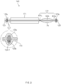
FIG. 2 is a front view of the pouch according to the first embodiment of the present invention. -
FIG. 3 is a cross-sectional view taken along line A-A ofFIG. 1 ; -
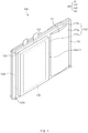
FIG. 4 is a perspective view of a secondary battery according to a second embodiment of the present invention. -
FIG. 5 is a front view illustrating a state in which a protection part is removed from the secondary battery according to the second embodiment of the present invention. -
FIG. 6 is a flowchart illustrating a method for manufacturing the second battery according to the second embodiment of the present invention. -
FIG. 7 is a perspective view illustrating a pouch sheet preparation step, an accommodation part forming step, and a protection part formation step. -
FIG. 8 is a perspective view illustrating an electrode assembly accommodation part formation step. -
FIG. 9 is a front view illustrating a sealing formation step. -
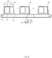
FIG. 10 is a side view illustrating a secondary battery transfer step. -
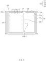
FIG. 11 is a front view illustrating a protection part removing step and a sealing part resealing step. -
FIG. 12 is a front view of a pouch according to a third embodiment of the present invention. -
FIG. 13 is a cross-sectional view of a pouch according to a fourth embodiment of the present invention. -
FIG. 14 is a perspective view of a pouch according to a fifth embodiment of the present invention. - Hereinafter, embodiments of the present invention will be described in detail with reference to the accompanying drawings in such a manner that the technical idea of the present invention may easily be carried out by a person with ordinary skill in the art to which the invention pertains. The present invention may, however, be embodied in different forms and should not be construed as limited to the embodiments set forth herein. In the drawings, anything unnecessary for describing the present invention will be omitted for clarity, and also like reference numerals in the drawings denote like elements.
- As illustrated in
FIGS. 1 to 3 , apouch 120 according to a first embodiment of the present invention comprises anaccommodation part 121 accommodating anelectrode assembly 110 and asealing part 122 provided along an edge of theaccommodation part 121 to seal theaccommodation part 121. - Here, the sealing
part 122 comprises a plurality of sealing surfaces for sealing theaccommodation part 121. As illustrated inFIG. 1 , the plurality of sealing surfaces comprise afirst sealing surface 122a disposed on each of both side surfaces in a width direction (in a left and right direction when viewed inFIG. 1 ) of the electrodeassembly accommodation part 121 and asecond sealing surface 122b disposed on each of top and bottoms surfaces (upper and lower portions of the accommodation part when viewed inFIG. 1 ) of theaccommodation part 121. - Also, the
pouch 120 according to the first embodiment of the present invention comprises agas pocket part 124 for collecting a gas generated in theaccommodation part 121. Referring toFIG. 1 , thegas pocket part 124 is provided between theaccommodation part 121 and thefirst sealing surface 122a provided on the right surface of the pouch and is separated from theaccommodation part 121 by anauxiliary sealing surface 122c in which aninlet hole 122c-1 is defined. - In summary, in the
pouch 120 according to the first embodiment of the present invention, theaccommodation part 121 is provided at a left side, and thegas pocket part 124 is provided at the right side. The sealingpart 122 is disposed on edge surfaces of theaccommodation part 121 and thegas pocket part 124, and theauxiliary sealing surface 122c is disposed between theaccommodation part 121 and thegas pocket part 124. - The pouch is transferred through a jig or a tray. Here, the sealing part and the accommodation part of the pouch may be buckled or folded by the jig or the tray. In particular, when the electrode assembly is accommodated in the accommodation part, even the electrode assembly may be damaged.
- In order to solve the above problems, the
pouch 120 according to the first embodiment of the present invention comprises a protection part that protects the sealing part while increasing in a width of the sealing part. - That is, the
pouch 120 according to the first embodiment of the present invention comprises theprotection part 123 that is provided outside one or more sealing surfaces of the sealingpart 122 to protect the one or more sealing surfaces. Afirst sealing surface 122a disposed outside thepouch 120 may increase in width, and simultaneously, be improved in strength of thefirst sealing surface 122a to protect thefirst sealing surface 122a through theprotection part 123. - That is to say, in the
pouch 120 according to the first embodiment, when the jig holds the pouch, the jig may hold the sealingpart 122 and theprotection part 123 together to prevent the accommodation part from being held, thereby preventing the accommodation part from being deformed. Also, referring toFIG. 10 , when thetray 30 transfers the pouch, theprotection part 123 may be supported by a wall of thetray 30 to prevent the sealing part from being directly supported by thetray 30, thereby preventing the sealingpart 122 and theaccommodation part 121 from being folded by folding of theprotection part 123 due to an impact acting on thetray 30. - As described above, the
pouch 120 according to the first embodiment of the present invention further comprises theprotection part 123. Thus, the deformation of theaccommodation part 121 and the sealingpart 122 may be prevented from being deformed to prevent the electrode assembly accommodated in the accommodation part from being damaged, thereby improving merchantability. - The
protection part 123 may be integrated with the sealingpart 122. That is, theprotection part 123 may be integrated with the sealingpart 122 when the pouch is manufactured through a pouch sheet, and thus, the process may be simplified, the manufacture may be easy, and the cost may be reduced. - The
protection part 123 may comprise one ormore protrusions 123a for reinforcing the strength. That is, a portion of a surface of theprotection part 123 may be formed to protrude outside, thereby forming one ormore protrusions 123a. Accordingly, the strength of theprotection part 123 may be reinforced through theprotrusion 123a, and thus, the strength of the sealingpart 122 that is close or adjacent to theprotection part 123 may be reinforced. - Referring to the enlarged view of
FIG. 3 , theprotrusion 123a may protrude toward front and rear sides of theprotection part 123 to form a sealing space 123-1 therein. Areinforcement component 123b made of a synthetic resin material having elastic restoring force may be inserted into the sealing space 123-1 to reinforce the strength of theprotrusion 123a. Here, thereinforcement component 123b may be recovered from theprotrusion 123a and then reused when theprotection part 123 is removed from the sealing part. - An impact detection sensor that detects impact force transmitted from the tray may be inserted into the sealing space 123-1. The impact detection sensor measures the impact force transmitted from the tray to the pouch, and when the measured impact force is equal to or greater than inputted impact force, the impact detection sensor outputs a signal to sort out normal and defective products. That is, when the impact force measured by the impact detection sensor is less than the inputted impact force, it may be determined that no deformation occurs in the protection part, and thus, the signal may not be outputted. When the measured impact force is equal to or greater than the inputted impact force, it may be determined that the deformation is highly likely to occur in the sealing part and the accommodation part together with the protection part, and thus, the signal may be outputted.
- In particular, the
protrusion 123a has a circular shape when viewed inFIG. 2 . That is, thecircular protrusion 123a may have a curved outer circumferential surface to effectively disperse a transmitted impact, thereby significantly preventing theprotrusion 123a from being folded. - Here, although the circular protrusion is described as one embodiment of the present invention, the protrusion may have various shapes such as a triangular shape, a square shape, a polygon shape, a ring shape, and the like. That is, the protrusion of the present invention may be realized according to various embodiments.
- The
protrusion 123a may be disposed on one end or both ends of theprotection part 123, which is/are close or adjacent to the corner portion of theaccommodation part 121. That is, thepouch 120 has large buckling or folding at the corner portion of theaccommodation part 121, and thus, theprotrusion 123a is disposed on the end of theprotection part 123, which is close or adjacent to the corner portion of theaccommodation part 121 to more stably protect the corner portion of theaccommodation part 121. - When the transfer of the
pouch 120 is completed, theprotection part 123 may be removed from the sealingpart 122. That is, theprotection part 123 is removed from thepouch 120 by cutting a portion between thefirst sealing surface 122a and theprotection part 123 to reduce a volume of thepouch 120. - A
cutting line 123c having a groove or protrusion shape may be formed between thefirst sealing surface 122a and theprotection part 123, and the protection part may be easily cut from thepouch 120 through thecutting line 123c. - The
protection unit 123 is not thermally fused. That is, since theprotection part 123 is removed after the pouch is transferred, theprotection part 123 is not thermally fused to simplify a process and reduce a process cost. - Hereinafter, in descriptions of another embodiment of the present invention, constituents having the same function as the abovementioned embodiment have been given the same reference numeral in the drawings, and thus duplicated description will be omitted.
- A
secondary battery 100 according to a second embodiment of the present invention comprises thepouch 120 according to the first embodiment. - That is, as illustrated in
FIG. 4 , thesecondary battery 100 according to the second embodiment of the present invention comprises anelectrode assembly 110 and apouch 120 accommodating theelectrode assembly 110. - The
electrode assembly 110 comprises a plurality of electrodes that are stacked in a state of interposing a separator therebetween, and the plurality of electrodes comprise a positive electrode and a negative electrode. Also, theelectrode assembly 110 comprises an electrode tab that is withdrawn out of thepouch 120. - The
pouch 120 comprises anaccommodation part 121 accommodating theelectrode assembly 110, a sealingpart 122 provided along an edge of theaccommodation part 121 to seal theaccommodation part 121, agas pocket part 124 provided between theaccommodation part 121 and the sealingpart 122 to collect a gas generated in theaccommodation part 121, and aprotection part 123 provided outside the sealingpart 122 to protect theaccommodation part 121 together with the sealingpart 122. - Here, the
pouch 120 has the same configuration and function as the pouch according to the second embodiment, and thus a detailed description thereof will be omitted. - When the
secondary battery 100 having the above-described configuration according to the second embodiment of the present invention is transferred, the sealing part and the accommodation part of the pouch may be prevented from being deformed, for example, buckled or folded by an impact, thereby preventing the electrode assembly from being damaged. - As illustrated in
FIG. 5 , in thesecondary battery 100 according to the second embodiment of the present invention, when theprotection part 123 is removed from the sealingpart 122, a sealing surface from which theprotection part 123 is removed is resealed. That is, the sealing surface may be deformed while theprotection part 123 is removed, and thus, sealing force may be reduced. In order to solve the above-described problem, the sealing surface may be resealed after theprotection part 123 is removed, and thus, the sealing force of thepouch 120 may increase. - A method for manufacturing the secondary battery having the above-described configuration according to the second embodiment of the present invention will be described as follows.
- As illustrated in
FIG. 6 , a method for manufacturing the secondary battery according to the second embodiment of the present invention comprises a pouch sheet preparation step (S10), an accommodation part forming step (S20), a protection part formation step (S30), an accommodation part formation step (S40), and a sealing part formation step (S50). - As illustrated in
FIG. 7 , in the pouch sheet preparation step (S10), apouch sheet 10 having a sheet shape is prepared, and a horizontal center line O that equalizes thepouch sheet 10 vertically is displayed on thepouch sheet 10. Then, thepouch sheet 10 is separated into anupper pouch 11 and alower pouch 12 on the basis of the horizontal center line O. - In the accommodation part forming step (S20), each of an
upper accommodation part 11a and alower accommodation part 12a, which respectively correspond to theupper pouch 11 and thelower pouch 12, is formed. That is, when thepouch sheet 10 is folded with respect to the horizontal center line O, theupper accommodation part 11a of theupper pouch 11 and thelower accommodation part 12a of thelower pouch 12 are formed to be connected to each other. - In the protection part formation step (S30), a
cutting line 123c is displayed on each of left and right ends of theupper pouch 11 and thelower pouch 12 to form aprotection part 123 having a predetermined width. Here, the width of the protection part is less than a width between the protection part and the accommodation part. This is done because the width between the protection part and the accommodation part becomes the sealing part so that the width of the sealing part is secured to be greater than that of the protection part to increase in sealing force. - The, when the
protection part 123 is formed, a portion of a surface of theprotection part 123 is formed to protrude outward, thereby forming one ormore protrusions 123a. In particular, theprotrusion 123a is formed on a surface of theprotection part 123, which is close or adjacent to a corner portion of the accommodation part in which deformation largely occurs. - Here, the
protrusions 123a formed on theprotection parts 123 of theupper pouch 11 and thelower pouch 12 may be connected to each other when thepouch sheet 10 is folded with respect to the horizontal center line O. - The accommodation part forming step (S20) and the protection part formation step (S30) may be performed at the same time to simplify the process. That is, the
upper accommodation part 11a and thelower accommodation part 12a, which correspond to theupper pouch 11 and thelower pouch 12, are formed, and simultaneously, the one ormore protrusions 123a are formed on the surface of theprotection part 123. - In the accommodation part formation step (S40), as illustrated in
FIG. 8 , thepouch sheet 10 is folded with respect to the horizontal center line O. Then, thepouch 120 is formed while theupper pouch 11 and thelower pouch 12 are folded, and theaccommodation part 121 is formed while theupper accommodation part 11a and thelower accommodation part 12a are connected to each other. - As illustrated in
FIG. 9 , in the sealing part formation step (S50), theelectrode assembly 110 is accommodated in theaccommodation part 121, and then, upper and lower ends of theaccommodation part 121 are sealed between theaccommodation part 121 and theprotection part 123. Then, theaccommodation part 121 may be sealed while the sealingpart 122 is formed on an edge surface of thepouch 120, and thus, thesecondary battery 100 may be manufactured. - Here, the sealing part formation step (S50) may further comprise a process of forming a gas pocket part between the
accommodation part 121 and the sealing part. That is, in the gas pocket part formation process, sealing is further performed between theaccommodation part 121 and the sealingpart 122 to form anauxiliary sealing surface 122c in which aninlet hole 122c-1 is formed. In summary, in thepouch 120, theaccommodation part 121 is formed at a left side, and thegas pocket part 124 is formed at a right side with respect to theauxiliary sealing surface 122c. - The
protection part 123 may not be sealed because theprotection part 123 is removed after the secondary battery is transferred, and thus, adding of unnecessary processes may be prevented. - After the sealing part formation step (S50), a transfer step (S60) of transferring the
secondary battery 100 to an activation process is further performed. - That is, as illustrated in
FIG. 10 , in the transfer step (S60), thesecondary battery 100 is accommodated in one ormore trays 30 that move along a conveyor belt. Here, thesecondary battery 100 is accommodated so that theprotection part 123 is supported on a sidewall or a bottom surface of thetray 30 to prevent the sealingpart 122 and theaccommodation part 121 of thepouch 120 from being directly supported on the sidewall or the bottom surface of the tray, thereby significantly preventing the sealingpart 122 and theaccommodation part 121 of thepouch 120 from being deformed, for example, buckled or folded. In particular, theprotection part 123 may comprise the one ormore protrusions 123a to significantly prevent the sealing part and the accommodation part of thepouch 120 from being deformed. - After the transfer step (S60), a protection part removing step (S70) of removing the protection part may be further performed.
- That is, as illustrated in
FIG. 11 , in the protection part removing step (S70), when the transfer of thesecondary battery 100 is completed, the function of theprotection part 123 is lost, and thus, theprotection part 123 may be cut to be removed from the sealingpart 122. - After the removing step (S70), a sealing part resealing step (S80) of resealing the sealing
part 122 from which theprotection part 123 is removed may be further performed. - That is, in the sealing part resealing step (S80), the sealing surface from which the
protection part 123 is removed is resealed to increase in sealing force. - In the method for manufacturing the secondary battery, which comprises the above-described steps, according to the second embodiment of the present invention, when the secondary battery is manufactured, the protection part may be formed to prevent the electrode assembly accommodated in the secondary battery from being damaged when the secondary battery is transferred, thereby significantly improving quality of the product.
- As illustrated in
FIG. 12 , in apouch 120A according to a third embodiment of the present invention, aprotrusion 123a is disposed on aprotection part 123. Here, theprotrusion 123a is lengthily disposed in a longitudinal direction of theprotection part 123. - That is, in the
pouch 120A according to the third embodiment of the present invention, theprotrusion 123a disposed on theprotection part 123 increases in length to improve strength of theprotection part 123. - As illustrated in
FIG. 13 , in apouch 120B according to a fourth embodiment of the present invention, aprotrusion 123a is disposed on aprotection part 123. Here, theprotrusion 123a is provided as a separate component and thus is detachably attached to a surface of theprotection part 123. - That is, the
pouch 120B according to the fourth embodiment of the present invention may comprise theprotrusion 123a that is detachably attached to the surface of theprotection part 123 to increase in reusability and convenience. In particular, theprotrusion 123a may move to a portion that is weak in strength on the surface of the protection part and then be attached to the portion. - As illustrated in
FIG. 14 , apouch 120C according to a fifth embodiment of the present invention, aprotrusion 123a is disposed on aprotection part 123. Here, theprotrusion 123a crosses front and rear surfaces of theprotection part 123 in a zigzag manner without corresponding to the front and rear surfaces to increase in strength of an entire surface of theprotection part 123 by using theminimum protrusion 123a. - Accordingly, the scope of the present invention is defined by the appended claims more than the foregoing description and the exemplary embodiments described therein. Various modifications made within the meaning of an equivalent of the claims of the invention and within the claims are to be regarded to be in the scope of the present invention.
Claims (15)
- A pouch comprising:an accommodation part configured to accommodate an electrode assembly;a sealing part provided outside the accommodation part, the sealing part having a plurality of sealing surfaces configured to seal the accommodation part; anda protection part provided outside one or more sealing surfaces of the sealing surfaces of the sealing part, the protection part being configured to protect the one or more sealing surfaces.
- The pouch of claim 1, wherein the protection part is provided with one or more protrusions for reinforcing strength.
- The pouch of claim 2, wherein the protrusions is provided by allowing a portion of the protection part to protrude outward or by attaching a component made of a synthetic resin material to the protection part.
- The pouch of claim 2, wherein the protrusions are disposed on both ends of the protection part, which are close to a corner portion of the accommodation part or on both ends of the protection part, which are adjacent to the corner portion of the accommodation part.
- The pouch of claim 2, wherein the protection part is provided on the sealing surface disposed on one side or each of both sides in a width direction of the pouch.
- The pouch of claim 1, further comprising a gas pocket part configured to collect a gas generated in the accommodation part,
wherein the accommodation part is provided at one side in a width direction of the pouch, and the gas pocket part is provided at the other side, and
the protection part is provided on each of the sealing surface disposed at one side of the accommodation part and the sealing surface disposed at the other side of the gas pocket part in the width direction of the pouch. - A secondary battery comprising:an electrode assembly; anda pouch configured to accommodate the electrode assembly,wherein the pouch comprises:an accommodation part configured to accommodate an electrode assembly;a sealing part provided outside the accommodation part, the sealing part having a pluralityof sealing surfaces configured to seal the accommodation part; and
a protection part provided outside one or more sealing surfaces of the sealing surfaces of the sealing part, the protection part being configured to protect the one or more sealing surfaces. - The secondary battery of claim 7, wherein the protection part is removed from each of the sealing surfaces after the pouch, in which the electrode assembly is accommodated, is completely transferred.
- The secondary battery of claim 7, wherein the protection part is not thermally fused.
- A method for manufacturing a secondary battery, the method comprising:a pouch sheet preparation step (S10) of preparing a pouch sheet on which an upper pouch and a lower pouch are formed with respect to a horizontal center line that equalizes the pouch sheet vertically;an accommodation part forming step (S20) of forming an upper accommodation part and a lower accommodation part, which respectively correspond to the upper pouch and the lower pouch;a protection part formation step (S30) of forming one or more protrusions that protrude outside from left and right ends of the upper pouch and the lower pouch to form a protection part;an accommodation part formation step (S40) of folding the upper pouch and the lower pouch with respect to the horizontal center line so that the upper and lower accommodation parts are connected to each other to form an accommodation part: anda sealing part formation step (S50) of sealing a portion between the accommodation part and the protection part and upper and lower ends of the accommodation part to manufacture the secondary battery.
- The method of claim 10, wherein the sealing part formation step (S50) further comprises a process of further sealing a portion between the accommodation part and the sealing part to form a gas pocket part between the accommodation part and the sealing part, and
the accommodation part and the gas pocket part are connected to each other through a non-sealed path. - The method of claim 10, further comprising, after the sealing part formation step (S50), a transfer step (S60) of accommodating the secondary battery in a tray to transfer the secondary battery,
wherein the secondary battery is accommodated so that the protection part is supported by a side surface of a bottom surface of the tray. - The method of claim 12, further comprising, after the transfer step (S60), a protection part removing step (S70) of removing the protection part from each of the sealing surfaces of the pouch.
- The method of claim 13, further comprising, after the removing step (S70), a sealing part resealing step (S80) of resealing the sealing part from which the protection part is removed.
- The method of claim 13, wherein, in the sealing part formation step (S50), the protection part is not sealed.
Applications Claiming Priority (2)
| Application Number | Priority Date | Filing Date | Title |
|---|---|---|---|
| KR1020180103911A KR102527981B1 (en) | 2018-08-31 | 2018-08-31 | Pouch, secondary battery comprising the same and manufacturing method of secondary battery |
| PCT/KR2019/011090 WO2020046018A1 (en) | 2018-08-31 | 2019-08-29 | Pouch, secondary battery including same, and method for manufacturing secondary battery |
Publications (2)
| Publication Number | Publication Date |
|---|---|
| EP3723152A1 true EP3723152A1 (en) | 2020-10-14 |
| EP3723152A4 EP3723152A4 (en) | 2021-03-24 |
Family
ID=69645269
Family Applications (1)
| Application Number | Title | Priority Date | Filing Date |
|---|---|---|---|
| EP19854733.3A Pending EP3723152A4 (en) | 2018-08-31 | 2019-08-29 | POCKET, SECONDARY BATTERY INCLUDING IT AND SECONDARY BATTERY MANUFACTURING PROCESS |
Country Status (5)
| Country | Link |
|---|---|
| US (2) | US11791517B2 (en) |
| EP (1) | EP3723152A4 (en) |
| KR (1) | KR102527981B1 (en) |
| CN (1) | CN111602260B (en) |
| WO (1) | WO2020046018A1 (en) |
Families Citing this family (9)
| Publication number | Priority date | Publication date | Assignee | Title |
|---|---|---|---|---|
| KR102807656B1 (en) * | 2020-05-13 | 2025-05-14 | 주식회사 엘지에너지솔루션 | Rechargeable battery |
| KR102884176B1 (en) * | 2020-05-20 | 2025-11-12 | 주식회사 엘지에너지솔루션 | Pouch type secondary battery having the Pressure Measuring Device for measuring the internal pressure |
| KR102850160B1 (en) * | 2020-06-24 | 2025-08-25 | 주식회사 엘지에너지솔루션 | Secondary battery and method for manufacturing the same |
| KR102855609B1 (en) * | 2020-06-24 | 2025-09-05 | 주식회사 엘지에너지솔루션 | Pouch for secondary battery and method for manufacturing the same |
| KR102861228B1 (en) * | 2020-11-03 | 2025-09-18 | 주식회사 엘지에너지솔루션 | Sheet for Battery Case Having Gas Pocket Portion Formed Along Moving Direction, Battery Cell Manufactured Using the Same, and Method for Manufacturing the Battery Cell |
| EP4270610B1 (en) * | 2020-12-23 | 2026-04-22 | LG Energy Solution, Ltd. | Secondary battery pouch, manufacturing method thereof, and secondary battery manufacturing method |
| KR102782786B1 (en) * | 2020-12-23 | 2025-03-19 | 주식회사 엘지에너지솔루션 | Pouch for secondary battery, method of manufacturing thereof and manufacturing method of secondary battery |
| KR20240076472A (en) * | 2022-11-22 | 2024-05-30 | 에스케이온 주식회사 | Intermediate assembly of pouch type secondary battery and method for manufacturing pouch type secondary battery |
| KR20240079515A (en) * | 2022-11-29 | 2024-06-05 | 에스케이온 주식회사 | Pouch unit and battery cell including the same |
Family Cites Families (26)
| Publication number | Priority date | Publication date | Assignee | Title |
|---|---|---|---|---|
| JP2000173563A (en) | 1998-12-03 | 2000-06-23 | Tokai Rubber Ind Ltd | Thin battery bag |
| KR100573094B1 (en) | 1999-05-31 | 2006-04-24 | 삼성에스디아이 주식회사 | Lithium Polymer Battery and Manufacturing Method Thereof |
| KR20040005022A (en) | 2002-07-08 | 2004-01-16 | 삼성에스디아이 주식회사 | Case for secondary battery and die forming the same |
| KR20040054128A (en) | 2002-12-17 | 2004-06-25 | 삼성에스디아이 주식회사 | Pouched-type lithium secondary battery |
| KR100958649B1 (en) | 2002-12-27 | 2010-05-20 | 삼성에스디아이 주식회사 | Battery unit, a winding method thereof, and a lithium secondary battery manufactured using the same |
| JP4445737B2 (en) | 2003-10-06 | 2010-04-07 | 日本電気株式会社 | Laminated battery, protective member for the laminated battery, and battery unit |
| KR100553753B1 (en) | 2003-10-16 | 2006-02-20 | 삼성에스디아이 주식회사 | Pouch Type Secondary Battery |
| US7682735B2 (en) * | 2005-03-28 | 2010-03-23 | Samsung Sdi Co., Ltd. | Pouch type lithium secondary battery and method of fabricating the same |
| KR100948970B1 (en) | 2006-03-13 | 2010-03-23 | 주식회사 엘지화학 | Medium and large battery module with shock absorbing member |
| KR100876455B1 (en) | 2006-07-31 | 2008-12-29 | 주식회사 엘지화학 | Pouch type secondary battery with unsealed surplus |
| US8771866B2 (en) | 2010-03-30 | 2014-07-08 | Samsung Sdi Co., Ltd. | Pouch type secondary battery and the fabrication method thereof |
| KR101304870B1 (en) * | 2010-12-02 | 2013-09-06 | 주식회사 엘지화학 | Method for Manufacturing Battery Cell and Battery Cell Manufactured Thereby |
| KR101428458B1 (en) * | 2012-01-04 | 2014-08-11 | 주식회사 엘지화학 | Secondary Battery of Structure Having Raised Portion at Sealing Part and Manufacturing Method thereof |
| CN202495539U (en) | 2012-01-09 | 2012-10-17 | 宁德新能源科技有限公司 | Lithium ion battery |
| KR101897223B1 (en) * | 2012-04-24 | 2018-09-12 | 에스케이이노베이션 주식회사 | Pouch type secondary battery |
| KR20130134963A (en) * | 2012-05-31 | 2013-12-10 | 주식회사 엘지화학 | Pouch having a gas pocket portion for battery, and degassing process using the same |
| CN202687165U (en) | 2012-06-21 | 2013-01-23 | 惠州Tcl金能电池有限公司 | Polymer soft package lithium ion battery and structure for preventing aluminum plastic film corner position damage of polymer soft package lithium ion battery |
| US20140212701A1 (en) | 2013-01-29 | 2014-07-31 | Samsung Sdi Co., Ltd. | Battery cell |
| KR101595611B1 (en) | 2013-03-22 | 2016-02-18 | 주식회사 엘지화학 | a secondary battery for improving energy degree |
| JP2015069959A (en) | 2013-10-01 | 2015-04-13 | 株式会社デンソー | Assembled battery |
| JP6202753B2 (en) | 2014-07-01 | 2017-09-27 | 藤森工業株式会社 | Battery container, film packaging battery, and battery container manufacturing method |
| KR101863703B1 (en) | 2014-10-20 | 2018-06-01 | 주식회사 엘지화학 | Pouch-type secondary battery and method for manufacturing the same |
| KR102092071B1 (en) | 2016-02-03 | 2020-04-14 | 주식회사 엘지화학 | Method for Preparing Battery Pack Having Fixing Structure Made of Thermoplastic Resin and Apparatus for Manufacturing the Same |
| KR101775451B1 (en) | 2016-02-03 | 2017-09-07 | 세방전지(주) | Integrated sensing board for battery pack |
| CN106207020A (en) | 2016-08-30 | 2016-12-07 | 南通鼎鑫电池有限公司 | The protecting band of a kind of polymer Li-ion battery and means of defence thereof |
| KR102103899B1 (en) * | 2017-05-24 | 2020-04-24 | 주식회사 엘지화학 | Secondary battery and manufactury methode for the same |
-
2018
- 2018-08-31 KR KR1020180103911A patent/KR102527981B1/en active Active
-
2019
- 2019-08-29 EP EP19854733.3A patent/EP3723152A4/en active Pending
- 2019-08-29 US US16/961,422 patent/US11791517B2/en active Active
- 2019-08-29 CN CN201980008386.1A patent/CN111602260B/en active Active
- 2019-08-29 WO PCT/KR2019/011090 patent/WO2020046018A1/en not_active Ceased
-
2023
- 2023-04-25 US US18/139,169 patent/US12401087B2/en active Active
Also Published As
| Publication number | Publication date |
|---|---|
| US20230268607A1 (en) | 2023-08-24 |
| US20200373535A1 (en) | 2020-11-26 |
| CN111602260B (en) | 2023-10-13 |
| EP3723152A4 (en) | 2021-03-24 |
| KR20200025909A (en) | 2020-03-10 |
| US12401087B2 (en) | 2025-08-26 |
| CN111602260A (en) | 2020-08-28 |
| US11791517B2 (en) | 2023-10-17 |
| KR102527981B1 (en) | 2023-05-03 |
| WO2020046018A1 (en) | 2020-03-05 |
Similar Documents
| Publication | Publication Date | Title |
|---|---|---|
| US12401087B2 (en) | Pouch, secondary battery comprising the same, and method for manufacturing the secondary battery | |
| KR101440096B1 (en) | Pouch for battery, and pouch type battery including the same | |
| US10532423B2 (en) | Battery pack and method for manufacturing the same | |
| KR100846972B1 (en) | Exterior case of secondary battery and secondary battery using same | |
| US12355035B2 (en) | Secondary battery and method for manufacturing the same | |
| EP2942832B1 (en) | Electrode assembly and battery cell comprising same | |
| JP2018081885A (en) | Power storage device and manufacturing method thereof | |
| EP4037071A1 (en) | Pouch-type secondary battery, battery pack, and method for manufacturing pouch-type secondary battery | |
| US12341202B2 (en) | Pouch type secondary battery, battery pack, and method for manufacturing pouch type secondary battery | |
| EP2385565A1 (en) | Rechargeable battery | |
| US11967734B2 (en) | Electrode assembly, secondary battery comprising the same, method for manufacturing secondary battery, and battery pack | |
| ES2969863T3 (en) | battery pack | |
| EP4138186A1 (en) | Secondary battery, manufacturing method therefor, and battery pack | |
| EP4175050A1 (en) | Secondary battery and manufacturing method therefor | |
| JP7345957B2 (en) | Secondary batteries, secondary battery manufacturing methods, and battery packs containing the secondary batteries | |
| EP4718621A2 (en) | Electrode tab assembly and secondary battery including the same | |
| EP4270610B1 (en) | Secondary battery pouch, manufacturing method thereof, and secondary battery manufacturing method | |
| CN224020946U (en) | battery pack | |
| EP4160797B1 (en) | Tray for secondary battery and tray assembly comprising the same | |
| CN104851991B (en) | Battery and manufacturing method thereof | |
| CN105009324B (en) | Secondary battery frame and battery pack including the same | |
| US20250372795A1 (en) | Battery tape and battery having battery tape attached thereto | |
| EP4481934B1 (en) | Electrode tab jig assembly and electrode tab welding device comprising same | |
| JP2024501303A (en) | Secondary battery case and secondary battery | |
| US20240120588A1 (en) | Battery cell cartridge, battery module assembly including the same, and battery pack assembly including the same |
Legal Events
| Date | Code | Title | Description |
|---|---|---|---|
| STAA | Information on the status of an ep patent application or granted ep patent |
Free format text: STATUS: THE INTERNATIONAL PUBLICATION HAS BEEN MADE |
|
| PUAI | Public reference made under article 153(3) epc to a published international application that has entered the european phase |
Free format text: ORIGINAL CODE: 0009012 |
|
| STAA | Information on the status of an ep patent application or granted ep patent |
Free format text: STATUS: REQUEST FOR EXAMINATION WAS MADE |
|
| 17P | Request for examination filed |
Effective date: 20200710 |
|
| AK | Designated contracting states |
Kind code of ref document: A1 Designated state(s): AL AT BE BG CH CY CZ DE DK EE ES FI FR GB GR HR HU IE IS IT LI LT LU LV MC MK MT NL NO PL PT RO RS SE SI SK SM TR |
|
| AX | Request for extension of the european patent |
Extension state: BA ME |
|
| REG | Reference to a national code |
Ref country code: DE Ref legal event code: R079 Free format text: PREVIOUS MAIN CLASS: H01M0002020000 Ipc: H01M0010040000 |
|
| A4 | Supplementary search report drawn up and despatched |
Effective date: 20210224 |
|
| RIC1 | Information provided on ipc code assigned before grant |
Ipc: H01M 50/30 20210101ALI20210218BHEP Ipc: H01M 50/105 20210101ALI20210218BHEP Ipc: H01M 10/04 20060101AFI20210218BHEP Ipc: H01M 50/183 20210101ALI20210218BHEP |
|
| DAV | Request for validation of the european patent (deleted) | ||
| DAX | Request for extension of the european patent (deleted) | ||
| RAP1 | Party data changed (applicant data changed or rights of an application transferred) |
Owner name: LG ENERGY SOLUTION LTD. |
|
| RAP3 | Party data changed (applicant data changed or rights of an application transferred) |
Owner name: LG ENERGY SOLUTION, LTD. |
|
| STAA | Information on the status of an ep patent application or granted ep patent |
Free format text: STATUS: EXAMINATION IS IN PROGRESS |
|
| 17Q | First examination report despatched |
Effective date: 20240112 |