EP3723039A1 - Tip attachment discrimination device - Google Patents
Tip attachment discrimination device Download PDFInfo
- Publication number
- EP3723039A1 EP3723039A1 EP18900720.6A EP18900720A EP3723039A1 EP 3723039 A1 EP3723039 A1 EP 3723039A1 EP 18900720 A EP18900720 A EP 18900720A EP 3723039 A1 EP3723039 A1 EP 3723039A1
- Authority
- EP
- European Patent Office
- Prior art keywords
- tip attachment
- controller
- posture
- camera
- work device
- Prior art date
- Legal status (The legal status is an assumption and is not a legal conclusion. Google has not performed a legal analysis and makes no representation as to the accuracy of the status listed.)
- Withdrawn
Links
- 238000001514 detection method Methods 0.000 claims abstract description 117
- 230000036544 posture Effects 0.000 description 78
- 238000000034 method Methods 0.000 description 10
- 230000000694 effects Effects 0.000 description 9
- 230000008602 contraction Effects 0.000 description 5
- 230000006870 function Effects 0.000 description 5
- IUVCFHHAEHNCFT-INIZCTEOSA-N 2-[(1s)-1-[4-amino-3-(3-fluoro-4-propan-2-yloxyphenyl)pyrazolo[3,4-d]pyrimidin-1-yl]ethyl]-6-fluoro-3-(3-fluorophenyl)chromen-4-one Chemical compound C1=C(F)C(OC(C)C)=CC=C1C(C1=C(N)N=CN=C11)=NN1[C@@H](C)C1=C(C=2C=C(F)C=CC=2)C(=O)C2=CC(F)=CC=C2O1 IUVCFHHAEHNCFT-INIZCTEOSA-N 0.000 description 4
- 238000013528 artificial neural network Methods 0.000 description 4
- 238000004088 simulation Methods 0.000 description 4
- 238000004364 calculation method Methods 0.000 description 3
- 238000010276 construction Methods 0.000 description 3
- 238000010586 diagram Methods 0.000 description 3
- 238000010801 machine learning Methods 0.000 description 3
- 230000002265 prevention Effects 0.000 description 3
- 238000004422 calculation algorithm Methods 0.000 description 2
- 239000004065 semiconductor Substances 0.000 description 2
- 238000013473 artificial intelligence Methods 0.000 description 1
- 238000009412 basement excavation Methods 0.000 description 1
- 239000000428 dust Substances 0.000 description 1
- 238000003708 edge detection Methods 0.000 description 1
- 238000005516 engineering process Methods 0.000 description 1
- 230000004048 modification Effects 0.000 description 1
- 238000012986 modification Methods 0.000 description 1
- 230000003287 optical effect Effects 0.000 description 1
- 238000012706 support-vector machine Methods 0.000 description 1
Images




Classifications
-
- E—FIXED CONSTRUCTIONS
- E02—HYDRAULIC ENGINEERING; FOUNDATIONS; SOIL SHIFTING
- E02F—DREDGING; SOIL-SHIFTING
- E02F9/00—Component parts of dredgers or soil-shifting machines, not restricted to one of the kinds covered by groups E02F3/00 - E02F7/00
- E02F9/28—Small metalwork for digging elements, e.g. teeth scraper bits
-
- E—FIXED CONSTRUCTIONS
- E02—HYDRAULIC ENGINEERING; FOUNDATIONS; SOIL SHIFTING
- E02F—DREDGING; SOIL-SHIFTING
- E02F3/00—Dredgers; Soil-shifting machines
- E02F3/04—Dredgers; Soil-shifting machines mechanically-driven
- E02F3/28—Dredgers; Soil-shifting machines mechanically-driven with digging tools mounted on a dipper- or bucket-arm, i.e. there is either one arm or a pair of arms, e.g. dippers, buckets
- E02F3/36—Component parts
-
- E—FIXED CONSTRUCTIONS
- E02—HYDRAULIC ENGINEERING; FOUNDATIONS; SOIL SHIFTING
- E02F—DREDGING; SOIL-SHIFTING
- E02F3/00—Dredgers; Soil-shifting machines
- E02F3/04—Dredgers; Soil-shifting machines mechanically-driven
- E02F3/96—Dredgers; Soil-shifting machines mechanically-driven with arrangements for alternate or simultaneous use of different digging elements
-
- E—FIXED CONSTRUCTIONS
- E02—HYDRAULIC ENGINEERING; FOUNDATIONS; SOIL SHIFTING
- E02F—DREDGING; SOIL-SHIFTING
- E02F9/00—Component parts of dredgers or soil-shifting machines, not restricted to one of the kinds covered by groups E02F3/00 - E02F7/00
- E02F9/26—Indicating devices
- E02F9/264—Sensors and their calibration for indicating the position of the work tool
-
- E—FIXED CONSTRUCTIONS
- E02—HYDRAULIC ENGINEERING; FOUNDATIONS; SOIL SHIFTING
- E02F—DREDGING; SOIL-SHIFTING
- E02F9/00—Component parts of dredgers or soil-shifting machines, not restricted to one of the kinds covered by groups E02F3/00 - E02F7/00
- E02F9/26—Indicating devices
- E02F9/267—Diagnosing or detecting failure of vehicles
Definitions
- the present invention relates to a tip attachment discrimination device that discriminates a type of a tip attachment of a work machine.
- Patent Literature 1 describes a technique in which a distance sensor measures a distance distribution including a tip attachment (an attachment in Patent Literature 1) and recognizes the tip attachment based on the distance distribution (see claim 1 of Patent Literature 1).
- the type of the tip attachment and the like are recognized based on the distance distribution, and a distance sensor is used to measure the distance distribution.
- the distance sensor may have higher cost than monocular cameras.
- Patent Literature 1 JP 2017-157016A
- an object of the present invention is to provide a tip attachment discrimination device that can accurately discriminate the type of the tip attachment without using the distance distribution.
- a tip attachment discrimination device is a tip attachment discrimination device of a work machine including: a lower travelling body; an upper slewing body provided above the lower travelling body; and a work device including a tip to which one of different types of tip attachments is attached in a replaceable manner, the work device being attached to the upper slewing body.
- the tip attachment discrimination device includes: a camera attached to the upper slewing body and configured to capture an image within a movable range of the tip attachment; a work device posture sensor configured to detect a posture of the work device; and a controller, in which the controller: sets a detection frame in an area including the tip attachment with respect to the image captured by the camera based on the posture of the work device detected by the work device posture sensor; and discriminates the type of the tip attachment based on the image of the tip attachment within the detection frame.
- FIGS. 1 to 6 a tip attachment discrimination device 1 shown in FIG. 1 will be described.
- the tip attachment discrimination device 1 is a device that automatically discriminates a type of a tip attachment 25, and is provided in a work machine 10.
- the work machine 10 includes a construction machine that performs work such as construction work.
- the work machine 10 such as a hydraulic excavator, a hybrid shovel, a crane, or the like can be employed.
- the work machine 10 includes a lower travelling body 11, an upper slewing body 13, a work device 20, a work device posture sensor 30, and a camera 40.
- the work machine 10 includes a monitor 50 and a controller 60 shown in FIG. 2 .
- a front direction of the upper slewing body 13 is described as forward
- a rear direction of the upper slewing body 13 is described as rearward
- forward and rearward are collectively described as a front-and -rear direction.
- a left side is described as leftward
- a right side is described as rightward
- the left side and the right side are collectively described as a right-and-left direction.
- a direction perpendicular to each of the front-and-rear direction and the right-and-left direction is described as an up-and-down direction.
- An upper side of the up-and-down direction is described as upward
- a lower side of the up-and-down direction is described as downward.
- the lower travelling body 11 includes, for example, a crawler, and causes the work machine 10 to travel.
- a bottom surface 11b of the lower travelling body 11 (bottom surface of the work machine 10) is in contact with the ground plane A.
- the upper slewing body 13 is provided above the lower travelling body 11 and is configured to be pivotable about the up-and-down direction with respect to the lower travelling body 11.
- the upper slewing body 13 includes a cab 13c (driver's cab).
- the work device 20 is a device that is attached to the upper slewing body 13 and performs work.
- the work device 20 includes a boom 21, an arm 23, and the tip attachment 25.
- the boom 21 is rotatably attached to the upper slewing body 13.
- the arm 23 is rotatably attached to the boom 21.
- the tip attachment 25 is provided at a tip of the work device 20.
- the tip attachment 25 is replaceable with different types of tip attachments.
- the types of the tip attachments 25 include a bucket (example shown in FIG. 1 ), a clamshell, a scissor-shaped device, a hammer, a magnet, and the like.
- the tip attachment 25 is rotatably attached to the arm 23.
- a position serving as a reference for the tip attachment 25 is referred to as a reference position 25b.
- the reference position 25b is a position determined regardless of the type of the tip attachment 25.
- the reference position 25b is, for example, a proximal portion of the tip attachment 25, and is, for example, a rotational axis (bucket pin or the like) of the tip attachment 25 with respect to the arm 23.
- the tip attachment 25 is described as "tip ATT.”
- the boom 21, the arm 23, and the tip attachment 25 are driven by a boom cylinder (not shown), an arm cylinder (not shown), and an attachment cylinder (not shown), respectively.
- the work device posture sensor 30 is a sensor that detects a posture of the work device 20 shown in FIG. 1 .
- the work device posture sensor 30 includes a boom angle sensor 31, an arm angle sensor 33, and a tip attachment angle sensor 35.
- the boom angle sensor 31 detects an angle of the boom 21 with respect to the upper slewing body 13 (boom 21 angle).
- the boom angle sensor 31 includes, for example, an angle sensor such as an encoder provided in a proximal portion of the boom 21.
- the boom angle sensor 31 may include, for example, a sensor that detects an expansion and contraction amount of the boom cylinder that drives the boom 21.
- the boom angle sensor 31 is required at least to convert the expansion and contraction amount of the boom cylinder into the boom 21 angle and output the boom 21 angle to the controller 60.
- the boom angle sensor 31 may output the detected expansion and contraction amount to the controller 60, and the controller 60 may convert the expansion and contraction amount into the boom 21 angle.
- the configuration of detecting the angle by detecting the expansion and contraction amount of the cylinder is also applicable to the arm angle sensor 33 and the tip attachment angle sensor 35.
- the arm angle sensor 33 detects the angle of the arm 23 with respect to the boom 21 (arm 23 angle).
- the tip attachment angle sensor 35 detects the angle of the tip attachment 25 with respect to the arm 23 (tip attachment 25 angle).
- the camera 40 (image capturing device) is configured to capture an image within a movable range of the tip attachment 25.
- the camera 40 captures an image of the work device 20 and surroundings thereof.
- the camera 40 is preferably configured to capture the entire range assumed as the movable range of the tip attachment 25.
- the camera 40 may be attached to the upper slewing body 13, for example, may be attached to the cab 13c (for example, upper left front), and may be attached to, for example, a portion of the upper slewing body 13 other than the cab 13c.
- the camera 40 is fixed to the upper slewing body 13.
- the camera 40 may be configured to be movable (for example, pivotable) with respect to the upper slewing body 13.
- the camera 40 may include, for example, a monocular camera.
- the camera 40 is preferably a monocular camera.
- the camera 40 preferably has, for example, a zoom function such as an optical zoom function.
- a zoom position (focal length) of the camera 40 is preferably continuously variable between a telephoto side and a wide-angle side. Note that FIG. 1 shows one example of an angle of view 40a of the camera 40.
- the monitor 50 displays various information items.
- the monitor 50 may display an image captured by the camera 40, for example, as shown in FIG. 4 .
- the monitor 50 may display a detection frame F (see FIG. 4 ). Details of the detection frame F will be described later.
- the monitor 50 may display a discrimination result of the type of the tip attachment 25.
- the controller 60 performs input-output of a signal (information), computation (determination, calculation), and the like.
- the controller 60 includes a first controller 61 (main control unit) and a second controller 62 (auxiliary control unit).
- the first controller 61 includes, for example, a computer including a processor such as a CPU and a memory such as a semiconductor memory, and controls an operation of the work machine 10 (see FIG. 1 ).
- the first controller 61 performs acquisition, processing, storage, and the like of information regarding the work machine 10.
- the first controller 61 is connected to the work device posture sensor 30, the camera 40, and the monitor 50.
- the second controller 62 includes, for example, a computer including a processor such as a CPU and a memory such as a semiconductor memory, and discriminates (identifies) the type of the tip attachment 25 from image information including the tip attachment 25 (see FIG. 4 ).
- the second controller 62 is a recognition unit that executes image recognition by artificial intelligence (AI).
- AI artificial intelligence
- the first controller 61 and the second controller 62 may be integrated into one. At least either one of the first controller 61 and the second controller 62 may be subdivided. For example, the first controller 61 and the second controller 62 may be divided according to different types of function.
- the operation of the tip attachment discrimination device 1 (mainly operation of the controller 60) will be described. Note that in the following, each component of the tip attachment discrimination device 1 (camera 40, controller 60, and the like) will be mainly described with reference to FIG. 1 , and each step of the flowchart will be described with reference to FIG. 3 .
- step S11 the camera 40 captures an image including the tip attachment 25.
- the camera 40 is required at least to capture an image including the tip attachment 25 successively in terms of time.
- the controller 60 acquires the image captured by the camera 40 as shown in FIG. 4 (hereinafter referred to as "camera image Im"). Examples of the camera image Im captured by the camera 40 are shown in FIGS. 4 and 5.
- FIG. 5 shows a remote state in which the tip attachment 25 has become more distant from the camera 40 than in a close state shown in FIG. 4 . Note that in FIGS. 4 and 5 , illustration of portions other than the work machine 10 is omitted.
- the work device posture sensor 30 detects the posture of the work device 20.
- the boom angle sensor 31 detects the boom 21 angle
- the arm angle sensor 33 detects the arm 23 angle
- the tip attachment angle sensor 35 detects the tip attachment 25 angle.
- the first controller 61 of the controller 60 acquires posture information on the work device 20 detected by the work device posture sensor 30.
- the first controller 61 calculates a relative position of the reference position 25b with respect to the upper slewing body 13 based on the boom 21 angle and the arm 23 angle.
- the first controller 61 can calculate the rough position of the tip attachment 25 based on the position of the reference position 25b and the tip attachment 25 angle. Details of this calculation will be described later.
- the first controller 61 sets the detection frame F in the camera image Im as shown in FIG. 4 .
- the detection frame F is a frame within the camera image Im captured by the camera 40 (see FIG. 1 ), and is a frame set in an area including the tip attachment 25.
- the image inside the detection frame F is used for discriminating the type of the tip attachment 25.
- the image outside the detection frame F is not used for discriminating the type of the tip attachment 25.
- the position, size, shape, and the like of the detection frame F in the camera image Im are set as follows.
- the detection frame F is set such that the entire external shape of the tip attachment 25 is included inside the detection frame F.
- the detection frame F is preferably set so as to minimize the background portion within the detection frame F. That is, the detection frame F is preferably set at a size as small as possible and such that the entire external shape of the tip attachment 25 fits inside the detection frame F. For example, the tip attachment 25 preferably appears in the central portion within the detection frame F.
- the position and size of the tip attachment 25 appearing in the camera image Im change depending on the posture of the work device 20. For example, as shown in FIG. 5 , as the tip attachment 25 is more distant from the camera 40, the tip attachment 25 appears smaller in the camera image Im. For example, as the tip attachment 25 is at a higher position, the tip attachment 25 appears at an upper position in the camera image Im. For example, an aspect ratio of the tip attachment 25 in the camera image Im changes depending on the angle of the tip attachment 25 with respect to the arm 23.
- the detection frame F is set based on the posture of the work device 20.
- the detection frame F is set based on the position of the reference position 25b in the camera image Im.
- the position of the reference position 25b in the camera image Im is calculated based on the boom 21 angle and the arm 23 angle.
- the position of the reference position 25b in the camera image Im is acquired based on the position of the reference position 25b with respect to the upper slewing body 13 or the camera 40 shown in FIG. 1 , which is determined based on the boom 21 angle and the arm 23 angle.
- the detection frame F is set based on the tip attachment 25 angle.
- the reference position 25b is calculated as follows, for example.
- the first controller 61 reads, from a memory (not shown), a reference position determination table in which correspondence between the boom 21 angle, the arm 23 angle, and the reference position 25b in the camera image Im is determined in advance. Then, the first controller 61 is required at least to acquire the reference position 25b by identifying the reference position 25b corresponding to the boom 31 angle detected by the boom angle sensor 31 and the arm 23 angle detected by the arm angle sensor 33 from the reference position determination table.
- the reference position determination table is created in advance, for example, by a simulation using the specified work machine 10.
- the camera 40 captures the work device 20 while changing each of the boom 21 angle and the arm 23 angle.
- the position of the reference position 25b is identified in each of the obtained camera images Im, and a plurality of data sets in which the reference position 25b is associated with the boom 21 angle and the arm 23 angle is generated and stored in the position determination table.
- the position determination table is created. Note that this work may be performed by a person or by image processing.
- the detection frame F is set in the camera image Im as described below.
- the first controller 61 reads, from a memory (not shown), a detection frame determination table in which correspondence between the boom 21 angle, the arm 23 angle, the tip attachment 25 angle, and detection frame information indicating the size of the detection frame F is determined in advance.
- the detection frame information includes, for example, the length of the vertical side and the length of the horizontal side of the detection frame F, positioning information indicating a position where the reference position 25b is to be positioned within the detection frame F, and other information.
- the first controller 61 identifies, from the detection frame determination table, the detection frame information corresponding to the boom 21 angle detected by the boom angle sensor 31, the arm 23 angle detected by the arm angle sensor 33, and the tip attachment 25 angle detected by the tip attachment angle sensor 35. Then, the first controller 61 is required at least to set the detection frame F indicated by the identified detection frame information in the camera image Im. At this time, the first controller 61 is required at least to set the detection frame F such that the reference position 25b is positioned at a position within the detection frame F indicated by the positioning information included in the detection frame information.
- the detection frame determination table is created in advance, for example, by a simulation using the specified work machine 10 to which the specified tip attachment 25 such as a bucket is attached.
- the camera 40 captures the work device 20 while changing each of the boom 21 angle, the arm 23 angle, and the tip attachment 25 angle.
- a certain area including the tip attachment 25 is extracted from each of the obtained camera images Im, and the extracted area is set as the detection frame F.
- the detection frame F for example, a quadrilateral area circumscribing the tip attachment 25 in the camera image Im may be employed, or a quadrilateral area slightly larger in size than the circumscribing quadrilateral may be employed. This work may be performed by a person or by image processing.
- the first controller 61 sets the detection frame F based on the posture of the work device 20. Therefore, the first controller 61 does not need to use an object detection algorithm, which is a process for detecting the tip attachment 25, in the entire area of the camera image Im. Therefore, a calculation load of the first controller 61 can be reduced accordingly. Moreover, since it is not necessary to use the object detection algorithm in the entire area of the camera image Im, the detection position of the tip attachment 25 that is subject to type discrimination is not erroneously recognized. For example, it is assumed that a tip attachment 25 different from the tip attachment 25 attached to the arm 23 is positioned within the angle of view of the camera 40 and appears in the camera image Im.
- the other tip attachment 25, which is not attached to the work machine 10 is not subject to type discrimination. Also, in this case, the other tip attachment 25, which is positioned away from the reference position 25b, appears outside the detection frame F in the camera image Im. Therefore, the present embodiment can prevent the other tip attachment 25 from becoming subject to type discrimination.
- the position and size of the tip attachment 25 appearing in the camera image Im change depending on the structure of the work machine 10.
- the position, size, and the like of the tip attachment 25 in the camera image Im change depending on the length of the boom 21 and the length of the arm 23.
- the type of the tip attachment 25 that is assumed to be provided in the work device 20 changes depending on the size of the work machine 10 (for example, "XX ton class"). Then, the position, size, and the like of the tip attachment 25 in the camera image Im change.
- the detection frame F is preferably set based not only on a detection value of the work device posture sensor 30 but also on structure information indicating the structure of the work machine 10.
- the structure information is included in, for example, main specifications of the work machine 10.
- the structure information may be, for example, set (stored) in advance by the first controller 61, or may be acquired by some kind of method.
- the structure information includes, for example, information on the upper slewing body 13, information on the boom 21, and information on the arm 23.
- the structure information includes, for example, the size (dimension) and relative position of each of the upper slewing body 13, the boom 21, and the arm 23.
- the structure information includes the position of the camera 40 with respect to the upper slewing body 13.
- the controller 60 can calculate the posture of the work device 20 more accurately by using not only the detection value of the work device posture sensor 30 but also the structure information on the work machine 10. For example, the controller 60 can calculate the reference position 25b more accurately. As a result, the background portion within the detection frame F can be reduced, and the accuracy of type discrimination of the tip attachment 25 can be improved.
- the first controller 61 can perform processing as in the following [Example A1] or [Example A2].
- the rough detection frame F is set based on the posture of the work device 20 without using the structure information on the work machine 10. Thereafter, the detection frame F may be corrected based on the structure information on the work machine 10.
- the first controller 61 first determines the size of the detection frame F with reference to the detection frame determination table described above. Next, the first controller 61 is required at least to correct the size of the detection frame F by calculating a ratio of weight information on the specified work machine 10 used when creating the detection frame determination table to weight information included in the structure information on the work machine 10, and multiplying the size of the detection frame F identified from the detection frame determination table by the ratio.
- the weight information is information indicating the size of the work machine 10, such as "XX ton class" described above.
- the detection frame F may be set from the beginning based on the structure information on the work machine 10 and the posture of the work device 20 without performing the correction as in [Example A1] described above. Note that the shape of the detection frame F is rectangular in the example shown in FIG. 4 , but may be a polygon, a circle, an ellipse, or a similar shape other than quadrilateral.
- the first controller 61 calculates the reference position 25b in the three-dimensional coordinate system of the work machine 10 by using the length of the boom 21 and the length of the arm 23 included in the structure information, and the boom 21 angle detected by the boom angle sensor 31 and the arm 23 angle detected by the arm angle sensor 33. Then, the first controller 61 calculates the reference position 25b in the camera image Im by projecting the reference position 25b in the three-dimensional coordinate system onto a captured surface of the camera 40. Then, the first controller 61 is required at least to set the detection frame F in the camera image Im by using the detection frame determination table described above. At this time, the controller 60 may correct the size of the detection frame F as shown in Example A1.
- the structure of the work machine 10 is roughly determined and is limited to a certain range. Therefore, even when the controller 60 does not acquire the structure information on the work machine 10, the controller 60 can set the detection frame F to include the tip attachment 25.
- the first controller 61 sequentially changes the setting of the detection frame F according to the change in the posture of the work device 20. Specifically, for example, the detection frame F is changed as follows. When the position of the reference position 25b in the camera image Im changes, the first controller 61 changes the position of the detection frame F according to the changed position of the reference position 25b. When the reference position 25b moves away from the camera 40 and the tip attachment 25 appearing in the camera image Im becomes smaller, the first controller 61 makes the detection frame F smaller. Similarly, when the reference position 25b comes closer to the camera 40 and the tip attachment 25 appearing in the camera image Im becomes larger, the controller 60 makes the detection frame F larger.
- the first controller 61 changes the aspect ratio of the detection frame F.
- a quadrilateral area circumscribing the tip attachment 25 appearing in the camera image Im or a quadrilateral area slightly larger in size than the circumscribing quadrilateral is set as the detection frame F. Therefore, if the detection frame F is set using the detection frame determination table, the size of the detection frame F is set smaller as the reference position 25b moves away from the camera 40, and the size of the detection frame F is set larger as the reference position 25b comes closer to the camera 40.
- step S31 the first controller 61 determines whether the position of the tip attachment 25 is a position that can be in a dead angle for the camera 40 as shown in FIG. 6 .
- the tip attachment 25 may be in a dead angle for the camera 40.
- the first controller 61 stores information in which a predetermined posture condition is set in advance in a memory.
- the predetermined posture condition is a condition of the posture of the work device 20 and a condition in which the position of the tip attachment 25 can be in a dead angle for the camera 40.
- this is a condition in which at least part of the tip attachment 25 can be disposed on the Z2 side opposite to the Z1 side where the camera 40 is disposed with respect to the ground plane A of the work machine 10.
- the ground plane A is a virtual plane parallel to the bottom surface 11b and including the bottom surface 11b.
- the "Z2 side" is a lower side of the ground plane A.
- the predetermined posture condition may be the posture of the work device 20 in which the largest tip attachment 25 among the tip attachments 25 assumed to be provided in the work device 20 is disposed on the Z2 side of the ground plane A.
- the predetermined posture condition may be set based on the distance from the ground plane A to the reference position 25b.
- the first controller 61 determines the position of the tip of the tip attachment 25 from the boom 21 angle, the arm 23 angle, and the tip attachment 25 angle respectively detected by the boom angle sensor 31, the arm angle sensor 33, and the tip attachment angle sensor 35. Then, when the distance in the up-and-down direction between the position of the tip of the tip attachment 25 and the reference position 25b is longer than the distance in the up-and-down direction from the reference position 25b to the ground plane A, the first controller 61 may determine that the predetermined posture condition is satisfied.
- step S33 in order to perform type discrimination of the tip attachment 25.
- the first controller 61 when the posture of the work device 20 satisfies the predetermined posture condition (YES in S31), the first controller 61 does not perform type discrimination of the tip attachment 25. In this case, the current flow is finished, and the process returns to, for example, "start.” In this manner, when the tip attachment 25 is disposed at a position that can be in a dead angle for the camera 40, type discrimination of the tip attachment 25 is not performed. Therefore, erroneous discrimination can be eliminated, and unnecessary processing can be eliminated.
- the posture information on the work device 20 is acquired (S13), and the determination in step S31 is performed.
- the posture information on the work device 20 may be acquired (S13), and the determination of step S31 may be performed.
- the determinations in steps S33 and S35 This is because the processing of steps S31, S33, and S35 does not need the camera image Im.
- step S31 When the posture of the work device 20 satisfies the predetermined posture condition (YES in step S31), the current flow may be finished. The same is true of NO in step S33.
- the first controller 61 can omit the processing of step S11 for acquiring the image information of the camera 40. Note that in this case, it is only required that the processing of step S11 is provided between steps S35 and S37.
- step S33 the first controller 61 determines a corresponding distance L corresponding to the distance from the camera 40 to the tip attachment 25.
- the corresponding distance L is too long, in the camera image Im shown in FIG. 5 , the tip attachment 25 may appear small, an image of a portion of the tip attachment 25 may be unclear even if enlarged, and the accuracy of type discrimination of the tip attachment 25 may not be secured. Therefore, it is determined whether the corresponding distance L shown in FIG. 1 is short enough to secure the accuracy of discrimination.
- the first controller 61 acquires the corresponding distance L corresponding to the distance from the tip attachment 25 to the camera 40 based on the posture of the work device 20 detected by the work device posture sensor 30.
- the corresponding distance L corresponding to the actual distance from the camera 40 to the tip attachment 25 is used.
- the corresponding distance L is a distance in the front-and-rear direction from the camera 40 to the reference position 25b.
- the corresponding distance L may be, for example, a distance in the front-and-rear direction between the camera 40 and the largest tip attachment 25 among the tip attachments 25 assumed to be provided in the work device 20. The same is true of step S35.
- step S35 the process proceeds to step S35 in order to perform type discrimination of the tip attachment 25.
- a value of the first predetermined distance is set in the first controller 61 in advance.
- the first predetermined distance is set according to whether the accuracy of discriminating the tip attachment 25 can be secured.
- the first predetermined distance is set according to the performance of the camera 40, discriminating capability of the second controller 62, and the like.
- the same is true of a second predetermined distance used in step S35. Note that, for example, when a zoom function of the camera 40 is used, it is only required that the accuracy of discrimination of the tip attachment 25 can be secured with the zoom position being on the most telephoto side.
- the first predetermined distance is 5 m in the example shown in FIG. 3 , but can be set in various manners.
- the first controller 61 When the corresponding distance L is longer than the first predetermined distance (NO in step S33), the first controller 61 does not perform type discrimination of the tip attachment 25. In this case, the current flow is finished, and the process returns to, for example, "start.” In this way, when the corresponding distance L corresponding to the distance from the camera 40 to the tip attachment 25 is long and there is a possibility that the accuracy of type discrimination of the tip attachment 25 may not be secured, type discrimination of the tip attachment 25 is not performed. Therefore, erroneous discrimination can be eliminated, and unnecessary processing can be eliminated,
- step S35 the first controller 61 determines whether to set the zoom position of the camera 40 at a position on the telephoto side from the most wide-angle side based on the corresponding distance L.
- the process proceeds to step S37.
- a value of the second predetermined distance is set by the controller 60 in advance.
- the second predetermined distance is shorter than the first predetermined distance.
- the second predetermined distance is 3 m in the example shown in FIG. 3 , but can be set in various manners.
- the zoom position of the camera 40 is set on the most wide-angle side, and the process proceeds to step S40.
- the corresponding distance L at various distances.
- the corresponding distance L used in the determination of step S33 and the corresponding distance L used in the determination of step S35 may be the same or different from each other.
- step S37 the first controller 61 sets the zoom position of the camera 40 at a position on the telephoto side from the most wide-angle side. As the corresponding distance L increases, the zoom position of the camera 40 is set on the telephoto side more, and the image including the detection frame F is enlarged. This control is performed when the corresponding distance L is equal to or shorter than a first predetermined value (YES in S33) (for example, 5 m or shorter) and equal to or longer than a second predetermined value (YES in S35) (for example, 3 m or longer).
- a first predetermined value for example, 5 m or shorter
- YES in S35 for example, 3 m or longer
- the first controller 61 is required at least to change the size of the detection frame F according to a telephoto ratio.
- the first controller 61 is required at least to read, from a memory, a table in which correspondence between the telephoto ratio and an enlargement ratio of the detection frame F according to the telephoto ratio is defined in advance, refer to the table to identify the enlargement ratio of the detection frame F according to the telephoto ratio, and enlarge the detection frame F that is set in step S20 by the identified enlargement ratio.
- the enlargement ratio of the detection frame F is stored in the camera image Im captured by telephotography such that the size of the detection frame F is enlarged to a size that includes the entire area of the image of the tip attachment.
- step S40 the second controller 62 of the controller 60 discriminates the type of the tip attachment 25. This discrimination is performed based on the image of the tip attachment 25 within the detection frame F. The discrimination is performed by comparing a feature amount of the tip attachment 25 acquired from the image of the tip attachment 25 within the detection frame F with a feature amount that is set in advance by the second controller 62.
- the feature amount used for the discrimination is, for example, a contour shape (external shape) of the tip attachment 25.
- the first controller 61 shown in FIG. 2 cuts out the image within the detection frame F (see FIG. 4 ) from the camera image Im under arbitrary conditions and timing. That is, the first controller 61 eliminates an area other than the detection frame F from the camera image Im.
- the number of images to be cut out within the detection frame F may be one, or may be two or more.
- the first controller 61 may cut out a plurality of detection frames F by cutting out the detection frame F from each of the plurality of camera images Im successive on a time-series basis.
- the first controller 61 outputs the cut out images to the second controller 62.
- a feature amount of a reference image serving as a reference for type discrimination of the tip attachment 25 is stored in advance in association with a type name of the tip attachment 25.
- the reference image includes images of various postures of various types of tip attachments 25.
- the second controller 62 acquires the image within the detection frame F input from the first controller 61 as an input image, and calculates the feature amount from the input image.
- the feature amount for example, a contour shape of the image within the detection frame F can be employed.
- the second controller 62 is required at least to extract the contour shape of the image within the detection frame F by applying, for example, a predetermined edge detection filter to the acquired input image, and calculate the contour shape as the feature amount.
- the second controller 62 discriminates the type of the tip attachment 25 by comparing the feature amount of the input image with the feature amount of the reference image. As tendencies of the feature amount of the input image and the feature amount of the reference image match more, the accuracy of type discrimination of the tip attachment 25 increases. Moreover, as the number of reference images increases and an amount of learning increases, the accuracy of type discrimination of the tip attachment 25 increases. Then, the second controller 62 outputs a discrimination result to the first controller 61.
- the second controller 62 is required at least to identify the feature amount of the reference image having the highest similarity to the feature amount of the input image among the feature amounts of the reference image stored in the memory, and output the type name of the tip attachment 25 associated with the identified feature amount of the reference image to the first controller 61 as the discrimination result.
- the feature amount of the reference image is generated in advance by performing machine learning on a plurality of images of the tip attachment 25 having different postures for each of different types.
- machine learning for example, a neural network, clustering, Bayesian network, support vector machine, and the like can be employed.
- feature amount in addition to the outline shape, for example, the Haar-LIKE feature amount, pixel difference feature amount, edge of histogram (EOH) feature amount, histogram of oriented gradients (HOG) feature amount, and the like can be employed.
- the second controller 62 stores, in a memory, a neural network obtained by performing machine learning on a plurality of images of the tip attachment 25 using the type name of the tip attachment 25 as a teacher signal. Then, the second controller 62 may input the input image acquired from the first controller 61 into the neural network, and output the type name of the tip attachment 25 output from the neural network as the discrimination result to the first controller 61.
- the second controller 62 is required at least to compare each of the feature amounts of the plurality of images of the detection frame F with each of the feature amounts of the plurality of reference images stored in a memory to determine the type of the tip attachment 25 by majority decision. That is, the second controller 62 is required at least to determine the type of the tip attachment 25 most often discriminated in the discrimination result for each of the plurality of images of the detection frame F as the final type of the tip attachment 25.
- a capturing angle of the camera 40 with respect to the tip attachment 25 is limited more when the camera 40 shown in FIG. 1 is fixed to the upper slewing body 13 than when the camera 40 is not fixed to the upper slewing body 13. Therefore, when the camera 40 is fixed to the upper slewing body 13, the reference image required for type discrimination of the tip attachment 25 can be reduced. This facilitates collection of the reference image.
- step S50 the first controller 61 outputs the discrimination result input from the second controller 62 to the monitor 50.
- the first controller 61 may output the discrimination result to the monitor 50 by outputting a display command for displaying the discrimination result to the monitor 50.
- the monitor 50 may display, for example, a character string indicating the type name of the tip attachment 25, an icon that graphically indicates the type of the tip attachment 25, or both the character string and the icon.
- the discrimination result may be used for interference prevention control of the work machine 10.
- the first controller 61 determines the tip position of the tip attachment 25 by using the discrimination result of the tip attachment 25, the boom 21 angle, the arm 23 angle, and the tip attachment 25 angle. Then, when the first controller 61 determines that the tip position is positioned in an interference prevention area that is set around the work machine 10, the first controller 61 is required at least to execute interference prevention control such as reducing the operation speed of the work device 20 or stopping the operation of the work device 20.
- An examination is performed into a case where type discrimination of the tip attachment 25 shown in FIG. 1 is performed based on the distance distribution (distance image, depth distribution) detected by the distance sensor.
- the distance sensor has a higher cost than the monocular camera.
- the distance sensor is more affected by dust than the monocular camera.
- the monocular camera can be used as the camera 40. When the camera 40 is the monocular camera, these problems can be eliminated.
- the distance sensor such as a time of flight (TOF) sensor has a narrow angle of view, and thus has a more limited detection range than the monocular camera. Therefore, it is considered to measure the distance distribution around the tip attachment 25 by using the distance sensor, for example, with the work device 20 in a specified limited posture, such as a posture in which the tip attachment 25 is in contact with the ground.
- a specified limited posture such as a posture in which the tip attachment 25 is in contact with the ground.
- the posture of the work device 20 can be set in almost any posture. Therefore, in the present embodiment, the degree of freedom of posture of the work device 20 when discriminating the type of the tip attachment 25 is high.
- type discrimination of the tip attachment 25 can be performed with the work device 20 in any posture. Note that the condition under which type discrimination of the tip attachment 25 is not performed can be set in various manners.
- the tip attachment discrimination device 1 includes the work device 20, the camera 40, the work device posture sensor 30, and the controller 60.
- the work device 20 is attached to the upper slewing body 13 of the work machine 10.
- the work device 20 includes a tip (tip of the work device 20) including a plurality of types of tip attachment 25 in a replaceable manner.
- the camera 40 is attached to the upper slewing body 13 and can capture an image within a movable range of the tip attachment 25.
- the work device posture sensor 30 detects the posture of the work device 20.
- the controller 60 sets the detection frame F (see FIG. 4 ) in an area including the tip attachment 25 with respect to the image captured by the camera 40 based on the posture of the work device 20 detected by the work device posture sensor 30.
- FIG. 4 is referred to for the detection frame F.
- the controller 60 discriminates the type of the tip attachment 25 based on the image of the tip attachment 25 within the detection frame F.
- the controller 60 performs type discrimination of the tip attachment 25 based on the image. Therefore, the controller 60 can discriminate the type of the tip attachment 25 without using the distance distribution. As a result, the cost of the camera 40 can be reduced more than when the camera 40 needs to acquire the distance distribution.
- the appearance of the tip attachment 25 in the camera image Im (for example, position, size, shape, and the like) changes depending on the posture of the work device 20.
- the controller 60 sets the detection frame F including the tip attachment 25 based on the posture of the work device 20. Therefore, the controller 60 can set the detection frame F suitable for type discrimination of the tip attachment 25. For example, the controller 60 can set the detection frame F such that the entire tip attachment 25 is included and the background portion around the tip attachment 25 is minimized. Therefore, it is possible to make the accuracy of type discrimination of the tip attachment 25 better than when the detection frame F is not set based on the posture of the work device 20. Therefore, the tip attachment discrimination device 1 can accurately perform type discrimination of the tip attachment 25 even without using the distance distribution.
- the capturing angle of the camera 40 with respect to the tip attachment 25 is limited more than when the camera 40 is not fixed to the upper slewing body 13. Therefore, an amount of information required for type discrimination of the tip attachment 25 can be reduced.
- the controller 60 sequentially changes the setting of the detection frame F according to a change in the posture of the work device 20 detected by the work device posture sensor 30.
- the controller 60 can perform type discrimination of the tip attachment 25.
- the controller 60 sets the detection frame F based on the structure information on the work machine 10.
- the controller 60 sets the detection frame F based on the posture of the work device 20 detected by the work device posture sensor 30 and the structure information on the work machine 10. Therefore, the controller 60 can set the detection frame F more suitable for type discrimination of the tip attachment 25 than when the detection frame F is set based only on the posture of the work device 20.
- the camera 40 has a zoom function.
- the controller 60 calculates the distance from the tip attachment 25 to the camera 40 based on the posture of the work device 20 detected by the work device posture sensor 30, and sets the zoom position of the camera 40 on the telephoto side as the distance increases.
- the predetermined posture condition is set in advance in the controller 60.
- the predetermined posture condition is a condition of the posture of the work device 20, and is a condition in which the tip attachment 25 can be disposed on the Z2 side opposite to the Z1 side on which the work machine 10 is disposed with respect to the ground plane A of the work machine 10.
- the tip attachment discrimination device 1 has the above-described [Configuration 6-2]. Therefore, it is possible to inhibit the controller 60 from erroneously discriminating the type of the tip attachment 25, and to eliminate unnecessary processing of the controller 60. Also, the above-described [Configuration 6-2] makes it possible to perform type discrimination of the tip attachment 25 in a state where it is easy to secure the accuracy of type discrimination of the tip attachment 25. As a result, the accuracy of type discrimination of the tip attachment 25 can be improved.
- the controller 60 acquires the corresponding distance L corresponding to the distance from the tip attachment 25 to the camera 40 based on the posture of the work device 20 detected by the work device posture sensor 30.
- the tip attachment discrimination device 1 has the above-described [Configuration 7-2]. Therefore, it is possible to inhibit the controller 60 from erroneously discriminating the type of the tip attachment 25, and to eliminate unnecessary processing of the controller 60. Also, the above-described [Configuration 7-1] enables type discrimination of the tip attachment 25 in a state where it is easy to perform discrimination while the accuracy of type discrimination of the tip attachment 25 is secured. As a result, the accuracy of type discrimination of the tip attachment 25 can be improved.
- the above-described embodiment may be modified in various manners.
- connections between blocks in the block diagram shown in FIG. 2 may be changed.
- order of steps in the flowchart shown in FIG. 3 may be changed.
- the number of components of the tip attachment discrimination device 1 shown in FIGS. 1 and 2 may be changed, and some of the components may not be provided.
- Some components of the tip attachment discrimination device 1 may be provided outside the work machine 10.
- the second controller 62 shown in FIG. 2 may be provided outside the work machine 10.
- the monitor 50 may not be provided.
Landscapes
- Engineering & Computer Science (AREA)
- Mining & Mineral Resources (AREA)
- Civil Engineering (AREA)
- General Engineering & Computer Science (AREA)
- Structural Engineering (AREA)
- Mechanical Engineering (AREA)
- Length Measuring Devices By Optical Means (AREA)
- Component Parts Of Construction Machinery (AREA)
- Shovels (AREA)
- Image Analysis (AREA)
- Manipulator (AREA)
Abstract
Description
- The present invention relates to a tip attachment discrimination device that discriminates a type of a tip attachment of a work machine.
- For example,
Patent Literature 1 describes a technique in which a distance sensor measures a distance distribution including a tip attachment (an attachment in Patent Literature 1) and recognizes the tip attachment based on the distance distribution (seeclaim 1 of Patent Literature 1). - In the technique described in
Patent Literature 1, the type of the tip attachment and the like are recognized based on the distance distribution, and a distance sensor is used to measure the distance distribution. The distance sensor, however, may have higher cost than monocular cameras. When discriminating the type of the tip attachment, it is important to secure the accuracy of the discrimination. - Patent Literature 1:
JP 2017-157016A - Therefore, an object of the present invention is to provide a tip attachment discrimination device that can accurately discriminate the type of the tip attachment without using the distance distribution.
- A tip attachment discrimination device according to one aspect of the present disclosure is a tip attachment discrimination device of a work machine including: a lower travelling body; an upper slewing body provided above the lower travelling body; and a work device including a tip to which one of different types of tip attachments is attached in a replaceable manner, the work device being attached to the upper slewing body. The tip attachment discrimination device includes: a camera attached to the upper slewing body and configured to capture an image within a movable range of the tip attachment; a work device posture sensor configured to detect a posture of the work device; and a controller, in which the controller: sets a detection frame in an area including the tip attachment with respect to the image captured by the camera based on the posture of the work device detected by the work device posture sensor; and discriminates the type of the tip attachment based on the image of the tip attachment within the detection frame.
- With the above-described configuration, it is possible to accurately discriminate the type of the tip attachment without using the distance distribution.
-
-
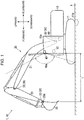
FIG. 1 is a side view of awork machine 10. -
FIG. 2 is a block diagram of a tipattachment discrimination device 1 provided in thework machine 10 shown inFIG. 1 . -
FIG. 3 is a flowchart of the tipattachment discrimination device 1 shown inFIG. 2 . -
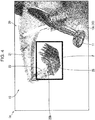
FIG. 4 is an image captured by acamera 40 shown inFIG. 1 . -
FIG. 5 is an image captured by thecamera 40 shown inFIG. 1 . -
FIG. 6 is a diagram corresponding toFIG. 1 showing atip attachment 25 shown inFIG. 1 in a dead angle for thecamera 40. - With reference to
FIGS. 1 to 6 , a tipattachment discrimination device 1 shown inFIG. 1 will be described. - The tip
attachment discrimination device 1 is a device that automatically discriminates a type of atip attachment 25, and is provided in awork machine 10. Thework machine 10 includes a construction machine that performs work such as construction work. As the construction machine, for example, thework machine 10 such as a hydraulic excavator, a hybrid shovel, a crane, or the like can be employed. Thework machine 10 includes alower travelling body 11, anupper slewing body 13, awork device 20, a workdevice posture sensor 30, and acamera 40. Furthermore, thework machine 10 includes amonitor 50 and acontroller 60 shown inFIG. 2 . Note that in the present specification, a front direction of theupper slewing body 13 is described as forward, a rear direction of theupper slewing body 13 is described as rearward, and forward and rearward are collectively described as a front-and -rear direction. When viewed forward from the rear, a left side is described as leftward, a right side is described as rightward, and the left side and the right side are collectively described as a right-and-left direction. A direction perpendicular to each of the front-and-rear direction and the right-and-left direction is described as an up-and-down direction. An upper side of the up-and-down direction is described as upward, and a lower side of the up-and-down direction is described as downward. - As shown in
FIG. 1 , thelower travelling body 11 includes, for example, a crawler, and causes thework machine 10 to travel. Abottom surface 11b of the lower travelling body 11 (bottom surface of the work machine 10) is in contact with the ground plane A. Theupper slewing body 13 is provided above thelower travelling body 11 and is configured to be pivotable about the up-and-down direction with respect to thelower travelling body 11. Theupper slewing body 13 includes acab 13c (driver's cab). - The
work device 20 is a device that is attached to theupper slewing body 13 and performs work. Thework device 20 includes aboom 21, anarm 23, and thetip attachment 25. Theboom 21 is rotatably attached to theupper slewing body 13. Thearm 23 is rotatably attached to theboom 21. - The
tip attachment 25 is provided at a tip of thework device 20. Thetip attachment 25 is replaceable with different types of tip attachments. The types of thetip attachments 25 include a bucket (example shown inFIG. 1 ), a clamshell, a scissor-shaped device, a hammer, a magnet, and the like. Thetip attachment 25 is rotatably attached to thearm 23. A position serving as a reference for thetip attachment 25 is referred to as areference position 25b. Thereference position 25b is a position determined regardless of the type of thetip attachment 25. Thereference position 25b is, for example, a proximal portion of thetip attachment 25, and is, for example, a rotational axis (bucket pin or the like) of thetip attachment 25 with respect to thearm 23. Note that inFIGS. 2 and3 , thetip attachment 25 is described as "tip ATT." Theboom 21, thearm 23, and thetip attachment 25 are driven by a boom cylinder (not shown), an arm cylinder (not shown), and an attachment cylinder (not shown), respectively. - The work
device posture sensor 30 is a sensor that detects a posture of thework device 20 shown inFIG. 1 . The workdevice posture sensor 30 includes aboom angle sensor 31, anarm angle sensor 33, and a tipattachment angle sensor 35. Theboom angle sensor 31 detects an angle of theboom 21 with respect to the upper slewing body 13 (boom 21 angle). Theboom angle sensor 31 includes, for example, an angle sensor such as an encoder provided in a proximal portion of theboom 21. - Here, the
boom angle sensor 31 may include, for example, a sensor that detects an expansion and contraction amount of the boom cylinder that drives theboom 21. In this case, theboom angle sensor 31 is required at least to convert the expansion and contraction amount of the boom cylinder into theboom 21 angle and output theboom 21 angle to thecontroller 60. Alternatively, theboom angle sensor 31 may output the detected expansion and contraction amount to thecontroller 60, and thecontroller 60 may convert the expansion and contraction amount into theboom 21 angle. The configuration of detecting the angle by detecting the expansion and contraction amount of the cylinder is also applicable to thearm angle sensor 33 and the tipattachment angle sensor 35. Thearm angle sensor 33 detects the angle of thearm 23 with respect to the boom 21 (arm 23 angle). The tipattachment angle sensor 35 detects the angle of thetip attachment 25 with respect to the arm 23 (tip attachment 25 angle). - The camera 40 (image capturing device) is configured to capture an image within a movable range of the
tip attachment 25. Thecamera 40 captures an image of thework device 20 and surroundings thereof. Thecamera 40 is preferably configured to capture the entire range assumed as the movable range of thetip attachment 25. Thecamera 40 may be attached to theupper slewing body 13, for example, may be attached to thecab 13c (for example, upper left front), and may be attached to, for example, a portion of theupper slewing body 13 other than thecab 13c. Thecamera 40 is fixed to theupper slewing body 13. Thecamera 40 may be configured to be movable (for example, pivotable) with respect to theupper slewing body 13. Thecamera 40 may include, for example, a monocular camera. In order to reduce the cost of thecamera 40, thecamera 40 is preferably a monocular camera. Thecamera 40 preferably has, for example, a zoom function such as an optical zoom function. Specifically, a zoom position (focal length) of thecamera 40 is preferably continuously variable between a telephoto side and a wide-angle side. Note thatFIG. 1 shows one example of an angle ofview 40a of thecamera 40. - The
monitor 50 displays various information items. Themonitor 50 may display an image captured by thecamera 40, for example, as shown inFIG. 4 . Themonitor 50 may display a detection frame F (seeFIG. 4 ). Details of the detection frame F will be described later. Themonitor 50 may display a discrimination result of the type of thetip attachment 25. - As shown in
FIG. 2 , the controller 60 (control unit) performs input-output of a signal (information), computation (determination, calculation), and the like. Thecontroller 60 includes a first controller 61 (main control unit) and a second controller 62 (auxiliary control unit). Thefirst controller 61 includes, for example, a computer including a processor such as a CPU and a memory such as a semiconductor memory, and controls an operation of the work machine 10 (seeFIG. 1 ). Thefirst controller 61 performs acquisition, processing, storage, and the like of information regarding thework machine 10. Thefirst controller 61 is connected to the workdevice posture sensor 30, thecamera 40, and themonitor 50. Thesecond controller 62 includes, for example, a computer including a processor such as a CPU and a memory such as a semiconductor memory, and discriminates (identifies) the type of thetip attachment 25 from image information including the tip attachment 25 (seeFIG. 4 ). Thesecond controller 62 is a recognition unit that executes image recognition by artificial intelligence (AI). Note that thefirst controller 61 and thesecond controller 62 may be integrated into one. At least either one of thefirst controller 61 and thesecond controller 62 may be subdivided. For example, thefirst controller 61 and thesecond controller 62 may be divided according to different types of function. - With reference to the flowchart shown in
FIG. 3 , the operation of the tip attachment discrimination device 1 (mainly operation of the controller 60) will be described. Note that in the following, each component of the tip attachment discrimination device 1 (camera 40,controller 60, and the like) will be mainly described with reference toFIG. 1 , and each step of the flowchart will be described with reference toFIG. 3 . - In step S11, the
camera 40 captures an image including thetip attachment 25. Here, thecamera 40 is required at least to capture an image including thetip attachment 25 successively in terms of time. Thecontroller 60 acquires the image captured by thecamera 40 as shown inFIG. 4 (hereinafter referred to as "camera image Im"). Examples of the camera image Im captured by thecamera 40 are shown inFIGS. 4 and5. FIG. 5 shows a remote state in which thetip attachment 25 has become more distant from thecamera 40 than in a close state shown inFIG. 4 . Note that inFIGS. 4 and5 , illustration of portions other than thework machine 10 is omitted. - In step S13, the work
device posture sensor 30 detects the posture of thework device 20.
In more detail, theboom angle sensor 31 detects theboom 21 angle, thearm angle sensor 33 detects thearm 23 angle, and the tipattachment angle sensor 35 detects thetip attachment 25 angle.
Then, thefirst controller 61 of thecontroller 60 acquires posture information on thework device 20 detected by the workdevice posture sensor 30. Thefirst controller 61 calculates a relative position of thereference position 25b with respect to theupper slewing body 13 based on theboom 21 angle and thearm 23 angle. Thefirst controller 61 can calculate the rough position of thetip attachment 25 based on the position of thereference position 25b and thetip attachment 25 angle. Details of this calculation will be described later. - In step S20, the
first controller 61 sets the detection frame F in the camera image Im as shown inFIG. 4 . The detection frame F is a frame within the camera image Im captured by the camera 40 (seeFIG. 1 ), and is a frame set in an area including thetip attachment 25. The image inside the detection frame F is used for discriminating the type of thetip attachment 25. The image outside the detection frame F is not used for discriminating the type of thetip attachment 25. - The position, size, shape, and the like of the detection frame F in the camera image Im are set as follows. The detection frame F is set such that the entire external shape of the
tip attachment 25 is included inside the detection frame F. - A background portion outside the external shape of the
tip attachment 25 in the camera image Im is unnecessary information, that is, noise when discriminating thetip attachment 25. Therefore, the detection frame F is preferably set so as to minimize the background portion within the detection frame F. That is, the detection frame F is preferably set at a size as small as possible and such that the entire external shape of thetip attachment 25 fits inside the detection frame F. For example, thetip attachment 25 preferably appears in the central portion within the detection frame F. - The position and size of the
tip attachment 25 appearing in the camera image Im change depending on the posture of thework device 20. For example, as shown inFIG. 5 , as thetip attachment 25 is more distant from thecamera 40, thetip attachment 25 appears smaller in the camera image Im. For example, as thetip attachment 25 is at a higher position, thetip attachment 25 appears at an upper position in the camera image Im. For example, an aspect ratio of thetip attachment 25 in the camera image Im changes depending on the angle of thetip attachment 25 with respect to thearm 23. - Therefore, the detection frame F is set based on the posture of the
work device 20. For example, the detection frame F is set based on the position of thereference position 25b in the camera image Im. For example, the position of thereference position 25b in the camera image Im is calculated based on theboom 21 angle and thearm 23 angle. For example, the position of thereference position 25b in the camera image Im is acquired based on the position of thereference position 25b with respect to theupper slewing body 13 or thecamera 40 shown inFIG. 1 , which is determined based on theboom 21 angle and thearm 23 angle. Also, the detection frame F is set based on thetip attachment 25 angle. - Specifically, the
reference position 25b is calculated as follows, for example. Thefirst controller 61 reads, from a memory (not shown), a reference position determination table in which correspondence between theboom 21 angle, thearm 23 angle, and thereference position 25b in the camera image Im is determined in advance. Then, thefirst controller 61 is required at least to acquire thereference position 25b by identifying thereference position 25b corresponding to theboom 31 angle detected by theboom angle sensor 31 and thearm 23 angle detected by thearm angle sensor 33 from the reference position determination table. - Here, the reference position determination table is created in advance, for example, by a simulation using the specified
work machine 10. By this simulation, thecamera 40 captures thework device 20 while changing each of theboom 21 angle and thearm 23 angle. Then, the position of thereference position 25b is identified in each of the obtained camera images Im, and a plurality of data sets in which thereference position 25b is associated with theboom 21 angle and thearm 23 angle is generated and stored in the position determination table. As described above, the position determination table is created. Note that this work may be performed by a person or by image processing. - Also, the detection frame F is set in the camera image Im as described below. The
first controller 61 reads, from a memory (not shown), a detection frame determination table in which correspondence between theboom 21 angle, thearm 23 angle, thetip attachment 25 angle, and detection frame information indicating the size of the detection frame F is determined in advance. Here, the detection frame information includes, for example, the length of the vertical side and the length of the horizontal side of the detection frame F, positioning information indicating a position where thereference position 25b is to be positioned within the detection frame F, and other information. Then, thefirst controller 61 identifies, from the detection frame determination table, the detection frame information corresponding to theboom 21 angle detected by theboom angle sensor 31, thearm 23 angle detected by thearm angle sensor 33, and thetip attachment 25 angle detected by the tipattachment angle sensor 35. Then, thefirst controller 61 is required at least to set the detection frame F indicated by the identified detection frame information in the camera image Im. At this time, thefirst controller 61 is required at least to set the detection frame F such that thereference position 25b is positioned at a position within the detection frame F indicated by the positioning information included in the detection frame information. - Here, the detection frame determination table is created in advance, for example, by a simulation using the specified
work machine 10 to which the specifiedtip attachment 25 such as a bucket is attached. By this simulation, thecamera 40 captures thework device 20 while changing each of theboom 21 angle, thearm 23 angle, and thetip attachment 25 angle. Then, a certain area including thetip attachment 25 is extracted from each of the obtained camera images Im, and the extracted area is set as the detection frame F. Here, as the detection frame F, for example, a quadrilateral area circumscribing thetip attachment 25 in the camera image Im may be employed, or a quadrilateral area slightly larger in size than the circumscribing quadrilateral may be employed. This work may be performed by a person or by image processing. - In this way, the
first controller 61 sets the detection frame F based on the posture of thework device 20. Therefore, thefirst controller 61 does not need to use an object detection algorithm, which is a process for detecting thetip attachment 25, in the entire area of the camera image Im. Therefore, a calculation load of thefirst controller 61 can be reduced accordingly. Moreover, since it is not necessary to use the object detection algorithm in the entire area of the camera image Im, the detection position of thetip attachment 25 that is subject to type discrimination is not erroneously recognized. For example, it is assumed that atip attachment 25 different from thetip attachment 25 attached to thearm 23 is positioned within the angle of view of thecamera 40 and appears in the camera image Im. In this case, theother tip attachment 25, which is not attached to thework machine 10, is not subject to type discrimination. Also, in this case, theother tip attachment 25, which is positioned away from thereference position 25b, appears outside the detection frame F in the camera image Im. Therefore, the present embodiment can prevent theother tip attachment 25 from becoming subject to type discrimination. - The position and size of the
tip attachment 25 appearing in the camera image Im change depending on the structure of thework machine 10. For example, the position, size, and the like of thetip attachment 25 in the camera image Im change depending on the length of theboom 21 and the length of thearm 23. Moreover, for example, the type of thetip attachment 25 that is assumed to be provided in thework device 20 changes depending on the size of the work machine 10 (for example, "XX ton class"). Then, the position, size, and the like of thetip attachment 25 in the camera image Im change. - Therefore, the detection frame F is preferably set based not only on a detection value of the work
device posture sensor 30 but also on structure information indicating the structure of thework machine 10. The structure information is included in, for example, main specifications of thework machine 10. The structure information may be, for example, set (stored) in advance by thefirst controller 61, or may be acquired by some kind of method. The structure information includes, for example, information on theupper slewing body 13, information on theboom 21, and information on thearm 23. The structure information includes, for example, the size (dimension) and relative position of each of theupper slewing body 13, theboom 21, and thearm 23. The structure information includes the position of thecamera 40 with respect to theupper slewing body 13. Thecontroller 60 can calculate the posture of thework device 20 more accurately by using not only the detection value of the workdevice posture sensor 30 but also the structure information on thework machine 10. For example, thecontroller 60 can calculate thereference position 25b more accurately. As a result, the background portion within the detection frame F can be reduced, and the accuracy of type discrimination of thetip attachment 25 can be improved. - When setting the detection frame F by using the structure information on the
work machine 10, thefirst controller 61 can perform processing as in the following [Example A1] or [Example A2]. - [Example A1] First, the rough detection frame F is set based on the posture of the
work device 20 without using the structure information on thework machine 10. Thereafter, the detection frame F may be corrected based on the structure information on thework machine 10. - Specifically, the
first controller 61 first determines the size of the detection frame F with reference to the detection frame determination table described above. Next, thefirst controller 61 is required at least to correct the size of the detection frame F by calculating a ratio of weight information on the specifiedwork machine 10 used when creating the detection frame determination table to weight information included in the structure information on thework machine 10, and multiplying the size of the detection frame F identified from the detection frame determination table by the ratio. Note that the weight information is information indicating the size of thework machine 10, such as "XX ton class" described above. - [Example A2] The detection frame F may be set from the beginning based on the structure information on the
work machine 10 and the posture of thework device 20 without performing the correction as in [Example A1] described above. Note that the shape of the detection frame F is rectangular in the example shown inFIG. 4 , but may be a polygon, a circle, an ellipse, or a similar shape other than quadrilateral. - Specifically, the
first controller 61 calculates thereference position 25b in the three-dimensional coordinate system of thework machine 10 by using the length of theboom 21 and the length of thearm 23 included in the structure information, and theboom 21 angle detected by theboom angle sensor 31 and thearm 23 angle detected by thearm angle sensor 33. Then, thefirst controller 61 calculates thereference position 25b in the camera image Im by projecting thereference position 25b in the three-dimensional coordinate system onto a captured surface of thecamera 40. Then, thefirst controller 61 is required at least to set the detection frame F in the camera image Im by using the detection frame determination table described above. At this time, thecontroller 60 may correct the size of the detection frame F as shown in Example A1. - Note that even without the structure information on the
work machine 10, the structure of thework machine 10 is roughly determined and is limited to a certain range. Therefore, even when thecontroller 60 does not acquire the structure information on thework machine 10, thecontroller 60 can set the detection frame F to include thetip attachment 25. - The
first controller 61 sequentially changes the setting of the detection frame F according to the change in the posture of thework device 20. Specifically, for example, the detection frame F is changed as follows. When the position of thereference position 25b in the camera image Im changes, thefirst controller 61 changes the position of the detection frame F according to the changed position of thereference position 25b. When thereference position 25b moves away from thecamera 40 and thetip attachment 25 appearing in the camera image Im becomes smaller, thefirst controller 61 makes the detection frame F smaller. Similarly, when thereference position 25b comes closer to thecamera 40 and thetip attachment 25 appearing in the camera image Im becomes larger, thecontroller 60 makes the detection frame F larger. When the angle of thetip attachment 25 with respect to thearm 23 changes and it is assumed that the aspect ratio of thetip attachment 25 appearing in the camera image Im changes, thefirst controller 61 changes the aspect ratio of the detection frame F. Note that in the detection frame determination table described above, a quadrilateral area circumscribing thetip attachment 25 appearing in the camera image Im or a quadrilateral area slightly larger in size than the circumscribing quadrilateral is set as the detection frame F. Therefore, if the detection frame F is set using the detection frame determination table, the size of the detection frame F is set smaller as thereference position 25b moves away from thecamera 40, and the size of the detection frame F is set larger as thereference position 25b comes closer to thecamera 40. - In step S31, the
first controller 61 determines whether the position of thetip attachment 25 is a position that can be in a dead angle for thecamera 40 as shown inFIG. 6 . For example, during excavation work of thework machine 10 or the like, thetip attachment 25 may be in a dead angle for thecamera 40. In order to make this determination, thefirst controller 61 stores information in which a predetermined posture condition is set in advance in a memory. The predetermined posture condition is a condition of the posture of thework device 20 and a condition in which the position of thetip attachment 25 can be in a dead angle for thecamera 40. Specifically, this is a condition in which at least part of thetip attachment 25 can be disposed on the Z2 side opposite to the Z1 side where thecamera 40 is disposed with respect to the ground plane A of thework machine 10. The ground plane A is a virtual plane parallel to thebottom surface 11b and including thebottom surface 11b. When the ground plane A is a horizontal plane, the "Z2 side" is a lower side of the ground plane A. - At the time of step S31, the type of the
tip attachment 25 is unknown, and the structure (dimension, shape, and the like) of thetip attachment 25 is unknown. Therefore, even if the posture of thework device 20 is known, it is unknown whether thetip attachment 25 is actually disposed on the Z2 side of the ground plane A. Therefore, for example, the predetermined posture condition may be the posture of thework device 20 in which thelargest tip attachment 25 among thetip attachments 25 assumed to be provided in thework device 20 is disposed on the Z2 side of the ground plane A. For example, the predetermined posture condition may be set based on the distance from the ground plane A to thereference position 25b. - Specifically, on the assumption that the assumed
largest tip attachment 25 has been attached, thefirst controller 61 determines the position of the tip of thetip attachment 25 from theboom 21 angle, thearm 23 angle, and thetip attachment 25 angle respectively detected by theboom angle sensor 31, thearm angle sensor 33, and the tipattachment angle sensor 35. Then, when the distance in the up-and-down direction between the position of the tip of thetip attachment 25 and thereference position 25b is longer than the distance in the up-and-down direction from thereference position 25b to the ground plane A, thefirst controller 61 may determine that the predetermined posture condition is satisfied. - As shown in
FIG. 1 , when the posture of thework device 20 detected by the workdevice posture sensor 30 does not satisfy the predetermined posture condition (NO in step S31), the process proceeds to step S33 in order to perform type discrimination of thetip attachment 25. As shown inFIG. 6 , when the posture of thework device 20 satisfies the predetermined posture condition (YES in S31), thefirst controller 61 does not perform type discrimination of thetip attachment 25. In this case, the current flow is finished, and the process returns to, for example, "start." In this manner, when thetip attachment 25 is disposed at a position that can be in a dead angle for thecamera 40, type discrimination of thetip attachment 25 is not performed. Therefore, erroneous discrimination can be eliminated, and unnecessary processing can be eliminated. - Note that in the flowchart shown in
FIG. 3 , after the image information of thecamera 40 shown inFIG. 1 is acquired (S11), the posture information on thework device 20 is acquired (S13), and the determination in step S31 is performed. However, this is one example, and in the present invention, in a state where the image information of thecamera 40 has not been acquired, that is, in a state where the processing of S11 has not been performed, the posture information on thework device 20 may be acquired (S13), and the determination of step S31 may be performed. The same is true of the determinations in steps S33 and S35. This is because the processing of steps S31, S33, and S35 does not need the camera image Im. When the posture of thework device 20 satisfies the predetermined posture condition (YES in step S31), the current flow may be finished. The same is true of NO in step S33. In this case, in a case where the type discrimination of thetip attachment 25 is not performed, thefirst controller 61 can omit the processing of step S11 for acquiring the image information of thecamera 40. Note that in this case, it is only required that the processing of step S11 is provided between steps S35 and S37. - In step S33, the
first controller 61 determines a corresponding distance L corresponding to the distance from thecamera 40 to thetip attachment 25. When the corresponding distance L is too long, in the camera image Im shown inFIG. 5 , thetip attachment 25 may appear small, an image of a portion of thetip attachment 25 may be unclear even if enlarged, and the accuracy of type discrimination of thetip attachment 25 may not be secured. Therefore, it is determined whether the corresponding distance L shown inFIG. 1 is short enough to secure the accuracy of discrimination. In more detail, thefirst controller 61 acquires the corresponding distance L corresponding to the distance from thetip attachment 25 to thecamera 40 based on the posture of thework device 20 detected by the workdevice posture sensor 30. - At the time of step S33, the type of the
tip attachment 25 is unknown, and the structure of thetip attachment 25 is unknown. Therefore, the actual distance from thecamera 40 to thetip attachment 25 is unknown. Therefore, in the determination of step S33, the corresponding distance L corresponding to the actual distance from thecamera 40 to thetip attachment 25 is used. For example, the corresponding distance L is a distance in the front-and-rear direction from thecamera 40 to thereference position 25b. The same is true of step S35. Alternatively, the corresponding distance L may be, for example, a distance in the front-and-rear direction between thecamera 40 and thelargest tip attachment 25 among thetip attachments 25 assumed to be provided in thework device 20. The same is true of step S35. - When the corresponding distance L is equal to or shorter than a first predetermined distance determined in advance (YES in step S33), the process proceeds to step S35 in order to perform type discrimination of the
tip attachment 25. A value of the first predetermined distance is set in thefirst controller 61 in advance. The first predetermined distance is set according to whether the accuracy of discriminating thetip attachment 25 can be secured. For example, the first predetermined distance is set according to the performance of thecamera 40, discriminating capability of thesecond controller 62, and the like. The same is true of a second predetermined distance used in step S35. Note that, for example, when a zoom function of thecamera 40 is used, it is only required that the accuracy of discrimination of thetip attachment 25 can be secured with the zoom position being on the most telephoto side. The first predetermined distance is 5 m in the example shown inFIG. 3 , but can be set in various manners. - When the corresponding distance L is longer than the first predetermined distance (NO in step S33), the
first controller 61 does not perform type discrimination of thetip attachment 25. In this case, the current flow is finished, and the process returns to, for example, "start." In this way, when the corresponding distance L corresponding to the distance from thecamera 40 to thetip attachment 25 is long and there is a possibility that the accuracy of type discrimination of thetip attachment 25 may not be secured, type discrimination of thetip attachment 25 is not performed. Therefore, erroneous discrimination can be eliminated, and unnecessary processing can be eliminated, - In step S35, the
first controller 61 determines whether to set the zoom position of thecamera 40 at a position on the telephoto side from the most wide-angle side based on the corresponding distance L. When the corresponding distance L is equal to or longer than the second predetermined distance (YES step S35), the process proceeds to step S37. A value of the second predetermined distance is set by thecontroller 60 in advance. The second predetermined distance is shorter than the first predetermined distance. The second predetermined distance is 3 m in the example shown inFIG. 3 , but can be set in various manners. When the corresponding distance L is shorter than the second predetermined distance (NO in step S35), the zoom position of thecamera 40 is set on the most wide-angle side, and the process proceeds to step S40. Note that it is possible to set the corresponding distance L at various distances. For example, the corresponding distance L used in the determination of step S33 and the corresponding distance L used in the determination of step S35 may be the same or different from each other. - In step S37, the
first controller 61 sets the zoom position of thecamera 40 at a position on the telephoto side from the most wide-angle side. As the corresponding distance L increases, the zoom position of thecamera 40 is set on the telephoto side more, and the image including the detection frame F is enlarged. This control is performed when the corresponding distance L is equal to or shorter than a first predetermined value (YES in S33) (for example, 5 m or shorter) and equal to or longer than a second predetermined value (YES in S35) (for example, 3 m or longer). By setting the zoom position of thecamera 40 on the telephoto side, the image of thetip attachment 25 becomes clearer than when the image of thetip attachment 25 is enlarged as it is and magnified, and the accuracy of type discrimination of thetip attachment 25 can be improved. - Note that when the zoom position of the
camera 40 is set on the telephoto side in step S37, thefirst controller 61 is required at least to change the size of the detection frame F according to a telephoto ratio. In this case, thefirst controller 61 is required at least to read, from a memory, a table in which correspondence between the telephoto ratio and an enlargement ratio of the detection frame F according to the telephoto ratio is defined in advance, refer to the table to identify the enlargement ratio of the detection frame F according to the telephoto ratio, and enlarge the detection frame F that is set in step S20 by the identified enlargement ratio. In this table, for example, the enlargement ratio of the detection frame F is stored in the camera image Im captured by telephotography such that the size of the detection frame F is enlarged to a size that includes the entire area of the image of the tip attachment. - In step S40, the
second controller 62 of thecontroller 60 discriminates the type of thetip attachment 25. This discrimination is performed based on the image of thetip attachment 25 within the detection frame F. The discrimination is performed by comparing a feature amount of thetip attachment 25 acquired from the image of thetip attachment 25 within the detection frame F with a feature amount that is set in advance by thesecond controller 62. The feature amount used for the discrimination is, for example, a contour shape (external shape) of thetip attachment 25. - In more detail, the
first controller 61 shown inFIG. 2 cuts out the image within the detection frame F (seeFIG. 4 ) from the camera image Im under arbitrary conditions and timing. That is, thefirst controller 61 eliminates an area other than the detection frame F from the camera image Im. The number of images to be cut out within the detection frame F may be one, or may be two or more. Specifically, thefirst controller 61 may cut out a plurality of detection frames F by cutting out the detection frame F from each of the plurality of camera images Im successive on a time-series basis. - The
first controller 61 outputs the cut out images to thesecond controller 62. In a memory of thesecond controller 62, a feature amount of a reference image serving as a reference for type discrimination of thetip attachment 25 is stored in advance in association with a type name of thetip attachment 25. The reference image includes images of various postures of various types oftip attachments 25. Thesecond controller 62 acquires the image within the detection frame F input from thefirst controller 61 as an input image, and calculates the feature amount from the input image. Here, as the feature amount, for example, a contour shape of the image within the detection frame F can be employed. Thesecond controller 62 is required at least to extract the contour shape of the image within the detection frame F by applying, for example, a predetermined edge detection filter to the acquired input image, and calculate the contour shape as the feature amount. - Then, the
second controller 62 discriminates the type of thetip attachment 25 by comparing the feature amount of the input image with the feature amount of the reference image. As tendencies of the feature amount of the input image and the feature amount of the reference image match more, the accuracy of type discrimination of thetip attachment 25 increases. Moreover, as the number of reference images increases and an amount of learning increases, the accuracy of type discrimination of thetip attachment 25 increases. Then, thesecond controller 62 outputs a discrimination result to thefirst controller 61. - Specifically, the
second controller 62 is required at least to identify the feature amount of the reference image having the highest similarity to the feature amount of the input image among the feature amounts of the reference image stored in the memory, and output the type name of thetip attachment 25 associated with the identified feature amount of the reference image to thefirst controller 61 as the discrimination result. - The feature amount of the reference image is generated in advance by performing machine learning on a plurality of images of the
tip attachment 25 having different postures for each of different types. As the machine learning, for example, a neural network, clustering, Bayesian network, support vector machine, and the like can be employed. As the feature amount, in addition to the outline shape, for example, the Haar-LIKE feature amount, pixel difference feature amount, edge of histogram (EOH) feature amount, histogram of oriented gradients (HOG) feature amount, and the like can be employed. - Alternatively, the
second controller 62 stores, in a memory, a neural network obtained by performing machine learning on a plurality of images of thetip attachment 25 using the type name of thetip attachment 25 as a teacher signal. Then, thesecond controller 62 may input the input image acquired from thefirst controller 61 into the neural network, and output the type name of thetip attachment 25 output from the neural network as the discrimination result to thefirst controller 61. - Note that when a mode is employed in which a plurality of images of the detection frame F is input from the
first controller 61, thesecond controller 62 is required at least to compare each of the feature amounts of the plurality of images of the detection frame F with each of the feature amounts of the plurality of reference images stored in a memory to determine the type of thetip attachment 25 by majority decision. That is, thesecond controller 62 is required at least to determine the type of thetip attachment 25 most often discriminated in the discrimination result for each of the plurality of images of the detection frame F as the final type of thetip attachment 25. - Here, a capturing angle of the
camera 40 with respect to thetip attachment 25 is limited more when thecamera 40 shown inFIG. 1 is fixed to theupper slewing body 13 than when thecamera 40 is not fixed to theupper slewing body 13. Therefore, when thecamera 40 is fixed to theupper slewing body 13, the reference image required for type discrimination of thetip attachment 25 can be reduced. This facilitates collection of the reference image. - In step S50, the
first controller 61 outputs the discrimination result input from thesecond controller 62 to themonitor 50. In this case, thefirst controller 61 may output the discrimination result to themonitor 50 by outputting a display command for displaying the discrimination result to themonitor 50. Here, themonitor 50 may display, for example, a character string indicating the type name of thetip attachment 25, an icon that graphically indicates the type of thetip attachment 25, or both the character string and the icon. - Note that the discrimination result may be used for interference prevention control of the
work machine 10. Specifically, thefirst controller 61 determines the tip position of thetip attachment 25 by using the discrimination result of thetip attachment 25, theboom 21 angle, thearm 23 angle, and thetip attachment 25 angle. Then, when thefirst controller 61 determines that the tip position is positioned in an interference prevention area that is set around thework machine 10, thefirst controller 61 is required at least to execute interference prevention control such as reducing the operation speed of thework device 20 or stopping the operation of thework device 20. - An examination is performed into a case where type discrimination of the
tip attachment 25 shown inFIG. 1 is performed based on the distance distribution (distance image, depth distribution) detected by the distance sensor. In this case, there is a problem that the distance sensor has a higher cost than the monocular camera. Also, there is a problem that the distance sensor is more affected by dust than the monocular camera. Meanwhile, in the present embodiment, the monocular camera can be used as thecamera 40. When thecamera 40 is the monocular camera, these problems can be eliminated. - Furthermore, the distance sensor such as a time of flight (TOF) sensor has a narrow angle of view, and thus has a more limited detection range than the monocular camera. Therefore, it is considered to measure the distance distribution around the
tip attachment 25 by using the distance sensor, for example, with thework device 20 in a specified limited posture, such as a posture in which thetip attachment 25 is in contact with the ground. However, in this case, when discriminating the type of thetip attachment 25, it is necessary to set thework device 20 in the specified posture, taking much time. Meanwhile, in the present embodiment, when discriminating the type of thetip attachment 25, the posture of thework device 20 can be set in almost any posture. Therefore, in the present embodiment, the degree of freedom of posture of thework device 20 when discriminating the type of thetip attachment 25 is high. In more detail, in the present embodiment, except for a state where type discrimination of thetip attachment 25 is not performed as in a case of YES in S31 and NO in S33 ofFIG. 3 , type discrimination of thetip attachment 25 can be performed with thework device 20 in any posture. Note that the condition under which type discrimination of thetip attachment 25 is not performed can be set in various manners. - Advantageous effects of the tip
attachment discrimination device 1 shown inFIG. 1 are as follows. - The tip
attachment discrimination device 1 includes thework device 20, thecamera 40, the workdevice posture sensor 30, and thecontroller 60. Thework device 20 is attached to theupper slewing body 13 of thework machine 10. Thework device 20 includes a tip (tip of the work device 20) including a plurality of types oftip attachment 25 in a replaceable manner. Thecamera 40 is attached to theupper slewing body 13 and can capture an image within a movable range of thetip attachment 25. The workdevice posture sensor 30 detects the posture of thework device 20. - [Configuration 1-1] The
controller 60 sets the detection frame F (seeFIG. 4 ) in an area including thetip attachment 25 with respect to the image captured by thecamera 40 based on the posture of thework device 20 detected by the workdevice posture sensor 30. Hereinafter,FIG. 4 is referred to for the detection frame F. - [Configuration 1-2] The
controller 60 discriminates the type of thetip attachment 25 based on the image of thetip attachment 25 within the detection frame F. - In the above-described [Configuration 1-2], the
controller 60 performs type discrimination of thetip attachment 25 based on the image. Therefore, thecontroller 60 can discriminate the type of thetip attachment 25 without using the distance distribution. As a result, the cost of thecamera 40 can be reduced more than when thecamera 40 needs to acquire the distance distribution. - Meanwhile, it can be said that there is less information for discrimination by distance information when type discrimination of the
tip attachment 25 is performed based on the image than when type discrimination is performed using the distance distribution. Therefore, even if there is little information for discrimination, it is important to secure the accuracy of type discrimination of thetip attachment 25. Here, the appearance of thetip attachment 25 in the camera image Im (for example, position, size, shape, and the like) changes depending on the posture of thework device 20. - Therefore, in the above-described [Configuration 1-1], the
controller 60 sets the detection frame F including thetip attachment 25 based on the posture of thework device 20. Therefore, thecontroller 60 can set the detection frame F suitable for type discrimination of thetip attachment 25. For example, thecontroller 60 can set the detection frame F such that theentire tip attachment 25 is included and the background portion around thetip attachment 25 is minimized. Therefore, it is possible to make the accuracy of type discrimination of thetip attachment 25 better than when the detection frame F is not set based on the posture of thework device 20. Therefore, the tipattachment discrimination device 1 can accurately perform type discrimination of thetip attachment 25 even without using the distance distribution. - [Configuration 2] The
camera 40 is fixed to theupper slewing body 13. - With the above-described [Configuration 2], the capturing angle of the
camera 40 with respect to thetip attachment 25 is limited more than when thecamera 40 is not fixed to theupper slewing body 13. Therefore, an amount of information required for type discrimination of thetip attachment 25 can be reduced. - [Configuration 3] The
controller 60 sequentially changes the setting of the detection frame F according to a change in the posture of thework device 20 detected by the workdevice posture sensor 30. - With the above-described [Configuration 3], after the detection frame F is set, even if the posture of the
work device 20 changes, thecontroller 60 can perform type discrimination of thetip attachment 25. - [Configuration 4] The
controller 60 sets the detection frame F based on the structure information on thework machine 10. - With the above-described [Configuration 1-1] and [Configuration 4], the
controller 60 sets the detection frame F based on the posture of thework device 20 detected by the workdevice posture sensor 30 and the structure information on thework machine 10. Therefore, thecontroller 60 can set the detection frame F more suitable for type discrimination of thetip attachment 25 than when the detection frame F is set based only on the posture of thework device 20. - [Configuration 5] The
camera 40 has a zoom function. Thecontroller 60 calculates the distance from thetip attachment 25 to thecamera 40 based on the posture of thework device 20 detected by the workdevice posture sensor 30, and sets the zoom position of thecamera 40 on the telephoto side as the distance increases. - With the above-described [Configuration 5], even if the distance from the
tip attachment 25 to thecamera 40 becomes longer, by setting the zoom position of thecamera 40 on the telephoto side, the resolution of the image of thetip attachment 25 within the detection frame F can be increased. Therefore, the accuracy of type discrimination of thetip attachment 25 can be improved. - As shown in
FIG. 6 , the predetermined posture condition is set in advance in thecontroller 60. The predetermined posture condition is a condition of the posture of thework device 20, and is a condition in which thetip attachment 25 can be disposed on the Z2 side opposite to the Z1 side on which thework machine 10 is disposed with respect to the ground plane A of thework machine 10. - [Configuration 6-1] When the posture of the
work device 20 detected by the workdevice posture sensor 30 does not satisfy the predetermined posture condition (NO in step S31 ofFIG. 3 ), thecontroller 60 performs type discrimination of thetip attachment 25 shown inFIG. 6 . - [Configuration 6-2] When the posture of the
work device 20 detected by the workdevice posture sensor 30 satisfies the predetermined posture condition (YES in step S31 ofFIG. 3 ), thecontroller 60 does not perform type discrimination of thetip attachment 25 shown inFIG. 6 . - When the
tip attachment 25 can be disposed on the Z2 side with respect to the ground plane A, at least part of thetip attachment 25 may be in a dead angle for thecamera 40. Then, type discrimination of thetip attachment 25 cannot be performed or the accuracy of discrimination cannot be secured in some cases. Therefore, the tipattachment discrimination device 1 has the above-described [Configuration 6-2]. Therefore, it is possible to inhibit thecontroller 60 from erroneously discriminating the type of thetip attachment 25, and to eliminate unnecessary processing of thecontroller 60. Also, the above-described [Configuration 6-2] makes it possible to perform type discrimination of thetip attachment 25 in a state where it is easy to secure the accuracy of type discrimination of thetip attachment 25. As a result, the accuracy of type discrimination of thetip attachment 25 can be improved. - The
controller 60 acquires the corresponding distance L corresponding to the distance from thetip attachment 25 to thecamera 40 based on the posture of thework device 20 detected by the workdevice posture sensor 30. - [Configuration 7-1] When the corresponding distance L is equal to or shorter than the first predetermined distance determined in advance (predetermined distance) (when YES in step S33 of
FIG. 3 ), thecontroller 60 performs type discrimination of thetip attachment 25 shown inFIG. 1 . - [Configuration 7-2] When the corresponding distance L is longer than the first predetermined distance (when NO in step S33 of
FIG. 3 ), thecontroller 60 does not perform type discrimination of thetip attachment 25 shown inFIG. 1 . - There is a possibility that, as the corresponding distance L increases and the distance from the
camera 40 to thetip attachment 25 increases, in the camera image Im (seeFIG. 4 ), thetip attachment 25 appears smaller, and it becomes more difficult to secure the accuracy of type discrimination of thetip attachment 25. Therefore, the tipattachment discrimination device 1 has the above-described [Configuration 7-2]. Therefore, it is possible to inhibit thecontroller 60 from erroneously discriminating the type of thetip attachment 25, and to eliminate unnecessary processing of thecontroller 60. Also, the above-described [Configuration 7-1] enables type discrimination of thetip attachment 25 in a state where it is easy to perform discrimination while the accuracy of type discrimination of thetip attachment 25 is secured. As a result, the accuracy of type discrimination of thetip attachment 25 can be improved. - The above-described embodiment may be modified in various manners. For example, connections between blocks in the block diagram shown in
FIG. 2 may be changed. For example, order of steps in the flowchart shown inFIG. 3 may be changed. For example, the number of components of the tipattachment discrimination device 1 shown inFIGS. 1 and2 may be changed, and some of the components may not be provided. - Some components of the tip
attachment discrimination device 1 may be provided outside thework machine 10. For example, thesecond controller 62 shown inFIG. 2 may be provided outside thework machine 10. For example, themonitor 50 may not be provided.
Claims (7)
- A tip attachment discrimination device of a work machine including: a lower travelling body; an upper slewing body provided above the lower travelling body; and a work device including a tip to which one of different types of tip attachments is attached in a replaceable manner, the work device being attached to the upper slewing body, the tip attachment discrimination device comprising:a camera attached to the upper slewing body and configured to capture an image within a movable range of the tip attachment;a work device posture sensor configured to detect a posture of the work device; anda controller,wherein the controller:sets a detection frame in an area including the tip attachment with respect to the image captured by the camera based on the posture of the work device detected by the work device posture sensor; anddiscriminates the type of the tip attachment based on the image of the tip attachment within the detection frame.
- The tip attachment discrimination device according to claim 1, wherein the camera is fixed to the upper slewing body.
- The tip attachment discrimination device according to claim 1 or 2, wherein the controller sequentially changes a setting of the detection frame according to a change in the posture of the work device detected by the work device posture sensor.
- The tip attachment discrimination device according to any one of claims I to 3, wherein the controller sets the detection frame based on structure information on the work machine.
- The tip attachment discrimination device according to any one of claims 1 to 4, wherein
the camera has a zoom function, and
the controller calculates a distance from the tip attachment to the camera based on the posture of the work device detected by the work device posture sensor, and sets a zoom position of the camera on a telephoto side as the distance increases. - The tip attachment discrimination device according to any one of claims 1 to 5, wherein
in the controller, a posture in which the tip attachment is disposed on a side opposite to a side on which the camera is disposed with respect to a ground plane of the work machine is set in advance as a predetermined posture condition, and
the controller:performs processing for discriminating the type of the tip attachment when the posture of the work device detected by the work device posture sensor does not satisfy the predetermined posture condition; anddoes not perform the processing for discriminating the type of the tip attachment when the posture of the work device detected by the work device posture sensor satisfies the predetermined posture condition. - The tip attachment discrimination device according to any one of claims 1 to 6, wherein the controller:acquires a corresponding distance corresponding to the distance from the tip attachment to the camera based on the posture of the work device detected by the work device posture sensor;performs the processing for discriminating the type of the tip attachment when the corresponding distance is equal to or shorter than a predetermined distance determined in advance; anddoes not perform the processing for discriminating the type of the tip attachment when the corresponding distance is longer than the predetermined distance.
Applications Claiming Priority (2)
| Application Number | Priority Date | Filing Date | Title |
|---|---|---|---|
| JP2018007324A JP7114907B2 (en) | 2018-01-19 | 2018-01-19 | Tip attachment discriminator |
| PCT/JP2018/044473 WO2019142523A1 (en) | 2018-01-19 | 2018-12-04 | Tip attachment discrimination device |
Publications (2)
| Publication Number | Publication Date |
|---|---|
| EP3723039A1 true EP3723039A1 (en) | 2020-10-14 |
| EP3723039A4 EP3723039A4 (en) | 2021-04-21 |
Family
ID=67301008
Family Applications (1)
| Application Number | Title | Priority Date | Filing Date |
|---|---|---|---|
| EP18900720.6A Withdrawn EP3723039A4 (en) | 2018-01-19 | 2018-12-04 | Tip attachment discrimination device |
Country Status (5)
| Country | Link |
|---|---|
| US (1) | US20200347579A1 (en) |
| EP (1) | EP3723039A4 (en) |
| JP (1) | JP7114907B2 (en) |
| CN (1) | CN111587448A (en) |
| WO (1) | WO2019142523A1 (en) |
Families Citing this family (2)
| Publication number | Priority date | Publication date | Assignee | Title |
|---|---|---|---|---|
| CA3030434C (en) * | 2016-07-15 | 2023-08-15 | Cqms Pty Ltd | A wear member monitoring system |
| KR20220102804A (en) * | 2021-01-14 | 2022-07-21 | 현대두산인프라코어(주) | System and method of controlling construction machinery |
Family Cites Families (14)
| Publication number | Priority date | Publication date | Assignee | Title |
|---|---|---|---|---|
| JP4578767B2 (en) | 2002-11-08 | 2010-11-10 | パナソニック株式会社 | Object recognition device and object recognition program |
| JP2008060988A (en) | 2006-08-31 | 2008-03-13 | Matsushita Electric Ind Co Ltd | Driving environment information acquisition device |
| US9437005B2 (en) * | 2011-07-08 | 2016-09-06 | Canon Kabushiki Kaisha | Information processing apparatus and information processing method |
| CN102642207B (en) * | 2012-04-12 | 2014-08-06 | 华北电力大学 | Multifunctional actuator for nuclear power plant operation and control method thereof |
| KR20150058232A (en) * | 2012-09-20 | 2015-05-28 | 볼보 컨스트럭션 이큅먼트 에이비 | Method for automatically recognizing and setting attachment and device therefor |
| US20160312432A1 (en) * | 2015-04-23 | 2016-10-27 | Caterpillar Inc. | Computer Vision Assisted Work Tool Recognition and Installation |
| WO2016047808A1 (en) * | 2015-09-30 | 2016-03-31 | 株式会社小松製作所 | Calibration system for imaging device, working machine, and calibration method for imaging device |
| KR101843382B1 (en) * | 2015-09-30 | 2018-03-29 | 가부시키가이샤 고마쓰 세이사쿠쇼 | Periphery monitoring device for crawler-type working machine |
| US10094093B2 (en) * | 2015-11-16 | 2018-10-09 | Caterpillar Inc. | Machine onboard activity and behavior classification |
| JP6681747B2 (en) * | 2016-03-02 | 2020-04-15 | 株式会社神戸製鋼所 | Attachment recognition device |
| JP2018005555A (en) | 2016-07-01 | 2018-01-11 | ソニー株式会社 | Image processing device, information processing device and method, as well as program |
| US10011976B1 (en) * | 2017-01-03 | 2018-07-03 | Caterpillar Inc. | System and method for work tool recognition |
| US10519631B2 (en) * | 2017-09-22 | 2019-12-31 | Caterpillar Inc. | Work tool vision system |
| KR20200105651A (en) * | 2018-01-10 | 2020-09-08 | 스미토모 겐키 가부시키가이샤 | Shovel and shovel management system |
-
2018
- 2018-01-19 JP JP2018007324A patent/JP7114907B2/en active Active
- 2018-12-04 US US16/962,118 patent/US20200347579A1/en not_active Abandoned
- 2018-12-04 EP EP18900720.6A patent/EP3723039A4/en not_active Withdrawn
- 2018-12-04 CN CN201880086353.4A patent/CN111587448A/en active Pending
- 2018-12-04 WO PCT/JP2018/044473 patent/WO2019142523A1/en not_active Ceased
Also Published As
| Publication number | Publication date |
|---|---|
| EP3723039A4 (en) | 2021-04-21 |
| JP7114907B2 (en) | 2022-08-09 |
| WO2019142523A1 (en) | 2019-07-25 |
| US20200347579A1 (en) | 2020-11-05 |
| JP2019125314A (en) | 2019-07-25 |
| CN111587448A (en) | 2020-08-25 |
Similar Documents
| Publication | Publication Date | Title |
|---|---|---|
| EP1981278B1 (en) | Automatic tracking device and automatic tracking method | |
| EP3690800B1 (en) | Information processing apparatus, information processing method, and program | |
| CN110926330B (en) | Image processing apparatus, image processing method, and program | |
| US20160364619A1 (en) | Vehicle-Surroundings Recognition Device | |
| CN114616591B (en) | Object tracking device and object tracking method | |
| US10970807B2 (en) | Information processing apparatus and storage medium | |
| JP2008097126A (en) | Moving object recognition apparatus, moving object recognition method, and computer program | |
| JP2003098424A (en) | Range finder based on image processing | |
| US10445872B2 (en) | Machine control measurements device | |
| WO2023025262A1 (en) | Excavator operation mode switching control method and apparatus and excavator | |
| CN110942520A (en) | Auxiliary positioning method, device, system and storage medium for working equipment | |
| US20200347579A1 (en) | Tip attachment discrimination device | |
| CN108713217A (en) | Remove countermeasure set | |
| CN118918365A (en) | Attitude generation method and device of engineering mechanical equipment, terminal equipment and storage medium | |
| JP7164172B2 (en) | PARKING FRAME CONSTRUCTION DEVICE AND PARKING FRAME CONSTRUCTION METHOD | |
| KR102741577B1 (en) | Operation record analysis system for construction machinery | |
| WO2021060136A1 (en) | System for detecting position of detection target object at periphery of working machine, and program for detecting position of detection target object at periphery of working machine | |
| JP5493705B2 (en) | Vehicle position detection device, vehicle position detection method, and vehicle position detection program | |
| CN110660134B (en) | Three-dimensional map construction method, three-dimensional map construction device and terminal equipment | |
| JPH07280517A (en) | Mobile object recognition device for automobiles | |
| JP2026048466A (en) | Control system, control method, and program | |
| JPH0973543A (en) | Image processing device | |
| KR20190139605A (en) | Gesture recognition device and method | |
| JP2002269570A (en) | Perimeter recognition device | |
| KR20250100870A (en) | SYSTEM AND METHOD FOR MATCHING LiDAR AND CAMERA |
Legal Events
| Date | Code | Title | Description |
|---|---|---|---|
| STAA | Information on the status of an ep patent application or granted ep patent |
Free format text: STATUS: THE INTERNATIONAL PUBLICATION HAS BEEN MADE |
|
| PUAI | Public reference made under article 153(3) epc to a published international application that has entered the european phase |
Free format text: ORIGINAL CODE: 0009012 |
|
| STAA | Information on the status of an ep patent application or granted ep patent |
Free format text: STATUS: REQUEST FOR EXAMINATION WAS MADE |
|
| 17P | Request for examination filed |
Effective date: 20200706 |
|
| AK | Designated contracting states |
Kind code of ref document: A1 Designated state(s): AL AT BE BG CH CY CZ DE DK EE ES FI FR GB GR HR HU IE IS IT LI LT LU LV MC MK MT NL NO PL PT RO RS SE SI SK SM TR |
|
| AX | Request for extension of the european patent |
Extension state: BA ME |
|
| A4 | Supplementary search report drawn up and despatched |
Effective date: 20210322 |
|
| RIC1 | Information provided on ipc code assigned before grant |
Ipc: E02F 9/28 20060101ALI20210316BHEP Ipc: E02F 9/26 20060101ALI20210316BHEP Ipc: G06T 7/00 20170101AFI20210316BHEP |
|
| DAV | Request for validation of the european patent (deleted) | ||
| DAX | Request for extension of the european patent (deleted) | ||
| STAA | Information on the status of an ep patent application or granted ep patent |
Free format text: STATUS: EXAMINATION IS IN PROGRESS |
|
| STAA | Information on the status of an ep patent application or granted ep patent |
Free format text: STATUS: THE APPLICATION HAS BEEN WITHDRAWN |
|
| 17Q | First examination report despatched |
Effective date: 20230929 |
|
| 18W | Application withdrawn |
Effective date: 20231012 |