EP3722852A1 - A support device for attaching an optical termination box to a wall mounting element - Google Patents
A support device for attaching an optical termination box to a wall mounting element Download PDFInfo
- Publication number
- EP3722852A1 EP3722852A1 EP20164961.3A EP20164961A EP3722852A1 EP 3722852 A1 EP3722852 A1 EP 3722852A1 EP 20164961 A EP20164961 A EP 20164961A EP 3722852 A1 EP3722852 A1 EP 3722852A1
- Authority
- EP
- European Patent Office
- Prior art keywords
- frame
- attachment members
- support device
- optical termination
- mounting element
- Prior art date
- Legal status (The legal status is an assumption and is not a legal conclusion. Google has not performed a legal analysis and makes no representation as to the accuracy of the status listed.)
- Granted
Links
Images




Classifications
-
- H—ELECTRICITY
- H02—GENERATION; CONVERSION OR DISTRIBUTION OF ELECTRIC POWER
- H02G—INSTALLATION OF ELECTRIC CABLES OR LINES, OR OF COMBINED OPTICAL AND ELECTRIC CABLES OR LINES
- H02G3/00—Installations of electric cables or lines or protective tubing therefor in or on buildings, equivalent structures or vehicles
- H02G3/02—Details
- H02G3/08—Distribution boxes; Connection or junction boxes
- H02G3/14—Fastening of cover or lid to box
-
- H—ELECTRICITY
- H02—GENERATION; CONVERSION OR DISTRIBUTION OF ELECTRIC POWER
- H02G—INSTALLATION OF ELECTRIC CABLES OR LINES, OR OF COMBINED OPTICAL AND ELECTRIC CABLES OR LINES
- H02G3/00—Installations of electric cables or lines or protective tubing therefor in or on buildings, equivalent structures or vehicles
- H02G3/02—Details
- H02G3/08—Distribution boxes; Connection or junction boxes
-
- H—ELECTRICITY
- H02—GENERATION; CONVERSION OR DISTRIBUTION OF ELECTRIC POWER
- H02G—INSTALLATION OF ELECTRIC CABLES OR LINES, OR OF COMBINED OPTICAL AND ELECTRIC CABLES OR LINES
- H02G3/00—Installations of electric cables or lines or protective tubing therefor in or on buildings, equivalent structures or vehicles
- H02G3/02—Details
- H02G3/08—Distribution boxes; Connection or junction boxes
- H02G3/12—Distribution boxes; Connection or junction boxes for flush mounting
-
- G—PHYSICS
- G02—OPTICS
- G02B—OPTICAL ELEMENTS, SYSTEMS OR APPARATUS
- G02B6/00—Light guides; Structural details of arrangements comprising light guides and other optical elements, e.g. couplings
- G02B6/44—Mechanical structures for providing tensile strength and external protection for fibres, e.g. optical transmission cables
- G02B6/4439—Auxiliary devices
- G02B6/4471—Terminating devices ; Cable clamps
-
- H—ELECTRICITY
- H02—GENERATION; CONVERSION OR DISTRIBUTION OF ELECTRIC POWER
- H02G—INSTALLATION OF ELECTRIC CABLES OR LINES, OR OF COMBINED OPTICAL AND ELECTRIC CABLES OR LINES
- H02G15/00—Cable fittings
- H02G15/02—Cable terminations
- H02G15/06—Cable terminating boxes, frames or other structures
-
- H—ELECTRICITY
- H02—GENERATION; CONVERSION OR DISTRIBUTION OF ELECTRIC POWER
- H02G—INSTALLATION OF ELECTRIC CABLES OR LINES, OR OF COMBINED OPTICAL AND ELECTRIC CABLES OR LINES
- H02G3/00—Installations of electric cables or lines or protective tubing therefor in or on buildings, equivalent structures or vehicles
- H02G3/02—Details
- H02G3/08—Distribution boxes; Connection or junction boxes
- H02G3/086—Assembled boxes
-
- H—ELECTRICITY
- H02—GENERATION; CONVERSION OR DISTRIBUTION OF ELECTRIC POWER
- H02G—INSTALLATION OF ELECTRIC CABLES OR LINES, OR OF COMBINED OPTICAL AND ELECTRIC CABLES OR LINES
- H02G3/00—Installations of electric cables or lines or protective tubing therefor in or on buildings, equivalent structures or vehicles
- H02G3/02—Details
- H02G3/08—Distribution boxes; Connection or junction boxes
- H02G3/12—Distribution boxes; Connection or junction boxes for flush mounting
- H02G3/123—Distribution boxes; Connection or junction boxes for flush mounting in thin walls
- H02G3/126—Distribution boxes; Connection or junction boxes for flush mounting in thin walls with supporting means for mounting on a single wall stud
-
- H—ELECTRICITY
- H02—GENERATION; CONVERSION OR DISTRIBUTION OF ELECTRIC POWER
- H02G—INSTALLATION OF ELECTRIC CABLES OR LINES, OR OF COMBINED OPTICAL AND ELECTRIC CABLES OR LINES
- H02G3/00—Installations of electric cables or lines or protective tubing therefor in or on buildings, equivalent structures or vehicles
- H02G3/02—Details
- H02G3/08—Distribution boxes; Connection or junction boxes
- H02G3/16—Distribution boxes; Connection or junction boxes structurally associated with support for line-connecting terminals within the box
-
- H—ELECTRICITY
- H02—GENERATION; CONVERSION OR DISTRIBUTION OF ELECTRIC POWER
- H02G—INSTALLATION OF ELECTRIC CABLES OR LINES, OR OF COMBINED OPTICAL AND ELECTRIC CABLES OR LINES
- H02G3/00—Installations of electric cables or lines or protective tubing therefor in or on buildings, equivalent structures or vehicles
- H02G3/02—Details
- H02G3/08—Distribution boxes; Connection or junction boxes
- H02G3/18—Distribution boxes; Connection or junction boxes providing line outlets
Definitions
- the present invention relates to the field of equipment and components for the connection of optical termination box, e.g a costumer termination boxes, to a wall mounting element e.g. Wall Embedded Standardized Boxes (WESB) or DIN rails.
- optical termination box e.g a costumer termination boxes
- wall mounting element e.g. Wall Embedded Standardized Boxes (WESB) or DIN rails.
- a FTTH (“Fiber To The Home”) network is an optical access network providing a number of end customers with broadband communication services from operators, i.e. with services requiring data transmission at a very high rate, for example of some Mbit/s.
- a FTTH network comprises a termination box or cabinet which cooperates with an access network and which is typically located in the basement of the building where the end users reside.
- An optical trunk cable hereinafter referred to as “riser cable” exits the termination box and runs through the building from the basement up to all the building floors.
- the riser cable may be optically connected to one or more optical cables, hereinafter referred to as "drop cables".
- Each drop cable typically terminates at its far end into a respective customer optical termination box located within or in proximity of the apartment or office of an end user.
- connection element to the wall mounting element affects increases the thickness of the optical termination box projecting from the wall. Furthermore, after attaching the connection element to the wall mounting element, installation operations of the optical termination box are difficult since screws or other attaching members are needed.
- DE 10351987 disclose a switchgear having a projecting part on a fixing plate of an embedded part carried out by an intermediary of a mounting clamp with elastic deformation, of the projecting part.
- the projecting part penetrates into a corresponding opening of the plate.
- the clamp equipped with a blocking unit in assembled position forms a theft-prevention device.
- US 8403289 discloses a universal bracket provided for mounting electrical boxes.
- the bracket includes a generally rectangular first plate having at least one aperture defined within the first plate.
- the aperture is shaped to provide access to an electrical box mounted to the first plate, and further includes first and second pairs of diagonally opposite corners.
- a second plate extends rearward and substantially perpendicular to the first plate and located proximate a first side of the aperture.
- the first plate further includes one or more fastening portions and a plurality of mounting holes disposed about the fastening portions.
- One or more of the mounting holes are positioned for mounting the bracket to a vertical structural member adjacent either of two opposite sides of the bracket or a horizontal element adjacent a third side of the bracket, maintaining a particular bracket orientation.
- EP 2523283 discloses a support for an electrical box having a returning unit e.g. spring-blade, for returning a claw into a retracted position.
- the frame of the support comprises a return unit, which has an opening through which a screw is engaged.
- the returning unit comprises a mounting portion, which is movably mounted relative to the frame between a nut and the returning unit.
- the returning unit comprises an actuating portion e.g. branch, which cooperates with the claw to bring the claw into the retracted position during unscrewing of the screw.
- the above mentioned support devices increase the overall thickness of an optical termination box connected thereto.
- the Applicant has tackled the problem of providing a support device capable of attaching an optical termination box to different types of wall mounting elements, while keeping the thickness of the optical termination box projecting from the wall mounting element as small as possible.
- the Applicant has found that a removable attachment between the optical termination box and the wall mounting element is achieved by providing a support device with a resilient deformable frame.
- the present invention relates to a support device for attaching an optical termination box to a wall mounting element, the support device comprising a frame having one or more walls, the walls defining an opening and surrounding the opening, attachment members projecting from the frame and comprising first attachment members configured to attach the frame to the optical termination box and second or third attachment members configured to attach the frame to the wall mounting element, wherein at least one wall has a resiliently deformable portion and the first attachment members are configured to mutually move upon resilient deformation of the resiliently deformable portion.
- the second attachment members are configured to mutually move upon resilient deformation of the resiliently deformable portion.
- the frame has a lower portion configured to be arranged adjacent to the wall mounting element, when the frame is attached to the wall mounting element, the frame has an upper portion configured to be arranged adjacent to the optical termination box, when the frame is attached to the optical termination box.
- the first attachment members are formed on the upper portion of the frame
- the second attachment members are formed on the lower portion of the frame.
- the at least one wall is resiliently deformable.
- the frame has a plurality of resiliently deformable walls defining the opening.
- the first attachment members comprise first protrusions formed on opposite first portions of the frame, the first portions being spaced apart along a first direction passing through the frame
- the second attachment members comprise second protrusions formed on opposite second portions of the frame, the second portions being spaced apart along a second direction passing through the frame and transversal to the first direction.
- the frame is configured to reversibly switch between an undeformed configuration and a deformed configuration, the frame is configured to switch from the undeformed configuration to the deformed configuration upon application of forces on the walls of the frame, the frame is configured to switch back from the deformed configuration to the undeformed configuration upon release of the forces.
- the first attachment members are configured to engage a portion of the optical termination box when the frame is in undeformed configuration, engage a remaining portion of the optical termination box when the frame switches from the undeformed configuration to the deformed configuration, and attach the frame to the optical termination box when the first attachment members engage respective portions of the optical termination box and the frame switches back from the deformed configuration to the undeformed configuration.
- the second attachment members are configured to engage attaching portions of the wall mounting element when the frame switches from the undeformed configuration to the deformed configuration, and to attach the frame to the wall mounting element when the frame switches back from the deformed configuration to the undeformed configuration.
- the second attachment members are configured to engage a portion of the wall mounting element when the frame is in undeformed configuration, engage a remaining portion of the wall mounting element when the frame switches from the undeformed configuration to the deformed configuration, and attach the frame to the wall mounting element when the second attachment members engage respective portions of the wall mounting element and the frame switches back from the deformed configuration to the undeformed configuration.
- the present invention relates to an optical termination assembly comprising an optical termination box, a wall mounting element, and a support device according to anyone of claims 1-11 attached to the optical termination box and the wall mounting element.
- the wall mounting element comprises a wallbox embedded in a wall, the wallbox having mounting members
- the support device comprises third attachment members formed on the frame to attach the frame to the wallbox through fastening members attaching the third attachment members to the mounting members of the wallbox.
- the wall mounting element comprises a rail extending along a longitudinal axis, the rail having attaching portions coupled with the second attachment members for removably attaching the frame to the rail.
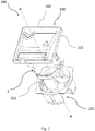
- Figure 1 shows an optical termination assembly 300 comprising an optical termination box 100, a wall mounting element and a support device 1 configured to attach the optical termination box 100 to the wall mounting element.
- the optical termination box 100 comprises a base 101 having connecting portions adjacent to the support device 1 when the optical termination box 100 is attached to the support device 1, and a cover 102 removably attached to the base 101.
- the wall mounting element comprises a wallbox 201 mounted in a wall and having mounting members 202 for removably attaching the support device 1 to the wallbox 201.
- Figure 2 shows a wall mounting element and a support device 1 configured to attach an optical termination box, such as the optical termination box 100 of figure 1 , to the wall mounting element.
- the wall mounting element comprises a rail 220 extending along a longitudinal axis Z-Z and having attaching portions 221 for removably attaching the support device 1 to the rail 220.
- the support device 1 comprises a frame 2 and attachment members 6, 7, 8 projecting from the frame 2 to attach the frame 2 to the optical termination box 100 and to the wall mounting element.
- the attachment members comprise first attachment members 6 configured to attach the frame 2 to the optical termination box 100.
- the attachment members comprise second attachment members 7 configured to attach the frame 2 to the rail 220.
- the attachment members comprise third attachment members 8 configure to attach the frame 2 to the wallbox 201.
- the attachment members comprise the second attachment members 7 and the third attachment members 8 so that the frame 2 can be attached to different types of wall mounting elements respectively through the second attachment members 7 or the third attachment members 8. With this arrangement, the support device 1 increases the mounting flexibility for the operator.
- the frame 2 has a plurality of walls 3 and the attachment members project from the walls 3.
- the walls 3 define an opening 4 and surround the opening 4.
- the frame 2 has a lower portion 2a configured to be arranged adjacent to the rail 220, when the frame 2 is attached to the rail 220. Moreover, the frame 2 has an upper portion 2b configured to be arranged adj acent to the optical termination box 100, when the frame 2 is attached to the optical termination box 100.
- the lower portion 2a and the upper portion 2b define respectively a lower port 3a and an upper port 3b and the opening 4 extends between the lower port 3a and the upper port 3b along a longitudinal direction A-A.
- lower portions 3c of the walls 3 and upper portions 3d of the walls 3 define respectively the lower port 3a and the upper port 3b. More preferably, the walls 3 extends along the longitudinal direction A-A between the respective lower portions 3c and upper portions 3d.
- the first attachment members 6 are formed on the upper portion 2b of the frame 2 and the second attachment members 7 are formed on the lower portion 2a of the frame 2.
- the second attachment members 7 formed on the lower portion 2a of the frame 2 are configured to attach the frame 2 to the rail 220 of figure 2 .
- the frame 2 has opposite first portions 10 spaced apart along a first direction X-X passing through the frame 2. Moreover, the frame 2 has second portions 11 spaced apart along a second direction Y-Y passing through the frame 2 and transversal to the first direction X-X. Namely, first portions 10 are alternated to second portions 11 along the frame 2.
- the first attachment members 6 comprise first protrusions 6a formed on opposite first portions 10 of the frame 2 and the second attachment members 7 comprise second protrusions 7a formed on opposite second portions 11 of the frame 2.
- each first protrusion 6a projects from the walls 3 and comprises a first part 6b projecting away from the opening 4 along a first direction parallel to the longitudinal direction A-A and a second part 6c, joined to the first part 6b, projecting outwardly along a second direction perpendicular to the first direction. More preferably, each first protrusion 6a is L-shaped and extends between a first end portion attached to the wall 3 and a second free end portion. The second free end portions are removably attachable to the connecting portions of the optical termination box 100.
- each second protrusion 7a projects from the walls 3 towards the opening 4.
- Each second protrusion 7a has a tooth configured to engage with the attaching portions 221 of the rail 220.
- the third attachment members 8 are formed on the frame 2 to attach the frame 2 to the wallbox 201 through fastening members, for example screws (not shown in the figures).
- the third attachment members 8 comprise wings 8a which protrude from the walls 3 towards the opening 4, more preferably along a direction perpendicular to the longitudinal direction A-A and are provided with openings 8b for passage of fastening members.
- the second attachment members 7 are formed on the lower portion 2a and the third attachment members 8 are formed on the upper portion 2b.
- the first attachment members 6 and the third attachment members 8 project from the upper portion 2b of the frame in order to install the optical termination box 100 flush with the wall when the frame is inserted in the wallbox 201.
- At least one wall 3 has a resiliently deformable portion which allows the deformation the frame 2 for facilitating the attachment of the optical termination box 100 and the wall mounting element to the support device 1.
- at least one wall 3 is resiliently deformable.
- resilient deformability of the deformable portions and the deformable walls 3 is obtained by choosing a resilient material for the walls 3 or controlling the thickness of the walls 3 during the moulding process.
- the frame 2 is resiliently deformable upon application of forces on the wall 3.
- the walls 3 are mutually connected. More preferably, each wall 3 of the frame 2 is resilient deformable. Even more preferably, the frame 2 comprises at least four walls and even more preferably eight walls.
- the first attachment members 6 are configured to engage at least a portion of the optical termination box 100 and to attach the frame 2 to the optical termination box 100.
- the second attachment members 7 and the third attachment members 8 are configured to engage at least a portion of the wall mounting element and to attach the frame 2 to the wall mounting element.
- the first attachment members 6 are configured to mutually move upon resilient deformation of the deformable portions of the walls 3. More preferably, the second attachment members 7 are also configured to mutually move upon resilient deformation of the resiliently deformable portions of the walls 3.
- the frame 2 is configured to reversibly switch between an undeformed configuration and a deformed configuration. Specifically, the frame 2 is configured to switch from the undeformed configuration to the deformed configuration upon application of forces on the walls 3 of the frame 2 and to switch back from the deformed configuration to the undeformed configuration upon release of the forces.
- the first attachment members 6 and the second attachment members 7 are movable in antagonist way upon application of forces on the walls 3.
- application of compression forces on the walls 3 along the first direction X-X causes deformation of the frame 2 and mutual moving apart of the second portions 11 along the second direction Y-Y and mutual approaching of the first portions 10 along the first direction X-X.
- Application of a compression forces on the walls 3 along the second direction Y-Y causes deformation of the frame 2 and mutual moving apart of the first portions 10 along the first direction X-X and mutual approaching of the second portions 11 along the second direction Y-Y.
- extension forces on the wall 3 along the first direction X-X causes deformation of the frame 2 and mutual moving apart of the first portion 10 along the first direction X-X and the mutual approaching of the second portion 11 along the second direction Y-Y.
- the mutual moving apart of the first opposite portion 10 along the first direction X-X causes the mutual approach of the second attachment members 7 along the first direction X-X and the mutual moving apart of the second attachment members 7 along the first direction X-X.
- the support device 1 is attached to the wallbox 201 having a cavity with a specific shape for example a rectangular shape or octagonal shape.
- the frame 2 is at least partially inserted in the cavity of the wallbox 201.
- the operator firstly attaches the third attachment members 8 to the mounting members 202 of the wallbox 201 through the fastening members, for example screws (not shown in the figures). Due to the fastening of the third attachment member 8, deformation of the walls 3 of the frame 2 is limited by the shape of the wallbox 201.
- the walls 3 can be deformed in order to attach the optical termination box 100 to the wallbox 201.
- the frame 2 is configured to engage at least one connecting portion of the optical termination box 100, and then the walls 3 can be deformed in order to engage the remaining connecting portions of the optical termination box 100.
- the first attachment members 6 formed on one of the first portions 10 are configured to engage corresponding connecting portions of the optical termination box 100. Then, upon application of a force on the termination box 100 along the first direction X-X, the first attachment members 6 engaged with the optical termination box 100 approach the first attachment members 6 formed on the opposite first portions 10. Mutual approaching of the first attachment members 6 allows to engage the first attaching members 6 formed on the opposite first portions 10 with corresponding connecting portions of the optical termination box 100. After the engagement of the connecting portions of the optical termination box 100 with the first attachment members 6 on both first opposite portions 10, the applied force is released and the frame 2 switches back from the deformed configuration to the undeformed configuration. Specifically, upon release the forces, the optical termination box 100 becomes attached to the frame 2 through the first attachment members 6.
- the support device 1 is mounted on the rail 220, preferably a DIN rail.
- the operator can deform the frame 2 applying compression forces on the opposite second portions 11 along the second direction Y-Y. With this compression, the frame 2 switches from the undeformed configuration to the deformed configuration in which the second attachment members 7 are mutually approached along the second direction Y-Y and mutually moved apart along the first direction X-X. Specifically, the deformed configuration of the frame 2 allows the engagement of all second attachment members 7 with the respective connecting portions 221 of the rail 220. More in detail, the frame 2 in the deformed configuration is arranged on the rail 220 with the second attachment members 7 at the respective connecting portions 221.
- the frame 2 switches back from the deformed configuration to the undeformed configuration attaching the second attachment members 7 to connecting portions 221 of the rail 220 thereby attaching the frame 2 to the rail 220.
- the operator can engage the second attachment members 7 formed on two opposite second portions 11 with a connecting portion 221 of the rail 220. Then upon application of forces along the first direction X-X, the frame 2 switches from the undeformed configuration to the deformed configuration in which the second attachment members 7 are approached along the second direction Y-Y and moved apart along the first direction X-X. Consequently, the deformed configuration allows the second attachment members 7 formed on the opposite second portions 11 to respectively engage with the opposite connecting portions 221 of the rail 220. When the second attachment members 7 are engaged with the respective connecting portion 221 of the rail 220, the applied force is released and the frame 2 switches back from the deformed to the undeformed configuration attaching the support device 1 to the rail 220.
- the frame 2 is further deformed in order to attach the optical termination box 100 to the support device 1.
- the optical termination box 100 can be attached to the frame 2 as disclosed with reference to the attachment of the optical termination box 100 to the wallbox 201.
- the frame 2 attached to rail 220 is free to be deformed both along the first direction X-X and along the second direction Y-Y.
- the frame 2 can be switched from the undeformed configuration to the deformed configuration, upon application of forces, allowing the engagement of the connecting portions of optical termination box 100 with the first attachment members 6. Then upon release of forces, the frame 2 switches back from the deformed configuration to the undeformed configuration attaching the optical termination box 100 to the frame 2.
Landscapes
- Engineering & Computer Science (AREA)
- Architecture (AREA)
- Civil Engineering (AREA)
- Structural Engineering (AREA)
- Light Guides In General And Applications Therefor (AREA)
- Optical Couplings Of Light Guides (AREA)
Abstract
Description
- The present invention relates to the field of equipment and components for the connection of optical termination box, e.g a costumer termination boxes, to a wall mounting element e.g. Wall Embedded Standardized Boxes (WESB) or DIN rails.
- A FTTH ("Fiber To The Home") network is an optical access network providing a number of end customers with broadband communication services from operators, i.e. with services requiring data transmission at a very high rate, for example of some Mbit/s.
- Typically, a FTTH network comprises a termination box or cabinet which cooperates with an access network and which is typically located in the basement of the building where the end users reside. An optical trunk cable, hereinafter referred to as "riser cable", exits the termination box and runs through the building from the basement up to all the building floors.
- At each floor of the building, the riser cable may be optically connected to one or more optical cables, hereinafter referred to as "drop cables". Each drop cable typically terminates at its far end into a respective customer optical termination box located within or in proximity of the apartment or office of an end user.
- There is a demand from end users for thinner optical termination boxes having reduced thickness, comparable with the thickness of power sockets. Typically, even if a reduced thickness of the optical termination box is provided, the connection element to the wall mounting element affects increases the thickness of the optical termination box projecting from the wall. Furthermore, after attaching the connection element to the wall mounting element, installation operations of the optical termination box are difficult since screws or other attaching members are needed.
-
DE 10351987 disclose a switchgear having a projecting part on a fixing plate of an embedded part carried out by an intermediary of a mounting clamp with elastic deformation, of the projecting part. The projecting part penetrates into a corresponding opening of the plate. The clamp equipped with a blocking unit in assembled position forms a theft-prevention device. -
US 8403289 discloses a universal bracket provided for mounting electrical boxes. The bracket includes a generally rectangular first plate having at least one aperture defined within the first plate. The aperture is shaped to provide access to an electrical box mounted to the first plate, and further includes first and second pairs of diagonally opposite corners. A second plate extends rearward and substantially perpendicular to the first plate and located proximate a first side of the aperture. The first plate further includes one or more fastening portions and a plurality of mounting holes disposed about the fastening portions. One or more of the mounting holes are positioned for mounting the bracket to a vertical structural member adjacent either of two opposite sides of the bracket or a horizontal element adjacent a third side of the bracket, maintaining a particular bracket orientation. -
EP 2523283 discloses a support for an electrical box having a returning unit e.g. spring-blade, for returning a claw into a retracted position. The frame of the support comprises a return unit, which has an opening through which a screw is engaged. The returning unit comprises a mounting portion, which is movably mounted relative to the frame between a nut and the returning unit. The returning unit comprises an actuating portion e.g. branch, which cooperates with the claw to bring the claw into the retracted position during unscrewing of the screw. - The above mentioned support devices increase the overall thickness of an optical termination box connected thereto.
- The Applicant has tackled the problem of providing a support device capable of attaching an optical termination box to different types of wall mounting elements, while keeping the thickness of the optical termination box projecting from the wall mounting element as small as possible.
- The Applicant has found that a removable attachment between the optical termination box and the wall mounting element is achieved by providing a support device with a resilient deformable frame.
- Therefore, the present invention relates to a support device for attaching an optical termination box to a wall mounting element, the support device comprising a frame having one or more walls, the walls defining an opening and surrounding the opening, attachment members projecting from the frame and comprising first attachment members configured to attach the frame to the optical termination box and second or third attachment members configured to attach the frame to the wall mounting element, wherein at least one wall has a resiliently deformable portion and the first attachment members are configured to mutually move upon resilient deformation of the resiliently deformable portion.
- Preferably, the second attachment members are configured to mutually move upon resilient deformation of the resiliently deformable portion.
- Preferably, the frame has a lower portion configured to be arranged adjacent to the wall mounting element, when the frame is attached to the wall mounting element, the frame has an upper portion configured to be arranged adjacent to the optical termination box, when the frame is attached to the optical termination box.
- Preferably, the first attachment members are formed on the upper portion of the frame, the second attachment members are formed on the lower portion of the frame.
- Preferably, the at least one wall is resiliently deformable.
- Preferably, the frame has a plurality of resiliently deformable walls defining the opening.
- Preferably, the first attachment members comprise first protrusions formed on opposite first portions of the frame, the first portions being spaced apart along a first direction passing through the frame, the second attachment members comprise second protrusions formed on opposite second portions of the frame, the second portions being spaced apart along a second direction passing through the frame and transversal to the first direction.
- Preferably, the frame is configured to reversibly switch between an undeformed configuration and a deformed configuration, the frame is configured to switch from the undeformed configuration to the deformed configuration upon application of forces on the walls of the frame, the frame is configured to switch back from the deformed configuration to the undeformed configuration upon release of the forces.
- Preferably, the first attachment members are configured to engage a portion of the optical termination box when the frame is in undeformed configuration, engage a remaining portion of the optical termination box when the frame switches from the undeformed configuration to the deformed configuration, and attach the frame to the optical termination box when the first attachment members engage respective portions of the optical termination box and the frame switches back from the deformed configuration to the undeformed configuration.
- Preferably, the second attachment members are configured to engage attaching portions of the wall mounting element when the frame switches from the undeformed configuration to the deformed configuration, and to attach the frame to the wall mounting element when the frame switches back from the deformed configuration to the undeformed configuration.
- Preferably, the second attachment members are configured to engage a portion of the wall mounting element when the frame is in undeformed configuration, engage a remaining portion of the wall mounting element when the frame switches from the undeformed configuration to the deformed configuration, and attach the frame to the wall mounting element when the second attachment members engage respective portions of the wall mounting element and the frame switches back from the deformed configuration to the undeformed configuration.
- According to a further aspect, the present invention relates to an optical termination assembly comprising an optical termination box, a wall mounting element, and a support device according to anyone of claims 1-11 attached to the optical termination box and the wall mounting element.
- Preferably, the wall mounting element comprises a wallbox embedded in a wall, the wallbox having mounting members, the support device comprises third attachment members formed on the frame to attach the frame to the wallbox through fastening members attaching the third attachment members to the mounting members of the wallbox.
- Preferably, the wall mounting element comprises a rail extending along a longitudinal axis, the rail having attaching portions coupled with the second attachment members for removably attaching the frame to the rail.
- The present invention will now be described in more detail hereinafter with reference to the accompanying drawings, in which some embodiments of the invention are shown.
-
FIG. 1 is an exploded view of optical termination assembly according to one embodiment of the present invention; -
FIG. 2 is a front view of a support device mounted on a wall mounting element according to one embodiment of the present invention; -
FIG. 3 is a perspective view of the support device ofFIG. 1 andFIG. 2 ; -
FIG. 4 is a top view of the support device ofFIG. 1 andFIG. 2 ; -
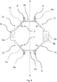
FIG. 5 is a top view of the support device ofFIG. 3 with compression forces applied on to opposite walls of the frame; -
FIG. 6 is a top view of the support device ofFIG. 3 with compression forces applied on to opposite walls of the frame. -
Figure 1 shows anoptical termination assembly 300 comprising anoptical termination box 100, a wall mounting element and asupport device 1 configured to attach theoptical termination box 100 to the wall mounting element. - The
optical termination box 100 comprises abase 101 having connecting portions adjacent to thesupport device 1 when theoptical termination box 100 is attached to thesupport device 1, and acover 102 removably attached to thebase 101. According to the embodiment shown infigure 1 , the wall mounting element comprises awallbox 201 mounted in a wall and having mountingmembers 202 for removably attaching thesupport device 1 to thewallbox 201. -
Figure 2 shows a wall mounting element and asupport device 1 configured to attach an optical termination box, such as theoptical termination box 100 offigure 1 , to the wall mounting element. According to the embodiment shown infigure 2 , the wall mounting element comprises arail 220 extending along a longitudinal axis Z-Z and having attachingportions 221 for removably attaching thesupport device 1 to therail 220. - As shown in
Figures 3-6 , thesupport device 1 comprises aframe 2 andattachment members frame 2 to attach theframe 2 to theoptical termination box 100 and to the wall mounting element. - The attachment members comprise
first attachment members 6 configured to attach theframe 2 to theoptical termination box 100. - According to one embodiment, the attachment members comprise
second attachment members 7 configured to attach theframe 2 to therail 220. - According to an alternative embodiment, the attachment members comprise
third attachment members 8 configure to attach theframe 2 to thewallbox 201. According to a preferred embodiment, the attachment members comprise thesecond attachment members 7 and thethird attachment members 8 so that theframe 2 can be attached to different types of wall mounting elements respectively through thesecond attachment members 7 or thethird attachment members 8. With this arrangement, thesupport device 1 increases the mounting flexibility for the operator. - The
frame 2 has a plurality ofwalls 3 and the attachment members project from thewalls 3. Thewalls 3 define anopening 4 and surround theopening 4. - Preferably, the
frame 2 has alower portion 2a configured to be arranged adjacent to therail 220, when theframe 2 is attached to therail 220. Moreover, theframe 2 has anupper portion 2b configured to be arranged adj acent to theoptical termination box 100, when theframe 2 is attached to theoptical termination box 100. - The
lower portion 2a and theupper portion 2b define respectively a lower port 3a and anupper port 3b and theopening 4 extends between the lower port 3a and theupper port 3b along a longitudinal direction A-A. Preferably,lower portions 3c of thewalls 3 andupper portions 3d of thewalls 3 define respectively the lower port 3a and theupper port 3b. More preferably, thewalls 3 extends along the longitudinal direction A-A between the respectivelower portions 3c andupper portions 3d. - According to one embodiment, the
first attachment members 6 are formed on theupper portion 2b of theframe 2 and thesecond attachment members 7 are formed on thelower portion 2a of theframe 2. Thesecond attachment members 7 formed on thelower portion 2a of theframe 2 are configured to attach theframe 2 to therail 220 offigure 2 . - Preferably, the
frame 2 has oppositefirst portions 10 spaced apart along a first direction X-X passing through theframe 2. Moreover, theframe 2 hassecond portions 11 spaced apart along a second direction Y-Y passing through theframe 2 and transversal to the first direction X-X. Namely,first portions 10 are alternated tosecond portions 11 along theframe 2. - Preferably, the
first attachment members 6 comprisefirst protrusions 6a formed on oppositefirst portions 10 of theframe 2 and thesecond attachment members 7 comprisesecond protrusions 7a formed on oppositesecond portions 11 of theframe 2. - Preferably, each
first protrusion 6a projects from thewalls 3 and comprises afirst part 6b projecting away from theopening 4 along a first direction parallel to the longitudinal direction A-A and asecond part 6c, joined to thefirst part 6b, projecting outwardly along a second direction perpendicular to the first direction. More preferably, eachfirst protrusion 6a is L-shaped and extends between a first end portion attached to thewall 3 and a second free end portion. The second free end portions are removably attachable to the connecting portions of theoptical termination box 100. - Preferably, each
second protrusion 7a projects from thewalls 3 towards theopening 4. Eachsecond protrusion 7a has a tooth configured to engage with the attachingportions 221 of therail 220. - In one embodiment, the
third attachment members 8 are formed on theframe 2 to attach theframe 2 to thewallbox 201 through fastening members, for example screws (not shown in the figures). Preferably, thethird attachment members 8 comprisewings 8a which protrude from thewalls 3 towards theopening 4, more preferably along a direction perpendicular to the longitudinal direction A-A and are provided withopenings 8b for passage of fastening members. - Preferably, the
second attachment members 7 are formed on thelower portion 2a and thethird attachment members 8 are formed on theupper portion 2b. - According to one embodiment, the
first attachment members 6 and thethird attachment members 8 project from theupper portion 2b of the frame in order to install theoptical termination box 100 flush with the wall when the frame is inserted in thewallbox 201. - At least one
wall 3 has a resiliently deformable portion which allows the deformation theframe 2 for facilitating the attachment of theoptical termination box 100 and the wall mounting element to thesupport device 1. Preferably, at least onewall 3 is resiliently deformable. Preferably, resilient deformability of the deformable portions and thedeformable walls 3 is obtained by choosing a resilient material for thewalls 3 or controlling the thickness of thewalls 3 during the moulding process. - According to the preferred embodiment shown in the
figures 3-6 , theframe 2 is resiliently deformable upon application of forces on thewall 3. Preferably, thewalls 3 are mutually connected. More preferably, eachwall 3 of theframe 2 is resilient deformable. Even more preferably, theframe 2 comprises at least four walls and even more preferably eight walls. - The
first attachment members 6 are configured to engage at least a portion of theoptical termination box 100 and to attach theframe 2 to theoptical termination box 100. Thesecond attachment members 7 and thethird attachment members 8 are configured to engage at least a portion of the wall mounting element and to attach theframe 2 to the wall mounting element. - Preferably, the
first attachment members 6 are configured to mutually move upon resilient deformation of the deformable portions of thewalls 3. More preferably, thesecond attachment members 7 are also configured to mutually move upon resilient deformation of the resiliently deformable portions of thewalls 3. - According to one embodiment, the
frame 2 is configured to reversibly switch between an undeformed configuration and a deformed configuration. Specifically, theframe 2 is configured to switch from the undeformed configuration to the deformed configuration upon application of forces on thewalls 3 of theframe 2 and to switch back from the deformed configuration to the undeformed configuration upon release of the forces. - The
first attachment members 6 and thesecond attachment members 7 are movable in antagonist way upon application of forces on thewalls 3. - In particular, application of compression forces on the
walls 3 along the first direction X-X causes deformation of theframe 2 and mutual moving apart of thesecond portions 11 along the second direction Y-Y and mutual approaching of thefirst portions 10 along the first direction X-X. Application of a compression forces on thewalls 3 along the second direction Y-Y causes deformation of theframe 2 and mutual moving apart of thefirst portions 10 along the first direction X-X and mutual approaching of thesecond portions 11 along the second direction Y-Y. Moreover, the application of extension forces on thewall 3 along the first direction X-X causes deformation of theframe 2 and mutual moving apart of thefirst portion 10 along the first direction X-X and the mutual approaching of thesecond portion 11 along the second direction Y-Y. - In detail, the mutual moving apart of the first
opposite portion 10 along the first direction X-X causes the mutual approach of thesecond attachment members 7 along the first direction X-X and the mutual moving apart of thesecond attachment members 7 along the first direction X-X. - With reference to
figure 1 , thesupport device 1 is attached to thewallbox 201 having a cavity with a specific shape for example a rectangular shape or octagonal shape. Specifically, theframe 2 is at least partially inserted in the cavity of thewallbox 201. According to one embodiment, the operator firstly attaches thethird attachment members 8 to the mountingmembers 202 of thewallbox 201 through the fastening members, for example screws (not shown in the figures). Due to the fastening of thethird attachment member 8, deformation of thewalls 3 of theframe 2 is limited by the shape of thewallbox 201. - After attachment of the
support device 1 to thewallbox 201, thewalls 3 can be deformed in order to attach theoptical termination box 100 to thewallbox 201. Specifically, theframe 2 is configured to engage at least one connecting portion of theoptical termination box 100, and then thewalls 3 can be deformed in order to engage the remaining connecting portions of theoptical termination box 100. - Preferably, the
first attachment members 6 formed on one of thefirst portions 10 are configured to engage corresponding connecting portions of theoptical termination box 100. Then, upon application of a force on thetermination box 100 along the first direction X-X, thefirst attachment members 6 engaged with theoptical termination box 100 approach thefirst attachment members 6 formed on the oppositefirst portions 10. Mutual approaching of thefirst attachment members 6 allows to engage the first attachingmembers 6 formed on the oppositefirst portions 10 with corresponding connecting portions of theoptical termination box 100. After the engagement of the connecting portions of theoptical termination box 100 with thefirst attachment members 6 on both firstopposite portions 10, the applied force is released and theframe 2 switches back from the deformed configuration to the undeformed configuration. Specifically, upon release the forces, theoptical termination box 100 becomes attached to theframe 2 through thefirst attachment members 6. - With reference to
figure 2 , thesupport device 1 is mounted on therail 220, preferably a DIN rail. - According to a first embodiment, the operator can deform the
frame 2 applying compression forces on the oppositesecond portions 11 along the second direction Y-Y. With this compression, theframe 2 switches from the undeformed configuration to the deformed configuration in which thesecond attachment members 7 are mutually approached along the second direction Y-Y and mutually moved apart along the first direction X-X. Specifically, the deformed configuration of theframe 2 allows the engagement of allsecond attachment members 7 with the respective connectingportions 221 of therail 220. More in detail, theframe 2 in the deformed configuration is arranged on therail 220 with thesecond attachment members 7 at the respective connectingportions 221. Then, upon positioning theframe 2 on therail 220 and following releasing of forces, theframe 2 switches back from the deformed configuration to the undeformed configuration attaching thesecond attachment members 7 to connectingportions 221 of therail 220 thereby attaching theframe 2 to therail 220. - According to a second embodiment, the operator can engage the
second attachment members 7 formed on two oppositesecond portions 11 with a connectingportion 221 of therail 220. Then upon application of forces along the first direction X-X, theframe 2 switches from the undeformed configuration to the deformed configuration in which thesecond attachment members 7 are approached along the second direction Y-Y and moved apart along the first direction X-X. Consequently, the deformed configuration allows thesecond attachment members 7 formed on the oppositesecond portions 11 to respectively engage with the opposite connectingportions 221 of therail 220. When thesecond attachment members 7 are engaged with the respective connectingportion 221 of therail 220, the applied force is released and theframe 2 switches back from the deformed to the undeformed configuration attaching thesupport device 1 to therail 220. - After the attachment of the
support device 1 to therail 220, theframe 2 is further deformed in order to attach theoptical termination box 100 to thesupport device 1. - According to a first embodiment, the
optical termination box 100 can be attached to theframe 2 as disclosed with reference to the attachment of theoptical termination box 100 to thewallbox 201. - According to a second embodiment, the
frame 2 attached to rail 220 is free to be deformed both along the first direction X-X and along the second direction Y-Y. Theframe 2 can be switched from the undeformed configuration to the deformed configuration, upon application of forces, allowing the engagement of the connecting portions ofoptical termination box 100 with thefirst attachment members 6. Then upon release of forces, theframe 2 switches back from the deformed configuration to the undeformed configuration attaching theoptical termination box 100 to theframe 2.
Claims (14)
- A support device (1) for attaching an optical termination box (100) to a wall mounting element (201, 220), the support device comprising:- a frame (2) having one or more walls (3), the walls (3) defining an opening (4) and surrounding the opening (4);- attachment members projecting from the frame (2) and comprising first attachment members (6) configured to attach the frame (2) to the optical termination box (100) and second or third attachment members (7, 8) configured to attach the frame (2) to the wall mounting element (201, 220),wherein:- at least one wall (3) has a resiliently deformable portion; and- the first attachment members (6) are configured to mutually move upon resilient deformation of the resiliently deformable portion.
- The support device (1) according to claim 1, wherein:- the second attachment members (7) are configured to mutually move upon resilient deformation of the resiliently deformable portion.
- The support device (1) according to claim 1 or 2, wherein:- the frame (2) has a lower portion (2a) configured to be arranged adjacent to the wall mounting element (220), when the frame (2) is attached to the wall mounting element (220);- the frame (2) has an upper portion (2b) configured to be arranged adjacent to the optical termination box (100), when the frame (2) is attached to the optical termination box (100).
- The support device (1) according to claim 3, wherein:- the first attachment members (6) are formed on the upper portion (2b) of the frame (2);- the second attachment members (7) are formed on the lower portion (2a) of the frame (2).
- The support device (1) according to anyone of claims 1 to 4, wherein:- the at least one wall (3) is resiliently deformable.
- The support device (1) according to claim 5, wherein:- the frame (2) has a plurality of resiliently deformable walls (3) defining the opening (4).
- The support device (1) according to anyone of the claims 1 to 6, wherein:- the first attachment members (6) comprise first protrusions (6a) formed on opposite first portions (10) of the frame (2), the first portions (10) being spaced apart along a first direction (X-X) passing through the frame (2),- the second attachment members (7) comprise second protrusions (7a) formed on opposite second portions (11) of the frame (2), the second portions (11) being spaced apart along a second direction (Y-Y) passing through the frame (2) and transversal to the first direction (X-X).
- The support device (1) according to anyone of claims 1 to 7, wherein:- the frame (2) is configured to reversibly switch between an undeformed configuration and a deformed configuration,- the frame (2) is configured to switch from the undeformed configuration to the deformed configuration upon application of forces on the walls (3) of the frame (2),- the frame (2) is configured to switch back from the deformed configuration to the undeformed configuration upon release of the forces.
- The support device (1) according of claim 8, wherein:- the first attachment members (6) are configured to:- engage a portion of the optical termination box (100) when the frame (2) is in undeformed configuration,- engage a remaining portion of the optical termination box (100) when the frame (2) switches from the undeformed configuration to the deformed configuration, and- attach the frame (2) to the optical termination box (100) when the first attachment members (6) engage respective portions of the optical termination box (100) and the frame (2) switches back from the deformed configuration to the undeformed configuration.
- The support device (1) according to claim 8 or 9, wherein:- the second attachment members (7) are configured to:- engage attaching portions of the wall mounting element (220) when the frame (2) switches from the undeformed configuration to the deformed configuration, and- attach the frame (2) to the wall mounting element (220) when the frame (2) switches back from the deformed configuration to the undeformed configuration.
- The support device (1) according to claim 8 or 9, wherein:- the second attachment members (7) are configured to:- engage a portion of the wall mounting element (220) when the frame (2) is in undeformed configuration,- engage a remaining portion of the wall mounting element (220) when the frame (2) switches from the undeformed configuration to the deformed configuration, and- attach the frame (2) to the wall mounting element (220) when the second attachment members (7) engage respective portions of the wall mounting element (220) and the frame (2) switches back from the deformed configuration to the undeformed configuration.
- An optical termination assembly (300) comprising:- an optical termination box (100),- a wall mounting element (201, 220), and- a support device (1) according to anyone of claims 1-11 attached to the optical termination box (100) and the wall mounting element (201, 220).
- The optical termination assembly (300) according to claim 12, wherein:- the wall mounting element (201) comprises a wallbox (201) embedded in a wall, the wallbox (201) having mounting members (202),- the support device (1) comprises third attachment members (8) formed on the frame (2) to attach the frame (2) to the wallbox (201) through fastening members attaching the third attachment members (8) to the mounting members (202) of the wallbox (201).
- The optical termination assembly (300) according to claim 12, wherein:- the wall mounting element (220) comprises a rail (220) extending along a longitudinal axis (Z-Z), the rail (220) having attaching portions (221) coupled with the second attachment members (7) for removably attaching the frame (2) to the rail (220).
Applications Claiming Priority (1)
| Application Number | Priority Date | Filing Date | Title |
|---|---|---|---|
| IT102019000005560A IT201900005560A1 (en) | 2019-04-10 | 2019-04-10 | Support device for fixing an optical termination box to a wall mounting element |
Publications (3)
| Publication Number | Publication Date |
|---|---|
| EP3722852A1 true EP3722852A1 (en) | 2020-10-14 |
| EP3722852B1 EP3722852B1 (en) | 2024-09-04 |
| EP3722852C0 EP3722852C0 (en) | 2024-09-04 |
Family
ID=67108108
Family Applications (1)
| Application Number | Title | Priority Date | Filing Date |
|---|---|---|---|
| EP20164961.3A Active EP3722852B1 (en) | 2019-04-10 | 2020-03-23 | A support device for attaching an optical termination box to a wall mounting element |
Country Status (6)
| Country | Link |
|---|---|
| EP (1) | EP3722852B1 (en) |
| AU (1) | AU2020202282B2 (en) |
| BR (1) | BR102020006982A2 (en) |
| ES (1) | ES3007407T3 (en) |
| IT (1) | IT201900005560A1 (en) |
| PL (1) | PL3722852T3 (en) |
Citations (6)
| Publication number | Priority date | Publication date | Assignee | Title |
|---|---|---|---|---|
| DE10351987A1 (en) | 2002-11-26 | 2004-06-03 | Hager-Electro S.A.S. | Theft-proof electrical device |
| WO2008088035A1 (en) * | 2007-01-19 | 2008-07-24 | Sumitomo Electric Industries, Ltd. | Outlet device |
| EP2517061A1 (en) * | 2009-12-23 | 2012-10-31 | Prysmian S.p.A. | Optical termination assembly |
| EP2523283A1 (en) | 2011-05-13 | 2012-11-14 | Legrand France | Switchgear support provided with extendable and retractable prongs |
| US8403289B1 (en) | 2008-10-15 | 2013-03-26 | Eric R. Rinderer | Universal electric box mounting device |
| US20160109676A1 (en) * | 2014-10-20 | 2016-04-21 | Corning Optical Communications LLC | Convertible fiber optic panel/module assemblies for optical fiber connectivity, including for wall and floor-mounted connectivity applications |
-
2019
- 2019-04-10 IT IT102019000005560A patent/IT201900005560A1/en unknown
-
2020
- 2020-03-23 EP EP20164961.3A patent/EP3722852B1/en active Active
- 2020-03-23 ES ES20164961T patent/ES3007407T3/en active Active
- 2020-03-23 PL PL20164961.3T patent/PL3722852T3/en unknown
- 2020-03-31 AU AU2020202282A patent/AU2020202282B2/en active Active
- 2020-04-07 BR BR102020006982-9A patent/BR102020006982A2/en active IP Right Grant
Patent Citations (6)
| Publication number | Priority date | Publication date | Assignee | Title |
|---|---|---|---|---|
| DE10351987A1 (en) | 2002-11-26 | 2004-06-03 | Hager-Electro S.A.S. | Theft-proof electrical device |
| WO2008088035A1 (en) * | 2007-01-19 | 2008-07-24 | Sumitomo Electric Industries, Ltd. | Outlet device |
| US8403289B1 (en) | 2008-10-15 | 2013-03-26 | Eric R. Rinderer | Universal electric box mounting device |
| EP2517061A1 (en) * | 2009-12-23 | 2012-10-31 | Prysmian S.p.A. | Optical termination assembly |
| EP2523283A1 (en) | 2011-05-13 | 2012-11-14 | Legrand France | Switchgear support provided with extendable and retractable prongs |
| US20160109676A1 (en) * | 2014-10-20 | 2016-04-21 | Corning Optical Communications LLC | Convertible fiber optic panel/module assemblies for optical fiber connectivity, including for wall and floor-mounted connectivity applications |
Also Published As
| Publication number | Publication date |
|---|---|
| ES3007407T3 (en) | 2025-03-20 |
| IT201900005560A1 (en) | 2020-10-10 |
| BR102020006982A2 (en) | 2020-10-20 |
| PL3722852T3 (en) | 2025-02-17 |
| AU2020202282B2 (en) | 2025-03-13 |
| EP3722852B1 (en) | 2024-09-04 |
| AU2020202282A1 (en) | 2020-10-29 |
| EP3722852C0 (en) | 2024-09-04 |
Similar Documents
| Publication | Publication Date | Title |
|---|---|---|
| US10666033B2 (en) | Modular stackable enclosure system | |
| US5913787A (en) | Communications conduit connector mounting device | |
| US7410072B2 (en) | Electrical box extension | |
| US6929140B2 (en) | Universal junction box | |
| US6158180A (en) | Mounting device for communications conduit connector | |
| CA2604882C (en) | Electrical floor access module system | |
| CN102098889B (en) | For the assembling scheme of concealed mounting material | |
| HK1231565A1 (en) | Pivotably attachable fiber optic housing, modular housing system and method | |
| US4627684A (en) | Housing for electrical connectors | |
| EP3722852B1 (en) | A support device for attaching an optical termination box to a wall mounting element | |
| RU2754923C2 (en) | Overhead and executive element, and overhead plate for wall-mounted modular electrical appliances | |
| US6848854B2 (en) | Connector-mounting assembly | |
| EP0702441A1 (en) | Electrical installation apparatus, especially for cable ducts | |
| NZ763155A (en) | A support device for attaching an optical termination box to a wall mounting element | |
| US20190075375A1 (en) | Cable management assembly | |
| CN110959237B (en) | Covers and kits for wall-mounted modular electrical equipment | |
| CZ305497A3 (en) | Low-voltage switchboard | |
| WO2009001055A1 (en) | Electrical and service distribution system | |
| DE202015006719U1 (en) | Cable, device installation and installation trunking system | |
| EP3732518B1 (en) | Optical termination box and optical termination assembly | |
| EP3767767B1 (en) | Corner box assembly | |
| CA2213601C (en) | Communications conduit connector mounting device | |
| KR101444714B1 (en) | A rack structure cabinet for keeping telecommunication equipment and a cable clamping holder braket provided therefor | |
| EP2529383A1 (en) | Group of parts for the wall mounting of at least one modular electrical apparatus | |
| JPH0516813Y2 (en) |
Legal Events
| Date | Code | Title | Description |
|---|---|---|---|
| PUAI | Public reference made under article 153(3) epc to a published international application that has entered the european phase |
Free format text: ORIGINAL CODE: 0009012 |
|
| STAA | Information on the status of an ep patent application or granted ep patent |
Free format text: STATUS: THE APPLICATION HAS BEEN PUBLISHED |
|
| AK | Designated contracting states |
Kind code of ref document: A1 Designated state(s): AL AT BE BG CH CY CZ DE DK EE ES FI FR GB GR HR HU IE IS IT LI LT LU LV MC MK MT NL NO PL PT RO RS SE SI SK SM TR |
|
| AX | Request for extension of the european patent |
Extension state: BA ME |
|
| STAA | Information on the status of an ep patent application or granted ep patent |
Free format text: STATUS: REQUEST FOR EXAMINATION WAS MADE |
|
| 17P | Request for examination filed |
Effective date: 20210407 |
|
| RBV | Designated contracting states (corrected) |
Designated state(s): AL AT BE BG CH CY CZ DE DK EE ES FI FR GB GR HR HU IE IS IT LI LT LU LV MC MK MT NL NO PL PT RO RS SE SI SK SM TR |
|
| STAA | Information on the status of an ep patent application or granted ep patent |
Free format text: STATUS: EXAMINATION IS IN PROGRESS |
|
| 17Q | First examination report despatched |
Effective date: 20220204 |
|
| GRAP | Despatch of communication of intention to grant a patent |
Free format text: ORIGINAL CODE: EPIDOSNIGR1 |
|
| STAA | Information on the status of an ep patent application or granted ep patent |
Free format text: STATUS: GRANT OF PATENT IS INTENDED |
|
| INTG | Intention to grant announced |
Effective date: 20231123 |
|
| RIC1 | Information provided on ipc code assigned before grant |
Ipc: H02G 3/22 20060101ALN20231113BHEP Ipc: H02G 3/18 20060101ALN20231113BHEP Ipc: H02G 3/14 20060101ALI20231113BHEP Ipc: H02G 3/12 20060101ALI20231113BHEP Ipc: H02G 3/08 20060101ALI20231113BHEP Ipc: G02B 6/44 20060101AFI20231113BHEP |
|
| GRAJ | Information related to disapproval of communication of intention to grant by the applicant or resumption of examination proceedings by the epo deleted |
Free format text: ORIGINAL CODE: EPIDOSDIGR1 |
|
| STAA | Information on the status of an ep patent application or granted ep patent |
Free format text: STATUS: EXAMINATION IS IN PROGRESS |
|
| INTC | Intention to grant announced (deleted) | ||
| GRAP | Despatch of communication of intention to grant a patent |
Free format text: ORIGINAL CODE: EPIDOSNIGR1 |
|
| STAA | Information on the status of an ep patent application or granted ep patent |
Free format text: STATUS: GRANT OF PATENT IS INTENDED |
|
| INTG | Intention to grant announced |
Effective date: 20240507 |
|
| GRAS | Grant fee paid |
Free format text: ORIGINAL CODE: EPIDOSNIGR3 |
|
| GRAA | (expected) grant |
Free format text: ORIGINAL CODE: 0009210 |
|
| STAA | Information on the status of an ep patent application or granted ep patent |
Free format text: STATUS: THE PATENT HAS BEEN GRANTED |
|
| AK | Designated contracting states |
Kind code of ref document: B1 Designated state(s): AL AT BE BG CH CY CZ DE DK EE ES FI FR GB GR HR HU IE IS IT LI LT LU LV MC MK MT NL NO PL PT RO RS SE SI SK SM TR |
|
| REG | Reference to a national code |
Ref country code: GB Ref legal event code: FG4D |
|
| REG | Reference to a national code |
Ref country code: CH Ref legal event code: EP |
|
| REG | Reference to a national code |
Ref country code: IE Ref legal event code: FG4D |
|
| REG | Reference to a national code |
Ref country code: DE Ref legal event code: R096 Ref document number: 602020036907 Country of ref document: DE |
|
| U01 | Request for unitary effect filed |
Effective date: 20241018 |
|
| U50 | Request for re-establishment of rights filed [unitary effect] |
Free format text: RE-ESTABLISHMENT OF RIGHTS REQUESTED DUE TO A LATE FILING ON THE REQUEST FOR UNITARY EFFECT Effective date: 20241018 |
|
| U07 | Unitary effect registered |
Designated state(s): AT BE BG DE DK EE FI FR IT LT LU LV MT NL PT RO SE SI Effective date: 20241108 |
|
| U53 | Request for re-establishment of rights accepted [unitary effect] |
Effective date: 20241108 |
|
| PG25 | Lapsed in a contracting state [announced via postgrant information from national office to epo] |
Ref country code: NO Free format text: LAPSE BECAUSE OF FAILURE TO SUBMIT A TRANSLATION OF THE DESCRIPTION OR TO PAY THE FEE WITHIN THE PRESCRIBED TIME-LIMIT Effective date: 20241204 |
|
| U53 | Request for re-establishment of rights accepted [unitary effect] |
Effective date: 20241108 |
|
| PG25 | Lapsed in a contracting state [announced via postgrant information from national office to epo] |
Ref country code: HR Free format text: LAPSE BECAUSE OF FAILURE TO SUBMIT A TRANSLATION OF THE DESCRIPTION OR TO PAY THE FEE WITHIN THE PRESCRIBED TIME-LIMIT Effective date: 20240904 |
|
| PG25 | Lapsed in a contracting state [announced via postgrant information from national office to epo] |
Ref country code: RS Free format text: LAPSE BECAUSE OF FAILURE TO SUBMIT A TRANSLATION OF THE DESCRIPTION OR TO PAY THE FEE WITHIN THE PRESCRIBED TIME-LIMIT Effective date: 20241204 |
|
| REG | Reference to a national code |
Ref country code: GR Ref legal event code: EP Ref document number: 20240402795 Country of ref document: GR Effective date: 20250120 |
|
| PG25 | Lapsed in a contracting state [announced via postgrant information from national office to epo] |
Ref country code: RS Free format text: LAPSE BECAUSE OF FAILURE TO SUBMIT A TRANSLATION OF THE DESCRIPTION OR TO PAY THE FEE WITHIN THE PRESCRIBED TIME-LIMIT Effective date: 20241204 Ref country code: NO Free format text: LAPSE BECAUSE OF FAILURE TO SUBMIT A TRANSLATION OF THE DESCRIPTION OR TO PAY THE FEE WITHIN THE PRESCRIBED TIME-LIMIT Effective date: 20241204 Ref country code: HR Free format text: LAPSE BECAUSE OF FAILURE TO SUBMIT A TRANSLATION OF THE DESCRIPTION OR TO PAY THE FEE WITHIN THE PRESCRIBED TIME-LIMIT Effective date: 20240904 |
|
| REG | Reference to a national code |
Ref country code: ES Ref legal event code: FG2A Ref document number: 3007407 Country of ref document: ES Kind code of ref document: T3 Effective date: 20250320 |
|
| PG25 | Lapsed in a contracting state [announced via postgrant information from national office to epo] |
Ref country code: IS Free format text: LAPSE BECAUSE OF FAILURE TO SUBMIT A TRANSLATION OF THE DESCRIPTION OR TO PAY THE FEE WITHIN THE PRESCRIBED TIME-LIMIT Effective date: 20250104 |
|
| PG25 | Lapsed in a contracting state [announced via postgrant information from national office to epo] |
Ref country code: SM Free format text: LAPSE BECAUSE OF FAILURE TO SUBMIT A TRANSLATION OF THE DESCRIPTION OR TO PAY THE FEE WITHIN THE PRESCRIBED TIME-LIMIT Effective date: 20240904 |
|
| PG25 | Lapsed in a contracting state [announced via postgrant information from national office to epo] |
Ref country code: CZ Free format text: LAPSE BECAUSE OF FAILURE TO SUBMIT A TRANSLATION OF THE DESCRIPTION OR TO PAY THE FEE WITHIN THE PRESCRIBED TIME-LIMIT Effective date: 20240904 |
|
| PG25 | Lapsed in a contracting state [announced via postgrant information from national office to epo] |
Ref country code: SK Free format text: LAPSE BECAUSE OF FAILURE TO SUBMIT A TRANSLATION OF THE DESCRIPTION OR TO PAY THE FEE WITHIN THE PRESCRIBED TIME-LIMIT Effective date: 20240904 |
|
| U20 | Renewal fee for the european patent with unitary effect paid |
Year of fee payment: 6 Effective date: 20250327 |
|
| PGFP | Annual fee paid to national office [announced via postgrant information from national office to epo] |
Ref country code: ES Payment date: 20250401 Year of fee payment: 6 |
|
| PLBE | No opposition filed within time limit |
Free format text: ORIGINAL CODE: 0009261 |
|
| STAA | Information on the status of an ep patent application or granted ep patent |
Free format text: STATUS: NO OPPOSITION FILED WITHIN TIME LIMIT |
|
| 26N | No opposition filed |
Effective date: 20250605 |
|
| PG25 | Lapsed in a contracting state [announced via postgrant information from national office to epo] |
Ref country code: MC Free format text: LAPSE BECAUSE OF FAILURE TO SUBMIT A TRANSLATION OF THE DESCRIPTION OR TO PAY THE FEE WITHIN THE PRESCRIBED TIME-LIMIT Effective date: 20240904 |
|
| REG | Reference to a national code |
Ref country code: CH Ref legal event code: H13 Free format text: ST27 STATUS EVENT CODE: U-0-0-H10-H13 (AS PROVIDED BY THE NATIONAL OFFICE) Effective date: 20251023 |
|
| PG25 | Lapsed in a contracting state [announced via postgrant information from national office to epo] |
Ref country code: CH Free format text: LAPSE BECAUSE OF NON-PAYMENT OF DUE FEES Effective date: 20250331 |
|
| PG25 | Lapsed in a contracting state [announced via postgrant information from national office to epo] |
Ref country code: IE Free format text: LAPSE BECAUSE OF NON-PAYMENT OF DUE FEES Effective date: 20250323 |
|
| PGFP | Annual fee paid to national office [announced via postgrant information from national office to epo] |
Ref country code: GB Payment date: 20260327 Year of fee payment: 7 |
|
| PGFP | Annual fee paid to national office [announced via postgrant information from national office to epo] |
Ref country code: GR Payment date: 20260326 Year of fee payment: 7 Ref country code: PL Payment date: 20260306 Year of fee payment: 7 |
|
| U20 | Renewal fee for the european patent with unitary effect paid |
Year of fee payment: 7 Effective date: 20260327 |