EP3722749A1 - Navigation augmentation system and method - Google Patents
Navigation augmentation system and method Download PDFInfo
- Publication number
- EP3722749A1 EP3722749A1 EP19214594.4A EP19214594A EP3722749A1 EP 3722749 A1 EP3722749 A1 EP 3722749A1 EP 19214594 A EP19214594 A EP 19214594A EP 3722749 A1 EP3722749 A1 EP 3722749A1
- Authority
- EP
- European Patent Office
- Prior art keywords
- navigation
- data
- gyroscope
- accelerometer
- module
- Prior art date
- Legal status (The legal status is an assumption and is not a legal conclusion. Google has not performed a legal analysis and makes no representation as to the accuracy of the status listed.)
- Pending
Links
Images

Classifications
-
- G—PHYSICS
- G01—MEASURING; TESTING
- G01C—MEASURING DISTANCES, LEVELS OR BEARINGS; SURVEYING; NAVIGATION; GYROSCOPIC INSTRUMENTS; PHOTOGRAMMETRY OR VIDEOGRAMMETRY
- G01C21/00—Navigation; Navigational instruments not provided for in groups G01C1/00 - G01C19/00
- G01C21/26—Navigation; Navigational instruments not provided for in groups G01C1/00 - G01C19/00 specially adapted for navigation in a road network
-
- G—PHYSICS
- G01—MEASURING; TESTING
- G01C—MEASURING DISTANCES, LEVELS OR BEARINGS; SURVEYING; NAVIGATION; GYROSCOPIC INSTRUMENTS; PHOTOGRAMMETRY OR VIDEOGRAMMETRY
- G01C21/00—Navigation; Navigational instruments not provided for in groups G01C1/00 - G01C19/00
- G01C21/10—Navigation; Navigational instruments not provided for in groups G01C1/00 - G01C19/00 by using measurements of speed or acceleration
- G01C21/12—Navigation; Navigational instruments not provided for in groups G01C1/00 - G01C19/00 by using measurements of speed or acceleration executed aboard the object being navigated; Dead reckoning
- G01C21/16—Navigation; Navigational instruments not provided for in groups G01C1/00 - G01C19/00 by using measurements of speed or acceleration executed aboard the object being navigated; Dead reckoning by integrating acceleration or speed, i.e. inertial navigation
- G01C21/165—Navigation; Navigational instruments not provided for in groups G01C1/00 - G01C19/00 by using measurements of speed or acceleration executed aboard the object being navigated; Dead reckoning by integrating acceleration or speed, i.e. inertial navigation combined with non-inertial navigation instruments
-
- G—PHYSICS
- G01—MEASURING; TESTING
- G01C—MEASURING DISTANCES, LEVELS OR BEARINGS; SURVEYING; NAVIGATION; GYROSCOPIC INSTRUMENTS; PHOTOGRAMMETRY OR VIDEOGRAMMETRY
- G01C21/00—Navigation; Navigational instruments not provided for in groups G01C1/00 - G01C19/00
- G01C21/26—Navigation; Navigational instruments not provided for in groups G01C1/00 - G01C19/00 specially adapted for navigation in a road network
- G01C21/28—Navigation; Navigational instruments not provided for in groups G01C1/00 - G01C19/00 specially adapted for navigation in a road network with correlation of data from several navigational instruments
- G01C21/30—Map- or contour-matching
-
- G—PHYSICS
- G01—MEASURING; TESTING
- G01C—MEASURING DISTANCES, LEVELS OR BEARINGS; SURVEYING; NAVIGATION; GYROSCOPIC INSTRUMENTS; PHOTOGRAMMETRY OR VIDEOGRAMMETRY
- G01C25/00—Manufacturing, calibrating, cleaning, or repairing instruments or devices referred to in the other groups of this subclass
- G01C25/005—Manufacturing, calibrating, cleaning, or repairing instruments or devices referred to in the other groups of this subclass initial alignment, calibration or starting-up of inertial devices
-
- G—PHYSICS
- G06—COMPUTING OR CALCULATING; COUNTING
- G06F—ELECTRIC DIGITAL DATA PROCESSING
- G06F18/00—Pattern recognition
- G06F18/20—Analysing
- G06F18/25—Fusion techniques
-
- G—PHYSICS
- G06—COMPUTING OR CALCULATING; COUNTING
- G06T—IMAGE DATA PROCESSING OR GENERATION, IN GENERAL
- G06T7/00—Image analysis
- G06T7/20—Analysis of motion
-
- G—PHYSICS
- G06—COMPUTING OR CALCULATING; COUNTING
- G06T—IMAGE DATA PROCESSING OR GENERATION, IN GENERAL
- G06T7/00—Image analysis
- G06T7/20—Analysis of motion
- G06T7/246—Analysis of motion using feature-based methods, e.g. the tracking of corners or segments
-
- G—PHYSICS
- G06—COMPUTING OR CALCULATING; COUNTING
- G06T—IMAGE DATA PROCESSING OR GENERATION, IN GENERAL
- G06T7/00—Image analysis
- G06T7/20—Analysis of motion
- G06T7/277—Analysis of motion involving stochastic approaches, e.g. using Kalman filters
-
- G—PHYSICS
- G06—COMPUTING OR CALCULATING; COUNTING
- G06T—IMAGE DATA PROCESSING OR GENERATION, IN GENERAL
- G06T2207/00—Indexing scheme for image analysis or image enhancement
- G06T2207/10—Image acquisition modality
- G06T2207/10032—Satellite or aerial image; Remote sensing
-
- G—PHYSICS
- G06—COMPUTING OR CALCULATING; COUNTING
- G06T—IMAGE DATA PROCESSING OR GENERATION, IN GENERAL
- G06T2207/00—Indexing scheme for image analysis or image enhancement
- G06T2207/30—Subject of image; Context of image processing
- G06T2207/30244—Camera pose
Definitions
- the present disclosure relates to a navigation augmentation system, and more particularly to a navigation augmentation system without using GPS.
- Precision guided munitions require accurate estimates of position, velocity, and attitude in order to hit a designated target.
- Current weapon systems rely on GPS and high cost IMUs.
- the new paradigm for precision guided munitions is GPS-denied, low cost and volume IMUs, and maximum airframe performance. This patent eliminates major IMU error sources and enables use of IMUs with lower cost and volume than would otherwise be required.
- the conventional methods and systems have generally been considered satisfactory for their intended purpose.
- the present disclosure may provide a solution for at least one of these remaining challenges.
- a navigation augmentation system includes a vehicle, such as an aircraft, missile or projectile, including an imaging device operably connected to a navigation data fusion module configured for receiving and analyzing visual point of interest data, gyroscope data, and accelerometer data, wherein the navigation data fusion module is operably connected to a sensor compensation module and an autopilot module for controlling navigation of the vehicle.
- the accelerometer and the gyroscope can also be directly and operably connected to the sensor compensation module.
- the navigation data fusion module can include a Kalman filter.
- the imaging device can include a series of cameras which can be interconnected or independent of each other, each communicating with the navigation data fusion module.
- Each imaging device can include a horizon sensor.
- a method of augmenting navigation of a vehicle includes updating a vehicle control command due to receiving data from an autopilot module and data from sensors compensation module for controlling a direction of travel of a vehicle wherein the sensor compensation module receives bias and scale factor error estimates for a gyroscope and bias and scale factor error estimates for an accelerometer from a navigation data fusion system wherein the navigation data fusion system receives and aggregates input from an integrator for a gyroscope, an integrator for an accelerometer, and an imaging device, and the vehicle changes direction based on the navigation updates.
- Roll and pitch of the vehicle can be determined by the imaging device when used as a horizon sensor, and can be used as inputs to the navigation data fusion system.
- the roll and pitch of the vehicle can be coupled with the visual points of interest data as an input to the data fusion system.
- the imaging device can detect at least one point of interest in a first image and track the point of interest in a second image using an algorithm.
- the algorithm can be a SIFT (Scale Invariant Feature Transform), FAST (Features from Accelerated Segment Test) algorithm, or similar algorithm.
- the method described above is intended to be used in areas where GPS data is inaccessible or intermittently accessible; as such the bias and scale factor error estimates are calculated without using GPS data, and specifically the vehicle can operate in a GPS denial area.
- Fig. 1 a partial view of an exemplary embodiment of a navigation augmentation system in accordance with the invention is shown in Fig. 1 and is designated generally by reference character 100.
- the methods and systems of the invention can be used to bound the change in position and attitude by estimating the bias and scale factor errors of the accelerometers and gyroscopes of a vehicle in flight.
- the imaging seeker is used to capture images at fixed intervals. Each recorded image is scanned for points of interest (POI) which can be tracked or matched in successive images. Given many such points, a least-squares estimate of the camera's change in roll, pitch, yaw, and translation direction can be calculated for each pair of images.
- the translation direction vector must be multiplied by a scaling factor, a, which can be determined using an additional information source, i.e. an altimeter, velocity, or position measurement within the image. These can be used as aiding information to enhance navigation estimates.
- a navigation augmentation system 100 includes a vehicle 101, specifically an airborne vehicle such aircraft or a munition, including an imaging device 102 operably connected to a navigation data fusion module 104 configured for receiving and analyzing delta rotations and delta translations (from block 3), gyroscope data, and accelerometer data.
- the navigation data fusion module 104 is operably connected to a sensor compensation module 106 and an autopilot module 108 for controlling the vehicle 101.
- An accelerometer 110 and a gyroscope 112 are also directly and operably connected to the sensor compensation module 106.
- the navigation data fusion module 104 could be implemented as a Kalman filter.
- the imaging device 102 can include a series of cameras which can be interconnected or independent of each other, each with independent translation/rotation estimation modules ((1)-(3)), each providing delta translation/rotation angles to the navigation data fusion module 104. Each imaging device can be used as a horizon sensor.
- a method of augmenting navigation of a vehicle is also disclosed. Any feature detection method that provides a list of unique points can be used, so long as the same point can be detected or tracked in the second image, i.e. the FAST or the SIFT algorithm.
- p nx is the pixel column of the n th point and p ny is the pixel row of the n th point.
- Each of these homogeneous points can be treated as a 3-dimensional pointing vector from the optical center of the camera towards the point in 3D space, where the camera is at the origin and its center pixel points along the Z axis, where the X axis aligns to the image rows and the Y axis aligns to the image columns.
- a matching point For each of the points identified in the first image, a matching point must be located in the second image.
- the points can be located using a tracking algorithm.
- KLT Kanade-Lucas-Tomasi
- a plane can be defined using the point P, and the optical centers (lenses) of each camera - O and O'.
- [t ⁇ ] is the skew symmetric form of t, which is the implementation of the cross-product with a matrix multiplication.
- the essential matrix is defined using normalized camera coordinates, accounting for the camera's intrinsic parameters (focal length, etc.)
- a least-squares estimate of the fundamental matrix can be computed, which contains the desired rotation and translation information.
- the fundamental matrix can now be estimated using standard linear least-squares techniques.
- K f 0 c x 0 f c y 0 0 1
- f is the focal length expressed in number of pixels and c x and c y are the pixel column and row aligned with the lens's optical axis.
- U and V are rotation matrices and W is a diagonal matrix containing the singular values. Due to the defined constraints of the essential matrix, it must have rank 2, and therefore only contain 2 singular values. This means that the third column of U defines the null space of ⁇ . Since ⁇ is defined as the product of one rotation matrix and one skew-symmetric matrix representing the translation vector, the vector t' is the null space of ⁇ and therefore the 3 rd column of U. It is only defined by its direction, and at the moment it could be positive or negative.
- This information can then be used to extract the delta attitude and delta relative position between frames, which can then be applied as an aiding source to a navigation algorithm.
- the method includes updating a vehicle control command from an autopilot module 108 and data from sensors compensation module 106 for controlling a direction of travel of a vehicle wherein the sensor compensation module 106 receives bias and scale factor error estimates for a gyroscope 112 and bias and scale factor error estimates for an accelerometer 110 from a navigation data fusion system 104 wherein the navigation data fusion system 104 receives an aggregate input from an integrator for a gyroscope 113, an integrator for an accelerometer 111, and an imaging device 102, and the vehicle changes direction based on the navigation updates. Change in position, velocity and attitude of the vehicle are determined by the accelerometer and the gyroscope integrators and used as inputs to the navigation data fusion system.
- the visual points of interest data are processed to estimate delta translation and rotation of the imager, which is used as an input to the data fusion system.
- the data fusion system uses the delta attitude and delta relative positions to compare to the attitude and position changes estimated by the gyroscope and accelerometers. The difference between the two is specified as bias and scale factor error of the gyroscope and accelerometers, as the imaging device has bias-free error characteristics.
- the sensor fusion module uses these error terms to compensate the gyroscope and accelerometer outputs.
- the imaging device 102 can detect at least one point of interest in a first image and track the point of interest in a second image.
- the detection algorithm can be the SIFT or the FAST algorithm.
- the system uses an imaging seeker to track multiple distinguishable terrain features (i.e. rivers, lakes, roads, shoreline, rock formations, vegetation, etc.) which are assumed to be on the surface, and inertially fixed.
- An imaging sensor provides angle-only measurements (with respect to the body) to each feature. Tracking these features allows delta-position, delta-attitude, and velocity to be bounded while navigating via dead-reckoning by using features as an aid to navigation.
- This system and method enhance integrated guidance units to operate by improving attitude and position estimates and seeker acquisition capabilities.
- the systems allows for using small, low cost sensors, which can be calibrated post launch.
- This system and method disclosed above remove gyro and accelerometer scale factor and bias, which are major error sources of low cost units, and improve navigation, airframe stability, and guidance accuracy.
- the method described above is intended to be used in areas where GPS data is inaccessible or intermittently accessible, as such the bias and scale factor error estimates are calculated without using GPS data.
Landscapes
- Engineering & Computer Science (AREA)
- Radar, Positioning & Navigation (AREA)
- Remote Sensing (AREA)
- General Physics & Mathematics (AREA)
- Physics & Mathematics (AREA)
- Theoretical Computer Science (AREA)
- Computer Vision & Pattern Recognition (AREA)
- Automation & Control Theory (AREA)
- Multimedia (AREA)
- Data Mining & Analysis (AREA)
- Bioinformatics & Cheminformatics (AREA)
- Bioinformatics & Computational Biology (AREA)
- Evolutionary Biology (AREA)
- Evolutionary Computation (AREA)
- General Engineering & Computer Science (AREA)
- Artificial Intelligence (AREA)
- Life Sciences & Earth Sciences (AREA)
- Manufacturing & Machinery (AREA)
- Navigation (AREA)
- Traffic Control Systems (AREA)
Abstract
Description
- The present disclosure relates to a navigation augmentation system, and more particularly to a navigation augmentation system without using GPS.
- A variety of devices are known in the navigation systems for vehicles. Precision guided munitions require accurate estimates of position, velocity, and attitude in order to hit a designated target. Current weapon systems rely on GPS and high cost IMUs. The new paradigm for precision guided munitions is GPS-denied, low cost and volume IMUs, and maximum airframe performance. This patent eliminates major IMU error sources and enables use of IMUs with lower cost and volume than would otherwise be required.
- The conventional methods and systems have generally been considered satisfactory for their intended purpose. However, there is still a need in the art for low-cost navigation systems operating in a GPS-denied environment but maintaining accurate position, velocity, and attitude estimates, which in turn improve seeker target acquisition capabilities. There also remains a need in the art for such systems and components that are economically viable. The present disclosure may provide a solution for at least one of these remaining challenges.
- A navigation augmentation system includes a vehicle, such as an aircraft, missile or projectile, including an imaging device operably connected to a navigation data fusion module configured for receiving and analyzing visual point of interest data, gyroscope data, and accelerometer data, wherein the navigation data fusion module is operably connected to a sensor compensation module and an autopilot module for controlling navigation of the vehicle. The accelerometer and the gyroscope can also be directly and operably connected to the sensor compensation module. The navigation data fusion module can include a Kalman filter.
- The imaging device can include a series of cameras which can be interconnected or independent of each other, each communicating with the navigation data fusion module. Each imaging device can include a horizon sensor.
- A method of augmenting navigation of a vehicle is also disclosed. The method includes updating a vehicle control command due to receiving data from an autopilot module and data from sensors compensation module for controlling a direction of travel of a vehicle wherein the sensor compensation module receives bias and scale factor error estimates for a gyroscope and bias and scale factor error estimates for an accelerometer from a navigation data fusion system wherein the navigation data fusion system receives and aggregates input from an integrator for a gyroscope, an integrator for an accelerometer, and an imaging device, and the vehicle changes direction based on the navigation updates. Roll and pitch of the vehicle can be determined by the imaging device when used as a horizon sensor, and can be used as inputs to the navigation data fusion system. The roll and pitch of the vehicle can be coupled with the visual points of interest data as an input to the data fusion system.
- The imaging device can detect at least one point of interest in a first image and track the point of interest in a second image using an algorithm. The algorithm can be a SIFT (Scale Invariant Feature Transform), FAST (Features from Accelerated Segment Test) algorithm, or similar algorithm.
- The method described above is intended to be used in areas where GPS data is inaccessible or intermittently accessible; as such the bias and scale factor error estimates are calculated without using GPS data, and specifically the vehicle can operate in a GPS denial area.
- These and other features of the systems and methods of the subject disclosure will become more readily apparent to those skilled in the art from the following detailed description of the preferred embodiments taken in conjunction with the drawings.
- So that those skilled in the art to which the subject invention appertains will readily understand how to make and use the devices and methods of the subject invention without undue experimentation, preferred embodiments thereof will be described in detail herein below with reference to certain figures, wherein:
-
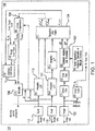
Fig. 1 is a schematic view of a navigation augmentation system; and -
Fig. 2 is a 2-D Camera Rotation/Translation Diagram for the navigation augmentation system ofFig. 1 . - Reference will now be made to the drawings wherein like reference numerals identify similar structural features or aspects of the subject invention. For purposes of explanation and illustration, and not limitation, a partial view of an exemplary embodiment of a navigation augmentation system in accordance with the invention is shown in
Fig. 1 and is designated generally byreference character 100. The methods and systems of the invention can be used to bound the change in position and attitude by estimating the bias and scale factor errors of the accelerometers and gyroscopes of a vehicle in flight. - During flight, the imaging seeker is used to capture images at fixed intervals. Each recorded image is scanned for points of interest (POI) which can be tracked or matched in successive images. Given many such points, a least-squares estimate of the camera's change in roll, pitch, yaw, and translation direction can be calculated for each pair of images. The translation direction vector must be multiplied by a scaling factor, a, which can be determined using an additional information source, i.e. an altimeter, velocity, or position measurement within the image. These can be used as aiding information to enhance navigation estimates.
- A
navigation augmentation system 100 includes avehicle 101, specifically an airborne vehicle such aircraft or a munition, including animaging device 102 operably connected to a navigationdata fusion module 104 configured for receiving and analyzing delta rotations and delta translations (from block 3), gyroscope data, and accelerometer data. The navigationdata fusion module 104 is operably connected to asensor compensation module 106 and anautopilot module 108 for controlling thevehicle 101. Anaccelerometer 110 and agyroscope 112 are also directly and operably connected to thesensor compensation module 106. The navigationdata fusion module 104 could be implemented as a Kalman filter. - The
imaging device 102 can include a series of cameras which can be interconnected or independent of each other, each with independent translation/rotation estimation modules ((1)-(3)), each providing delta translation/rotation angles to the navigationdata fusion module 104. Each imaging device can be used as a horizon sensor. - A method of augmenting navigation of a vehicle is also disclosed. Any feature detection method that provides a list of unique points can be used, so long as the same point can be detected or tracked in the second image, i.e. the FAST or the SIFT algorithm. The output of an imaging collection can be a matrix of points, p in homogeneous coordinates:

- Where pnx is the pixel column of the nth point and pny is the pixel row of the nth point. Each of these homogeneous points can be treated as a 3-dimensional pointing vector from the optical center of the camera towards the point in 3D space, where the camera is at the origin and its center pixel points along the Z axis, where the X axis aligns to the image rows and the Y axis aligns to the image columns.
- For each of the points identified in the first image, a matching point must be located in the second image. In the case where there is relatively little motion between successive camera frames, as in a high frame-rate video stream, the points can be located using a tracking algorithm. One method for tracking is to consider a small region of pixels around the POI of the first image and search the second image for the nearby region with the highest correlation:

- px ' and py ' are the corresponding column and row of point p in the second image
- R is a small region of pixels around p
- I is the first image
- I' is the second image
- Other methods, such as the method above but with a Kalman filter, or the Kanade-Lucas-Tomasi (KLT) tracker can be used. As an alternative to feature tracking, feature matching can also be performed.
- The output of this step is a second matrix of points, p' in homogeneous coordinates:

- Where a correspondence between the points is maintained via indices. If a matching point cannot be located in the second image, it is removed from the list.
- For every point in 3-dimensional space that is observed from two different camera locations, a plane can be defined using the point P, and the optical centers (lenses) of each camera - O and O'.

- The line OO' is the direction of translation between frames k and k+1, and the lines OP and O'P are the lines connecting each camera's optical center to the point in 3-dimensional space. Since these points define a plane, the following relation holds:

- This can be re-written using the coordinates of the first camera as:

- Where t is the translation and R is the rotation matrix from the second camera orientation to the first camera orientation. The essential matrix is defined as:

- Where [t×] is the skew symmetric form of t, which is the implementation of the cross-product with a matrix multiplication. The essential matrix is defined using normalized camera coordinates, accounting for the camera's intrinsic parameters (focal length, etc.) The transformation between the essential matrix and the fundamental matrix is linear:

- Where K is the camera calibration matrix. This will be defined and handled in the following step. For the moment, for each point (defined in pixel coordinates) that exists in both images, the following relation holds:

- Using the set of point correspondences acquired in the previous steps, a least-squares estimate of the fundamental matrix can be computed, which contains the desired rotation and translation information.
- The equation can be rewritten to allow for a solution using standard linear least-squares optimization techniques:
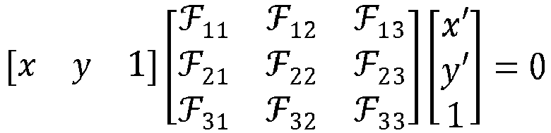
- This is a system of nine homogeneous linear equations:



- The fundamental matrix can now be estimated using standard linear least-squares techniques.
- The fundamental matrix estimate does not account for the camera's focal length, focal center, and pixel size, however, it is linearly related to the desired essential matrix:

- Where K is the camera calibration matrix, and predetermined, or sometimes called the intrinsic matrix, is defined as:

- Where f is the focal length expressed in number of pixels and cx and cy are the pixel column and row aligned with the lens's optical axis.
- To extract the rotation and translation vectors from the essential matrix, the singular value decomposition is utilized:

- Where U and V are rotation matrices and W is a diagonal matrix containing the singular values. Due to the defined constraints of the essential matrix, it must have
rank 2, and therefore only contain 2 singular values. This means that the third column of U defines the null space of ε. Since ε is defined as the product of one rotation matrix and one skew-symmetric matrix representing the translation vector, the vector t' is the null space of ε and therefore the 3rd column of U. It is only defined by its direction, and at the moment it could be positive or negative. - There are also two possibilities for the rotation matrix R depending on the ordering of the first two columns of U. Using the four total combinations of R and t', only one of these will result in the points being in front of the camera in both positions, and this provides the estimate of R and t'. The translation vector t', is a unit vector, therefore the scaling factor, a, must be multiplied by t' in order to have a properly scaled delta relative position.

- This information can then be used to extract the delta attitude and delta relative position between frames, which can then be applied as an aiding source to a navigation algorithm.
- The method includes updating a vehicle control command from an
autopilot module 108 and data fromsensors compensation module 106 for controlling a direction of travel of a vehicle wherein thesensor compensation module 106 receives bias and scale factor error estimates for agyroscope 112 and bias and scale factor error estimates for anaccelerometer 110 from a navigationdata fusion system 104 wherein the navigationdata fusion system 104 receives an aggregate input from an integrator for agyroscope 113, an integrator for anaccelerometer 111, and animaging device 102, and the vehicle changes direction based on the navigation updates. Change in position, velocity and attitude of the vehicle are determined by the accelerometer and the gyroscope integrators and used as inputs to the navigation data fusion system. The visual points of interest data are processed to estimate delta translation and rotation of the imager, which is used as an input to the data fusion system. The data fusion system uses the delta attitude and delta relative positions to compare to the attitude and position changes estimated by the gyroscope and accelerometers. The difference between the two is specified as bias and scale factor error of the gyroscope and accelerometers, as the imaging device has bias-free error characteristics. The sensor fusion module uses these error terms to compensate the gyroscope and accelerometer outputs. This gives the compensated gyroscope output


- The
imaging device 102 can detect at least one point of interest in a first image and track the point of interest in a second image. The detection algorithm can be the SIFT or the FAST algorithm. The system uses an imaging seeker to track multiple distinguishable terrain features (i.e. rivers, lakes, roads, shoreline, rock formations, vegetation, etc.) which are assumed to be on the surface, and inertially fixed. An imaging sensor provides angle-only measurements (with respect to the body) to each feature. Tracking these features allows delta-position, delta-attitude, and velocity to be bounded while navigating via dead-reckoning by using features as an aid to navigation. - This system and method enhance integrated guidance units to operate by improving attitude and position estimates and seeker acquisition capabilities. The systems allows for using small, low cost sensors, which can be calibrated post launch. This system and method disclosed above remove gyro and accelerometer scale factor and bias, which are major error sources of low cost units, and improve navigation, airframe stability, and guidance accuracy.
- The method described above is intended to be used in areas where GPS data is inaccessible or intermittently accessible, as such the bias and scale factor error estimates are calculated without using GPS data.
- The methods and systems of the present disclosure, as described above and shown in the drawings, provide for flight systems with superior properties including increased reliability and stability, and reduced size, weight, complexity, and/or cost. While the apparatus and methods of the subject disclosure have been showing and described with reference to embodiments, those skilled in the art will readily appreciate that changes and/or modifications may be made thereto without departing from the scope of the subject disclosure.
Claims (15)
- A navigation augmentation system comprising:a vehicle (101) including an imaging device (102) operably connected to a navigation data fusion module (104) configured for receiving and analyzing visual point of interest data, gyroscope data, and accelerometer data;wherein the navigation data fusion module (104) is operably connected to a sensor compensation module and an autopilot module for controlling the navigation of the vehicle.
- The navigation augmentation system of claim 1, wherein the accelerometer is operably connected to the sensor compensation module;
- The navigation system of claim 1 or 2, wherein the gyroscope is operably connected to the sensor compensation module.
- The navigation system of any preceding claim, wherein navigation data fusion module includes a Kalman filter.
- The navigation system of any preceding claim, wherein the imaging device includes a series of independent cameras.
- The navigation system of any preceding claim, wherein the imaging device includes a horizon sensor.
- A method of augmenting navigation of a vehicle comprising:updating a vehicle control command due to receiving data from an autopilot module and data from sensors compensation module and data from a guidance module for controlling a vehicle;wherein the sensor compensation module receives bias and scale factor error estimates for a gyroscope and bias and scale factor error estimates for an accelerometer from a navigation data fusion system; andthe navigation data fusion system receiving and aggregating input from an integrator for a gyroscope, an integrator for an accelerometer, and an imaging device.
- The method of claim 7, wherein the sensor compensation module adjusts the angular rate sensed by the gyroscope based upon the estimated gyroscope bias and scale factors.
- The method of claim 7 or 8, wherein the sensor compensation module adjusts the acceleration sensed by the accelerometer based upon the estimated accelerometer bias and scale factors.
- The method of any of claims 7-9 wherein the imaging device detects at least one point of interest in a first image and tracks the point of interest in a second image using a feature-tracking algorithm.
- The method of claim 10, wherein the feature-tracking algorithm receives scale information from an altitude estimate, velocity estimate, or estimated distance in the imaging information to provide scale to at least one point of interest is the first image and the second image; and/or wherein the feature-tracking algorithm is a scale-invariant feature transform (SIFT) algorithm.
- The method of any of claims 7-10, wherein an algorithm is configured to determine the change in attitude and the change in relative position between the first and second images by applying a least-squares fit to satisfy epipolar geometry of at least one point of interest in a first image and the point of interest tracked in a second image, and preferably wherein the navigation data fusion system receives from the algorithm an estimated attitude change independent of an estimated relative position change.
- The method of any of claims 7-12 wherein the accelerometer supplies acceleration vector data directly to the sensor compensation module.
- The method of any of claims 7-13, wherein the gyroscope supplies angular acceleration vector data directly to the sensor compensation module, and preferably wherein the navigation data fusion system compares estimated attitude and estimated relative position change to the gyroscope and accelerometer data to determine the bias and the scale factor errors.
- The method of any of claims 7-14, wherein bias and scale factor error estimates are calculated without using GPS data; and/or wherein roll and pitch are determined and used as an input to the navigation data fusion system and the roll and pitch of the vehicle are coupled with change in attitude and change in relative position as an input to the navigation data fusion system; and/or wherein the vehicle changes direction based on the navigation updates.
Applications Claiming Priority (1)
| Application Number | Priority Date | Filing Date | Title |
|---|---|---|---|
| US16/379,210 US11037018B2 (en) | 2019-04-09 | 2019-04-09 | Navigation augmentation system and method |
Publications (1)
| Publication Number | Publication Date |
|---|---|
| EP3722749A1 true EP3722749A1 (en) | 2020-10-14 |
Family
ID=68841000
Family Applications (1)
| Application Number | Title | Priority Date | Filing Date |
|---|---|---|---|
| EP19214594.4A Pending EP3722749A1 (en) | 2019-04-09 | 2019-12-09 | Navigation augmentation system and method |
Country Status (3)
| Country | Link |
|---|---|
| US (1) | US11037018B2 (en) |
| EP (1) | EP3722749A1 (en) |
| CA (1) | CA3064640C (en) |
Cited By (1)
| Publication number | Priority date | Publication date | Assignee | Title |
|---|---|---|---|---|
| WO2022037749A1 (en) * | 2020-08-17 | 2022-02-24 | Continental Automotive Gmbh | Method for calibrating a yaw rate sensor of a vehicle |
Families Citing this family (2)
| Publication number | Priority date | Publication date | Assignee | Title |
|---|---|---|---|---|
| US12260634B2 (en) * | 2023-03-01 | 2025-03-25 | L3Harris Technologies, Inc. | Attitude error observations from image relative motions |
| CN116165690B (en) * | 2023-04-21 | 2023-07-07 | 山西省娄烦县皇姑山矿业有限责任公司 | A GNSS/INS-based dual adaptive factor combined navigation and positioning method |
Citations (3)
| Publication number | Priority date | Publication date | Assignee | Title |
|---|---|---|---|---|
| WO2014130854A1 (en) * | 2013-02-21 | 2014-08-28 | Regents Of The Univesity Of Minnesota | Extrinsic parameter calibration of a vision-aided inertial navigation system |
| EP3049821A2 (en) * | 2013-09-27 | 2016-08-03 | Qualcomm Incorporated | Exterior hybrid photo mapping |
| US20170023937A1 (en) * | 2015-07-24 | 2017-01-26 | The Trustees Of The University Of Pennsylvania | Systems, devices, and methods for on-board sensing and control of micro aerial vehicles |
Family Cites Families (3)
| Publication number | Priority date | Publication date | Assignee | Title |
|---|---|---|---|---|
| US6072889A (en) | 1997-12-03 | 2000-06-06 | The Raytheon Company | Method and system for imaging target detection |
| WO2017068331A1 (en) | 2015-10-20 | 2017-04-27 | Mbda Uk Limited | Improvements in and relating to missile targeting |
| US20180087907A1 (en) * | 2016-09-29 | 2018-03-29 | The Charles Stark Draper Laboratory, Inc. | Autonomous vehicle: vehicle localization |
-
2019
- 2019-04-09 US US16/379,210 patent/US11037018B2/en active Active
- 2019-12-09 EP EP19214594.4A patent/EP3722749A1/en active Pending
- 2019-12-10 CA CA3064640A patent/CA3064640C/en active Active
Patent Citations (3)
| Publication number | Priority date | Publication date | Assignee | Title |
|---|---|---|---|---|
| WO2014130854A1 (en) * | 2013-02-21 | 2014-08-28 | Regents Of The Univesity Of Minnesota | Extrinsic parameter calibration of a vision-aided inertial navigation system |
| EP3049821A2 (en) * | 2013-09-27 | 2016-08-03 | Qualcomm Incorporated | Exterior hybrid photo mapping |
| US20170023937A1 (en) * | 2015-07-24 | 2017-01-26 | The Trustees Of The University Of Pennsylvania | Systems, devices, and methods for on-board sensing and control of micro aerial vehicles |
Non-Patent Citations (1)
| Title |
|---|
| KRIEGER EVAN ET AL: "Long Short Working Memory (LSWM) Integration with Polynomial Connectivity for Object Tracking in Wide Area Motion Imagery", 2018 15TH IEEE INTERNATIONAL CONFERENCE ON ADVANCED VIDEO AND SIGNAL BASED SURVEILLANCE (AVSS), IEEE, 27 November 2018 (2018-11-27), pages 1 - 6, XP033518191, [retrieved on 20190211], DOI: 10.1109/AVSS.2018.8639095 * |
Cited By (1)
| Publication number | Priority date | Publication date | Assignee | Title |
|---|---|---|---|---|
| WO2022037749A1 (en) * | 2020-08-17 | 2022-02-24 | Continental Automotive Gmbh | Method for calibrating a yaw rate sensor of a vehicle |
Also Published As
| Publication number | Publication date |
|---|---|
| US11037018B2 (en) | 2021-06-15 |
| BR102019026557A2 (en) | 2020-10-20 |
| CA3064640A1 (en) | 2020-10-09 |
| CA3064640C (en) | 2026-01-20 |
| US20200327355A1 (en) | 2020-10-15 |
Similar Documents
| Publication | Publication Date | Title |
|---|---|---|
| US10515458B1 (en) | Image-matching navigation method and apparatus for aerial vehicles | |
| US7071970B2 (en) | Video augmented orientation sensor | |
| Bryson et al. | Building a robust implementation of bearing‐only inertial SLAM for a UAV | |
| US20200124421A1 (en) | Method and apparatus for estimating position | |
| CN107727079B (en) | Target positioning method of full-strapdown downward-looking camera of micro unmanned aerial vehicle | |
| CN112230242A (en) | Pose estimation system and method | |
| US7778534B2 (en) | Method and apparatus of correcting geometry of an image | |
| US20040246463A1 (en) | Method and apparatus for optical inertial measurement | |
| EP2322902B1 (en) | System and method for determining heading | |
| Caballero et al. | Unmanned aerial vehicle localization based on monocular vision and online mosaicking: a new mapping framework | |
| CA3064640C (en) | Navigation augmentation system and method | |
| Abdi et al. | Pose estimation of unmanned aerial vehicles based on a vision-aided multi-sensor fusion | |
| Beauvisage et al. | Robust multispectral visual-inertial navigation with visual odometry failure recovery | |
| Angelino et al. | High altitude UAV navigation using IMU, GPS and camera | |
| US20250251242A1 (en) | System for aircraft navigation based on image processing | |
| CN112902957B (en) | Missile-borne platform navigation method and system | |
| Zhao et al. | Distributed filtering-based autonomous navigation system of UAV | |
| Veth et al. | Two-dimensional stochastic projections for tight integration of optical and inertial sensors for navigation | |
| Aminzadeh et al. | Implementation and performance evaluation of optical flow navigation system under specific conditions for a flying robot | |
| Veth et al. | Tightly-coupled ins, gps, and imaging sensors for precision geolocation | |
| Carozza et al. | Error analysis of satellite attitude determination using a vision-based approach | |
| WO2020219665A1 (en) | System and method for navigating over water | |
| CN114322943B (en) | Target distance measuring method and device based on forward-looking image of unmanned aerial vehicle | |
| Beauvisage et al. | Multimodal visual-inertial odometry for navigation in cold and low contrast environment | |
| Chathuranga et al. | Aerial image matching based relative localization of a uav in urban environments |
Legal Events
| Date | Code | Title | Description |
|---|---|---|---|
| PUAI | Public reference made under article 153(3) epc to a published international application that has entered the european phase |
Free format text: ORIGINAL CODE: 0009012 |
|
| STAA | Information on the status of an ep patent application or granted ep patent |
Free format text: STATUS: THE APPLICATION HAS BEEN PUBLISHED |
|
| AK | Designated contracting states |
Kind code of ref document: A1 Designated state(s): AL AT BE BG CH CY CZ DE DK EE ES FI FR GB GR HR HU IE IS IT LI LT LU LV MC MK MT NL NO PL PT RO RS SE SI SK SM TR |
|
| AX | Request for extension of the european patent |
Extension state: BA ME |
|
| STAA | Information on the status of an ep patent application or granted ep patent |
Free format text: STATUS: REQUEST FOR EXAMINATION WAS MADE |
|
| 17P | Request for examination filed |
Effective date: 20210413 |
|
| RBV | Designated contracting states (corrected) |
Designated state(s): AL AT BE BG CH CY CZ DE DK EE ES FI FR GB GR HR HU IE IS IT LI LT LU LV MC MK MT NL NO PL PT RO RS SE SI SK SM TR |
|
| STAA | Information on the status of an ep patent application or granted ep patent |
Free format text: STATUS: EXAMINATION IS IN PROGRESS |
|
| 17Q | First examination report despatched |
Effective date: 20230428 |