EP3722653A1 - Combined hydrogen storage - compression system for the filling of high pressure hydrogen tanks - Google Patents
Combined hydrogen storage - compression system for the filling of high pressure hydrogen tanks Download PDFInfo
- Publication number
- EP3722653A1 EP3722653A1 EP19167968.7A EP19167968A EP3722653A1 EP 3722653 A1 EP3722653 A1 EP 3722653A1 EP 19167968 A EP19167968 A EP 19167968A EP 3722653 A1 EP3722653 A1 EP 3722653A1
- Authority
- EP
- European Patent Office
- Prior art keywords
- hydrogen
- hydrogen storage
- equal
- pressure
- bar
- Prior art date
- Legal status (The legal status is an assumption and is not a legal conclusion. Google has not performed a legal analysis and makes no representation as to the accuracy of the status listed.)
- Withdrawn
Links
- 229910052739 hydrogen Inorganic materials 0.000 title claims abstract description 105
- 239000001257 hydrogen Substances 0.000 title claims abstract description 105
- UFHFLCQGNIYNRP-UHFFFAOYSA-N Hydrogen Chemical compound [H][H] UFHFLCQGNIYNRP-UHFFFAOYSA-N 0.000 title claims abstract description 103
- 238000003860 storage Methods 0.000 title claims abstract description 48
- 238000007906 compression Methods 0.000 title claims abstract description 31
- 230000006835 compression Effects 0.000 title description 11
- 229910045601 alloy Inorganic materials 0.000 claims abstract description 26
- 239000000956 alloy Substances 0.000 claims abstract description 26
- 238000010438 heat treatment Methods 0.000 claims abstract description 16
- 238000001816 cooling Methods 0.000 claims abstract description 14
- 238000003795 desorption Methods 0.000 claims description 11
- 239000000463 material Substances 0.000 claims description 11
- 238000010521 absorption reaction Methods 0.000 claims description 8
- 238000012546 transfer Methods 0.000 claims description 6
- 150000002431 hydrogen Chemical class 0.000 claims description 4
- 230000000750 progressive effect Effects 0.000 claims description 4
- 238000006243 chemical reaction Methods 0.000 claims description 3
- 238000005429 filling process Methods 0.000 claims description 2
- 238000012432 intermediate storage Methods 0.000 abstract 1
- 229910052987 metal hydride Inorganic materials 0.000 description 14
- 150000004681 metal hydrides Chemical class 0.000 description 14
- 238000000034 method Methods 0.000 description 5
- 238000007726 management method Methods 0.000 description 4
- 239000000203 mixture Substances 0.000 description 4
- 239000012530 fluid Substances 0.000 description 3
- 238000004519 manufacturing process Methods 0.000 description 3
- 239000011232 storage material Substances 0.000 description 3
- 238000012986 modification Methods 0.000 description 2
- 230000004048 modification Effects 0.000 description 2
- 239000002245 particle Substances 0.000 description 2
- OKTJSMMVPCPJKN-UHFFFAOYSA-N Carbon Chemical compound [C] OKTJSMMVPCPJKN-UHFFFAOYSA-N 0.000 description 1
- RYGMFSIKBFXOCR-UHFFFAOYSA-N Copper Chemical compound [Cu] RYGMFSIKBFXOCR-UHFFFAOYSA-N 0.000 description 1
- 239000004411 aluminium Substances 0.000 description 1
- 229910052782 aluminium Inorganic materials 0.000 description 1
- XAGFODPZIPBFFR-UHFFFAOYSA-N aluminium Chemical compound [Al] XAGFODPZIPBFFR-UHFFFAOYSA-N 0.000 description 1
- 238000013459 approach Methods 0.000 description 1
- 230000015572 biosynthetic process Effects 0.000 description 1
- 229910052799 carbon Inorganic materials 0.000 description 1
- 239000002131 composite material Substances 0.000 description 1
- 229910052802 copper Inorganic materials 0.000 description 1
- 239000010949 copper Substances 0.000 description 1
- 238000005260 corrosion Methods 0.000 description 1
- 230000007797 corrosion Effects 0.000 description 1
- 238000013461 design Methods 0.000 description 1
- 238000009826 distribution Methods 0.000 description 1
- 238000005868 electrolysis reaction Methods 0.000 description 1
- 239000007789 gas Substances 0.000 description 1
- 150000004678 hydrides Chemical class 0.000 description 1
- 125000004435 hydrogen atom Chemical group [H]* 0.000 description 1
- 238000012423 maintenance Methods 0.000 description 1
- 229910052751 metal Inorganic materials 0.000 description 1
- 239000002184 metal Substances 0.000 description 1
- 229910001092 metal group alloy Inorganic materials 0.000 description 1
- 150000002739 metals Chemical class 0.000 description 1
- 238000012544 monitoring process Methods 0.000 description 1
- 239000000843 powder Substances 0.000 description 1
- 239000010935 stainless steel Substances 0.000 description 1
- 229910001220 stainless steel Inorganic materials 0.000 description 1
Images


Classifications
-
- F—MECHANICAL ENGINEERING; LIGHTING; HEATING; WEAPONS; BLASTING
- F17—STORING OR DISTRIBUTING GASES OR LIQUIDS
- F17C—VESSELS FOR CONTAINING OR STORING COMPRESSED, LIQUEFIED OR SOLIDIFIED GASES; FIXED-CAPACITY GAS-HOLDERS; FILLING VESSELS WITH, OR DISCHARGING FROM VESSELS, COMPRESSED, LIQUEFIED, OR SOLIDIFIED GASES
- F17C5/00—Methods or apparatus for filling containers with liquefied, solidified, or compressed gases under pressures
- F17C5/06—Methods or apparatus for filling containers with liquefied, solidified, or compressed gases under pressures for filling with compressed gases
-
- F—MECHANICAL ENGINEERING; LIGHTING; HEATING; WEAPONS; BLASTING
- F17—STORING OR DISTRIBUTING GASES OR LIQUIDS
- F17C—VESSELS FOR CONTAINING OR STORING COMPRESSED, LIQUEFIED OR SOLIDIFIED GASES; FIXED-CAPACITY GAS-HOLDERS; FILLING VESSELS WITH, OR DISCHARGING FROM VESSELS, COMPRESSED, LIQUEFIED, OR SOLIDIFIED GASES
- F17C11/00—Use of gas-solvents or gas-sorbents in vessels
- F17C11/005—Use of gas-solvents or gas-sorbents in vessels for hydrogen
-
- F—MECHANICAL ENGINEERING; LIGHTING; HEATING; WEAPONS; BLASTING
- F17—STORING OR DISTRIBUTING GASES OR LIQUIDS
- F17C—VESSELS FOR CONTAINING OR STORING COMPRESSED, LIQUEFIED OR SOLIDIFIED GASES; FIXED-CAPACITY GAS-HOLDERS; FILLING VESSELS WITH, OR DISCHARGING FROM VESSELS, COMPRESSED, LIQUEFIED, OR SOLIDIFIED GASES
- F17C13/00—Details of vessels or of the filling or discharging of vessels
- F17C13/02—Special adaptations of indicating, measuring, or monitoring equipment
- F17C13/025—Special adaptations of indicating, measuring, or monitoring equipment having the pressure as the parameter
-
- F—MECHANICAL ENGINEERING; LIGHTING; HEATING; WEAPONS; BLASTING
- F17—STORING OR DISTRIBUTING GASES OR LIQUIDS
- F17C—VESSELS FOR CONTAINING OR STORING COMPRESSED, LIQUEFIED OR SOLIDIFIED GASES; FIXED-CAPACITY GAS-HOLDERS; FILLING VESSELS WITH, OR DISCHARGING FROM VESSELS, COMPRESSED, LIQUEFIED, OR SOLIDIFIED GASES
- F17C13/00—Details of vessels or of the filling or discharging of vessels
- F17C13/02—Special adaptations of indicating, measuring, or monitoring equipment
- F17C13/026—Special adaptations of indicating, measuring, or monitoring equipment having the temperature as the parameter
-
- F—MECHANICAL ENGINEERING; LIGHTING; HEATING; WEAPONS; BLASTING
- F17—STORING OR DISTRIBUTING GASES OR LIQUIDS
- F17C—VESSELS FOR CONTAINING OR STORING COMPRESSED, LIQUEFIED OR SOLIDIFIED GASES; FIXED-CAPACITY GAS-HOLDERS; FILLING VESSELS WITH, OR DISCHARGING FROM VESSELS, COMPRESSED, LIQUEFIED, OR SOLIDIFIED GASES
- F17C2203/00—Vessel construction, in particular walls or details thereof
- F17C2203/06—Materials for walls or layers thereof; Properties or structures of walls or their materials
- F17C2203/0634—Materials for walls or layers thereof
- F17C2203/0636—Metals
- F17C2203/0648—Alloys or compositions of metals
-
- F—MECHANICAL ENGINEERING; LIGHTING; HEATING; WEAPONS; BLASTING
- F17—STORING OR DISTRIBUTING GASES OR LIQUIDS
- F17C—VESSELS FOR CONTAINING OR STORING COMPRESSED, LIQUEFIED OR SOLIDIFIED GASES; FIXED-CAPACITY GAS-HOLDERS; FILLING VESSELS WITH, OR DISCHARGING FROM VESSELS, COMPRESSED, LIQUEFIED, OR SOLIDIFIED GASES
- F17C2221/00—Handled fluid, in particular type of fluid
- F17C2221/01—Pure fluids
- F17C2221/011—Oxygen
-
- F—MECHANICAL ENGINEERING; LIGHTING; HEATING; WEAPONS; BLASTING
- F17—STORING OR DISTRIBUTING GASES OR LIQUIDS
- F17C—VESSELS FOR CONTAINING OR STORING COMPRESSED, LIQUEFIED OR SOLIDIFIED GASES; FIXED-CAPACITY GAS-HOLDERS; FILLING VESSELS WITH, OR DISCHARGING FROM VESSELS, COMPRESSED, LIQUEFIED, OR SOLIDIFIED GASES
- F17C2221/00—Handled fluid, in particular type of fluid
- F17C2221/01—Pure fluids
- F17C2221/012—Hydrogen
-
- F—MECHANICAL ENGINEERING; LIGHTING; HEATING; WEAPONS; BLASTING
- F17—STORING OR DISTRIBUTING GASES OR LIQUIDS
- F17C—VESSELS FOR CONTAINING OR STORING COMPRESSED, LIQUEFIED OR SOLIDIFIED GASES; FIXED-CAPACITY GAS-HOLDERS; FILLING VESSELS WITH, OR DISCHARGING FROM VESSELS, COMPRESSED, LIQUEFIED, OR SOLIDIFIED GASES
- F17C2223/00—Handled fluid before transfer, i.e. state of fluid when stored in the vessel or before transfer from the vessel
- F17C2223/03—Handled fluid before transfer, i.e. state of fluid when stored in the vessel or before transfer from the vessel characterised by the pressure level
- F17C2223/036—Very high pressure (>80 bar)
-
- F—MECHANICAL ENGINEERING; LIGHTING; HEATING; WEAPONS; BLASTING
- F17—STORING OR DISTRIBUTING GASES OR LIQUIDS
- F17C—VESSELS FOR CONTAINING OR STORING COMPRESSED, LIQUEFIED OR SOLIDIFIED GASES; FIXED-CAPACITY GAS-HOLDERS; FILLING VESSELS WITH, OR DISCHARGING FROM VESSELS, COMPRESSED, LIQUEFIED, OR SOLIDIFIED GASES
- F17C2227/00—Transfer of fluids, i.e. method or means for transferring the fluid; Heat exchange with the fluid
- F17C2227/01—Propulsion of the fluid
- F17C2227/0128—Propulsion of the fluid with pumps or compressors
- F17C2227/0157—Compressors
-
- F—MECHANICAL ENGINEERING; LIGHTING; HEATING; WEAPONS; BLASTING
- F17—STORING OR DISTRIBUTING GASES OR LIQUIDS
- F17C—VESSELS FOR CONTAINING OR STORING COMPRESSED, LIQUEFIED OR SOLIDIFIED GASES; FIXED-CAPACITY GAS-HOLDERS; FILLING VESSELS WITH, OR DISCHARGING FROM VESSELS, COMPRESSED, LIQUEFIED, OR SOLIDIFIED GASES
- F17C2227/00—Transfer of fluids, i.e. method or means for transferring the fluid; Heat exchange with the fluid
- F17C2227/03—Heat exchange with the fluid
- F17C2227/0337—Heat exchange with the fluid by cooling
- F17C2227/0339—Heat exchange with the fluid by cooling using the same fluid
-
- F—MECHANICAL ENGINEERING; LIGHTING; HEATING; WEAPONS; BLASTING
- F17—STORING OR DISTRIBUTING GASES OR LIQUIDS
- F17C—VESSELS FOR CONTAINING OR STORING COMPRESSED, LIQUEFIED OR SOLIDIFIED GASES; FIXED-CAPACITY GAS-HOLDERS; FILLING VESSELS WITH, OR DISCHARGING FROM VESSELS, COMPRESSED, LIQUEFIED, OR SOLIDIFIED GASES
- F17C2250/00—Accessories; Control means; Indicating, measuring or monitoring of parameters
- F17C2250/04—Indicating or measuring of parameters as input values
- F17C2250/0404—Parameters indicated or measured
- F17C2250/043—Pressure
-
- F—MECHANICAL ENGINEERING; LIGHTING; HEATING; WEAPONS; BLASTING
- F17—STORING OR DISTRIBUTING GASES OR LIQUIDS
- F17C—VESSELS FOR CONTAINING OR STORING COMPRESSED, LIQUEFIED OR SOLIDIFIED GASES; FIXED-CAPACITY GAS-HOLDERS; FILLING VESSELS WITH, OR DISCHARGING FROM VESSELS, COMPRESSED, LIQUEFIED, OR SOLIDIFIED GASES
- F17C2250/00—Accessories; Control means; Indicating, measuring or monitoring of parameters
- F17C2250/04—Indicating or measuring of parameters as input values
- F17C2250/0404—Parameters indicated or measured
- F17C2250/0439—Temperature
-
- F—MECHANICAL ENGINEERING; LIGHTING; HEATING; WEAPONS; BLASTING
- F17—STORING OR DISTRIBUTING GASES OR LIQUIDS
- F17C—VESSELS FOR CONTAINING OR STORING COMPRESSED, LIQUEFIED OR SOLIDIFIED GASES; FIXED-CAPACITY GAS-HOLDERS; FILLING VESSELS WITH, OR DISCHARGING FROM VESSELS, COMPRESSED, LIQUEFIED, OR SOLIDIFIED GASES
- F17C2260/00—Purposes of gas storage and gas handling
- F17C2260/03—Dealing with losses
- F17C2260/031—Dealing with losses due to heat transfer
-
- F—MECHANICAL ENGINEERING; LIGHTING; HEATING; WEAPONS; BLASTING
- F17—STORING OR DISTRIBUTING GASES OR LIQUIDS
- F17C—VESSELS FOR CONTAINING OR STORING COMPRESSED, LIQUEFIED OR SOLIDIFIED GASES; FIXED-CAPACITY GAS-HOLDERS; FILLING VESSELS WITH, OR DISCHARGING FROM VESSELS, COMPRESSED, LIQUEFIED, OR SOLIDIFIED GASES
- F17C2265/00—Effects achieved by gas storage or gas handling
- F17C2265/06—Fluid distribution
- F17C2265/065—Fluid distribution for refuelling vehicle fuel tanks
-
- Y—GENERAL TAGGING OF NEW TECHNOLOGICAL DEVELOPMENTS; GENERAL TAGGING OF CROSS-SECTIONAL TECHNOLOGIES SPANNING OVER SEVERAL SECTIONS OF THE IPC; TECHNICAL SUBJECTS COVERED BY FORMER USPC CROSS-REFERENCE ART COLLECTIONS [XRACs] AND DIGESTS
- Y02—TECHNOLOGIES OR APPLICATIONS FOR MITIGATION OR ADAPTATION AGAINST CLIMATE CHANGE
- Y02E—REDUCTION OF GREENHOUSE GAS [GHG] EMISSIONS, RELATED TO ENERGY GENERATION, TRANSMISSION OR DISTRIBUTION
- Y02E60/00—Enabling technologies; Technologies with a potential or indirect contribution to GHG emissions mitigation
- Y02E60/30—Hydrogen technology
- Y02E60/32—Hydrogen storage
-
- Y—GENERAL TAGGING OF NEW TECHNOLOGICAL DEVELOPMENTS; GENERAL TAGGING OF CROSS-SECTIONAL TECHNOLOGIES SPANNING OVER SEVERAL SECTIONS OF THE IPC; TECHNICAL SUBJECTS COVERED BY FORMER USPC CROSS-REFERENCE ART COLLECTIONS [XRACs] AND DIGESTS
- Y02—TECHNOLOGIES OR APPLICATIONS FOR MITIGATION OR ADAPTATION AGAINST CLIMATE CHANGE
- Y02P—CLIMATE CHANGE MITIGATION TECHNOLOGIES IN THE PRODUCTION OR PROCESSING OF GOODS
- Y02P90/00—Enabling technologies with a potential contribution to greenhouse gas [GHG] emissions mitigation
- Y02P90/45—Hydrogen technologies in production processes
Definitions
- the present invention relates generally to a hydrogen infrastructure. More specifically, it relates to a combined storage - compressor unit for the fuelling of high-pressure hydrogen tanks in vehicles or other applications.
- Metal hydrides are commonly used for the storage of hydrogen under low pressures as many metals and alloys are capable of reversibly absorbing significant amounts of hydrogen. Molecular hydrogen is dissociated at the surface before absorption and two H atoms recombine to H2 upon the desorption process.
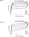
- the thermodynamic aspects of hydride formation from gaseous hydrogen are described by pressure - composition isotherms shown in Figure 1 and Figure 2 and also with other characteristics known by the skilled person in the art.
- the Figure 4 shows the logarithm of the equilibrium pressure against the reciprocal temperature. The relationship between the pressure and the temperature is exponential.
- Metal hydride compressors have been disclosed in different configurations. There exist metal hydride compressors operating with a single metal alloy as well as multi-staged compressors where different alloys are combined to allow for higher compression ratios. There are compressors operating in batch mode as well as compressors operating continuously.
- document WO 2012114229 presents a metal hydride compressor including one or several compression modules which are interconnected and comprising a gas-distributing system and a heat transfer system which includes both a hot fluid and a cold fluid system for heating and cooling, respectively.
- the compressor is thermally driven using a control system that operates the switches in the flow systems as well as the circulation pumps.
- the control system operates two compression modules simultaneously with an opposite phase in order to provide a continuous outflow of pressurized hydrogen.
- the metal hydride compressor operates at a fixed compression ratio.
- document EP 2391846 relates to a device where multiple compression modules are operated simultaneously. Furthermore, excessive heat is permanently removed from the heat sink side at a medium temperature level.
- document WO 2003006874 discloses a combined bulk storage / single stage metal hydride compressor, a hydrogen storage alloy and a hydrogen transport / distribution system.
- the device is used for bulk storage of hydrogen as well as for compression of said hydrogen to levels greater than or equal to 1500 psi (103.4 bar) at a temperature of less than or equal to 200°C.
- document DE102005004590 describes a cyclically operating metal hydride compressor, which is disclosed for the use in motor vehicles. It comprises a pressure-resistant tank filled with metal hydride and is cyclically adsorbing respectively desorbing hydrogen.
- document US6755225B1 presents a portable hydrogen fuelling station that can be refilled at low pressure, compress the hydrogen internally and deliver high-pressure hydrogen.
- document US6755225B1 presents a portable hydrogen fuelling station that can be refilled at low pressure, compress the hydrogen internally and deliver high-pressure hydrogen.
- a typical fuelling station undergoes the following steps: (1) hydrogen production by electrolysis at medium pressure (15 - 40 bar), (2) mechanical compression to 200 bar, (3) transport from the production location to the fuelling station, (4) expansion to medium pressure storage vessel (30 - 40 bar), (5) compression in several stages to 900 bar, (6) pre-cooling of the hydrogen gas to sub-zero Celsius temperatures, (7) fuelling of the hydrogen vehicle.
- Such a typical fuelling station is shown in Figure 3 .
- a primary object of the invention is to provide a simple combined storage - compression unit based on metal hydrides with a variable output pressure up to and beyond 700 bar.
- This system shall be used as the only intermediate component between the hydrogen sources, such as an electrolyser) and the end consumers such as a car, truck, boat or other.
- the instant invention relates to a combined hydrogen storage - compression module with a variable output pressure solving the above technical problem.
- the system of the present invention relates to a combined hydrogen storage-compression module with a variable output pressure
- a pressurized vessel presenting at least one inlet/outlet port in order to supply/remove hydrogen
- a hydrogen storage alloy placed within the vessel
- a heating system adapted to increase the temperature of the storage system in order to increase the pressure
- a cooling system that can remove the heat of reaction during absorption and/or reduce the pressure of the system on demand
- a thermal management system for the control of said heating and said cooling system
- a heat spreader within the pressurized vessel adapted to facilitate heat transfer within the hydrogen storage alloy
- the thermal management system by controlling the temperature of the vessel and its content, is adapted to permit a progressive ramp up of the pressure in the vessels to be filled, thereby maintain a pressure differential between the storage-compression unit and the vessel to be filled of less than or equal to 100 bar throughout the filling process.
- the hydrogen storage alloy presents an absorption plateau pressure less than or equal to 5 bar at 25°C and a desorption plateau pressure greater than or equal to 350 bar at a temperature less than or equal to 260°C.
- the hydrogen storage alloy presents a desorption plateau pressure greater than or equal to 700 bar at a temperature less than or equal to 320°C.
- the hydrogen storage system presents a hydrogen storage capacity greater than or equal to 1 kg hydrogen or, a hydrogen storage capacity greater than or equal to 5 kg hydrogen.
- the hydrogen storage alloy is comprised in the class of AB2 materials or AB5 materials.
- the heating system is adapted to enable desorption of the full hydrogen capacity of the storage system in less than or equal to 20 minute when the overpressure is greater or equal to 1 bar.
- the heating system is adapted to enable desorption of the full hydrogen capacity of the storage system in less than or equal to 5 minutes when the overpressure is greater or equal to 1 bar.
- the cooling system is adapted to enable the filling of the full hydrogen capacity of the storage system in less than or equal to 20 minutes with an overpressure of less than or equal to 1 bar.
- the pressure differential during progressive ramp up of the pressure in the vessels to be filled is maintained under 10 bar or preferably, under 1 bar.
- a second aspect of the invention relates to a combined hydrogen storage-compression system, wherein several individual modules according to the first aspect of the invention are connected in parallel or in series.
- At least two pressure containment vessels are connected and working in a sequence where one containment vessel is absorbing hydrogen while the other is desorbing hydrogen.
- heat is transferred from the colder desorbing containment vessel to the hotter absorbing containment vessel using a heat pump such as a mechanical heat pump using a compressor, a metal hydrides heat pump or any other instrument fulfilling the same goal.
- a heat pump such as a mechanical heat pump using a compressor, a metal hydrides heat pump or any other instrument fulfilling the same goal.
- the system of the present invention is safe, reliable, requires minimal maintenance and allows minimizing the number of components required from hydrogen production to refuelling.
- the system can operate with a single or multi-stage metal hydrides beds and with a batch or continuous operation.
- the delivery pressure can be above 350 bar or even above 700 bar.
- the alloy chosen has a plateau pressure less than or equal to 5 bar at 25°C. More preferably, it has a plateau pressure greater than or equal to 350 bar at 300°C.
- the instant invention has a hydrogen storage capacity of at least one time the maximal quantity of hydrogen to be withdrawn in a single step.
- the storage capacity is superior to the maximal quantity of hydrogen to be withdrawn in a single step. So several cylinders can be filled in a single batch.
- FIG. 6 shows a schematic embodiment of the present invention which relates to a combined hydrogen storage-compression unit with a variable output pressure for the filling of high-pressure hydrogen vessels, for instance in hydrogen-powered vehicles.
- the instant invention consists of a pressurized vessel, also called containment vessel, which has at least one inlet/outlet port in order to supply/remove hydrogen, a hydrogen storage alloy placed within the vessel, a heating system that can increase the temperature of the storage system in order to increase the pressure, a cooling system that can remove the heat of reaction during absorption and/or reduce the pressure of the system on demand, a thermal management system for the control of said heating and cooling system, and, a heat spreader within the containment vessel that facilitates heat transfer within the hydrogen storage alloy.
- the containment vessel can be made out of any material withstanding the maximal outlet pressure and withstanding hydrogen corrosion. Such materials can be but are not limited to certain classes of stainless steel and carbon composite materials.
- the containment vessel has at least one port for the filling/removing of hydrogen.
- the port is preferably equipped with a filter with a size smaller than the smallest particle in order to prevent particles of the storage alloy to exit the containment vessel.
- the containment vessel can be made of one single unit, or of several individual units connected in series.
- the containment vessel is either of spherical or cylindrical shape in order to spread the stresses due to high pressures.
- the connection to the gaseous hydrogen source is closed using some closing means, e.g. a mechanical or electrical valve or any other closing mean.
- the output connection of the compressor is opened with some opening / closing means, e.g. a valve or any other electrical, mechanical or electromechanical system.
- the hydrogen storage alloy used in the instant invention has a hydrogen storage capacity higher or equal to 1.2% weight.
- the hydrogen storage alloy has a storage capacity higher or equal to 1.5% or more.
- the hydrogen storage alloy absorbs hydrogen at a pressure less or equal to 50 bar at a temperature greater or equal to 5°C.
- the hydrogen storage alloy absorbs hydrogen at a pressure less or equal to 5 bar at a temperature greater or equal to 25°C.
- the material can be but is not limited to the classes AB2 and AB5 alloys. Materials with a small hysteresis ( ⁇ 2 bar) between absorption and desorption are preferable.
- the heating system is defined as any aggregate that can provide heat to the hydrogen storage material bed. It can be comprised of but is not limited to an electrical resistance heating, a heat exchanger with through flow of heating fluid or any other mean to elevate or maintain the temperature of the system on demand.
- the cooling system is defined as any aggregate that can remove heat from the hydrogen storage material bed. It can be comprised of but is not limited to a heat spreader subject to free convection outside of the containment vessel, a forced convection circuit inside or outside of the containment vessel or any other mean to reduce or maintain the temperature of the system on demand.
- the thermal management system comprises the hardware and software necessary to the control of the temperature and, thus, the control of the pressure in the hydrogen storage material.
- the temperature regulation is done with a control approach chosen in the group including PID control, MIMO control or control with any number of inputs and outputs and different sensing devices.
- the heat spreader comprises any hardware that can facilitate the heat transfer from/to the heating and/or cooling system to and within the hydrogen storage alloy. It can consist of but is not limited to extended surfaces made out of high thermal conductivity materials such as aluminium and copper or selected powder with high thermal conductivity.
- the described system allows to fill a high-pressure cylinder starting at a low pressure (e.g. ⁇ 2 bar) to the maximal pressure of the system (e.g. 700 bar).
- a low pressure e.g. ⁇ 2 bar
- the maximal pressure of the system e.g. 700 bar.
- the pressure differential between the storage-compression unit and the vessel to be filled is maintained very low ( ⁇ 100 bar, advantageously ⁇ 10 bar or ⁇ 1 bar). Thereby, no significant expansion happens during the transfer between the storage-compression unit and the vessel to be filled. Therefore, no pre-cooling of the gas is required.
- FIG. 7 In order to improve the overall energetic efficiency of the system, an arrangement is represented in figure 7 , where two or more pressure containment vessels are connected are working in a sequence is proposed. Thereby, at least one pressure containment vessel is absorbing hydrogen and at least one pressure containment vessel is desorbing hydrogen simultaneously. Thereby, heat is transferred from the vessel absorbing hydrogen to the vessel desorbing hydrogen using a heat pump or any other mean fulfilling the same technical purpose.
Landscapes
- Engineering & Computer Science (AREA)
- Mechanical Engineering (AREA)
- General Engineering & Computer Science (AREA)
- Filling Or Discharging Of Gas Storage Vessels (AREA)
Abstract
Description
- The present invention relates generally to a hydrogen infrastructure. More specifically, it relates to a combined storage - compressor unit for the fuelling of high-pressure hydrogen tanks in vehicles or other applications.
- Metal hydrides are commonly used for the storage of hydrogen under low pressures as many metals and alloys are capable of reversibly absorbing significant amounts of hydrogen. Molecular hydrogen is dissociated at the surface before absorption and two H atoms recombine to H2 upon the desorption process. The thermodynamic aspects of hydride formation from gaseous hydrogen are described by pressure - composition isotherms shown in
Figure 1 and Figure 2 and also with other characteristics known by the skilled person in the art. TheFigure 4 shows the logarithm of the equilibrium pressure against the reciprocal temperature. The relationship between the pressure and the temperature is exponential. - Metal hydride compressors have been disclosed in different configurations. There exist metal hydride compressors operating with a single metal alloy as well as multi-staged compressors where different alloys are combined to allow for higher compression ratios. There are compressors operating in batch mode as well as compressors operating continuously.
- For example, document
WO 2012114229 presents a metal hydride compressor including one or several compression modules which are interconnected and comprising a gas-distributing system and a heat transfer system which includes both a hot fluid and a cold fluid system for heating and cooling, respectively. The compressor is thermally driven using a control system that operates the switches in the flow systems as well as the circulation pumps. The control system operates two compression modules simultaneously with an opposite phase in order to provide a continuous outflow of pressurized hydrogen. - The metal hydride compressor operates at a fixed compression ratio.
- Further, document
EP 2391846 relates to a device where multiple compression modules are operated simultaneously. Furthermore, excessive heat is permanently removed from the heat sink side at a medium temperature level. - Also, document
WO 2003006874 discloses a combined bulk storage / single stage metal hydride compressor, a hydrogen storage alloy and a hydrogen transport / distribution system. The device is used for bulk storage of hydrogen as well as for compression of said hydrogen to levels greater than or equal to 1500 psi (103.4 bar) at a temperature of less than or equal to 200°C. - Finally, document
DE102005004590 describes a cyclically operating metal hydride compressor, which is disclosed for the use in motor vehicles. It comprises a pressure-resistant tank filled with metal hydride and is cyclically adsorbing respectively desorbing hydrogen. - As we can see from the above, different design and layouts for hydrogen infrastructure in general and hydrogen fuelling stations in particular have been suggested. For instance, document
US6672078B2 presents a storage system based on different metal hydrides materials with specific plateau pressures and operating temperatures. - Also, document
US6755225B1 presents a portable hydrogen fuelling station that can be refilled at low pressure, compress the hydrogen internally and deliver high-pressure hydrogen. However, there is no specification about the type of compressor to be used in that system. - However, the challenges of the existing hydrogen fuelling infrastructure are several folds. A typical fuelling station undergoes the following steps: (1) hydrogen production by electrolysis at medium pressure (15 - 40 bar), (2) mechanical compression to 200 bar, (3) transport from the production location to the fuelling station, (4) expansion to medium pressure storage vessel (30 - 40 bar), (5) compression in several stages to 900 bar, (6) pre-cooling of the hydrogen gas to sub-zero Celsius temperatures, (7) fuelling of the hydrogen vehicle. Such a typical fuelling station is shown in
Figure 3 . Through all steps, significant losses incur and high capital and operating expenditures are caused. The end price of the hydrogen delivered is heavily impacted by this fact. - In this regard, a primary object of the invention is to provide a simple combined storage - compression unit based on metal hydrides with a variable output pressure up to and beyond 700 bar. This system shall be used as the only intermediate component between the hydrogen sources, such as an electrolyser) and the end consumers such as a car, truck, boat or other.
- The instant invention relates to a combined hydrogen storage - compression module with a variable output pressure solving the above technical problem.
- The system of the present invention relates to a combined hydrogen storage-compression module with a variable output pressure comprising a pressurized vessel presenting at least one inlet/outlet port in order to supply/remove hydrogen, a hydrogen storage alloy placed within the vessel, a heating system adapted to increase the temperature of the storage system in order to increase the pressure, a cooling system that can remove the heat of reaction during absorption and/or reduce the pressure of the system on demand, a thermal management system for the control of said heating and said cooling system, and a heat spreader within the pressurized vessel adapted to facilitate heat transfer within the hydrogen storage alloy, characterized in that the thermal management system, by controlling the temperature of the vessel and its content, is adapted to permit a progressive ramp up of the pressure in the vessels to be filled, thereby maintain a pressure differential between the storage-compression unit and the vessel to be filled of less than or equal to 100 bar throughout the filling process.
- Preferably, the hydrogen storage alloy presents an absorption plateau pressure less than or equal to 5 bar at 25°C and a desorption plateau pressure greater than or equal to 350 bar at a temperature less than or equal to 260°C.
- Even more preferably, the hydrogen storage alloy presents a desorption plateau pressure greater than or equal to 700 bar at a temperature less than or equal to 320°C.
- Advantageously, the hydrogen storage system presents a hydrogen storage capacity greater than or equal to 1 kg hydrogen or, a hydrogen storage capacity greater than or equal to 5 kg hydrogen.
- According to a preferred embodiment, the hydrogen storage alloy is comprised in the class of AB2 materials or AB5 materials.
- Preferably, the heating system is adapted to enable desorption of the full hydrogen capacity of the storage system in less than or equal to 20 minute when the overpressure is greater or equal to 1 bar.
- Even more preferably, the heating system is adapted to enable desorption of the full hydrogen capacity of the storage system in less than or equal to 5 minutes when the overpressure is greater or equal to 1 bar.
- Preferably, the cooling system is adapted to enable the filling of the full hydrogen capacity of the storage system in less than or equal to 20 minutes with an overpressure of less than or equal to 1 bar.
- According to a preferred embodiment, the pressure differential during progressive ramp up of the pressure in the vessels to be filled, is maintained under 10 bar or preferably, under 1 bar.
- A second aspect of the invention relates to a combined hydrogen storage-compression system, wherein several individual modules according to the first aspect of the invention are connected in parallel or in series.
- According to a preferred embodiment, at least two pressure containment vessels are connected and working in a sequence where one containment vessel is absorbing hydrogen while the other is desorbing hydrogen.
- Preferably, heat is transferred from the colder desorbing containment vessel to the hotter absorbing containment vessel using a heat pump such as a mechanical heat pump using a compressor, a metal hydrides heat pump or any other instrument fulfilling the same goal.
- The system of the present invention is safe, reliable, requires minimal maintenance and allows minimizing the number of components required from hydrogen production to refuelling. The system can operate with a single or multi-stage metal hydrides beds and with a batch or continuous operation. The delivery pressure can be above 350 bar or even above 700 bar.
- Preferably, the alloy chosen has a plateau pressure less than or equal to 5 bar at 25°C. More preferably, it has a plateau pressure greater than or equal to 350 bar at 300°C.
- Typically, the instant invention has a hydrogen storage capacity of at least one time the maximal quantity of hydrogen to be withdrawn in a single step.
- Advantageously, the storage capacity is superior to the maximal quantity of hydrogen to be withdrawn in a single step. So several cylinders can be filled in a single batch.
- Further particular advantages and features of the invention will become more apparent from the following non-limitative description of at least one embodiment of the invention which will refer to the accompanying drawings, wherein
-
Figure 1 represents a typical pressure-composition isothermal curve (pcl) for the absorption process of hydrogen in metal hydrides -
Figure 2 represents a typical pressure-composition isothermal curve (pcl) for the desorption process of hydrogen in metal hydrides -
Figure 3 is a stylistic depiction of the current typical process for the filling of hydrogen vehicles -
Figure 4 is a Van't Hoff plot of an AB5 alloy suitable for the instant invention -
Figure 5 is shows two pressure-composition isothermal curves (pcI) together with a typical working cycle of the present invention -
Figure 6 is a stylistic depiction of a possible technical implementation of the instant invention -
Figure 7 is a stylistic depiction of a possible technical implementation where heat is transferred from the cold reservoir to the hot reservoir using a heat pump - The present detailed description is intended to illustrate the invention in a non-limitative manner since any feature of an embodiment may be combined with any other feature of a different embodiment in an advantageous manner.
-
Figure 6 shows a schematic embodiment of the present invention which relates to a combined hydrogen storage-compression unit with a variable output pressure for the filling of high-pressure hydrogen vessels, for instance in hydrogen-powered vehicles. The instant invention consists of a pressurized vessel, also called containment vessel, which has at least one inlet/outlet port in order to supply/remove hydrogen, a hydrogen storage alloy placed within the vessel, a heating system that can increase the temperature of the storage system in order to increase the pressure, a cooling system that can remove the heat of reaction during absorption and/or reduce the pressure of the system on demand, a thermal management system for the control of said heating and cooling system, and, a heat spreader within the containment vessel that facilitates heat transfer within the hydrogen storage alloy. - The containment vessel can be made out of any material withstanding the maximal outlet pressure and withstanding hydrogen corrosion. Such materials can be but are not limited to certain classes of stainless steel and carbon composite materials. The containment vessel has at least one port for the filling/removing of hydrogen. The port is preferably equipped with a filter with a size smaller than the smallest particle in order to prevent particles of the storage alloy to exit the containment vessel. The containment vessel can be made of one single unit, or of several individual units connected in series. Advantageously, the containment vessel is either of spherical or cylindrical shape in order to spread the stresses due to high pressures. According to a preferred embodiment of the present invention, the connection to the gaseous hydrogen source is closed using some closing means, e.g. a mechanical or electrical valve or any other closing mean. Advantageously, the output connection of the compressor is opened with some opening / closing means, e.g. a valve or any other electrical, mechanical or electromechanical system.
- The hydrogen storage alloy used in the instant invention has a hydrogen storage capacity higher or equal to 1.2% weight. Advantageously, the hydrogen storage alloy has a storage capacity higher or equal to 1.5% or more. The hydrogen storage alloy absorbs hydrogen at a pressure less or equal to 50 bar at a temperature greater or equal to 5°C. Advantageously, the hydrogen storage alloy absorbs hydrogen at a pressure less or equal to 5 bar at a temperature greater or equal to 25°C. The material can be but is not limited to the classes AB2 and AB5 alloys. Materials with a small hysteresis (< 2 bar) between absorption and desorption are preferable.
- The heating system is defined as any aggregate that can provide heat to the hydrogen storage material bed. It can be comprised of but is not limited to an electrical resistance heating, a heat exchanger with through flow of heating fluid or any other mean to elevate or maintain the temperature of the system on demand.
- The cooling system is defined as any aggregate that can remove heat from the hydrogen storage material bed. It can be comprised of but is not limited to a heat spreader subject to free convection outside of the containment vessel, a forced convection circuit inside or outside of the containment vessel or any other mean to reduce or maintain the temperature of the system on demand.
- The thermal management system comprises the hardware and software necessary to the control of the temperature and, thus, the control of the pressure in the hydrogen storage material. Advantageously, the temperature regulation is done with a control approach chosen in the group including PID control, MIMO control or control with any number of inputs and outputs and different sensing devices.
- The heat spreader comprises any hardware that can facilitate the heat transfer from/to the heating and/or cooling system to and within the hydrogen storage alloy. It can consist of but is not limited to extended surfaces made out of high thermal conductivity materials such as aluminium and copper or selected powder with high thermal conductivity.
- The described system allows to fill a high-pressure cylinder starting at a low pressure (e.g. < 2 bar) to the maximal pressure of the system (e.g. 700 bar). Throughout the process, the pressure differential between the storage-compression unit and the vessel to be filled is maintained very low (< 100 bar, advantageously < 10 bar or < 1 bar). Thereby, no significant expansion happens during the transfer between the storage-compression unit and the vessel to be filled. Therefore, no pre-cooling of the gas is required.
- In order to improve the overall energetic efficiency of the system, an arrangement is represented in
figure 7 , where two or more pressure containment vessels are connected are working in a sequence is proposed. Thereby, at least one pressure containment vessel is absorbing hydrogen and at least one pressure containment vessel is desorbing hydrogen simultaneously. Thereby, heat is transferred from the vessel absorbing hydrogen to the vessel desorbing hydrogen using a heat pump or any other mean fulfilling the same technical purpose. - While the embodiments have been described in conjunction with a number of embodiments, it is evident that many alternatives, modifications and variations would be or are apparent to those of ordinary skill in the applicable arts. Accordingly, this disclosure is intended to embrace all such alternatives, modifications, equivalents and variations that are within the scope of this disclosure. This for example is particularly the case regarding the exact temperature used, the material used, the monitoring system, the number of stages, the temperature sensor and all the different apparatuses, which can be used in conjunction with the present invention.
Claims (12)
- A combined hydrogen storage-compression module with a variable output pressure comprising
a pressurized vessel presenting at least one inlet/outlet port in order to supply/remove hydrogen,
a hydrogen storage alloy placed within the vessel,
a heating system adapted to increase the temperature of the storage system in order to increase the pressure,
a cooling system that can remove the heat of reaction during absorption and/or reduce the pressure of the system on demand,
a thermal management system for the control of said heating and said cooling system, and
a heat spreader within the pressurized vessel adapted to facilitate heat transfer within the hydrogen storage alloy,
characterized in that the thermal management system, by controlling the temperature of the vessel and its content, is adapted to permit a progressive ramp up of the pressure in the vessels to be filled, thereby maintain a pressure differential between the storage-compression unit and the vessel to be filled of less than or equal to 100 bar throughout the filling process. - The combined hydrogen storage-compression module according to claim 1, wherein the hydrogen storage alloy presents an absorption plateau pressure less than or equal to 5 bar at 25°C and a desorption plateau pressure greater than or equal to 350 bar at a temperature less than or equal to 260°C.
- The combined hydrogen storage-compression module according to claim 1 or 2, wherein the hydrogen storage alloy presents a desorption plateau pressure greater than or equal to 700 bar at a temperature less than or equal to 320°C.
- The combined hydrogen storage-compression module according to any one of claims 1 to 3, wherein the hydrogen storage alloy presents a hydrogen storage capacity greater than or equal to 1 kg hydrogen or, a hydrogen storage capacity greater than or equal to 5 kg hydrogen.
- The combined hydrogen storage-compression module according to any one of claims 1 to 4, wherein the hydrogen storage alloy is comprised in the class of AB2 materials or AB5 materials.
- The combined hydrogen storage-compression module according to any one of claims 1 to 5, wherein the heating system is adapted to enable the desorption of the full hydrogen capacity of the storage system in less than or equal to five minute when the overpressure is greater or equal to 1 bar.
- The combined hydrogen storage-compression module according to any one of claims 1 to 6, wherein the heating system is adapted to enable the desorption of the full hydrogen capacity of the storage system in less than or equal to 20 minutes when the overpressure is greater or equal to 1 bar.
- The combined hydrogen storage-compression module according to any one of claims 1 to 7, wherein the cooling system is adapted to enable the filling of the full hydrogen capacity of the storage system in less than or equal to five minutes with an overpressure of less than or equal to 1 bar.
- The combined hydrogen storage-compression module according to any one of claims 1 to 8, wherein the pressure differential progressive ramp up of the pressure in the vessels to be filled, is maintained under 10 bar or preferably, under 1 bar.
- A combined hydrogen storage-compression system, wherein several individual modules according to any one of claims 1 to 3 are connected in parallel or in series.
- The combined hydrogen storage-compression system of 10, where at least two pressure containment vessels are connected and working in a sequence where one containment vessel is absorbing hydrogen while the other is desorbing hydrogen.
- The combined hydrogen storage-compression system of 11, wherein, heat is transferred from the colder desorbing containment vessel to the hotter absorbing containment vessel using a heat pump.
Priority Applications (5)
| Application Number | Priority Date | Filing Date | Title |
|---|---|---|---|
| EP19167968.7A EP3722653A1 (en) | 2019-04-08 | 2019-04-08 | Combined hydrogen storage - compression system for the filling of high pressure hydrogen tanks |
| KR1020217036218A KR102723860B1 (en) | 2019-04-08 | 2020-03-24 | Integrated hydrogen storage-compression system for filling high-pressure hydrogen tanks |
| EP20715792.6A EP3953637A1 (en) | 2019-04-08 | 2020-03-24 | Combined hydrogen storage - compression system for the filling of high pressure hydrogen tanks |
| US17/601,824 US12104751B2 (en) | 2019-04-08 | 2020-03-24 | Combined hydrogen storage - compression system for the filling of high pressure hydrogen tanks |
| PCT/EP2020/058227 WO2020207790A1 (en) | 2019-04-08 | 2020-03-24 | Combined hydrogen storage - compression system for the filling of high pressure hydrogen tanks |
Applications Claiming Priority (1)
| Application Number | Priority Date | Filing Date | Title |
|---|---|---|---|
| EP19167968.7A EP3722653A1 (en) | 2019-04-08 | 2019-04-08 | Combined hydrogen storage - compression system for the filling of high pressure hydrogen tanks |
Publications (1)
| Publication Number | Publication Date |
|---|---|
| EP3722653A1 true EP3722653A1 (en) | 2020-10-14 |
Family
ID=66102571
Family Applications (2)
| Application Number | Title | Priority Date | Filing Date |
|---|---|---|---|
| EP19167968.7A Withdrawn EP3722653A1 (en) | 2019-04-08 | 2019-04-08 | Combined hydrogen storage - compression system for the filling of high pressure hydrogen tanks |
| EP20715792.6A Pending EP3953637A1 (en) | 2019-04-08 | 2020-03-24 | Combined hydrogen storage - compression system for the filling of high pressure hydrogen tanks |
Family Applications After (1)
| Application Number | Title | Priority Date | Filing Date |
|---|---|---|---|
| EP20715792.6A Pending EP3953637A1 (en) | 2019-04-08 | 2020-03-24 | Combined hydrogen storage - compression system for the filling of high pressure hydrogen tanks |
Country Status (4)
| Country | Link |
|---|---|
| US (1) | US12104751B2 (en) |
| EP (2) | EP3722653A1 (en) |
| KR (1) | KR102723860B1 (en) |
| WO (1) | WO2020207790A1 (en) |
Cited By (1)
| Publication number | Priority date | Publication date | Assignee | Title |
|---|---|---|---|---|
| DE102024119145A1 (en) * | 2024-07-05 | 2026-01-08 | Energie mit Plan GmbH | Energy system and methods for operating an energy system |
Families Citing this family (4)
| Publication number | Priority date | Publication date | Assignee | Title |
|---|---|---|---|---|
| US12422099B1 (en) * | 2022-10-17 | 2025-09-23 | National Technology & Engineering Solutions Of Sandia, Llc. | Hydrogen compression and storage systems |
| WO2024152079A1 (en) * | 2023-01-21 | 2024-07-25 | Great Southern Motor Company Pty. Ltd. | Pressure device |
| DE102024120662B3 (en) | 2024-07-19 | 2025-11-13 | Messer Schweiz Ag | Device and method for compressing a medium |
| CN119900923B (en) * | 2025-03-26 | 2025-06-20 | 山东国信工业科技股份有限公司 | Intelligent hydrogen storage management system |
Citations (7)
| Publication number | Priority date | Publication date | Assignee | Title |
|---|---|---|---|---|
| WO2001069144A2 (en) * | 2000-03-17 | 2001-09-20 | Stuart Energy Systems Corporation | Hydrogen compressor |
| WO2003006874A1 (en) | 2001-07-10 | 2003-01-23 | Energy Conversion Devices, Inc. | Single stage metal hydride compressor |
| US6755225B1 (en) | 2003-01-24 | 2004-06-29 | Quantum Fuel Systems Technologies Worldwide, Inc. | Transportable hydrogen refueling station |
| DE102005004590A1 (en) | 2005-02-01 | 2006-08-10 | Bayerische Motoren Werke Ag | Device for increasing the pressure of hydrogen |
| EP2391846A1 (en) | 2009-01-30 | 2011-12-07 | Institutt For Energiteknikk | Continuously-operated metal hydride hydrogen compressor, and method of operating the same |
| WO2012114229A1 (en) | 2011-02-21 | 2012-08-30 | Eskom Holdings Ltd | Metal hydride hydrogen compressor |
| WO2016147134A1 (en) * | 2015-03-18 | 2016-09-22 | University Of The Western Cape | Multistage metal hydride hydrogen compressor |
Family Cites Families (1)
| Publication number | Priority date | Publication date | Assignee | Title |
|---|---|---|---|---|
| DE3809680A1 (en) * | 1988-03-17 | 1989-09-28 | Mannesmann Ag | PLANT FOR COMPRESSING HYDROGEN GAS |
-
2019
- 2019-04-08 EP EP19167968.7A patent/EP3722653A1/en not_active Withdrawn
-
2020
- 2020-03-24 US US17/601,824 patent/US12104751B2/en active Active
- 2020-03-24 EP EP20715792.6A patent/EP3953637A1/en active Pending
- 2020-03-24 KR KR1020217036218A patent/KR102723860B1/en active Active
- 2020-03-24 WO PCT/EP2020/058227 patent/WO2020207790A1/en not_active Ceased
Patent Citations (8)
| Publication number | Priority date | Publication date | Assignee | Title |
|---|---|---|---|---|
| US6672078B2 (en) | 1999-11-06 | 2004-01-06 | Energy Conversion Devices, Inc. | Hydrogen infrastructure, a combined bulk hydrogen storage/single stage metal hydride hydrogen compressor therefor and alloys for use therein |
| WO2001069144A2 (en) * | 2000-03-17 | 2001-09-20 | Stuart Energy Systems Corporation | Hydrogen compressor |
| WO2003006874A1 (en) | 2001-07-10 | 2003-01-23 | Energy Conversion Devices, Inc. | Single stage metal hydride compressor |
| US6755225B1 (en) | 2003-01-24 | 2004-06-29 | Quantum Fuel Systems Technologies Worldwide, Inc. | Transportable hydrogen refueling station |
| DE102005004590A1 (en) | 2005-02-01 | 2006-08-10 | Bayerische Motoren Werke Ag | Device for increasing the pressure of hydrogen |
| EP2391846A1 (en) | 2009-01-30 | 2011-12-07 | Institutt For Energiteknikk | Continuously-operated metal hydride hydrogen compressor, and method of operating the same |
| WO2012114229A1 (en) | 2011-02-21 | 2012-08-30 | Eskom Holdings Ltd | Metal hydride hydrogen compressor |
| WO2016147134A1 (en) * | 2015-03-18 | 2016-09-22 | University Of The Western Cape | Multistage metal hydride hydrogen compressor |
Cited By (1)
| Publication number | Priority date | Publication date | Assignee | Title |
|---|---|---|---|---|
| DE102024119145A1 (en) * | 2024-07-05 | 2026-01-08 | Energie mit Plan GmbH | Energy system and methods for operating an energy system |
Also Published As
| Publication number | Publication date |
|---|---|
| KR20210145276A (en) | 2021-12-01 |
| US12104751B2 (en) | 2024-10-01 |
| US20220205592A1 (en) | 2022-06-30 |
| KR102723860B1 (en) | 2024-10-29 |
| EP3953637A1 (en) | 2022-02-16 |
| WO2020207790A1 (en) | 2020-10-15 |
Similar Documents
| Publication | Publication Date | Title |
|---|---|---|
| US12104751B2 (en) | Combined hydrogen storage - compression system for the filling of high pressure hydrogen tanks | |
| Yanxing et al. | Thermodynamics analysis of hydrogen storage based on compressed gaseous hydrogen, liquid hydrogen and cryo-compressed hydrogen | |
| US6834508B2 (en) | Hydrogen storage and supply system | |
| Laurencelle et al. | Experimental study on a metal hydride based hydrogen compressor | |
| US11873221B1 (en) | Integrated system and method for hydrogen purification, storage and pressurization | |
| WO2012114229A1 (en) | Metal hydride hydrogen compressor | |
| KR20210149181A (en) | hydrogen storage system | |
| Barale et al. | A metal hydride compressor for a small scale H2 refuelling station | |
| Goshome et al. | Demonstration of a single-stage metal hydride hydrogen compressor composed of BCC V40TiCr alloy | |
| Gambini et al. | High temperature metal hydrides for energy systems Part B: Comparison between high and low temperature metal hydride reservoirs | |
| NO330286B1 (en) | Continuously operated hydrogen compressor and method of operation thereof | |
| Gupta et al. | Characterisation of La0. 9Ce0. 1Ni5 alloy for the development of single‐stage thermally driven sorption hydrogen compressor | |
| US11440796B2 (en) | Metal hydride compressor control device and method | |
| EP1634016B1 (en) | Storage of h2 by absorption in liquid nitrogen | |
| US11289717B2 (en) | System and method for heat management of high-temperature systems | |
| Gkanas et al. | Metal hydride hydrogen compression systems–materials, applications and numerical analysis | |
| US9599373B2 (en) | Hydrogen storage heat pump and hydrogen storage heat pump system | |
| CN110573790A (en) | Hydrogen storage and supply system | |
| US12372205B2 (en) | Hydrogen storage and compression system | |
| US20250305493A1 (en) | Gas compression system and method for recovering hydrogen | |
| JP2025517339A5 (en) | ||
| Ahluwalia et al. | 2010 DOE Hydrogen Program Review Washington, DC June 8-11, 2010 | |
| CA2531380A1 (en) | Novel disproportionation resistant hydrogen storage alloys | |
| Schwarz | Department of Chemical Engineering and Materials Science and. Laboratory for Advanced Storage Systems for Hydrogen Syracuse University | |
| Wu et al. | Metal Hydride Hydrogen Storage and Compression System for Hydrogen Refueling Station |
Legal Events
| Date | Code | Title | Description |
|---|---|---|---|
| PUAI | Public reference made under article 153(3) epc to a published international application that has entered the european phase |
Free format text: ORIGINAL CODE: 0009012 |
|
| STAA | Information on the status of an ep patent application or granted ep patent |
Free format text: STATUS: THE APPLICATION HAS BEEN PUBLISHED |
|
| AK | Designated contracting states |
Kind code of ref document: A1 Designated state(s): AL AT BE BG CH CY CZ DE DK EE ES FI FR GB GR HR HU IE IS IT LI LT LU LV MC MK MT NL NO PL PT RO RS SE SI SK SM TR |
|
| AX | Request for extension of the european patent |
Extension state: BA ME |
|
| RAP1 | Party data changed (applicant data changed or rights of an application transferred) |
Owner name: ECOLE POLYTECHNIQUE FEDERALE DE LAUSANNE (EPFL) |
|
| STAA | Information on the status of an ep patent application or granted ep patent |
Free format text: STATUS: THE APPLICATION IS DEEMED TO BE WITHDRAWN |
|
| 18D | Application deemed to be withdrawn |
Effective date: 20210415 |