EP3722583B1 - Turbine exhaust case mixer - Google Patents
Turbine exhaust case mixer Download PDFInfo
- Publication number
- EP3722583B1 EP3722583B1 EP20168833.0A EP20168833A EP3722583B1 EP 3722583 B1 EP3722583 B1 EP 3722583B1 EP 20168833 A EP20168833 A EP 20168833A EP 3722583 B1 EP3722583 B1 EP 3722583B1
- Authority
- EP
- European Patent Office
- Prior art keywords
- strut
- mixer
- tec
- struts
- shroud
- Prior art date
- Legal status (The legal status is an assumption and is not a legal conclusion. Google has not performed a legal analysis and makes no representation as to the accuracy of the status listed.)
- Active
Links
Images



Classifications
-
- F—MECHANICAL ENGINEERING; LIGHTING; HEATING; WEAPONS; BLASTING
- F01—MACHINES OR ENGINES IN GENERAL; ENGINE PLANTS IN GENERAL; STEAM ENGINES
- F01D—NON-POSITIVE DISPLACEMENT MACHINES OR ENGINES, e.g. STEAM TURBINES
- F01D25/00—Component parts, details, or accessories, not provided for in, or of interest apart from, other groups
- F01D25/30—Exhaust heads, chambers, or the like
-
- F—MECHANICAL ENGINEERING; LIGHTING; HEATING; WEAPONS; BLASTING
- F02—COMBUSTION ENGINES; HOT-GAS OR COMBUSTION-PRODUCT ENGINE PLANTS
- F02K—JET-PROPULSION PLANTS
- F02K1/00—Plants characterised by the form or arrangement of the jet pipe or nozzle; Jet pipes or nozzles peculiar thereto
- F02K1/38—Introducing air inside the jet
- F02K1/386—Introducing air inside the jet mixing devices in the jet pipe, e.g. for mixing primary and secondary flow
-
- F—MECHANICAL ENGINEERING; LIGHTING; HEATING; WEAPONS; BLASTING
- F02—COMBUSTION ENGINES; HOT-GAS OR COMBUSTION-PRODUCT ENGINE PLANTS
- F02K—JET-PROPULSION PLANTS
- F02K1/00—Plants characterised by the form or arrangement of the jet pipe or nozzle; Jet pipes or nozzles peculiar thereto
- F02K1/46—Nozzles having means for adding air to the jet or for augmenting the mixing region between the jet and the ambient air, e.g. for silencing
- F02K1/48—Corrugated nozzles
-
- F—MECHANICAL ENGINEERING; LIGHTING; HEATING; WEAPONS; BLASTING
- F05—INDEXING SCHEMES RELATING TO ENGINES OR PUMPS IN VARIOUS SUBCLASSES OF CLASSES F01-F04
- F05D—INDEXING SCHEME FOR ASPECTS RELATING TO NON-POSITIVE-DISPLACEMENT MACHINES OR ENGINES, GAS-TURBINES OR JET-PROPULSION PLANTS
- F05D2260/00—Function
- F05D2260/94—Functionality given by mechanical stress related aspects such as low cycle fatigue [LCF] of high cycle fatigue [HCF]
- F05D2260/941—Functionality given by mechanical stress related aspects such as low cycle fatigue [LCF] of high cycle fatigue [HCF] particularly aimed at mechanical or thermal stress reduction
-
- Y—GENERAL TAGGING OF NEW TECHNOLOGICAL DEVELOPMENTS; GENERAL TAGGING OF CROSS-SECTIONAL TECHNOLOGIES SPANNING OVER SEVERAL SECTIONS OF THE IPC; TECHNICAL SUBJECTS COVERED BY FORMER USPC CROSS-REFERENCE ART COLLECTIONS [XRACs] AND DIGESTS
- Y02—TECHNOLOGIES OR APPLICATIONS FOR MITIGATION OR ADAPTATION AGAINST CLIMATE CHANGE
- Y02T—CLIMATE CHANGE MITIGATION TECHNOLOGIES RELATED TO TRANSPORTATION
- Y02T50/00—Aeronautics or air transport
- Y02T50/60—Efficient propulsion technologies, e.g. for aircraft
Definitions
- the application relates to exhaust mixers for turbofan aircraft engines.
- bladed fans In order to increase the effective thrust of turbojet engines, bladed fans have been added to a turbine driven shaft thereof to affect the flow of a quantity of atmospheric air through an annular bypass duct surrounding the turbojet. Hot gases exhausted from the engine core and the bypass airstream are mixed together before expulsion through a single nozzle. In order to perform the mixing function, mixers have been attached to the downstream end of a shroud of the turbine exhaust case (TEC).
- TEC turbine exhaust case
- a TEC mixer may include a plurality of struts that attach the TEC mixer to the aircraft engine such that the exhausted gases are mixed with bypass airflow in order to reduce hotspots in at least part of the exhaust gas airflow.
- TEC mixers experience various different stresses.
- prior art technologies identify "potential weak spots" in various parts of the TEC mixers and add material to the "potential weak spots” to strengthen them.
- Such prior art methods and the resulting TEC mixers are suitable for their intended purposes. Nevertheless, there is room to improve the prior art.
- the present invention provides a turbine exhaust case mixer as set forth in claim 1, and a turbine exhaust case mixer as set forth in claim 12.
- FIG. 1 illustrates a turbofan aircraft engine 8 which includes a nacelle 10, a core casing 13, a low pressure spool assembly 12 which includes a fan assembly 14, a low pressure compressor assembly 16 coupled to a low pressure turbine assembly 18, and a high pressure spool assembly seen generally at 20 which includes a high pressure compressor assembly 22 coupled to a high pressure turbine assembly 24.
- the core casing 13 surrounds the low and high pressure spool assemblies 12, 20 in order to define a main fluid path (not numbered) therethrough.
- a combustion chamber 26 in which a combustion process produces combustion gases that power the high and low turbine pressure assemblies 24, 18.
- the core casing 13 extends from a front portion of the aircraft engine 8 toward a hub / inner shroud 28 disposed at a rear of the aircraft engine 8 downstream of the high pressure turbine assembly 24.
- the aircraft engine 8 further includes a turbine exhaust case (TEC) mixer 30 which is disposed downstream of the high pressure turbine assembly 24.
- the hub / inner shroud 28 may be circular in shape, for example, and may have an annular body.
- the TEC mixer 30 surrounds the hub / inner shroud 28 to form an annular exhaust gas duct 32 disposed radially therebetween. Hot exhaust gases 13EX that are discharged from the pressure turbine assemblies 18, 24 exit the main fluid path of the aircraft engine 8 and pass through the exhaust gas duct 32.
- a bypass airstream 10BP driven by the fan assembly 14 flows through an annular bypass duct 15 defined radially between the nacelle 10 and the core casing 13. At least part of the bypass airstream 10BP exits the aircraft engine 8 by passing through, or along, the TEC mixer 30. At least part of the bypass airstream 10BP and at least part of the hot exhaust gases 13EX mix at least after exiting the aircraft engine 8.
- the hub / inner shroud 28 and the TEC mixer 30 may define a central axis 34 that is substantially collinear with a central rotation axis of the aircraft engine 8, or parallel or quasi parallel to the central rotation axis.
- upstream and downstream are used to refer to the direction of a fluid flow passing through the main fluid path of an aircraft engine.
- axial is used with respect to the central axis 34 of the aircraft engine 8.
- forward and “rearward” are used with respect to the direction of flight.
- the TEC mixer 30 includes an annular wall 31 around the central axis 34.
- the annular wall 31 of the TEC mixer 30 defines the exhaust gas duct 32.
- the annular wall 31 is distinct from the core casing 13, and from the shroud(s) and other elements of the core casing 13.
- the annular wall 31 could be part of the core casing 13 and/or other element(s) of the aircraft engine 8 for example.
- the annular wall 31 is shaped for directing at least part of the bypass airstream 10BP that exits the bypass air duct 15.
- the shape of the annular wall 31 of the TEC mixer 30 may in at least some embodiments establish a vortex system downstream of the TEC mixer 30 to encourage mixing between the bypass airstream 10BP and the turbine exhaust gases 13EX at least downstream of the TEC mixer 30 during operation of the aircraft engine 8.
- the TEC mixer 30 includes a plurality of struts 36 that are circumferentially distributed and spaced apart along an inner surface of the annular wall 31.
- the struts 36 have leading and trailing edges (36L, 36T respectively) and extend in a chord-wise direction along at least a part of an axial length of the annular wall 31, for example between an upstream end and a downstream end of the annular wall 31, or at other points.
- the struts 36 are distributed circumferentially around the hub / inner shroud 28, in this example, at equal circumferential distances, though the skilled reader will appreciate that the struts 36 spacing could be different.
- the struts 36 extend generally radially. Any suitable arrangement for struts 36 may be employed, however.
- the struts 36 extend in a span-wise direction across the annular exhaust gas duct 32 and connect the TEC mixer 30 to the inner shroud, and more particularly in this embodiment to the hub / inner shroud 28. More particularly, in the present embodiment, the struts 36 extend from the annular wall 31 of the TEC mixer 30 to the hub / inner shroud 28.
- the struts 36 may be shaped, positioned, oriented and sized so as to at least in part deswirl the exhaust gases 13EX that pass through the exhaust gas duct 32.
- one or more of the struts 36 may be structural in nature and need not provide a deswirling action.
- One or more of the struts 36 may be at least in part disposed outside of the exhaust gas duct 32 and/or may connect to a different part of the aircraft engine 8 than the hub / inner shroud 28.
- struts 36 of the present embodiment is shown in more detail.
- the rest of the struts 36 are similar to the strut 36 shown in Fig. 2 .
- the rest of the struts 36 are therefore not described in detail. It is contemplated that some of the struts 36 could have a different shape than the rest of the struts 36.
- the strut 36 includes a leading surface 36L oriented forward, and a trailing surface 36T oriented rearward.
- edge surface is used for 36L and 36T, but they may also be referred to as leading edge 36L and trailing edge 36T, or even leading edge surface 36L and trailing edge surface 36T.
- the strut 36 may also include an shroud-strut interface 36IN, for connection to the hub / inner shroud 28, and an annular-wall-to-strut interface 36OUT for connection to the annular wall 31.
- the leading surface 36L may extend between a front portion of the shroud-strut interface 36IN and a front portion of the annular-wall-to-strut interface 36OUT and may face into the stream of exhaust gases 13EX.
- the trailing surface 36T may extend between a rear portion of the shroud-strut interface 36IN and a rear portion of the annular-wall-to-strut interface 36OUT.
- the shroud-strut interface 36IN is connected along its length to the hub / inner shroud 28 by being welded to a corresponding portion of the hub / inner shroud 28. It is contemplated that a different connecting arrangement could be used to connect the shroud-strut interface 36IN, directly or indirectly, to the hub / inner shroud 28 or other part of the aircraft engine 8, for example, such as brazing, soldering, casting.
- the annular-wall-to-strut interface 36OUT is connected along its length to the annular wall 31. It is contemplated that any suitable connecting arrangement could be used to connect the annular-wall-to-strut interface 36OUT to the annular wall 31, such as those mentioned above for the shroud-strut interface 36IN.
- the leading surface 36L of the strut 36 is defined by a cavity (not numbered), and the trailing surface 36T is defined by a cavity (not numbered).
- the cavity defining the leading surface 36L of the strut 36 is an inward cavity extending in a rearward direction from a straight radial line 38F extending from a forward tip of the shroud-strut interface 361N to a forward tip of the annular-wall-to-strut interface 36OUT.
- the cavity defining the trailing surface 36T is an inward cavity extending in a forward direction from a straight radial line 38R extending from a rearward tip of the shroud-strut interface 361N to a rearward tip of the annular-wall-to-strut interface 36OUT.
- boundaries of each of the two cavities are spaced from the shroud-strut interface 361N and the annular-wall-to-strut interface 36OUT, and hence also from the axial ends of the strut 36. It is contemplated that in some embodiments, at least one of the cavities could extend to one or both of the shroud-strut interface 36IN and the annular-wall-to-strut interface 36OUT.
- each of the cavities includes a curved portion proximate to the shroud-strut interface 361N.
- Each of the cavities also includes a curved portion proximate to the annular-wall-to-strut interface 36OUT.
- a tangent to a part of each of the curved portions defines an angle ⁇ 1 , ⁇ 2 , ⁇ 3 , ⁇ 4 , respectively, with a tangent to a part of a respective one of the shroud-strut interface 36IN and the annular-wall-to-strut interface 36OUT.
- the spacing of the boundaries of the cavities from the inner and annular-wall-to-strut interfaces 36IN, 36OUT forms a stepped structure 40 at each corner of the strut 36. It is contemplated that one or more of the struts 36 could have fewer than the four stepped structures 40 and/or could have none of the stepped structures 40.
- angles ⁇ 1 , ⁇ 2 , ⁇ 3 , ⁇ 4 provide a taper that helps increase a flexibility of the struts 36 at least at the extremities of the shroud-strut interface 36IN and the annular-wall-to-strut interface 36OUT. In at least some embodiments and/or applications, the increased flexibility helps reduce peak stresses along at least parts of the shroud-strut interfaces 36IN and the annular-wall-to-strut interfaces 36OUT of the struts 36. In the present embodiment, the angles ⁇ 1 , ⁇ 2 , ⁇ 3 , ⁇ 4 are different, but are all less than fifteen degrees.
- the angles ⁇ 1 , ⁇ 2 , ⁇ 3 , ⁇ 4 are different, but are all less than thirty degrees. Further in the present embodiment, the angles ⁇ 3 , ⁇ 4 are each less than five degrees. In some embodiments, the angles ⁇ 1 , ⁇ 2 , ⁇ 3 , ⁇ 4 are each less than thirty degrees. In an embodiment, the angles ⁇ 1 , ⁇ 2 , ⁇ 3 , ⁇ 4 range from 0 to 15 degrees. In another embodiment, the angles ⁇ 1 , ⁇ 2 , ⁇ 3 , ⁇ 4 range from 0 to 30 degrees.
- one or both of the cavities could include only one of the respective curved portions.
- a first step 40A of each of the stepped structures 40 is connected to a respective one of the annular wall 31 and the hub / inner shroud 28, and a second step 40B of each of the stepped structures 40 is disposed between the first step 40A and a generally middle portion 36MS ( Fig. 2 ) or mid-span region of the strut 36.
- the first step 40A is wider than the second step 40B, and may be said to have a larger footprint defining the shroud-strut interface 36IN.
- the term "mid-span” is intended to refer to any portion of the span away from the ends of the strut, such as between about 30-70% of the span.
- the (radially inner) first step 40A is defined by planar surfaces and fillets between the planar surfaces and the hub/inner shroud 28 and/or a second step 40B, with the planar surfaces being angled relative to a plane tangent to a part of an outer surface of the hub / inner shroud 28 to which the first step 40A connects.
- each of those first steps 40A is similarly defined by planar surfaces and fillets, with the planar surfaces being angled relative to a plane tangent to a part of a surface of the annular wall 31 to that first step 40A connects.
- each of the planar surfaces of the (inner) first step 40A defines an acute angle 42 with a plane tangent to a part of the outer surface of the hub / inner shroud 28 to which the first step 40A connects, and an obtuse angle 44 with a contiguous/adjacent planar surface of the corresponding second step 40B.
- the (outer) first steps 40A of the strut 36 define an acute angle with the outer surface of the hub / inner shroud 28 to which they connect and an obtuse angle 44 with a contiguous/adjacent surface of each corresponding second step 40B.
- the second step 40B is disposed radially closer to the middle portion 36MS of the strut 36 than the first step 40A.
- the second step 40B includes a planar surface 40PS disposed between the curved portion and the first step 40A.
- the planar surface 40PS defines the angle ⁇ 2 ( Fig. 2 ) with a corresponding part of the shroud-strut interface 361N.
- a projection of the planar surface 40PS would intersect a projection of shroud-strut interface 36IN and these projections would define the angle ⁇ 2 therebetween.
- this feature provides a smooth transition between the planar surface 40PS and the contiguous corresponding curved portion of the strut 36.
- the second step 40B may further include convex portion 40X disposed between the planar surface 40PS and the first step 40A.
- the convex portion 40X is arcuate, but it is contemplated that other shapes could also be used.
- the convex portion 40X provides a smooth transition between the first step 40A and the second step 40B.
- the planar surface 40PS provides a smooth transition between the convex portion 40X and the rest of the corresponding cavity in the strut 36. It is contemplated that the surface 40PS could be non-planar.
- Such smooth transitions may help reduce a peak stress in the strut 36 in at least at one point when the TEC mixer 30 is in use, and hence may help improve an expected life of the struts 36 in at least some applications of the TEC mixer 30. It is contemplated that one or more of the stepped structures 40 could have a greater or a smaller number of the smooth transitions. It is also contemplated that the particular characteristics of the smooth transitions could be selected to suit each particular embodiment and application of the TEC mixer 30.
- each of the stepped structures 40 may help reduce peak stresses in the strut 36 along the respective ones of the inner and annular-wall-to-strut interfaces 36IN, 36OUT.
- the stepped structure 40 shown in Fig. 3 for example, it has been found that the stepped structures 40 may help reduce peak stresses in the strut 36 at least in a transverse direction 46 out of plane with the strut 36 and in a longitudinal direction 48 along the shroud-strut interface 361N. Therefore, the stepped structure 40 shown in Fig. 3 is a non-limiting embodiment of a means for reducing at least one stress in at least some of the struts 36.
- the means is a means for reducing at least one stress in at least the strut having the means.
- a TEC mixer 30 for an aircraft engine 8 configured for mixing concentric core and bypass gas flows via a lobed mixer (not separately numbered, shown schematically in Fig. 1 ), the TEC mixer 30 comprising struts 36 extending in a span-wise direction from mixer lobes (not separately numbered, shown schematically in Fig. 1 ) to an inner shroud 28 across the core gas flow, each strut 36 having leading and trailing edges 36L, 36T separated by an axial chord, the strut 26 being axially narrower in the chord at a mid-span portion of the strut 36 than at an interface of the strut 36 and the inner shroud 28.
- the method 100 may be executed at a server 80 that includes a processor 82 and a non-transient memory 84 communicatively coupled to the processor 82, the non-transient memory 84 storing processor-executable instructions which, when executed by the processor 82 cause the server 80 to execute the functionality described in this document.
- the server 80 could be a single physical computer, such as a desktop or a laptop. In other embodiments, the server 80 could be a distributed server and/or a cloud-based server. In the present embodiment, the server 80 is a desktop computer connected to a monitor 86, mouse 88, and keyboard 90. In the present embodiment, the processor 82 includes a central processing unit (CPU) and a graphics processor coupled to the CPU. It is contemplated that any server 80 may be used, so long as the steps of the method 100 can be carried out thereon.
- CPU central processing unit
- the method 100 may start by obtaining a given computer model (e.g. see Fig. 2 ) of a given TEC mixer.
- the given TEC mixer may have struts one or more of which may have the shape shown with reference lines 38F and 38R in Fig. 2 .
- the method 100 may include a step of executing at the server 80, based on the given computer model, a stress analysis of the struts of the given TEC mixer being in use in the given TEC mixer to determine a stress distribution in each of the struts.
- the stress analysis may be based on finite element analysis (FEA) according to conventional FEA techniques.
- the stress analysis includes determining at least one of: a membrane stress, a secondary stress, and a peak stress, in each of the struts of the given TEC mixer.
- An example of a stress distribution 101S is schematically shown in Fig. 2 and indicates peak stresses (shown in dashed lines) in a given one of the struts at locations 51, 52, 53, 54 shown in Fig. 2 .
- the method 100 may further include a step of identifying magnitudes of at least one type of stress in the stress distribution of each of the struts.
- this step may include determining that a magnitude of the at least one type of stress in at least one of the struts is higher than a magnitude of the at least one type of stress in at least another one of the struts.
- an imbalance in in-use stress distribution within the struts may be determined, and therefore one or more struts having at least one "over-stressed" point (relative to other points in other ones of the struts) may be identified.
- material is removed from the identified "over-stressed” point(s), thereby making the corresponding part(s) of the strut(s) containing the point(s) relatively more flexible. It has been found that the resulting added flexibility at or proximate to the "over-stressed” point(s) helps absorb and more evenly redistribute one or more stresses from the "over-stressed” point(s) to other location(s) in the structure which may be "under-stressed”. In at least some cases, the identified stress distribution imbalance(s) is/are decreased and an expected life of the TEC mixer is lengthened.
- the strategic removal of material from, or proximate to, the "over-stressed" point(s) allows to better utilize structural parts of the TEC mixer which had been under-utilized before application of the method 100, and in at least some cases allows to avoid adding material to the TEC mixer and thus helps reduce a weight of the TEC mixer.
- the method 100 may include step 102, which may include modifying, at the server 80, one or more of the identified struts in the given computer model of the TEC mixer by removing a part of at least one of a leading surface and a trailing surface the strut(s) determined to be "relatively over stressed” according to the results of the stress analysis described above.
- this removal of material includes creating one or more cavities in the leading and/or trailing surfaces of the "relatively over stressed" strut(s).
- the boundaries of the cavity(ies) are defined so as to be spaced from at least one of an annular-wall-to-strut interface and an shroud-strut interface of the strut(s). It has been found that, in at least some cases, such spacing of the cavity boundaries helps improve stress redistribution.
- a part of each of the leading surface and a trailing surface of each identified "relatively over stressed" strut of the TEC mixer may be removed in the given computer model proximate or at to the identified "relatively over-stressed" location(s) 51-54.
- the resulting cavities may be iteratively re-shaped as described below, to achieve a desired in-use stress distribution throughout the struts of the TEC mixer.
- the method 100 may include step 104, which may include executing, at the server 80, based on the given computer model modified as described above, another stress analysis of the modified struts being in use to determine a measure of suitability of the struts for the use.
- the measure of suitability may be any suitable measure of suitability according to known engineering and stress analysis methods suitable for each particular embodiment of the TEC mixer.
- the subsequent stress analysis may be similar to the earlier stress analysis described above.
- the measure of suitability may be an expected life of the modified TEC mixer based on the new shape(s) of the modified strut(s). That is, the analysis may include determining an expected life of the TEC mixer based on a subsequently determined resulting stress distribution in the struts of the TEC mixer.
- the method 100 may then proceed to a step of determining whether the measure of suitability determined at step 104 exceeds a predetermined threshold.
- the predetermined threshold may be for example a predetermined minimum required expected life of the modified strut(s) and/or the modified TEC mixer. It is contemplated that other metrics could likewise be used.
- the method 100 may proceed to a step 106 of generating, at the server 80, an indication that the modified computer model is the computer model to be used for constructing the TEC mixer.
- the method 100 may proceed to one or more steps of iteratively modifying the shape(s) of the cavity(ies) and/or adding or removing cavity(ies) according to the principles described above in one or more of the strut(s), and thereafter executing corresponding subsequent iteration(s) of stress/suitability analyses as described above to determine when the chosen measure(s) of suitability of the struts finally exceed(s) the desired / predetermined threshold.
- the method 100 may proceed to the step 106 of generating, at the server 80, the indication that the subsequently modified computer model is the computer model that is to be used to construct the TEC mixer 30.
- the method 100 may include further iterative cavity modification, addition, or removal steps similar to those described above to further improve stress distribution in the gien TEC mixer, before generating an indication that the given computer model is to be used to construct the TEC mixer.
- the method 100 may include, after determining that the measure(s) exceed(s) the desired / predetermined threshold, modifying a shape of one or more cavities to reduce a height (H) ( Figs. 2 and 3 ) of a part of the corresponding strut(s) between the cavity(ies) and the at least one of the shroud-strut interface and the annular-wall-to-strut interface of the corresponding strut(s), and executing subsequent iteration(s) of stress/suitability analyses to re-check whether the resulting measure(s) of suitability of the strut(s) have been further improved, before generating an indication that the given computer model is to be used to construct the TEC mixer.
- H height
- one or more TEC mixers may be constructed based thereon using any suitable known manufacturing method. It is contemplated that in each given TEC mixer, the particular sizes, orientations and positions of the struts thereof may be selected using known engineering principles to suit each particular embodiment and application of the given TEC mixer.
- Figs. 6A, 6B , 7A, and 7B show examples of a T-joint 600 and an L-joint 700 of the type used in constructing larger structures.
- the T-joint 600 and the L-joint 700 are being modified according to the present technology. More particularly, once modified or constructed, the T-joint 600 includes a cavities 601 made therein according to the principles discussed above. Similarly, once modified or constructed, the L-joint 700 includes a single cavity 701 made therein according to the principles discussed above.
Landscapes
- Engineering & Computer Science (AREA)
- Mechanical Engineering (AREA)
- General Engineering & Computer Science (AREA)
- Chemical & Material Sciences (AREA)
- Combustion & Propulsion (AREA)
- Structures Of Non-Positive Displacement Pumps (AREA)
Description
- The application relates to exhaust mixers for turbofan aircraft engines.
- In order to increase the effective thrust of turbojet engines, bladed fans have been added to a turbine driven shaft thereof to affect the flow of a quantity of atmospheric air through an annular bypass duct surrounding the turbojet. Hot gases exhausted from the engine core and the bypass airstream are mixed together before expulsion through a single nozzle. In order to perform the mixing function, mixers have been attached to the downstream end of a shroud of the turbine exhaust case (TEC).
- A TEC mixer may include a plurality of struts that attach the TEC mixer to the aircraft engine such that the exhausted gases are mixed with bypass airflow in order to reduce hotspots in at least part of the exhaust gas airflow. During various altitudes and operating conditions of the aircraft engine, TEC mixers experience various different stresses. In order to enhance a life of TEC mixers, prior art technologies identify "potential weak spots" in various parts of the TEC mixers and add material to the "potential weak spots" to strengthen them. Such prior art methods and the resulting TEC mixers are suitable for their intended purposes. Nevertheless, there is room to improve the prior art.
- Documents
US 2013/115076 A1 ,US2015/013341A1 ,US2018/223693A1 ,US4117671A ,US2014/230404A1 andUS4817378A disclose turbine exhaust case mixers known in the art. - The present invention provides a turbine exhaust case mixer as set forth in claim 1, and a turbine exhaust case mixer as set forth in
claim 12. - Preferred embodiments of the turbine exhaust case mixer are set forth in the dependent claims.
- Further details of these and other aspects of the described subject matter will be apparent from the detailed description and drawings included below.
- Reference is now made to the accompanying figures in which:
-
FIG. 1 is a partial cross-sectional view of an aircraft engine, comprising a turbine exhaust case (TEC) mixer; -
FIG. 2 is a computer model of a strut of the TEC mixer, and parts of the TEC mixer and the aircraft engine, ofFIG. 1 ; -
FIG. 3 is a perspective view of a part of the strut ofFIG. 3 , within the computer model; -
FIG. 4 is a schematic showing an example of a server that could be used to execute methods of the present technology; -
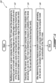
FIG. 5 is a flow diagram showing a method of constructing a computer model to be used in constructing a turbine exhaust case (TEC) mixer for an aircraft engine, according to the present technology; -
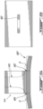
FIG. 6A is an elevation view of a T-joint being modified according to the present technology; -
FIG. 6B is a plan view of the T-joint ofFIG. 6A ; -
FIG. 7A is an elevation view of an L-joint being modified according to the present technology; and -
FIG. 7B is a plan view of the L-joint ofFIG. 7A . - It will be noted that throughout the appended drawings, like features are identified by like reference numerals.
-
FIG. 1 illustrates aturbofan aircraft engine 8 which includes anacelle 10, acore casing 13, a lowpressure spool assembly 12 which includes afan assembly 14, a lowpressure compressor assembly 16 coupled to a lowpressure turbine assembly 18, and a high pressure spool assembly seen generally at 20 which includes a highpressure compressor assembly 22 coupled to a highpressure turbine assembly 24. - The
core casing 13 surrounds the low and high pressure spool assemblies 12, 20 in order to define a main fluid path (not numbered) therethrough. In the main fluid path there is provided acombustion chamber 26 in which a combustion process produces combustion gases that power the high and low turbine pressure assemblies 24, 18. Thecore casing 13 extends from a front portion of theaircraft engine 8 toward a hub /inner shroud 28 disposed at a rear of theaircraft engine 8 downstream of the highpressure turbine assembly 24. - The
aircraft engine 8 further includes a turbine exhaust case (TEC)mixer 30 which is disposed downstream of the highpressure turbine assembly 24. The hub /inner shroud 28 may be circular in shape, for example, and may have an annular body. TheTEC mixer 30 surrounds the hub /inner shroud 28 to form an annularexhaust gas duct 32 disposed radially therebetween. Hot exhaust gases 13EX that are discharged from the pressure turbine assemblies 18, 24 exit the main fluid path of theaircraft engine 8 and pass through theexhaust gas duct 32. - Also, a bypass airstream 10BP driven by the
fan assembly 14 flows through anannular bypass duct 15 defined radially between thenacelle 10 and thecore casing 13. At least part of the bypass airstream 10BP exits theaircraft engine 8 by passing through, or along, the TECmixer 30. At least part of the bypass airstream 10BP and at least part of the hot exhaust gases 13EX mix at least after exiting theaircraft engine 8. - Referring to
FIG. 1 , the hub /inner shroud 28 and theTEC mixer 30 may define acentral axis 34 that is substantially collinear with a central rotation axis of theaircraft engine 8, or parallel or quasi parallel to the central rotation axis. For the purposes of this document, the terms "upstream" and "downstream" are used to refer to the direction of a fluid flow passing through the main fluid path of an aircraft engine. The terms "axial", "radial" and "circumferential" are used with respect to thecentral axis 34 of theaircraft engine 8. The terms "forward" and "rearward" are used with respect to the direction of flight. - The
TEC mixer 30 according to one embodiment such as the one shown inFIG. 1 includes anannular wall 31 around thecentral axis 34. Theannular wall 31 of theTEC mixer 30 defines theexhaust gas duct 32. In the present embodiment, theannular wall 31 is distinct from thecore casing 13, and from the shroud(s) and other elements of thecore casing 13. However, it is contemplated that theannular wall 31 could be part of thecore casing 13 and/or other element(s) of theaircraft engine 8 for example. - The
annular wall 31 is shaped for directing at least part of the bypass airstream 10BP that exits thebypass air duct 15. The shape of theannular wall 31 of theTEC mixer 30 may in at least some embodiments establish a vortex system downstream of theTEC mixer 30 to encourage mixing between the bypass airstream 10BP and the turbine exhaust gases 13EX at least downstream of theTEC mixer 30 during operation of theaircraft engine 8. - As schematically shown in
Fig. 1 , theTEC mixer 30 includes a plurality ofstruts 36 that are circumferentially distributed and spaced apart along an inner surface of theannular wall 31. Thestruts 36 have leading and trailing edges (36L, 36T respectively) and extend in a chord-wise direction along at least a part of an axial length of theannular wall 31, for example between an upstream end and a downstream end of theannular wall 31, or at other points. Thestruts 36 are distributed circumferentially around the hub /inner shroud 28, in this example, at equal circumferential distances, though the skilled reader will appreciate that thestruts 36 spacing could be different. Thestruts 36 extend generally radially. Any suitable arrangement forstruts 36 may be employed, however. - In the present embodiment, the
struts 36 extend in a span-wise direction across the annularexhaust gas duct 32 and connect theTEC mixer 30 to the inner shroud, and more particularly in this embodiment to the hub /inner shroud 28. More particularly, in the present embodiment, thestruts 36 extend from theannular wall 31 of theTEC mixer 30 to the hub /inner shroud 28. - In at least some embodiments, the
struts 36 may be shaped, positioned, oriented and sized so as to at least in part deswirl the exhaust gases 13EX that pass through theexhaust gas duct 32. In some embodiments, one or more of thestruts 36 may be structural in nature and need not provide a deswirling action. One or more of thestruts 36 may be at least in part disposed outside of theexhaust gas duct 32 and/or may connect to a different part of theaircraft engine 8 than the hub /inner shroud 28. - Now referring to
Fig. 2 , one of thestruts 36 of the present embodiment is shown in more detail. In the present embodiment, the rest of thestruts 36 are similar to thestrut 36 shown inFig. 2 . The rest of thestruts 36 are therefore not described in detail. It is contemplated that some of thestruts 36 could have a different shape than the rest of thestruts 36. - As shown in
Fig. 2 , thestrut 36 includes aleading surface 36L oriented forward, and a trailingsurface 36T oriented rearward. The expression "edge surface" is used for 36L and 36T, but they may also be referred to as leadingedge 36L and trailingedge 36T, or even leadingedge surface 36L and trailingedge surface 36T. Thestrut 36 may also include an shroud-strut interface 36IN, for connection to the hub /inner shroud 28, and an annular-wall-to-strut interface 36OUT for connection to theannular wall 31. The leadingsurface 36L may extend between a front portion of the shroud-strut interface 36IN and a front portion of the annular-wall-to-strut interface 36OUT and may face into the stream of exhaust gases 13EX. The trailingsurface 36T may extend between a rear portion of the shroud-strut interface 36IN and a rear portion of the annular-wall-to-strut interface 36OUT. - In the present embodiment, the shroud-strut interface 36IN is connected along its length to the hub /
inner shroud 28 by being welded to a corresponding portion of the hub /inner shroud 28. It is contemplated that a different connecting arrangement could be used to connect the shroud-strut interface 36IN, directly or indirectly, to the hub /inner shroud 28 or other part of theaircraft engine 8, for example, such as brazing, soldering, casting. The annular-wall-to-strut interface 36OUT is connected along its length to theannular wall 31. It is contemplated that any suitable connecting arrangement could be used to connect the annular-wall-to-strut interface 36OUT to theannular wall 31, such as those mentioned above for the shroud-strut interface 36IN. - As shown in
Fig. 2 , in the present embodiment, the leadingsurface 36L of thestrut 36 is defined by a cavity (not numbered), and the trailingsurface 36T is defined by a cavity (not numbered). In the present embodiment, as shown inFig. 2 , the cavity defining the leadingsurface 36L of thestrut 36 is an inward cavity extending in a rearward direction from a straightradial line 38F extending from a forward tip of the shroud-strut interface 361N to a forward tip of the annular-wall-to-strut interface 36OUT. - Also as in the present embodiment, as shown in
Fig. 2 , the cavity defining the trailingsurface 36T is an inward cavity extending in a forward direction from a straightradial line 38R extending from a rearward tip of the shroud-strut interface 361N to a rearward tip of the annular-wall-to-strut interface 36OUT. As shown, boundaries of each of the two cavities are spaced from the shroud-strut interface 361N and the annular-wall-to-strut interface 36OUT, and hence also from the axial ends of thestrut 36. It is contemplated that in some embodiments, at least one of the cavities could extend to one or both of the shroud-strut interface 36IN and the annular-wall-to-strut interface 36OUT. - Still referring to
Fig. 2 , in the present embodiment, each of the cavities includes a curved portion proximate to the shroud-strut interface 361N. Each of the cavities also includes a curved portion proximate to the annular-wall-to-strut interface 36OUT. As shown, a tangent to a part of each of the curved portions defines an angle θ1, θ2, θ3, θ4, respectively, with a tangent to a part of a respective one of the shroud-strut interface 36IN and the annular-wall-to-strut interface 36OUT. The spacing of the boundaries of the cavities from the inner and annular-wall-to-strut interfaces 36IN, 36OUT forms a steppedstructure 40 at each corner of thestrut 36. It is contemplated that one or more of thestruts 36 could have fewer than the four steppedstructures 40 and/or could have none of the steppedstructures 40. - The angles θ1, θ2, θ3, θ4 provide a taper that helps increase a flexibility of the
struts 36 at least at the extremities of the shroud-strut interface 36IN and the annular-wall-to-strut interface 36OUT. In at least some embodiments and/or applications, the increased flexibility helps reduce peak stresses along at least parts of the shroud-strut interfaces 36IN and the annular-wall-to-strut interfaces 36OUT of thestruts 36. In the present embodiment, the angles θ1, θ2, θ3, θ4 are different, but are all less than fifteen degrees. In some embodiments, the angles θ1, θ2, θ3, θ4 are different, but are all less than thirty degrees. Further in the present embodiment, the angles θ3, θ4 are each less than five degrees. In some embodiments, the angles θ1, θ2, θ3, θ4 are each less than thirty degrees. In an embodiment, the angles θ1, θ2, θ3, θ4 range from 0 to 15 degrees. In another embodiment, the angles θ1, θ2, θ3, θ4 range from 0 to 30 degrees. Such relatively small angles help reduce peak stresses along the respective one(s) of the shroud-strut interface 36IN and the annular-wall-to-strut interface 36OUT. It is contemplated that in some embodiments, one or both of the cavities could include only one of the respective curved portions. - Now referring to
Fig. 3 , the steppedstructure 40 at the rearward tip of the shroud-strut interface 36IN of thestrut 36 is shown. In the present embodiment, the steppedstructures 40 are similar to each other. As shown, in the present embodiment, afirst step 40A of each of the steppedstructures 40 is connected to a respective one of theannular wall 31 and the hub /inner shroud 28, and asecond step 40B of each of the steppedstructures 40 is disposed between thefirst step 40A and a generally middle portion 36MS (Fig. 2 ) or mid-span region of thestrut 36. In the embodiment shown, thefirst step 40A is wider than thesecond step 40B, and may be said to have a larger footprint defining the shroud-strut interface 36IN. In this description, the term "mid-span" is intended to refer to any portion of the span away from the ends of the strut, such as between about 30-70% of the span. - As shown in
Fig. 3 , the (radially inner)first step 40A is defined by planar surfaces and fillets between the planar surfaces and the hub/inner shroud 28 and/or asecond step 40B,, with the planar surfaces being angled relative to a plane tangent to a part of an outer surface of the hub /inner shroud 28 to which thefirst step 40A connects. In the case of the (outer)first steps 40A of thestrut 36 that connect to theannular wall 31, each of thosefirst steps 40A is similarly defined by planar surfaces and fillets, with the planar surfaces being angled relative to a plane tangent to a part of a surface of theannular wall 31 to thatfirst step 40A connects. - As shown in
Fig. 3 , each of the planar surfaces of the (inner)first step 40A defines anacute angle 42 with a plane tangent to a part of the outer surface of the hub /inner shroud 28 to which thefirst step 40A connects, and anobtuse angle 44 with a contiguous/adjacent planar surface of the correspondingsecond step 40B. Correspondingly, the (outer)first steps 40A of thestrut 36 define an acute angle with the outer surface of the hub /inner shroud 28 to which they connect and anobtuse angle 44 with a contiguous/adjacent surface of each correspondingsecond step 40B. - In the present embodiment, the
second step 40B is disposed radially closer to the middle portion 36MS of thestrut 36 than thefirst step 40A. Thesecond step 40B includes a planar surface 40PS disposed between the curved portion and thefirst step 40A. In the present embodiment, the planar surface 40PS defines the angle θ2 (Fig. 2 ) with a corresponding part of the shroud-strut interface 361N. Stated differently, a projection of the planar surface 40PS would intersect a projection of shroud-strut interface 36IN and these projections would define the angle θ2 therebetween. In one aspect, this feature provides a smooth transition between the planar surface 40PS and the contiguous corresponding curved portion of thestrut 36. - Still referring to
Fig. 3 , thesecond step 40B may further includeconvex portion 40X disposed between the planar surface 40PS and thefirst step 40A. In the present embodiment, theconvex portion 40X is arcuate, but it is contemplated that other shapes could also be used. Theconvex portion 40X provides a smooth transition between thefirst step 40A and thesecond step 40B. Similarly, the planar surface 40PS provides a smooth transition between theconvex portion 40X and the rest of the corresponding cavity in thestrut 36. It is contemplated that the surface 40PS could be non-planar. - Such smooth transitions may help reduce a peak stress in the
strut 36 in at least at one point when theTEC mixer 30 is in use, and hence may help improve an expected life of thestruts 36 in at least some applications of theTEC mixer 30. It is contemplated that one or more of the steppedstructures 40 could have a greater or a smaller number of the smooth transitions. It is also contemplated that the particular characteristics of the smooth transitions could be selected to suit each particular embodiment and application of theTEC mixer 30. - In the present embodiment, each of the stepped
structures 40 may help reduce peak stresses in thestrut 36 along the respective ones of the inner and annular-wall-to-strut interfaces 36IN, 36OUT. With regard to the steppedstructure 40 shown inFig. 3 for example, it has been found that the steppedstructures 40 may help reduce peak stresses in thestrut 36 at least in atransverse direction 46 out of plane with thestrut 36 and in alongitudinal direction 48 along the shroud-strut interface 361N. Therefore, the steppedstructure 40 shown inFig. 3 is a non-limiting embodiment of a means for reducing at least one stress in at least some of thestruts 36. In the present embodiment, the means is a means for reducing at least one stress in at least the strut having the means. - At least some embodiments of the technology described herein above may be said to provide a
TEC mixer 30 for anaircraft engine 8 configured for mixing concentric core and bypass gas flows via a lobed mixer (not separately numbered, shown schematically inFig. 1 ), theTEC mixer 30 comprisingstruts 36 extending in a span-wise direction from mixer lobes (not separately numbered, shown schematically inFig. 1 ) to aninner shroud 28 across the core gas flow, eachstrut 36 having leading and trailingedges strut 26 being axially narrower in the chord at a mid-span portion of thestrut 36 than at an interface of thestrut 36 and theinner shroud 28. - With the above embodiments and structures in mind, a
method 100 of constructing a computer model to be used in constructing aTEC mixer 30 for anaircraft engine 8 is described next. - Referring to
Fig. 4 , in some embodiments, themethod 100 may be executed at a server 80 that includes aprocessor 82 and anon-transient memory 84 communicatively coupled to theprocessor 82, thenon-transient memory 84 storing processor-executable instructions which, when executed by theprocessor 82 cause the server 80 to execute the functionality described in this document. - In some embodiments, the server 80 could be a single physical computer, such as a desktop or a laptop. In other embodiments, the server 80 could be a distributed server and/or a cloud-based server. In the present embodiment, the server 80 is a desktop computer connected to a monitor 86,
mouse 88, and keyboard 90. In the present embodiment, theprocessor 82 includes a central processing unit (CPU) and a graphics processor coupled to the CPU. It is contemplated that any server 80 may be used, so long as the steps of themethod 100 can be carried out thereon. - In some embodiments, the
method 100 may start by obtaining a given computer model (e.g. seeFig. 2 ) of a given TEC mixer. In some such cases, the given TEC mixer may have struts one or more of which may have the shape shown withreference lines Fig. 2 . - The
method 100 may include a step of executing at the server 80, based on the given computer model, a stress analysis of the struts of the given TEC mixer being in use in the given TEC mixer to determine a stress distribution in each of the struts. In some cases, the stress analysis may be based on finite element analysis (FEA) according to conventional FEA techniques. - In some embodiments, the stress analysis includes determining at least one of: a membrane stress, a secondary stress, and a peak stress, in each of the struts of the given TEC mixer. An example of a stress distribution 101S is schematically shown in
Fig. 2 and indicates peak stresses (shown in dashed lines) in a given one of the struts atlocations Fig. 2 . - The
method 100 may further include a step of identifying magnitudes of at least one type of stress in the stress distribution of each of the struts. In some cases, this step may include determining that a magnitude of the at least one type of stress in at least one of the struts is higher than a magnitude of the at least one type of stress in at least another one of the struts. As such, an imbalance in in-use stress distribution within the struts may be determined, and therefore one or more struts having at least one "over-stressed" point (relative to other points in other ones of the struts) may be identified. - According to the present technology, material is removed from the identified "over-stressed" point(s), thereby making the corresponding part(s) of the strut(s) containing the point(s) relatively more flexible. It has been found that the resulting added flexibility at or proximate to the "over-stressed" point(s) helps absorb and more evenly redistribute one or more stresses from the "over-stressed" point(s) to other location(s) in the structure which may be "under-stressed". In at least some cases, the identified stress distribution imbalance(s) is/are decreased and an expected life of the TEC mixer is lengthened. In at least some cases, the strategic removal of material from, or proximate to, the "over-stressed" point(s) allows to better utilize structural parts of the TEC mixer which had been under-utilized before application of the
method 100, and in at least some cases allows to avoid adding material to the TEC mixer and thus helps reduce a weight of the TEC mixer. - To this end, in some embodiments, the
method 100 may includestep 102, which may include modifying, at the server 80, one or more of the identified struts in the given computer model of the TEC mixer by removing a part of at least one of a leading surface and a trailing surface the strut(s) determined to be "relatively over stressed" according to the results of the stress analysis described above. In some embodiments, this removal of material includes creating one or more cavities in the leading and/or trailing surfaces of the "relatively over stressed" strut(s). In some embodiments, the boundaries of the cavity(ies) are defined so as to be spaced from at least one of an annular-wall-to-strut interface and an shroud-strut interface of the strut(s). It has been found that, in at least some cases, such spacing of the cavity boundaries helps improve stress redistribution. - As an example, as shown in
Fig. 3 , a part of each of the leading surface and a trailing surface of each identified "relatively over stressed" strut of the TEC mixer may be removed in the given computer model proximate or at to the identified "relatively over-stressed" location(s) 51-54. In some embodiments, the resulting cavities may be iteratively re-shaped as described below, to achieve a desired in-use stress distribution throughout the struts of the TEC mixer. That is, for example themethod 100 may includestep 104, which may include executing, at the server 80, based on the given computer model modified as described above, another stress analysis of the modified struts being in use to determine a measure of suitability of the struts for the use. - The measure of suitability may be any suitable measure of suitability according to known engineering and stress analysis methods suitable for each particular embodiment of the TEC mixer. In some embodiments, the subsequent stress analysis may be similar to the earlier stress analysis described above. In some embodiments, the measure of suitability may be an expected life of the modified TEC mixer based on the new shape(s) of the modified strut(s). That is, the analysis may include determining an expected life of the TEC mixer based on a subsequently determined resulting stress distribution in the struts of the TEC mixer.
- The
method 100 may then proceed to a step of determining whether the measure of suitability determined atstep 104 exceeds a predetermined threshold. In some embodiments, the predetermined threshold may be for example a predetermined minimum required expected life of the modified strut(s) and/or the modified TEC mixer. It is contemplated that other metrics could likewise be used. In cases where it is determined that the measure of suitability does exceed the desired / predetermined threshold, themethod 100 may proceed to astep 106 of generating, at the server 80, an indication that the modified computer model is the computer model to be used for constructing the TEC mixer. - On the other hand, in cases where it is determined that the measure of suitability from
step 104 is below the predetermined threshold, themethod 100 may proceed to one or more steps of iteratively modifying the shape(s) of the cavity(ies) and/or adding or removing cavity(ies) according to the principles described above in one or more of the strut(s), and thereafter executing corresponding subsequent iteration(s) of stress/suitability analyses as described above to determine when the chosen measure(s) of suitability of the struts finally exceed(s) the desired / predetermined threshold. Once desired / predetermined threshold is met, themethod 100 may proceed to thestep 106 of generating, at the server 80, the indication that the subsequently modified computer model is the computer model that is to be used to construct theTEC mixer 30. - Also, in some embodiments, even after it is determined that the measure(s) of suitability exceed(s) the desired / predetermined threshold(s), the
method 100 may include further iterative cavity modification, addition, or removal steps similar to those described above to further improve stress distribution in the gien TEC mixer, before generating an indication that the given computer model is to be used to construct the TEC mixer. - For example, in some cases, the
method 100 may include, after determining that the measure(s) exceed(s) the desired / predetermined threshold, modifying a shape of one or more cavities to reduce a height (H) (Figs. 2 and3 ) of a part of the corresponding strut(s) between the cavity(ies) and the at least one of the shroud-strut interface and the annular-wall-to-strut interface of the corresponding strut(s), and executing subsequent iteration(s) of stress/suitability analyses to re-check whether the resulting measure(s) of suitability of the strut(s) have been further improved, before generating an indication that the given computer model is to be used to construct the TEC mixer. - Once a given version of the given computer model is "finalized", one or more TEC mixers may be constructed based thereon using any suitable known manufacturing method. It is contemplated that in each given TEC mixer, the particular sizes, orientations and positions of the struts thereof may be selected using known engineering principles to suit each particular embodiment and application of the given TEC mixer.
- Reference is now made to
Figs. 6A, 6B ,7A, and 7B , which show examples of a T-joint 600 and an L-joint 700 of the type used in constructing larger structures. As shown with dashed cut-out lines, the T-joint 600 and the L-joint 700 are being modified according to the present technology. More particularly, once modified or constructed, the T-joint 600 includes acavities 601 made therein according to the principles discussed above. Similarly, once modified or constructed, the L-joint 700 includes asingle cavity 701 made therein according to the principles discussed above. - These modifications have been found at least in some applications of the
joints joints locations cavities - The above description is meant to be exemplary only, and one skilled in the art will recognize that changes may be made to the embodiments described without departing from the scope of the described subject matter. The scope of protection however is conferred in the appended claims.
Claims (15)
- A turbine exhaust case (TEC) mixer (30) for an aircraft engine (8) having an inner shroud (28), a nacelle (10), a fan assembly (14), a compressor assembly (16) and a turbine assembly (24), the TEC mixer (30) comprising struts (36) being adapted to connect to an inner shroud (28) at a shroud-strut interface (36IN), a plurality of the struts (36) being narrower in a middle portion (36MS) thereof than at the shroud-strut interface (36IN), wherein each strut (36) of the plurality of struts (36) has a leading surface (36L) and a trailing surface (36T), at least one of the leading surface (36L) and the trailing surface (36T) is defined by a cavity, and boundaries of the cavity are spaced from axial ends of the strut (36).
- The TEC mixer of claim 1, further comprising an annular wall (31) adapted to be disposed about a central axis (34) of the aircraft engine (8) downstream of the turbine assembly (24), wherein the plurality of struts (36) extend from the annular wall (31).
- The TEC mixer of claim 1 or 2, wherein the cavity is a first cavity that defines the leading surface (36L) of the strut (36), the trailing surface (36T) is defined by a second cavity, and boundaries of the second cavity are spaced from the axial ends of the strut (36).
- The TEC mixer of any preceding claim, wherein the cavity is defined in part by a curved portion proximate to the shroud-strut interface (36IN) of the strut (36), a tangent to a part of the curved portion defines an angle with a tangent to a part of the shroud-strut interface (36IN), and the angle is less than thirty degrees.
- The TEC mixer of any preceding claim, wherein the strut (36) includes a stepped structure (40) at the shroud-strut interface (36IN), the stepped structure (40) including a first step (40A) adapted to be connected to the inner shroud (28) of the aircraft engine (8) and a second step (40B) disposed closer to the middle portion (36MS) of the strut (36) than the first step (40A).
- The TEC mixer of claim 5, wherein the first step (40A) is defined by planar surfaces and fillets.
- The TEC mixer of claim 5 or 6, wherein the first step (40A) includes a planar surface that defines an acute angle (42) with a plane tangent to a part of the shroud-strut interface (361N).
- The TEC mixer of claim 7, wherein the planar surface defines an obtuse angle (44) with an adjacent planar surface of the second step (40B).
- The TEC mixer of claim 6, 7 or 8, wherein the second step (40B) includes a planar surface (40PS) disposed between the first step (40A) and the middle portion (36MS), and the planar surface (40PS) defines an angle (θ2)with the tangent to the part of the shroud-strut interface (36IN), the angle (θ2) being less than thirty degrees.
- The TEC mixer of claim 9, wherein the second step (40B) further includes a convex portion (40X) disposed between the planar surface (40PS) of the second step (40B) and the first step (40A).
- The TEC mixer of any preceding claim, wherein the (TEC) mixer (30) is configured for mixing concentric core and bypass gas flows via a lobed mixer, the struts (36) configured to extend in a span-wise direction from mixer lobes to the inner shroud (28) across a core gas flow.
- A turbine exhaust case (TEC) mixer (30) for an aircraft engine (8) having an inner shroud (28), a nacelle (10), a fan assembly (14), a compressor assembly (16) and a turbine assembly (24), the TEC mixer (30) comprising struts (36) being adapted to connect to an inner shroud (28) at a shroud-strut interface (36IN), at least one of the struts (36) including a stepped configuration (40) for reducing at least one stress in the at least one of the struts (36), wherein the stepped configuration (40) includes a first step (40A) defining the shroud-strut interface (36IN) and a second step (40B) extending from the first step (40A) toward a middle portion (36MS) of the at least one of the struts (36), and the first step (40A) has a larger footprint than the second step (40B).
- The TEC mixer of claim 12, wherein the TEC mixer (30) includes an annular wall (31) adapted to be disposed about a central axis (34) of the aircraft engine (8) downstream of the turbine assembly (24), and the stepped configuration (40) includes a first step (40A) defining an annular-wall-to-strut interface (36OUT) and a second step (40B) extending from the first step (40A) defining the annular-wall-to-strut interface (36OUT) toward the middle portion (36MS) of the at least one of the struts (36), and the first step (40A) defining the annular-wall-to-strut interface (36OUT) has a larger footprint than the second step (40A) associated with the annular-wall-to-strut interface (36OUT).
- The TEC mixer of claim 12 or 13, wherein the at least one of the struts (36) is axially narrower in a middle portion (36MS) thereof than at the shroud-strut interface (36IN).
- The TEC mixer of claim 14, wherein the at least one of the struts (36) has a leading surface (36L) and a trailing surface (36T), at least one of the leading surface (36L) and the trailing surface (36T) is defined by a cavity, and boundaries of the cavity are spaced from axial ends of the strut (36).
Applications Claiming Priority (2)
| Application Number | Priority Date | Filing Date | Title |
|---|---|---|---|
| US201962830752P | 2019-04-08 | 2019-04-08 | |
| US16/382,930 US12601283B2 (en) | 2019-04-08 | 2019-04-12 | Turbine exhaust case mixer |
Publications (2)
| Publication Number | Publication Date |
|---|---|
| EP3722583A1 EP3722583A1 (en) | 2020-10-14 |
| EP3722583B1 true EP3722583B1 (en) | 2023-05-31 |
Family
ID=70227952
Family Applications (1)
| Application Number | Title | Priority Date | Filing Date |
|---|---|---|---|
| EP20168833.0A Active EP3722583B1 (en) | 2019-04-08 | 2020-04-08 | Turbine exhaust case mixer |
Country Status (3)
| Country | Link |
|---|---|
| US (1) | US12601283B2 (en) |
| EP (1) | EP3722583B1 (en) |
| CA (1) | CA3077765A1 (en) |
Families Citing this family (2)
| Publication number | Priority date | Publication date | Assignee | Title |
|---|---|---|---|---|
| US12162618B2 (en) * | 2021-10-11 | 2024-12-10 | Boom Technology, Inc. | Dissimilarly shaped aircraft nozzles with tandem mixing devices, and associated systems and methods |
| DE102022101661A1 (en) * | 2022-01-25 | 2023-07-27 | MTU Aero Engines AG | Connection structure for load transfer |
Family Cites Families (22)
| Publication number | Priority date | Publication date | Assignee | Title |
|---|---|---|---|---|
| US4117671A (en) | 1976-12-30 | 1978-10-03 | The Boeing Company | Noise suppressing exhaust mixer assembly for ducted-fan, turbojet engine |
| US4226085A (en) | 1978-02-13 | 1980-10-07 | United Technologies Corporation | Unitary plug mixer and support therefor |
| US4817378A (en) | 1987-02-13 | 1989-04-04 | General Electric Company | Gas turbine engine with augmentor and variable area bypass injector |
| US5272869A (en) * | 1992-12-10 | 1993-12-28 | General Electric Company | Turbine frame |
| US5595040A (en) | 1994-07-20 | 1997-01-21 | National Science Council | Beam-to-column connection |
| US6312219B1 (en) | 1999-11-05 | 2001-11-06 | General Electric Company | Narrow waist vane |
| US6554569B2 (en) | 2001-08-17 | 2003-04-29 | General Electric Company | Compressor outlet guide vane and diffuser assembly |
| US20140260283A1 (en) * | 2013-03-12 | 2014-09-18 | Pratt & Whitney Canada Corp. | Gas turbine engine exhaust mixer with aerodynamic struts |
| US8206095B2 (en) * | 2008-11-19 | 2012-06-26 | Alstom Technology Ltd | Compound variable elliptical airfoil fillet |
| GB0905729D0 (en) * | 2009-04-03 | 2009-05-20 | Rolls Royce Plc | Stator vane assembly |
| US8734085B2 (en) | 2009-08-17 | 2014-05-27 | Pratt & Whitney Canada Corp. | Turbine section architecture for gas turbine engine |
| EP2441918A1 (en) * | 2010-10-18 | 2012-04-18 | Siemens Aktiengesellschaft | Gas turbine annular diffuser |
| US8944753B2 (en) | 2011-11-09 | 2015-02-03 | Pratt & Whitney Canada Corp. | Strut mounting arrangement for gas turbine exhaust case |
| BR122015003108B1 (en) | 2012-06-15 | 2023-05-09 | United Technologies Corporation | GAS TURBINE ENGINE |
| US9534498B2 (en) * | 2012-12-14 | 2017-01-03 | United Technologies Corporation | Overmolded vane platform |
| US11085333B2 (en) | 2013-07-09 | 2021-08-10 | Pratt & Whiiney Canada Corp. | Exhaust mixer with offset lobes |
| US20150075169A1 (en) * | 2013-09-19 | 2015-03-19 | Pratt & Whitney Canada Corp. | Integrated turbine exhaust struts and mixer of turbofan engine |
| JP6546481B2 (en) | 2015-08-31 | 2019-07-17 | 川崎重工業株式会社 | Exhaust diffuser |
| EP3260666A1 (en) * | 2016-06-23 | 2017-12-27 | General Electric Company | Exhaust frame of a gas turbine engine |
| US10119449B2 (en) * | 2016-08-02 | 2018-11-06 | The Boeing Company | Systems and methods for restraining exhaust gas ducts |
| US11118481B2 (en) | 2017-02-06 | 2021-09-14 | Raytheon Technologies Corporation | Ceramic matrix composite turbine exhaust assembly for a gas turbine engine |
| DE102017218886A1 (en) * | 2017-10-23 | 2019-04-25 | MTU Aero Engines AG | Shovel and rotor for a turbomachine and turbomachine |
-
2019
- 2019-04-12 US US16/382,930 patent/US12601283B2/en active Active
-
2020
- 2020-04-01 CA CA3077765A patent/CA3077765A1/en active Pending
- 2020-04-08 EP EP20168833.0A patent/EP3722583B1/en active Active
Also Published As
| Publication number | Publication date |
|---|---|
| US12601283B2 (en) | 2026-04-14 |
| CA3077765A1 (en) | 2020-10-08 |
| EP3722583A1 (en) | 2020-10-14 |
| US20200318495A1 (en) | 2020-10-08 |
Similar Documents
| Publication | Publication Date | Title |
|---|---|---|
| CN106050333B (en) | Shroud assembly and shroud for a gas turbine engine | |
| CN113167120B (en) | Profiled structure for an aircraft or turbine | |
| CN102562178B (en) | Turbine nozzle for air cycle machine | |
| US9874101B2 (en) | Platform with curved edges | |
| CA2893243C (en) | Compressor rotor airfoil with leading edge dihedral distribution having multiple inflection points | |
| EP3118412B1 (en) | Method for generating an airfoil including an aerodynamically-shaped fillet and airfoils including the aerodynamically-shaped fillet | |
| CA1283366C (en) | Reduced loss swept supersonic fan blade | |
| EP3379031B1 (en) | Fan rotor with flow induced resonance control | |
| EP3460186B1 (en) | Compressor rotor, corresponding gas turbine engine and method of reducing flow pattern disparities | |
| EP3208467A1 (en) | Compressor rotor for supersonic flutter and/or resonant stress mitigation | |
| CN111315964B (en) | Dimple for outer housing shroud | |
| US10443390B2 (en) | Rotary airfoil | |
| EP3722583B1 (en) | Turbine exhaust case mixer | |
| CN112119204A (en) | Turbomachine stator element | |
| EP3379029A1 (en) | Fan rotor with flow induced resonance control | |
| US10480535B2 (en) | Fan rotor with flow induced resonance control | |
| JP5264058B2 (en) | Fixed turbine airfoil | |
| EP3372786B1 (en) | High-pressure compressor rotor blade with leading edge having indent segment | |
| US10364773B2 (en) | Gas turbine engine | |
| US20180016915A1 (en) | Turbomachine component having a platform cavity with a stress reduction feature | |
| Ashihara et al. | Optimization of microturbine aerodynamics using CFD, inverse design and FEM structural analysis: 1st report—compressor design | |
| WO2016068862A1 (en) | Gas turbine engine | |
| US9784286B2 (en) | Flutter-resistant turbomachinery blades | |
| CN104411982B (en) | Turbine guide vanes with improved blade profile |
Legal Events
| Date | Code | Title | Description |
|---|---|---|---|
| PUAI | Public reference made under article 153(3) epc to a published international application that has entered the european phase |
Free format text: ORIGINAL CODE: 0009012 |
|
| STAA | Information on the status of an ep patent application or granted ep patent |
Free format text: STATUS: THE APPLICATION HAS BEEN PUBLISHED |
|
| AK | Designated contracting states |
Kind code of ref document: A1 Designated state(s): AL AT BE BG CH CY CZ DE DK EE ES FI FR GB GR HR HU IE IS IT LI LT LU LV MC MK MT NL NO PL PT RO RS SE SI SK SM TR |
|
| AX | Request for extension of the european patent |
Extension state: BA ME |
|
| STAA | Information on the status of an ep patent application or granted ep patent |
Free format text: STATUS: REQUEST FOR EXAMINATION WAS MADE |
|
| 17P | Request for examination filed |
Effective date: 20210414 |
|
| RBV | Designated contracting states (corrected) |
Designated state(s): AL AT BE BG CH CY CZ DE DK EE ES FI FR GB GR HR HU IE IS IT LI LT LU LV MC MK MT NL NO PL PT RO RS SE SI SK SM TR |
|
| GRAP | Despatch of communication of intention to grant a patent |
Free format text: ORIGINAL CODE: EPIDOSNIGR1 |
|
| STAA | Information on the status of an ep patent application or granted ep patent |
Free format text: STATUS: GRANT OF PATENT IS INTENDED |
|
| INTG | Intention to grant announced |
Effective date: 20221209 |
|
| GRAS | Grant fee paid |
Free format text: ORIGINAL CODE: EPIDOSNIGR3 |
|
| GRAA | (expected) grant |
Free format text: ORIGINAL CODE: 0009210 |
|
| STAA | Information on the status of an ep patent application or granted ep patent |
Free format text: STATUS: THE PATENT HAS BEEN GRANTED |
|
| AK | Designated contracting states |
Kind code of ref document: B1 Designated state(s): AL AT BE BG CH CY CZ DE DK EE ES FI FR GB GR HR HU IE IS IT LI LT LU LV MC MK MT NL NO PL PT RO RS SE SI SK SM TR |
|
| REG | Reference to a national code |
Ref country code: GB Ref legal event code: FG4D Ref country code: CH Ref legal event code: EP |
|
| REG | Reference to a national code |
Ref country code: AT Ref legal event code: REF Ref document number: 1571060 Country of ref document: AT Kind code of ref document: T Effective date: 20230615 Ref country code: DE Ref legal event code: R096 Ref document number: 602020011230 Country of ref document: DE |
|
| REG | Reference to a national code |
Ref country code: IE Ref legal event code: FG4D |
|
| P01 | Opt-out of the competence of the unified patent court (upc) registered |
Effective date: 20230530 |
|
| REG | Reference to a national code |
Ref country code: LT Ref legal event code: MG9D |
|
| REG | Reference to a national code |
Ref country code: NL Ref legal event code: MP Effective date: 20230531 |
|
| REG | Reference to a national code |
Ref country code: AT Ref legal event code: MK05 Ref document number: 1571060 Country of ref document: AT Kind code of ref document: T Effective date: 20230531 |
|
| PG25 | Lapsed in a contracting state [announced via postgrant information from national office to epo] |
Ref country code: SE Free format text: LAPSE BECAUSE OF FAILURE TO SUBMIT A TRANSLATION OF THE DESCRIPTION OR TO PAY THE FEE WITHIN THE PRESCRIBED TIME-LIMIT Effective date: 20230531 Ref country code: NO Free format text: LAPSE BECAUSE OF FAILURE TO SUBMIT A TRANSLATION OF THE DESCRIPTION OR TO PAY THE FEE WITHIN THE PRESCRIBED TIME-LIMIT Effective date: 20230831 Ref country code: ES Free format text: LAPSE BECAUSE OF FAILURE TO SUBMIT A TRANSLATION OF THE DESCRIPTION OR TO PAY THE FEE WITHIN THE PRESCRIBED TIME-LIMIT Effective date: 20230531 Ref country code: AT Free format text: LAPSE BECAUSE OF FAILURE TO SUBMIT A TRANSLATION OF THE DESCRIPTION OR TO PAY THE FEE WITHIN THE PRESCRIBED TIME-LIMIT Effective date: 20230531 |
|
| PG25 | Lapsed in a contracting state [announced via postgrant information from national office to epo] |
Ref country code: RS Free format text: LAPSE BECAUSE OF FAILURE TO SUBMIT A TRANSLATION OF THE DESCRIPTION OR TO PAY THE FEE WITHIN THE PRESCRIBED TIME-LIMIT Effective date: 20230531 Ref country code: PL Free format text: LAPSE BECAUSE OF FAILURE TO SUBMIT A TRANSLATION OF THE DESCRIPTION OR TO PAY THE FEE WITHIN THE PRESCRIBED TIME-LIMIT Effective date: 20230531 Ref country code: NL Free format text: LAPSE BECAUSE OF FAILURE TO SUBMIT A TRANSLATION OF THE DESCRIPTION OR TO PAY THE FEE WITHIN THE PRESCRIBED TIME-LIMIT Effective date: 20230531 Ref country code: LV Free format text: LAPSE BECAUSE OF FAILURE TO SUBMIT A TRANSLATION OF THE DESCRIPTION OR TO PAY THE FEE WITHIN THE PRESCRIBED TIME-LIMIT Effective date: 20230531 Ref country code: LT Free format text: LAPSE BECAUSE OF FAILURE TO SUBMIT A TRANSLATION OF THE DESCRIPTION OR TO PAY THE FEE WITHIN THE PRESCRIBED TIME-LIMIT Effective date: 20230531 Ref country code: IS Free format text: LAPSE BECAUSE OF FAILURE TO SUBMIT A TRANSLATION OF THE DESCRIPTION OR TO PAY THE FEE WITHIN THE PRESCRIBED TIME-LIMIT Effective date: 20230930 Ref country code: HR Free format text: LAPSE BECAUSE OF FAILURE TO SUBMIT A TRANSLATION OF THE DESCRIPTION OR TO PAY THE FEE WITHIN THE PRESCRIBED TIME-LIMIT Effective date: 20230531 Ref country code: GR Free format text: LAPSE BECAUSE OF FAILURE TO SUBMIT A TRANSLATION OF THE DESCRIPTION OR TO PAY THE FEE WITHIN THE PRESCRIBED TIME-LIMIT Effective date: 20230901 |
|
| PG25 | Lapsed in a contracting state [announced via postgrant information from national office to epo] |
Ref country code: FI Free format text: LAPSE BECAUSE OF FAILURE TO SUBMIT A TRANSLATION OF THE DESCRIPTION OR TO PAY THE FEE WITHIN THE PRESCRIBED TIME-LIMIT Effective date: 20230531 |
|
| PG25 | Lapsed in a contracting state [announced via postgrant information from national office to epo] |
Ref country code: SK Free format text: LAPSE BECAUSE OF FAILURE TO SUBMIT A TRANSLATION OF THE DESCRIPTION OR TO PAY THE FEE WITHIN THE PRESCRIBED TIME-LIMIT Effective date: 20230531 |
|
| PG25 | Lapsed in a contracting state [announced via postgrant information from national office to epo] |
Ref country code: SM Free format text: LAPSE BECAUSE OF FAILURE TO SUBMIT A TRANSLATION OF THE DESCRIPTION OR TO PAY THE FEE WITHIN THE PRESCRIBED TIME-LIMIT Effective date: 20230531 Ref country code: SK Free format text: LAPSE BECAUSE OF FAILURE TO SUBMIT A TRANSLATION OF THE DESCRIPTION OR TO PAY THE FEE WITHIN THE PRESCRIBED TIME-LIMIT Effective date: 20230531 Ref country code: RO Free format text: LAPSE BECAUSE OF FAILURE TO SUBMIT A TRANSLATION OF THE DESCRIPTION OR TO PAY THE FEE WITHIN THE PRESCRIBED TIME-LIMIT Effective date: 20230531 Ref country code: PT Free format text: LAPSE BECAUSE OF FAILURE TO SUBMIT A TRANSLATION OF THE DESCRIPTION OR TO PAY THE FEE WITHIN THE PRESCRIBED TIME-LIMIT Effective date: 20231002 Ref country code: EE Free format text: LAPSE BECAUSE OF FAILURE TO SUBMIT A TRANSLATION OF THE DESCRIPTION OR TO PAY THE FEE WITHIN THE PRESCRIBED TIME-LIMIT Effective date: 20230531 Ref country code: DK Free format text: LAPSE BECAUSE OF FAILURE TO SUBMIT A TRANSLATION OF THE DESCRIPTION OR TO PAY THE FEE WITHIN THE PRESCRIBED TIME-LIMIT Effective date: 20230531 Ref country code: CZ Free format text: LAPSE BECAUSE OF FAILURE TO SUBMIT A TRANSLATION OF THE DESCRIPTION OR TO PAY THE FEE WITHIN THE PRESCRIBED TIME-LIMIT Effective date: 20230531 |
|
| REG | Reference to a national code |
Ref country code: DE Ref legal event code: R097 Ref document number: 602020011230 Country of ref document: DE |
|
| PLBE | No opposition filed within time limit |
Free format text: ORIGINAL CODE: 0009261 |
|
| STAA | Information on the status of an ep patent application or granted ep patent |
Free format text: STATUS: NO OPPOSITION FILED WITHIN TIME LIMIT |
|
| PG25 | Lapsed in a contracting state [announced via postgrant information from national office to epo] |
Ref country code: SI Free format text: LAPSE BECAUSE OF FAILURE TO SUBMIT A TRANSLATION OF THE DESCRIPTION OR TO PAY THE FEE WITHIN THE PRESCRIBED TIME-LIMIT Effective date: 20230531 |
|
| 26N | No opposition filed |
Effective date: 20240301 |
|
| PG25 | Lapsed in a contracting state [announced via postgrant information from national office to epo] |
Ref country code: SI Free format text: LAPSE BECAUSE OF FAILURE TO SUBMIT A TRANSLATION OF THE DESCRIPTION OR TO PAY THE FEE WITHIN THE PRESCRIBED TIME-LIMIT Effective date: 20230531 Ref country code: IT Free format text: LAPSE BECAUSE OF FAILURE TO SUBMIT A TRANSLATION OF THE DESCRIPTION OR TO PAY THE FEE WITHIN THE PRESCRIBED TIME-LIMIT Effective date: 20230531 |
|
| PG25 | Lapsed in a contracting state [announced via postgrant information from national office to epo] |
Ref country code: BG Free format text: LAPSE BECAUSE OF FAILURE TO SUBMIT A TRANSLATION OF THE DESCRIPTION OR TO PAY THE FEE WITHIN THE PRESCRIBED TIME-LIMIT Effective date: 20230531 |
|
| PG25 | Lapsed in a contracting state [announced via postgrant information from national office to epo] |
Ref country code: MC Free format text: LAPSE BECAUSE OF FAILURE TO SUBMIT A TRANSLATION OF THE DESCRIPTION OR TO PAY THE FEE WITHIN THE PRESCRIBED TIME-LIMIT Effective date: 20230531 |
|
| PG25 | Lapsed in a contracting state [announced via postgrant information from national office to epo] |
Ref country code: MC Free format text: LAPSE BECAUSE OF FAILURE TO SUBMIT A TRANSLATION OF THE DESCRIPTION OR TO PAY THE FEE WITHIN THE PRESCRIBED TIME-LIMIT Effective date: 20230531 Ref country code: BG Free format text: LAPSE BECAUSE OF FAILURE TO SUBMIT A TRANSLATION OF THE DESCRIPTION OR TO PAY THE FEE WITHIN THE PRESCRIBED TIME-LIMIT Effective date: 20230531 |
|
| REG | Reference to a national code |
Ref country code: CH Ref legal event code: PL |
|
| PG25 | Lapsed in a contracting state [announced via postgrant information from national office to epo] |
Ref country code: LU Free format text: LAPSE BECAUSE OF NON-PAYMENT OF DUE FEES Effective date: 20240408 |
|
| REG | Reference to a national code |
Ref country code: BE Ref legal event code: MM Effective date: 20240430 |
|
| PG25 | Lapsed in a contracting state [announced via postgrant information from national office to epo] |
Ref country code: LU Free format text: LAPSE BECAUSE OF NON-PAYMENT OF DUE FEES Effective date: 20240408 |
|
| PG25 | Lapsed in a contracting state [announced via postgrant information from national office to epo] |
Ref country code: BE Free format text: LAPSE BECAUSE OF NON-PAYMENT OF DUE FEES Effective date: 20240430 |
|
| PG25 | Lapsed in a contracting state [announced via postgrant information from national office to epo] |
Ref country code: BE Free format text: LAPSE BECAUSE OF NON-PAYMENT OF DUE FEES Effective date: 20240430 Ref country code: CH Free format text: LAPSE BECAUSE OF NON-PAYMENT OF DUE FEES Effective date: 20240430 |
|
| PG25 | Lapsed in a contracting state [announced via postgrant information from national office to epo] |
Ref country code: IE Free format text: LAPSE BECAUSE OF NON-PAYMENT OF DUE FEES Effective date: 20240408 |
|
| PGFP | Annual fee paid to national office [announced via postgrant information from national office to epo] |
Ref country code: DE Payment date: 20250319 Year of fee payment: 6 |
|
| PG25 | Lapsed in a contracting state [announced via postgrant information from national office to epo] |
Ref country code: CY Free format text: LAPSE BECAUSE OF FAILURE TO SUBMIT A TRANSLATION OF THE DESCRIPTION OR TO PAY THE FEE WITHIN THE PRESCRIBED TIME-LIMIT; INVALID AB INITIO Effective date: 20200408 |
|
| PG25 | Lapsed in a contracting state [announced via postgrant information from national office to epo] |
Ref country code: HU Free format text: LAPSE BECAUSE OF FAILURE TO SUBMIT A TRANSLATION OF THE DESCRIPTION OR TO PAY THE FEE WITHIN THE PRESCRIBED TIME-LIMIT; INVALID AB INITIO Effective date: 20200408 |
|
| PGFP | Annual fee paid to national office [announced via postgrant information from national office to epo] |
Ref country code: GB Payment date: 20260319 Year of fee payment: 7 |
|
| PGFP | Annual fee paid to national office [announced via postgrant information from national office to epo] |
Ref country code: FR Payment date: 20260320 Year of fee payment: 7 |