EP3722565B1 - After-fan system for a gas turbine engine - Google Patents
After-fan system for a gas turbine engine Download PDFInfo
- Publication number
- EP3722565B1 EP3722565B1 EP20168376.0A EP20168376A EP3722565B1 EP 3722565 B1 EP3722565 B1 EP 3722565B1 EP 20168376 A EP20168376 A EP 20168376A EP 3722565 B1 EP3722565 B1 EP 3722565B1
- Authority
- EP
- European Patent Office
- Prior art keywords
- fan
- guide vane
- exit guide
- turbine
- vane array
- Prior art date
- Legal status (The legal status is an assumption and is not a legal conclusion. Google has not performed a legal analysis and makes no representation as to the accuracy of the status listed.)
- Active
Links
Images




Classifications
-
- F—MECHANICAL ENGINEERING; LIGHTING; HEATING; WEAPONS; BLASTING
- F02—COMBUSTION ENGINES; HOT-GAS OR COMBUSTION-PRODUCT ENGINE PLANTS
- F02K—JET-PROPULSION PLANTS
- F02K3/00—Plants including a gas turbine driving a compressor or a ducted fan
- F02K3/02—Plants including a gas turbine driving a compressor or a ducted fan in which part of the working fluid by-passes the turbine and combustion chamber
- F02K3/04—Plants including a gas turbine driving a compressor or a ducted fan in which part of the working fluid by-passes the turbine and combustion chamber the plant including ducted fans, i.e. fans with high volume, low pressure outputs, for augmenting the jet thrust, e.g. of double-flow type
- F02K3/06—Plants including a gas turbine driving a compressor or a ducted fan in which part of the working fluid by-passes the turbine and combustion chamber the plant including ducted fans, i.e. fans with high volume, low pressure outputs, for augmenting the jet thrust, e.g. of double-flow type with front fan
-
- F—MECHANICAL ENGINEERING; LIGHTING; HEATING; WEAPONS; BLASTING
- F02—COMBUSTION ENGINES; HOT-GAS OR COMBUSTION-PRODUCT ENGINE PLANTS
- F02K—JET-PROPULSION PLANTS
- F02K3/00—Plants including a gas turbine driving a compressor or a ducted fan
- F02K3/02—Plants including a gas turbine driving a compressor or a ducted fan in which part of the working fluid by-passes the turbine and combustion chamber
- F02K3/04—Plants including a gas turbine driving a compressor or a ducted fan in which part of the working fluid by-passes the turbine and combustion chamber the plant including ducted fans, i.e. fans with high volume, low pressure outputs, for augmenting the jet thrust, e.g. of double-flow type
-
- F—MECHANICAL ENGINEERING; LIGHTING; HEATING; WEAPONS; BLASTING
- F02—COMBUSTION ENGINES; HOT-GAS OR COMBUSTION-PRODUCT ENGINE PLANTS
- F02C—GAS-TURBINE PLANTS; AIR INTAKES FOR JET-PROPULSION PLANTS; CONTROLLING FUEL SUPPLY IN AIR-BREATHING JET-PROPULSION PLANTS
- F02C9/00—Controlling gas-turbine plants; Controlling fuel supply in air- breathing jet-propulsion plants
- F02C9/16—Control of working fluid flow
- F02C9/20—Control of working fluid flow by throttling; by adjusting vanes
-
- F—MECHANICAL ENGINEERING; LIGHTING; HEATING; WEAPONS; BLASTING
- F04—POSITIVE - DISPLACEMENT MACHINES FOR LIQUIDS; PUMPS FOR LIQUIDS OR ELASTIC FLUIDS
- F04D—NON-POSITIVE-DISPLACEMENT PUMPS
- F04D29/00—Details, component parts, or accessories
- F04D29/26—Rotors specially for elastic fluids
- F04D29/32—Rotors specially for elastic fluids for axial flow pumps
- F04D29/321—Rotors specially for elastic fluids for axial flow pumps for axial flow compressors
- F04D29/322—Blade mountings
- F04D29/323—Blade mountings adjustable
-
- F—MECHANICAL ENGINEERING; LIGHTING; HEATING; WEAPONS; BLASTING
- F01—MACHINES OR ENGINES IN GENERAL; ENGINE PLANTS IN GENERAL; STEAM ENGINES
- F01D—NON-POSITIVE DISPLACEMENT MACHINES OR ENGINES, e.g. STEAM TURBINES
- F01D17/00—Regulating or controlling by varying flow
- F01D17/10—Final actuators
- F01D17/12—Final actuators arranged in stator parts
- F01D17/14—Final actuators arranged in stator parts varying effective cross-sectional area of nozzles or guide conduits
- F01D17/16—Final actuators arranged in stator parts varying effective cross-sectional area of nozzles or guide conduits by means of nozzle vanes
- F01D17/162—Final actuators arranged in stator parts varying effective cross-sectional area of nozzles or guide conduits by means of nozzle vanes for axial flow, i.e. the vanes turning around axes which are essentially perpendicular to the rotor centre line
-
- F—MECHANICAL ENGINEERING; LIGHTING; HEATING; WEAPONS; BLASTING
- F02—COMBUSTION ENGINES; HOT-GAS OR COMBUSTION-PRODUCT ENGINE PLANTS
- F02C—GAS-TURBINE PLANTS; AIR INTAKES FOR JET-PROPULSION PLANTS; CONTROLLING FUEL SUPPLY IN AIR-BREATHING JET-PROPULSION PLANTS
- F02C7/00—Features, components parts, details or accessories, not provided for in, or of interest apart form groups F02C1/00 - F02C6/00; Air intakes for jet-propulsion plants
- F02C7/36—Power transmission arrangements between the different shafts of the gas turbine plant, or between the gas-turbine plant and the power user
-
- F—MECHANICAL ENGINEERING; LIGHTING; HEATING; WEAPONS; BLASTING
- F05—INDEXING SCHEMES RELATING TO ENGINES OR PUMPS IN VARIOUS SUBCLASSES OF CLASSES F01-F04
- F05D—INDEXING SCHEME FOR ASPECTS RELATING TO NON-POSITIVE-DISPLACEMENT MACHINES OR ENGINES, GAS-TURBINES OR JET-PROPULSION PLANTS
- F05D2220/00—Application
- F05D2220/30—Application in turbines
- F05D2220/32—Application in turbines in gas turbines
- F05D2220/323—Application in turbines in gas turbines for aircraft propulsion, e.g. jet engines
-
- F—MECHANICAL ENGINEERING; LIGHTING; HEATING; WEAPONS; BLASTING
- F05—INDEXING SCHEMES RELATING TO ENGINES OR PUMPS IN VARIOUS SUBCLASSES OF CLASSES F01-F04
- F05D—INDEXING SCHEME FOR ASPECTS RELATING TO NON-POSITIVE-DISPLACEMENT MACHINES OR ENGINES, GAS-TURBINES OR JET-PROPULSION PLANTS
- F05D2220/00—Application
- F05D2220/30—Application in turbines
- F05D2220/36—Application in turbines specially adapted for the fan of turbofan engines
-
- F—MECHANICAL ENGINEERING; LIGHTING; HEATING; WEAPONS; BLASTING
- F05—INDEXING SCHEMES RELATING TO ENGINES OR PUMPS IN VARIOUS SUBCLASSES OF CLASSES F01-F04
- F05D—INDEXING SCHEME FOR ASPECTS RELATING TO NON-POSITIVE-DISPLACEMENT MACHINES OR ENGINES, GAS-TURBINES OR JET-PROPULSION PLANTS
- F05D2240/00—Components
- F05D2240/10—Stators
- F05D2240/12—Fluid guiding means, e.g. vanes
-
- F—MECHANICAL ENGINEERING; LIGHTING; HEATING; WEAPONS; BLASTING
- F05—INDEXING SCHEMES RELATING TO ENGINES OR PUMPS IN VARIOUS SUBCLASSES OF CLASSES F01-F04
- F05D—INDEXING SCHEME FOR ASPECTS RELATING TO NON-POSITIVE-DISPLACEMENT MACHINES OR ENGINES, GAS-TURBINES OR JET-PROPULSION PLANTS
- F05D2240/00—Components
- F05D2240/35—Combustors or associated equipment
-
- F—MECHANICAL ENGINEERING; LIGHTING; HEATING; WEAPONS; BLASTING
- F05—INDEXING SCHEMES RELATING TO ENGINES OR PUMPS IN VARIOUS SUBCLASSES OF CLASSES F01-F04
- F05D—INDEXING SCHEME FOR ASPECTS RELATING TO NON-POSITIVE-DISPLACEMENT MACHINES OR ENGINES, GAS-TURBINES OR JET-PROPULSION PLANTS
- F05D2260/00—Function
- F05D2260/40—Transmission of power
- F05D2260/403—Transmission of power through the shape of the drive components
- F05D2260/4031—Transmission of power through the shape of the drive components as in toothed gearing
- F05D2260/40311—Transmission of power through the shape of the drive components as in toothed gearing of the epicyclical, planetary or differential type
-
- F—MECHANICAL ENGINEERING; LIGHTING; HEATING; WEAPONS; BLASTING
- F05—INDEXING SCHEMES RELATING TO ENGINES OR PUMPS IN VARIOUS SUBCLASSES OF CLASSES F01-F04
- F05D—INDEXING SCHEME FOR ASPECTS RELATING TO NON-POSITIVE-DISPLACEMENT MACHINES OR ENGINES, GAS-TURBINES OR JET-PROPULSION PLANTS
- F05D2260/00—Function
- F05D2260/70—Adjusting of angle of incidence or attack of rotating blades
- F05D2260/74—Adjusting of angle of incidence or attack of rotating blades by turning around an axis perpendicular the rotor centre line
-
- F—MECHANICAL ENGINEERING; LIGHTING; HEATING; WEAPONS; BLASTING
- F05—INDEXING SCHEMES RELATING TO ENGINES OR PUMPS IN VARIOUS SUBCLASSES OF CLASSES F01-F04
- F05D—INDEXING SCHEME FOR ASPECTS RELATING TO NON-POSITIVE-DISPLACEMENT MACHINES OR ENGINES, GAS-TURBINES OR JET-PROPULSION PLANTS
- F05D2260/00—Function
- F05D2260/70—Adjusting of angle of incidence or attack of rotating blades
- F05D2260/79—Bearing, support or actuation arrangements therefor
Definitions
- the present disclosure relates to a gas turbine engine architecture, and more particularly, to a fan section with an after-fan system.
- Gas turbine engines such as those which power modern commercial and military aircraft, include a compressor section, combustor section and turbine section arranged longitudinally around the engine centerline so as to provide an annular gas flow path.
- the compressor section compresses incoming atmospheric gases that are then mixed with a combustible fuel product and burned in the combustor section to produce a high energy exhaust gas stream.
- the turbine section extracts power from the exhaust gas stream to drive the compressor section.
- the exhaust gas stream produces forward thrust as it rearwardly exits the turbine section.
- Some engines may include a fan section, which is also driven by the turbine section, to produce bypass thrust.
- a military engine may include an augmentor section, or "afterburner", that is operable to selectively increase the thrust. The increase in thrust is produced when fuel is injected into the core exhaust gases downstream of the turbine section and burned with the oxygen contained therein to generate a second combustion.
- Aircraft engines are sized for a required flight thrust at the most critical conditions, such as top of climb, as well as take-off with one engine failed, or other aircraft flight thrust development margins.
- the engine is oversized for a cruise thrust conditions that increases engine/aircraft weight, performance, and fuel consumption penalty accordingly.
- Typical Turbofan engines require a fan diameter increase to increase engine Bypass Ratio (BPR) for cruise propulsive efficiency and TSFC improvement, accordingly.
- BPR Bypass Ratio
- Such a fan diameter increase requires an increase to engine core size and may increase engine/aircraft installation penalties which then limit TSFC improvement.
- US5261227A discloses a gas turbine engine of the prior art. A gas turbine engine with a short span afte-fan turbine is known from US 6 209 311 B1 .
- variable pitch fan exit guide vane array comprises a split variable pitch fan exit guide vane array.
- An optional embodiment of the present disclosure includes that the split variable pitch fan exit guide vane array includes a first variable pitch fan exit guide vane array and a second variable pitch fan exit guide vane array inboard of the first variable pitch fan exit guide vane array.
- An optional embodiment of the present disclosure includes that the first variable pitch fan exit guide vane array and the second variable pitch fan exit guide vane array are independently adjustable in pitch.
- An optional embodiment of the present disclosure includes that the first variable pitch fan exit guide vane array and the second variable pitch fan exit guide vane array are separated by a splitter.
- An optional embodiment of the present disclosure includes that the after-fan turbine is located within the splitter.
- An optional embodiment of the present disclosure includes that the after-fan turbine is located downstream of the splitter.
- variable pitch fan exit guide vane array is downstream of a fan section.
- An optional embodiment of the present disclosure includes that the after-fan turbine is driven in concert with the fan section.
- An optional embodiment of the present disclosure includes that the after-fan turbine is driven by a geared architecture which also drives the fan section.
- An optional embodiment of the present disclosure includes that the gas turbine engine is a high bypass gas turbine engine.
- An optional embodiment of the present disclosure includes that the gas turbine engine is a low bypass gas turbine engine.
- An optional embodiment of the present disclosure includes that the low bypass gas turbine engine is variable cycle.
- a method of generating thrust for a gas turbine engine according to one aspect of the present invention is provided by claim 9.
- An optional embodiment of the present disclosure includes that varying the pitch of the variable fan exit guide vane array comprises independently varying a pitch of an outer diameter section of the variable fan exit guide vane array and an inner diameter section of the variable fan exit guide vane array.
- An optional embodiment of the present disclosure includes further comprising locating a splitter between the outer diameter section of the variable fan exit guide vane array and the inner diameter section of the variable fan exit guide vane array.
- FIG. 1 schematically illustrates a gas turbine engine 20.
- the gas turbine engine 20 is disclosed herein as a two-spool turbofan that generally incorporates a fan section 22, a compressor section 24, a combustor section 26, and a turbine section 28.
- the fan section 22 drives air along a bypass flowpath B while the compressor section 24 drives air along a core flow combustion gas path C for compression and communication into the combustor section 26, then expansion through the turbine section 28.
- the fan, compressor, and turbine sections may include various architectures that, for example, include a multitude of stages, each with or without various combinations of variable or fixed guide vanes.
- the sections are defined along a central longitudinal engine axis A.
- turbofan depicted as a turbofan in the disclosed non-limiting embodiment, it should be appreciated that the concepts described herein may be applied to other engine architectures such as turbojets, turboshafts, and three-spool (plus fan) turbofans.
- the engine 20 generally includes a low spool 30 and a high spool 32 mounted for rotation about an engine central longitudinal axis A relative to an engine static structure 36 via several bearings 38.
- the low spool 30 generally includes an inner shaft 40 that interconnects a fan section 42, a low pressure compressor (“LPC”) 44 and a low pressure turbine (“LPT”) 46.
- the inner shaft 40 drives the fan section 42 directly or through a geared architecture 48 that drives the fan section 42 at a lower speed than the low spool 30.
- An exemplary reduction transmission is an epicyclic transmission, such as a planetary or star gear system.
- the high spool 32 includes an outer shaft 50 that interconnects a high pressure compressor (“HPC”) 52 and high pressure turbine (“HPT”) 54.
- a combustor 56 is arranged between the high pressure compressor 52 and the high pressure turbine 54.
- the inner shaft 40 and the outer shaft 50 are concentric and rotate about the engine central longitudinal axis A which is collinear with their longitudinal axes.
- Core airflow is compressed by the LPC 44, then the HPC 52, mixed with the fuel and burned in the combustor 56, then expanded over the HPT 54 and the LPT 46 which rotationally drive the respective high spool 32 and the low spool 30 in response to the expansion.
- the main engine shafts 40, 50 are supported at a plurality of points by bearings 38 within the static structure 36.
- the gas turbine engine 20 is a high-bypass geared architecture engine in which the bypass ratio is greater than six (6:1).
- the geared architecture 48 can include an epicyclic gear train, such as a planetary gear system, star gear system or other gear system.
- the example epicyclic gear train has a gear reduction ratio of greater than 2.3, and in another example is greater than 2.5.
- the geared turbofan enables operation of the low spool 30 at higher speeds which can increase the operational efficiency of the low pressure compressor 44 and low pressure turbine 46 and render increased pressure in a fewer number of stages.
- a pressure ratio associated with the low pressure turbine 46 is pressure measured prior to the inlet of the low pressure turbine 46 as related to the pressure at the outlet of the low pressure turbine 46 prior to an exhaust nozzle of the gas turbine engine 20.
- the bypass ratio of the gas turbine engine 20 is greater than ten (10:1)
- the fan diameter is significantly larger than that of the low pressure compressor 44
- the low pressure turbine 46 has a pressure ratio that is greater than five (5:1). It should be appreciated, however, that the above parameters are only exemplary of one embodiment of a geared architecture engine and that the present disclosure is applicable to other gas turbine engines including direct drive turbofans.
- the fan section 22 of the gas turbine engine 20 is designed for a particular flight condition - typically cruise at 0.8 Mach and 35,000 feet. This flight condition, with the gas turbine engine 20 at its best fuel consumption, is also known as bucket cruise Thrust Specific Fuel Consumption (TSFC). TSFC is an industry standard parameter of fuel consumption per unit of thrust.
- Fan Pressure Ratio is the pressure ratio across a blade of the fan section 22 without the use of a fan exit guide vane system.
- the low Fan Pressure Ratio according to one non-limiting embodiment of the example gas turbine engine 20 is less than 1.45.
- Low Corrected Fan Tip Speed is the actual fan tip speed divided by an industry standard temperature correction of ("T" / 518.7) 0.5 .
- the Low Corrected Fan Tip Speed according to one non-limiting embodiment of the example gas turbine engine 20 is less than 1150 fps (351 m/s).
- the Low Corrected Fan Tip Speed in another non-limiting embodiment of the example gas turbine engine 20 is less than 1200 fps (366 m/s).
- the fan section 22 includes an after-fan system 60 downstream of the fan section 42.
- the after-fan system 60 includes a variable pitch fan exit guide vane array 62 that form a variable pitch fan exit guide vane ring 64 transverse to the bypass flowpath between an outer profile 66 of a core static structure 68 and an inner periphery 70 of the fan nacelle 72.
- an after-fan turbine 74 Downstream of the variable pitch fan exit guide vane ring 64, an after-fan turbine 74 is positioned between the outer profile 66 of the core static structure 68 and a ring splitter 76 located radially inboard of the inner periphery 70 of the fan nacelle 72.
- the after-fan turbine 74 is a short span after-fan turbine 74 which is contained within the ring splitter 76.
- the ring splitter 76 may be at least partially supported by an array of struts 78 between the outer profile 66 of the core static structure 68 and the inner periphery 70 of the fan nacelle 72.
- the after-fan turbine 74 rotates about the engine centerline axis A.
- the after-fan turbine 74 may be driven at speed related to the fan section 42 either directly or through the geared architecture 48.
- the after-fan turbine 74 extracts a portion of the energy from the compressed bypass flow from the fan section 42 and returns energy to the fan section 42 through torque.
- the after-fan turbine 74 includes after-fan turbine blades 80 that, in this embodiment, are of a span less than the fan blades 82 of the fan section 42. In one example, the after-fan turbine 74 is of a diameter between 50%-75% of the fan section 42.
- the stagger angles of the after-fan turbine blades 80 and fan blades 82 are the angle of the chord line connecting the tip of the airfoil shape to the trailing edge of the airfoil shape. Measured between the direction of the wheel speed, U, and the chord line, the stagger angles of the after-fan turbine blades 80 and fan blades 82 are substantially the same.
- the chord length of the fan blades 82 is substantially longer than the chord length of the after-fan turbine blades 80 due to the different aerodynamic loadings of the fan blades 82 versus the after-fan turbine blades 80.
- the relative velocity, W, of the flow passing over the fan blades 82 decelerates and creates a higher aerodynamic loading.
- the relative velocity, W, of the flow passing over after-fan turbine blades 80 accelerates from W1 to W2 and the aerodynamic loading is lower than the fan blades 82.
- the aerodynamic loading of the after-fan turbine blades 80 varies with the vane 62 angle, alpha1. Decreasing alpha1 increases the aerodynamic loading of the after-fan turbine blades 80.
- a pitch angle of each of the variable pitch fan exit guide vane array 62 may be varied along a pitch axis V to change the pitch thereof in response to a controller 100 to modify the bypass airflow from the fan section 42 that is communicated into the after-fan turbine 74.
- the controller 100 generally may include a processor, a memory, and an interface.
- the processor may be any type of microprocessor having desired performance characteristics.
- the processor and the interface are communicatively coupled to the memory.
- the memory may be embodied as any type of computer memory device which stores data and control algorithms such as logic as described herein.
- the interface is communicatively coupled to a number of hardware, firmware, and/or software components, including sensors and actuators 84 for the variable pitch fan exit guide vane array 62.
- the controller 100 may, for example, be a portion of a flight control computer, a portion of a Full Authority Digital Engine Control (FADEC), a stand-alone unit or combinations thereof.
- FADEC Full Authority Digital Engine Control
- variable pitch fan exit guide vane array 62 modifies the bypass airflow from the fan section 42 ( FIG. 3 ) such that a bypass airflow entrance angle into the after-fan turbine 74 is selectively adjusted to change the energy extracted therefrom to, for example, maximize energy extraction at cruise, yet minimize energy extraction at the top of climb and take-off thrust conditions.
- variable pitch fan exit guide vane array 62 and the after-fan turbine 74 controls a fan operating line for efficiency and operability at the desired flight conditions.
- the after-fan turbine 74 optimizes fan duct nozzle 88 pressure ratio, and nozzle 88 exit airflow velocity, accordingly, to increase propulsive efficiency at different off-design flight conditions.
- the short span after-fan system 60 is of reduced weight and provides design flexibility to create an aerodynamically efficient after fan turbine 74 by design choices of rpm and diameter optimization for achieving engine thrust requirements.
- TSFC engine specific fuel consumption
- variable pitch fan exit guide vane array 62 are movable ( FIG. 4 ) between a maximum power extraction pitch position 110 for the after-fan system 60 typically utilized at cruise thrust conditions and a minimum power extraction pitch position 112 typically utilized for max climb engine power setting, top of climb, and at take-off thrust conditions as represented by the airflow vectors triangles.
- the after-fan system 60 permits the fan diameter of the fan section 42 to be sized for cruise thrust conditions which results in one example of an about 6% TSFC advantage.
- the after-fan system 60 also permits an increase to the max available fan pressure ratio for the top of climb, and at take-off thrust conditions. This provides a decrease in overall engine weight with a reduced diameter to facilitate underwing nacelle installation.
- the fan section 42 and the after-fan turbine 74 rotate in the same direction, however, counter-rotating systems may also be provided.
- example ranges of the airflow vector angles in the airflow vectors triangles include:
- variable pitch fan exit guide vane ring 64A upstream of the after-fan turbine 74A.
- the variable pitch fan exit guide vane ring 64A includes an outer diameter portion 62A of the variable pitch fan exit guide vane ring 64A and an inner diameter portion 62B of the variable pitch fan exit guide vane ring 64A.
- the outer diameter portion 62A and the inner diameter portion 62B may be independently adjusted in pitch about the common pitch axis V by a respective actuator 84A, 84B.
- the outer diameter portion 62A or the inner diameter portion 62B may be fixed to at least partially supports the ring splitter 76A.
- the ring splitter 76A may be partially supported by a strut array 90.
- the after-fan turbine 74 is contained within the ring splitter 76A. This enables the portion of the bypass flow B in the outer diameter portion 62A to be adjusted in flow rate and pressure independently of the portion of the bypass flow B in the inner diameter portion 62B in response to engine 20 fuel flow changes that vary engine 20 thrust as between a cruise and climb condition.
- the short blade span turbine splitter provides advantage for turbine blade tip clearance to facilitate efficiency.
- the gas turbine engine 120 is disclosed herein as a two-spool, low-bypass, augmented turbofan that generally incorporates a fan section 122, a compressor section 124, a combustor section 126, a turbine section 128, an augmenter section 130, a duct section 132, and a nozzle system 134 along a central longitudinal engine axis A.
- variable cycle gas turbine engine that essentially alters a bypass ratio during flight to achieve countervailing objectives such as high specific thrust for high-energy maneuvers yet optimizes fuel efficiency for cruise and loiter operational modes will also benefit herefrom.
- An outer case structure 136 and an inner case structure 138 define a generally annular secondary airflow path 140 around a core airflow path 142.
- Various structures may define the outer case structure 136 and the inner case structure 138 which essentially define an exoskeleton to support rotational hardware therein.
- Air that enters the fan section 122 is divided between core airflow through the core airflow path 142, and secondary airflow through the secondary airflow path 140.
- the core airflow passes through the combustor section 126, the turbine section 128, then the augmentor section 130, where fuel may be selectively injected and burned to generate additional thrust through the nozzle system 134.
- the secondary airflow may be utilized for a multiple of purposes to include, for example, cooling, pressurization and variable cycle operations.
- the secondary airflow as defined herein is any airflow different from the core airflow.
- the secondary airflow may ultimately be at least partially injected into the core airflow path 142 adjacent to the duct section 132 and the nozzle system 134.
- the after-fan system 60D includes a split variable pitch fan exit guide vane ring 164D upstream of an after-fan turbine 174D that is upstream of the secondary airflow path 140 and the core airflow path 142.
- the split variable pitch fan exit guide vane ring 164D includes an outer diameter portion of the variable pitch fan exit guide 162A and a second vane portion 162B that partially supports the ring splitter 176D.
- the outer diameter portion of the variable pitch fan exit guide 162A and/or the second vane portion 162B may be individually or collectively varied in pitch to selectively control the airflow to the after-fan turbine 174D within the ring splitter 176D.
- the ring splitter 176A is located radially intermediate the secondary airflow path 140.
- Architectures with two portion variable pitch exit guide vanes that facilitate control of turbine power extraction by inner portion airflow vector changes in front of the turbine blade leading edge, and at the same time controls a fan operating line.
- another embodiment of the after-fan system 60F includes a split variable pitch fan exit guide vane ring 164F upstream of a short span after-fan turbine 174F that is upstream of the secondary airflow path 140 and the core airflow path 142.
- the split variable pitch fan exit guide vane ring 164F includes an outer diameter portion 162Fa and a inner diameter portion 162Fb that partially supports the ring splitter 176F.
- the outer diameter portion 162Fa and/or the inner diameter portion 162Fb may be individually or collectively varied in pitch to selectively control the airflow to the after-fan turbine 174F within the ring splitter 176F.
- the ring splitter 176F is located radially intermediate the secondary airflow path 140 and encompasses a low pressure compressor 124A of the compressor section 124. That is, the fan section 122 and the split variable pitch fan exit guide vane ring 164F extend radially beyond the ring splitter 176F.
- the ring splitter 176F is also at least partially supported by a strut array 190 which spans the secondary airflow path 140 and the core airflow path 142 to at least partially support the inner case structure 138.
- the split variable pitch fan exit guide vane ring 164F permits independent control of the outer diameter portion 162Fa and the second vane portion 162Fb.
- the outer diameter portion 162Fa facilitates control of the fan operational line for best efficiency and stability margin, and at the inner diameter portion 162Fb facilitates the required power extraction and efficiency for the short span after-fan turbine 174F.
- the outer diameter portion 162Fa also facilitates a change in an adaptive fan outer airflow to optimized BPR for different flight segments.
- the axially extended ring splitter 176F facilitates formation of a third stream by splitter extension downstream of the fan duct. Architectures with short span blades facilitates the generation of the third stream by splitter extension downstream of the duct to optimize engine bypass ratio for different flights segments.
Landscapes
- Engineering & Computer Science (AREA)
- Mechanical Engineering (AREA)
- General Engineering & Computer Science (AREA)
- Chemical & Material Sciences (AREA)
- Combustion & Propulsion (AREA)
- Physics & Mathematics (AREA)
- Fluid Mechanics (AREA)
- Structures Of Non-Positive Displacement Pumps (AREA)
Description
- The present disclosure relates to a gas turbine engine architecture, and more particularly, to a fan section with an after-fan system.
- Gas turbine engines, such as those which power modern commercial and military aircraft, include a compressor section, combustor section and turbine section arranged longitudinally around the engine centerline so as to provide an annular gas flow path. The compressor section compresses incoming atmospheric gases that are then mixed with a combustible fuel product and burned in the combustor section to produce a high energy exhaust gas stream. The turbine section extracts power from the exhaust gas stream to drive the compressor section. The exhaust gas stream produces forward thrust as it rearwardly exits the turbine section. Some engines may include a fan section, which is also driven by the turbine section, to produce bypass thrust. Downstream of the turbine section, a military engine may include an augmentor section, or "afterburner", that is operable to selectively increase the thrust. The increase in thrust is produced when fuel is injected into the core exhaust gases downstream of the turbine section and burned with the oxygen contained therein to generate a second combustion.
- Aircraft engines are sized for a required flight thrust at the most critical conditions, such as top of climb, as well as take-off with one engine failed, or other aircraft flight thrust development margins. Thus, the engine is oversized for a cruise thrust conditions that increases engine/aircraft weight, performance, and fuel consumption penalty accordingly.
- Typical Turbofan engines require a fan diameter increase to increase engine Bypass Ratio (BPR) for cruise propulsive efficiency and TSFC improvement, accordingly. Using traditional engine designing approaches, to increase required top of climb thrust for new generation engines with a low fan pressure ratio, the fan diameter would need to be increased by 45-50% vs. current engines. Such a fan diameter increase, however, requires an increase to engine core size and may increase engine/aircraft installation penalties which then limit TSFC improvement.
US5261227A discloses a gas turbine engine of the prior art. A gas turbine engine with a short span afte-fan turbine is known fromUS 6 209 311 B1 . - An after-fan system for a gas turbine engine according to one aspect of the present invention is provided by claim 1.
- An optional embodiment of the present disclosure includes that the variable pitch fan exit guide vane array comprises a split variable pitch fan exit guide vane array.
- An optional embodiment of the present disclosure includes that the split variable pitch fan exit guide vane array includes a first variable pitch fan exit guide vane array and a second variable pitch fan exit guide vane array inboard of the first variable pitch fan exit guide vane array.
- An optional embodiment of the present disclosure includes that the first variable pitch fan exit guide vane array and the second variable pitch fan exit guide vane array are independently adjustable in pitch.
- An optional embodiment of the present disclosure includes that the first variable pitch fan exit guide vane array and the second variable pitch fan exit guide vane array are separated by a splitter.
- An optional embodiment of the present disclosure includes that the after-fan turbine is located within the splitter.
- An optional embodiment of the present disclosure includes that the after-fan turbine is located downstream of the splitter.
- An optional embodiment of the present disclosure includes that the variable pitch fan exit guide vane array is downstream of a fan section.
- An optional embodiment of the present disclosure includes that the after-fan turbine is driven in concert with the fan section.
- An optional embodiment of the present disclosure includes that the after-fan turbine is driven by a geared architecture which also drives the fan section.
- An optional embodiment of the present disclosure includes that the gas turbine engine is a high bypass gas turbine engine.
- An optional embodiment of the present disclosure includes that the gas turbine engine is a low bypass gas turbine engine.
- An optional embodiment of the present disclosure includes that the low bypass gas turbine engine is variable cycle.
- A method of generating thrust for a gas turbine engine according to one aspect of the present invention is provided by claim 9.
- An optional embodiment of the present disclosure includes that varying the pitch of the variable fan exit guide vane array comprises independently varying a pitch of an outer diameter section of the variable fan exit guide vane array and an inner diameter section of the variable fan exit guide vane array.
- An optional embodiment of the present disclosure includes further comprising locating a splitter between the outer diameter section of the variable fan exit guide vane array and the inner diameter section of the variable fan exit guide vane array.
- The foregoing features and elements may be combined in various combinations without exclusivity, unless expressly indicated otherwise. These features and elements as well as the operation thereof will become more apparent in light of the following description and the accompanying drawings. It should be appreciated; however, the following description and drawings are intended to be exemplary in nature and non-limiting.
- Various features will become apparent to those skilled in the art from the following detailed description of the disclosed non-limiting embodiments. The drawings that accompany the detailed description can be briefly described as follows:
-
FIG. 1 is a schematic cross-section of an example high bypass gas turbine engine architecture. -
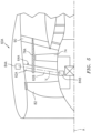
FIG. 2 is a schematic illustration of the high bypass gas turbine engine with an after-fan system according to one disclosed non-limiting embodiment. -
FIG. 3 is a schematic illustration of an operational range of a variable guide vane array upstream of the after-fan turbine of the after-fan system. -
FIG. 4 is a schematic illustration of an airflow angle range through the after-fan system. -
FIG. 5 is a schematic illustration of the high bypass gas turbine engine with an after-fan system with a splitter and a short span after-fan turbine according to another disclosed non-limiting embodiment. -
FIG. 6 is a schematic illustration of a low bypass gas turbine engine with an after-fan system according to one disclosed non-limiting embodiment. -
FIG. 7 is a schematic illustration of the low bypass gas turbine engine with an after-fan system with a splitter and a short span after-fan turbine according to another disclosed non-limiting embodiment. -
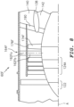
FIG. 8 is a schematic illustration of the low bypass gas turbine engine with an extended splitter and short span after-fan system with a full span variable vane array according to another disclosed non-limiting embodiment. -
FIG. 1 schematically illustrates agas turbine engine 20. Thegas turbine engine 20 is disclosed herein as a two-spool turbofan that generally incorporates afan section 22, acompressor section 24, acombustor section 26, and aturbine section 28. Thefan section 22 drives air along a bypass flowpath B while thecompressor section 24 drives air along a core flow combustion gas path C for compression and communication into thecombustor section 26, then expansion through theturbine section 28. The fan, compressor, and turbine sections may include various architectures that, for example, include a multitude of stages, each with or without various combinations of variable or fixed guide vanes. The sections are defined along a central longitudinal engine axis A. Although depicted as a turbofan in the disclosed non-limiting embodiment, it should be appreciated that the concepts described herein may be applied to other engine architectures such as turbojets, turboshafts, and three-spool (plus fan) turbofans. - The
engine 20 generally includes alow spool 30 and ahigh spool 32 mounted for rotation about an engine central longitudinal axis A relative to an enginestatic structure 36 viaseveral bearings 38. Thelow spool 30 generally includes aninner shaft 40 that interconnects afan section 42, a low pressure compressor ("LPC") 44 and a low pressure turbine ("LPT") 46. Theinner shaft 40 drives thefan section 42 directly or through a gearedarchitecture 48 that drives thefan section 42 at a lower speed than thelow spool 30. An exemplary reduction transmission is an epicyclic transmission, such as a planetary or star gear system. - The
high spool 32 includes anouter shaft 50 that interconnects a high pressure compressor ("HPC") 52 and high pressure turbine ("HPT") 54. Acombustor 56 is arranged between thehigh pressure compressor 52 and thehigh pressure turbine 54. Theinner shaft 40 and theouter shaft 50 are concentric and rotate about the engine central longitudinal axis A which is collinear with their longitudinal axes. - Core airflow is compressed by the
LPC 44, then the HPC 52, mixed with the fuel and burned in thecombustor 56, then expanded over the HPT 54 and theLPT 46 which rotationally drive the respectivehigh spool 32 and thelow spool 30 in response to the expansion. Themain engine shafts bearings 38 within thestatic structure 36. - In one non-limiting embodiment, the
gas turbine engine 20 is a high-bypass geared architecture engine in which the bypass ratio is greater than six (6:1). The gearedarchitecture 48 can include an epicyclic gear train, such as a planetary gear system, star gear system or other gear system. The example epicyclic gear train has a gear reduction ratio of greater than 2.3, and in another example is greater than 2.5. The geared turbofan enables operation of thelow spool 30 at higher speeds which can increase the operational efficiency of thelow pressure compressor 44 andlow pressure turbine 46 and render increased pressure in a fewer number of stages. - A pressure ratio associated with the
low pressure turbine 46 is pressure measured prior to the inlet of thelow pressure turbine 46 as related to the pressure at the outlet of thelow pressure turbine 46 prior to an exhaust nozzle of thegas turbine engine 20. In one non-limiting embodiment, the bypass ratio of thegas turbine engine 20 is greater than ten (10:1), the fan diameter is significantly larger than that of thelow pressure compressor 44, and thelow pressure turbine 46 has a pressure ratio that is greater than five (5:1). It should be appreciated, however, that the above parameters are only exemplary of one embodiment of a geared architecture engine and that the present disclosure is applicable to other gas turbine engines including direct drive turbofans. - The high bypass ratio results in a significant amount of thrust. The
fan section 22 of thegas turbine engine 20 is designed for a particular flight condition - typically cruise at 0.8 Mach and 35,000 feet. This flight condition, with thegas turbine engine 20 at its best fuel consumption, is also known as bucket cruise Thrust Specific Fuel Consumption (TSFC). TSFC is an industry standard parameter of fuel consumption per unit of thrust. - Fan Pressure Ratio is the pressure ratio across a blade of the
fan section 22 without the use of a fan exit guide vane system. The low Fan Pressure Ratio according to one non-limiting embodiment of the examplegas turbine engine 20 is less than 1.45. Low Corrected Fan Tip Speed is the actual fan tip speed divided by an industry standard temperature correction of ("T" / 518.7)0.5. The Low Corrected Fan Tip Speed according to one non-limiting embodiment of the examplegas turbine engine 20 is less than 1150 fps (351 m/s). The Low Corrected Fan Tip Speed in another non-limiting embodiment of the examplegas turbine engine 20 is less than 1200 fps (366 m/s). - With reference to
FIG. 2 , thefan section 22 includes an after-fan system 60 downstream of thefan section 42. The after-fan system 60 includes a variable pitch fan exitguide vane array 62 that form a variable pitch fan exitguide vane ring 64 transverse to the bypass flowpath between anouter profile 66 of a corestatic structure 68 and aninner periphery 70 of thefan nacelle 72. Downstream of the variable pitch fan exitguide vane ring 64, an after-fan turbine 74 is positioned between theouter profile 66 of the corestatic structure 68 and aring splitter 76 located radially inboard of theinner periphery 70 of thefan nacelle 72. In this embodiment, the after-fan turbine 74 is a short span after-fan turbine 74 which is contained within thering splitter 76. Thering splitter 76 may be at least partially supported by an array ofstruts 78 between theouter profile 66 of the corestatic structure 68 and theinner periphery 70 of thefan nacelle 72. - The after-
fan turbine 74 rotates about the engine centerline axis A. The after-fan turbine 74 may be driven at speed related to thefan section 42 either directly or through the gearedarchitecture 48. The after-fan turbine 74 extracts a portion of the energy from the compressed bypass flow from thefan section 42 and returns energy to thefan section 42 through torque. The after-fan turbine 74 includes after-fan turbine blades 80 that, in this embodiment, are of a span less than thefan blades 82 of thefan section 42. In one example, the after-fan turbine 74 is of a diameter between 50%-75% of thefan section 42. The stagger angles of the after-fan turbine blades 80 andfan blades 82 are the angle of the chord line connecting the tip of the airfoil shape to the trailing edge of the airfoil shape. Measured between the direction of the wheel speed, U, and the chord line, the stagger angles of the after-fan turbine blades 80 andfan blades 82 are substantially the same. The chord length of thefan blades 82 is substantially longer than the chord length of the after-fan turbine blades 80 due to the different aerodynamic loadings of thefan blades 82 versus the after-fan turbine blades 80. The relative velocity, W, of the flow passing over thefan blades 82 decelerates and creates a higher aerodynamic loading. The relative velocity, W, of the flow passing over after-fan turbine blades 80 accelerates from W1 to W2 and the aerodynamic loading is lower than thefan blades 82. The aerodynamic loading of the after-fan turbine blades 80 varies with thevane 62 angle, alpha1. Decreasing alpha1 increases the aerodynamic loading of the after-fan turbine blades 80. - A pitch angle of each of the variable pitch fan exit
guide vane array 62 may be varied along a pitch axis V to change the pitch thereof in response to acontroller 100 to modify the bypass airflow from thefan section 42 that is communicated into the after-fan turbine 74. Thecontroller 100 generally may include a processor, a memory, and an interface. The processor may be any type of microprocessor having desired performance characteristics. The processor and the interface are communicatively coupled to the memory. The memory may be embodied as any type of computer memory device which stores data and control algorithms such as logic as described herein. The interface is communicatively coupled to a number of hardware, firmware, and/or software components, including sensors and actuators 84 for the variable pitch fan exitguide vane array 62. Thecontroller 100 may, for example, be a portion of a flight control computer, a portion of a Full Authority Digital Engine Control (FADEC), a stand-alone unit or combinations thereof. - The variable pitch fan exit
guide vane array 62 modifies the bypass airflow from the fan section 42 (FIG. 3 ) such that a bypass airflow entrance angle into the after-fan turbine 74 is selectively adjusted to change the energy extracted therefrom to, for example, maximize energy extraction at cruise, yet minimize energy extraction at the top of climb and take-off thrust conditions. - The variable pitch fan exit
guide vane array 62 and the after-fan turbine 74 controls a fan operating line for efficiency and operability at the desired flight conditions. The after-fan turbine 74 optimizesfan duct nozzle 88 pressure ratio, andnozzle 88 exit airflow velocity, accordingly, to increase propulsive efficiency at different off-design flight conditions. The short span after-fan system 60 is of reduced weight and provides design flexibility to create an aerodynamically efficient afterfan turbine 74 by design choices of rpm and diameter optimization for achieving engine thrust requirements. - To decrease engine specific fuel consumption (TSFC) engine propulsive efficiency is increased, which is associated with very low cruise fan pressure ratio of about 1.15, and a super high engine bypass ratio of about 20 vs. current industry cruise at a fan pressure ratio of about 1.35 and engine bypass ratio of about 11. Current engines have a top of climb (for max available thrust) fan pressure ratio of about 1.5.
- In one embodiment, the variable pitch fan exit
guide vane array 62 are movable (FIG. 4 ) between a maximum powerextraction pitch position 110 for the after-fan system 60 typically utilized at cruise thrust conditions and a minimum powerextraction pitch position 112 typically utilized for max climb engine power setting, top of climb, and at take-off thrust conditions as represented by the airflow vectors triangles. The after-fan system 60 permits the fan diameter of thefan section 42 to be sized for cruise thrust conditions which results in one example of an about 6% TSFC advantage. The after-fan system 60 also permits an increase to the max available fan pressure ratio for the top of climb, and at take-off thrust conditions. This provides a decrease in overall engine weight with a reduced diameter to facilitate underwing nacelle installation. In this embodiment, thefan section 42 and the after-fan turbine 74 rotate in the same direction, however, counter-rotating systems may also be provided. - With reference to
FIG. 3 and 4 , example ranges of the airflow vector angles in the airflow vectors triangles include: - α0 - the airflow local angle at vane leading edge of 30-60 degrees. This angle is the resulting airflow swirl downstream of the
fan section 42 at different fan rpm. - α1 - the airflow C1 speed vector angle at a trailing edge of the variable pitch fan exit
guide vane array 62 of 30-60 degrees. This is the vane exit speed vector that is the resulting airflow turning by the vane airfoils channel. - β1 - the airflow local W1 speed vector angle of about 20-50 degrees at the leading edge of the after-
fan turbine 74, which is resulting vector in triangle with C1 vector and the U vector which represents the after-fan turbine 74 rotational speed. - β2 - the airflow W2 speed vector of about 20-40 degrees at the trailing edge of the after-fan turbine 74 (turbine blades channel exit).
- These ranges may vary depending on, for example, turbine blade section arrangements along turbine vane span, after-fan blade geometry, anticipated turbine expansion ratios for the embodiment, turbine rpm, and turbine blade profiles. For this high swirl version fan, the existed high fan airflow swirl create condition to use the swirl to improve variable vane efficiency and design when using contra rotating version. For contra rotating versions, vane and turbine blades profiles will have mirrored arrangement vs. considered in
Fig. 3 and 4 vector triangles. Further, the after-fan turbine blades may have different aerodynamic loading profiles along blades span with a minimum turbine expansion ratio in a root portion of the blade, which faces core flow path. - With reference to
FIG. 5 , another embodiment of the after-fan system 60A includes a variable pitch fan exitguide vane ring 64A upstream of the after-fan turbine 74A. The variable pitch fan exitguide vane ring 64A includes anouter diameter portion 62A of the variable pitch fan exitguide vane ring 64A and aninner diameter portion 62B of the variable pitch fan exitguide vane ring 64A. Theouter diameter portion 62A and theinner diameter portion 62B may be independently adjusted in pitch about the common pitch axis V by arespective actuator outer diameter portion 62A or theinner diameter portion 62B may be fixed to at least partially supports thering splitter 76A. Alternatively, thering splitter 76A may be partially supported by astrut array 90. In this embodiment, the after-fan turbine 74 is contained within thering splitter 76A. This enables the portion of the bypass flow B in theouter diameter portion 62A to be adjusted in flow rate and pressure independently of the portion of the bypass flow B in theinner diameter portion 62B in response toengine 20 fuel flow changes that varyengine 20 thrust as between a cruise and climb condition. The short blade span turbine splitter provides advantage for turbine blade tip clearance to facilitate efficiency. - With reference to
FIG. 6 , another embodiment of the after-fan system 60D is utilized with a low-bypassgas turbine engine 120. Thegas turbine engine 120 is disclosed herein as a two-spool, low-bypass, augmented turbofan that generally incorporates afan section 122, acompressor section 124, acombustor section 126, aturbine section 128, anaugmenter section 130, aduct section 132, and anozzle system 134 along a central longitudinal engine axis A. Although generally described and illustrated with regard to a low-bypass gas turbine engine, a variable cycle gas turbine engine that essentially alters a bypass ratio during flight to achieve countervailing objectives such as high specific thrust for high-energy maneuvers yet optimizes fuel efficiency for cruise and loiter operational modes will also benefit herefrom. - An
outer case structure 136 and aninner case structure 138 define a generally annularsecondary airflow path 140 around acore airflow path 142. Various structures may define theouter case structure 136 and theinner case structure 138 which essentially define an exoskeleton to support rotational hardware therein. Air that enters thefan section 122 is divided between core airflow through thecore airflow path 142, and secondary airflow through thesecondary airflow path 140. The core airflow passes through thecombustor section 126, theturbine section 128, then theaugmentor section 130, where fuel may be selectively injected and burned to generate additional thrust through thenozzle system 134. - The secondary airflow may be utilized for a multiple of purposes to include, for example, cooling, pressurization and variable cycle operations. The secondary airflow as defined herein is any airflow different from the core airflow. The secondary airflow may ultimately be at least partially injected into the
core airflow path 142 adjacent to theduct section 132 and thenozzle system 134. - With reference to
FIG. 7 , in this embodiment, the after-fan system 60D includes a split variable pitch fan exitguide vane ring 164D upstream of an after-fan turbine 174D that is upstream of thesecondary airflow path 140 and thecore airflow path 142. The split variable pitch fan exitguide vane ring 164D includes an outer diameter portion of the variable pitchfan exit guide 162A and asecond vane portion 162B that partially supports thering splitter 176D. The outer diameter portion of the variable pitchfan exit guide 162A and/or thesecond vane portion 162B may be individually or collectively varied in pitch to selectively control the airflow to the after-fan turbine 174D within thering splitter 176D. The ring splitter 176A is located radially intermediate thesecondary airflow path 140. Architectures with two portion variable pitch exit guide vanes that facilitate control of turbine power extraction by inner portion airflow vector changes in front of the turbine blade leading edge, and at the same time controls a fan operating line. - With reference to
FIG. 8 , another embodiment of the after-fan system 60F includes a split variable pitch fan exitguide vane ring 164F upstream of a short span after-fan turbine 174F that is upstream of thesecondary airflow path 140 and thecore airflow path 142. The split variable pitch fan exitguide vane ring 164F includes an outer diameter portion 162Fa and a inner diameter portion 162Fb that partially supports thering splitter 176F. The outer diameter portion 162Fa and/or the inner diameter portion 162Fb may be individually or collectively varied in pitch to selectively control the airflow to the after-fan turbine 174F within thering splitter 176F. In this embodiment, thering splitter 176F is located radially intermediate thesecondary airflow path 140 and encompasses alow pressure compressor 124A of thecompressor section 124. That is, thefan section 122 and the split variable pitch fan exitguide vane ring 164F extend radially beyond thering splitter 176F. Thering splitter 176F is also at least partially supported by astrut array 190 which spans thesecondary airflow path 140 and thecore airflow path 142 to at least partially support theinner case structure 138. - The split variable pitch fan exit
guide vane ring 164F permits independent control of the outer diameter portion 162Fa and the second vane portion 162Fb. The outer diameter portion 162Fa facilitates control of the fan operational line for best efficiency and stability margin, and at the inner diameter portion 162Fb facilitates the required power extraction and efficiency for the short span after-fan turbine 174F. The outer diameter portion 162Fa also facilitates a change in an adaptive fan outer airflow to optimized BPR for different flight segments. The axiallyextended ring splitter 176F facilitates formation of a third stream by splitter extension downstream of the fan duct. Architectures with short span blades facilitates the generation of the third stream by splitter extension downstream of the duct to optimize engine bypass ratio for different flights segments. - The foregoing description is exemplary rather than defined by the limitations within. Various non-limiting embodiments are disclosed herein, however, one of ordinary skill in the art would recognize that various modifications and variations in light of the above teachings will fall within the scope of the appended claims. It is therefore to be appreciated that within the scope of the appended claims, the disclosure may be practiced other than as specifically described. For that reason, the appended claims should be studied to determine true scope and content.
Claims (12)
- An after-fan system for a gas turbine engine, comprising:a variable pitch fan exit guide vane array (62); and a control (100) operable to vary a pitch of the variable fan exit guide vane array (62);characterized in comprisinga short span after-fan turbine (74) downstream of the variable pitch fan exit guide vane array (62) and upstream of a bypass or secondary airflow path (B, 140) and a core airflow path (C, 142), the short span after-fan turbine (74) being positioned between an outer profile (66) of a core static structure (68) and a ring splitter (76) located radially inboard of an inner periphery (70) of a fan nacelle or outer case structure (72, 136), the short span after-fan turbine (74) being contained radially within the ring splitter (76).
- The after-fan system as recited in claim 1, wherein the variable pitch fan exit guide vane array (62) comprises a split variable pitch fan exit guide vane array (62A, 62B).
- The after-fan system as recited in claim 2, wherein the split variable pitch fan exit guide vane array (62) includes a first variable pitch fan exit guide vane array (62A) and a second variable pitch fan exit guide vane array (62B) inboard of the first variable pitch fan exit guide vane array (62A).
- The after-fan system as recited in claim 3, wherein the first variable pitch fan exit guide vane array (62A) and the second variable pitch fan exit guide vane array (62B) are independently adjustable in pitch.
- The after-fan system as recited in claim 3 or 4, wherein the first variable pitch fan exit guide vane array (62A) and the second variable pitch fan exit guide vane array (62B) are separated by a splitter (76A).
- The after-fan system as recited in claim 5, wherein the after-fan turbine (74, 174G) is located within the splitter (76).
- The after-fan system as recited in any preceding claim, wherein the variable pitch fan exit guide vane array (62) is downstream of a fan section (42).
- The after-fan system as recited in any preceding claim, wherein the bypass or secondary airflow path (B, 140) is defined between the fan nacelle or outer case structure (72, 136) and an inner case structure (138), the inner case structure being defined around the core airflow path (C, 142).
- A method of generating thrust for a gas turbine engine, comprising:rotating a fan section (42) with an array of fan blades (82);rotating a short span after-fan turbine (74) downstream of the fan section (42) and upstream of a bypass or secondary airflow path (B, 140) and a core airflow path (C, 142), the short span after-fan turbine (74) being positioned between an outer profile (66) of a core static structure (68) and a ring splitter (76) located radially inboard of an inner periphery (70) of a fan nacelle or outer case structure (72, 136), the short span after-fan turbine (74) being contained radially within the ring splitter (76); andvarying a pitch of a variable fan exit guide vane array (62) downstream of the fan section (42) and upstream of the after-fan turbine (74).
- The method as recited in claim 9, wherein varying the pitch of the variable fan exit guide vane array (62) comprises independently varying a pitch of an outer diameter section of the variable fan exit guide vane array (62A) and an inner diameter section of the variable fan exit guide vane array (62B).
- The method as recited in claim 9 or 10, further comprising locating a splitter (76A) between the outer diameter section of the variable fan exit guide vane array (62A) and the inner diameter section of the variable fan exit guide vane array (62B).
- The method as recited in claim 9, 10 or 11, wherein the bypass or secondary airflow path (B, 140) is defined between the fan nacelle or outer case structure (72, 136) and an inner case structure (138), the inner case structure being defined around the core airflow path (C, 142).
Applications Claiming Priority (1)
| Application Number | Priority Date | Filing Date | Title |
|---|---|---|---|
| US201962831953P | 2019-04-10 | 2019-04-10 |
Publications (2)
| Publication Number | Publication Date |
|---|---|
| EP3722565A1 EP3722565A1 (en) | 2020-10-14 |
| EP3722565B1 true EP3722565B1 (en) | 2025-02-12 |
Family
ID=70227794
Family Applications (1)
| Application Number | Title | Priority Date | Filing Date |
|---|---|---|---|
| EP20168376.0A Active EP3722565B1 (en) | 2019-04-10 | 2020-04-07 | After-fan system for a gas turbine engine |
Country Status (2)
| Country | Link |
|---|---|
| US (1) | US11994089B2 (en) |
| EP (1) | EP3722565B1 (en) |
Families Citing this family (8)
| Publication number | Priority date | Publication date | Assignee | Title |
|---|---|---|---|---|
| US11846196B2 (en) | 2020-02-21 | 2023-12-19 | Rtx Corporation | After-fan system with electrical motor for gas turbine engines |
| US11781506B2 (en) * | 2020-06-03 | 2023-10-10 | Rtx Corporation | Splitter and guide vane arrangement for gas turbine engines |
| FR3118094A1 (en) * | 2020-12-23 | 2022-06-24 | Safran | STATOR BLADE WITH MOBILE PORTION, TURBOMACHINE MODULE EQUIPPED WITH SUCH A STATOR BLADE AND CORRESPONDING TURBOMACHINE |
| US12037921B2 (en) * | 2022-08-04 | 2024-07-16 | General Electric Company | Fan for a turbine engine |
| EP4630658A1 (en) * | 2022-12-05 | 2025-10-15 | Safran Aircraft Engines | Triple-flow aircraft turbomachine |
| US12338743B1 (en) | 2023-12-21 | 2025-06-24 | General Electric Company | Gas turbine engines having moveable inlet guide vanes and stator vanes |
| US12312966B1 (en) * | 2024-06-05 | 2025-05-27 | Rtx Corporation | Gas turbine engine with hybrid fan exit guide vanes |
| US20250376990A1 (en) * | 2024-06-05 | 2025-12-11 | Rtx Corporation | Gas turbine engine with split variable fan exit guide vanes and airflow radial total pressure profile re-distribution |
Citations (2)
| Publication number | Priority date | Publication date | Assignee | Title |
|---|---|---|---|---|
| US6209311B1 (en) * | 1998-04-13 | 2001-04-03 | Nikkiso Company, Ltd. | Turbofan engine including fans with reduced speed |
| US20110167792A1 (en) * | 2009-09-25 | 2011-07-14 | James Edward Johnson | Adaptive engine |
Family Cites Families (15)
| Publication number | Priority date | Publication date | Assignee | Title |
|---|---|---|---|---|
| GB1497477A (en) * | 1975-07-19 | 1978-01-12 | Rolls Royce | Gas turbine engine |
| US4222233A (en) * | 1977-08-02 | 1980-09-16 | General Electric Company | Auxiliary lift propulsion system with oversized front fan |
| FR2461820A1 (en) | 1979-07-16 | 1981-02-06 | Snecma | MULTIFLUX TURBOREACTOR WITH A DILUTION RATE |
| US5261227A (en) | 1992-11-24 | 1993-11-16 | General Electric Company | Variable specific thrust turbofan engine |
| US7614210B2 (en) | 2006-02-13 | 2009-11-10 | General Electric Company | Double bypass turbofan |
| US7849669B2 (en) | 2006-08-28 | 2010-12-14 | Rory Keogh | Turbofan engine utilizing an aerodynamically coupled pre-combustion power turbine |
| US10151248B2 (en) * | 2007-10-03 | 2018-12-11 | United Technologies Corporation | Dual fan gas turbine engine and gear train |
| US8777554B2 (en) * | 2009-12-21 | 2014-07-15 | General Electric Company | Intermediate fan stage |
| US20110146289A1 (en) * | 2009-12-21 | 2011-06-23 | John Lewis Baughman | Power extraction method |
| US20110146228A1 (en) * | 2009-12-21 | 2011-06-23 | John Lewis Baughman | Power extraction system |
| US8935923B2 (en) | 2011-10-25 | 2015-01-20 | United Technologies Corporation | Gas turbine engine with intercooling turbine section and intercooling turbine section bypass |
| US20130104522A1 (en) * | 2011-11-01 | 2013-05-02 | Daniel B. Kupratis | Gas turbine engine with variable pitch first stage fan section |
| EP2971649A4 (en) | 2013-03-14 | 2016-03-16 | United Technologies Corp | GAS TURBINE ENGINE ARCHITECTURE HAVING CONCENTRIC NITROGEN COMBUSTION CHAMBERS |
| DE102015209892A1 (en) | 2015-05-29 | 2016-12-01 | Rolls-Royce Deutschland Ltd & Co Kg | Adaptive aircraft engine and aircraft with an adaptive engine |
| FR3043714B1 (en) | 2015-11-16 | 2017-12-22 | Snecma | FRONT AIRCRAFT TURBOMACHINE PART COMPRISING A SINGLE BLOWER CONDUCTED BY A REDUCER, AS WELL AS STRUCTURAL OUTPUT LEAD DIRECTORS FITTED PARTLY BEFORE A SEPARATION SPOUT |
-
2020
- 2020-04-01 US US16/837,143 patent/US11994089B2/en active Active
- 2020-04-07 EP EP20168376.0A patent/EP3722565B1/en active Active
Patent Citations (2)
| Publication number | Priority date | Publication date | Assignee | Title |
|---|---|---|---|---|
| US6209311B1 (en) * | 1998-04-13 | 2001-04-03 | Nikkiso Company, Ltd. | Turbofan engine including fans with reduced speed |
| US20110167792A1 (en) * | 2009-09-25 | 2011-07-14 | James Edward Johnson | Adaptive engine |
Also Published As
| Publication number | Publication date |
|---|---|
| US20200325852A1 (en) | 2020-10-15 |
| EP3722565A1 (en) | 2020-10-14 |
| US11994089B2 (en) | 2024-05-28 |
Similar Documents
| Publication | Publication Date | Title |
|---|---|---|
| EP3722565B1 (en) | After-fan system for a gas turbine engine | |
| US11970984B2 (en) | Gas turbine engine with power density range | |
| EP3564507B1 (en) | Gas turbine engine inlet | |
| EP3108106B1 (en) | Gas turbine engine airfoil | |
| EP3825538B1 (en) | Variable area fan nozzle bearing track | |
| US9790861B2 (en) | Gas turbine engine having support structure with swept leading edge | |
| EP3108118B1 (en) | Gas turbine engine airfoil | |
| WO2014042698A1 (en) | Geared turbofan engine with power density range | |
| US11555420B1 (en) | Frame connection between fan case and core housing in a gas turbine engine | |
| EP3604741B1 (en) | Turbomachinery transition duct for wide bypass ratio ranges | |
| WO2014031182A1 (en) | Geared turbofan engine with power density range | |
| US10704415B2 (en) | Gas turbine engine with low fan noise | |
| EP4155519A2 (en) | Geared gas turbine engine with front section moment stiffness relationships | |
| EP3108105B1 (en) | Gas turbine engine airfoil | |
| EP4180637B1 (en) | Gas turbine engine with triangular-frame connection between fan case and core housing | |
| US11773866B2 (en) | Repeating airfoil tip strong pressure profile | |
| CA2916866C (en) | Geared turbofan engine with power density range | |
| US12098681B2 (en) | High and low spool configuration for a gas turbine engine | |
| EP4137688B1 (en) | Front section stiffness ratio | |
| US20260103995A1 (en) | Turbine engine having a fan speed sensor system | |
| CA2915343A1 (en) | Geared turbofan engine with a high ratio of thrust to turbine volume |
Legal Events
| Date | Code | Title | Description |
|---|---|---|---|
| PUAI | Public reference made under article 153(3) epc to a published international application that has entered the european phase |
Free format text: ORIGINAL CODE: 0009012 |
|
| STAA | Information on the status of an ep patent application or granted ep patent |
Free format text: STATUS: THE APPLICATION HAS BEEN PUBLISHED |
|
| AK | Designated contracting states |
Kind code of ref document: A1 Designated state(s): AL AT BE BG CH CY CZ DE DK EE ES FI FR GB GR HR HU IE IS IT LI LT LU LV MC MK MT NL NO PL PT RO RS SE SI SK SM TR |
|
| AX | Request for extension of the european patent |
Extension state: BA ME |
|
| STAA | Information on the status of an ep patent application or granted ep patent |
Free format text: STATUS: REQUEST FOR EXAMINATION WAS MADE |
|
| 17P | Request for examination filed |
Effective date: 20210414 |
|
| RBV | Designated contracting states (corrected) |
Designated state(s): AL AT BE BG CH CY CZ DE DK EE ES FI FR GB GR HR HU IE IS IT LI LT LU LV MC MK MT NL NO PL PT RO RS SE SI SK SM TR |
|
| STAA | Information on the status of an ep patent application or granted ep patent |
Free format text: STATUS: EXAMINATION IS IN PROGRESS |
|
| 17Q | First examination report despatched |
Effective date: 20220725 |
|
| RAP3 | Party data changed (applicant data changed or rights of an application transferred) |
Owner name: RTX CORPORATION |
|
| GRAP | Despatch of communication of intention to grant a patent |
Free format text: ORIGINAL CODE: EPIDOSNIGR1 |
|
| STAA | Information on the status of an ep patent application or granted ep patent |
Free format text: STATUS: GRANT OF PATENT IS INTENDED |
|
| INTG | Intention to grant announced |
Effective date: 20240904 |
|
| GRAS | Grant fee paid |
Free format text: ORIGINAL CODE: EPIDOSNIGR3 |
|
| GRAA | (expected) grant |
Free format text: ORIGINAL CODE: 0009210 |
|
| STAA | Information on the status of an ep patent application or granted ep patent |
Free format text: STATUS: THE PATENT HAS BEEN GRANTED |
|
| AK | Designated contracting states |
Kind code of ref document: B1 Designated state(s): AL AT BE BG CH CY CZ DE DK EE ES FI FR GB GR HR HU IE IS IT LI LT LU LV MC MK MT NL NO PL PT RO RS SE SI SK SM TR |
|
| REG | Reference to a national code |
Ref country code: GB Ref legal event code: FG4D |
|
| REG | Reference to a national code |
Ref country code: CH Ref legal event code: EP |
|
| REG | Reference to a national code |
Ref country code: DE Ref legal event code: R096 Ref document number: 602020045797 Country of ref document: DE |
|
| REG | Reference to a national code |
Ref country code: IE Ref legal event code: FG4D |
|
| REG | Reference to a national code |
Ref country code: NL Ref legal event code: MP Effective date: 20250212 |
|
| PG25 | Lapsed in a contracting state [announced via postgrant information from national office to epo] |
Ref country code: RS Free format text: LAPSE BECAUSE OF FAILURE TO SUBMIT A TRANSLATION OF THE DESCRIPTION OR TO PAY THE FEE WITHIN THE PRESCRIBED TIME-LIMIT Effective date: 20250512 |
|
| PG25 | Lapsed in a contracting state [announced via postgrant information from national office to epo] |
Ref country code: FI Free format text: LAPSE BECAUSE OF FAILURE TO SUBMIT A TRANSLATION OF THE DESCRIPTION OR TO PAY THE FEE WITHIN THE PRESCRIBED TIME-LIMIT Effective date: 20250212 |
|
| PG25 | Lapsed in a contracting state [announced via postgrant information from national office to epo] |
Ref country code: PL Free format text: LAPSE BECAUSE OF FAILURE TO SUBMIT A TRANSLATION OF THE DESCRIPTION OR TO PAY THE FEE WITHIN THE PRESCRIBED TIME-LIMIT Effective date: 20250212 |
|
| PGFP | Annual fee paid to national office [announced via postgrant information from national office to epo] |
Ref country code: DE Payment date: 20250319 Year of fee payment: 6 |
|
| PG25 | Lapsed in a contracting state [announced via postgrant information from national office to epo] |
Ref country code: ES Free format text: LAPSE BECAUSE OF FAILURE TO SUBMIT A TRANSLATION OF THE DESCRIPTION OR TO PAY THE FEE WITHIN THE PRESCRIBED TIME-LIMIT Effective date: 20250212 |
|
| REG | Reference to a national code |
Ref country code: LT Ref legal event code: MG9D |
|
| PG25 | Lapsed in a contracting state [announced via postgrant information from national office to epo] |
Ref country code: IS Free format text: LAPSE BECAUSE OF FAILURE TO SUBMIT A TRANSLATION OF THE DESCRIPTION OR TO PAY THE FEE WITHIN THE PRESCRIBED TIME-LIMIT Effective date: 20250612 Ref country code: NO Free format text: LAPSE BECAUSE OF FAILURE TO SUBMIT A TRANSLATION OF THE DESCRIPTION OR TO PAY THE FEE WITHIN THE PRESCRIBED TIME-LIMIT Effective date: 20250512 |
|
| PG25 | Lapsed in a contracting state [announced via postgrant information from national office to epo] |
Ref country code: NL Free format text: LAPSE BECAUSE OF FAILURE TO SUBMIT A TRANSLATION OF THE DESCRIPTION OR TO PAY THE FEE WITHIN THE PRESCRIBED TIME-LIMIT Effective date: 20250212 |
|
| PG25 | Lapsed in a contracting state [announced via postgrant information from national office to epo] |
Ref country code: HR Free format text: LAPSE BECAUSE OF FAILURE TO SUBMIT A TRANSLATION OF THE DESCRIPTION OR TO PAY THE FEE WITHIN THE PRESCRIBED TIME-LIMIT Effective date: 20250212 |
|
| PG25 | Lapsed in a contracting state [announced via postgrant information from national office to epo] |
Ref country code: LV Free format text: LAPSE BECAUSE OF FAILURE TO SUBMIT A TRANSLATION OF THE DESCRIPTION OR TO PAY THE FEE WITHIN THE PRESCRIBED TIME-LIMIT Effective date: 20250212 Ref country code: PT Free format text: LAPSE BECAUSE OF FAILURE TO SUBMIT A TRANSLATION OF THE DESCRIPTION OR TO PAY THE FEE WITHIN THE PRESCRIBED TIME-LIMIT Effective date: 20250612 |
|
| PG25 | Lapsed in a contracting state [announced via postgrant information from national office to epo] |
Ref country code: BG Free format text: LAPSE BECAUSE OF FAILURE TO SUBMIT A TRANSLATION OF THE DESCRIPTION OR TO PAY THE FEE WITHIN THE PRESCRIBED TIME-LIMIT Effective date: 20250212 Ref country code: GR Free format text: LAPSE BECAUSE OF FAILURE TO SUBMIT A TRANSLATION OF THE DESCRIPTION OR TO PAY THE FEE WITHIN THE PRESCRIBED TIME-LIMIT Effective date: 20250513 |
|
| REG | Reference to a national code |
Ref country code: AT Ref legal event code: MK05 Ref document number: 1766210 Country of ref document: AT Kind code of ref document: T Effective date: 20250212 |
|
| PG25 | Lapsed in a contracting state [announced via postgrant information from national office to epo] |
Ref country code: SE Free format text: LAPSE BECAUSE OF FAILURE TO SUBMIT A TRANSLATION OF THE DESCRIPTION OR TO PAY THE FEE WITHIN THE PRESCRIBED TIME-LIMIT Effective date: 20250212 |
|
| PG25 | Lapsed in a contracting state [announced via postgrant information from national office to epo] |
Ref country code: SM Free format text: LAPSE BECAUSE OF FAILURE TO SUBMIT A TRANSLATION OF THE DESCRIPTION OR TO PAY THE FEE WITHIN THE PRESCRIBED TIME-LIMIT Effective date: 20250212 |
|
| PG25 | Lapsed in a contracting state [announced via postgrant information from national office to epo] |
Ref country code: DK Free format text: LAPSE BECAUSE OF FAILURE TO SUBMIT A TRANSLATION OF THE DESCRIPTION OR TO PAY THE FEE WITHIN THE PRESCRIBED TIME-LIMIT Effective date: 20250212 |
|
| PG25 | Lapsed in a contracting state [announced via postgrant information from national office to epo] |
Ref country code: IT Free format text: LAPSE BECAUSE OF FAILURE TO SUBMIT A TRANSLATION OF THE DESCRIPTION OR TO PAY THE FEE WITHIN THE PRESCRIBED TIME-LIMIT Effective date: 20250212 |
|
| PG25 | Lapsed in a contracting state [announced via postgrant information from national office to epo] |
Ref country code: AT Free format text: LAPSE BECAUSE OF FAILURE TO SUBMIT A TRANSLATION OF THE DESCRIPTION OR TO PAY THE FEE WITHIN THE PRESCRIBED TIME-LIMIT Effective date: 20250212 |
|
| PG25 | Lapsed in a contracting state [announced via postgrant information from national office to epo] |
Ref country code: EE Free format text: LAPSE BECAUSE OF FAILURE TO SUBMIT A TRANSLATION OF THE DESCRIPTION OR TO PAY THE FEE WITHIN THE PRESCRIBED TIME-LIMIT Effective date: 20250212 Ref country code: CZ Free format text: LAPSE BECAUSE OF FAILURE TO SUBMIT A TRANSLATION OF THE DESCRIPTION OR TO PAY THE FEE WITHIN THE PRESCRIBED TIME-LIMIT Effective date: 20250212 |
|
| PG25 | Lapsed in a contracting state [announced via postgrant information from national office to epo] |
Ref country code: RO Free format text: LAPSE BECAUSE OF FAILURE TO SUBMIT A TRANSLATION OF THE DESCRIPTION OR TO PAY THE FEE WITHIN THE PRESCRIBED TIME-LIMIT Effective date: 20250212 |
|
| PG25 | Lapsed in a contracting state [announced via postgrant information from national office to epo] |
Ref country code: SK Free format text: LAPSE BECAUSE OF FAILURE TO SUBMIT A TRANSLATION OF THE DESCRIPTION OR TO PAY THE FEE WITHIN THE PRESCRIBED TIME-LIMIT Effective date: 20250212 |
|
| REG | Reference to a national code |
Ref country code: DE Ref legal event code: R097 Ref document number: 602020045797 Country of ref document: DE |
|
| REG | Reference to a national code |
Ref country code: CH Ref legal event code: H13 Free format text: ST27 STATUS EVENT CODE: U-0-0-H10-H13 (AS PROVIDED BY THE NATIONAL OFFICE) Effective date: 20251125 |
|
| PG25 | Lapsed in a contracting state [announced via postgrant information from national office to epo] |
Ref country code: LU Free format text: LAPSE BECAUSE OF NON-PAYMENT OF DUE FEES Effective date: 20250407 |
|
| PLBE | No opposition filed within time limit |
Free format text: ORIGINAL CODE: 0009261 |
|
| STAA | Information on the status of an ep patent application or granted ep patent |
Free format text: STATUS: NO OPPOSITION FILED WITHIN TIME LIMIT |
|
| PG25 | Lapsed in a contracting state [announced via postgrant information from national office to epo] |
Ref country code: MC Free format text: LAPSE BECAUSE OF FAILURE TO SUBMIT A TRANSLATION OF THE DESCRIPTION OR TO PAY THE FEE WITHIN THE PRESCRIBED TIME-LIMIT Effective date: 20250212 |
|
| REG | Reference to a national code |
Ref country code: BE Ref legal event code: MM Effective date: 20250430 |
|
| PG25 | Lapsed in a contracting state [announced via postgrant information from national office to epo] |
Ref country code: BE Free format text: LAPSE BECAUSE OF NON-PAYMENT OF DUE FEES Effective date: 20250430 |
|
| PG25 | Lapsed in a contracting state [announced via postgrant information from national office to epo] |
Ref country code: CH Free format text: LAPSE BECAUSE OF NON-PAYMENT OF DUE FEES Effective date: 20250430 |
|
| 26N | No opposition filed |
Effective date: 20251113 |
|
| PGFP | Annual fee paid to national office [announced via postgrant information from national office to epo] |
Ref country code: GB Payment date: 20260319 Year of fee payment: 7 |
|
| PG25 | Lapsed in a contracting state [announced via postgrant information from national office to epo] |
Ref country code: IE Free format text: LAPSE BECAUSE OF NON-PAYMENT OF DUE FEES Effective date: 20250407 |
|
| PGFP | Annual fee paid to national office [announced via postgrant information from national office to epo] |
Ref country code: FR Payment date: 20260319 Year of fee payment: 7 |