EP3722558B1 - Egress seal fitting - Google Patents
Egress seal fitting Download PDFInfo
- Publication number
- EP3722558B1 EP3722558B1 EP20163186.8A EP20163186A EP3722558B1 EP 3722558 B1 EP3722558 B1 EP 3722558B1 EP 20163186 A EP20163186 A EP 20163186A EP 3722558 B1 EP3722558 B1 EP 3722558B1
- Authority
- EP
- European Patent Office
- Prior art keywords
- housing
- driver
- pressure
- cavity
- egress
- Prior art date
- Legal status (The legal status is an assumption and is not a legal conclusion. Google has not performed a legal analysis and makes no representation as to the accuracy of the status listed.)
- Active
Links
Images


Classifications
-
- F—MECHANICAL ENGINEERING; LIGHTING; HEATING; WEAPONS; BLASTING
- F16—ENGINEERING ELEMENTS AND UNITS; GENERAL MEASURES FOR PRODUCING AND MAINTAINING EFFECTIVE FUNCTIONING OF MACHINES OR INSTALLATIONS; THERMAL INSULATION IN GENERAL
- F16J—PISTONS; CYLINDERS; SEALINGS
- F16J15/00—Sealings
- F16J15/16—Sealings between relatively-moving surfaces
- F16J15/18—Sealings between relatively-moving surfaces with stuffing-boxes for elastic or plastic packings
- F16J15/184—Tightening mechanisms
-
- H—ELECTRICITY
- H02—GENERATION; CONVERSION OR DISTRIBUTION OF ELECTRIC POWER
- H02G—INSTALLATION OF ELECTRIC CABLES OR LINES, OR OF COMBINED OPTICAL AND ELECTRIC CABLES OR LINES
- H02G15/00—Cable fittings
- H02G15/013—Sealing means for cable inlets
-
- F—MECHANICAL ENGINEERING; LIGHTING; HEATING; WEAPONS; BLASTING
- F01—MACHINES OR ENGINES IN GENERAL; ENGINE PLANTS IN GENERAL; STEAM ENGINES
- F01D—NON-POSITIVE DISPLACEMENT MACHINES OR ENGINES, e.g. STEAM TURBINES
- F01D11/00—Preventing or minimising internal leakage of working-fluid, e.g. between stages
- F01D11/003—Preventing or minimising internal leakage of working-fluid, e.g. between stages by packing rings; Mechanical seals
-
- F—MECHANICAL ENGINEERING; LIGHTING; HEATING; WEAPONS; BLASTING
- F01—MACHINES OR ENGINES IN GENERAL; ENGINE PLANTS IN GENERAL; STEAM ENGINES
- F01D—NON-POSITIVE DISPLACEMENT MACHINES OR ENGINES, e.g. STEAM TURBINES
- F01D11/00—Preventing or minimising internal leakage of working-fluid, e.g. between stages
- F01D11/005—Sealing means between non relatively rotating elements
-
- F—MECHANICAL ENGINEERING; LIGHTING; HEATING; WEAPONS; BLASTING
- F01—MACHINES OR ENGINES IN GENERAL; ENGINE PLANTS IN GENERAL; STEAM ENGINES
- F01D—NON-POSITIVE DISPLACEMENT MACHINES OR ENGINES, e.g. STEAM TURBINES
- F01D17/00—Regulating or controlling by varying flow
- F01D17/02—Arrangement of sensing elements
-
- F—MECHANICAL ENGINEERING; LIGHTING; HEATING; WEAPONS; BLASTING
- F01—MACHINES OR ENGINES IN GENERAL; ENGINE PLANTS IN GENERAL; STEAM ENGINES
- F01D—NON-POSITIVE DISPLACEMENT MACHINES OR ENGINES, e.g. STEAM TURBINES
- F01D17/00—Regulating or controlling by varying flow
- F01D17/02—Arrangement of sensing elements
- F01D17/08—Arrangement of sensing elements responsive to condition of working-fluid, e.g. pressure
-
- F—MECHANICAL ENGINEERING; LIGHTING; HEATING; WEAPONS; BLASTING
- F01—MACHINES OR ENGINES IN GENERAL; ENGINE PLANTS IN GENERAL; STEAM ENGINES
- F01D—NON-POSITIVE DISPLACEMENT MACHINES OR ENGINES, e.g. STEAM TURBINES
- F01D25/00—Component parts, details, or accessories, not provided for in, or of interest apart from, other groups
- F01D25/005—Selecting particular materials
-
- F—MECHANICAL ENGINEERING; LIGHTING; HEATING; WEAPONS; BLASTING
- F01—MACHINES OR ENGINES IN GENERAL; ENGINE PLANTS IN GENERAL; STEAM ENGINES
- F01D—NON-POSITIVE DISPLACEMENT MACHINES OR ENGINES, e.g. STEAM TURBINES
- F01D25/00—Component parts, details, or accessories, not provided for in, or of interest apart from, other groups
- F01D25/24—Casings; Casing parts, e.g. diaphragms, casing fastenings
-
- F—MECHANICAL ENGINEERING; LIGHTING; HEATING; WEAPONS; BLASTING
- F01—MACHINES OR ENGINES IN GENERAL; ENGINE PLANTS IN GENERAL; STEAM ENGINES
- F01D—NON-POSITIVE DISPLACEMENT MACHINES OR ENGINES, e.g. STEAM TURBINES
- F01D9/00—Stators
- F01D9/06—Fluid supply conduits to nozzles or the like
- F01D9/065—Fluid supply or removal conduits traversing the working fluid flow, e.g. for lubrication-, cooling-, or sealing fluids
-
- F—MECHANICAL ENGINEERING; LIGHTING; HEATING; WEAPONS; BLASTING
- F02—COMBUSTION ENGINES; HOT-GAS OR COMBUSTION-PRODUCT ENGINE PLANTS
- F02C—GAS-TURBINE PLANTS; AIR INTAKES FOR JET-PROPULSION PLANTS; CONTROLLING FUEL SUPPLY IN AIR-BREATHING JET-PROPULSION PLANTS
- F02C7/00—Features, components parts, details or accessories, not provided for in, or of interest apart form groups F02C1/00 - F02C6/00; Air intakes for jet-propulsion plants
- F02C7/28—Arrangement of seals
-
- F—MECHANICAL ENGINEERING; LIGHTING; HEATING; WEAPONS; BLASTING
- F16—ENGINEERING ELEMENTS AND UNITS; GENERAL MEASURES FOR PRODUCING AND MAINTAINING EFFECTIVE FUNCTIONING OF MACHINES OR INSTALLATIONS; THERMAL INSULATION IN GENERAL
- F16J—PISTONS; CYLINDERS; SEALINGS
- F16J15/00—Sealings
- F16J15/16—Sealings between relatively-moving surfaces
- F16J15/18—Sealings between relatively-moving surfaces with stuffing-boxes for elastic or plastic packings
- F16J15/188—Split assemblies
-
- F—MECHANICAL ENGINEERING; LIGHTING; HEATING; WEAPONS; BLASTING
- F05—INDEXING SCHEMES RELATING TO ENGINES OR PUMPS IN VARIOUS SUBCLASSES OF CLASSES F01-F04
- F05D—INDEXING SCHEME FOR ASPECTS RELATING TO NON-POSITIVE-DISPLACEMENT MACHINES OR ENGINES, GAS-TURBINES OR JET-PROPULSION PLANTS
- F05D2230/00—Manufacture
- F05D2230/50—Building or constructing in particular ways
- F05D2230/51—Building or constructing in particular ways in a modular way, e.g. using several identical or complementary parts or features
-
- F—MECHANICAL ENGINEERING; LIGHTING; HEATING; WEAPONS; BLASTING
- F05—INDEXING SCHEMES RELATING TO ENGINES OR PUMPS IN VARIOUS SUBCLASSES OF CLASSES F01-F04
- F05D—INDEXING SCHEME FOR ASPECTS RELATING TO NON-POSITIVE-DISPLACEMENT MACHINES OR ENGINES, GAS-TURBINES OR JET-PROPULSION PLANTS
- F05D2230/00—Manufacture
- F05D2230/60—Assembly methods
- F05D2230/64—Assembly methods using positioning or alignment devices for aligning or centring, e.g. pins
- F05D2230/642—Assembly methods using positioning or alignment devices for aligning or centring, e.g. pins using maintaining alignment while permitting differential dilatation
-
- F—MECHANICAL ENGINEERING; LIGHTING; HEATING; WEAPONS; BLASTING
- F05—INDEXING SCHEMES RELATING TO ENGINES OR PUMPS IN VARIOUS SUBCLASSES OF CLASSES F01-F04
- F05D—INDEXING SCHEME FOR ASPECTS RELATING TO NON-POSITIVE-DISPLACEMENT MACHINES OR ENGINES, GAS-TURBINES OR JET-PROPULSION PLANTS
- F05D2240/00—Components
- F05D2240/55—Seals
-
- F—MECHANICAL ENGINEERING; LIGHTING; HEATING; WEAPONS; BLASTING
- F05—INDEXING SCHEMES RELATING TO ENGINES OR PUMPS IN VARIOUS SUBCLASSES OF CLASSES F01-F04
- F05D—INDEXING SCHEME FOR ASPECTS RELATING TO NON-POSITIVE-DISPLACEMENT MACHINES OR ENGINES, GAS-TURBINES OR JET-PROPULSION PLANTS
- F05D2260/00—Function
- F05D2260/30—Retaining components in desired mutual position
- F05D2260/31—Retaining bolts or nuts
-
- F—MECHANICAL ENGINEERING; LIGHTING; HEATING; WEAPONS; BLASTING
- F05—INDEXING SCHEMES RELATING TO ENGINES OR PUMPS IN VARIOUS SUBCLASSES OF CLASSES F01-F04
- F05D—INDEXING SCHEME FOR ASPECTS RELATING TO NON-POSITIVE-DISPLACEMENT MACHINES OR ENGINES, GAS-TURBINES OR JET-PROPULSION PLANTS
- F05D2260/00—Function
- F05D2260/30—Retaining components in desired mutual position
- F05D2260/37—Retaining components in desired mutual position by a press fit connection
-
- F—MECHANICAL ENGINEERING; LIGHTING; HEATING; WEAPONS; BLASTING
- F05—INDEXING SCHEMES RELATING TO ENGINES OR PUMPS IN VARIOUS SUBCLASSES OF CLASSES F01-F04
- F05D—INDEXING SCHEME FOR ASPECTS RELATING TO NON-POSITIVE-DISPLACEMENT MACHINES OR ENGINES, GAS-TURBINES OR JET-PROPULSION PLANTS
- F05D2270/00—Control
- F05D2270/80—Devices generating input signals, e.g. transducers, sensors, cameras or strain gauges
- F05D2270/804—Optical devices
-
- F—MECHANICAL ENGINEERING; LIGHTING; HEATING; WEAPONS; BLASTING
- F05—INDEXING SCHEMES RELATING TO ENGINES OR PUMPS IN VARIOUS SUBCLASSES OF CLASSES F01-F04
- F05D—INDEXING SCHEME FOR ASPECTS RELATING TO NON-POSITIVE-DISPLACEMENT MACHINES OR ENGINES, GAS-TURBINES OR JET-PROPULSION PLANTS
- F05D2300/00—Materials; Properties thereof
- F05D2300/60—Properties or characteristics given to material by treatment or manufacturing
- F05D2300/603—Composites; e.g. fibre-reinforced
- F05D2300/6033—Ceramic matrix composites [CMC]
Definitions
- the disclosure relates generally to protective structures for aircraft cables and cable pathways, and particularly to pressure seal fittings for pressure compartments.
- Aircraft cables such as gas turbine engine control and sensor cables may pass through various pressure compartments such as, for example, a pressure bulkhead or a compressor casing. Pressure losses at the penetration site may tend to degrade aircraft performance and benefit of a pressure seal fitting about the cable penetration.
- a seal fitting will be comparatively light weight and compact.
- FR 2567239 A1 discloses a box for sealing and fixing a fibre optic cable where it passes through a wall.
- FR 2567230 A1 discloses a fire resistant stuffing box for a fibre optic cable.
- the invention provides an egress seal fitting for a bulkhead penetration as claimed in claim 1.
- each of the first housing half and the second housing half comprise a corresponding externally threaded surface and a corresponding internally threaded surface.
- the internally threaded surface of the first housing half and the internally threaded surface of the second housing half each extend only partially over the internal diameter of the annular cylindrical structure to define a driver stop.
- the driver is configured to apply axial pressure to the seal member and expand the seal member radially between the housing and the cable.
- the drive portion comprises an externally threaded surface.
- the housing comprises an elongate base portion including a first driver cavity and a second driver cavity.
- each of the first housing half and the second housing half comprise a corresponding externally threaded surface and a corresponding internally threaded surface.
- the internally threaded surface of the first housing half and the internally threaded surface of the second housing half each extend only partially over the internal diameter of the annular cylindrical structure to define a driver stop.
- the drive portion comprises an externally threaded surface.
- the housing comprises an elongate base portion including a first driver cavity and a second driver cavity.
- the present invention provides a method of sealing a pressure bulkhead penetration as claimed in claim 8.
- Gas turbine engine 20 may be a two-spool turbofan that generally incorporates a fan section 22, a compressor section 24, a combustor section 26 and a turbine section 28.
- fan section 22 can drive air along a bypass flow-path B while compressor section 24 can drive air for compression and communication into combustor section 26 then expansion through turbine section 28.
- turbofan gas turbine engine 20 depicted as a turbofan gas turbine engine 20 herein, it should be understood that the concepts described herein are not limited to use with turbofans as the teachings may be applied to other types of turbine engines including turbojet engines, a low-bypass turbofans, a high bypass turbofans, or any other gas turbine known to those skilled in the art.
- Gas turbine engine 20 may generally comprise a low speed spool 30 and a high speed spool 32 mounted for rotation about an engine central longitudinal axis A-A' relative to an engine static structure 36 via one or more bearing systems 38 (shown as bearing system 38-1 and bearing system 38-2). It should be understood that various bearing systems 38 at various locations may alternatively or additionally be provided, including for example, bearing system 38, bearing system 38-1, and bearing system 38-2.
- Low speed spool 30 may generally comprise an inner shaft 40 that interconnects a fan 42, a low pressure (or first) compressor section 44 (also referred to a low pressure compressor) and a low pressure (or first) turbine section 46.
- Inner shaft 40 may be connected to fan 42 through a geared architecture 48 that can drive fan 42 at a lower speed than low speed spool 30.
- Geared architecture 48 may comprise a gear assembly 60 enclosed within a gear housing 62.
- Gear assembly 60 couples inner shaft 40 to a rotating fan structure.
- High speed spool 32 may comprise an outer shaft 50 that interconnects a high pressure compressor (“HPC") 52 (e.g., a second compressor section) and high pressure (or second) turbine section 54.
- HPC high pressure compressor
- a combustor 56 may be located between HPC 52 and high pressure turbine 54.
- a mid-turbine frame 57 of engine static structure 36 may be located generally between high pressure turbine 54 and low pressure turbine 46.
- Mid-turbine frame 57 may support one or more bearing systems 38 in turbine section 28.
- Inner shaft 40 and outer shaft 50 may be concentric and rotate via bearing systems 38 about the engine central longitudinal axis A-A', which is collinear with their longitudinal axes.
- a "high pressure" compressor or turbine experiences a higher pressure than a corresponding "low pressure” compressor or turbine.
- the core airflow C may be compressed by low pressure compressor 44 then HPC 52, mixed and burned with fuel in combustor 56, then expanded over high pressure turbine 54 and low pressure turbine 46.
- Mid-turbine frame 57 includes airfoils 59 which are in the core airflow path.
- Low pressure turbine 46, and high pressure turbine 54 rotationally drive the respective low speed spool 30 and high speed spool 32 in response to the expansion.
- Gas turbine engine 20 may be, for example, a high-bypass geared aircraft engine. In various embodiments, the bypass ratio of gas turbine engine 20 may be greater than about six (6). In various embodiments, the bypass ratio of gas turbine engine 20 may be greater than ten (10).
- geared architecture 48 may be an epicyclic gear train, such as a star gear system (sun gear in meshing engagement with a plurality of star gears supported by a carrier and in meshing engagement with a ring gear) or other gear system. Geared architecture 48 may have a gear reduction ratio of greater than about 2.3 and low pressure turbine 46 may have a pressure ratio that is greater than about 5. In various embodiments, the bypass ratio of gas turbine engine 20 is greater than about ten (10:1).
- the diameter of fan 42 may be significantly larger than that of the low pressure compressor 44, and the low pressure turbine 46 may have a pressure ratio that is greater than about (5:1). Low pressure turbine 46 pressure ratio may be measured prior to inlet of low pressure turbine 46 as related to the pressure at the outlet of low pressure turbine 46 prior to an exhaust nozzle. It should be understood, however, that the above parameters are exemplary of various embodiments of a suitable geared architecture engine and that the present disclosure contemplates other gas turbine engines including direct drive turbofans.
- the next generation of turbofan engines may be designed for higher efficiency which is associated with higher pressure ratios and higher temperatures in the HPC 52. These higher operating temperatures and pressure ratios may create operating environments that may cause thermal loads that are higher than the thermal loads encountered in conventional turbofan engines, which may shorten the operational life of current components.
- HPC 52 may comprise alternating rows of rotating rotors and stationary stators.
- Stators may have a cantilevered configuration or a shrouded configuration.
- a stator may comprise a stator vane, a casing support and a hub support.
- a stator vane may be supported along an outer diameter by a casing support and along an inner diameter by a hub support.
- a cantilevered stator may comprise a stator vane that is only retained and/or supported at the casing (e.g., along an outer diameter).
- rotors may be configured to compress and spin a fluid flow.
- Stators may be configured to receive and straighten the fluid flow.
- the fluid flow discharged from the trailing edge of stators may be straightened (e.g., the flow may be directed in a substantially parallel path to the centerline of the engine and/or HPC) to increase and/or improve the efficiency of the engine and, more specifically, to achieve maximum and/or near maximum compression and efficiency when the straightened air is compressed and spun by rotor 64.
- an egress seal fitting 200 is shown in cross section through the XY-plane.
- Seal fitting 200 comprises a housing 202 and a driver 204.
- Housing 202 is coupled to a bulkhead 206, such as the HPC 52 case, at penetration 208.
- bulkhead 206 divides a low pressure compartment at a first pressure P1 from a relatively high pressure compartment at a second pressure P2.
- the pressure differential between P1 and P2 may be about 10,000 psi [69 Mpa] where about in this context means ⁇ 10%.
- a penetrating member such as cable 210 or other penetrating member penetrates the bulkhead at penetration 208.
- the housing 202 may comprise an annular cylindrical structure 212 extending between a flanged portion 214 and a base portion 216.
- the driver 204 is coupled about the cable 210 and disposed within the housing 202 thereby defining a cavity 218 within the housing 202 proximate the base portion 216.
- the housing 202 is separated into a first housing half 202'and a second housing half 202".
- Cable 210 is passed through penetration 208 of bulkhead 206 (arrow 210').
- the first housing half 202' and the second housing half 202" are inserted about the cable 210 into the penetration 208 and coupled to the bulkhead 206.
- the penetration 208 may be threaded and the housing 202 may include corresponding threads.
- the first housing half 202' may be coupled to the bulkhead 206 by a first external threaded surface 220.
- the second housing half 202" may be coupled to the bulkhead by a second external threaded surface 222.
- Flanged portion 214 may include tool interfaces 224 configured to enable the housing 202 to receive torque from a torque tool such as, for example, a spanner wrench.
- torque FT may be applied at the tool interfaces 224 and the housing separation plane 226 may be configured to balance and/or distribute the torque between the halves (202', 202") and, in this regard, the housing 202 may behave as a monolithic structure.
- housing 202 may be formed as a monolithic structure including a kerf portion at the housing separation plane 226 thereby tending to impart a relatively oblate geometry to the housing 202.
- the kerf portion may be removed, tending thereby to impart a circular geometry to the housing 202 conducive to distributing the torque force FT.
- a seal member 228 is inserted into the cavity 218 and disposed about the cable 210.
- the seal member may comprise one of a potting material (e.g, a room temperature vulcanization compound, a clay, an epoxy, etc.), an O-ring, a ferrule, and/or the like.
- the driver 204 comprises an annular cylindrical drive portion 230 coupled to a head 232.
- the drive portion may comprise an externally threaded surface 234 extending along the external diameter of the drive portion.
- the externally threaded surface 234 may be configured to engage with respective first internally threaded surface 236 and second internally threaded surface 238 of the housing halves (202', 202").
- each of the first internally threaded surface 236 and second internally threaded surface 238 may extend only partially over the inner diameter of the annular cylindrical structure 212 to define a driver stop 240.
- the driver 204 is divided into a first driver half 204' and a second driver half 204".
- the first driver half 204' and the second driver half 204" are inserted about the cable 210 into the housing 202.
- Head 232 may include the tool interfaces 224' configured to enable the driver 204 to receive torque from a torque tool such as, for example, a spanner wrench.
- second torque FT2 may be applied at the tool interfaces 224' and the driver separation plane 242 may be configured to balance and/or distribute the torque between the halves (204', 204") and, in this regard, the driver 204 may behave as a monolithic structure.
- driver 204 may be formed as a monolithic structure including a kerf portion at the driver separation plane 242 thereby tending to impart a relatively oblate geometry to the driver 204.
- the kerf portion may be removed tending thereby to impart a circular geometry to the driver 204 conducive to distributing the second torque force FT2.
- the driver 204 may apply axial (along arrow 244) pressure to the seal member 228 tending to cause the seal member 228 to expand radially between the housing and the cable 210.
- driver 204 may contact the driver stop 240 in response to the second torque force FT2 and, in this regard, the pressure applied by the driver 204 to the seal member 228 may be limited to a desired pressure.
- an egress seal fitting 300 is shown in various stages of assembly.
- Egress seal fitting 300 comprises features, geometries, construction, materials, manufacturing techniques, and/or internal components similar to egress seal fitting 300 but having a hexagonal head and flanged portion.
- FIG. 3A illustrates a housing half 302' disposed about a cable 310 prior to insertion at a penetration 308.
- FIG. 3B illustrates the housing 302 about the cable 310 and coupled to the bulkhead 306 at the penetration 308.
- FIG. 3C illustrates the seal member 328 disposed about the cable 310 prior to insertion into the cavity 318 of the housing 302.
- FIG. 3D illustrates a driver half 304' disposed about the cable 310 prior to insertion within the housing 302.
- FIG. 3E illustrates the driver 304 torqued and coupled to the housing 302 to generate a seal about the cable 310.
- Housing 400 for an egress seal fitting is illustrated.
- Housing 400 comprises features, geometries, construction, materials, manufacturing techniques, and/or internal components similar to housing 202.
- Housing 400 differs in comprising an elongate base portion 402.
- the elongate base portion 402 may comprise a plurality of driver cavities such as first driver cavity 404 and second driver cavity 404'.
- Each of the driver cavities may be configured to receive a cable and couple with a driver such as, for example, driver 204 or driver 304.
- a method 500 of sealing a pressure bulkhead penetration may comprise disposing a housing about a penetrating member passing through the pressure bulkhead penetration (step 502).
- Method 500 includes coupling the housing to the pressure bulkhead penetration and disposing a seal member within a cavity of the housing (step 504).
- Method 500 includes disposing a driver about the penetrating member and coupling the driver to the housing (step 506).
- Method 500 includes applying a pressure to the seal member via the driver and expanding the seal member radially between the housing and the penetrating member in response to the pressure (step 508).
- references to “one embodiment”, “an embodiment”, “an example embodiment”, etc. indicate that the embodiment described may include a particular feature, structure, or characteristic, but every embodiment may not necessarily include the particular feature, structure, or characteristic. Moreover, such phrases are not necessarily referring to the same embodiment. Further, when a particular feature, structure, or characteristic is described in connection with an embodiment, it is submitted that it is within the knowledge of one skilled in the art to affect such feature, structure, or characteristic in connection with other embodiments whether or not explicitly described. After reading the description, it will be apparent to one skilled in the relevant art(s) how to implement the disclosure in alternative embodiment
Landscapes
- Engineering & Computer Science (AREA)
- General Engineering & Computer Science (AREA)
- Mechanical Engineering (AREA)
- Chemical & Material Sciences (AREA)
- Combustion & Propulsion (AREA)
- Physics & Mathematics (AREA)
- Fluid Mechanics (AREA)
- Materials Engineering (AREA)
- Gasket Seals (AREA)
Description
- The disclosure relates generally to protective structures for aircraft cables and cable pathways, and particularly to pressure seal fittings for pressure compartments.
- Aircraft cables such as gas turbine engine control and sensor cables may pass through various pressure compartments such as, for example, a pressure bulkhead or a compressor casing. Pressure losses at the penetration site may tend to degrade aircraft performance and benefit of a pressure seal fitting about the cable penetration. In industries and applications where weight and packaging is a significant design factor, such as in the aircraft industry fittings for cable penetration tend to be bulky or comprise a relatively high part count included many seal members. Ideally, a seal fitting will be comparatively light weight and compact.
-
FR 2567239 A1 -
FR 2567230 A1 - From a first aspect, the invention provides an egress seal fitting for a bulkhead penetration as claimed in claim 1.
- In various embodiments, wherein each of the first housing half and the second housing half comprise a corresponding externally threaded surface and a corresponding internally threaded surface. In various embodiments, the internally threaded surface of the first housing half and the internally threaded surface of the second housing half each extend only partially over the internal diameter of the annular cylindrical structure to define a driver stop. In various embodiments, the driver is configured to apply axial pressure to the seal member and expand the seal member radially between the housing and the cable. In various embodiments, the drive portion comprises an externally threaded surface. In various embodiments, the housing comprises an elongate base portion including a first driver cavity and a second driver cavity.
- From a further aspect of the invention, a gas turbine engine as claimed in claim 3 is provided.
- In various embodiments, wherein each of the first housing half and the second housing half comprise a corresponding externally threaded surface and a corresponding internally threaded surface. In various embodiments, the internally threaded surface of the first housing half and the internally threaded surface of the second housing half each extend only partially over the internal diameter of the annular cylindrical structure to define a driver stop. In various embodiments, the drive portion comprises an externally threaded surface. In various embodiments, the housing comprises an elongate base portion including a first driver cavity and a second driver cavity.
- From a still further aspect, the present invention provides a method of sealing a pressure bulkhead penetration as claimed in claim 8.
- The forgoing features and elements may be combined in various combinations without exclusivity, unless expressly indicated herein otherwise. These features and elements as well as the operation of the disclosed embodiments will become more apparent in light of the following description and accompanying drawings.
- The subject matter of the present disclosure is particularly pointed out and distinctly claimed in the concluding portion of the specification. A more complete understanding of the present disclosures, however, may best be obtained by referring to the detailed description and claims when considered in connection with the drawing figures, wherein like numerals denote like elements.
-
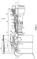
FIG. 1 illustrates an exemplary gas turbine engine, in accordance with various embodiments; -
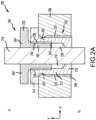
FIG. 2A illustrates an egress seal fitting, in accordance with various embodiments; -
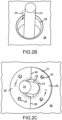
FIG. 2B illustrates a penetration for an egress seal fitting, in accordance with various embodiments; -
FIG. 2C illustrates a housing of an egress seal fitting, in accordance with various embodiments; -
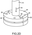
FIG. 2D illustrates an egress seal fitting, in accordance with various embodiments; -
FIG. 3A illustrates an egress seal fitting, in accordance with various embodiments; -
FIG. 3B illustrates an egress seal fitting, in accordance with various embodiments; -
FIG. 3C illustrates an egress seal fitting, in accordance with various embodiments; -
FIG. 3D illustrates an egress seal fitting, in accordance with various embodiments; -
FIG. 3E illustrates an egress seal fitting, in accordance with various embodiments; -
FIG. 4 illustrates a housing for an egress seal fitting, in accordance with various embodiments; and -
FIG. 5 illustrates a method of manufacturing a CMC structure, in accordance with various embodiments. - The detailed description of exemplary embodiments herein makes reference to the accompanying drawings, which show exemplary embodiments by way of illustration and their best mode. While these exemplary embodiments are described in sufficient detail to enable those skilled in the art to practice the disclosures, it should be understood that other embodiments may be realized and that logical, chemical, and mechanical changes may be made without departing from the scope of the disclosures. Thus, the detailed description herein is presented for purposes of illustration only and not of limitation. For example, the steps recited in any of the method or process descriptions may be executed in any order and are not necessarily limited to the order presented. Furthermore, any reference to singular includes plural embodiments, and any reference to more than one component or step may include a singular embodiment or step. Also, any reference to attached, fixed, connected or the like may include permanent, removable, temporary, partial, full and/or any other possible attachment option. Additionally, any reference to without contact (or similar phrases) may also include reduced contact or minimal contact.
- In various embodiments and with reference to
FIG. 1 , agas turbine engine 20 is provided.Gas turbine engine 20 may be a two-spool turbofan that generally incorporates afan section 22, acompressor section 24, acombustor section 26 and aturbine section 28. In operation,fan section 22 can drive air along a bypass flow-path B whilecompressor section 24 can drive air for compression and communication intocombustor section 26 then expansion throughturbine section 28. Although depicted as a turbofangas turbine engine 20 herein, it should be understood that the concepts described herein are not limited to use with turbofans as the teachings may be applied to other types of turbine engines including turbojet engines, a low-bypass turbofans, a high bypass turbofans, or any other gas turbine known to those skilled in the art. -
Gas turbine engine 20 may generally comprise alow speed spool 30 and ahigh speed spool 32 mounted for rotation about an engine central longitudinal axis A-A' relative to an enginestatic structure 36 via one or more bearing systems 38 (shown as bearing system 38-1 and bearing system 38-2). It should be understood thatvarious bearing systems 38 at various locations may alternatively or additionally be provided, including for example,bearing system 38, bearing system 38-1, and bearing system 38-2. -
Low speed spool 30 may generally comprise aninner shaft 40 that interconnects afan 42, a low pressure (or first) compressor section 44 (also referred to a low pressure compressor) and a low pressure (or first)turbine section 46.Inner shaft 40 may be connected tofan 42 through a gearedarchitecture 48 that can drivefan 42 at a lower speed thanlow speed spool 30. Gearedarchitecture 48 may comprise agear assembly 60 enclosed within agear housing 62.Gear assembly 60 couplesinner shaft 40 to a rotating fan structure.High speed spool 32 may comprise anouter shaft 50 that interconnects a high pressure compressor ("HPC") 52 (e.g., a second compressor section) and high pressure (or second)turbine section 54. Acombustor 56 may be located betweenHPC 52 andhigh pressure turbine 54. Amid-turbine frame 57 of enginestatic structure 36 may be located generally betweenhigh pressure turbine 54 andlow pressure turbine 46.Mid-turbine frame 57 may support one ormore bearing systems 38 inturbine section 28.Inner shaft 40 andouter shaft 50 may be concentric and rotate via bearingsystems 38 about the engine central longitudinal axis A-A', which is collinear with their longitudinal axes. As used herein, a "high pressure" compressor or turbine experiences a higher pressure than a corresponding "low pressure" compressor or turbine. - The core airflow C may be compressed by
low pressure compressor 44 thenHPC 52, mixed and burned with fuel incombustor 56, then expanded overhigh pressure turbine 54 andlow pressure turbine 46.Mid-turbine frame 57 includesairfoils 59 which are in the core airflow path.Low pressure turbine 46, andhigh pressure turbine 54 rotationally drive the respectivelow speed spool 30 andhigh speed spool 32 in response to the expansion. -
Gas turbine engine 20 may be, for example, a high-bypass geared aircraft engine. In various embodiments, the bypass ratio ofgas turbine engine 20 may be greater than about six (6). In various embodiments, the bypass ratio ofgas turbine engine 20 may be greater than ten (10). In various embodiments, gearedarchitecture 48 may be an epicyclic gear train, such as a star gear system (sun gear in meshing engagement with a plurality of star gears supported by a carrier and in meshing engagement with a ring gear) or other gear system.Geared architecture 48 may have a gear reduction ratio of greater than about 2.3 andlow pressure turbine 46 may have a pressure ratio that is greater than about 5. In various embodiments, the bypass ratio ofgas turbine engine 20 is greater than about ten (10:1). In various embodiments, the diameter offan 42 may be significantly larger than that of thelow pressure compressor 44, and thelow pressure turbine 46 may have a pressure ratio that is greater than about (5:1).Low pressure turbine 46 pressure ratio may be measured prior to inlet oflow pressure turbine 46 as related to the pressure at the outlet oflow pressure turbine 46 prior to an exhaust nozzle. It should be understood, however, that the above parameters are exemplary of various embodiments of a suitable geared architecture engine and that the present disclosure contemplates other gas turbine engines including direct drive turbofans. - In various embodiments, the next generation of turbofan engines may be designed for higher efficiency which is associated with higher pressure ratios and higher temperatures in the
HPC 52. These higher operating temperatures and pressure ratios may create operating environments that may cause thermal loads that are higher than the thermal loads encountered in conventional turbofan engines, which may shorten the operational life of current components. - In various embodiments,
HPC 52 may comprise alternating rows of rotating rotors and stationary stators. Stators may have a cantilevered configuration or a shrouded configuration. More specifically, a stator may comprise a stator vane, a casing support and a hub support. In this regard, a stator vane may be supported along an outer diameter by a casing support and along an inner diameter by a hub support. In contrast, a cantilevered stator may comprise a stator vane that is only retained and/or supported at the casing (e.g., along an outer diameter). - In various embodiments, rotors may be configured to compress and spin a fluid flow. Stators may be configured to receive and straighten the fluid flow. In operation, the fluid flow discharged from the trailing edge of stators may be straightened (e.g., the flow may be directed in a substantially parallel path to the centerline of the engine and/or HPC) to increase and/or improve the efficiency of the engine and, more specifically, to achieve maximum and/or near maximum compression and efficiency when the straightened air is compressed and spun by rotor 64.
- According to various embodiments and with reference to
FIGS. 1 and2A , an egress seal fitting 200 is shown in cross section through the XY-plane. Seal fitting 200 comprises ahousing 202 and adriver 204.Housing 202 is coupled to abulkhead 206, such as theHPC 52 case, atpenetration 208. In various embodiments,bulkhead 206 divides a low pressure compartment at a first pressure P1 from a relatively high pressure compartment at a second pressure P2. In various embodiments, the pressure differential between P1 and P2 may be about 10,000 psi [69 Mpa] where about in this context means ± 10%. A penetrating member such ascable 210 or other penetrating member (e.g., a pipe, duct, optical fiber, etc.) penetrates the bulkhead atpenetration 208. In various embodiments, thehousing 202 may comprise an annularcylindrical structure 212 extending between aflanged portion 214 and abase portion 216. Thedriver 204 is coupled about thecable 210 and disposed within thehousing 202 thereby defining acavity 218 within thehousing 202 proximate thebase portion 216. - With additional references to
FIGs. 2B, 2C and2D , thehousing 202 is separated into a first housing half 202'and asecond housing half 202".Cable 210 is passed throughpenetration 208 of bulkhead 206 (arrow 210'). The first housing half 202' and thesecond housing half 202" are inserted about thecable 210 into thepenetration 208 and coupled to thebulkhead 206. In various embodiments, thepenetration 208 may be threaded and thehousing 202 may include corresponding threads. The first housing half 202' may be coupled to thebulkhead 206 by a first external threadedsurface 220. In like regard, thesecond housing half 202" may be coupled to the bulkhead by a second external threadedsurface 222.Flanged portion 214 may includetool interfaces 224 configured to enable thehousing 202 to receive torque from a torque tool such as, for example, a spanner wrench. In various embodiments, torque FT may be applied at the tool interfaces 224 and thehousing separation plane 226 may be configured to balance and/or distribute the torque between the halves (202', 202") and, in this regard, thehousing 202 may behave as a monolithic structure. For example,housing 202 may be formed as a monolithic structure including a kerf portion at thehousing separation plane 226 thereby tending to impart a relatively oblate geometry to thehousing 202. In response to separatinghousing 202 into the halves (202', 202"), the kerf portion may be removed, tending thereby to impart a circular geometry to thehousing 202 conducive to distributing the torque force FT. - In various embodiments, a
seal member 228 is inserted into thecavity 218 and disposed about thecable 210. The seal member may comprise one of a potting material (e.g, a room temperature vulcanization compound, a clay, an epoxy, etc.), an O-ring, a ferrule, and/or the like. In various embodiments, thedriver 204 comprises an annularcylindrical drive portion 230 coupled to ahead 232. The drive portion may comprise an externally threadedsurface 234 extending along the external diameter of the drive portion. The externally threadedsurface 234 may be configured to engage with respective first internally threadedsurface 236 and second internally threadedsurface 238 of the housing halves (202', 202"). In various embodiments, each of the first internally threadedsurface 236 and second internally threadedsurface 238 may extend only partially over the inner diameter of the annularcylindrical structure 212 to define adriver stop 240. - In similar fashion to
housing 202, thedriver 204 is divided into a first driver half 204' and asecond driver half 204". The first driver half 204' and thesecond driver half 204" are inserted about thecable 210 into thehousing 202.Head 232 may include the tool interfaces 224' configured to enable thedriver 204 to receive torque from a torque tool such as, for example, a spanner wrench. In various embodiments, second torque FT2 may be applied at the tool interfaces 224' and thedriver separation plane 242 may be configured to balance and/or distribute the torque between the halves (204', 204") and, in this regard, thedriver 204 may behave as a monolithic structure. For example,driver 204 may be formed as a monolithic structure including a kerf portion at thedriver separation plane 242 thereby tending to impart a relatively oblate geometry to thedriver 204. In response to separatingdriver 204 into the halves (204', 204"), the kerf portion may be removed tending thereby to impart a circular geometry to thedriver 204 conducive to distributing the second torque force FT2. In response to the second torque force FT2 thedriver 204 may apply axial (along arrow 244) pressure to theseal member 228 tending to cause theseal member 228 to expand radially between the housing and thecable 210. In this regard, the expansion of theseal member 228 in response to the axial pressure generated by thedriver 204 tends to effect a pressure seal between thecable 210 and thehousing 202. In various embodiments,driver 204 may contact thedriver stop 240 in response to the second torque force FT2 and, in this regard, the pressure applied by thedriver 204 to theseal member 228 may be limited to a desired pressure. - In various embodiments and with additional reference to
FIGs. 3A through 3E , an egress seal fitting 300 is shown in various stages of assembly. Egress seal fitting 300 comprises features, geometries, construction, materials, manufacturing techniques, and/or internal components similar to egress seal fitting 300 but having a hexagonal head and flanged portion.FIG. 3A illustrates a housing half 302' disposed about acable 310 prior to insertion at apenetration 308.FIG. 3B illustrates thehousing 302 about thecable 310 and coupled to thebulkhead 306 at thepenetration 308.FIG. 3C illustrates theseal member 328 disposed about thecable 310 prior to insertion into thecavity 318 of thehousing 302.FIG. 3D illustrates a driver half 304' disposed about thecable 310 prior to insertion within thehousing 302.FIG. 3E illustrates thedriver 304 torqued and coupled to thehousing 302 to generate a seal about thecable 310. - In various embodiments and with additional reference to
FIG. 4 , ahousing 400 for an egress seal fitting is illustrated.Housing 400 comprises features, geometries, construction, materials, manufacturing techniques, and/or internal components similar tohousing 202.Housing 400 differs in comprising anelongate base portion 402. Theelongate base portion 402 may comprise a plurality of driver cavities such asfirst driver cavity 404 and second driver cavity 404'. Each of the driver cavities may be configured to receive a cable and couple with a driver such as, for example,driver 204 ordriver 304. - With additional reference to
FIG. 5 , amethod 500 of sealing a pressure bulkhead penetration may comprise disposing a housing about a penetrating member passing through the pressure bulkhead penetration (step 502).Method 500 includes coupling the housing to the pressure bulkhead penetration and disposing a seal member within a cavity of the housing (step 504).Method 500 includes disposing a driver about the penetrating member and coupling the driver to the housing (step 506).Method 500 includes applying a pressure to the seal member via the driver and expanding the seal member radially between the housing and the penetrating member in response to the pressure (step 508). - Benefits, other advantages, and solutions to problems have been described herein with regard to specific embodiments. Furthermore, the connecting lines shown in the various figures contained herein are intended to represent exemplary functional relationships and/or physical couplings between the various elements. It should be noted that many alternative or additional functional relationships or physical connections may be present in a practical system. However, the benefits, advantages, solutions to problems, and any elements that may cause any benefit, advantage, or solution to occur or become more pronounced are not to be construed as critical, required, or essential features or elements of the disclosures.
- The scope of the disclosures is accordingly to be limited by nothing other than the appended claims, in which reference to an element in the singular is not intended to mean "one and only one" unless explicitly so stated, but rather "one or more." Moreover, where a phrase similar to "at least one of A, B, or C" is used in the claims, it is intended that the phrase be interpreted to mean that A alone may be present in an embodiment, B alone may be present in an embodiment, C alone may be present in an embodiment, or that any combination of the elements A, Band C may be present in a single embodiment; for example, A and B, A and C, B and C, or A and B and C. Different cross-hatching is used throughout the figures to denote different parts but not necessarily to denote the same or different materials.
- Systems, methods and apparatus are provided herein. In the detailed description herein, references to "one embodiment", "an embodiment", "an example embodiment", etc., indicate that the embodiment described may include a particular feature, structure, or characteristic, but every embodiment may not necessarily include the particular feature, structure, or characteristic. Moreover, such phrases are not necessarily referring to the same embodiment. Further, when a particular feature, structure, or characteristic is described in connection with an embodiment, it is submitted that it is within the knowledge of one skilled in the art to affect such feature, structure, or characteristic in connection with other embodiments whether or not explicitly described. After reading the description, it will be apparent to one skilled in the relevant art(s) how to implement the disclosure in alternative embodiment
- Furthermore, no element, component, or method step in the present disclosure is intended to be dedicated to the public regardless of whether the element, component, or method step is explicitly recited in the claims. As used herein, the terms "comprises", "comprising", or any other variation thereof, are intended to cover a non-exclusive inclusion, such that a process, method, article, or apparatus that comprises a list of elements does not include only those elements but may include other elements not expressly listed or inherent to such process, method, article, or apparatus.
Claims (8)
- An egress seal fitting (200; 300) for a bulkhead penetration (208; 308), comprising:a housing (202; 302; 400), wherein the housing (202; 302; 400) comprises an annular cylindrical structure (212) extending between a flanged portion (214) and a base portion (216; 402) ;a driver (204; 304) configured to couple to the housing (202; 302; 400), wherein the driver (204; 304) comprises an annular cylindrical drive portion (230) and a head (232), wherein the driver (204; 304) is configured to_define a driver cavity (218; 318) within the housing (202; 302; 400); anda seal member (228; 328) configured to be disposed within the driver cavity (218; 318) of the housing (202; 302; 400), wherein the driver (204; 304) is configured to pass a penetrating member (210; 310) through the housing (202; 302; 400) and apply pressure to the seal member (228; 328),characterised in that the housing (202; 302; 400) is separated into a first housing half (202'; 302') and a second housing half (202"),wherein the driver (204; 304) is divided into a first driver half (204'; 304') and a second driver half (204").
- The egress seal fitting (200; 300) of claim 1, wherein the driver (204; 304) is configured to apply an axial pressure to the seal member (228; 328) and expand the seal member (228; 328) radially between the housing (202; 302; 400) and the penetrating member (210; 310).
- A gas turbine engine (20), comprising:a compressor section (24) configured to compress a gas;a combustor section (26) aft of the compressor section (24) and configured to combust the gas;a turbine section (28) aft of the combustor section and configured to extract work from the gas;a pressure bulkhead (206; 306) dividing a first pressure compartment from a second pressure compartment, wherein a pressure differential exists between the first pressure compartment and the second pressure compartment; andan egress seal fitting (200; 300) as claimed in claim 1 and coupled to a penetration of the pressure bulkhead (206; 306),wherein the driver (204; 304) is coupled to the housing (202; 302; 400) and defines a cavity within the housing (202; 302; 400), andthe seal member (228; 328) is disposed within the cavity of the housing (202; 302; 400) and compressed by the driver (204; 304),wherein the driver (204; 304) is configured to pass a penetrating member (210; 310) through the housing (202; 302; 400) and expand the seal member (228; 328) radially between the housing (202; 302; 400) and the penetrating member (210; 310).
- The egress seal fitting (200; 300) of claim 1 or 2 or the gas turbine engine (20) of claim 3, wherein each of the first housing half (202'; 302') and the second housing half (202") comprise a corresponding externally threaded surface (220, 222) and a corresponding internally threaded surface (236, 238).
- The egress seal fitting (200; 300) or the gas turbine engine (20) of claim 4, wherein the internally threaded surface (236, 238).of the first housing half (202'; 302') and the internally threaded surface (236, 238).of the second housing half (202") each extend only partially over an internal diameter of the annular cylindrical structure (212) to define a driver stop (240).
- The egress seal fitting (200; 300) of any of claims 1, 2, 4 or 5 or the gas turbine engine (20) of any of claims 3 to 5, wherein the drive portion comprises an externally threaded surface (234).
- The egress seal fitting (200; 300) of any of claims 1, 2 or 4 to 6, or the gas turbine engine (20) of any of claims 3 to 6, wherein the housing (400) comprises an elongate base portion (402) including a first driver cavity (404) and a second driver cavity (404').
- A method of sealing a pressure bulkhead penetration, the method comprising:disposing a housing (202; 302; 400) about a penetrating member (210; 310) passing through the bulkhead penetration (208; 308);coupling the housing (202; 302; 400) to the pressure bulkhead penetration;disposing a seal member (228; 328) within a cavity of the housing,(202; 302; 400);disposing a driver (204; 304) about the penetrating member (210; 310) and coupling the driver (204; 304) to the housing (202; 302; 400); andapplying a pressure to the seal member (228; 328) via the driver (204; 304) and expanding the seal member (228; 328) radially between the housing (202; 302; 400) and the penetrating member (210; 310) in response to the pressure,wherein the housing (202; 302; 400) comprises an annular cylindrical structure (212) extending between a flanged portion (214) and a base portion (216; 402),wherein the driver (204; 304) comprises an annular cylindrical drive portion (230) and a head (232),wherein the driver (204; 304) is configured to define a driver cavity (218; 318) within the housing (202; 302; 400),characterised in that the housing (202; 302; 400) is separated into a first housing half (202'; 302') and a second housing half (202"),wherein the driver (204; 304) is divided into a first driver half (204'; 304') and a second driver half (204").
Applications Claiming Priority (1)
| Application Number | Priority Date | Filing Date | Title |
|---|---|---|---|
| US16/365,388 US11070041B2 (en) | 2019-03-26 | 2019-03-26 | Egress seal fitting |
Publications (2)
| Publication Number | Publication Date |
|---|---|
| EP3722558A1 EP3722558A1 (en) | 2020-10-14 |
| EP3722558B1 true EP3722558B1 (en) | 2023-04-26 |
Family
ID=69844603
Family Applications (1)
| Application Number | Title | Priority Date | Filing Date |
|---|---|---|---|
| EP20163186.8A Active EP3722558B1 (en) | 2019-03-26 | 2020-03-13 | Egress seal fitting |
Country Status (2)
| Country | Link |
|---|---|
| US (1) | US11070041B2 (en) |
| EP (1) | EP3722558B1 (en) |
Families Citing this family (2)
| Publication number | Priority date | Publication date | Assignee | Title |
|---|---|---|---|---|
| US11926008B2 (en) | 2021-12-27 | 2024-03-12 | Pratt & Whitney Canada Corp. | Tools and methods for assembling a seal device of a gas turbine engine |
| US12345168B2 (en) * | 2023-11-27 | 2025-07-01 | Rtx Corporation | Fitting for an instrument lead with a connector for a gas turbine engine |
Family Cites Families (14)
| Publication number | Priority date | Publication date | Assignee | Title |
|---|---|---|---|---|
| CH202926A (en) | 1937-10-05 | 1939-02-15 | Leblond Andre | Watertight seal applicable in particular through a wall. |
| US2365785A (en) | 1942-04-16 | 1944-12-26 | Tinnerman Products Inc | Fastening device |
| US2431154A (en) * | 1946-03-28 | 1947-11-18 | Bay Shore Machine Company Inc | Cable securing device |
| BE518103A (en) * | 1953-03-09 | |||
| US2813692A (en) | 1954-05-28 | 1957-11-19 | Boeing Co | Sealed bulkhead installations of electric wires |
| US3076655A (en) | 1958-07-21 | 1963-02-05 | Lockheed Aircraft Corp | Split seal |
| US3224796A (en) | 1962-08-10 | 1965-12-21 | Harold H Burkitt | Wall bushing for pipes and cables |
| US3734547A (en) * | 1971-09-09 | 1973-05-22 | N Kojima | Clamping device by segmental thread pipe for joint |
| FR2567230B1 (en) | 1984-07-04 | 1989-01-27 | Capri Codec Sa | FIRE PROTECTION |
| FR2567239B1 (en) | 1984-07-04 | 1989-01-13 | Capri Codec Sa | METHOD AND CABLE GLAND FOR SEALING AND FIXING AN OPTICAL FIBER CABLE THROUGH A WALL |
| US5305609A (en) | 1993-05-14 | 1994-04-26 | United Technologies Corporation | Seal assembly |
| JP2002155703A (en) | 2000-11-21 | 2002-05-31 | Mitsubishi Heavy Ind Ltd | Sealing structure for stream passage between stationary blade and blade ring of gas turbine |
| ITGE20080004A1 (en) * | 2008-01-16 | 2009-07-17 | Ultraflex Spa | GUIDE TO DRIVE A WALL OF PIPES, CABLES OR THE LIKE. |
| US20140178185A1 (en) * | 2012-12-21 | 2014-06-26 | United Technologies Corporation | Egress seal assembly |
-
2019
- 2019-03-26 US US16/365,388 patent/US11070041B2/en active Active
-
2020
- 2020-03-13 EP EP20163186.8A patent/EP3722558B1/en active Active
Also Published As
| Publication number | Publication date |
|---|---|
| US11070041B2 (en) | 2021-07-20 |
| EP3722558A1 (en) | 2020-10-14 |
| US20200313416A1 (en) | 2020-10-01 |
Similar Documents
| Publication | Publication Date | Title |
|---|---|---|
| US10533446B2 (en) | Alternative W-seal groove arrangement | |
| EP3683405A1 (en) | Frustic load transmission feature for composite structures | |
| EP2900956B1 (en) | Gas turbine engine comprising a seal assembly for a static structure thereof | |
| EP3670860A1 (en) | Fan and low pressure compressor geared to a low speed spool of a gas turbine engine | |
| EP3246517B1 (en) | Fastener openings for stress distribution | |
| EP3722558A1 (en) | Egress seal fitting | |
| EP3546700A1 (en) | Double bore basket | |
| US20200182060A1 (en) | Dual cooling airflow to blades | |
| EP3730828A1 (en) | Dynamic sleeve seal fittings | |
| EP3748134B1 (en) | Vane airfoil shapes for embedded members | |
| US11326617B2 (en) | Boost compressor assembly | |
| EP3081748B1 (en) | Gas turbine engine system comprising a seal ring | |
| US10767867B2 (en) | Bearing support assembly | |
| EP3770476B1 (en) | Compliant jumper tube fitting | |
| US11408300B2 (en) | Rotor overspeed protection assembly | |
| EP3623578A1 (en) | Gas turbine blade with dirt removal holes | |
| EP3470685A1 (en) | Gap closing wearliner | |
| US20150354385A1 (en) | Flapper seal apparatus and system | |
| EP2930304B1 (en) | High pressure compressor thermal shield apparatus and system |
Legal Events
| Date | Code | Title | Description |
|---|---|---|---|
| PUAI | Public reference made under article 153(3) epc to a published international application that has entered the european phase |
Free format text: ORIGINAL CODE: 0009012 |
|
| STAA | Information on the status of an ep patent application or granted ep patent |
Free format text: STATUS: THE APPLICATION HAS BEEN PUBLISHED |
|
| AK | Designated contracting states |
Kind code of ref document: A1 Designated state(s): AL AT BE BG CH CY CZ DE DK EE ES FI FR GB GR HR HU IE IS IT LI LT LU LV MC MK MT NL NO PL PT RO RS SE SI SK SM TR |
|
| AX | Request for extension of the european patent |
Extension state: BA ME |
|
| RAP1 | Party data changed (applicant data changed or rights of an application transferred) |
Owner name: RAYTHEON TECHNOLOGIES CORPORATION |
|
| STAA | Information on the status of an ep patent application or granted ep patent |
Free format text: STATUS: REQUEST FOR EXAMINATION WAS MADE |
|
| 17P | Request for examination filed |
Effective date: 20210414 |
|
| RBV | Designated contracting states (corrected) |
Designated state(s): AL AT BE BG CH CY CZ DE DK EE ES FI FR GB GR HR HU IE IS IT LI LT LU LV MC MK MT NL NO PL PT RO RS SE SI SK SM TR |
|
| GRAP | Despatch of communication of intention to grant a patent |
Free format text: ORIGINAL CODE: EPIDOSNIGR1 |
|
| STAA | Information on the status of an ep patent application or granted ep patent |
Free format text: STATUS: GRANT OF PATENT IS INTENDED |
|
| INTG | Intention to grant announced |
Effective date: 20221020 |
|
| GRAS | Grant fee paid |
Free format text: ORIGINAL CODE: EPIDOSNIGR3 |
|
| GRAA | (expected) grant |
Free format text: ORIGINAL CODE: 0009210 |
|
| STAA | Information on the status of an ep patent application or granted ep patent |
Free format text: STATUS: THE PATENT HAS BEEN GRANTED |
|
| AK | Designated contracting states |
Kind code of ref document: B1 Designated state(s): AL AT BE BG CH CY CZ DE DK EE ES FI FR GB GR HR HU IE IS IT LI LT LU LV MC MK MT NL NO PL PT RO RS SE SI SK SM TR |
|
| REG | Reference to a national code |
Ref country code: GB Ref legal event code: FG4D |
|
| REG | Reference to a national code |
Ref country code: CH Ref legal event code: EP |
|
| REG | Reference to a national code |
Ref country code: DE Ref legal event code: R096 Ref document number: 602020010022 Country of ref document: DE |
|
| REG | Reference to a national code |
Ref country code: AT Ref legal event code: REF Ref document number: 1562952 Country of ref document: AT Kind code of ref document: T Effective date: 20230515 |
|
| REG | Reference to a national code |
Ref country code: IE Ref legal event code: FG4D |
|
| P01 | Opt-out of the competence of the unified patent court (upc) registered |
Effective date: 20230603 |
|
| REG | Reference to a national code |
Ref country code: LT Ref legal event code: MG9D |
|
| REG | Reference to a national code |
Ref country code: NL Ref legal event code: MP Effective date: 20230426 |
|
| REG | Reference to a national code |
Ref country code: AT Ref legal event code: MK05 Ref document number: 1562952 Country of ref document: AT Kind code of ref document: T Effective date: 20230426 |
|
| PG25 | Lapsed in a contracting state [announced via postgrant information from national office to epo] |
Ref country code: NL Free format text: LAPSE BECAUSE OF FAILURE TO SUBMIT A TRANSLATION OF THE DESCRIPTION OR TO PAY THE FEE WITHIN THE PRESCRIBED TIME-LIMIT Effective date: 20230426 |
|
| PG25 | Lapsed in a contracting state [announced via postgrant information from national office to epo] |
Ref country code: SE Free format text: LAPSE BECAUSE OF FAILURE TO SUBMIT A TRANSLATION OF THE DESCRIPTION OR TO PAY THE FEE WITHIN THE PRESCRIBED TIME-LIMIT Effective date: 20230426 Ref country code: PT Free format text: LAPSE BECAUSE OF FAILURE TO SUBMIT A TRANSLATION OF THE DESCRIPTION OR TO PAY THE FEE WITHIN THE PRESCRIBED TIME-LIMIT Effective date: 20230828 Ref country code: NO Free format text: LAPSE BECAUSE OF FAILURE TO SUBMIT A TRANSLATION OF THE DESCRIPTION OR TO PAY THE FEE WITHIN THE PRESCRIBED TIME-LIMIT Effective date: 20230726 Ref country code: ES Free format text: LAPSE BECAUSE OF FAILURE TO SUBMIT A TRANSLATION OF THE DESCRIPTION OR TO PAY THE FEE WITHIN THE PRESCRIBED TIME-LIMIT Effective date: 20230426 Ref country code: AT Free format text: LAPSE BECAUSE OF FAILURE TO SUBMIT A TRANSLATION OF THE DESCRIPTION OR TO PAY THE FEE WITHIN THE PRESCRIBED TIME-LIMIT Effective date: 20230426 |
|
| RAP4 | Party data changed (patent owner data changed or rights of a patent transferred) |
Owner name: RTX CORPORATION |
|
| PG25 | Lapsed in a contracting state [announced via postgrant information from national office to epo] |
Ref country code: RS Free format text: LAPSE BECAUSE OF FAILURE TO SUBMIT A TRANSLATION OF THE DESCRIPTION OR TO PAY THE FEE WITHIN THE PRESCRIBED TIME-LIMIT Effective date: 20230426 Ref country code: PL Free format text: LAPSE BECAUSE OF FAILURE TO SUBMIT A TRANSLATION OF THE DESCRIPTION OR TO PAY THE FEE WITHIN THE PRESCRIBED TIME-LIMIT Effective date: 20230426 Ref country code: LV Free format text: LAPSE BECAUSE OF FAILURE TO SUBMIT A TRANSLATION OF THE DESCRIPTION OR TO PAY THE FEE WITHIN THE PRESCRIBED TIME-LIMIT Effective date: 20230426 Ref country code: LT Free format text: LAPSE BECAUSE OF FAILURE TO SUBMIT A TRANSLATION OF THE DESCRIPTION OR TO PAY THE FEE WITHIN THE PRESCRIBED TIME-LIMIT Effective date: 20230426 Ref country code: IS Free format text: LAPSE BECAUSE OF FAILURE TO SUBMIT A TRANSLATION OF THE DESCRIPTION OR TO PAY THE FEE WITHIN THE PRESCRIBED TIME-LIMIT Effective date: 20230826 Ref country code: HR Free format text: LAPSE BECAUSE OF FAILURE TO SUBMIT A TRANSLATION OF THE DESCRIPTION OR TO PAY THE FEE WITHIN THE PRESCRIBED TIME-LIMIT Effective date: 20230426 Ref country code: GR Free format text: LAPSE BECAUSE OF FAILURE TO SUBMIT A TRANSLATION OF THE DESCRIPTION OR TO PAY THE FEE WITHIN THE PRESCRIBED TIME-LIMIT Effective date: 20230727 |
|
| PG25 | Lapsed in a contracting state [announced via postgrant information from national office to epo] |
Ref country code: FI Free format text: LAPSE BECAUSE OF FAILURE TO SUBMIT A TRANSLATION OF THE DESCRIPTION OR TO PAY THE FEE WITHIN THE PRESCRIBED TIME-LIMIT Effective date: 20230426 |
|
| PG25 | Lapsed in a contracting state [announced via postgrant information from national office to epo] |
Ref country code: SK Free format text: LAPSE BECAUSE OF FAILURE TO SUBMIT A TRANSLATION OF THE DESCRIPTION OR TO PAY THE FEE WITHIN THE PRESCRIBED TIME-LIMIT Effective date: 20230426 |
|
| REG | Reference to a national code |
Ref country code: DE Ref legal event code: R097 Ref document number: 602020010022 Country of ref document: DE |
|
| PG25 | Lapsed in a contracting state [announced via postgrant information from national office to epo] |
Ref country code: SM Free format text: LAPSE BECAUSE OF FAILURE TO SUBMIT A TRANSLATION OF THE DESCRIPTION OR TO PAY THE FEE WITHIN THE PRESCRIBED TIME-LIMIT Effective date: 20230426 Ref country code: SK Free format text: LAPSE BECAUSE OF FAILURE TO SUBMIT A TRANSLATION OF THE DESCRIPTION OR TO PAY THE FEE WITHIN THE PRESCRIBED TIME-LIMIT Effective date: 20230426 Ref country code: RO Free format text: LAPSE BECAUSE OF FAILURE TO SUBMIT A TRANSLATION OF THE DESCRIPTION OR TO PAY THE FEE WITHIN THE PRESCRIBED TIME-LIMIT Effective date: 20230426 Ref country code: EE Free format text: LAPSE BECAUSE OF FAILURE TO SUBMIT A TRANSLATION OF THE DESCRIPTION OR TO PAY THE FEE WITHIN THE PRESCRIBED TIME-LIMIT Effective date: 20230426 Ref country code: DK Free format text: LAPSE BECAUSE OF FAILURE TO SUBMIT A TRANSLATION OF THE DESCRIPTION OR TO PAY THE FEE WITHIN THE PRESCRIBED TIME-LIMIT Effective date: 20230426 Ref country code: CZ Free format text: LAPSE BECAUSE OF FAILURE TO SUBMIT A TRANSLATION OF THE DESCRIPTION OR TO PAY THE FEE WITHIN THE PRESCRIBED TIME-LIMIT Effective date: 20230426 |
|
| PLBE | No opposition filed within time limit |
Free format text: ORIGINAL CODE: 0009261 |
|
| STAA | Information on the status of an ep patent application or granted ep patent |
Free format text: STATUS: NO OPPOSITION FILED WITHIN TIME LIMIT |
|
| 26N | No opposition filed |
Effective date: 20240129 |
|
| PG25 | Lapsed in a contracting state [announced via postgrant information from national office to epo] |
Ref country code: SI Free format text: LAPSE BECAUSE OF FAILURE TO SUBMIT A TRANSLATION OF THE DESCRIPTION OR TO PAY THE FEE WITHIN THE PRESCRIBED TIME-LIMIT Effective date: 20230426 |
|
| PG25 | Lapsed in a contracting state [announced via postgrant information from national office to epo] |
Ref country code: SI Free format text: LAPSE BECAUSE OF FAILURE TO SUBMIT A TRANSLATION OF THE DESCRIPTION OR TO PAY THE FEE WITHIN THE PRESCRIBED TIME-LIMIT Effective date: 20230426 Ref country code: IT Free format text: LAPSE BECAUSE OF FAILURE TO SUBMIT A TRANSLATION OF THE DESCRIPTION OR TO PAY THE FEE WITHIN THE PRESCRIBED TIME-LIMIT Effective date: 20230426 |
|
| REG | Reference to a national code |
Ref country code: CH Ref legal event code: PL |
|
| PG25 | Lapsed in a contracting state [announced via postgrant information from national office to epo] |
Ref country code: BG Free format text: LAPSE BECAUSE OF FAILURE TO SUBMIT A TRANSLATION OF THE DESCRIPTION OR TO PAY THE FEE WITHIN THE PRESCRIBED TIME-LIMIT Effective date: 20230426 |
|
| PG25 | Lapsed in a contracting state [announced via postgrant information from national office to epo] |
Ref country code: LU Free format text: LAPSE BECAUSE OF NON-PAYMENT OF DUE FEES Effective date: 20240313 |
|
| PG25 | Lapsed in a contracting state [announced via postgrant information from national office to epo] |
Ref country code: MC Free format text: LAPSE BECAUSE OF FAILURE TO SUBMIT A TRANSLATION OF THE DESCRIPTION OR TO PAY THE FEE WITHIN THE PRESCRIBED TIME-LIMIT Effective date: 20230426 |
|
| PG25 | Lapsed in a contracting state [announced via postgrant information from national office to epo] |
Ref country code: MC Free format text: LAPSE BECAUSE OF FAILURE TO SUBMIT A TRANSLATION OF THE DESCRIPTION OR TO PAY THE FEE WITHIN THE PRESCRIBED TIME-LIMIT Effective date: 20230426 Ref country code: LU Free format text: LAPSE BECAUSE OF NON-PAYMENT OF DUE FEES Effective date: 20240313 Ref country code: BG Free format text: LAPSE BECAUSE OF FAILURE TO SUBMIT A TRANSLATION OF THE DESCRIPTION OR TO PAY THE FEE WITHIN THE PRESCRIBED TIME-LIMIT Effective date: 20230426 |
|
| REG | Reference to a national code |
Ref country code: BE Ref legal event code: MM Effective date: 20240331 |
|
| PG25 | Lapsed in a contracting state [announced via postgrant information from national office to epo] |
Ref country code: BE Free format text: LAPSE BECAUSE OF NON-PAYMENT OF DUE FEES Effective date: 20240331 |
|
| PG25 | Lapsed in a contracting state [announced via postgrant information from national office to epo] |
Ref country code: IE Free format text: LAPSE BECAUSE OF NON-PAYMENT OF DUE FEES Effective date: 20240313 |
|
| PG25 | Lapsed in a contracting state [announced via postgrant information from national office to epo] |
Ref country code: IE Free format text: LAPSE BECAUSE OF NON-PAYMENT OF DUE FEES Effective date: 20240313 Ref country code: BE Free format text: LAPSE BECAUSE OF NON-PAYMENT OF DUE FEES Effective date: 20240331 Ref country code: CH Free format text: LAPSE BECAUSE OF NON-PAYMENT OF DUE FEES Effective date: 20240331 |
|
| PG25 | Lapsed in a contracting state [announced via postgrant information from national office to epo] |
Ref country code: CY Free format text: LAPSE BECAUSE OF FAILURE TO SUBMIT A TRANSLATION OF THE DESCRIPTION OR TO PAY THE FEE WITHIN THE PRESCRIBED TIME-LIMIT; INVALID AB INITIO Effective date: 20200313 |
|
| PG25 | Lapsed in a contracting state [announced via postgrant information from national office to epo] |
Ref country code: HU Free format text: LAPSE BECAUSE OF FAILURE TO SUBMIT A TRANSLATION OF THE DESCRIPTION OR TO PAY THE FEE WITHIN THE PRESCRIBED TIME-LIMIT; INVALID AB INITIO Effective date: 20200313 |
|
| REG | Reference to a national code |
Ref country code: DE Ref legal event code: R081 Ref document number: 602020010022 Country of ref document: DE Owner name: RTX CORPORATION (N.D.GES.D. STAATES DELAWARE),, US Free format text: FORMER OWNER: RAYTHEON TECHNOLOGIES CORPORATION, FARMINGTON, CT, US |
|
| PG25 | Lapsed in a contracting state [announced via postgrant information from national office to epo] |
Ref country code: TR Free format text: LAPSE BECAUSE OF FAILURE TO SUBMIT A TRANSLATION OF THE DESCRIPTION OR TO PAY THE FEE WITHIN THE PRESCRIBED TIME-LIMIT Effective date: 20230426 |
|
| PGFP | Annual fee paid to national office [announced via postgrant information from national office to epo] |
Ref country code: GB Payment date: 20260220 Year of fee payment: 7 |
|
| PGFP | Annual fee paid to national office [announced via postgrant information from national office to epo] |
Ref country code: DE Payment date: 20260219 Year of fee payment: 7 |
|
| PGFP | Annual fee paid to national office [announced via postgrant information from national office to epo] |
Ref country code: FR Payment date: 20260219 Year of fee payment: 7 |