EP3722211A1 - Dynamic illumination system for runway illumination - Google Patents
Dynamic illumination system for runway illumination Download PDFInfo
- Publication number
- EP3722211A1 EP3722211A1 EP19382266.5A EP19382266A EP3722211A1 EP 3722211 A1 EP3722211 A1 EP 3722211A1 EP 19382266 A EP19382266 A EP 19382266A EP 3722211 A1 EP3722211 A1 EP 3722211A1
- Authority
- EP
- European Patent Office
- Prior art keywords
- runway
- aircraft
- light source
- actual
- illumination
- Prior art date
- Legal status (The legal status is an assumption and is not a legal conclusion. Google has not performed a legal analysis and makes no representation as to the accuracy of the status listed.)
- Withdrawn
Links
- 238000005286 illumination Methods 0.000 title claims abstract description 38
- 239000011159 matrix material Substances 0.000 claims description 3
- 239000013598 vector Substances 0.000 description 10
- 238000000034 method Methods 0.000 description 3
- 230000004907 flux Effects 0.000 description 2
- 230000001133 acceleration Effects 0.000 description 1
- 238000005516 engineering process Methods 0.000 description 1
- 230000007613 environmental effect Effects 0.000 description 1
- 230000010354 integration Effects 0.000 description 1
Images


Classifications
-
- B—PERFORMING OPERATIONS; TRANSPORTING
- B64—AIRCRAFT; AVIATION; COSMONAUTICS
- B64D—EQUIPMENT FOR FITTING IN OR TO AIRCRAFT; FLIGHT SUITS; PARACHUTES; ARRANGEMENT OR MOUNTING OF POWER PLANTS OR PROPULSION TRANSMISSIONS IN AIRCRAFT
- B64D47/00—Equipment not otherwise provided for
- B64D47/02—Arrangements or adaptations of signal or lighting devices
- B64D47/04—Arrangements or adaptations of signal or lighting devices the lighting devices being primarily intended to illuminate the way ahead
-
- F—MECHANICAL ENGINEERING; LIGHTING; HEATING; WEAPONS; BLASTING
- F21—LIGHTING
- F21V—FUNCTIONAL FEATURES OR DETAILS OF LIGHTING DEVICES OR SYSTEMS THEREOF; STRUCTURAL COMBINATIONS OF LIGHTING DEVICES WITH OTHER ARTICLES, NOT OTHERWISE PROVIDED FOR
- F21V14/00—Controlling the distribution of the light emitted by adjustment of elements
- F21V14/02—Controlling the distribution of the light emitted by adjustment of elements by movement of light sources
-
- F—MECHANICAL ENGINEERING; LIGHTING; HEATING; WEAPONS; BLASTING
- F21—LIGHTING
- F21V—FUNCTIONAL FEATURES OR DETAILS OF LIGHTING DEVICES OR SYSTEMS THEREOF; STRUCTURAL COMBINATIONS OF LIGHTING DEVICES WITH OTHER ARTICLES, NOT OTHERWISE PROVIDED FOR
- F21V21/00—Supporting, suspending, or attaching arrangements for lighting devices; Hand grips
- F21V21/14—Adjustable mountings
- F21V21/15—Adjustable mountings specially adapted for power operation, e.g. by remote control
-
- H—ELECTRICITY
- H05—ELECTRIC TECHNIQUES NOT OTHERWISE PROVIDED FOR
- H05B—ELECTRIC HEATING; ELECTRIC LIGHT SOURCES NOT OTHERWISE PROVIDED FOR; CIRCUIT ARRANGEMENTS FOR ELECTRIC LIGHT SOURCES, IN GENERAL
- H05B45/00—Circuit arrangements for operating light-emitting diodes [LED]
- H05B45/10—Controlling the intensity of the light
-
- H—ELECTRICITY
- H05—ELECTRIC TECHNIQUES NOT OTHERWISE PROVIDED FOR
- H05B—ELECTRIC HEATING; ELECTRIC LIGHT SOURCES NOT OTHERWISE PROVIDED FOR; CIRCUIT ARRANGEMENTS FOR ELECTRIC LIGHT SOURCES, IN GENERAL
- H05B45/00—Circuit arrangements for operating light-emitting diodes [LED]
- H05B45/40—Details of LED load circuits
- H05B45/44—Details of LED load circuits with an active control inside an LED matrix
-
- H—ELECTRICITY
- H05—ELECTRIC TECHNIQUES NOT OTHERWISE PROVIDED FOR
- H05B—ELECTRIC HEATING; ELECTRIC LIGHT SOURCES NOT OTHERWISE PROVIDED FOR; CIRCUIT ARRANGEMENTS FOR ELECTRIC LIGHT SOURCES, IN GENERAL
- H05B47/00—Circuit arrangements for operating light sources in general, i.e. where the type of light source is not relevant
-
- H—ELECTRICITY
- H05—ELECTRIC TECHNIQUES NOT OTHERWISE PROVIDED FOR
- H05B—ELECTRIC HEATING; ELECTRIC LIGHT SOURCES NOT OTHERWISE PROVIDED FOR; CIRCUIT ARRANGEMENTS FOR ELECTRIC LIGHT SOURCES, IN GENERAL
- H05B47/00—Circuit arrangements for operating light sources in general, i.e. where the type of light source is not relevant
- H05B47/10—Controlling the light source
-
- H—ELECTRICITY
- H05—ELECTRIC TECHNIQUES NOT OTHERWISE PROVIDED FOR
- H05B—ELECTRIC HEATING; ELECTRIC LIGHT SOURCES NOT OTHERWISE PROVIDED FOR; CIRCUIT ARRANGEMENTS FOR ELECTRIC LIGHT SOURCES, IN GENERAL
- H05B47/00—Circuit arrangements for operating light sources in general, i.e. where the type of light source is not relevant
- H05B47/10—Controlling the light source
- H05B47/105—Controlling the light source in response to determined parameters
-
- B—PERFORMING OPERATIONS; TRANSPORTING
- B64—AIRCRAFT; AVIATION; COSMONAUTICS
- B64D—EQUIPMENT FOR FITTING IN OR TO AIRCRAFT; FLIGHT SUITS; PARACHUTES; ARRANGEMENT OR MOUNTING OF POWER PLANTS OR PROPULSION TRANSMISSIONS IN AIRCRAFT
- B64D2203/00—Aircraft or airfield lights using LEDs
Definitions
- the present invention refers to a dynamic illumination system for runway illumination. More particularly, the invention is relative to an aircraft illumination system for runway illumination for take-off and landing purposes.
- One object of the invention is to provide an architecture for runway illumination that is more efficient and best adapted to all aircraft attitudes considering its velocity vector.
- Another object of the invention is to provide an architecture for runway illumination that improves the illumination performances in any external environmental conditions, also in low visibility scenarios.
- MEMs Micro-Electro-Mechanical Systems
- image recognition Currently, two main solutions exists for the dynamic illumination of a runway, one solution is based in the use of MEMs (Micro-Electro-Mechanical Systems) computation, and another one is based in image recognition.
- the first solution requires MEMs technology embedded within the light to estimate the relative position and attitude of the aircraft to the runway in order to adapt the illumination accordingly, while the second solution consists of embedding a camera in a light, and recognize the runway by image post treatment to orient the light beam accordingly.
- lights to illuminate the runway are usually designed for a specific reference scenario of attitude of the aircraft for take-off and landing phase, and this reference orientation of the light beam is not always the best adapted to the actual attitude of the aircraft (given by its velocity vector); an example is landing with cross wind or landing at higher velocity (different pitch approach than reference scenario).
- the present invention overcomes the above mentioned drawbacks by providing a dynamic illumination system for runway illumination that solves the above identified limitations of the state of the art.
- the present invention refers to a dynamic illumination system that comprises a light source having an addressable light beam direction, and a control unit configured to:
- the invention provides a dynamic illumination system adapted to orient the light beam towards the direction of the runway selected for takeoff or landing considering the aircraft trajectory at any time.
- the invention provides an easier and a more reliable way of orienting the light beam towards the current and correct direction of the runway in comparison with the state of the art solutions.
- the illumination system comprises a light source, and a control unit.
- the light source has an addressable light beam direction ( L ) that being steerable provides a dynamic illumination, sensitive to the actual aircraft attitude information, and the orientation of the runway ( R ) selected for takeoff or landing.
- Figure 1 schematically shows a first scenery in which an aircraft follows a trajectory deviated from the reference -desired- trajectory. Consequently, the light beam direction is also deviated from the reference -desired- direction considering the aircraft trajectory.
- Figure 1a shows the actual aircraft trajectory ( V ), the reference aircraft trajectory ( Vo ) , the actual light beam direction ( L ), and the reference light beam direction ( Lo ), wherein the reference light beam direction ( Lo ) corresponds to the reference aircraft trajectory ( Vo ) in the vertical plane XY.
- horizontal axis ( x ) is collinear with the longitudinal direction of the selected runway ( R ).
- the aircraft following the actual aircraft trajectory ( V ) forms an angle ⁇ with the horizontal axis x
- the reference -desired as per light orientation default design- aircraft trajectory ( Vo ) forms an angle ⁇ 0 with the horizontal axis x
- the actual aircraft trajectory ( V ) is deviated
- the light beam direction ( L ) is corrected to achieve the desired light beam direction ( Lo ) , where this desired light beam direction ( Lo ) corresponds to the deviation of a value of
- the light beam direction is vertically aligned towards the direction of the runway selected for takeoff or landing.
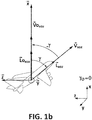
- Figure 1b shows the actual aircraft trajectory ( V ), the reference aircraft trajectory ( Vo ), the actual light beam direction ( L ), and the desired light beam direction ( Lo ) -corresponding to the reference aircraft trajectory ( Vo ) - in the horizontal plane XZ.
- the aircraft following the actual aircraft trajectory ( V ) forms an angle ⁇ with the horizontal axis y
- the reference -desired as per light beam default orientation- aircraft trajectory ( Vo ) forms an angle ⁇ 0 with the horizontal axis y
- the actual aircraft trajectory ( V ) is deviated
- the light beam direction ( L ) is corrected to achieve the desired light beam direction ( Lo ) , where this desired light beam direction ( Lo ) corresponds to the deviation of a value of lyl about the horizontal axis ( x ), following the opposite direction defined by the angular movement performed from the actual horizontal approach angle ( ⁇ ) towards the horizontal axis ( x ).
- the light beam direction is horizontally aligned towards the direction of the runway selected for takeoff or landing.
- the light source is mechanically movable, and is configured to move according to a received servo command.
- the light source has an orientable output beam consisting of an electronically controlled matrix of LEDs (with not mechanically movable parts).
- the light source may consist of an electronically controlled matrix of laser diodes, or a projection via LCD, or a micro mirror electronically controlled.
- control unit is connected to the flight management system data of the aircraft, to determine the runway (R) selected for takeoff or landing, and/or its orientation ( R ).
- control unit is configured to automatically turn on the light source in approach, landing and take-off phases based on the information received from the flight management system, in particular, from altitude and distance to target runway information.
- control unit is further configured to perform auto-dimming functions to avoid glaring another aircrafts in the airport after the landing has been performed, or before the acceleration phase of the take-off. These phases are detected by the information provided by the flight management system.
- Figure 2 shows a second scenery where the aircraft is not oriented to be aligned with the direction of the runway selected for takeoff or landing ( R ), and for that, in which the light flux ( L ) needs to be corrected by ⁇ (along the pitch axis) and ⁇ (along the yaw axis) with respect to the desired light beam direction ( Lo ) , considering the relative position of the aircraft towards the runway orientation.
- ( L ) is the basic direction of the light flux defined in the aircraft (the one that exists today -and the right direction when the aircraft is oriented in the direction of the runway selected for takeoff or landing-), and is then corrected with the aircraft attitude, so that,
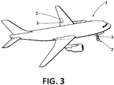
- Figure 3 shows an aircraft (1) having parts (2) in which a dynamic illumination system (3) for runway illumination as described above may be embedded.
- Said dynamic illumination system (3) may be embedded on a movable or not movable part (2) of the aircraft (1).
Landscapes
- Engineering & Computer Science (AREA)
- Aviation & Aerospace Engineering (AREA)
- General Engineering & Computer Science (AREA)
- Traffic Control Systems (AREA)
- Circuit Arrangement For Electric Light Sources In General (AREA)
- Non-Portable Lighting Devices Or Systems Thereof (AREA)
Abstract
The invention refers to a dynamic illumination system (1) for runway illumination, comprising a light source having an addressable light beam direction ( L ), and a control unit configured to: receive aircraft attitude information and the orientation of the runway selected for takeoff or landing ( R ); obtain horizontal ( x ) and vertical axes ( y ), x being collinear with the longitudinal direction of R ; determine the actual aircraft trajectory ( V ) and the reference aircraft trajectory ( V o); obtain the actual vertical approach angle (β), the reference vertical approach angle (β0), and the actual horizontal approach angle (γ); and actuate onto the light source to perform an angular movement in the light beam direction ( L ) of a value of |β|-|β0| about the vertical axis ( y ), and an angular movement of a value of lyl about the horizontal axis ( x ), to vertically and horizontally align the beam of the light source towards the runway direction.
Description
- The present invention refers to a dynamic illumination system for runway illumination. More particularly, the invention is relative to an aircraft illumination system for runway illumination for take-off and landing purposes.
- One object of the invention is to provide an architecture for runway illumination that is more efficient and best adapted to all aircraft attitudes considering its velocity vector.
- Another object of the invention is to provide an architecture for runway illumination that improves the illumination performances in any external environmental conditions, also in low visibility scenarios.
- Currently, two main solutions exists for the dynamic illumination of a runway, one solution is based in the use of MEMs (Micro-Electro-Mechanical Systems) computation, and another one is based in image recognition. The first solution requires MEMs technology embedded within the light to estimate the relative position and attitude of the aircraft to the runway in order to adapt the illumination accordingly, while the second solution consists of embedding a camera in a light, and recognize the runway by image post treatment to orient the light beam accordingly.
- Both solutions requires the integration of complex architectures in a light.
- In addition, these both solutions are not robust to all aircraft attitudes, due to the low reliability of the techniques that are used. In particular, a lot of bias are present on the MEMs technique, and several low visibility issues are experienced due to the weather conditions in the video recognition technique.
- Further, lights to illuminate the runway are usually designed for a specific reference scenario of attitude of the aircraft for take-off and landing phase, and this reference orientation of the light beam is not always the best adapted to the actual attitude of the aircraft (given by its velocity vector); an example is landing with cross wind or landing at higher velocity (different pitch approach than reference scenario).
- It would therefore be desirable to provide technical means that are simple, efficient at all aircraft attitudes, and that are capable of withstanding environment conditions without being operationally affected.
- The present invention overcomes the above mentioned drawbacks by providing a dynamic illumination system for runway illumination that solves the above identified limitations of the state of the art.
- The present invention refers to a dynamic illumination system that comprises a light source having an addressable light beam direction, and a control unit configured to:
- receive aircraft attitude information, the runway (R) selected for takeoff or landing, and said runway orientation (
R ), - obtain horizontal (
x ) and vertical axes (y ), the horizontal axis (x ) being collinear with the longitudinal direction of the selected runway (R ), - determine the actual aircraft trajectory (
V ) and the reference aircraft trajectory (V o) in the horizontal and vertical axes (x ,y ) from the aircraft attitude information, - obtain the actual vertical approach angle (β) formed between projection in the X-Y plane of the actual aircraft trajectory (
V ) and the horizontal axis (x ), and the reference vertical approach angle (β0) formed between the reference aircraft trajectory (Vo ) and the horizontal axis (x ), - obtain the actual horizontal approach angle (γ) formed between the projection of the aircraft trajectory (
V ) in the X-Z plane and the horizontal axis (x ), - actuate onto the light source to perform an angular movement in the light beam direction (
L ) of a value of |β|-|β0| about the vertical axis (y ) following the direction defined by the angular movement performed from the actual approach angle (β) towards the reference approach angle (β0), to vertically align the beam of the light source towards the runway direction, - and, actuate onto the light source to perform an angular movement in the light beam direction (
L ) of a value of |γ| about the horizontal axis (x ) following the opposite direction defined by the angular movement performed from the actual horizontal approach angle (γ) towards the horizontal axis (x ), to horizontally align the beam of the light source towards the runway direction. - This way, the invention provides a dynamic illumination system adapted to orient the light beam towards the direction of the runway selected for takeoff or landing considering the aircraft trajectory at any time.
- Further, since the light source of the system is connected to aircraft existing data to know the attitude of the aircraft, and to the flight management system data to know, via the QFU code (magnetic orientation compared to north, clockwise), which runway has been selected and how it is oriented, the invention provides an easier and a more reliable way of orienting the light beam towards the current and correct direction of the runway in comparison with the state of the art solutions.
- For a better comprehension of the invention, the following drawings are provided for illustrative and non-limiting purposes, wherein:
-
Figure 1 shows, in horizontal and vertical planes, the vectors considered in a first scenery where the actual aircraft trajectory (V ) is diverged from the reference aircraft trajectory (V o) associated to a specific aircraft attitude.Figure 1 a shows the vectors in a vertical plane.Figure 1b shows the vectors in a horizontal plane. -
Figure 2 shows altogether the vectors considered in a second scenery where the actual aircraft trajectory (V ) is diverged from the reference aircraft trajectory (V o) associated to a specific aircraft attitude. -
Figure 3 shows an aircraft having the dynamic illumination system embedded in one of its parts. - According to the invention, the illumination system comprises a light source, and a control unit. The light source has an addressable light beam direction (
L ) that being steerable provides a dynamic illumination, sensitive to the actual aircraft attitude information, and the orientation of the runway (R ) selected for takeoff or landing. -
Figure 1 schematically shows a first scenery in which an aircraft follows a trajectory deviated from the reference -desired- trajectory. Consequently, the light beam direction is also deviated from the reference -desired- direction considering the aircraft trajectory. -
Figure 1a shows the actual aircraft trajectory (V ), the reference aircraft trajectory (Vo ), the actual light beam direction (L ), and the reference light beam direction (Lo ), wherein the reference light beam direction (Lo ) corresponds to the reference aircraft trajectory (Vo ) in the vertical plane XY. As reference, horizontal axis (x ) is collinear with the longitudinal direction of the selected runway (R ). - As shown, the aircraft following the actual aircraft trajectory (
V ) forms an angle β with the horizontal axisx , while the reference -desired as per light orientation default design- aircraft trajectory (Vo ) forms an angle β0 with the horizontal axisx . Thus, the actual aircraft trajectory (V ) is deviated |β|-|β0| from the reference -desired- aircraft trajectory (Vo ). Accordingly, the light beam direction (L ) is corrected to achieve the desired light beam direction (Lo ), where this desired light beam direction (Lo ) corresponds to the deviation of a value of |β|-|β0| about the vertical axis (y ), following the direction defined by the angular movement performed from the actual approach angle (β) towards the reference -desired- approach angle (β0) of the light beam direction (L ). This way, the light beam direction is vertically aligned towards the direction of the runway selected for takeoff or landing. -
Figure 1b shows the actual aircraft trajectory (V ), the reference aircraft trajectory (Vo ), the actual light beam direction (L ), and the desired light beam direction (Lo ) -corresponding to the reference aircraft trajectory (Vo ) - in the horizontal plane XZ. - As shown, the aircraft following the actual aircraft trajectory (
V ) forms an angle γ with the horizontal axisy , while the reference -desired as per light beam default orientation- aircraft trajectory (Vo ) forms an angle γ0 with the horizontal axisy . Thus, the actual aircraft trajectory (V ) is deviated |γ|-|γ0| from the reference - desired- aircraft trajectory (Vo ). Accordingly, the light beam direction (L ) is corrected to achieve the desired light beam direction (Lo ), where this desired light beam direction (Lo ) corresponds to the deviation of a value of lyl about the horizontal axis (x ), following the opposite direction defined by the angular movement performed from the actual horizontal approach angle (γ) towards the horizontal axis (x ). This way, the light beam direction is horizontally aligned towards the direction of the runway selected for takeoff or landing. - According to a preferred embodiment, the light source is mechanically movable, and is configured to move according to a received servo command.
- According to another preferred embodiment, the light source has an orientable output beam consisting of an electronically controlled matrix of LEDs (with not mechanically movable parts). Alternatively, the light source may consist of an electronically controlled matrix of laser diodes, or a projection via LCD, or a micro mirror electronically controlled.
- Also, according to another preferred embodiment, the control unit is connected to the flight management system data of the aircraft, to determine the runway (R) selected for takeoff or landing, and/or its orientation (
R ). - According to another preferred embodiment, the control unit is configured to automatically turn on the light source in approach, landing and take-off phases based on the information received from the flight management system, in particular, from altitude and distance to target runway information.
- According to another preferred embodiment, the control unit is further configured to perform auto-dimming functions to avoid glaring another aircrafts in the airport after the landing has been performed, or before the acceleration phase of the take-off. These phases are detected by the information provided by the flight management system.
-
Figure 2 shows a second scenery where the aircraft is not oriented to be aligned with the direction of the runway selected for takeoff or landing (R ), and for that, in which the light flux (L ) needs to be corrected by β (along the pitch axis) and γ (along the yaw axis) with respect to the desired light beam direction (Lo ), considering the relative position of the aircraft towards the runway orientation. - As mention, to obtain the desired light beam direction (
Lo ) starts with (L ), which is the basic direction of the light flux defined in the aircraft (the one that exists today -and the right direction when the aircraft is oriented in the direction of the runway selected for takeoff or landing-), and is then corrected with the aircraft attitude, so that, - if the aircraft trajectory (speed vector, (
V )) is tilted upwards such that an angle γ is formed compared to the horizontal plan defined by the runway, the vectorL is corrected by to keep the focus down; and inversely to keep the focus up if it is tilted downwards), - and if the aircraft trajectory (speed vector, (
V )) is laterally moved such that an angle γ is formed compared to a vertical plan perpendicular to the wings and to the fuselage reference line, the vectorL is corrected by at +/- |γ| to focus the light accordingly. -
Figure 3 shows an aircraft (1) having parts (2) in which a dynamic illumination system (3) for runway illumination as described above may be embedded. Said dynamic illumination system (3) may be embedded on a movable or not movable part (2) of the aircraft (1).
Claims (7)
- Dynamic illumination system for runway illumination, comprising:- a light source having an addressable light beam direction (
L ),- a control unit configured to:- receive aircraft attitude information, the runway (R) selected for takeoff or landing, and said runway orientation (R ),- obtain horizontal (x ) and vertical axes (y ), the horizontal axis (x ) being collinear with the longitudinal direction of the selected runway (R ),- determine the actual aircraft trajectory (V ) and the reference aircraft trajectory (Vo ) in the horizontal and vertical axes (x ,y ) from the aircraft attitude information,- obtain the actual vertical approach angle (β) formed between projection in the X-Y plane of the actual aircraft trajectory (V ) and the horizontal axis (x ), and the reference vertical approach angle (β0) formed between the reference aircraft trajectory (Vo ) and the horizontal axis (x ),- obtain the actual horizontal approach angle (γ) formed between the projection of the aircraft trajectory (V ) in the X-Z plane and the horizontal axis (x ),- actuate onto the light source to perform an angular movement in the light beam direction (L ) of a value of |β|-|β0| about the vertical axis (y ) following the direction defined by the angular movement performed from the actual approach angle (β) towards the reference approach angle (β0), to vertically align the beam of the light source towards the runway direction,- and, actuate onto the light source to perform an angular movement in the light beam direction (L ) of a value of |γ| about the horizontal axis (x ) following the opposite direction defined by the angular movement performed from the actual horizontal approach angle (γ) towards the horizontal axis (x ), to horizontally align the beam of the light source towards the runway direction. - Dynamic illumination system for runway illumination, according to claim 1, wherein the light source is mechanically movable, and is configured to move according to a received servo command.
- Dynamic illumination system for runway illumination, according to claim 1, wherein the light source has an orientable output beam, preferably consisting of an electronically controlled matrix of LEDs or laser diodes, a projection via LCD, or micro mirror electronically controlled.
- Dynamic illumination system for runway illumination, according to any preceding claims, wherein the control unit is connected to the flight management system data of the aircraft, to determine the runway (R) selected for takeoff or landing, and/or its orientation (
R ). - Dynamic illumination system for runway illumination, according to claim 4, wherein the control unit is configured to automatically turn on the light source in approach, landing and take-off phases based on the information received from the flight management system.
- Dynamic illumination system for runway illumination, according to any of claims 4 to 5, wherein the control unit is further configured to perform auto-dimming functions to avoid glaring another aircrafts in the airport.
- An aircraft part (2) comprising the dynamic illumination system (3) for runway illumination according to any of the preceding claims, said dynamic illumination system (3) being embedded in the aircraft part (2).
Priority Applications (3)
| Application Number | Priority Date | Filing Date | Title |
|---|---|---|---|
| EP19382266.5A EP3722211A1 (en) | 2019-04-10 | 2019-04-10 | Dynamic illumination system for runway illumination |
| US16/842,173 US11542033B2 (en) | 2019-04-10 | 2020-04-07 | Dynamic illumination system for runway illumination |
| CN202010279865.1A CN111806709B (en) | 2019-04-10 | 2020-04-10 | Dynamic lighting system and aircraft component for runway lighting |
Applications Claiming Priority (1)
| Application Number | Priority Date | Filing Date | Title |
|---|---|---|---|
| EP19382266.5A EP3722211A1 (en) | 2019-04-10 | 2019-04-10 | Dynamic illumination system for runway illumination |
Publications (1)
| Publication Number | Publication Date |
|---|---|
| EP3722211A1 true EP3722211A1 (en) | 2020-10-14 |
Family
ID=66397185
Family Applications (1)
| Application Number | Title | Priority Date | Filing Date |
|---|---|---|---|
| EP19382266.5A Withdrawn EP3722211A1 (en) | 2019-04-10 | 2019-04-10 | Dynamic illumination system for runway illumination |
Country Status (3)
| Country | Link |
|---|---|
| US (1) | US11542033B2 (en) |
| EP (1) | EP3722211A1 (en) |
| CN (1) | CN111806709B (en) |
Families Citing this family (2)
| Publication number | Priority date | Publication date | Assignee | Title |
|---|---|---|---|---|
| US11192494B2 (en) | 2020-02-07 | 2021-12-07 | Honeywell International Inc. | Systems and methods for search and landing light |
| US11472333B1 (en) * | 2021-04-01 | 2022-10-18 | Honeywell International Inc. | Searchlight control systems and methods for moving a beam of light emitted by a searchlight on a mobile platform at a constant ground speed |
Citations (5)
| Publication number | Priority date | Publication date | Assignee | Title |
|---|---|---|---|---|
| US20150146442A1 (en) * | 2013-11-15 | 2015-05-28 | Zodiac Aero Electric | Optical lighting system for an aircraft |
| EP2995501A1 (en) * | 2014-09-15 | 2016-03-16 | Goodrich Lighting Systems GmbH | Dynamic aircraft headlight and method of operating a dynamic aircraft headlight |
| EP3141485A1 (en) * | 2015-09-10 | 2017-03-15 | Goodrich Lighting Systems GmbH | Dynamic exterior aircraft light unit and method of operating a dynamic exterior aircraft light unit |
| US9643736B1 (en) * | 2016-04-14 | 2017-05-09 | Goodrich Corporation | Systems and methods for landing lights |
| EP3168529A1 (en) * | 2012-02-07 | 2017-05-17 | Two Trees Photonics Limited | Lighting device |
Family Cites Families (4)
| Publication number | Priority date | Publication date | Assignee | Title |
|---|---|---|---|---|
| US20080137353A1 (en) * | 2006-12-08 | 2008-06-12 | Larsen Ty A | Multi-mode exterior lighting architectures for aircraft |
| KR20140138572A (en) * | 2014-11-12 | 2014-12-04 | 김태진 | Airport Flight Approach Lighting Apparatus |
| FR3057546B1 (en) * | 2016-10-19 | 2021-12-31 | Zodiac Aero Electric | MULTIFUNCTIONAL RUNWAY LIGHT WITH STATIC FUNCTION SWITCHING FOR AIRCRAFT |
| CN207089674U (en) * | 2017-08-07 | 2018-03-13 | 曹树春 | A kind of aircraft laser lamp |
-
2019
- 2019-04-10 EP EP19382266.5A patent/EP3722211A1/en not_active Withdrawn
-
2020
- 2020-04-07 US US16/842,173 patent/US11542033B2/en active Active
- 2020-04-10 CN CN202010279865.1A patent/CN111806709B/en active Active
Patent Citations (5)
| Publication number | Priority date | Publication date | Assignee | Title |
|---|---|---|---|---|
| EP3168529A1 (en) * | 2012-02-07 | 2017-05-17 | Two Trees Photonics Limited | Lighting device |
| US20150146442A1 (en) * | 2013-11-15 | 2015-05-28 | Zodiac Aero Electric | Optical lighting system for an aircraft |
| EP2995501A1 (en) * | 2014-09-15 | 2016-03-16 | Goodrich Lighting Systems GmbH | Dynamic aircraft headlight and method of operating a dynamic aircraft headlight |
| EP3141485A1 (en) * | 2015-09-10 | 2017-03-15 | Goodrich Lighting Systems GmbH | Dynamic exterior aircraft light unit and method of operating a dynamic exterior aircraft light unit |
| US9643736B1 (en) * | 2016-04-14 | 2017-05-09 | Goodrich Corporation | Systems and methods for landing lights |
Also Published As
| Publication number | Publication date |
|---|---|
| US20200324912A1 (en) | 2020-10-15 |
| US11542033B2 (en) | 2023-01-03 |
| CN111806709B (en) | 2024-06-04 |
| CN111806709A (en) | 2020-10-23 |
Similar Documents
| Publication | Publication Date | Title |
|---|---|---|
| US12236795B2 (en) | Autonomous path planning | |
| CN107380468B (en) | System and method for landing light | |
| EP3424814A1 (en) | Unmanned air vehicle, unmanned air vehicle control system, flight control method, and program storage medium | |
| US8686326B1 (en) | Optical-flow techniques for improved terminal homing and control | |
| ES2612163T3 (en) | Procedure and steering system of an unmanned aerial vehicle | |
| CN102582826A (en) | Driving method and system of four-rotor-wing unmanned flight vehicle | |
| KR20140035069A (en) | Smart helipad for supporting landing of aircraft with capable of vertical take-off and landing, system including the smart helipad, and method of enabling the smart helipadng | |
| EP3868652B1 (en) | Information processing system, information processing method, and program | |
| US11542033B2 (en) | Dynamic illumination system for runway illumination | |
| CN103389732A (en) | Piloting control method of aircraft | |
| CN112306087A (en) | System and method for generating a flight path for navigating an aircraft | |
| EP3981687B1 (en) | Ballistically-deployed controllable parasail | |
| DE60204234D1 (en) | METHOD FOR FILLING A PLANE IN FLIGHT | |
| US11378959B1 (en) | Still image optimized flight paths for fixed camera UAVs | |
| US3005185A (en) | Airborne approach aid | |
| JP2000085694A (en) | Landing support sensor device and vertical landing / landing aircraft landing support system using the same | |
| CN107462245A (en) | System and method for providing from aircraft transverse direction homing capability feedback to pilot | |
| Andert et al. | Improving monocular SLAM with altimeter hints for fixed-wing aircraft navigation and emergency landing | |
| Kawamura et al. | VSLAM and Vision-based Approach and Landing for Advanced Air Mobility | |
| Wüest et al. | Accurate vision-based flight with fixed-wing drones | |
| RU2739636C1 (en) | Method of landing of an uav on a landing platform | |
| JP2019182089A (en) | Flying device and flying device guidance system | |
| US7365705B2 (en) | Flight control display | |
| US20220380065A1 (en) | Systems and methods for calibrating a synthetic image on an avionic display | |
| CN114217639A (en) | Guidance method and system for crossing visual target point based on designated course of unmanned aerial vehicle |
Legal Events
| Date | Code | Title | Description |
|---|---|---|---|
| PUAI | Public reference made under article 153(3) epc to a published international application that has entered the european phase |
Free format text: ORIGINAL CODE: 0009012 |
|
| STAA | Information on the status of an ep patent application or granted ep patent |
Free format text: STATUS: THE APPLICATION HAS BEEN PUBLISHED |
|
| AK | Designated contracting states |
Kind code of ref document: A1 Designated state(s): AL AT BE BG CH CY CZ DE DK EE ES FI FR GB GR HR HU IE IS IT LI LT LU LV MC MK MT NL NO PL PT RO RS SE SI SK SM TR |
|
| AX | Request for extension of the european patent |
Extension state: BA ME |
|
| STAA | Information on the status of an ep patent application or granted ep patent |
Free format text: STATUS: THE APPLICATION IS DEEMED TO BE WITHDRAWN |
|
| 18D | Application deemed to be withdrawn |
Effective date: 20210415 |