EP3722166A1 - Braking circuit for the braking of a vehicle - Google Patents
Braking circuit for the braking of a vehicle Download PDFInfo
- Publication number
- EP3722166A1 EP3722166A1 EP20169177.1A EP20169177A EP3722166A1 EP 3722166 A1 EP3722166 A1 EP 3722166A1 EP 20169177 A EP20169177 A EP 20169177A EP 3722166 A1 EP3722166 A1 EP 3722166A1
- Authority
- EP
- European Patent Office
- Prior art keywords
- braking
- valve means
- line
- fact
- emergency
- Prior art date
- Legal status (The legal status is an assumption and is not a legal conclusion. Google has not performed a legal analysis and makes no representation as to the accuracy of the status listed.)
- Granted
Links
Images


Classifications
-
- B—PERFORMING OPERATIONS; TRANSPORTING
- B60—VEHICLES IN GENERAL
- B60T—VEHICLE BRAKE CONTROL SYSTEMS OR PARTS THEREOF; BRAKE CONTROL SYSTEMS OR PARTS THEREOF, IN GENERAL; ARRANGEMENT OF BRAKING ELEMENTS ON VEHICLES IN GENERAL; PORTABLE DEVICES FOR PREVENTING UNWANTED MOVEMENT OF VEHICLES; VEHICLE MODIFICATIONS TO FACILITATE COOLING OF BRAKES
- B60T13/00—Transmitting braking action from initiating means to ultimate brake actuator with power assistance or drive; Brake systems incorporating such transmitting means, e.g. air-pressure brake systems
- B60T13/10—Transmitting braking action from initiating means to ultimate brake actuator with power assistance or drive; Brake systems incorporating such transmitting means, e.g. air-pressure brake systems with fluid assistance, drive, or release
- B60T13/12—Transmitting braking action from initiating means to ultimate brake actuator with power assistance or drive; Brake systems incorporating such transmitting means, e.g. air-pressure brake systems with fluid assistance, drive, or release the fluid being liquid
- B60T13/22—Brakes applied by springs or weights and released hydraulically
-
- B—PERFORMING OPERATIONS; TRANSPORTING
- B60—VEHICLES IN GENERAL
- B60T—VEHICLE BRAKE CONTROL SYSTEMS OR PARTS THEREOF; BRAKE CONTROL SYSTEMS OR PARTS THEREOF, IN GENERAL; ARRANGEMENT OF BRAKING ELEMENTS ON VEHICLES IN GENERAL; PORTABLE DEVICES FOR PREVENTING UNWANTED MOVEMENT OF VEHICLES; VEHICLE MODIFICATIONS TO FACILITATE COOLING OF BRAKES
- B60T8/00—Arrangements for adjusting wheel-braking force to meet varying vehicular or ground-surface conditions, e.g. limiting or varying distribution of braking force
- B60T8/32—Arrangements for adjusting wheel-braking force to meet varying vehicular or ground-surface conditions, e.g. limiting or varying distribution of braking force responsive to a speed condition, e.g. acceleration or deceleration
-
- B—PERFORMING OPERATIONS; TRANSPORTING
- B60—VEHICLES IN GENERAL
- B60T—VEHICLE BRAKE CONTROL SYSTEMS OR PARTS THEREOF; BRAKE CONTROL SYSTEMS OR PARTS THEREOF, IN GENERAL; ARRANGEMENT OF BRAKING ELEMENTS ON VEHICLES IN GENERAL; PORTABLE DEVICES FOR PREVENTING UNWANTED MOVEMENT OF VEHICLES; VEHICLE MODIFICATIONS TO FACILITATE COOLING OF BRAKES
- B60T8/00—Arrangements for adjusting wheel-braking force to meet varying vehicular or ground-surface conditions, e.g. limiting or varying distribution of braking force
- B60T8/32—Arrangements for adjusting wheel-braking force to meet varying vehicular or ground-surface conditions, e.g. limiting or varying distribution of braking force responsive to a speed condition, e.g. acceleration or deceleration
- B60T8/34—Arrangements for adjusting wheel-braking force to meet varying vehicular or ground-surface conditions, e.g. limiting or varying distribution of braking force responsive to a speed condition, e.g. acceleration or deceleration having a fluid pressure regulator responsive to a speed condition
- B60T8/36—Arrangements for adjusting wheel-braking force to meet varying vehicular or ground-surface conditions, e.g. limiting or varying distribution of braking force responsive to a speed condition, e.g. acceleration or deceleration having a fluid pressure regulator responsive to a speed condition including a pilot valve responding to an electromagnetic force
- B60T8/3615—Electromagnetic valves specially adapted for anti-lock brake and traction control systems
- B60T8/363—Electromagnetic valves specially adapted for anti-lock brake and traction control systems in hydraulic systems
- B60T8/3635—Electromagnetic valves specially adapted for anti-lock brake and traction control systems in hydraulic systems switching between more than two connections, e.g. 3/2-valves
-
- B—PERFORMING OPERATIONS; TRANSPORTING
- B60—VEHICLES IN GENERAL
- B60T—VEHICLE BRAKE CONTROL SYSTEMS OR PARTS THEREOF; BRAKE CONTROL SYSTEMS OR PARTS THEREOF, IN GENERAL; ARRANGEMENT OF BRAKING ELEMENTS ON VEHICLES IN GENERAL; PORTABLE DEVICES FOR PREVENTING UNWANTED MOVEMENT OF VEHICLES; VEHICLE MODIFICATIONS TO FACILITATE COOLING OF BRAKES
- B60T8/00—Arrangements for adjusting wheel-braking force to meet varying vehicular or ground-surface conditions, e.g. limiting or varying distribution of braking force
- B60T8/32—Arrangements for adjusting wheel-braking force to meet varying vehicular or ground-surface conditions, e.g. limiting or varying distribution of braking force responsive to a speed condition, e.g. acceleration or deceleration
- B60T8/34—Arrangements for adjusting wheel-braking force to meet varying vehicular or ground-surface conditions, e.g. limiting or varying distribution of braking force responsive to a speed condition, e.g. acceleration or deceleration having a fluid pressure regulator responsive to a speed condition
- B60T8/36—Arrangements for adjusting wheel-braking force to meet varying vehicular or ground-surface conditions, e.g. limiting or varying distribution of braking force responsive to a speed condition, e.g. acceleration or deceleration having a fluid pressure regulator responsive to a speed condition including a pilot valve responding to an electromagnetic force
- B60T8/3615—Electromagnetic valves specially adapted for anti-lock brake and traction control systems
- B60T8/363—Electromagnetic valves specially adapted for anti-lock brake and traction control systems in hydraulic systems
- B60T8/3645—Electromagnetic valves specially adapted for anti-lock brake and traction control systems in hydraulic systems having more than one electromagnetic coil inside a common housing
Definitions
- the present invention relates to a braking circuit for the braking of a vehicle.
- these braking circuits of known type comprise a supply line for a pressurized work fluid, connected for example to a corresponding pump, a discharge line and valve means adapted to place selectively the spring-loaded brake in communication with the supply line and with the discharge line.
- the valve means are therefore movable between a release position, wherein the supply line is placed in communication with the spring-loaded brake to allow the compression of the latter and the consequent release of the brake, and a braking position, wherein the spring-loaded brake is placed in communication with the discharge line, as a result of which the spring expands so as to actuate the brake.
- the valve means are provided with electrically-operated command means to displace them from the braking position to the release position.
- valve means are, under normal operating condition, in the braking position, while they are switched to the release position as a result of the activation of the electrical command means.
- the electrical command means are generally composed of a solenoid provided with a relevant winding.
- valve means displace independently to the braking position, thus interrupting the vehicle's run.
- the malfunction of the electrical command means can therefore lead to the undesired braking of the vehicle even if the fluid-operated system does not have any malfunction and can therefore perform its function properly.
- a solution of known type requires that the enabling solenoid valve is normally open, in which case high energy is required to keep the brake released.
- the enabling solenoid valve is of the normally closed type, however, it is necessary to switch the enabling solenoid valve to activate the braking.
- the main aim of the present invention is to devise a braking circuit which allows solving the aforementioned problems and in particular which allows keeping the brake deactivated in the case of an electrical malfunction and, at the same time, reducing the energy expenditure compared to known solutions.
- one object of the present invention is to allow the brake to be manually deactivated in case of need.
- Another object of the present invention is to devise a circuit that allows the service braking to be used as an emergency brake in case of need.
- Another object of the present invention is to devise a braking circuit that allows overcoming the aforementioned drawbacks of the prior art in a simple, rational, easy, effective to use and low cost solution.
- reference numeral 1 globally indicates a braking circuit for the braking of a vehicle.
- the circuit 1 comprises at least one supply line 2 of a pressurized work fluid, e.g. connected to a pump P, at least one discharge line 3, at least one braking line 4 communicating with a braking device 5 and main valve means 6 which can be moved between a braking position, wherein they place the braking line 4 in communication with the discharge line 3, and a release position, wherein they place the braking line 4 in communication with the supply line 2.
- the braking device 5 corresponds to the braking device of a self-propelled vehicle.
- main valve means 6 are interposed between the braking line 4 and the supply and discharge lines 2, 3.
- the braking device 5 is of the type of a spring-loaded brake with hydraulic release (SAHR), which is adapted to activate braking in said braking position. More in detail, this type of braking device 5 comprises a spring element 7 which, in home condition, causes the activation of a corresponding brake (not visible in detail in the figures). To release the brake, therefore, it is necessary to convey pressurized fluid along the braking line 4 so as to cause the compression of the spring element 7.
- SAHR spring-loaded brake with hydraulic release
- the braking line 4 corresponds to the additional line of a trailer-brake valve, of the type known to the technician in the sector.
- the circuit 1 also comprises main command means 8 which can be operated to bring the main valve means 6 from the braking position to the release position.
- the main command means 8 are therefore adapted to switch the status of the main valve means 6 as a result of the activation by an operator.
- first elastic means 9 are provided adapted to push the main valve means 6 towards the braking position.
- the main command means 8 therefore counteract the first elastic means 9 to move the main valve means 6 from the braking position to the release position.
- the main command means 8 comprise first and second electrical command means, identified in the figures with reference numerals 8a and 8b respectively, operating on the main valve means 6 and actuatable independently to each other.
- the first and second command means 8a and 8b comprise a single solenoid adapted to actuate at least one movable core 22 connected to the main valve means 6 and a first and second winding, identified with reference numerals 21a and 21b, respectively, that can be activated independently to each other to move the movable core.
- the first and second command means 8a and 8b each comprise a relevant solenoid provided with a relevant winding, 21a and 21b respectively, which, due to the passage of the current inside it, creates a magnetic field adapted to move the movable core, 22a and 22b respectively, of the relevant solenoid.
- the force exertable by each of the first and second command means 8a and 8b is sufficient to keep the main valve means 6 in the release position and is insufficient to move the main valve means themselves from the braking position to the release position.
- any malfunction of one of the first and second command means 8a, 8b does not cause the main valve means 6 to switch to the braking position because the force exerted by the first or by the second command means 8a, 8b remaining active is sufficient to keep them in the release position.
- this allows reducing the energy consumption required to keep the main valve means 6 in the release position.
- the main command means 8 comprise at least one manual command 8c that can be actuated to move the main valve means 6 from the braking position to the release position.
- the manual command 8c which may be of the type of a push-button manually actuated by an operator, therefore allows the main valve means 6 to be displaced from the braking position to the release position also in the event that one of either the first or the second command means 8a and 8b is malfunctioning but the operator verifies that the fluid-operated system is operational and able to operate correctly.
- the circuit 1 also comprises emergency valve means 10 arranged in series with the main valve means 6 and placed between the supply line 2 and the braking line 4, which are adapted to activate the emergency braking in case of need.
- At least one additional discharge line 11, which may be separate from or coincide with the discharge line 3, is also provided in these embodiments, and the emergency valve means 10 are movable between at least one home position, wherein they are adapted to allow the passage of the work fluid towards the braking line 4, and an emergency position, wherein they are adapted to allow the passage of the work fluid towards the additional discharge line 11.
- the emergency valve means 10 are able (the actual connection therebetween can also depend on the position of the main valve means 8) to place the supply line 2 in communication with the braking line 4 while in the emergency position they are adapted to allow the passage of the work fluid towards the additional discharge line 11.
- the emergency valve means 10 are adapted to insulate the additional discharge line 3 from the braking line 4, while in the emergency position they are adapted to insulate the supply line 2 from the braking line 4.
- the emergency valve means 10 are of the proportional type and the circuit 1 comprises emergency command means 12 that can be operated to displace the emergency valve means 10 from the home position to the braking position.
- connection line 13 is placed between the main valve means 6 and the emergency valve means 10.
- the emergency valve means 10 are placed between the main valve means 6 and the braking line 4.
- the emergency valve means 10 are adapted to place the connection line 13 in communication with the braking line 4 in the home position and the braking line 4 with the additional discharge line 11 in the emergency position.
- the emergency valve means 10 also have an intermediate position with respect to the home and emergency positions, wherein the connection line 13, the braking line 4 and the additional discharge line 11 are insulated from each other.
- the emergency command means 12 are of the mechanical type. More specifically, the emergency command means 12 are of the type of a hand lever, on which a plurality of elastic elements 14 operate.
- At least one one-way valve 16 is located between the driving line 15 and the connection line 13, which valve is adapted to allow the flow of the work fluid towards the main valve means 6.
- This one-way valve 16 is adapted to allow the passage of the work fluid from the braking line 4 to the discharge line 3, if necessary, when the emergency valve means 10 are in the intermediate position during the transition from the home position to the emergency position.
- the main valve means 6 are placed between the emergency valve means 10 and the braking line 4 and the emergency valve means 10 are adapted to place the connection line 13 in communication with the supply line 2 in the home position and the connection line 13 with the additional discharge line 11 in the emergency position.
- valve 6 since the valve 6 is of the ON/OFF type (i.e. it has only two positions) it is not necessary to have a one-way valve.
- the emergency command means 12 are of the electro-hydraulic type. More specifically, the emergency command means 12 comprise at least one solenoid valve 17 and at least one driving line 18 communicating with the connection line 13 operating in parallel on the emergency valve means 10. On the emergency valve means, on the opposite side of the emergency command means 12, second elastic means 19 operate.
- both the first and second command means 8a and 8b are activated to allow the displacement thereof, so as to switch the status of the main valve means 6 from the braking position to the release position.
- the main valve means 6 place the supply line 2 in communication with the braking line 4, thus causing the spring element 7 to compress and, consequently, to release the brake.
- any malfunction of one of the command means 8a and 8b will not cause the main valve means 6 to return to the braking position, as the force exerted by the other of either the command means 8a or 8b is sufficient to keep them in the release position.
- the emergency valve means 10 allow the service brake to be used as an emergency brake if necessary.
- the operator is able to displace the emergency valve means 10 from the home position to the emergency position in order to allow the outflow of the work fluid towards the additional discharge line 11.
- the activation of the emergency command means 12 causes that the connection line 13 is placed in communication with the additional discharge line 11.
- the corresponding brake is activated regardless of the position of the emergency valve means, while when the main valve means 6 are in the release position, the brake is activated only after the emergency valve means 10 have been displaced to the emergency position.
- the described invention achieves the intended objects and, in particular, it is underlined that the braking circuit which the present invention relates to, makes it possible to avoid undesired braking of the vehicle in the event of malfunction of the electrical commands of the relevant valve means, while at the same time reducing energy expenditure.
Landscapes
- Engineering & Computer Science (AREA)
- Transportation (AREA)
- Mechanical Engineering (AREA)
- Braking Systems And Boosters (AREA)
- Braking Arrangements (AREA)
- Valves And Accessory Devices For Braking Systems (AREA)
Abstract
Description
- The present invention relates to a braking circuit for the braking of a vehicle.
- In vehicles of known type, the use of braking circuits is known provided with spring-loaded brakes with hydraulic release (called SAHR). This type of brakes is characterized by the fact that the braking is deactivated and activated, respectively, after compression and release of the relevant spring.
- In particular, these braking circuits of known type comprise a supply line for a pressurized work fluid, connected for example to a corresponding pump, a discharge line and valve means adapted to place selectively the spring-loaded brake in communication with the supply line and with the discharge line. The valve means are therefore movable between a release position, wherein the supply line is placed in communication with the spring-loaded brake to allow the compression of the latter and the consequent release of the brake, and a braking position, wherein the spring-loaded brake is placed in communication with the discharge line, as a result of which the spring expands so as to actuate the brake.
- The valve means are provided with electrically-operated command means to displace them from the braking position to the release position.
- More specifically, the valve means are, under normal operating condition, in the braking position, while they are switched to the release position as a result of the activation of the electrical command means.
- The electrical command means are generally composed of a solenoid provided with a relevant winding.
- These devices of known type do have some drawbacks.
- In fact, in the event of a malfunction or breakage of the electrical command means, the valve means displace independently to the braking position, thus interrupting the vehicle's run.
- The malfunction of the electrical command means can therefore lead to the undesired braking of the vehicle even if the fluid-operated system does not have any malfunction and can therefore perform its function properly.
- A number of alternative solutions have been adopted to overcome this drawback.
- Some of these alternative solutions involve the use of an enabling solenoid valve arranged in series with the valve means described above and independently energized.
- In particular, a solution of known type requires that the enabling solenoid valve is normally open, in which case high energy is required to keep the brake released.
- In an alternative solution, the enabling solenoid valve is of the normally closed type, however, it is necessary to switch the enabling solenoid valve to activate the braking.
- The main aim of the present invention is to devise a braking circuit which allows solving the aforementioned problems and in particular which allows keeping the brake deactivated in the case of an electrical malfunction and, at the same time, reducing the energy expenditure compared to known solutions. Within this aim, one object of the present invention is to allow the brake to be manually deactivated in case of need.
- Another object of the present invention is to devise a circuit that allows the service braking to be used as an emergency brake in case of need.
- Another object of the present invention is to devise a braking circuit that allows overcoming the aforementioned drawbacks of the prior art in a simple, rational, easy, effective to use and low cost solution.
- The aforementioned objects are achieved by the present braking circuit according to
claim 1. - Other characteristics and advantages of the present invention will be more evident from the description of a preferred, but not exclusive, embodiment of a braking circuit, illustrated by way of an indicative, yet non-limiting example in the attached tables of drawings in which:
-
Figure 1 is a schematic representation of a braking circuit according to the invention, in a first embodiment; -
Figure 2 is a schematic representation of a braking circuit according to the invention, in a second embodiment; -
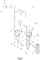
Figure 3 is a schematic representation of a braking circuit according to the invention, in a third embodiment; -
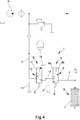
Figure 4 is a schematic representation of a braking circuit according to the invention, in a fourth embodiment. - With particular reference to these figures,
reference numeral 1 globally indicates a braking circuit for the braking of a vehicle. - The
circuit 1 comprises at least onesupply line 2 of a pressurized work fluid, e.g. connected to a pump P, at least onedischarge line 3, at least onebraking line 4 communicating with abraking device 5 and main valve means 6 which can be moved between a braking position, wherein they place thebraking line 4 in communication with thedischarge line 3, and a release position, wherein they place thebraking line 4 in communication with thesupply line 2. Appropriately, thebraking device 5 corresponds to the braking device of a self-propelled vehicle. - More specifically, the main valve means 6 are interposed between the
braking line 4 and the supply anddischarge lines - Preferably, the
braking device 5 is of the type of a spring-loaded brake with hydraulic release (SAHR), which is adapted to activate braking in said braking position. More in detail, this type ofbraking device 5 comprises aspring element 7 which, in home condition, causes the activation of a corresponding brake (not visible in detail in the figures). To release the brake, therefore, it is necessary to convey pressurized fluid along thebraking line 4 so as to cause the compression of thespring element 7. - In an alternative embodiment, not shown in the figures, the
braking line 4 corresponds to the additional line of a trailer-brake valve, of the type known to the technician in the sector. - The
circuit 1 also comprises main command means 8 which can be operated to bring the main valve means 6 from the braking position to the release position. The main command means 8 are therefore adapted to switch the status of the main valve means 6 as a result of the activation by an operator. - Appropriately, first
elastic means 9 are provided adapted to push the main valve means 6 towards the braking position. The main command means 8 therefore counteract the firstelastic means 9 to move the main valve means 6 from the braking position to the release position. - According to the invention, the main command means 8 comprise first and second electrical command means, identified in the figures with
reference numerals - In the preferred embodiment shown in
Figure 1a , the first and second command means 8a and 8b comprise a single solenoid adapted to actuate at least onemovable core 22 connected to the main valve means 6 and a first and second winding, identified withreference numerals - In an alternative embodiment, shown in
Figure 1b , the first and second command means 8a and 8b each comprise a relevant solenoid provided with a relevant winding, 21a and 21b respectively, which, due to the passage of the current inside it, creates a magnetic field adapted to move the movable core, 22a and 22b respectively, of the relevant solenoid. - Advantageously, the force exertable by each of the first and second command means 8a and 8b is sufficient to keep the main valve means 6 in the release position and is insufficient to move the main valve means themselves from the braking position to the release position. This means that when the main valve means 6 are in the release position, any malfunction of one of the first and second command means 8a, 8b does not cause the main valve means 6 to switch to the braking position because the force exerted by the first or by the second command means 8a, 8b remaining active is sufficient to keep them in the release position. At the same time this allows reducing the energy consumption required to keep the main valve means 6 in the release position.
- At the same time, when the main valve means 6 are in the braking position, the malfunction of one of either the first or the second command means 8a and 8b prevents these from switching to the release position.
- Appropriately, in the embodiment shown in
Figure 2 , the main command means 8 comprise at least onemanual command 8c that can be actuated to move the main valve means 6 from the braking position to the release position. Themanual command 8c, which may be of the type of a push-button manually actuated by an operator, therefore allows the main valve means 6 to be displaced from the braking position to the release position also in the event that one of either the first or the second command means 8a and 8b is malfunctioning but the operator verifies that the fluid-operated system is operational and able to operate correctly. - In the embodiments shown in
Figures 3 and4 , thecircuit 1 also comprises emergency valve means 10 arranged in series with the main valve means 6 and placed between thesupply line 2 and thebraking line 4, which are adapted to activate the emergency braking in case of need. At least oneadditional discharge line 11, which may be separate from or coincide with thedischarge line 3, is also provided in these embodiments, and the emergency valve means 10 are movable between at least one home position, wherein they are adapted to allow the passage of the work fluid towards thebraking line 4, and an emergency position, wherein they are adapted to allow the passage of the work fluid towards theadditional discharge line 11. - In particular, in the home position, the emergency valve means 10 are able (the actual connection therebetween can also depend on the position of the main valve means 8) to place the
supply line 2 in communication with thebraking line 4 while in the emergency position they are adapted to allow the passage of the work fluid towards theadditional discharge line 11. - In other words, in the home position, the emergency valve means 10 are adapted to insulate the
additional discharge line 3 from thebraking line 4, while in the emergency position they are adapted to insulate thesupply line 2 from thebraking line 4. - Preferably, the emergency valve means 10 are of the proportional type and the
circuit 1 comprises emergency command means 12 that can be operated to displace the emergency valve means 10 from the home position to the braking position. - Conveniently, at least one
connection line 13 is placed between the main valve means 6 and the emergency valve means 10. - In the embodiment shown in
Figure 3 , the emergency valve means 10 are placed between the main valve means 6 and thebraking line 4. In this embodiment, the emergency valve means 10 are adapted to place theconnection line 13 in communication with thebraking line 4 in the home position and thebraking line 4 with theadditional discharge line 11 in the emergency position. - More particularly, the emergency valve means 10 also have an intermediate position with respect to the home and emergency positions, wherein the
connection line 13, thebraking line 4 and theadditional discharge line 11 are insulated from each other. - In the embodiment shown in
Figure 3 , the emergency command means 12 are of the mechanical type. More specifically, the emergency command means 12 are of the type of a hand lever, on which a plurality ofelastic elements 14 operate. - On the emergency valve means 10, on the opposite side of the emergency command means 12, a
driving line 15 communicating with thebraking line 4 operates. - Conveniently, at least one one-
way valve 16 is located between thedriving line 15 and theconnection line 13, which valve is adapted to allow the flow of the work fluid towards the main valve means 6. This one-way valve 16 is adapted to allow the passage of the work fluid from thebraking line 4 to thedischarge line 3, if necessary, when the emergency valve means 10 are in the intermediate position during the transition from the home position to the emergency position. In the embodiment shown inFigure 4 , the main valve means 6 are placed between the emergency valve means 10 and thebraking line 4 and the emergency valve means 10 are adapted to place theconnection line 13 in communication with thesupply line 2 in the home position and theconnection line 13 with theadditional discharge line 11 in the emergency position. - In this configuration, since the
valve 6 is of the ON/OFF type (i.e. it has only two positions) it is not necessary to have a one-way valve. - In this embodiment, the emergency command means 12 are of the electro-hydraulic type. More specifically, the emergency command means 12 comprise at least one
solenoid valve 17 and at least onedriving line 18 communicating with theconnection line 13 operating in parallel on the emergency valve means 10. On the emergency valve means, on the opposite side of the emergency command means 12, second elastic means 19 operate. - The operation of the present invention is as follows.
- When the vehicle is stationary, both the first and second command means 8a and 8b are activated to allow the displacement thereof, so as to switch the status of the main valve means 6 from the braking position to the release position.
- As a result of this switchover, the main valve means 6 place the
supply line 2 in communication with thebraking line 4, thus causing thespring element 7 to compress and, consequently, to release the brake. - Appropriately, when the main valve means 6 reach the release position, any malfunction of one of the command means 8a and 8b will not cause the main valve means 6 to return to the braking position, as the force exerted by the other of either the command means 8a or 8b is sufficient to keep them in the release position.
- If, on the other hand, the malfunction occurs with the main valve means 6 in the braking position, the vehicle is then parked so that the malfunction does not lead to safety problems. If there is the
manual command 8c (in the embodiments ofFigures 2 and4 ) it is possible to switch the status of the main valve means 6 and move the vehicle. - In the embodiments shown in
Figures 3 and4 , the emergency valve means 10 allow the service brake to be used as an emergency brake if necessary. - More in detail, through the operation of the emergency command means 12 the operator is able to displace the emergency valve means 10 from the home position to the emergency position in order to allow the outflow of the work fluid towards the
additional discharge line 11. - In the embodiment shown in
Figure 3 , as a result of the displacement of the emergency valve means 10 to the emergency position, thebraking line 4 is placed in communication with theadditional discharge line 11, thus allowing the expansion of thespring element 7 and the activation of the braking regardless of the position of the main valve means 6. - As shown in
Figure 4 , on the other hand, the activation of the emergency command means 12 causes that theconnection line 13 is placed in communication with theadditional discharge line 11. In this case, therefore, when the main valve means 6 are in the braking position, the corresponding brake is activated regardless of the position of the emergency valve means, while when the main valve means 6 are in the release position, the brake is activated only after the emergency valve means 10 have been displaced to the emergency position. - It has, in practice, been found that the described invention achieves the intended objects and, in particular, it is underlined that the braking circuit which the present invention relates to, makes it possible to avoid undesired braking of the vehicle in the event of malfunction of the electrical commands of the relevant valve means, while at the same time reducing energy expenditure.
- In particular, the presence of two separate and independent command means that operate in parallel on the main valve means makes it possible to optimise energy expenditure and prevent undesired activation of braking in the event of malfunctioning of one of them.
Claims (14)
- Braking circuit (1) for the braking of a vehicle, comprising:- at least one supply line (2) of a pressurized work fluid;- at least one discharge line (3);- at least one braking line (4) communicating with a braking device (5) of a vehicle;- main valve means (6) which can be moved between a braking position, wherein they place said braking line (4) in communication with said discharge line (3), and a release position, wherein they place said braking line (4) in communication with said supply line (2);- main command means (8) which can be operated to bring said main valve means (6) from said braking position to said release position;
characterized by the fact that said main command means (8) comprise first and second electrical command means (8a, 8b) operating on said main valve means (6) and which can be operated independently to each other. - Circuit (1) according to claim 1, characterized by the fact that said first and second command means (8a, 8b) comprise a single solenoid adapted to operate at least one movable core connected to said main valve means (6) and a first and a second winding that can be activated independently to each other to move said movable core.
- Circuit (1) according to claim 1 or 2, characterized by the fact that the force exertable by each of said first and second command means (8a, 8b) is sufficient to keep said main valve means (6) in the release position and is insufficient to move said main valve means (6).
- Circuit (1) according to one or more of the preceding claims, characterized by the fact that said main command means (8) comprise at least one manual command (8c) that can be operated to move said main valve means (6) from the braking position to the release position.
- Circuit (1) according to one or more of the preceding claims, characterized by the fact that it comprises emergency valve means (10) arranged in series with said main valve means (6) and placed between said supply line (2) and said braking line (4), at least one additional discharge line (11) being provided, where said emergency valve means (10) can be moved between at least one home position, in which they are adapted to allow the passage of the work fluid towards said braking line (4), and an emergency position, in which they are adapted to allow the passage of the work fluid towards said additional discharge line (11).
- Circuit (1) according to claim 5, characterized by the fact that said emergency valve means (10) are of the proportional type and by the fact that they comprise emergency command means (12) that can be operated to displace said emergency valve means (10) from the home position to the braking position.
- Circuit (1) according to claim 5 or 6, characterized by the fact that it comprises at least one connection line (13) placed between said main valve means (6) and said emergency valve means (10).
- Circuit (1) according to one or more of claims 5 to 7, characterized by the fact that said emergency valve means (10) are placed between said main valve means (6) and said braking line (4), and by the fact that they are adapted to place said connection line (13) in communication with said braking line (4) in the home position and said braking line (4) with said additional discharge line (11) in the emergency position.
- Circuit (1) according to claim 8, characterized by the fact that said emergency command means (12) are of the mechanical type.
- Circuit (1) according to claim 8 or 9, characterized by the fact that it comprises at least one one-way valve (16) located along said connection line (13) and adapted to allow the flow of the work fluid towards said main valve means (6).
- Circuit (1) according to one or more of claims 5 to 7, characterized by the fact that said main valve means (6) are placed between said emergency valve means (10) and said braking line (4), and by the fact that said emergency valve means (10) are adapted to place said connection line (13) in communication with said supply line (2) in the home position and said connection line (13) with said additional discharge line (11) in the emergency position.
- Circuit (1) according to claim 11, characterized by the fact that said emergency command means (12) are of electro-hydraulic type.
- Circuit (1) according to one or more of the preceding claims, characterized by the fact that said braking device (5) is of the type of a spring-loaded brake with hydraulic release, the latter being adapted to activate braking in said braking position.
- Circuit (1) according to one or more of claims 1 to 12, characterized by the fact that said braking line (4) is of the type of an additional line that can be connected to a trailer-brake valve.
Applications Claiming Priority (1)
| Application Number | Priority Date | Filing Date | Title |
|---|---|---|---|
| IT102019000005632A IT201900005632A1 (en) | 2019-04-11 | 2019-04-11 | CIRCUIT FOR BRAKING A VEHICLE |
Publications (2)
| Publication Number | Publication Date |
|---|---|
| EP3722166A1 true EP3722166A1 (en) | 2020-10-14 |
| EP3722166B1 EP3722166B1 (en) | 2023-03-01 |
Family
ID=67513621
Family Applications (1)
| Application Number | Title | Priority Date | Filing Date |
|---|---|---|---|
| EP20169177.1A Active EP3722166B1 (en) | 2019-04-11 | 2020-04-10 | Braking circuit for the braking of a vehicle |
Country Status (2)
| Country | Link |
|---|---|
| EP (1) | EP3722166B1 (en) |
| IT (1) | IT201900005632A1 (en) |
Citations (3)
| Publication number | Priority date | Publication date | Assignee | Title |
|---|---|---|---|---|
| EP0648658A1 (en) * | 1993-10-12 | 1995-04-19 | Eaton Corporation | Electrically operated parking brake system |
| US6209966B1 (en) * | 1997-03-05 | 2001-04-03 | Mannesmann Rexroth Ag | Electrically controlled braking system for a wheeled vehicle |
| EP2974926A1 (en) * | 2014-06-24 | 2016-01-20 | CNH Industrial Italia S.p.A. | Braking system for a work vehicle |
-
2019
- 2019-04-11 IT IT102019000005632A patent/IT201900005632A1/en unknown
-
2020
- 2020-04-10 EP EP20169177.1A patent/EP3722166B1/en active Active
Patent Citations (3)
| Publication number | Priority date | Publication date | Assignee | Title |
|---|---|---|---|---|
| EP0648658A1 (en) * | 1993-10-12 | 1995-04-19 | Eaton Corporation | Electrically operated parking brake system |
| US6209966B1 (en) * | 1997-03-05 | 2001-04-03 | Mannesmann Rexroth Ag | Electrically controlled braking system for a wheeled vehicle |
| EP2974926A1 (en) * | 2014-06-24 | 2016-01-20 | CNH Industrial Italia S.p.A. | Braking system for a work vehicle |
Also Published As
| Publication number | Publication date |
|---|---|
| IT201900005632A1 (en) | 2020-10-11 |
| EP3722166B1 (en) | 2023-03-01 |
Similar Documents
| Publication | Publication Date | Title |
|---|---|---|
| US9555788B2 (en) | Motor vehicle | |
| US12202452B2 (en) | Electric parking brake | |
| CN112829733B (en) | Emergency braking control device, emergency braking system and railway vehicle | |
| EP2310239B1 (en) | Brake assembly for a vehicle | |
| US10989231B2 (en) | Hydraulic valve assembly with forced circuit | |
| CN117677546A (en) | Method for operating an electropneumatic braking system, fail-safe valve unit, electropneumatic braking system, vehicle | |
| EP2998177A1 (en) | Apparatus and method for controlling a pneumatic park brake actuation | |
| EP1816356B1 (en) | Dynamic fluid power monitoring system for separate actuators | |
| US7631740B2 (en) | Hydraulic control apparatus for an automatic dual-clutch transmission | |
| US8322797B2 (en) | Hydraulic device for actuating the braking of work vehicles and the like | |
| EP2545286B1 (en) | Double valve constructed from unitary single valves | |
| US20240375627A1 (en) | Electropneumatic trailer parking-brake system, trailer, towing combination | |
| CN108137024B (en) | Pneumatic brake system with electromagnetic brake release valve for railway vehicles | |
| EP3722166B1 (en) | Braking circuit for the braking of a vehicle | |
| EP3294596B1 (en) | Braking device | |
| CN102369125B (en) | Braking control system | |
| CN105579751B (en) | Valve device | |
| WO2006024864A1 (en) | Trailer brake system | |
| JPS5954500A (en) | Safety controller | |
| CA1054186A (en) | Method and system for effecting double-acting braking | |
| US20240166185A1 (en) | Switchable braking system, bbw module and switching device for a switchable braking system | |
| AU2020280767B2 (en) | Emergency brake valve system for a pneumatic brake system | |
| US9725080B1 (en) | Parking brake system for locomotive | |
| JP2008213953A (en) | Hydraulic winch device | |
| EP0722869A2 (en) | Railroad vehicle brake control assembly |
Legal Events
| Date | Code | Title | Description |
|---|---|---|---|
| PUAI | Public reference made under article 153(3) epc to a published international application that has entered the european phase |
Free format text: ORIGINAL CODE: 0009012 |
|
| STAA | Information on the status of an ep patent application or granted ep patent |
Free format text: STATUS: THE APPLICATION HAS BEEN PUBLISHED |
|
| AK | Designated contracting states |
Kind code of ref document: A1 Designated state(s): AL AT BE BG CH CY CZ DE DK EE ES FI FR GB GR HR HU IE IS IT LI LT LU LV MC MK MT NL NO PL PT RO RS SE SI SK SM TR |
|
| AX | Request for extension of the european patent |
Extension state: BA ME |
|
| STAA | Information on the status of an ep patent application or granted ep patent |
Free format text: STATUS: REQUEST FOR EXAMINATION WAS MADE |
|
| 17P | Request for examination filed |
Effective date: 20210414 |
|
| RBV | Designated contracting states (corrected) |
Designated state(s): AL AT BE BG CH CY CZ DE DK EE ES FI FR GB GR HR HU IE IS IT LI LT LU LV MC MK MT NL NO PL PT RO RS SE SI SK SM TR |
|
| GRAP | Despatch of communication of intention to grant a patent |
Free format text: ORIGINAL CODE: EPIDOSNIGR1 |
|
| STAA | Information on the status of an ep patent application or granted ep patent |
Free format text: STATUS: GRANT OF PATENT IS INTENDED |
|
| INTG | Intention to grant announced |
Effective date: 20220920 |
|
| GRAS | Grant fee paid |
Free format text: ORIGINAL CODE: EPIDOSNIGR3 |
|
| GRAA | (expected) grant |
Free format text: ORIGINAL CODE: 0009210 |
|
| STAA | Information on the status of an ep patent application or granted ep patent |
Free format text: STATUS: THE PATENT HAS BEEN GRANTED |
|
| RAP3 | Party data changed (applicant data changed or rights of an application transferred) |
Owner name: SAFIM S.R.L. |
|
| AK | Designated contracting states |
Kind code of ref document: B1 Designated state(s): AL AT BE BG CH CY CZ DE DK EE ES FI FR GB GR HR HU IE IS IT LI LT LU LV MC MK MT NL NO PL PT RO RS SE SI SK SM TR |
|
| REG | Reference to a national code |
Ref country code: GB Ref legal event code: FG4D |
|
| REG | Reference to a national code |
Ref country code: CH Ref legal event code: EP Ref country code: AT Ref legal event code: REF Ref document number: 1550764 Country of ref document: AT Kind code of ref document: T Effective date: 20230315 |
|
| REG | Reference to a national code |
Ref country code: DE Ref legal event code: R096 Ref document number: 602020008382 Country of ref document: DE |
|
| REG | Reference to a national code |
Ref country code: IE Ref legal event code: FG4D |
|
| REG | Reference to a national code |
Ref country code: LT Ref legal event code: MG9D |
|
| REG | Reference to a national code |
Ref country code: NL Ref legal event code: MP Effective date: 20230301 |
|
| P01 | Opt-out of the competence of the unified patent court (upc) registered |
Effective date: 20230527 |
|
| PG25 | Lapsed in a contracting state [announced via postgrant information from national office to epo] |
Ref country code: RS Free format text: LAPSE BECAUSE OF FAILURE TO SUBMIT A TRANSLATION OF THE DESCRIPTION OR TO PAY THE FEE WITHIN THE PRESCRIBED TIME-LIMIT Effective date: 20230301 Ref country code: NO Free format text: LAPSE BECAUSE OF FAILURE TO SUBMIT A TRANSLATION OF THE DESCRIPTION OR TO PAY THE FEE WITHIN THE PRESCRIBED TIME-LIMIT Effective date: 20230601 Ref country code: LV Free format text: LAPSE BECAUSE OF FAILURE TO SUBMIT A TRANSLATION OF THE DESCRIPTION OR TO PAY THE FEE WITHIN THE PRESCRIBED TIME-LIMIT Effective date: 20230301 Ref country code: LT Free format text: LAPSE BECAUSE OF FAILURE TO SUBMIT A TRANSLATION OF THE DESCRIPTION OR TO PAY THE FEE WITHIN THE PRESCRIBED TIME-LIMIT Effective date: 20230301 Ref country code: HR Free format text: LAPSE BECAUSE OF FAILURE TO SUBMIT A TRANSLATION OF THE DESCRIPTION OR TO PAY THE FEE WITHIN THE PRESCRIBED TIME-LIMIT Effective date: 20230301 Ref country code: ES Free format text: LAPSE BECAUSE OF FAILURE TO SUBMIT A TRANSLATION OF THE DESCRIPTION OR TO PAY THE FEE WITHIN THE PRESCRIBED TIME-LIMIT Effective date: 20230301 |
|
| REG | Reference to a national code |
Ref country code: AT Ref legal event code: MK05 Ref document number: 1550764 Country of ref document: AT Kind code of ref document: T Effective date: 20230301 |
|
| PG25 | Lapsed in a contracting state [announced via postgrant information from national office to epo] |
Ref country code: SE Free format text: LAPSE BECAUSE OF FAILURE TO SUBMIT A TRANSLATION OF THE DESCRIPTION OR TO PAY THE FEE WITHIN THE PRESCRIBED TIME-LIMIT Effective date: 20230301 Ref country code: PL Free format text: LAPSE BECAUSE OF FAILURE TO SUBMIT A TRANSLATION OF THE DESCRIPTION OR TO PAY THE FEE WITHIN THE PRESCRIBED TIME-LIMIT Effective date: 20230301 Ref country code: NL Free format text: LAPSE BECAUSE OF FAILURE TO SUBMIT A TRANSLATION OF THE DESCRIPTION OR TO PAY THE FEE WITHIN THE PRESCRIBED TIME-LIMIT Effective date: 20230301 Ref country code: GR Free format text: LAPSE BECAUSE OF FAILURE TO SUBMIT A TRANSLATION OF THE DESCRIPTION OR TO PAY THE FEE WITHIN THE PRESCRIBED TIME-LIMIT Effective date: 20230602 Ref country code: FI Free format text: LAPSE BECAUSE OF FAILURE TO SUBMIT A TRANSLATION OF THE DESCRIPTION OR TO PAY THE FEE WITHIN THE PRESCRIBED TIME-LIMIT Effective date: 20230301 |
|
| PG25 | Lapsed in a contracting state [announced via postgrant information from national office to epo] |
Ref country code: SM Free format text: LAPSE BECAUSE OF FAILURE TO SUBMIT A TRANSLATION OF THE DESCRIPTION OR TO PAY THE FEE WITHIN THE PRESCRIBED TIME-LIMIT Effective date: 20230301 Ref country code: RO Free format text: LAPSE BECAUSE OF FAILURE TO SUBMIT A TRANSLATION OF THE DESCRIPTION OR TO PAY THE FEE WITHIN THE PRESCRIBED TIME-LIMIT Effective date: 20230301 Ref country code: PT Free format text: LAPSE BECAUSE OF FAILURE TO SUBMIT A TRANSLATION OF THE DESCRIPTION OR TO PAY THE FEE WITHIN THE PRESCRIBED TIME-LIMIT Effective date: 20230703 Ref country code: EE Free format text: LAPSE BECAUSE OF FAILURE TO SUBMIT A TRANSLATION OF THE DESCRIPTION OR TO PAY THE FEE WITHIN THE PRESCRIBED TIME-LIMIT Effective date: 20230301 Ref country code: CZ Free format text: LAPSE BECAUSE OF FAILURE TO SUBMIT A TRANSLATION OF THE DESCRIPTION OR TO PAY THE FEE WITHIN THE PRESCRIBED TIME-LIMIT Effective date: 20230301 Ref country code: AT Free format text: LAPSE BECAUSE OF FAILURE TO SUBMIT A TRANSLATION OF THE DESCRIPTION OR TO PAY THE FEE WITHIN THE PRESCRIBED TIME-LIMIT Effective date: 20230301 |
|
| PG25 | Lapsed in a contracting state [announced via postgrant information from national office to epo] |
Ref country code: SK Free format text: LAPSE BECAUSE OF FAILURE TO SUBMIT A TRANSLATION OF THE DESCRIPTION OR TO PAY THE FEE WITHIN THE PRESCRIBED TIME-LIMIT Effective date: 20230301 Ref country code: IS Free format text: LAPSE BECAUSE OF FAILURE TO SUBMIT A TRANSLATION OF THE DESCRIPTION OR TO PAY THE FEE WITHIN THE PRESCRIBED TIME-LIMIT Effective date: 20230701 |
|
| REG | Reference to a national code |
Ref country code: CH Ref legal event code: PL |
|
| REG | Reference to a national code |
Ref country code: DE Ref legal event code: R097 Ref document number: 602020008382 Country of ref document: DE |
|
| PG25 | Lapsed in a contracting state [announced via postgrant information from national office to epo] |
Ref country code: LU Free format text: LAPSE BECAUSE OF NON-PAYMENT OF DUE FEES Effective date: 20230410 |
|
| PLBE | No opposition filed within time limit |
Free format text: ORIGINAL CODE: 0009261 |
|
| STAA | Information on the status of an ep patent application or granted ep patent |
Free format text: STATUS: NO OPPOSITION FILED WITHIN TIME LIMIT |
|
| REG | Reference to a national code |
Ref country code: BE Ref legal event code: MM Effective date: 20230430 |
|
| PG25 | Lapsed in a contracting state [announced via postgrant information from national office to epo] |
Ref country code: MC Free format text: LAPSE BECAUSE OF FAILURE TO SUBMIT A TRANSLATION OF THE DESCRIPTION OR TO PAY THE FEE WITHIN THE PRESCRIBED TIME-LIMIT Effective date: 20230301 |
|
| PG25 | Lapsed in a contracting state [announced via postgrant information from national office to epo] |
Ref country code: SI Free format text: LAPSE BECAUSE OF FAILURE TO SUBMIT A TRANSLATION OF THE DESCRIPTION OR TO PAY THE FEE WITHIN THE PRESCRIBED TIME-LIMIT Effective date: 20230301 Ref country code: MC Free format text: LAPSE BECAUSE OF FAILURE TO SUBMIT A TRANSLATION OF THE DESCRIPTION OR TO PAY THE FEE WITHIN THE PRESCRIBED TIME-LIMIT Effective date: 20230301 Ref country code: LI Free format text: LAPSE BECAUSE OF NON-PAYMENT OF DUE FEES Effective date: 20230430 Ref country code: DK Free format text: LAPSE BECAUSE OF FAILURE TO SUBMIT A TRANSLATION OF THE DESCRIPTION OR TO PAY THE FEE WITHIN THE PRESCRIBED TIME-LIMIT Effective date: 20230301 Ref country code: CH Free format text: LAPSE BECAUSE OF NON-PAYMENT OF DUE FEES Effective date: 20230430 |
|
| 26N | No opposition filed |
Effective date: 20231204 |
|
| REG | Reference to a national code |
Ref country code: IE Ref legal event code: MM4A |
|
| PG25 | Lapsed in a contracting state [announced via postgrant information from national office to epo] |
Ref country code: BE Free format text: LAPSE BECAUSE OF NON-PAYMENT OF DUE FEES Effective date: 20230430 |
|
| PG25 | Lapsed in a contracting state [announced via postgrant information from national office to epo] |
Ref country code: IE Free format text: LAPSE BECAUSE OF NON-PAYMENT OF DUE FEES Effective date: 20230410 |
|
| PG25 | Lapsed in a contracting state [announced via postgrant information from national office to epo] |
Ref country code: IE Free format text: LAPSE BECAUSE OF NON-PAYMENT OF DUE FEES Effective date: 20230410 |
|
| PG25 | Lapsed in a contracting state [announced via postgrant information from national office to epo] |
Ref country code: BG Free format text: LAPSE BECAUSE OF FAILURE TO SUBMIT A TRANSLATION OF THE DESCRIPTION OR TO PAY THE FEE WITHIN THE PRESCRIBED TIME-LIMIT Effective date: 20230301 |
|
| PG25 | Lapsed in a contracting state [announced via postgrant information from national office to epo] |
Ref country code: BG Free format text: LAPSE BECAUSE OF FAILURE TO SUBMIT A TRANSLATION OF THE DESCRIPTION OR TO PAY THE FEE WITHIN THE PRESCRIBED TIME-LIMIT Effective date: 20230301 |
|
| GBPC | Gb: european patent ceased through non-payment of renewal fee |
Effective date: 20240410 |
|
| PG25 | Lapsed in a contracting state [announced via postgrant information from national office to epo] |
Ref country code: GB Free format text: LAPSE BECAUSE OF NON-PAYMENT OF DUE FEES Effective date: 20240410 |
|
| PG25 | Lapsed in a contracting state [announced via postgrant information from national office to epo] |
Ref country code: GB Free format text: LAPSE BECAUSE OF NON-PAYMENT OF DUE FEES Effective date: 20240410 |
|
| PGFP | Annual fee paid to national office [announced via postgrant information from national office to epo] |
Ref country code: DE Payment date: 20250429 Year of fee payment: 6 |
|
| PGFP | Annual fee paid to national office [announced via postgrant information from national office to epo] |
Ref country code: IT Payment date: 20250415 Year of fee payment: 6 |
|
| PGFP | Annual fee paid to national office [announced via postgrant information from national office to epo] |
Ref country code: FR Payment date: 20250425 Year of fee payment: 6 |
|
| PG25 | Lapsed in a contracting state [announced via postgrant information from national office to epo] |
Ref country code: CY Free format text: LAPSE BECAUSE OF FAILURE TO SUBMIT A TRANSLATION OF THE DESCRIPTION OR TO PAY THE FEE WITHIN THE PRESCRIBED TIME-LIMIT; INVALID AB INITIO Effective date: 20200410 |
|
| PG25 | Lapsed in a contracting state [announced via postgrant information from national office to epo] |
Ref country code: HU Free format text: LAPSE BECAUSE OF FAILURE TO SUBMIT A TRANSLATION OF THE DESCRIPTION OR TO PAY THE FEE WITHIN THE PRESCRIBED TIME-LIMIT; INVALID AB INITIO Effective date: 20200410 |
|
| PG25 | Lapsed in a contracting state [announced via postgrant information from national office to epo] |
Ref country code: TR Free format text: LAPSE BECAUSE OF FAILURE TO SUBMIT A TRANSLATION OF THE DESCRIPTION OR TO PAY THE FEE WITHIN THE PRESCRIBED TIME-LIMIT Effective date: 20230301 |