EP3722116A1 - A sensor arrangement for measuring trailer nose load - Google Patents
A sensor arrangement for measuring trailer nose load Download PDFInfo
- Publication number
- EP3722116A1 EP3722116A1 EP19168152.7A EP19168152A EP3722116A1 EP 3722116 A1 EP3722116 A1 EP 3722116A1 EP 19168152 A EP19168152 A EP 19168152A EP 3722116 A1 EP3722116 A1 EP 3722116A1
- Authority
- EP
- European Patent Office
- Prior art keywords
- cavity
- press element
- trailer coupling
- tow ball
- sensor arrangement
- Prior art date
- Legal status (The legal status is an assumption and is not a legal conclusion. Google has not performed a legal analysis and makes no representation as to the accuracy of the status listed.)
- Granted
Links
Images




Classifications
-
- B—PERFORMING OPERATIONS; TRANSPORTING
- B60—VEHICLES IN GENERAL
- B60D—VEHICLE CONNECTIONS
- B60D1/00—Traction couplings; Hitches; Draw-gear; Towing devices
- B60D1/24—Traction couplings; Hitches; Draw-gear; Towing devices characterised by arrangements for particular functions
- B60D1/248—Traction couplings; Hitches; Draw-gear; Towing devices characterised by arrangements for particular functions for measuring, indicating or displaying the weight
-
- B—PERFORMING OPERATIONS; TRANSPORTING
- B60—VEHICLES IN GENERAL
- B60D—VEHICLE CONNECTIONS
- B60D1/00—Traction couplings; Hitches; Draw-gear; Towing devices
- B60D1/01—Traction couplings or hitches characterised by their type
- B60D1/06—Ball-and-socket hitches
-
- B—PERFORMING OPERATIONS; TRANSPORTING
- B60—VEHICLES IN GENERAL
- B60D—VEHICLE CONNECTIONS
- B60D1/00—Traction couplings; Hitches; Draw-gear; Towing devices
- B60D1/58—Auxiliary devices
- B60D1/62—Auxiliary devices involving supply lines, electric circuits or the like
-
- G—PHYSICS
- G01—MEASURING; TESTING
- G01G—WEIGHING
- G01G19/00—Weighing apparatus or methods adapted for special purposes not provided for in the preceding groups
- G01G19/02—Weighing apparatus or methods adapted for special purposes not provided for in the preceding groups for weighing wheeled or rolling bodies, e.g. vehicles
- G01G19/021—Weighing apparatus or methods adapted for special purposes not provided for in the preceding groups for weighing wheeled or rolling bodies, e.g. vehicles having electrical weight-sensitive devices
-
- G—PHYSICS
- G01—MEASURING; TESTING
- G01L—MEASURING FORCE, STRESS, TORQUE, WORK, MECHANICAL POWER, MECHANICAL EFFICIENCY, OR FLUID PRESSURE
- G01L5/00—Apparatus for, or methods of, measuring force, work, mechanical power, or torque, specially adapted for specific purposes
- G01L5/13—Apparatus for, or methods of, measuring force, work, mechanical power, or torque, specially adapted for specific purposes for measuring the tractive or propulsive power of vehicles
- G01L5/136—Force sensors associated with a vehicle traction coupling
Definitions
- the present disclosure relates to a sensor arrangement for measuring the pressure on a tow ball of a vehicle caused by a trailer coupling.
- the present disclosure also relates to a tow hook and a trailer coupling comprising such a sensor arrangement, and to a vehicle and a trailer comprising such a sensor arrangement.
- a typical arrangement for securely coupling a vehicle to a trailer is the tow bar ball coupling.
- a tow bar is typically attached to a rear part of the vehicle chassis and often comprises a tow ball and a tow bar neck linking the tow ball to the attachment point with the vehicle chassis.
- the tow ball is adapted to receive a mating coupling attached to the trailer for firmly connecting the trailer to the vehicle.
- the maximum load weight for a trailer is regulated by industry standards and legislation.
- the load weight on the trailer directly influences the vertical force on the tow ball, and therefore also a vertical load acting in the vehicle rear part, where the tow neck is attached.
- the load on the tow ball is often referred to as the nose load on the trailer.
- the nose load directly affects the vehicle-trailer driving stability. Too high nose load may lead to loss in driving stability and difficulties in controlling the towing vehicle. On the other hand, too little nose load may in worst cases lead to separation of the trailer from the tow bar ball, or at least to reduced stability of the trailer.
- the disclosed subject matter generally relates to a sensor arrangement for measuring the pressure on a tow ball of a vehicle caused by a trailer coupling.
- the proposed sensor arrangement comprises a pressure sensor which is protected from rotation torques between the tow ball and the trailer coupling.
- the inventors realised to include a press element adapted to press in an axial direction on the pressure sensor but which cannot rotate with respect to the pressure sensor.
- the inventors realized to arrange the pressure sensor in a cavity in either the trailer coupling or in the tow ball.
- the pressure sensor is adapted to measure the pressure applied by the trailer coupling on the tow ball.
- the press element is arranged in the cavity and is adapted to press on the pressure sensor in an axial direction when the trailer coupling applies pressure on the tow ball.
- the inventors realized to shape the press element and the cavity in such a way that the press element is prevented from rotating in the cavity.
- the shape, e.g. cross-section, of the cavity may at least partly match that of the press element.
- the shapes, e.g. cross-sections, of the cavity and the press element are non-circular, such that the press element is rotationally locked in the cavity.
- the press element is maintained in the cavity when the trailer coupling is disengaged from the tow ball. In this way, the press element is not lost when the trailer coupling is disengaged from the tow ball.
- the press element may include magnetic component, whereby the press element is maintained in the cavity by magnetic attraction between the press element and a material in the cavity.
- a trailer coupling comprising a sensor arrangement.
- the cavity is arranged in the trailer coupling and the press element is arranged to press on the sensor when the trailer coupling is engaged with a tow ball.
- the trailer coupling may be comprised in a trailer.
- the present disclosure also relates to a towing hook for a vehicle comprising a tow ball adapted to be engaged with a trailer coupling, and a sensor arrangement.
- the cavity is arranged in the tow ball and the press element is arranged to press on the sensor when the tow ball is engaged with a trailer coupling.
- Such a towing hook may be comprised in a vehicle.
- Fig. 1 is a perspective view of a sensor arrangement 100 for measuring the pressure on a tow ball 102 of a vehicle caused by a trailer coupling and Fig. 2 illustrates the sensor arrangement 100 in a partly cut cross-sectional view or the tow bar.
- the sensor arrangement 100 comprises a pressure sensor 104 arranged in a cavity 106 in the tow ball 102 and is adapted to measure the pressure applied by the trailer coupling on the tow ball 102.
- a press element 108 is arrangable in the cavity 106 and is adapted to press on the pressure sensor 102 in an axial direction 109 when the trailer coupling applies pressure on the tow ball 102.
- the press element 108 and the cavity 106 are shaped in such a way that the press element 108 is prevented from rotating in the cavity 102.
- the inventors realized that a simple yet reliable way to protect the pressure sensor is to arrange it in a cavity in the tow ball, whereby a press element is arranged to press on the pressure sensor when the tow ball is coupled with a trailer coupling.
- the press element and the cavity are cooperatively configured such that the press element is not allowed to rotate in the cavity.
- a trailer coupling applies pressure on the press element.
- the press element transfers the pressure from the trailer coupling to the pressure sensor.
- the pressure that the pressure sensor 104 is configured to measure is the axial pressure applied by the trailer coupling on the tow ball 102.
- the axial direction, indicated by the arrow 109, is along an axis 110 substantially along the tow bar 112 longitudinal axis.
- the axial direction 109 is often substantially vertical when the trailer coupling is coupled with the tow ball 102.
- the pressure sensor 104 is electrically connectable with a control unit (not shown) via wires 114 here shown to be lead through a duct in the tow ball 102 and tow bar 112.
- wires 114 here shown to be lead through a duct in the tow ball 102 and tow bar 112.
- the wires 114 may also be adapted to provide electrical power to the pressure sensor 104.
- the pressure sensor may be of various types known per se in the art, for example, the sensor may be a piezo-electric sensor such as a piezo-electric strain gauge sensor, or a capacitive pressure sensor.
- the pressure sensor 104 may be attached to the bottom of the cavity 106, whereby the pressure sensor 104 is interleaved between the bottom of the cavity and the press element 108 when the press element is correctly installed in the cavity 106.
- the shape of the press element 108 should be such that the press element 108 may not rotate in the cavity 106.
- the press element and the cavity may be non-circular such that the press element 108 is rotationally locked in the cavity 106.
- the press element 108 comprises a radial protrusion 116 that fits into a corresponding radial shape 118 of the cavity 106 to thereby rotationally lock the press element 108.
- the radial protrusion 116 extends in a radial direction perpendicular to the axis 110 along which the axial force from the trailer coupling is applied.
- the press element 108 may have a "key-hole” shape cross-section.
- the cavity 104 has a similar "key-hole” shaped cross-section.
- the press element 108 When the press element 108 is correctly placed in the cavity 106 to be rotationally locked, it is prevented from rotating about the axial axis 110. It is about the axis 110 that most of the rotation torque at the connection between the tow ball 102 and the trailer coupling occurs. Thus, by preventing the rotation of the press element about the axis 110, the pressure sensor may be protected from the rotation torque while at the same time being able to measure the axial force.
- the press element 108 may be coated with a hard low friction material on a wear surface 117 located on a side of the press element 108 opposite the side facing the pressure sensor 104.
- the wear surface 117 which is in contact with the trailer coupling when the tow ball 102 is coupled to the trailer coupling is coated with a hard low friction material in order to reduce wear on the press element 108.
- Such hard low friction material include for instance titanium or composite ceramic nickel alloy composition or likewise products that are available on the market and known per se.
- the hard hard low friction material on the wear surface provides increased wear strength to the wear surface 117 which is exposed to the rotational torques when in use.
- a fastening means is desirable for maintaining the press element 108 in the cavity 106 when the trailer coupling is disengaged from the tow ball 102.
- the press element may include a magnetic component, whereby the press element 108 is maintained in the cavity 106 by magnetic attraction between the press element 108 and a material in the cavity 106.
- a magnet (not shown) may be attached to the press element 108, or integrated with the press element 108.
- the press element 108 itself is made from a magnetic material such as ferromagnetic steel compounded of iron (magnetite or lodestone), cobalt and nickel.
- the wear surface 117 is coated with non-magnetic hard low friction material such as the ones mentioned above such that the press element is not drawn out from the cavity by the tow bar 102.
- the magnetic forces between the magnetic press element 108 and the material of the cavity are such that the press element 108 may be removed from the cavity with exercising excessive force, e.g. a removal by hand is preferably possible.
- a fastening element is configured to maintain the press element in the cavity when the trailer coupling is disengaged from the tow ball.
- a separate element may be used for ensuring that the press element stays in the cavity in cases where a magnetic solution is not preferred.
- Fig. 3 illustrates one possible fastening element according to embodiments of the present disclosure.
- the fastening element includes at least one screw or bolt 120 arranged through the press element 122 and fastenable in the cavity 106, wherein the screw or bolt 120 is arranged such that a displacement 124 of the press element 122 is allowed along the axis 110.
- the bolt 120 is arranged through through-holes of the press element 122 and tightened in threaded holes 126 in the cavity 106.
- the length of the bolts 120 are such that the press element 122 may move a small displacement distance 124 before the heads 128 of the bolts prevents the press element 122 from falling out of the cavity 106. In this way, it is ensured that the measured pressure originates from the trailer coupling pressing on the tow ball 102, and not from the bolts 120 pressing the press element 122 towards the pressure sensor 104.
- the heads 128 of the bolts 120 are located in a respective cavity 130 of the press element 122 such that the heads 128 are below the wear surface 117 of the press element 122, i.e. the bolts 120 are sunk below the wear surface 117 of the press element 122. This prevents the bolts 120 from obstructing the coupling between the tow ball 102 and the trailer coupling, and prevents the bolts 120 from being subjected to the load from the trailer coupling.
- the cavity 130 and the holes through the press element 122 may be so-called counter-bored holes.
- a towing hook 200 for a vehicle comprising a tow ball 102 adapted to be engaged with a trailer coupling and a sensor arrangement 100, wherein the cavity 106 is arranged in the tow ball 102 and the press element 106 is arranged to press on the pressure sensor 104 when the tow ball is engaged with a trailer coupling.
- the cavity 106 is a milled cavity in a top surface 202 of the tow ball 102. Accordingly, the cavity is advantageously made by milling into the tow ball 102. Milling provides for a reliable method for forming the cavity with sufficient tolerance.
- the tow ball 102 and the tow bar 112 comprises an axial duct 204 through which the pressure sensor 104 is connected to a vehicle electric control unit by means of wiring 114 arranged in the axial duct 204, see fig. 1 .
- Fig. 4 conceptually illustrates a sensor arrangement 300 for measuring the pressure on a tow ball 302 of a vehicle caused by a trailer coupling 303, the sensor arrangement 300 comprising a pressure sensor 104 arranged in a cavity 306 in the trailer coupling 303 and adapted to measure the pressure applied by the trailer coupling 303 on the tow ball 302. Furthermore, a press element 308 is arrangable in the cavity 306 and adapted to press on the pressure sensor 104 in an axial direction when the trailer coupling 303 applies pressure on the tow ball 302. The press element 308 and the cavity 306 are shaped in such a way that the press element 308 is prevented from rotating in the cavity 306.
- the pressure sensor and the pressure plate may be placed either in the tow ball as shown in fig. 1 and 2 or in the trailer coupling as will now be described with reference to figs. 3-5 .
- the inventors realized that a simple yet reliable way to protect the pressure sensor is to arrange it in a cavity in the trailer coupling, whereby a press element is arranged to press on the pressure sensor when the tow ball is coupled with a trailer coupling.
- the press element and the cavity are cooperatively configured such that the press element is not allowed to rotate in the cavity.
- the pressure that the pressure sensor 104 is configured to measure is the axial pressure applied by the trailer coupling 303 on the tow ball 302.
- the axial direction, indicated by the arrow 309, is along an axis 110 substantially along the tow bar 112 longitudinal axis.
- the axial direction 109 is often substantially vertical when the trailer coupling 303 is coupled with the tow ball 102.
- the pressure sensor 104 may be attached to the bottom of the cavity 306, whereby the pressure sensor 104 is interleaved between the bottom of the cavity 306 and the press element 308 when the press element 308 is correctly installed in the cavity 306.
- the shape of the press element 308 should be such that the press element 308 may not rotate in the cavity 306.
- the press element and the cavity may be non-circular such that the press element 308 is rotationally locked in the cavity 306.
- the press element 308 comprises radial protrusions 316 that fit into a corresponding radial shape 318 of the cavity 306 to thereby rotationally lock the press element 308.
- the radial protrusions 316 extend in a radial direction substantially perpendicular to the axial axis 110.
- the press element 308 may be coated with a hard low friction material on a wear surface 317 located on a side of the press element 308 opposite the side facing the pressure sensor 104.
- the wear surface 117 which is in contact with the tow ball 102 when the trailer coupling 303 is coupled to the tow ball 102 is coated with a hard low friction material in order to reduce wear on the press element 308.
- the cavity 306 may be a milled cavity formed in an inner surface 320 of the trailer coupling 303 at the interface between the trailer coupling 303 and the tow ball 302 when engaged with each other.
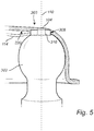
- Fig. 5 illustrates a side-view of the trailer coupling 303 coupled to the tow ball 302.
- the press element 308 receives the tow ball 302 and presses on the pressure sensor 104 located between the bottom surface of the cavity 306 and the press element 308.
- the pressure sensor 104 is electrically connected with a control unit (not shown) via wires 114.
- the wires 114 may be arranged through a duct or hole or arranged in a protective casing and is here shown for illustrative purposes.
- the wires 114 may also be adapted to provide electrical power to the pressure sensor 304.
- the wires 114 may be connected to the vehicle through the electrical connections for providing power to and control of lights (e.g. brake lights, directional lights, parking light, etc.) on the trailer as is well known to the skilled person.
- lights e.g. brake lights, directional lights, parking light, etc.
- a fastening element may be configured to maintain the press element 108 in the cavity 106 when the trailer coupling is disengaged from the tow ball 102.
- the press element 308 may include a magnetic component, whereby the press element 308 is maintained in the cavity 306 by magnetic attraction between the press element 308 and a material in the cavity 306.
- the press element 308 itself may be made from a magnetic material.
- the fastening solution for the press element 308 arranged in the cavity 306 in the trailer coupling is analogous to the one described with reference to fig. 2 , except that the cavity is in the trailer coupling instead of in the tow ball.
- another possible fastening element includes at least one screw or bolt arranged through the press element 308 and fastenable in the cavity 306, wherein the screw or bolt is arranged such that a displacement of the press element is allowed along the axial axis 110.
- This fastening element solution is analogous to the one described with reference to fig. 3 , except that the cavity is in the trailer coupling instead of in the tow ball.
- Fig. 6 conceptually illustrates a trailer coupling 303 comprising a sensor arrangement 300, wherein the cavity 306 (see also fig. 4 ) is arranged in the trailer coupling 303 and the press element 308 is arranged to press on the pressure sensor 104 when the trailer coupling is engaged with a tow ball.
- the trailer coupling 303 comprises a handle 330 which may be lifted for opening the engagement mechanics 332 to allow a tow ball to enter the coupling space 334.
- the connection bar 335 pushes downwards such that the engagement mechanics 332 rotates counter-clockwise about pivot axis 340 and thereby opens the coupling space 334 for the tow ball.
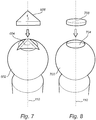
- press elements 308 and 108 are selected for exemplary purposes and may be replaced by any other shape as long as the press element is rotationally locked in the cavity.
- a press element 608 may have a polygonal shape, here exemplified by a triangular press element 608.
- the cross-section of the press element 608 may be triangular or polygonal in a plane perpendicular to the longitudinal axis about which rotational torque is exerted to the press element 608.
- the cavity 604 of the tow ball 602 has the same triangular, or polygonal, shape.
- a press element 708 may have an oval or elliptical shape.
- the cross-section of the press element 708 may be oval or elliptical in a plane perpendicular to the longitudinal axis 110 about which rotational torque is exerted to the press element 708.
- the cavity 704 of the tow ball 702 has the same oval or elliptical shape.
- Fig. 9 is a block diagram that illustrates that a pressure sensor 802 may be configured to transmit a signal 803 indicative of a measured pressure to a vehicle electric control unit 804.
- Connecting the pressure sensor to the vehicle electric control unit provides for real-time monitoring of the nose load for a user.
- the vehicle electric control unit 804 may transmit a signal indicative of the measured pressure to a portable device 806 via wireless transmission. In this way, a user may monitor the nose load with a portable device, thereby not having to enter the vehicle in order to receive information about the nose load.
- the communication between the pressure sensor and the vehicle control unit may be hardwired in the case of having the sensor in the tow ball, or may use other known electrical connection techniques or networks known in the art, and may go though the electrical connection usually used for connecting the trailer lights to the vehicle.
- the vehicle control unit may communicate via CAN-buses Wireless communication may go via a suitable type of communication technology such as e.g. 3G, 4G, 5G, Wi-Fi, Bluetooth, etc.
- the control unit may include a microprocessor, microcontroller, programmable digital signal processor or another programmable device, as well as be embedded into the vehicle/power train control logic/hardware.
- the control unit may also, or instead, include an application-specific integrated circuit, a programmable gate array or programmable array logic, a programmable logic device, or a digital signal processor.
- the processor may further include computer executable code that controls operation of the programmable device.
- the control unit may comprise modules in either hardware or software, or partially in hardware or software and communicate using known transmission buses such as CAN-bus and/or wireless communication capabilities.
Landscapes
- Engineering & Computer Science (AREA)
- Transportation (AREA)
- Mechanical Engineering (AREA)
- Physics & Mathematics (AREA)
- General Physics & Mathematics (AREA)
- Chemical & Material Sciences (AREA)
- Analytical Chemistry (AREA)
- Combustion & Propulsion (AREA)
- Force Measurement Appropriate To Specific Purposes (AREA)
- Measuring Fluid Pressure (AREA)
Abstract
Description
- The present disclosure relates to a sensor arrangement for measuring the pressure on a tow ball of a vehicle caused by a trailer coupling. The present disclosure also relates to a tow hook and a trailer coupling comprising such a sensor arrangement, and to a vehicle and a trailer comprising such a sensor arrangement.
- A typical arrangement for securely coupling a vehicle to a trailer is the tow bar ball coupling. In such arrangements a tow bar is typically attached to a rear part of the vehicle chassis and often comprises a tow ball and a tow bar neck linking the tow ball to the attachment point with the vehicle chassis. The tow ball is adapted to receive a mating coupling attached to the trailer for firmly connecting the trailer to the vehicle.
- The maximum load weight for a trailer is regulated by industry standards and legislation. The load weight on the trailer directly influences the vertical force on the tow ball, and therefore also a vertical load acting in the vehicle rear part, where the tow neck is attached. The load on the tow ball is often referred to as the nose load on the trailer.
- The nose load directly affects the vehicle-trailer driving stability. Too high nose load may lead to loss in driving stability and difficulties in controlling the towing vehicle. On the other hand, too little nose load may in worst cases lead to separation of the trailer from the tow bar ball, or at least to reduced stability of the trailer.
- Several systems for monitoring the nose load have previously been suggested. However, a common problem is that the high loads may damage the system components, such as the load sensor itself.
- Accordingly, there is a need for improved sensor arrangements for measuring a nose load that better protects the system components.
- The disclosed subject matter generally relates to a sensor arrangement for measuring the pressure on a tow ball of a vehicle caused by a trailer coupling.
- The proposed sensor arrangement comprises a pressure sensor which is protected from rotation torques between the tow ball and the trailer coupling.
- When a vehicle tows a trailer and turns, the tow ball and the trailer coupling inevitably rotates with respect to each other. This causes a rotational torque at the interface between wear surfaces of the tow ball and the trailer coupling.
- In order to prevent the pressure sensor from being exposed to the rotation torques present between the tow ball and trailer coupling the inventors realised to include a press element adapted to press in an axial direction on the pressure sensor but which cannot rotate with respect to the pressure sensor.
- The inventors realized to arrange the pressure sensor in a cavity in either the trailer coupling or in the tow ball. The pressure sensor is adapted to measure the pressure applied by the trailer coupling on the tow ball.
- The press element is arranged in the cavity and is adapted to press on the pressure sensor in an axial direction when the trailer coupling applies pressure on the tow ball. The inventors realized to shape the press element and the cavity in such a way that the press element is prevented from rotating in the cavity.
- Thus, the shape, e.g. cross-section, of the cavity may at least partly match that of the press element. The shapes, e.g. cross-sections, of the cavity and the press element are non-circular, such that the press element is rotationally locked in the cavity.
Preferably, the press element is maintained in the cavity when the trailer coupling is disengaged from the tow ball. In this way, the press element is not lost when the trailer coupling is disengaged from the tow ball. For example, the press element may include magnetic component, whereby the press element is maintained in the cavity by magnetic attraction between the press element and a material in the cavity. - There is further provided, in the present disclosure, a trailer coupling comprising a sensor arrangement. In this case, the cavity is arranged in the trailer coupling and the press element is arranged to press on the sensor when the trailer coupling is engaged with a tow ball.
- The trailer coupling may be comprised in a trailer.
- Furthermore, the present disclosure also relates to a towing hook for a vehicle comprising a tow ball adapted to be engaged with a trailer coupling, and a sensor arrangement. In this case, the cavity is arranged in the tow ball and the press element is arranged to press on the sensor when the tow ball is engaged with a trailer coupling.
- Such a towing hook may be comprised in a vehicle.
- Further features of, and advantages with, the present invention will become apparent when studying the appended claims and the following description. The skilled person realize that different features of the present invention may be combined to create embodiments other than those described in the following, without departing from the scope of the present invention.
- These and other aspects of the present invention will now be described in more detail, with reference to the appended drawings showing example embodiments of the invention, wherein:
-
FIG. 1 is a perspective view of a sensor arrangement arranged in a towing hook according to embodiments of the present disclosure; -
FIG. 2 is a partly cut cross-sectional view of a sensor arrangement arranged in a towing hook according to embodiments of the present disclosure; -
FIG. 3 is a partial cross-section of a sensor arrangement arranged in a tow ball according to embodiments of the present disclosure; -
FIG. 4 is a conceptual perspective view of a sensor arrangement arranged in a trailer coupling according to embodiments of the present disclosure; -
FIG. 5 illustrates a side-view of a trailer coupling coupled to a tow ball; -
FIG. 6 conceptually illustrates a trailer coupling comprising a sensor arrangement according to embodiments of the present disclosure; -
FIG. 7 conceptually illustrates an example press element and cavity according to embodiments of the present disclosure; -
FIG. 8 conceptually illustrates an example press element and cavity according to embodiments of the present disclosure; and -
FIG. 9 is a block diagram of apressure sensor 802 connected to a vehicle electric control unit according to embodiments of the present disclosure. - In the present detailed description, various embodiments of a sensing arrangement according to the present invention are described. However, this invention may be embodied in many different forms and should not be construed as limited to the embodiments set forth herein; rather, these embodiments are provided for thoroughness and completeness, and to fully convey the scope of the invention to the skilled person. Like reference characters refer to like elements throughout.
-
Fig. 1 is a perspective view of asensor arrangement 100 for measuring the pressure on atow ball 102 of a vehicle caused by a trailer coupling andFig. 2 illustrates thesensor arrangement 100 in a partly cut cross-sectional view or the tow bar. Thesensor arrangement 100 comprises apressure sensor 104 arranged in acavity 106 in thetow ball 102 and is adapted to measure the pressure applied by the trailer coupling on thetow ball 102. Furthermore, apress element 108 is arrangable in thecavity 106 and is adapted to press on thepressure sensor 102 in anaxial direction 109 when the trailer coupling applies pressure on thetow ball 102. Thepress element 108 and thecavity 106 are shaped in such a way that thepress element 108 is prevented from rotating in thecavity 102. - The inventors realized that a simple yet reliable way to protect the pressure sensor is to arrange it in a cavity in the tow ball, whereby a press element is arranged to press on the pressure sensor when the tow ball is coupled with a trailer coupling. Advantageously, the press element and the cavity are cooperatively configured such that the press element is not allowed to rotate in the cavity.
- In use, a trailer coupling applies pressure on the press element. In response, since the press element in that situation is located between the pressure sensor and the trailer coupling, the press element transfers the pressure from the trailer coupling to the pressure sensor.
- The pressure that the
pressure sensor 104 is configured to measure is the axial pressure applied by the trailer coupling on thetow ball 102. The axial direction, indicated by thearrow 109, is along anaxis 110 substantially along thetow bar 112 longitudinal axis. Theaxial direction 109 is often substantially vertical when the trailer coupling is coupled with thetow ball 102. - In order to read out a pressure measurement, the
pressure sensor 104 is electrically connectable with a control unit (not shown) viawires 114 here shown to be lead through a duct in thetow ball 102 andtow bar 112. However, the connections may be made in other ways than the depicted example embodiment. Thewires 114 may also be adapted to provide electrical power to thepressure sensor 104. - The pressure sensor may be of various types known per se in the art, for example, the sensor may be a piezo-electric sensor such as a piezo-electric strain gauge sensor, or a capacitive pressure sensor.
- The
pressure sensor 104 may be attached to the bottom of thecavity 106, whereby thepressure sensor 104 is interleaved between the bottom of the cavity and thepress element 108 when the press element is correctly installed in thecavity 106. - The shape of the
press element 108 should be such that thepress element 108 may not rotate in thecavity 106. For example, the press element and the cavity may be non-circular such that thepress element 108 is rotationally locked in thecavity 106. - In
fig. 1 , thepress element 108 comprises aradial protrusion 116 that fits into a correspondingradial shape 118 of thecavity 106 to thereby rotationally lock thepress element 108. Theradial protrusion 116 extends in a radial direction perpendicular to theaxis 110 along which the axial force from the trailer coupling is applied. In a cross-section in the plane of the radial direction, thepress element 108 may have a "key-hole" shape cross-section. At the same time, thecavity 104 has a similar "key-hole" shaped cross-section. - When the
press element 108 is correctly placed in thecavity 106 to be rotationally locked, it is prevented from rotating about theaxial axis 110. It is about theaxis 110 that most of the rotation torque at the connection between thetow ball 102 and the trailer coupling occurs. Thus, by preventing the rotation of the press element about theaxis 110, the pressure sensor may be protected from the rotation torque while at the same time being able to measure the axial force. - According to embodiments, the
press element 108 may be coated with a hard low friction material on awear surface 117 located on a side of thepress element 108 opposite the side facing thepressure sensor 104. In other words, thewear surface 117 which is in contact with the trailer coupling when thetow ball 102 is coupled to the trailer coupling is coated with a hard low friction material in order to reduce wear on thepress element 108. Such hard low friction material include for instance titanium or composite ceramic nickel alloy composition or likewise products that are available on the market and known per se. The hard hard low friction material on the wear surface provides increased wear strength to thewear surface 117 which is exposed to the rotational torques when in use. - In order to prevent the
press element 108 from falling out of the cavity when the trailer coupling is not coupled to thetow ball 102, a fastening means is desirable for maintaining thepress element 108 in thecavity 106 when the trailer coupling is disengaged from thetow ball 102. - According to one embodiment, the press element may include a magnetic component, whereby the
press element 108 is maintained in thecavity 106 by magnetic attraction between thepress element 108 and a material in thecavity 106. In other words, a magnet (not shown) may be attached to thepress element 108, or integrated with thepress element 108. - In one preferred embodiment, the
press element 108 itself is made from a magnetic material such as ferromagnetic steel compounded of iron (magnetite or lodestone), cobalt and nickel. In such case, thewear surface 117 is coated with non-magnetic hard low friction material such as the ones mentioned above such that the press element is not drawn out from the cavity by thetow bar 102. - The magnetic forces between the
magnetic press element 108 and the material of the cavity are such that thepress element 108 may be removed from the cavity with exercising excessive force, e.g. a removal by hand is preferably possible. - In embodiments, a fastening element is configured to maintain the press element in the cavity when the trailer coupling is disengaged from the tow ball. Thus, a separate element may be used for ensuring that the press element stays in the cavity in cases where a magnetic solution is not preferred.
-
Fig. 3 illustrates one possible fastening element according to embodiments of the present disclosure. Here, the fastening element includes at least one screw or bolt 120 arranged through thepress element 122 and fastenable in thecavity 106, wherein the screw or bolt 120 is arranged such that adisplacement 124 of thepress element 122 is allowed along theaxis 110. - The
bolt 120 is arranged through through-holes of thepress element 122 and tightened in threadedholes 126 in thecavity 106. However, the length of thebolts 120 are such that thepress element 122 may move asmall displacement distance 124 before theheads 128 of the bolts prevents thepress element 122 from falling out of thecavity 106. In this way, it is ensured that the measured pressure originates from the trailer coupling pressing on thetow ball 102, and not from thebolts 120 pressing thepress element 122 towards thepressure sensor 104. - When the bolts are tightened to maintain the
press element 122 in place, theheads 128 of thebolts 120 are located in arespective cavity 130 of thepress element 122 such that theheads 128 are below thewear surface 117 of thepress element 122, i.e. thebolts 120 are sunk below thewear surface 117 of thepress element 122. This prevents thebolts 120 from obstructing the coupling between thetow ball 102 and the trailer coupling, and prevents thebolts 120 from being subjected to the load from the trailer coupling. Thecavity 130 and the holes through thepress element 122 may be so-called counter-bored holes. - In accordance with embodiments of the invention, and as is shown in
figs. 1 and2 , there is also provided atowing hook 200 for a vehicle comprising atow ball 102 adapted to be engaged with a trailer coupling and asensor arrangement 100, wherein thecavity 106 is arranged in thetow ball 102 and thepress element 106 is arranged to press on thepressure sensor 104 when the tow ball is engaged with a trailer coupling. - According to embodiments, the
cavity 106 is a milled cavity in atop surface 202 of thetow ball 102. Accordingly, the cavity is advantageously made by milling into thetow ball 102. Milling provides for a reliable method for forming the cavity with sufficient tolerance. - Furthermore, the
tow ball 102 and thetow bar 112 comprises anaxial duct 204 through which thepressure sensor 104 is connected to a vehicle electric control unit by means of wiring 114 arranged in theaxial duct 204, seefig. 1 . -
Fig. 4 conceptually illustrates asensor arrangement 300 for measuring the pressure on atow ball 302 of a vehicle caused by atrailer coupling 303, thesensor arrangement 300 comprising apressure sensor 104 arranged in a cavity 306 in thetrailer coupling 303 and adapted to measure the pressure applied by thetrailer coupling 303 on thetow ball 302. Furthermore, apress element 308 is arrangable in the cavity 306 and adapted to press on thepressure sensor 104 in an axial direction when thetrailer coupling 303 applies pressure on thetow ball 302. Thepress element 308 and the cavity 306 are shaped in such a way that thepress element 308 is prevented from rotating in the cavity 306. - Accordingly, the inventors have realized that the pressure sensor and the pressure plate may be placed either in the tow ball as shown in
fig. 1 and2 or in the trailer coupling as will now be described with reference tofigs. 3-5 . - Thus, the inventors realized that a simple yet reliable way to protect the pressure sensor is to arrange it in a cavity in the trailer coupling, whereby a press element is arranged to press on the pressure sensor when the tow ball is coupled with a trailer coupling. Advantageously, the press element and the cavity are cooperatively configured such that the press element is not allowed to rotate in the cavity.
- The pressure that the
pressure sensor 104 is configured to measure is the axial pressure applied by thetrailer coupling 303 on thetow ball 302. The axial direction, indicated by thearrow 309, is along anaxis 110 substantially along thetow bar 112 longitudinal axis. Theaxial direction 109 is often substantially vertical when thetrailer coupling 303 is coupled with thetow ball 102. - The
pressure sensor 104 may be attached to the bottom of the cavity 306, whereby thepressure sensor 104 is interleaved between the bottom of the cavity 306 and thepress element 308 when thepress element 308 is correctly installed in the cavity 306. - The shape of the
press element 308 should be such that thepress element 308 may not rotate in the cavity 306. For example, the press element and the cavity may be non-circular such that thepress element 308 is rotationally locked in the cavity 306. - In
fig. 4 , thepress element 308 comprisesradial protrusions 316 that fit into a correspondingradial shape 318 of the cavity 306 to thereby rotationally lock thepress element 308. Theradial protrusions 316 extend in a radial direction substantially perpendicular to theaxial axis 110. - When the
press element 308 is correctly placed in the cavity 306 to be rotationally locked, it is prevented from rotating about theaxial axis 110 about which axis most of the rotation torque at the connection between thetow ball 102 and the trailer coupling occurs, as was discussed above in relation tofigs 1 and2 . - Similar to what was described with reference to
fig. 1 , thepress element 308 may be coated with a hard low friction material on awear surface 317 located on a side of thepress element 308 opposite the side facing thepressure sensor 104. In other words, thewear surface 117 which is in contact with thetow ball 102 when thetrailer coupling 303 is coupled to thetow ball 102 is coated with a hard low friction material in order to reduce wear on thepress element 308. - The cavity 306 may be a milled cavity formed in an
inner surface 320 of thetrailer coupling 303 at the interface between thetrailer coupling 303 and thetow ball 302 when engaged with each other. -
Fig. 5 illustrates a side-view of thetrailer coupling 303 coupled to thetow ball 302. Thepress element 308 receives thetow ball 302 and presses on thepressure sensor 104 located between the bottom surface of the cavity 306 and thepress element 308. - In order to read out a pressure measurement from the
pressure sensor 104, thepressure sensor 104 is electrically connected with a control unit (not shown) viawires 114. Thewires 114 may be arranged through a duct or hole or arranged in a protective casing and is here shown for illustrative purposes. Thewires 114 may also be adapted to provide electrical power to the pressure sensor 304. Thewires 114 may be connected to the vehicle through the electrical connections for providing power to and control of lights (e.g. brake lights, directional lights, parking light, etc.) on the trailer as is well known to the skilled person. - Similar to when the press element is arranged in the tow ball, in order to prevent the
press element 108 from falling out of the cavity 306 when the trailer coupling is not coupled to thetow ball 102, a fastening element may be configured to maintain thepress element 108 in thecavity 106 when the trailer coupling is disengaged from thetow ball 102. - As was the case with the
press element 108 described with reference tofigs 1-2 , thepress element 308 may include a magnetic component, whereby thepress element 308 is maintained in the cavity 306 by magnetic attraction between thepress element 308 and a material in the cavity 306. Preferable, thepress element 308 itself may be made from a magnetic material. Thus, the fastening solution for thepress element 308 arranged in the cavity 306 in the trailer coupling is analogous to the one described with reference tofig. 2 , except that the cavity is in the trailer coupling instead of in the tow ball. - Additionally, another possible fastening element according to embodiments of the present disclosure includes at least one screw or bolt arranged through the
press element 308 and fastenable in the cavity 306, wherein the screw or bolt is arranged such that a displacement of the press element is allowed along theaxial axis 110. This fastening element solution is analogous to the one described with reference tofig. 3 , except that the cavity is in the trailer coupling instead of in the tow ball. -
Fig. 6 conceptually illustrates atrailer coupling 303 comprising asensor arrangement 300, wherein the cavity 306 (see alsofig. 4 ) is arranged in thetrailer coupling 303 and thepress element 308 is arranged to press on thepressure sensor 104 when the trailer coupling is engaged with a tow ball. - As is often the case, and for the sake of completeness, the
trailer coupling 303 comprises ahandle 330 which may be lifted for opening theengagement mechanics 332 to allow a tow ball to enter thecoupling space 334. When thehandle 330 is lifted, theconnection bar 335 pushes downwards such that theengagement mechanics 332 rotates counter-clockwise aboutpivot axis 340 and thereby opens thecoupling space 334 for the tow ball. This type of coupling solution for engaging a tow bar with a trailer coupling is shown for example purposes and many different solutions are known to the skilled person and are within the scope of the appended claims. - The particular shapes of the
press elements - For example, as illustrated in
fig. 7 apress element 608 may have a polygonal shape, here exemplified by atriangular press element 608. Thus, the cross-section of thepress element 608 may be triangular or polygonal in a plane perpendicular to the longitudinal axis about which rotational torque is exerted to thepress element 608. In this case, thecavity 604 of thetow ball 602 has the same triangular, or polygonal, shape. - Furthermore, as illustrated in
fig. 8 apress element 708 may have an oval or elliptical shape. Thus, the cross-section of thepress element 708 may be oval or elliptical in a plane perpendicular to thelongitudinal axis 110 about which rotational torque is exerted to thepress element 708. In this case, thecavity 704 of thetow ball 702 has the same oval or elliptical shape. -
Fig. 9 is a block diagram that illustrates that apressure sensor 802 may be configured to transmit asignal 803 indicative of a measured pressure to a vehicleelectric control unit 804. - Connecting the pressure sensor to the vehicle electric control unit provides for real-time monitoring of the nose load for a user. In addition, the vehicle
electric control unit 804 may transmit a signal indicative of the measured pressure to aportable device 806 via wireless transmission. In this way, a user may monitor the nose load with a portable device, thereby not having to enter the vehicle in order to receive information about the nose load. - There is further provided a vehicle comprising the towing hook according to any one of the herein disclosed embodiments.
- The communication between the pressure sensor and the vehicle control unit may be hardwired in the case of having the sensor in the tow ball, or may use other known electrical connection techniques or networks known in the art, and may go though the electrical connection usually used for connecting the trailer lights to the vehicle. The vehicle control unit may communicate via CAN-buses Wireless communication may go via a suitable type of communication technology such as e.g. 3G, 4G, 5G, Wi-Fi, Bluetooth, etc.
- The control unit may include a microprocessor, microcontroller, programmable digital signal processor or another programmable device, as well as be embedded into the vehicle/power train control logic/hardware. The control unit may also, or instead, include an application-specific integrated circuit, a programmable gate array or programmable array logic, a programmable logic device, or a digital signal processor. Where the control unit includes a programmable device such as the microprocessor, microcontroller or programmable digital signal processor mentioned above, the processor may further include computer executable code that controls operation of the programmable device. The control unit may comprise modules in either hardware or software, or partially in hardware or software and communicate using known transmission buses such as CAN-bus and/or wireless communication capabilities.
- The person skilled in the art realizes that the present invention by no means is limited to the preferred embodiments described above. On the contrary, many modifications and variations are possible within the scope of the appended claims.
- In the claims, the word "comprising" does not exclude other elements or steps, and the indefinite article "a" or "an" does not exclude a plurality. A single processor or other unit may fulfill the functions of several items recited in the claims. The mere fact that certain measures are recited in mutually different dependent claims does not indicate that a combination of these measured cannot be used to advantage. Any reference signs in the claims should not be construed as limiting the scope.
- Various examples have been described. These and other examples are within the scope of the following claims.
Claims (15)
- A sensor arrangement for measuring the pressure on a tow ball of a vehicle caused by a trailer coupling, the sensor arrangement comprising:a pressure sensor arranged in a cavity in either the trailer coupling or a cavity in the tow ball and adapted to measure the pressure applied by the trailer coupling on the tow ball, anda press element arrangable in the cavity and adapted to press on the pressure sensor in an axial direction when the trailer coupling applies pressure on the tow ball, wherein the press element and the cavity are shaped in such a way that the press element is prevented from rotating in the cavity.
- The sensor arrangement according to claim 1, wherein the press element comprises a radial protrusion that fits into a corresponding radial shape of the cavity to thereby rotationally lock the press element.
- The sensor arrangement according to claim 1, wherein the press element and the cavity are non-circular such that the press element is rotationally locked in the cavity.
- The sensor arrangement according to any one of the preceding claims, wherein the press element includes a magnetic component, whereby the press element is maintained in the cavity by magnetic attraction between the press element and a material in the cavity.
- The sensor arrangement according to any one of the preceding claims, comprising a fastening element configured to maintain the press element in the cavity when the trailer coupling is disengaged from the tow ball.
- The sensor arrangement according to claim 5, wherein the fastening element is at least one screw or bolt arranged through the press element and fastenable in the cavity, wherein the screw or bolt is arranged such that a displacement of the press element is allowed along the axis of the axial direction.
- The sensor arrangement according to any one of the preceding claims, wherein the pressure sensor configured to transmit a signal indicative of a measured pressure to a vehicle electric control unit.
- The sensor arrangement according to any one of the preceding claims, wherein the press element is coated with a hard low friction material on a wear surface located on a side of the press element opposite the side facing the pressure sensor.
- The sensor arrangement according to any one of the preceding claims, wherein the pressure sensor is attached to the bottom of the cavity.
- A trailer coupling comprising a sensor arrangement according to any one of the preceding claims, wherein the cavity is arranged in the trailer coupling and the press element is arranged to press on the sensor when the trailer coupling is engaged with a tow ball.
- The trailer coupling according to claim 10, wherein the cavity is a milled cavity formed in an inner surface of the trailer coupling at the interface between the trailer coupling and a tow ball when engaged with each other.
- A trailer comprising the trailer coupling according to any one of claims 10 or 11.
- A towing hook for a vehicle comprising a tow ball adapted to be engaged with a trailer coupling and a sensor arrangement according to any one of claims 1 to 9, wherein the cavity is arranged in the tow ball and the press element is arranged to press on the sensor when the tow ball is engaged with a trailer coupling.
- The towing hook according to claim 13, wherein the cavity is a milled cavity on a top surface of the tow ball.
- The towing hook according to any on of claims 13 or 14, wherein the tow ball and the tow bar comprises an axial duct through which the pressure sensor is connected to a vehicle electric control unit by means of wiring arranged in the axial duct.
Priority Applications (1)
| Application Number | Priority Date | Filing Date | Title |
|---|---|---|---|
| EP19168152.7A EP3722116B1 (en) | 2019-04-09 | 2019-04-09 | A sensor arrangement for measuring trailer nose load |
Applications Claiming Priority (1)
| Application Number | Priority Date | Filing Date | Title |
|---|---|---|---|
| EP19168152.7A EP3722116B1 (en) | 2019-04-09 | 2019-04-09 | A sensor arrangement for measuring trailer nose load |
Publications (2)
| Publication Number | Publication Date |
|---|---|
| EP3722116A1 true EP3722116A1 (en) | 2020-10-14 |
| EP3722116B1 EP3722116B1 (en) | 2023-08-02 |
Family
ID=66102963
Family Applications (1)
| Application Number | Title | Priority Date | Filing Date |
|---|---|---|---|
| EP19168152.7A Active EP3722116B1 (en) | 2019-04-09 | 2019-04-09 | A sensor arrangement for measuring trailer nose load |
Country Status (1)
| Country | Link |
|---|---|
| EP (1) | EP3722116B1 (en) |
Cited By (1)
| Publication number | Priority date | Publication date | Assignee | Title |
|---|---|---|---|---|
| WO2024243616A1 (en) * | 2023-05-26 | 2024-12-05 | Redarc Technologies Pty Ltd | A system for a tow vehicle-trailer combination |
Citations (8)
| Publication number | Priority date | Publication date | Assignee | Title |
|---|---|---|---|---|
| US4319766A (en) * | 1980-06-25 | 1982-03-16 | General Motors Corporation | Vehicle trailer hitch |
| GB2288776A (en) * | 1994-04-21 | 1995-11-01 | Timothy Guy Letchford | Stabilising tow ball with load indication |
| US6053521A (en) * | 1998-04-16 | 2000-04-25 | Schertler; Stephen James | Load sensing trailer ball-hitch drawbar |
| WO2002002360A1 (en) * | 2000-07-03 | 2002-01-10 | Martin Hansen | Coupling device for mounting between the drawhook on a car or another type of tractor and the eye bolt on a trailer |
| US6722684B1 (en) * | 2001-04-09 | 2004-04-20 | Mcallister Kevin L. | Trailer hitch and associated methods |
| US20060290102A1 (en) * | 2005-06-22 | 2006-12-28 | Vanbuskirk William J Jr | Weight Sensing Trailer Ball |
| DE202007008391U1 (en) * | 2007-06-12 | 2007-08-16 | Weber, Christian | Trailer e.g. caravan, coupling for e.g. passenger car, has measuring device determining support load weight of trailer, where measuring device is arranged above ball socket of trailer towing bar |
| DE102011076392A1 (en) * | 2011-05-24 | 2012-11-29 | Robert Bosch Gmbh | Arrangement for connecting a towing vehicle with a trailer |
-
2019
- 2019-04-09 EP EP19168152.7A patent/EP3722116B1/en active Active
Patent Citations (8)
| Publication number | Priority date | Publication date | Assignee | Title |
|---|---|---|---|---|
| US4319766A (en) * | 1980-06-25 | 1982-03-16 | General Motors Corporation | Vehicle trailer hitch |
| GB2288776A (en) * | 1994-04-21 | 1995-11-01 | Timothy Guy Letchford | Stabilising tow ball with load indication |
| US6053521A (en) * | 1998-04-16 | 2000-04-25 | Schertler; Stephen James | Load sensing trailer ball-hitch drawbar |
| WO2002002360A1 (en) * | 2000-07-03 | 2002-01-10 | Martin Hansen | Coupling device for mounting between the drawhook on a car or another type of tractor and the eye bolt on a trailer |
| US6722684B1 (en) * | 2001-04-09 | 2004-04-20 | Mcallister Kevin L. | Trailer hitch and associated methods |
| US20060290102A1 (en) * | 2005-06-22 | 2006-12-28 | Vanbuskirk William J Jr | Weight Sensing Trailer Ball |
| DE202007008391U1 (en) * | 2007-06-12 | 2007-08-16 | Weber, Christian | Trailer e.g. caravan, coupling for e.g. passenger car, has measuring device determining support load weight of trailer, where measuring device is arranged above ball socket of trailer towing bar |
| DE102011076392A1 (en) * | 2011-05-24 | 2012-11-29 | Robert Bosch Gmbh | Arrangement for connecting a towing vehicle with a trailer |
Cited By (1)
| Publication number | Priority date | Publication date | Assignee | Title |
|---|---|---|---|---|
| WO2024243616A1 (en) * | 2023-05-26 | 2024-12-05 | Redarc Technologies Pty Ltd | A system for a tow vehicle-trailer combination |
Also Published As
| Publication number | Publication date |
|---|---|
| EP3722116B1 (en) | 2023-08-02 |
Similar Documents
| Publication | Publication Date | Title |
|---|---|---|
| EP3822505B1 (en) | Brake continuous wear sensor (cws) located in guide sleeve | |
| US6053521A (en) | Load sensing trailer ball-hitch drawbar | |
| US9945437B2 (en) | Systems and methods for detecting wear of brake pads | |
| US20180306256A1 (en) | Multiple function brake caliper guide pin | |
| EP0302437B1 (en) | Force measuring device | |
| US9302889B2 (en) | Hoisting device and system and method for using the same | |
| US20160146279A1 (en) | Brake Pad Wear Monitoring System | |
| US6722684B1 (en) | Trailer hitch and associated methods | |
| CA1245993A (en) | Resistive ceramic bushings for brake lining wear sensor | |
| EP3722116B1 (en) | A sensor arrangement for measuring trailer nose load | |
| MXPA03006493A (en) | Mecchanism with load sensor for operating a brake. | |
| US6696937B1 (en) | Wireless brake condition monitor | |
| CN111521318B (en) | Brake torque sensor | |
| JP2010235113A (en) | Advanced antiskid mechanism braking and driving force control apparatus and method | |
| US6144307A (en) | Monitor and/or overload means | |
| US11915530B2 (en) | Wheel end monitoring apparatus, fastener, and method | |
| DE102018116233A1 (en) | POSITION DETECTION SYSTEM FOR A BRAKING SYSTEM | |
| CA3040620A1 (en) | Threaded fastener load monitoring | |
| TWI664356B (en) | Power supply and signal transmitting device for sensing bolt and sensing bolt device | |
| US5441293A (en) | Draw-bar couplings for vehicles | |
| CN210106461U (en) | Drum brake wear alarm system and mobile crane | |
| EP1399681B1 (en) | Brake lining wear system | |
| CN108759765A (en) | The roughness measurement device and brake disc planeness detection system of brake disc | |
| US7021179B2 (en) | Pressure-operated power screwdriver having a measuring section | |
| CN116601406A (en) | Pad retention assemblies, caliper assemblies, disc brakes and disc brake monitoring systems |
Legal Events
| Date | Code | Title | Description |
|---|---|---|---|
| PUAI | Public reference made under article 153(3) epc to a published international application that has entered the european phase |
Free format text: ORIGINAL CODE: 0009012 |
|
| STAA | Information on the status of an ep patent application or granted ep patent |
Free format text: STATUS: THE APPLICATION HAS BEEN PUBLISHED |
|
| AK | Designated contracting states |
Kind code of ref document: A1 Designated state(s): AL AT BE BG CH CY CZ DE DK EE ES FI FR GB GR HR HU IE IS IT LI LT LU LV MC MK MT NL NO PL PT RO RS SE SI SK SM TR |
|
| AX | Request for extension of the european patent |
Extension state: BA ME |
|
| STAA | Information on the status of an ep patent application or granted ep patent |
Free format text: STATUS: REQUEST FOR EXAMINATION WAS MADE |
|
| 17P | Request for examination filed |
Effective date: 20210414 |
|
| RBV | Designated contracting states (corrected) |
Designated state(s): AL AT BE BG CH CY CZ DE DK EE ES FI FR GB GR HR HU IE IS IT LI LT LU LV MC MK MT NL NO PL PT RO RS SE SI SK SM TR |
|
| STAA | Information on the status of an ep patent application or granted ep patent |
Free format text: STATUS: EXAMINATION IS IN PROGRESS |
|
| 17Q | First examination report despatched |
Effective date: 20211014 |
|
| GRAP | Despatch of communication of intention to grant a patent |
Free format text: ORIGINAL CODE: EPIDOSNIGR1 |
|
| STAA | Information on the status of an ep patent application or granted ep patent |
Free format text: STATUS: GRANT OF PATENT IS INTENDED |
|
| INTG | Intention to grant announced |
Effective date: 20230421 |
|
| GRAS | Grant fee paid |
Free format text: ORIGINAL CODE: EPIDOSNIGR3 |
|
| GRAA | (expected) grant |
Free format text: ORIGINAL CODE: 0009210 |
|
| STAA | Information on the status of an ep patent application or granted ep patent |
Free format text: STATUS: THE PATENT HAS BEEN GRANTED |
|
| AK | Designated contracting states |
Kind code of ref document: B1 Designated state(s): AL AT BE BG CH CY CZ DE DK EE ES FI FR GB GR HR HU IE IS IT LI LT LU LV MC MK MT NL NO PL PT RO RS SE SI SK SM TR |
|
| REG | Reference to a national code |
Ref country code: GB Ref legal event code: FG4D |
|
| REG | Reference to a national code |
Ref country code: CH Ref legal event code: EP |
|
| P01 | Opt-out of the competence of the unified patent court (upc) registered |
Effective date: 20230710 |
|
| REG | Reference to a national code |
Ref country code: DE Ref legal event code: R096 Ref document number: 602019033867 Country of ref document: DE |
|
| REG | Reference to a national code |
Ref country code: IE Ref legal event code: FG4D |
|
| REG | Reference to a national code |
Ref country code: LT Ref legal event code: MG9D |
|
| REG | Reference to a national code |
Ref country code: NL Ref legal event code: MP Effective date: 20230802 |
|
| REG | Reference to a national code |
Ref country code: AT Ref legal event code: MK05 Ref document number: 1594289 Country of ref document: AT Kind code of ref document: T Effective date: 20230802 |
|
| PG25 | Lapsed in a contracting state [announced via postgrant information from national office to epo] |
Ref country code: GR Free format text: LAPSE BECAUSE OF FAILURE TO SUBMIT A TRANSLATION OF THE DESCRIPTION OR TO PAY THE FEE WITHIN THE PRESCRIBED TIME-LIMIT Effective date: 20231103 |
|
| PG25 | Lapsed in a contracting state [announced via postgrant information from national office to epo] |
Ref country code: IS Free format text: LAPSE BECAUSE OF FAILURE TO SUBMIT A TRANSLATION OF THE DESCRIPTION OR TO PAY THE FEE WITHIN THE PRESCRIBED TIME-LIMIT Effective date: 20231202 |
|
| PG25 | Lapsed in a contracting state [announced via postgrant information from national office to epo] |
Ref country code: SE Free format text: LAPSE BECAUSE OF FAILURE TO SUBMIT A TRANSLATION OF THE DESCRIPTION OR TO PAY THE FEE WITHIN THE PRESCRIBED TIME-LIMIT Effective date: 20230802 Ref country code: RS Free format text: LAPSE BECAUSE OF FAILURE TO SUBMIT A TRANSLATION OF THE DESCRIPTION OR TO PAY THE FEE WITHIN THE PRESCRIBED TIME-LIMIT Effective date: 20230802 Ref country code: PT Free format text: LAPSE BECAUSE OF FAILURE TO SUBMIT A TRANSLATION OF THE DESCRIPTION OR TO PAY THE FEE WITHIN THE PRESCRIBED TIME-LIMIT Effective date: 20231204 Ref country code: NO Free format text: LAPSE BECAUSE OF FAILURE TO SUBMIT A TRANSLATION OF THE DESCRIPTION OR TO PAY THE FEE WITHIN THE PRESCRIBED TIME-LIMIT Effective date: 20231102 Ref country code: NL Free format text: LAPSE BECAUSE OF FAILURE TO SUBMIT A TRANSLATION OF THE DESCRIPTION OR TO PAY THE FEE WITHIN THE PRESCRIBED TIME-LIMIT Effective date: 20230802 Ref country code: LV Free format text: LAPSE BECAUSE OF FAILURE TO SUBMIT A TRANSLATION OF THE DESCRIPTION OR TO PAY THE FEE WITHIN THE PRESCRIBED TIME-LIMIT Effective date: 20230802 Ref country code: LT Free format text: LAPSE BECAUSE OF FAILURE TO SUBMIT A TRANSLATION OF THE DESCRIPTION OR TO PAY THE FEE WITHIN THE PRESCRIBED TIME-LIMIT Effective date: 20230802 Ref country code: IS Free format text: LAPSE BECAUSE OF FAILURE TO SUBMIT A TRANSLATION OF THE DESCRIPTION OR TO PAY THE FEE WITHIN THE PRESCRIBED TIME-LIMIT Effective date: 20231202 Ref country code: HR Free format text: LAPSE BECAUSE OF FAILURE TO SUBMIT A TRANSLATION OF THE DESCRIPTION OR TO PAY THE FEE WITHIN THE PRESCRIBED TIME-LIMIT Effective date: 20230802 Ref country code: GR Free format text: LAPSE BECAUSE OF FAILURE TO SUBMIT A TRANSLATION OF THE DESCRIPTION OR TO PAY THE FEE WITHIN THE PRESCRIBED TIME-LIMIT Effective date: 20231103 Ref country code: FI Free format text: LAPSE BECAUSE OF FAILURE TO SUBMIT A TRANSLATION OF THE DESCRIPTION OR TO PAY THE FEE WITHIN THE PRESCRIBED TIME-LIMIT Effective date: 20230802 Ref country code: AT Free format text: LAPSE BECAUSE OF FAILURE TO SUBMIT A TRANSLATION OF THE DESCRIPTION OR TO PAY THE FEE WITHIN THE PRESCRIBED TIME-LIMIT Effective date: 20230802 |
|
| PG25 | Lapsed in a contracting state [announced via postgrant information from national office to epo] |
Ref country code: PL Free format text: LAPSE BECAUSE OF FAILURE TO SUBMIT A TRANSLATION OF THE DESCRIPTION OR TO PAY THE FEE WITHIN THE PRESCRIBED TIME-LIMIT Effective date: 20230802 |
|
| PG25 | Lapsed in a contracting state [announced via postgrant information from national office to epo] |
Ref country code: ES Free format text: LAPSE BECAUSE OF FAILURE TO SUBMIT A TRANSLATION OF THE DESCRIPTION OR TO PAY THE FEE WITHIN THE PRESCRIBED TIME-LIMIT Effective date: 20230802 |
|
| PG25 | Lapsed in a contracting state [announced via postgrant information from national office to epo] |
Ref country code: SM Free format text: LAPSE BECAUSE OF FAILURE TO SUBMIT A TRANSLATION OF THE DESCRIPTION OR TO PAY THE FEE WITHIN THE PRESCRIBED TIME-LIMIT Effective date: 20230802 Ref country code: RO Free format text: LAPSE BECAUSE OF FAILURE TO SUBMIT A TRANSLATION OF THE DESCRIPTION OR TO PAY THE FEE WITHIN THE PRESCRIBED TIME-LIMIT Effective date: 20230802 Ref country code: ES Free format text: LAPSE BECAUSE OF FAILURE TO SUBMIT A TRANSLATION OF THE DESCRIPTION OR TO PAY THE FEE WITHIN THE PRESCRIBED TIME-LIMIT Effective date: 20230802 Ref country code: EE Free format text: LAPSE BECAUSE OF FAILURE TO SUBMIT A TRANSLATION OF THE DESCRIPTION OR TO PAY THE FEE WITHIN THE PRESCRIBED TIME-LIMIT Effective date: 20230802 Ref country code: DK Free format text: LAPSE BECAUSE OF FAILURE TO SUBMIT A TRANSLATION OF THE DESCRIPTION OR TO PAY THE FEE WITHIN THE PRESCRIBED TIME-LIMIT Effective date: 20230802 Ref country code: CZ Free format text: LAPSE BECAUSE OF FAILURE TO SUBMIT A TRANSLATION OF THE DESCRIPTION OR TO PAY THE FEE WITHIN THE PRESCRIBED TIME-LIMIT Effective date: 20230802 Ref country code: SK Free format text: LAPSE BECAUSE OF FAILURE TO SUBMIT A TRANSLATION OF THE DESCRIPTION OR TO PAY THE FEE WITHIN THE PRESCRIBED TIME-LIMIT Effective date: 20230802 |
|
| REG | Reference to a national code |
Ref country code: DE Ref legal event code: R097 Ref document number: 602019033867 Country of ref document: DE |
|
| PG25 | Lapsed in a contracting state [announced via postgrant information from national office to epo] |
Ref country code: IT Free format text: LAPSE BECAUSE OF FAILURE TO SUBMIT A TRANSLATION OF THE DESCRIPTION OR TO PAY THE FEE WITHIN THE PRESCRIBED TIME-LIMIT Effective date: 20230802 |
|
| PLBE | No opposition filed within time limit |
Free format text: ORIGINAL CODE: 0009261 |
|
| STAA | Information on the status of an ep patent application or granted ep patent |
Free format text: STATUS: NO OPPOSITION FILED WITHIN TIME LIMIT |
|
| 26N | No opposition filed |
Effective date: 20240503 |
|
| PG25 | Lapsed in a contracting state [announced via postgrant information from national office to epo] |
Ref country code: SI Free format text: LAPSE BECAUSE OF FAILURE TO SUBMIT A TRANSLATION OF THE DESCRIPTION OR TO PAY THE FEE WITHIN THE PRESCRIBED TIME-LIMIT Effective date: 20230802 |
|
| PG25 | Lapsed in a contracting state [announced via postgrant information from national office to epo] |
Ref country code: BG Free format text: LAPSE BECAUSE OF FAILURE TO SUBMIT A TRANSLATION OF THE DESCRIPTION OR TO PAY THE FEE WITHIN THE PRESCRIBED TIME-LIMIT Effective date: 20230802 |
|
| PG25 | Lapsed in a contracting state [announced via postgrant information from national office to epo] |
Ref country code: MC Free format text: LAPSE BECAUSE OF FAILURE TO SUBMIT A TRANSLATION OF THE DESCRIPTION OR TO PAY THE FEE WITHIN THE PRESCRIBED TIME-LIMIT Effective date: 20230802 |
|
| PG25 | Lapsed in a contracting state [announced via postgrant information from national office to epo] |
Ref country code: MC Free format text: LAPSE BECAUSE OF FAILURE TO SUBMIT A TRANSLATION OF THE DESCRIPTION OR TO PAY THE FEE WITHIN THE PRESCRIBED TIME-LIMIT Effective date: 20230802 Ref country code: BG Free format text: LAPSE BECAUSE OF FAILURE TO SUBMIT A TRANSLATION OF THE DESCRIPTION OR TO PAY THE FEE WITHIN THE PRESCRIBED TIME-LIMIT Effective date: 20230802 |
|
| REG | Reference to a national code |
Ref country code: CH Ref legal event code: PL |
|
| PG25 | Lapsed in a contracting state [announced via postgrant information from national office to epo] |
Ref country code: LU Free format text: LAPSE BECAUSE OF NON-PAYMENT OF DUE FEES Effective date: 20240409 |
|
| REG | Reference to a national code |
Ref country code: BE Ref legal event code: MM Effective date: 20240430 |
|
| PG25 | Lapsed in a contracting state [announced via postgrant information from national office to epo] |
Ref country code: LU Free format text: LAPSE BECAUSE OF NON-PAYMENT OF DUE FEES Effective date: 20240409 |
|
| PG25 | Lapsed in a contracting state [announced via postgrant information from national office to epo] |
Ref country code: BE Free format text: LAPSE BECAUSE OF NON-PAYMENT OF DUE FEES Effective date: 20240430 |
|
| PG25 | Lapsed in a contracting state [announced via postgrant information from national office to epo] |
Ref country code: BE Free format text: LAPSE BECAUSE OF NON-PAYMENT OF DUE FEES Effective date: 20240430 Ref country code: CH Free format text: LAPSE BECAUSE OF NON-PAYMENT OF DUE FEES Effective date: 20240430 |
|
| PG25 | Lapsed in a contracting state [announced via postgrant information from national office to epo] |
Ref country code: IE Free format text: LAPSE BECAUSE OF NON-PAYMENT OF DUE FEES Effective date: 20240409 |
|
| PGFP | Annual fee paid to national office [announced via postgrant information from national office to epo] |
Ref country code: DE Payment date: 20250319 Year of fee payment: 7 |
|
| PG25 | Lapsed in a contracting state [announced via postgrant information from national office to epo] |
Ref country code: CY Free format text: LAPSE BECAUSE OF FAILURE TO SUBMIT A TRANSLATION OF THE DESCRIPTION OR TO PAY THE FEE WITHIN THE PRESCRIBED TIME-LIMIT; INVALID AB INITIO Effective date: 20190409 |
|
| PG25 | Lapsed in a contracting state [announced via postgrant information from national office to epo] |
Ref country code: HU Free format text: LAPSE BECAUSE OF FAILURE TO SUBMIT A TRANSLATION OF THE DESCRIPTION OR TO PAY THE FEE WITHIN THE PRESCRIBED TIME-LIMIT; INVALID AB INITIO Effective date: 20190409 |
|
| PGFP | Annual fee paid to national office [announced via postgrant information from national office to epo] |
Ref country code: GB Payment date: 20260319 Year of fee payment: 8 |
|
| PGFP | Annual fee paid to national office [announced via postgrant information from national office to epo] |
Ref country code: FR Payment date: 20260320 Year of fee payment: 8 |