EP3721980A1 - Emulsion production microfluidic device - Google Patents
Emulsion production microfluidic device Download PDFInfo
- Publication number
- EP3721980A1 EP3721980A1 EP19305477.2A EP19305477A EP3721980A1 EP 3721980 A1 EP3721980 A1 EP 3721980A1 EP 19305477 A EP19305477 A EP 19305477A EP 3721980 A1 EP3721980 A1 EP 3721980A1
- Authority
- EP
- European Patent Office
- Prior art keywords
- channel
- height
- microchannels
- microchannel
- emulsion
- Prior art date
- Legal status (The legal status is an assumption and is not a legal conclusion. Google has not performed a legal analysis and makes no representation as to the accuracy of the status listed.)
- Granted
Links
Images




Classifications
-
- B—PERFORMING OPERATIONS; TRANSPORTING
- B01—PHYSICAL OR CHEMICAL PROCESSES OR APPARATUS IN GENERAL
- B01F—MIXING, e.g. DISSOLVING, EMULSIFYING OR DISPERSING
- B01F23/00—Mixing according to the phases to be mixed, e.g. dispersing or emulsifying
- B01F23/40—Mixing liquids with liquids; Emulsifying
- B01F23/41—Emulsifying
-
- B—PERFORMING OPERATIONS; TRANSPORTING
- B01—PHYSICAL OR CHEMICAL PROCESSES OR APPARATUS IN GENERAL
- B01F—MIXING, e.g. DISSOLVING, EMULSIFYING OR DISPERSING
- B01F33/00—Other mixers; Mixing plants; Combinations of mixers
- B01F33/30—Micromixers
-
- B—PERFORMING OPERATIONS; TRANSPORTING
- B01—PHYSICAL OR CHEMICAL PROCESSES OR APPARATUS IN GENERAL
- B01L—CHEMICAL OR PHYSICAL LABORATORY APPARATUS FOR GENERAL USE
- B01L3/00—Containers or dishes for laboratory use, e.g. laboratory glassware; Droppers
- B01L3/50—Containers for the purpose of retaining a material to be analysed, e.g. test tubes
- B01L3/502—Containers for the purpose of retaining a material to be analysed, e.g. test tubes with fluid transport, e.g. in multi-compartment structures
- B01L3/5025—Containers for the purpose of retaining a material to be analysed, e.g. test tubes with fluid transport, e.g. in multi-compartment structures for parallel transport of multiple samples
-
- B—PERFORMING OPERATIONS; TRANSPORTING
- B01—PHYSICAL OR CHEMICAL PROCESSES OR APPARATUS IN GENERAL
- B01F—MIXING, e.g. DISSOLVING, EMULSIFYING OR DISPERSING
- B01F23/00—Mixing according to the phases to be mixed, e.g. dispersing or emulsifying
- B01F23/40—Mixing liquids with liquids; Emulsifying
- B01F23/41—Emulsifying
- B01F23/4105—Methods of emulsifying
-
- B—PERFORMING OPERATIONS; TRANSPORTING
- B01—PHYSICAL OR CHEMICAL PROCESSES OR APPARATUS IN GENERAL
- B01F—MIXING, e.g. DISSOLVING, EMULSIFYING OR DISPERSING
- B01F23/00—Mixing according to the phases to be mixed, e.g. dispersing or emulsifying
- B01F23/40—Mixing liquids with liquids; Emulsifying
- B01F23/41—Emulsifying
- B01F23/413—Homogenising a raw emulsion or making monodisperse or fine emulsions
-
- B—PERFORMING OPERATIONS; TRANSPORTING
- B01—PHYSICAL OR CHEMICAL PROCESSES OR APPARATUS IN GENERAL
- B01F—MIXING, e.g. DISSOLVING, EMULSIFYING OR DISPERSING
- B01F23/00—Mixing according to the phases to be mixed, e.g. dispersing or emulsifying
- B01F23/40—Mixing liquids with liquids; Emulsifying
- B01F23/41—Emulsifying
- B01F23/414—Emulsifying characterised by the internal structure of the emulsion
- B01F23/4143—Microemulsions
-
- B—PERFORMING OPERATIONS; TRANSPORTING
- B01—PHYSICAL OR CHEMICAL PROCESSES OR APPARATUS IN GENERAL
- B01F—MIXING, e.g. DISSOLVING, EMULSIFYING OR DISPERSING
- B01F25/00—Flow mixers; Mixers for falling materials, e.g. solid particles
- B01F25/30—Injector mixers
- B01F25/31—Injector mixers in conduits or tubes through which the main component flows
- B01F25/314—Injector mixers in conduits or tubes through which the main component flows wherein additional components are introduced at the circumference of the conduit
- B01F25/3142—Injector mixers in conduits or tubes through which the main component flows wherein additional components are introduced at the circumference of the conduit the conduit having a plurality of openings in the axial direction or in the circumferential direction
- B01F25/31422—Injector mixers in conduits or tubes through which the main component flows wherein additional components are introduced at the circumference of the conduit the conduit having a plurality of openings in the axial direction or in the circumferential direction with a plurality of perforations in the axial direction only
-
- B—PERFORMING OPERATIONS; TRANSPORTING
- B01—PHYSICAL OR CHEMICAL PROCESSES OR APPARATUS IN GENERAL
- B01F—MIXING, e.g. DISSOLVING, EMULSIFYING OR DISPERSING
- B01F33/00—Other mixers; Mixing plants; Combinations of mixers
- B01F33/30—Micromixers
- B01F33/3035—Micromixers using surface tension to mix, move or hold the fluids
- B01F33/30351—Micromixers using surface tension to mix, move or hold the fluids using hydrophilic/hydrophobic surfaces
-
- B—PERFORMING OPERATIONS; TRANSPORTING
- B01—PHYSICAL OR CHEMICAL PROCESSES OR APPARATUS IN GENERAL
- B01L—CHEMICAL OR PHYSICAL LABORATORY APPARATUS FOR GENERAL USE
- B01L2300/00—Additional constructional details
- B01L2300/08—Geometry, shape and general structure
- B01L2300/0809—Geometry, shape and general structure rectangular shaped
- B01L2300/0819—Microarrays; Biochips
-
- B—PERFORMING OPERATIONS; TRANSPORTING
- B01—PHYSICAL OR CHEMICAL PROCESSES OR APPARATUS IN GENERAL
- B01L—CHEMICAL OR PHYSICAL LABORATORY APPARATUS FOR GENERAL USE
- B01L2300/00—Additional constructional details
- B01L2300/08—Geometry, shape and general structure
- B01L2300/0861—Configuration of multiple channels and/or chambers in a single devices
- B01L2300/0867—Multiple inlets and one sample wells, e.g. mixing, dilution
-
- B—PERFORMING OPERATIONS; TRANSPORTING
- B01—PHYSICAL OR CHEMICAL PROCESSES OR APPARATUS IN GENERAL
- B01L—CHEMICAL OR PHYSICAL LABORATORY APPARATUS FOR GENERAL USE
- B01L2300/00—Additional constructional details
- B01L2300/16—Surface properties and coatings
- B01L2300/161—Control and use of surface tension forces, e.g. hydrophobic, hydrophilic
- B01L2300/165—Specific details about hydrophobic, oleophobic surfaces
Definitions
- the present invention relates to an emulsion production microfluidic device.
- An emulsion is a mixture of at least two liquids that are normally immiscible. By definition, one liquid (called dispersed phase) is dispersed in another (called continuous phase).
- emulsion There are two main types of emulsion: a direct emulsion which is like an oil-in-water emulsion, wherein the oil is the dispersed phase and water is the continuous phase, and an inverse emulsion which is like a water-in-oil emulsion, wherein water is the dispersed phase and oil is the continuous phase.
- the phase to be dispersed can be a mixture of several miscible fluids, a solution of small molecules, macromolecules, amphiphilic or not, or a dispersion of particles, solid or liquid, the latter thus forming a double, or multiple, emulsion, or a combination of the various above-mentioned options.
- the continuous phase generally contains one or more surfactants (amphiphilic molecules), as well as solutes, polymers or even particles.
- surfactants amphiphilic molecules
- Emulsification methods to obtain drops of a few micrometers diameter are known, such as an emulsification method by shearing obtained using a device comprising two coaxial cylinders, one of which being rotary, or an emulsification method by a membrane which is based on the use of a porous material through which a phase to be dispersed is injected.
- microfluidics has appeared an efficient tool for obtaining calibrated emulsion drops.
- microfluidic device is described in U.S. Patent Application No. 14/890,817 .
- a phase to be dispersed passes from a first channel to a second channel via microchannels arranged parallel to each other, a height of the microchannels being smaller than that of the channels.
- Drops are formed at one end of the microchannels, which meets the second channel in which a continuous phase is injected, transversely to the microchannel network.
- the size of the drops is proportional to the height of the microchannel, with a smaller dependence on the width of the microchannel.
- the size of the drops is weakly dependent on the flow rate of the phase to be dispersed in the microchannels, which depends on the pressures on either side of said microchannels, below a critical flow rate. Beyond this critical flow rate, the size of the drops is much larger and leads to a wide size distribution within the microchannel network.
- the emulsion drops that are in the second channel are moved by the continuous phase toward an output of the device, to which a tank is connected.
- the amount of drops in the continuous phase increases along the direction of flow of the continuous phase.
- the pressure of the continuous phase must then be modulated in order to avoid clogging the device.
- the pressure conditions at the first microchannels can be disadvantageous.
- the flow of the phase to be dispersed through a microchannel depends on the pressure on either side of this microchannel. Increasing the pressure of the continuous phase in order to avoid clogging the device thus amounts to altering, or even stopping, part of the drop production of the microchannels located upstream.
- the invention relates to a microfluidic device for producing emulsions, in which the size of the drops shows great homogeneity, namely a size dispersion coefficient lower than or equal to 15 %, or even 10 %, and an average size, for example mean size, of a few micrometers, for example which may vary from a few micrometers to a few tens of micrometers, or a few hundred micrometers.
- the invention also relates to a microfluidic device, which enables the production conditions of an emulsion to be improved, for example enables continuous and mass production of this emulsion.
- an emulsion production microfluidic device which comprises:
- the invention decouples the drop formation step (i.e. emulsification step) to constitute the emulsion, thanks to a compact emulsion along the microchannels, and the emulsion collection step owing to a transverse flow for diluting the emulsion and thus facilitate its flow out of the device.
- the drop formation step i.e. emulsification step
- the emulsion collection step owing to a transverse flow for diluting the emulsion and thus facilitate its flow out of the device.
- the invention allows to homogenize the flows at the outlets of the microchannels and to create a variation of the hydrodynamic resistances between the first and second part of the second channel.
- the invention separates the second channel in two parts: the first part of which is configured to implement the drop formation step out of the microchannels, and the second part of which is configured to implement a drop collection step.
- Such device is also called “closed device” as it comprises an entry port for the phase to be dispersed, an emulsion exit port, and a flow, running in the device, which enables to collect the drops which are formed in the device (i.e. the emulsion is formed in the device).
- the height h2a of the first part of the second channel is preferably constant or can slightly vary from the microchannels to the second part, for example increase, but in any case, the height h2a of the first part is significantly greater than the height h0 of the microchannels and the height h2b of the second part of the second channel is significantly greater that the height h2a if the first part.
- a lengthwise direction of the device is considered to be the direction of a flow along the second channel between the entry port and the emulsion exit port.
- a width direction of the device is considered to be a direction orthogonal to the lengthwise direction of the device, and a height direction is orthogonal to the lengthwise and width directions.
- a lengthwise direction of a microchannel is a direction from the inlet to the outlet of the microchannel.
- a width direction of the microchannel is orthogonal to its lengthwise direction; it extends parallel to the lengthwise direction of the device if the microchannel is perpendicular to the second channel.
- a height direction of the microchannel is parallel to the height direction of the device.
- the first channel which has a height direction parallel to the height direction of the device.
- the height h0 of at least one microchannel of the array of microchannels is considered as constant.
- h0 is equal to about 2 ⁇ m.
- a microchannel comprises at least a part (along its length) with a constant width W.
- a microchannel can comprise a part with an increased width, for example a flared part. Such part is preferably between the part with a constant width and the second channel.
- the parts of at least two microchannels with a constant width W coalesce.
- the array of microchannels comprises a part which is common to at least two microchannels, with a same height h0, at the outlet location.
- the width W of at least a part of a microchannel is comprised between 2 and 100 times its height h0, for example between 2 and 20, preferably equal to 5 times the height h0.
- W is equal to about 10 ⁇ m.
- microchannels with a constant width along its length of about 10 ⁇ m (width) x 2 ⁇ m (height) are configured to produce drops with a diameter d of about 8 ⁇ m.
- a length of a microchannel is comprised between 2 and 1000 times its height h0, preferably 100 times.
- a distance e between two successive microchannels is comprised between 2 to 100 times the width W of a microchannel, for example equal to about 4 times the width W of a microchannel.
- the microchannels have a cross-section of rectangular shape, or of a half-cylinder shape, or of a triangle shape.
- At least one corner of the rectangular cross-section is a right angle, or is curved, for example rounded, or beveled.
- the array of microchannels comprises at least 10 microchannels, for example between 100 and 100000 microchannels, preferably about 1000 microchannels.
- a microfluidic part of the device preferably has a length L0 comprised between 2 cm and 20 cm, a width W0 between 0,5 cm and 10 cm, and a height between 0,1 cm and 2 cm.
- the pressure, and thus the flow, of the continuous phase can be adjusted in order to dilute the emulsion during production as desired, without altering the emulsification process, and this enables optimal production of the emulsion, without intermittence, that is to say continuous production.
- the number of microchannels can be increased, compared to a device having a second channel of a single height, which further enhances the production rate.
- a phase to be dispersed is introduced into the first channel via its entry port.
- the first channel can optionally also comprise an exit port for the phase to be dispersed which is configured to be open or closed.
- the exit port of the first channel When the exit port of the first channel is closed, the phase to be dispersed is forced to pass through the array of microchannels that lead to the second channel. When the exit port of the first channel is open, it is possible to purge the first channel without the need to flow through the array of microchannels.
- the continuous phase is injected into the second channel via its entry port, and moves the drops to the emulsion exit port of the second channel.
- the second channel can be straight, for example at least between its entry port and its emulsion exit port.
- the second channel can be tortuous. This can enable a further increase in the number of microchannels, and therefore, the production rate.
- the emulsion exit port of the second channel is configured to connect a tank to collect the emulsion.
- such device can be used to produce drops to synthetize functionalized solid particles which can be useful in the biotechnology field.
- the device comprises two arrays of microchannels.
- one array of microchannels is set on both sides of at least one of the first channel or the second channel.
- the device can comprise at least two of the first channels, a first array of microchannels of the two arrays of microchannels being situated between a first of the two first channels and the second channel, and a second array of microchannels of the two arrays of microchannels being situated between a second of the two first channels and the second channel.
- the device can comprise at least two of the second channels, a first array of microchannels of the two arrays of microchannels being situated between a first of the two second channels and the first channel, and a second array of microchannels of the two arrays of microchannels being situated between a second of the two second channels and the first channel.
- the first part of the second channel has a height h2a.
- the height h2a of the first part of the second channel is from 2 to 100 times greater than the height h0 of a microchannel, preferably 10 times.
- h2a is equal to about 20 ⁇ m.
- the height h2b of the second part of the second channel is from 2 to 100 times greater than the height h2a of the first part of the second channel, preferably 10 times.
- h2b is equal to about 200 ⁇ m.
- the first channel has a height h1.
- the height h1 of the first channel is from 2 to 1000 times greater than the height h0 of a microchannel, preferably 10 times.
- the height h1 of the first channel is equal to the height h2a of the first part of the second channel.
- h1 is equal to about 20 ⁇ m.
- the first channel has a width comprised between 1 to 100 times its height h1.
- the second channel has a width comprised between 1 to 100 times the height h2b of its second part.
- the microfluidic device is advantageously made of glass, since glass is compatible with most solvents, and thus it is possible to use more varied emulsion formulations.
- microfabrication techniques using glass substrates lead to accurate and reproducible microchannel features.
- the device can be made of silicon.
- the phase for example, to limit, or even prevent, wetting of the glass by the phase to be dispersed, particularly when it comprises an organic phase, and ensure an efficient emulsification step, it is desirable that at least some of the surfaces of the first channel, the second channel, and/or the microchannels are hydrophilic (or hydrophilic), and remain hydrophilic (or hydrophilic) as long as possible during the emulsion production.
- the surface properties can be modified to make them hydrophilic or hydrophobic, depending on the type of emulsion to produce.
- a hydrophilic molecule is adsorbed or grafted in at least part of the surfaces of the first channel, and/or the second channel, and/or the microchannel, to make the surface hydrophilic
- a hydrophobic molecule is adsorbed or grafted in at least part of the surfaces of the first channel, and/or the second channel, and/or the microchannel, to make the surface hydrophobic.
- a hydrophilic, or a hydrophobic, molecule is applied to the whole surface of the first channel, the second channel and the microchannels.
- hydrophilic or hydrophobic molecule can be characterised by high adhesion energy to the surface.
- the hydrophilic or hydrophobic molecule can be a polymer.
- An interesting hydrophilic molecule can be a silane coupled with Poly(ethylene glycol) (PEG), in particular for a device made of glass or silicon for example.
- PEG Poly(ethylene glycol)
- An interesting hydrophobic molecule can be a silane, in particular for a device made of glass or silicon for example.
- a related method can be as follows.
- the surface is activated with a piranha solution, i.e. a solution comprising sulphuric acid with hydrogen peroxide (H 2 O 2 ).
- a piranha solution i.e. a solution comprising sulphuric acid with hydrogen peroxide (H 2 O 2 ).
- the surface is rinsed and after, the surface is functionalized with a hydrophilic or hydrophobic solution.
- hydrophilic or hydrophobic molecule that prevent wetting of the organic phase is adsorbed on the surface.
- hydrophilic or hydrophobic molecule which prevents wetting of the organic phase is covalently bonded on the surface.
- a manufacturing method of such a device comprising at least some of the above-mentioned features, can comprise the following steps:
- At least part of the first channel, and/or the second channel, and/or the microchannels can be formed by etching, wet or dry, or soft lithography or by 3D printing techniques, like stereolithography.
- the method can also comprise a step of forming a complementary part of the first channel, the second channel, and/or the microchannels in the top plate.
- the complementary part of the first channel, and/or the second channel, and/or the microchannels can be formed by etching, wet or dry, or soft lithography or by 3D printing techniques, like stereolithography.
- This step preferably occurs before assembling the top plate with the bottom plate.
- etching the bottom plate and/or the top plate can comprise anisotropic etching.
- etching the bottom plate and/or the top plate can comprise isotropic etching.
- the second part of the second channel can be formed by etching a glass substrate (top plate and/or bottom plate) to obtain a half-cylinder, or a triangle if the substrate is made of silicon (making the top plate and/or the bottom plate).
- At least part of the device can also be made by 3D printing methods, for example stereolithography, enabling different shapes to be provided.
- Figure 1 diagrammatically shows a cross section of a microfluidic device 1 according to prior art.
- This device 1 comprises a first channel 1a, a second channel 1b, and microchannel 1c, linking the first channel to the second channel.
- a phase to be dispersed 2a for example including at least an organic phase, is injected into the first channel 1a.
- the phase to be dispersed 2a passes through the microchannels 1c and forms a drop 2b at an end of the microchannel meeting the second channel 1b.
- a continuous phase 2c for example an aqueous phase, is injected and moves the drops 2b to an emulsion exit port of the device.
- the drops 2b in the continuous phase 2c form an emulsion.
- the microchannel 1c has a height h0 which is smaller than a height h1 of the first channel 1a and a height h2 of the second channel 1b.
- the second channel 1b has a uniform height.
- a drawback of such embodiment is that the device, in particular at least the second channel 1b, can be easily clogged, and monitoring a continuous flow of the emulsion is difficult.
- Figure 2A diagrammatically shows a cross section of a microfluidic device 100 according to the invention.
- This device 100 comprises a first channel 10, a second channel 20, and a microchannel 30, linking the first channel 10 to the second channel 20.
- a phase to be dispersed 2a for example including at least an organic phase, is injected into the first channel 10.
- the phase to be dispersed 2a passes through the microchannel 30 and forms a drop 2b at an outlet 34 of the microchannel meeting the second channel 20.
- a continuous phase 2c for example an aqueous phase, is injected and moves the drops 2b to an emulsion exit port of the device.
- the drops 2b in the continuous phase 2c form an emulsion.
- the second channel 20 comprises a first part 21 which the outlet 34 of the microchannel 30 meets, and a second part 22, the first part 21 being between the microchannel 30 and the second part 22.
- the microchannel 30 has a height h0 which is smaller than a height h1 of the first channel 10.
- the first part 21 has a height h2a greater than the height h0 of the microchannel, and the second part 22 has a height h2b greater than the height h2a of the first part 21.
- h0 2 ⁇ m
- h2a 20 ⁇ m
- h2b 200 ⁇ m.
- Figure 2B illustrates an experimental manufacture of a device according to Figure 2A .
- a phase to be dispersed 2a is introduced in the first channel.
- a continuous phase 2c potentially comprising an aqueous phase, is introduced in the second channel 20.
- Figure 2B shows that the emulsion is compact in the first part 21 of the second channel 20, and is then diluted in the second part 22 of the second channel 20, which ensures a better continuous flow, and therefore a more continuous production of the emulsion.
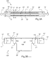
- FIG. 3A and 3B A diagram of a microfluidic device 100' for producing an emulsion is shown in Figures 3A and 3B (cross-section along the dotted line) according to a first embodiment, compliant with the principle of Figure 2A .
- the dimensions of the microfluidic parts of such microfluidic device 100' can be about 10 cm (length L0) x 1 cm (width W0).
- the height of the device would be the biggest height amongst h1, h2b.
- Microfluidic device 100' comprises a first channel 10', a second channel 20', and two facing arrays 31',32' of microchannels 30' linking the first channel 10' to the second channel 20'.
- each array 31',32' comprises 1000 microchannels 30'.
- Each microchannel 30' has an inlet 33' from the first channel 10' and an outlet 34' to the second channel 20' (see Figure 3B ).
- the second channel 20' is, in the present invention, centrally positioned in the device between the two arrays of microchannels 30', and is straight.
- the second channel 20' comprises an entry port 23' for the continuous phase, and an exit port 24' for the emulsion formed by using the device.
- the continuous phase flows form the entry port 23' towards the exit port 24' where the emulsion is collected.
- the second channel 20' is characterized by two different heights (h2a and h2b): a first part 21' with the smallest height (h2a) located along the arrays of microchannels 30', and a second part 22' with the bigger height (h2b) located in the center of the second channel 20'.
- a lengthwise direction L0 of the device is considered to be the direction of a flow along the second channel 20'.
- the first channel 10' here comprises an entry port 13' for the phase to be dispersed, and an exit port 14' for the phase to be dispersed which is configured to be open or closed.
- the phase to be dispersed is forced through the arrays of microchannels 30' that lead to the second channel 20' where the continuous phase flows from the entry port 23' towards the emulsion exit port 24' where the emulsion is collected.
- the first channel 10' is split in two parts 11',12', the first array 31' of microchannels 30' being situated between a first part 11' of the two parts of the first channel 10' and the second channel 20', and the second array 32' of microchannels 30' being situated between a second part 12' of the two parts of the first channel 10' and the second channel 20'.
- the two parts 11',12' of the first channel 10' surround the two arrays 31',32' of microchannels 30' and the second channel 20'.
- height h1 of the first channel 10' (in particular here of both parts 11',12') and height h2a of the first part 21' of the second channel 20' are equal to 20 ⁇ m
- height h0 of the microchannel 30' is equal to 2 ⁇ m
- height h2b of the second part 22' of the second channel 20' is equal to 200 ⁇ m.
- each microchannel 30' has a length L, and at least a part with a width W (considered along the lengthwise direction of the device).
- the width W is equal to about 10 ⁇ m, and the length (considered between its inlet and its outlet) is equal to about 140 ⁇ m.
- a distance e between two successive microchannels 30' is for example equal to 40 ⁇ m.
- a microfluidic device with a design as shown in Figures 3A and 3B is advantageously made of glass.
- the channels can be made by a wet etching method leading to bottom corners of channels having a rounded shape characterized by a radius of curvature equal to the channel's height.
- FIG. 4 Various example methods to manufacture a device according to the invention are illustrated in Figure 4 .
- a device according to the invention can be made by assembling a bottom plate with a top plate.
- At least part of the first channel, the second channel, and/or the microchannels can be formed in at least the bottom plate.
- Figure 4 shows a microchannel cross-section.
- the top plate with which it is then assembled can be flat, as illustrated in Figures 4D), 4E) and 4F ), or etched too, as illustrated in Figures 4G), 4H) and 4I ).
- the bottom plate and the top plate assembled one to the other can be etched with different techniques if desired.
- 3D printing for example stereolithography, could also be used to manufacture at least part of the device.
- microchannels can have different shapes along their length.
- Figure 5A shows microchannels having a constant width W along their length L.
- Figure 5B shows microchannels having a first part with a constant width W along their length L1 and a second part which is flared along their length L2.
- Figure 5C shows microchannels having a first part with a constant width W along their length L1' and a second part which is common to several microchannels along their length L2', corresponding to coalescence of several microchannels.
- the second parts of the microchannels have a same height h0.
- the phase to be dispersed 2a is decane (which is an alkane composed of a linear chain of ten atoms of carbon (C)), the continuous phase 2c is water with sodium dodecyl sulphate.
- the flows of both phases are controlled by imposing a pressure on each reservoir containing the liquids and which are connected to the corresponding entry ports of the microfluidic device.
- oil-in-water drops 2b are formed at the end of the microchannels 30', forming a compact emulsion having homogeneous size as revealed by the arrangement of the drops in a crystal like fashion.
- the compact emulsion then flows to the central part 22' of the collecting second channel 20' having a greater height and where most of the continuous phase 2c flows.
- the pressure (Pd) of the phase to be dispersed 2a is set to 500 mbar.
- the production rate depends mainly on the pressure (Pd) of the phase to be dispersed and weakly on the pressure (Pc) of the continuous phase thanks to the design of the microfluidic device according to the invention.
- the first microchannel is located close to the entry port of the continuous phase.
- Two pressures of the continuous phase (Pc) are used as in Figure 6 .
- the pressure of the phase to be dispersed is set to 500 mbar.
- the average frequency of drop formation per microchannel is about 130 Hz. This results in an overall production rate of the device of 2.6x10 5 drops per second.
- the average drop size is 8.5 ⁇ m and the corresponding coefficient of variation (CV), defined as the standard deviation of the size distribution divided by the mean size, is 7.5 % (as illustrated by Figure 8 ).
- the corresponding throughput is 0.3 mL of phase to be dispersed per hour.
- the microfluidic device can continuously produce emulsion drops over several days or weeks.
- SDS sodium dodecyl sulphate
- the average frequency of drop formation per microchannel is 90 Hz and the resulting drop size is 8.4 ⁇ m and the size distribution is characterized by a coefficient of variation of 4.8 %.
- the phase to be dispersed 2a comprises styrene, divinylbenzene, and nanoparticles of iron oxide covered by oleic acid; and the continuous phase 2c is water with of sodium dodecyl sulphate.
- the average frequency of drop formation per microchannel is 30 Hz and the resulting mean drop size is 8.2 ⁇ m and the size distribution is characterized by a coefficient of variation of 7.2 %.
- a microfluidic device 100" according to a second embodiment of the invention is shown in Figure 9 .
- the device 100 differs from the previous one illustrated on Figure 3 by the design of the first channel 10", which is here made tortuous and split into several sub-channels, and in that there is no exit port for the phase to be dispersed in the first channel.
- the device 100" is fabricated by soft lithography techniques.
- PDMS polydimethylsiloxane
- the height of the microchannels (h0) is 2.3 ⁇ m
- the width W is 10 ⁇ m and the length L is 140 ⁇ m
- the height of the first channel (h1) and of the first part of the second channel (h2a) is 20 ⁇ m
- the height (h2b) of the second part of the second channel (collecting channel) is 240 ⁇ m.
- Each array contains 500 microchannels, or a total of 1000 microchannel for the device.
- the pressure (Pd) of the phase to be dispersed is set to 350 mbar.
- the oil-in-water drops 2b are formed at the end of the microchannels 30", forming a compact emulsion having homogeneous size as revealed by the arrangement of the drops 2b in a crystal like fashion.
- the compact emulsion then flows to the central part 22" of the collecting second channel 20" having a higher height and where most of the continuous phase 2c is flowing. This makes it possible to dilute the emulsion and thus to obtain a continuous production and collection of the emulsion at a high throughput.
- Figure 11 shows the production rate of about twenty microchannels at three locations along the array of microchannels 30" of the PDMS device 10" shown in Figure 9 .
- the first microchannel 30" is located close to the entry port 23" of the continuous phase 2c.
- the frequency of drop formation along the array of microchannels 30" is not affected by a modification of Pc.
Landscapes
- Chemical & Material Sciences (AREA)
- Chemical Kinetics & Catalysis (AREA)
- Health & Medical Sciences (AREA)
- Analytical Chemistry (AREA)
- General Health & Medical Sciences (AREA)
- Hematology (AREA)
- Clinical Laboratory Science (AREA)
- Physical Or Chemical Processes And Apparatus (AREA)
- Colloid Chemistry (AREA)
Abstract
Description
- The present invention relates to an emulsion production microfluidic device.
- An emulsion is a mixture of at least two liquids that are normally immiscible. By definition, one liquid (called dispersed phase) is dispersed in another (called continuous phase).
- There are two main types of emulsion: a direct emulsion which is like an oil-in-water emulsion, wherein the oil is the dispersed phase and water is the continuous phase, and an inverse emulsion which is like a water-in-oil emulsion, wherein water is the dispersed phase and oil is the continuous phase.
- The phase to be dispersed can be a mixture of several miscible fluids, a solution of small molecules, macromolecules, amphiphilic or not, or a dispersion of particles, solid or liquid, the latter thus forming a double, or multiple, emulsion, or a combination of the various above-mentioned options.
- The continuous phase generally contains one or more surfactants (amphiphilic molecules), as well as solutes, polymers or even particles.
- Emulsification methods to obtain drops of a few micrometers diameter are known, such as an emulsification method by shearing obtained using a device comprising two coaxial cylinders, one of which being rotary, or an emulsification method by a membrane which is based on the use of a porous material through which a phase to be dispersed is injected.
- However, these methods lead to emulsion drops characterized by a coefficient of size variation, defined as the ratio between the mean drop size and the standard deviation of the drop sizes, of at least about 15%.
- Therefore, microfluidics has appeared an efficient tool for obtaining calibrated emulsion drops.
- For example, a microfluidic device is described in
U.S. Patent Application No. 14/890,817 . - In such a device, a phase to be dispersed passes from a first channel to a second channel via microchannels arranged parallel to each other, a height of the microchannels being smaller than that of the channels.
- Drops are formed at one end of the microchannels, which meets the second channel in which a continuous phase is injected, transversely to the microchannel network. The size of the drops is proportional to the height of the microchannel, with a smaller dependence on the width of the microchannel. The size of the drops is weakly dependent on the flow rate of the phase to be dispersed in the microchannels, which depends on the pressures on either side of said microchannels, below a critical flow rate. Beyond this critical flow rate, the size of the drops is much larger and leads to a wide size distribution within the microchannel network.
- Furthermore, the emulsion drops that are in the second channel are moved by the continuous phase toward an output of the device, to which a tank is connected.
- As the microchannels are arranged in series, transversely to the second channel, the amount of drops in the continuous phase increases along the direction of flow of the continuous phase.
- An emulsion which is too concentrated could lead to a detrimental effect on the production of this emulsion: increasing the volume fraction of the phase to be dispersed (i.e. the drops) in the continuous phase increases the viscosity of the emulsion and thus the corresponding pressure losses. Besides, adhesion force existing between the drops increases this effect.
- For flow control by pressure regulation, the pressure of the continuous phase must then be modulated in order to avoid clogging the device.
- However, flow control can be difficult to use for small drop sizes whose rate of production is relatively low. It is often necessary to impose a high flow rate of the continuous phase to sufficiently dilute the emulsion.
- Furthermore, the pressure conditions at the first microchannels can be disadvantageous. The flow of the phase to be dispersed through a microchannel depends on the pressure on either side of this microchannel. Increasing the pressure of the continuous phase in order to avoid clogging the device thus amounts to altering, or even stopping, part of the drop production of the microchannels located upstream.
- The invention relates to a microfluidic device for producing emulsions, in which the size of the drops shows great homogeneity, namely a size dispersion coefficient lower than or equal to 15 %, or even 10 %, and an average size, for example mean size, of a few micrometers, for example which may vary from a few micrometers to a few tens of micrometers, or a few hundred micrometers.
- The invention also relates to a microfluidic device, which enables the production conditions of an emulsion to be improved, for example enables continuous and mass production of this emulsion.
- Accordingly, the invention provides an emulsion production microfluidic device, which comprises:
- A first channel, comprising an entry port configured to inject, into the first channel, a phase to be dispersed,
- A second channel, comprising an entry port configured to inject a continuous phase into this second channel, and an emulsion exit port configured to extract an emulsion from the device, and
- At least one array of microchannels, arranged side by side, each microchannel comprising an inlet from the first channel, and an outlet to the second channel, a height h0 of each of the microchannels being smaller than a height h1 of the first channel,
- Thus, the invention decouples the drop formation step (i.e. emulsification step) to constitute the emulsion, thanks to a compact emulsion along the microchannels, and the emulsion collection step owing to a transverse flow for diluting the emulsion and thus facilitate its flow out of the device.
- The invention allows to homogenize the flows at the outlets of the microchannels and to create a variation of the hydrodynamic resistances between the first and second part of the second channel.
- To this end, the invention separates the second channel in two parts: the first part of which is configured to implement the drop formation step out of the microchannels, and the second part of which is configured to implement a drop collection step.
- The second channel is characterized by at least two different heights:
- The first part, near the microchannels, is characterized by a height h2a a few times greater than that of the microchannels, and
- The second part, adjacent to the first part, is characterized by at least a height h2b a few times greater than that of the first part.
- Such device is also called "closed device" as it comprises an entry port for the phase to be dispersed, an emulsion exit port, and a flow, running in the device, which enables to collect the drops which are formed in the device (i.e. the emulsion is formed in the device).
- The height h2a of the first part of the second channel is preferably constant or can slightly vary from the microchannels to the second part, for example increase, but in any case, the height h2a of the first part is significantly greater than the height h0 of the microchannels and the height h2b of the second part of the second channel is significantly greater that the height h2a if the first part.
- Here, a lengthwise direction of the device is considered to be the direction of a flow along the second channel between the entry port and the emulsion exit port. Moreover, a width direction of the device is considered to be a direction orthogonal to the lengthwise direction of the device, and a height direction is orthogonal to the lengthwise and width directions.
- Furthermore, it is considered that a lengthwise direction of a microchannel is a direction from the inlet to the outlet of the microchannel. A width direction of the microchannel is orthogonal to its lengthwise direction; it extends parallel to the lengthwise direction of the device if the microchannel is perpendicular to the second channel. A height direction of the microchannel is parallel to the height direction of the device.
- Same applies to the first channel which has a height direction parallel to the height direction of the device.
- The height h0 of at least one microchannel of the array of microchannels is considered as constant.
- For example, h0 is equal to about 2 µm.
- A microchannel comprises at least a part (along its length) with a constant width W.
- According to an example embodiment, a microchannel can comprise a part with an increased width, for example a flared part. Such part is preferably between the part with a constant width and the second channel.
- According to an example embodiment, the parts of at least two microchannels with a constant width W coalesce.
- For example, the array of microchannels comprises a part which is common to at least two microchannels, with a same height h0, at the outlet location.
- For example, the width W of at least a part of a microchannel is comprised between 2 and 100 times its height h0, for example between 2 and 20, preferably equal to 5 times the height h0.
- For example, W is equal to about 10 µm.
- For example, microchannels with a constant width along its length of about 10 µm (width) x 2 µm (height) are configured to produce drops with a diameter d of about 8 µm.
- For example, a length of a microchannel is comprised between 2 and 1000 times its height h0, preferably 100 times.
- Selection of the length, combined with the height, enables regulation of the hydrodynamic resistance of the microchannel.
- For example, a distance e between two successive microchannels is comprised between 2 to 100 times the width W of a microchannel, for example equal to about 4 times the width W of a microchannel.
- According to an example embodiment, the microchannels have a cross-section of rectangular shape, or of a half-cylinder shape, or of a triangle shape.
- For example, at least one corner of the rectangular cross-section is a right angle, or is curved, for example rounded, or beveled.
- For example, the array of microchannels comprises at least 10 microchannels, for example between 100 and 100000 microchannels, preferably about 1000 microchannels.
- For example, a microfluidic part of the device preferably has a length L0 comprised between 2 cm and 20 cm, a width W0 between 0,5 cm and 10 cm, and a height between 0,1 cm and 2 cm.
- The pressure, and thus the flow, of the continuous phase, can be adjusted in order to dilute the emulsion during production as desired, without altering the emulsification process, and this enables optimal production of the emulsion, without intermittence, that is to say continuous production.
- As a consequence, the number of microchannels can be increased, compared to a device having a second channel of a single height, which further enhances the production rate.
- In such device, a phase to be dispersed is introduced into the first channel via its entry port.
- The first channel can optionally also comprise an exit port for the phase to be dispersed which is configured to be open or closed.
- When the exit port of the first channel is closed, the phase to be dispersed is forced to pass through the array of microchannels that lead to the second channel. When the exit port of the first channel is open, it is possible to purge the first channel without the need to flow through the array of microchannels.
- When the phase to be dispersed passes from the first channel to the first part of the second channel via the microchannels, drops are formed at the end of the microchannels which meets the first part of the second channel.
- Simultaneously, the continuous phase is injected into the second channel via its entry port, and moves the drops to the emulsion exit port of the second channel.
- For example, the second channel can be straight, for example at least between its entry port and its emulsion exit port.
- However, the second channel can be tortuous. This can enable a further increase in the number of microchannels, and therefore, the production rate.
- For example, the emulsion exit port of the second channel is configured to connect a tank to collect the emulsion.
- For example, such device can be used to produce drops to synthetize functionalized solid particles which can be useful in the biotechnology field.
- According to an example embodiment, the device comprises two arrays of microchannels.
- According to an example embodiment, one array of microchannels is set on both sides of at least one of the first channel or the second channel.
- For example, the device can comprise at least two of the first channels, a first array of microchannels of the two arrays of microchannels being situated between a first of the two first channels and the second channel, and a second array of microchannels of the two arrays of microchannels being situated between a second of the two first channels and the second channel.
- For example, the device can comprise at least two of the second channels, a first array of microchannels of the two arrays of microchannels being situated between a first of the two second channels and the first channel, and a second array of microchannels of the two arrays of microchannels being situated between a second of the two second channels and the first channel.
- The first part of the second channel has a height h2a.
- For example, the height h2a of the first part of the second channel is from 2 to 100 times greater than the height h0 of a microchannel, preferably 10 times.
- For example, h2a is equal to about 20 µm.
- For example, the height h2b of the second part of the second channel is from 2 to 100 times greater than the height h2a of the first part of the second channel, preferably 10 times.
- For example, h2b is equal to about 200 µm.
- The first channel has a height h1.
- For example, the height h1 of the first channel is from 2 to 1000 times greater than the height h0 of a microchannel, preferably 10 times.
- According to an example, the height h1 of the first channel is equal to the height h2a of the first part of the second channel.
- For example, h1 is equal to about 20 µm.
- For example, the first channel has a width comprised between 1 to 100 times its height h1.
- For example, the second channel has a width comprised between 1 to 100 times the height h2b of its second part.
- The microfluidic device is advantageously made of glass, since glass is compatible with most solvents, and thus it is possible to use more varied emulsion formulations.
- Also, microfabrication techniques using glass substrates lead to accurate and reproducible microchannel features.
- According to another advantageous example, the device can be made of silicon.
- For example, to limit, or even prevent, wetting of the glass by the phase to be dispersed, particularly when it comprises an organic phase, and ensure an efficient emulsification step, it is desirable that at least some of the surfaces of the first channel, the second channel, and/or the microchannels are hydrophilic (or hydrophilic), and remain hydrophilic (or hydrophilic) as long as possible during the emulsion production.
- Moreover, according to an interesting option, the surface properties can be modified to make them hydrophilic or hydrophobic, depending on the type of emulsion to produce.
- To this end, according to one embodiment, a hydrophilic molecule is adsorbed or grafted in at least part of the surfaces of the first channel, and/or the second channel, and/or the microchannel, to make the surface hydrophilic, or a hydrophobic molecule is adsorbed or grafted in at least part of the surfaces of the first channel, and/or the second channel, and/or the microchannel, to make the surface hydrophobic.
- If possible, a hydrophilic, or a hydrophobic, molecule is applied to the whole surface of the first channel, the second channel and the microchannels.
- The hydrophilic or hydrophobic molecule can be characterised by high adhesion energy to the surface.
- According to an embodiment, the hydrophilic or hydrophobic molecule can be a polymer.
- An interesting hydrophilic molecule can be a silane coupled with Poly(ethylene glycol) (PEG), in particular for a device made of glass or silicon for example.
- An interesting hydrophobic molecule can be a silane, in particular for a device made of glass or silicon for example.
- A related method can be as follows.
- For example, the surface is activated with a piranha solution, i.e. a solution comprising sulphuric acid with hydrogen peroxide (H2O2).
- Next, the surface is rinsed and after, the surface is functionalized with a hydrophilic or hydrophobic solution.
- For example, the hydrophilic or hydrophobic molecule that prevent wetting of the organic phase is adsorbed on the surface.
- For example, the hydrophilic or hydrophobic molecule which prevents wetting of the organic phase is covalently bonded on the surface.
- According to one example embodiment, several devices comprising at least some of the above-mentioned features, can be placed and used in parallel.
- This can further increase the production rate of an emulsion.
- For example, a manufacturing method of such a device, comprising at least some of the above-mentioned features, can comprise the following steps:
- Providing a plate, called here bottom plate;
- Forming at least a part of the first channel, and/or the second channel, and/or the microchannels in the bottom plate;
- Assembling the bottom plate with a plate, here called top plate, to form the device.
- For example, at least part of the first channel, and/or the second channel, and/or the microchannels can be formed by etching, wet or dry, or soft lithography or by 3D printing techniques, like stereolithography.
- According to an example, the method can also comprise a step of forming a complementary part of the first channel, the second channel, and/or the microchannels in the top plate.
- For example, the complementary part of the first channel, and/or the second channel, and/or the microchannels can be formed by etching, wet or dry, or soft lithography or by 3D printing techniques, like stereolithography.
- This step preferably occurs before assembling the top plate with the bottom plate.
- For example, etching the bottom plate and/or the top plate can comprise anisotropic etching.
- For example, etching the bottom plate and/or the top plate can comprise isotropic etching.
- Of course, many other techniques may be utilized.
- Besides, different techniques can be applied to the bottom plate and the top plate configured to be assembled one to the other if required.
- According to another embodiment, the second part of the second channel can be formed by etching a glass substrate (top plate and/or bottom plate) to obtain a half-cylinder, or a triangle if the substrate is made of silicon (making the top plate and/or the bottom plate).
- According to another embodiment, at least part of the device can also be made by 3D printing methods, for example stereolithography, enabling different shapes to be provided.
- Additional features and advantages of the present invention are described in, and will be apparent from, the description of the presently preferred embodiments which are set out below with reference to the drawings in which:
-
Figure 1 diagrammatically shows a cross section of a microfluidic device 1 according to prior art. -
Figure 2A diagrammatically shows a cross section of amicrofluidic device 100 according to the present invention. -
Figure 2B illustrates an experimental manufacture and use of a device according tofigure 2A . -
Figure 3A shows a diagram of a microfluidic device 100' for producing an emulsion according to a first embodiment compliant with the one offigure 2A (figures 3A), and Figure 3B shows a corresponding cross-section along the dotted line A-A. -
Figure 4 , comprisingfigures 4A to 4I , illustrates various methods to manufacture channels or microchannels in a device according to the invention. -
Figure 5 shows three embodiments of microchannels according to the invention. -
Figure 6 shows snapshots of a microfluidic device according to the embodiment ofFigure 3A that produces emulsion for two different pressures (Pc) of the continuous phase while the pressure of the phase to be dispersed is set to 500 mbar. The heights of the different channels are indicated. -
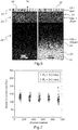
Figure 7 represents frequency of drops formation as a function of the microchannel's number along the array of microchannels of a glass device according to the embodiment ofFigure 3A and the experiment ofFigure 6 . -
Figure 8 illustrates a drop size distribution of an emulsion produced with a device according toFigure 3A with decane as a phase to be dispersed. -
Figure 9 diagrammatically shows a microfluidic device according to a second embodiment of the invention. -
Figure 10 shows snapshots of a microfluidic device according to the embodiment ofFigure 9 that produces emulsion for two different pressures (Pc) of the continuous phase. The pressure of the phase to be dispersed is set to 350 mbar. The heights of the different areas are also indicated. -
Figure 11 shows frequency of drops formation as a function of the microchannel's number along the array of microchannels of a PDMS device according to the embodiment ofFigure 9 . The first microchannel is located close to the entrance of the continuous phase. Two pressures of the continuous phase (Pc) are used as inFigure 10 . The pressure of the phase to be dispersed is set to 350 mbar. -
Figure 1 diagrammatically shows a cross section of a microfluidic device 1 according to prior art. - This device 1 comprises a first channel 1a, a
second channel 1b, andmicrochannel 1c, linking the first channel to the second channel. - In use, a phase to be dispersed 2a, for example including at least an organic phase, is injected into the first channel 1a. The phase to be dispersed 2a passes through the
microchannels 1c and forms adrop 2b at an end of the microchannel meeting thesecond channel 1b. In thesecond channel 1b, acontinuous phase 2c, for example an aqueous phase, is injected and moves thedrops 2b to an emulsion exit port of the device. - The
drops 2b in thecontinuous phase 2c form an emulsion. - According to such embodiment, the
microchannel 1c has a height h0 which is smaller than a height h1 of the first channel 1a and a height h2 of thesecond channel 1b. - As illustrated on
Figure 1 , thesecond channel 1b has a uniform height. - A drawback of such embodiment is that the device, in particular at least the
second channel 1b, can be easily clogged, and monitoring a continuous flow of the emulsion is difficult. -
Figure 2A diagrammatically shows a cross section of amicrofluidic device 100 according to the invention. - This
device 100 comprises afirst channel 10, asecond channel 20, and amicrochannel 30, linking thefirst channel 10 to thesecond channel 20. - In use, a phase to be dispersed 2a, for example including at least an organic phase, is injected into the
first channel 10. The phase to be dispersed 2a passes through themicrochannel 30 and forms adrop 2b at anoutlet 34 of the microchannel meeting thesecond channel 20. In thesecond channel 20, acontinuous phase 2c, for example an aqueous phase, is injected and moves thedrops 2b to an emulsion exit port of the device. - The
drops 2b in thecontinuous phase 2c form an emulsion. - In this embodiment, the
second channel 20 comprises afirst part 21 which theoutlet 34 of themicrochannel 30 meets, and asecond part 22, thefirst part 21 being between the microchannel 30 and thesecond part 22. - According to such embodiment, the
microchannel 30 has a height h0 which is smaller than a height h1 of thefirst channel 10. Besides, thefirst part 21 has a height h2a greater than the height h0 of the microchannel, and thesecond part 22 has a height h2b greater than the height h2a of thefirst part 21. - According to a particular embodiment, h0 = 2 µm, h2a = 20 µm, and h2b = 200 µm.
-
Figure 2B illustrates an experimental manufacture of a device according toFigure 2A . - According to an example of utilization of the device, a phase to be dispersed 2a is introduced in the first channel.
- In parallel, a
continuous phase 2c, potentially comprising an aqueous phase, is introduced in thesecond channel 20. -
Figure 2B shows that the emulsion is compact in thefirst part 21 of thesecond channel 20, and is then diluted in thesecond part 22 of thesecond channel 20, which ensures a better continuous flow, and therefore a more continuous production of the emulsion. - A diagram of a microfluidic device 100' for producing an emulsion is shown in
Figures 3A and 3B (cross-section along the dotted line) according to a first embodiment, compliant with the principle ofFigure 2A . - In one embodiment, the dimensions of the microfluidic parts of such microfluidic device 100' can be about 10 cm (length L0) x 1 cm (width W0). For example, the height of the device would be the biggest height amongst h1, h2b.
- Microfluidic device 100' comprises a first channel 10', a second channel 20', and two facing arrays 31',32' of microchannels 30' linking the first channel 10' to the second channel 20'.
- In one embodiment, each array 31',32' comprises 1000 microchannels 30'.
- Each microchannel 30' has an
inlet 33' from the first channel 10' and anoutlet 34' to the second channel 20' (seeFigure 3B ). - The second channel 20' is, in the present invention, centrally positioned in the device between the two arrays of microchannels 30', and is straight.
- The second channel 20' comprises an entry port 23' for the continuous phase, and an exit port 24' for the emulsion formed by using the device. In use, the continuous phase flows form the entry port 23' towards the exit port 24' where the emulsion is collected.
- As shown in
Figure 3B , the second channel 20' is characterized by two different heights (h2a and h2b): a first part 21' with the smallest height (h2a) located along the arrays of microchannels 30', and a second part 22' with the bigger height (h2b) located in the center of the second channel 20'. - Here, a lengthwise direction L0 of the device is considered to be the direction of a flow along the second channel 20'.
- The first channel 10' here comprises an entry port 13' for the phase to be dispersed, and an exit port 14' for the phase to be dispersed which is configured to be open or closed.
- When the exit port 14' for the phase to be dispersed is closed, the phase to be dispersed is forced through the arrays of microchannels 30' that lead to the second channel 20' where the continuous phase flows from the entry port 23' towards the emulsion exit port 24' where the emulsion is collected.
- In this embodiment, the first channel 10' is split in two parts 11',12', the first array 31' of microchannels 30' being situated between a first part 11' of the two parts of the first channel 10' and the second channel 20', and the second array 32' of microchannels 30' being situated between a second part 12' of the two parts of the first channel 10' and the second channel 20'.
- Therefore, here, the two parts 11',12' of the first channel 10' surround the two arrays 31',32' of microchannels 30' and the second channel 20'.
- Here, height h1 of the first channel 10' (in particular here of both parts 11',12') and height h2a of the first part 21' of the second channel 20' are equal to 20 µm, height h0 of the microchannel 30' is equal to 2 µm, and height h2b of the second part 22' of the second channel 20' is equal to 200 µm.
- Besides, each microchannel 30' has a length L, and at least a part with a width W (considered along the lengthwise direction of the device).
- For example, the width W is equal to about 10 µm, and the length (considered between its inlet and its outlet) is equal to about 140 µm.
- A distance e between two successive microchannels 30' is for example equal to 40 µm.
- A microfluidic device with a design as shown in
Figures 3A and 3B is advantageously made of glass. - According to an example, the channels can be made by a wet etching method leading to bottom corners of channels having a rounded shape characterized by a radius of curvature equal to the channel's height.
- Various example methods to manufacture a device according to the invention are illustrated in
Figure 4 . - For example, a device according to the invention can be made by assembling a bottom plate with a top plate.
- At least part of the first channel, the second channel, and/or the microchannels can be formed in at least the bottom plate.
- For illustration,
Figure 4 shows a microchannel cross-section. - To this end, the following techniques can be used:
- Anisotropic etching or soft lithography, which usually lead to a rectangular cross section with right angle corners as shown in
Figure 4A ), - Isotropic etching, which usually leads to:
- ▪ rounded corners when applied on a glass substrate as illustrated in
Figure 4B ), - ▪ beveled corners when applied on a silicon substrate as illustrated in
Figure 4C ).
- ▪ rounded corners when applied on a glass substrate as illustrated in
- The top plate with which it is then assembled can be flat, as illustrated in
Figures 4D), 4E) and 4F ), or etched too, as illustrated inFigures 4G), 4H) and 4I ). - The bottom plate and the top plate assembled one to the other can be etched with different techniques if desired.
- According to another embodiment, 3D printing, for example stereolithography, could also be used to manufacture at least part of the device.
- As illustrated in
Figure 5 , microchannels can have different shapes along their length. - According to one embodiment,
Figure 5A shows microchannels having a constant width W along their length L. - According to a second embodiment,
Figure 5B shows microchannels having a first part with a constant width W along their length L1 and a second part which is flared along their length L2. - According to a third embodiment,
Figure 5C shows microchannels having a first part with a constant width W along their length L1' and a second part which is common to several microchannels along their length L2', corresponding to coalescence of several microchannels. - The second parts of the microchannels have a same height h0.
- The phase to be dispersed 2a is decane (which is an alkane composed of a linear chain of ten atoms of carbon (C)), the
continuous phase 2c is water with sodium dodecyl sulphate. - The flows of both phases are controlled by imposing a pressure on each reservoir containing the liquids and which are connected to the corresponding entry ports of the microfluidic device.
- As shown in
Figure 6 , oil-in-water drops 2b are formed at the end of the microchannels 30', forming a compact emulsion having homogeneous size as revealed by the arrangement of the drops in a crystal like fashion. - The compact emulsion then flows to the central part 22' of the collecting second channel 20' having a greater height and where most of the
continuous phase 2c flows. - This makes it possible to dilute the emulsion and thus to obtain a continuous production and collection of the emulsion at a high throughput.
- The snapshots provided in
Figure 6 are taken at the end of the microchannel array for two different pressures (Pc) of thecontinuous phase 2c, namely Pc=100 mbar for the left hand picture, and Pc=200 mbar for the right hand picture. The pressure (Pd) of the phase to be dispersed 2a is set to 500 mbar. -
Figure 6 clearly shows that the collected emulsion is more diluted for a higher value of Pc. - The production rate depends mainly on the pressure (Pd) of the phase to be dispersed and weakly on the pressure (Pc) of the continuous phase thanks to the design of the microfluidic device according to the invention.
- The production rates of about twenty microchannels at five locations along the array of microchannels of a glass device as shown in
Figures 3A and 3B are shown inFigure 7 . - The first microchannel is located close to the entry port of the continuous phase. Two pressures of the continuous phase (Pc) are used as in
Figure 6 . The pressure of the phase to be dispersed is set to 500 mbar. - As reported in
Figure 7 , the frequency of drop formation along the array of microchannels is not affected by a modification of Pc. - The average frequency of drop formation per microchannel is about 130 Hz. This results in an overall production rate of the device of 2.6x10⁵ drops per second.
- The average drop size is 8.5 µm and the corresponding coefficient of variation (CV), defined as the standard deviation of the size distribution divided by the mean size, is 7.5 % (as illustrated by
Figure 8 ). - The corresponding throughput is 0.3 mL of phase to be dispersed per hour.
- The microfluidic device can continuously produce emulsion drops over several days or weeks.
- The phase to be dispersed 2a is a certified refractive index liquid (Series AA-xx with n= 1.41, #1806Y, from Cargille Laboratories) and the
continuous phase 2c is an aqueous solution of sodium dodecyl sulphate (SDS). - For a set of pressures, the average frequency of drop formation per microchannel is 90 Hz and the resulting drop size is 8.4 µm and the size distribution is characterized by a coefficient of variation of 4.8 %.
- Still using device of
Figure 3 , the phase to be dispersed 2a comprises styrene, divinylbenzene, and nanoparticles of iron oxide covered by oleic acid; and thecontinuous phase 2c is water with of sodium dodecyl sulphate. - For a set of pressures, the average frequency of drop formation per microchannel is 30 Hz and the resulting mean drop size is 8.2 µm and the size distribution is characterized by a coefficient of variation of 7.2 %.
- A
microfluidic device 100" according to a second embodiment of the invention is shown inFigure 9 . - Similar parts bear same numeral reference with an additional "'".
- The
device 100" differs from the previous one illustrated onFigure 3 by the design of thefirst channel 10", which is here made tortuous and split into several sub-channels, and in that there is no exit port for the phase to be dispersed in the first channel. - For example, the
device 100" is fabricated by soft lithography techniques. - It is made in polydimethylsiloxane (PDMS) and bonded on a glass plate.
- In one embodiment, the height of the microchannels (h0) is 2.3 µm, the width W is 10 µm and the length L is 140 µm, the height of the first channel (h1) and of the first part of the second channel (h2a) is 20 µm and the height (h2b) of the second part of the second channel (collecting channel) is 240 µm.
- Each array contains 500 microchannels, or a total of 1000 microchannel for the device.
- An emulsion composed of fluorocarbon oil (FC40, 3M Fluorinert) as the phase to be dispersed 2a and an aqueous solution of sodium dodecyl sulphate as the
continuous phase 2c is produced with the microfluidic device reported inFigure 9 . -
Figure 10 shows snapshots taken at the end of the microchannel array for two different pressures (Pc) of thecontinuous phase 2c, namely Pc=200 mbar for the left hand picture, and Pc=600 mbar for the right hand picture. The pressure (Pd) of the phase to be dispersed is set to 350 mbar. - As shown in this figure, the oil-in-water drops 2b are formed at the end of the
microchannels 30", forming a compact emulsion having homogeneous size as revealed by the arrangement of thedrops 2b in a crystal like fashion. - The compact emulsion then flows to the
central part 22" of the collectingsecond channel 20" having a higher height and where most of thecontinuous phase 2c is flowing. This makes it possible to dilute the emulsion and thus to obtain a continuous production and collection of the emulsion at a high throughput. - It is clearly visible that the collected emulsion is more diluted for a higher value of Pc.
-
Figure 11 shows the production rate of about twenty microchannels at three locations along the array ofmicrochannels 30" of thePDMS device 10" shown inFigure 9 . - The
first microchannel 30" is located close to theentry port 23" of thecontinuous phase 2c. - As illustrated by this figure, the frequency of drop formation along the array of
microchannels 30" is not affected by a modification of Pc.
Claims (12)
- An emulsion production microfluidic device which comprises:- A first channel, comprising an entry port configured to inject, into the first channel, a phase to be dispersed,- A second channel, comprising an entry port configured to inject a continuous phase into this second channel, and an emulsion exit port configured to extract an emulsion from the device, and- At least one array of microchannels, arranged side by side, each microchannel comprising an inlet from the first channel, and an outlet to the second channel, a height h0 of each of the microchannels being smaller than a height h1 of the first channel,the device being characterized in that the second channel comprises a first part connected to the outlet of each microchannel and at least a second part along the first part, the first part being between the array of microchannels and the second part, the first part having a height h2a greater that the height h0 of each microchannel, and the second part having a height h2b greater than the height h2a of the first part.
- Device according to claim 1, characterized in that at least one microchannel comprises at least a part with a constant width W.
- Device according to claim 2, characterized in that the width W of at least a part of a microchannel is comprised between 2 to 100 times its height h0, preferably equal to 5 times.
- Device according to anyone of claims 1 to 3, characterized in that at least one microchannel comprises a flared part.
- Device according to anyone of claims 1 to 4, characterized in that the array of microchannels comprises a part which is common to at least two microchannels at the outlet location.
- Device according to anyone of claims 1 to 5, characterized in that the array of microchannels comprises at least 10 microchannels, for example between 100 and 100000 microchannels, preferably about 1000 microchannels.
- Device according to anyone of claims 1 to 6, characterized in that the height h2a of the first part of the second channel is from 2 to 100 times greater than the height h0 of a microchannel, preferably 10 times.
- Device according to anyone of claims 1 to 7, characterized in that the height h2b of the second part of the second channel is from 2 to 100 times greater than the height h2a of the first part of the second channel, preferably 10 times.
- Device according to anyone of claims 1 to 8, characterized in that the height h1 of the first channel is from 2 to 1000 times greater than the height h0 of a microchannel, preferably 10 times.
- Device according to anyone of claims 1 to 9, characterized in that the first channel has a width comprised between 1 to 100 times its height h1.
- Device according to anyone of claims 1 to 10, characterized in that the second channel has a width comprised between 1 to 100 times the height h2b of its second part.
- Device according to anyone of claims 1 to 11, characterized in that a hydrophilic molecule is adsorbed or grafted in at least part of the surfaces of the first channel, and/or the second channel, and/or the microchannel, to make the surface hydrophilic, or a hydrophobic molecule is adsorbed or grafted in at least part of the surfaces of the first channel, and/or the second channel, and/or the microchannel, to make the surface hydrophobic.
Priority Applications (11)
| Application Number | Priority Date | Filing Date | Title |
|---|---|---|---|
| EP19305477.2A EP3721980B1 (en) | 2019-04-12 | 2019-04-12 | Emulsion production microfluidic device |
| PL19305477.2T PL3721980T3 (en) | 2019-04-12 | 2019-04-12 | Emulsion production microfluidic device |
| DK19305477.2T DK3721980T3 (en) | 2019-04-12 | 2019-04-12 | Microfluidic device for emulsion production |
| ES19305477T ES2928237T3 (en) | 2019-04-12 | 2019-04-12 | Microfluidic device for emulsion production |
| PT193054772T PT3721980T (en) | 2019-04-12 | 2019-04-12 | MICROFLUID DEVICE FOR EMULSION PRODUCTION |
| JP2021560555A JP7607267B2 (en) | 2019-04-12 | 2020-04-08 | Microfluidic device for emulsion production |
| CA3132526A CA3132526A1 (en) | 2019-04-12 | 2020-04-08 | Emulsion production microfluidic device |
| US17/602,178 US12172155B2 (en) | 2019-04-12 | 2020-04-08 | Emulsion production microfluidic device |
| CN202080037202.7A CN113853249B (en) | 2019-04-12 | 2020-04-08 | Microfluidic device for emulsion preparation |
| PCT/EP2020/060109 WO2020208121A1 (en) | 2019-04-12 | 2020-04-08 | Emulsion production microfluidic device |
| KR1020217036396A KR102911593B1 (en) | 2019-04-12 | 2020-04-08 | Emulsion production microfluidic device |
Applications Claiming Priority (1)
| Application Number | Priority Date | Filing Date | Title |
|---|---|---|---|
| EP19305477.2A EP3721980B1 (en) | 2019-04-12 | 2019-04-12 | Emulsion production microfluidic device |
Publications (2)
| Publication Number | Publication Date |
|---|---|
| EP3721980A1 true EP3721980A1 (en) | 2020-10-14 |
| EP3721980B1 EP3721980B1 (en) | 2022-07-06 |
Family
ID=67396895
Family Applications (1)
| Application Number | Title | Priority Date | Filing Date |
|---|---|---|---|
| EP19305477.2A Active EP3721980B1 (en) | 2019-04-12 | 2019-04-12 | Emulsion production microfluidic device |
Country Status (11)
| Country | Link |
|---|---|
| US (1) | US12172155B2 (en) |
| EP (1) | EP3721980B1 (en) |
| JP (1) | JP7607267B2 (en) |
| KR (1) | KR102911593B1 (en) |
| CN (1) | CN113853249B (en) |
| CA (1) | CA3132526A1 (en) |
| DK (1) | DK3721980T3 (en) |
| ES (1) | ES2928237T3 (en) |
| PL (1) | PL3721980T3 (en) |
| PT (1) | PT3721980T (en) |
| WO (1) | WO2020208121A1 (en) |
Families Citing this family (3)
| Publication number | Priority date | Publication date | Assignee | Title |
|---|---|---|---|---|
| EP3895794A1 (en) * | 2020-04-15 | 2021-10-20 | HighFly Therapeutics (HK) Limited | Method and system of producing hydrogel microspheres |
| CN119140186A (en) * | 2023-06-16 | 2024-12-17 | 深圳麦科田生物医疗技术股份有限公司 | Microfluidic chip |
| CN119140185A (en) * | 2023-06-16 | 2024-12-17 | 深圳麦科田生物医疗技术股份有限公司 | Microfluidic chip |
Citations (3)
| Publication number | Priority date | Publication date | Assignee | Title |
|---|---|---|---|---|
| WO2004103539A2 (en) * | 2003-05-16 | 2004-12-02 | Velocys Inc. | Process for forming an emulsion using microchannel process technology |
| US20160091145A1 (en) * | 2013-05-14 | 2016-03-31 | President And Fellows Of Harvard College | Rapid production of droplets |
| WO2016149241A1 (en) * | 2015-03-16 | 2016-09-22 | Luminex Corporation | Apparatus and methods for multi-step channel emulsification |
Family Cites Families (11)
| Publication number | Priority date | Publication date | Assignee | Title |
|---|---|---|---|---|
| CN1265199C (en) * | 2004-07-13 | 2006-07-19 | 东南大学 | Micro fluidic biological chip based on micro balls |
| US20070048192A1 (en) * | 2005-08-10 | 2007-03-01 | Emil Kartalov | Integrated microfluidic vias, overpasses, underpasses, septums, microfuses, nested bioarrays and methods for fabricating the same |
| US20090042241A1 (en) * | 2007-04-06 | 2009-02-12 | California Institute Of Technology | Microfluidic device |
| NL2002862C2 (en) * | 2009-05-08 | 2010-11-09 | Friesland Brands Bv | Microfluidic apparatus and method for generating a dispersion. |
| WO2011028764A2 (en) * | 2009-09-02 | 2011-03-10 | President And Fellows Of Harvard College | Multiple emulsions created using jetting and other techniques |
| CN103226127B (en) * | 2013-03-27 | 2015-02-18 | 清华大学 | Multi-channel micro-fluidic chip and mass spectrum combined device |
| GB201506807D0 (en) * | 2015-04-22 | 2015-06-03 | Univ Leicester | An emulsion |
| CN106975411B (en) * | 2017-05-05 | 2020-01-10 | 北京大学 | Micro-fluidic chip based on 3D prints and including emulsion generating device of this chip |
| CN108393103A (en) * | 2018-03-03 | 2018-08-14 | 北京工业大学 | A kind of achievable drop size does not depend on the micro-fluidic chip of flow |
| CN108671970B (en) * | 2018-04-11 | 2020-07-14 | 华南师范大学 | A method for generating double-sized microdroplets based on a microfluidic chip |
| CN109012774B (en) * | 2018-08-10 | 2022-03-15 | 深圳先进技术研究院 | Liquid drop generating device, liquid drop microfluidic chip and application |
-
2019
- 2019-04-12 ES ES19305477T patent/ES2928237T3/en active Active
- 2019-04-12 EP EP19305477.2A patent/EP3721980B1/en active Active
- 2019-04-12 PT PT193054772T patent/PT3721980T/en unknown
- 2019-04-12 DK DK19305477.2T patent/DK3721980T3/en active
- 2019-04-12 PL PL19305477.2T patent/PL3721980T3/en unknown
-
2020
- 2020-04-08 CA CA3132526A patent/CA3132526A1/en active Pending
- 2020-04-08 KR KR1020217036396A patent/KR102911593B1/en active Active
- 2020-04-08 WO PCT/EP2020/060109 patent/WO2020208121A1/en not_active Ceased
- 2020-04-08 JP JP2021560555A patent/JP7607267B2/en active Active
- 2020-04-08 US US17/602,178 patent/US12172155B2/en active Active
- 2020-04-08 CN CN202080037202.7A patent/CN113853249B/en active Active
Patent Citations (3)
| Publication number | Priority date | Publication date | Assignee | Title |
|---|---|---|---|---|
| WO2004103539A2 (en) * | 2003-05-16 | 2004-12-02 | Velocys Inc. | Process for forming an emulsion using microchannel process technology |
| US20160091145A1 (en) * | 2013-05-14 | 2016-03-31 | President And Fellows Of Harvard College | Rapid production of droplets |
| WO2016149241A1 (en) * | 2015-03-16 | 2016-09-22 | Luminex Corporation | Apparatus and methods for multi-step channel emulsification |
Also Published As
| Publication number | Publication date |
|---|---|
| JP7607267B2 (en) | 2024-12-27 |
| CN113853249A (en) | 2021-12-28 |
| CA3132526A1 (en) | 2020-10-15 |
| JP2022528471A (en) | 2022-06-10 |
| ES2928237T3 (en) | 2022-11-16 |
| PL3721980T3 (en) | 2023-04-17 |
| KR20220022892A (en) | 2022-02-28 |
| CN113853249B (en) | 2024-09-20 |
| US12172155B2 (en) | 2024-12-24 |
| US20220203354A1 (en) | 2022-06-30 |
| EP3721980B1 (en) | 2022-07-06 |
| KR102911593B1 (en) | 2026-01-14 |
| DK3721980T3 (en) | 2022-10-10 |
| PT3721980T (en) | 2022-10-13 |
| WO2020208121A1 (en) | 2020-10-15 |
Similar Documents
| Publication | Publication Date | Title |
|---|---|---|
| Vladisavljević et al. | Production of uniform droplets using membrane, microchannel and microfluidic emulsification devices | |
| KR101793744B1 (en) | Scale-up of flow-focusing microfluidic devices | |
| CN111068799B (en) | Microfluidic channel for generating droplets and use thereof | |
| US12172155B2 (en) | Emulsion production microfluidic device | |
| Chang et al. | Three-dimensional hydrodynamic focusing in two-layer polydimethylsiloxane (PDMS) microchannels | |
| EP2714254B1 (en) | Control of emulsions, including multiple emulsions | |
| Um et al. | Continuous generation of hydrogel beads and encapsulation of biological materials using a microfluidic droplet-merging channel | |
| CN109908986B (en) | Liquid drop generation system based on asymmetric outlet capillary and application method | |
| DE10334341A1 (en) | Cascaded hydrodynamic focusing in microfluidic channels | |
| CN111330660B (en) | Centrifugal high-flux micro-droplet preparation chip | |
| Kumaran et al. | Ultra-fast microfluidic mixing by soft-wall turbulence | |
| US12290811B2 (en) | Microfluidic serial dilution platform based well-plate using an oil-free immiscible phase driven by manual or electronic pipettors | |
| CN108525715A (en) | Micro-channel structure, micro-fluidic chip and the method that microballoon is quantitatively wrapped up for drop | |
| Fan et al. | Reconfigurable liquid pumping in electric-field-defined virtual microchannels by dielectrophoresis | |
| Lu et al. | Phase separation of parallel laminar flow for aqueous two phase systems in branched microchannel | |
| CN113318797B (en) | A microfluidic-based method for generating microdroplets with high particle ratio | |
| Lan et al. | Study on Liquid–Liquid Droplet Flow Separation in a T-Shaped Microseparator | |
| CN208865655U (en) | A microfluidic structure and microfluidic chip | |
| EP3662988B1 (en) | Method for optimization of droplet formation rate using dripping/jetting to co-flow transition of vacuum-driven microfluidic flow-focusing device with rectangular microchannels | |
| EP1432490B1 (en) | Method for the separation of suspensions and device | |
| CN216458933U (en) | A high-throughput step emulsification microfluidic microdroplet preparation chip based on centrifugal force | |
| JP2005054023A (en) | Method for producing polymer particles | |
| CN114522597A (en) | Micro-dispersing device | |
| Chimerad et al. | The effect of geometrical and fluid kinematic parameters of a microfluidic platform on the droplet generation | |
| Zhao et al. | Formation and capture of droplet with high volume ratio of cell to droplet |
Legal Events
| Date | Code | Title | Description |
|---|---|---|---|
| PUAI | Public reference made under article 153(3) epc to a published international application that has entered the european phase |
Free format text: ORIGINAL CODE: 0009012 |
|
| STAA | Information on the status of an ep patent application or granted ep patent |
Free format text: STATUS: THE APPLICATION HAS BEEN PUBLISHED |
|
| AK | Designated contracting states |
Kind code of ref document: A1 Designated state(s): AL AT BE BG CH CY CZ DE DK EE ES FI FR GB GR HR HU IE IS IT LI LT LU LV MC MK MT NL NO PL PT RO RS SE SI SK SM TR |
|
| AX | Request for extension of the european patent |
Extension state: BA ME |
|
| STAA | Information on the status of an ep patent application or granted ep patent |
Free format text: STATUS: REQUEST FOR EXAMINATION WAS MADE |
|
| 17P | Request for examination filed |
Effective date: 20210415 |
|
| RBV | Designated contracting states (corrected) |
Designated state(s): AL AT BE BG CH CY CZ DE DK EE ES FI FR GB GR HR HU IE IS IT LI LT LU LV MC MK MT NL NO PL PT RO RS SE SI SK SM TR |
|
| RIC1 | Information provided on ipc code assigned before grant |
Ipc: B01F 13/00 20060101ALI20211206BHEP Ipc: B01F 3/08 20060101ALI20211206BHEP Ipc: B01F 5/04 20060101AFI20211206BHEP |
|
| GRAP | Despatch of communication of intention to grant a patent |
Free format text: ORIGINAL CODE: EPIDOSNIGR1 |
|
| STAA | Information on the status of an ep patent application or granted ep patent |
Free format text: STATUS: GRANT OF PATENT IS INTENDED |
|
| REG | Reference to a national code |
Ref country code: DE Ref legal event code: R079 Ref document number: 602019016661 Country of ref document: DE Free format text: PREVIOUS MAIN CLASS: B01F0003080000 Ipc: B01F0025310000 |
|
| INTG | Intention to grant announced |
Effective date: 20220114 |
|
| RIC1 | Information provided on ipc code assigned before grant |
Ipc: B01F 33/30 20220101ALI20220118BHEP Ipc: B01F 23/41 20220101ALI20220118BHEP Ipc: B01F 25/31 20220101AFI20220118BHEP |
|
| GRAS | Grant fee paid |
Free format text: ORIGINAL CODE: EPIDOSNIGR3 |
|
| GRAA | (expected) grant |
Free format text: ORIGINAL CODE: 0009210 |
|
| STAA | Information on the status of an ep patent application or granted ep patent |
Free format text: STATUS: THE PATENT HAS BEEN GRANTED |
|
| AK | Designated contracting states |
Kind code of ref document: B1 Designated state(s): AL AT BE BG CH CY CZ DE DK EE ES FI FR GB GR HR HU IE IS IT LI LT LU LV MC MK MT NL NO PL PT RO RS SE SI SK SM TR |
|
| RAP3 | Party data changed (applicant data changed or rights of an application transferred) |
Owner name: ECOLE SUPERIEURE DE PHYSIQUE ET DE CHIMIE INDUSTRIELLES DE LA VILLE DE PARIS Owner name: CENTRE NATIONAL DE LA RECHERCHE SCIENTIFIQUE Owner name: PARIS SCIENCES ET LETTRES |
|
| REG | Reference to a national code |
Ref country code: AT Ref legal event code: REF Ref document number: 1502462 Country of ref document: AT Kind code of ref document: T Effective date: 20220715 Ref country code: CH Ref legal event code: EP |
|
| REG | Reference to a national code |
Ref country code: DE Ref legal event code: R096 Ref document number: 602019016661 Country of ref document: DE |
|
| REG | Reference to a national code |
Ref country code: IE Ref legal event code: FG4D |
|
| REG | Reference to a national code |
Ref country code: RO Ref legal event code: EPE |
|
| REG | Reference to a national code |
Ref country code: FI Ref legal event code: FGE Ref country code: DK Ref legal event code: T3 Effective date: 20221007 |
|
| REG | Reference to a national code |
Ref country code: PT Ref legal event code: SC4A Ref document number: 3721980 Country of ref document: PT Date of ref document: 20221013 Kind code of ref document: T Free format text: AVAILABILITY OF NATIONAL TRANSLATION Effective date: 20221007 |
|
| REG | Reference to a national code |
Ref country code: SE Ref legal event code: TRGR Ref country code: LT Ref legal event code: MG9D |
|
| REG | Reference to a national code |
Ref country code: NL Ref legal event code: FP |
|
| REG | Reference to a national code |
Ref country code: ES Ref legal event code: FG2A Ref document number: 2928237 Country of ref document: ES Kind code of ref document: T3 Effective date: 20221116 |
|
| REG | Reference to a national code |
Ref country code: NO Ref legal event code: T2 Effective date: 20220706 Ref country code: GR Ref legal event code: EP Ref document number: 20220402008 Country of ref document: GR Effective date: 20221109 |
|
| PG25 | Lapsed in a contracting state [announced via postgrant information from national office to epo] |
Ref country code: RS Free format text: LAPSE BECAUSE OF FAILURE TO SUBMIT A TRANSLATION OF THE DESCRIPTION OR TO PAY THE FEE WITHIN THE PRESCRIBED TIME-LIMIT Effective date: 20220706 Ref country code: LV Free format text: LAPSE BECAUSE OF FAILURE TO SUBMIT A TRANSLATION OF THE DESCRIPTION OR TO PAY THE FEE WITHIN THE PRESCRIBED TIME-LIMIT Effective date: 20220706 Ref country code: LT Free format text: LAPSE BECAUSE OF FAILURE TO SUBMIT A TRANSLATION OF THE DESCRIPTION OR TO PAY THE FEE WITHIN THE PRESCRIBED TIME-LIMIT Effective date: 20220706 |
|
| PG25 | Lapsed in a contracting state [announced via postgrant information from national office to epo] |
Ref country code: IS Free format text: LAPSE BECAUSE OF FAILURE TO SUBMIT A TRANSLATION OF THE DESCRIPTION OR TO PAY THE FEE WITHIN THE PRESCRIBED TIME-LIMIT Effective date: 20221106 |
|
| REG | Reference to a national code |
Ref country code: DE Ref legal event code: R097 Ref document number: 602019016661 Country of ref document: DE |
|
| PG25 | Lapsed in a contracting state [announced via postgrant information from national office to epo] |
Ref country code: SM Free format text: LAPSE BECAUSE OF FAILURE TO SUBMIT A TRANSLATION OF THE DESCRIPTION OR TO PAY THE FEE WITHIN THE PRESCRIBED TIME-LIMIT Effective date: 20220706 Ref country code: CZ Free format text: LAPSE BECAUSE OF FAILURE TO SUBMIT A TRANSLATION OF THE DESCRIPTION OR TO PAY THE FEE WITHIN THE PRESCRIBED TIME-LIMIT Effective date: 20220706 |
|
| PLBE | No opposition filed within time limit |
Free format text: ORIGINAL CODE: 0009261 |
|
| STAA | Information on the status of an ep patent application or granted ep patent |
Free format text: STATUS: NO OPPOSITION FILED WITHIN TIME LIMIT |
|
| PG25 | Lapsed in a contracting state [announced via postgrant information from national office to epo] |
Ref country code: SK Free format text: LAPSE BECAUSE OF FAILURE TO SUBMIT A TRANSLATION OF THE DESCRIPTION OR TO PAY THE FEE WITHIN THE PRESCRIBED TIME-LIMIT Effective date: 20220706 Ref country code: EE Free format text: LAPSE BECAUSE OF FAILURE TO SUBMIT A TRANSLATION OF THE DESCRIPTION OR TO PAY THE FEE WITHIN THE PRESCRIBED TIME-LIMIT Effective date: 20220706 |
|
| 26N | No opposition filed |
Effective date: 20230411 |
|
| P01 | Opt-out of the competence of the unified patent court (upc) registered |
Effective date: 20230511 |
|
| PG25 | Lapsed in a contracting state [announced via postgrant information from national office to epo] |
Ref country code: AL Free format text: LAPSE BECAUSE OF FAILURE TO SUBMIT A TRANSLATION OF THE DESCRIPTION OR TO PAY THE FEE WITHIN THE PRESCRIBED TIME-LIMIT Effective date: 20220706 |
|
| REG | Reference to a national code |
Ref country code: AT Ref legal event code: UEP Ref document number: 1502462 Country of ref document: AT Kind code of ref document: T Effective date: 20220706 |
|
| PG25 | Lapsed in a contracting state [announced via postgrant information from national office to epo] |
Ref country code: SI Free format text: LAPSE BECAUSE OF FAILURE TO SUBMIT A TRANSLATION OF THE DESCRIPTION OR TO PAY THE FEE WITHIN THE PRESCRIBED TIME-LIMIT Effective date: 20220706 |
|
| PG25 | Lapsed in a contracting state [announced via postgrant information from national office to epo] |
Ref country code: MC Free format text: LAPSE BECAUSE OF FAILURE TO SUBMIT A TRANSLATION OF THE DESCRIPTION OR TO PAY THE FEE WITHIN THE PRESCRIBED TIME-LIMIT Effective date: 20220706 |
|
| PG25 | Lapsed in a contracting state [announced via postgrant information from national office to epo] |
Ref country code: MC Free format text: LAPSE BECAUSE OF FAILURE TO SUBMIT A TRANSLATION OF THE DESCRIPTION OR TO PAY THE FEE WITHIN THE PRESCRIBED TIME-LIMIT Effective date: 20220706 |
|
| PG25 | Lapsed in a contracting state [announced via postgrant information from national office to epo] |
Ref country code: HR Free format text: LAPSE BECAUSE OF FAILURE TO SUBMIT A TRANSLATION OF THE DESCRIPTION OR TO PAY THE FEE WITHIN THE PRESCRIBED TIME-LIMIT Effective date: 20220706 |
|
| PG25 | Lapsed in a contracting state [announced via postgrant information from national office to epo] |
Ref country code: HR Free format text: LAPSE BECAUSE OF FAILURE TO SUBMIT A TRANSLATION OF THE DESCRIPTION OR TO PAY THE FEE WITHIN THE PRESCRIBED TIME-LIMIT Effective date: 20220706 |
|
| PG25 | Lapsed in a contracting state [announced via postgrant information from national office to epo] |
Ref country code: BG Free format text: LAPSE BECAUSE OF FAILURE TO SUBMIT A TRANSLATION OF THE DESCRIPTION OR TO PAY THE FEE WITHIN THE PRESCRIBED TIME-LIMIT Effective date: 20220706 |
|
| PG25 | Lapsed in a contracting state [announced via postgrant information from national office to epo] |
Ref country code: BG Free format text: LAPSE BECAUSE OF FAILURE TO SUBMIT A TRANSLATION OF THE DESCRIPTION OR TO PAY THE FEE WITHIN THE PRESCRIBED TIME-LIMIT Effective date: 20220706 |
|
| PGFP | Annual fee paid to national office [announced via postgrant information from national office to epo] |
Ref country code: SE Payment date: 20250314 Year of fee payment: 7 |
|
| PGFP | Annual fee paid to national office [announced via postgrant information from national office to epo] |
Ref country code: PL Payment date: 20250328 Year of fee payment: 7 |
|
| PGFP | Annual fee paid to national office [announced via postgrant information from national office to epo] |
Ref country code: LU Payment date: 20250428 Year of fee payment: 7 |
|
| PGFP | Annual fee paid to national office [announced via postgrant information from national office to epo] |
Ref country code: NL Payment date: 20250429 Year of fee payment: 7 |
|
| PGFP | Annual fee paid to national office [announced via postgrant information from national office to epo] |
Ref country code: FI Payment date: 20250424 Year of fee payment: 7 |
|
| PGFP | Annual fee paid to national office [announced via postgrant information from national office to epo] |
Ref country code: DE Payment date: 20250429 Year of fee payment: 7 |
|
| PGFP | Annual fee paid to national office [announced via postgrant information from national office to epo] |
Ref country code: ES Payment date: 20250507 Year of fee payment: 7 Ref country code: DK Payment date: 20250425 Year of fee payment: 7 |
|
| PGFP | Annual fee paid to national office [announced via postgrant information from national office to epo] |
Ref country code: NO Payment date: 20250425 Year of fee payment: 7 |
|
| PGFP | Annual fee paid to national office [announced via postgrant information from national office to epo] |
Ref country code: BE Payment date: 20250428 Year of fee payment: 7 Ref country code: IT Payment date: 20250429 Year of fee payment: 7 |
|
| PGFP | Annual fee paid to national office [announced via postgrant information from national office to epo] |
Ref country code: PT Payment date: 20250409 Year of fee payment: 7 |
|
| PGFP | Annual fee paid to national office [announced via postgrant information from national office to epo] |
Ref country code: FR Payment date: 20250425 Year of fee payment: 7 |
|
| PGFP | Annual fee paid to national office [announced via postgrant information from national office to epo] |
Ref country code: GR Payment date: 20250425 Year of fee payment: 7 |
|
| PGFP | Annual fee paid to national office [announced via postgrant information from national office to epo] |
Ref country code: CH Payment date: 20250602 Year of fee payment: 7 |
|
| PGFP | Annual fee paid to national office [announced via postgrant information from national office to epo] |
Ref country code: AT Payment date: 20250429 Year of fee payment: 7 Ref country code: RO Payment date: 20250403 Year of fee payment: 7 |
|
| PG25 | Lapsed in a contracting state [announced via postgrant information from national office to epo] |
Ref country code: CY Free format text: LAPSE BECAUSE OF FAILURE TO SUBMIT A TRANSLATION OF THE DESCRIPTION OR TO PAY THE FEE WITHIN THE PRESCRIBED TIME-LIMIT; INVALID AB INITIO Effective date: 20190412 |
|
| PGFP | Annual fee paid to national office [announced via postgrant information from national office to epo] |
Ref country code: TR Payment date: 20250414 Year of fee payment: 7 |
|
| PGFP | Annual fee paid to national office [announced via postgrant information from national office to epo] |
Ref country code: IE Payment date: 20250429 Year of fee payment: 7 |
|
| PG25 | Lapsed in a contracting state [announced via postgrant information from national office to epo] |
Ref country code: HU Free format text: LAPSE BECAUSE OF FAILURE TO SUBMIT A TRANSLATION OF THE DESCRIPTION OR TO PAY THE FEE WITHIN THE PRESCRIBED TIME-LIMIT; INVALID AB INITIO Effective date: 20190412 |
|
| PGFP | Annual fee paid to national office [announced via postgrant information from national office to epo] |
Ref country code: GB Payment date: 20260327 Year of fee payment: 8 |