EP3721969A1 - Filtration structure for carbon dioxide scrubber - Google Patents
Filtration structure for carbon dioxide scrubber Download PDFInfo
- Publication number
- EP3721969A1 EP3721969A1 EP19212593.8A EP19212593A EP3721969A1 EP 3721969 A1 EP3721969 A1 EP 3721969A1 EP 19212593 A EP19212593 A EP 19212593A EP 3721969 A1 EP3721969 A1 EP 3721969A1
- Authority
- EP
- European Patent Office
- Prior art keywords
- filtration structure
- substrate
- porous material
- millimeters
- layer
- Prior art date
- Legal status (The legal status is an assumption and is not a legal conclusion. Google has not performed a legal analysis and makes no representation as to the accuracy of the status listed.)
- Pending
Links
- 238000001914 filtration Methods 0.000 title claims abstract description 45
- CURLTUGMZLYLDI-UHFFFAOYSA-N Carbon dioxide Chemical compound O=C=O CURLTUGMZLYLDI-UHFFFAOYSA-N 0.000 title claims abstract description 44
- 229910002092 carbon dioxide Inorganic materials 0.000 title claims abstract description 22
- 239000001569 carbon dioxide Substances 0.000 title claims abstract description 22
- 239000000758 substrate Substances 0.000 claims abstract description 32
- 239000011148 porous material Substances 0.000 claims abstract description 29
- 150000001412 amines Chemical class 0.000 claims abstract description 15
- 239000007788 liquid Substances 0.000 claims abstract description 15
- 230000000717 retained effect Effects 0.000 claims abstract description 5
- -1 polytetrafluoroethylene Polymers 0.000 claims description 8
- OKTJSMMVPCPJKN-UHFFFAOYSA-N Carbon Chemical compound [C] OKTJSMMVPCPJKN-UHFFFAOYSA-N 0.000 claims description 4
- 229910052799 carbon Inorganic materials 0.000 claims description 4
- 239000012530 fluid Substances 0.000 claims description 4
- 230000014759 maintenance of location Effects 0.000 claims description 3
- 229910000838 Al alloy Inorganic materials 0.000 claims description 2
- RYGMFSIKBFXOCR-UHFFFAOYSA-N Copper Chemical compound [Cu] RYGMFSIKBFXOCR-UHFFFAOYSA-N 0.000 claims description 2
- 229910000881 Cu alloy Inorganic materials 0.000 claims description 2
- 241000264877 Hippospongia communis Species 0.000 claims description 2
- 239000002033 PVDF binder Substances 0.000 claims description 2
- 239000004698 Polyethylene Substances 0.000 claims description 2
- 239000004793 Polystyrene Substances 0.000 claims description 2
- VYPSYNLAJGMNEJ-UHFFFAOYSA-N Silicium dioxide Chemical compound O=[Si]=O VYPSYNLAJGMNEJ-UHFFFAOYSA-N 0.000 claims description 2
- 239000000853 adhesive Substances 0.000 claims description 2
- 230000001070 adhesive effect Effects 0.000 claims description 2
- 229910052782 aluminium Inorganic materials 0.000 claims description 2
- XAGFODPZIPBFFR-UHFFFAOYSA-N aluminium Chemical compound [Al] XAGFODPZIPBFFR-UHFFFAOYSA-N 0.000 claims description 2
- PNEYBMLMFCGWSK-UHFFFAOYSA-N aluminium oxide Inorganic materials [O-2].[O-2].[O-2].[Al+3].[Al+3] PNEYBMLMFCGWSK-UHFFFAOYSA-N 0.000 claims description 2
- 239000004020 conductor Substances 0.000 claims description 2
- 229910052802 copper Inorganic materials 0.000 claims description 2
- 239000010949 copper Substances 0.000 claims description 2
- 238000001125 extrusion Methods 0.000 claims description 2
- PCHJSUWPFVWCPO-UHFFFAOYSA-N gold Chemical compound [Au] PCHJSUWPFVWCPO-UHFFFAOYSA-N 0.000 claims description 2
- 239000010931 gold Substances 0.000 claims description 2
- 229910052737 gold Inorganic materials 0.000 claims description 2
- 238000005192 partition Methods 0.000 claims description 2
- 229920003229 poly(methyl methacrylate) Polymers 0.000 claims description 2
- 229920002239 polyacrylonitrile Polymers 0.000 claims description 2
- 229920000573 polyethylene Polymers 0.000 claims description 2
- 229920000642 polymer Polymers 0.000 claims description 2
- 239000004926 polymethyl methacrylate Substances 0.000 claims description 2
- 229920002223 polystyrene Polymers 0.000 claims description 2
- 229920001343 polytetrafluoroethylene Polymers 0.000 claims description 2
- 239000004810 polytetrafluoroethylene Substances 0.000 claims description 2
- 229920002981 polyvinylidene fluoride Polymers 0.000 claims description 2
- 239000000741 silica gel Substances 0.000 claims description 2
- 229910002027 silica gel Inorganic materials 0.000 claims description 2
- 229910052709 silver Inorganic materials 0.000 claims description 2
- 239000004332 silver Substances 0.000 claims description 2
- 239000010935 stainless steel Substances 0.000 claims description 2
- 229910001220 stainless steel Inorganic materials 0.000 claims description 2
- 238000010557 suspension polymerization reaction Methods 0.000 claims description 2
- 239000010457 zeolite Substances 0.000 claims description 2
- 238000003795 desorption Methods 0.000 description 5
- 239000007789 gas Substances 0.000 description 5
- 238000010586 diagram Methods 0.000 description 3
- 239000003245 coal Substances 0.000 description 2
- 238000004320 controlled atmosphere Methods 0.000 description 2
- 125000004122 cyclic group Chemical group 0.000 description 2
- 238000009423 ventilation Methods 0.000 description 2
- 238000010792 warming Methods 0.000 description 2
- 238000010521 absorption reaction Methods 0.000 description 1
- 239000000919 ceramic Substances 0.000 description 1
- 239000002131 composite material Substances 0.000 description 1
- 230000008030 elimination Effects 0.000 description 1
- 238000003379 elimination reaction Methods 0.000 description 1
- 239000000446 fuel Substances 0.000 description 1
- 238000009434 installation Methods 0.000 description 1
- 239000000463 material Substances 0.000 description 1
- 238000005259 measurement Methods 0.000 description 1
- 229910052751 metal Inorganic materials 0.000 description 1
- 239000002184 metal Substances 0.000 description 1
- 238000000034 method Methods 0.000 description 1
- 238000012986 modification Methods 0.000 description 1
- 230000004048 modification Effects 0.000 description 1
- 150000002894 organic compounds Chemical class 0.000 description 1
- 239000004033 plastic Substances 0.000 description 1
- 229920003023 plastic Polymers 0.000 description 1
- 238000005201 scrubbing Methods 0.000 description 1
- 239000002699 waste material Substances 0.000 description 1
Images



Classifications
-
- B—PERFORMING OPERATIONS; TRANSPORTING
- B01—PHYSICAL OR CHEMICAL PROCESSES OR APPARATUS IN GENERAL
- B01D—SEPARATION
- B01D53/00—Separation of gases or vapours; Recovering vapours of volatile solvents from gases; Chemical or biological purification of waste gases, e.g. engine exhaust gases, smoke, fumes, flue gases, aerosols
- B01D53/14—Separation of gases or vapours; Recovering vapours of volatile solvents from gases; Chemical or biological purification of waste gases, e.g. engine exhaust gases, smoke, fumes, flue gases, aerosols by absorption
- B01D53/18—Absorbing units; Liquid distributors therefor
-
- B—PERFORMING OPERATIONS; TRANSPORTING
- B01—PHYSICAL OR CHEMICAL PROCESSES OR APPARATUS IN GENERAL
- B01D—SEPARATION
- B01D53/00—Separation of gases or vapours; Recovering vapours of volatile solvents from gases; Chemical or biological purification of waste gases, e.g. engine exhaust gases, smoke, fumes, flue gases, aerosols
- B01D53/34—Chemical or biological purification of waste gases
- B01D53/46—Removing components of defined structure
- B01D53/62—Carbon oxides
-
- B—PERFORMING OPERATIONS; TRANSPORTING
- B01—PHYSICAL OR CHEMICAL PROCESSES OR APPARATUS IN GENERAL
- B01D—SEPARATION
- B01D46/00—Filters or filtering processes specially modified for separating dispersed particles from gases or vapours
- B01D46/24—Particle separators, e.g. dust precipitators, using rigid hollow filter bodies
- B01D46/2403—Particle separators, e.g. dust precipitators, using rigid hollow filter bodies characterised by the physical shape or structure of the filtering element
- B01D46/2418—Honeycomb filters
- B01D46/2425—Honeycomb filters characterized by parameters related to the physical properties of the honeycomb structure material
- B01D46/24492—Pore diameter
-
- B—PERFORMING OPERATIONS; TRANSPORTING
- B01—PHYSICAL OR CHEMICAL PROCESSES OR APPARATUS IN GENERAL
- B01D—SEPARATION
- B01D46/00—Filters or filtering processes specially modified for separating dispersed particles from gases or vapours
- B01D46/24—Particle separators, e.g. dust precipitators, using rigid hollow filter bodies
- B01D46/2403—Particle separators, e.g. dust precipitators, using rigid hollow filter bodies characterised by the physical shape or structure of the filtering element
- B01D46/2418—Honeycomb filters
- B01D46/2451—Honeycomb filters characterized by the geometrical structure, shape, pattern or configuration or parameters related to the geometry of the structure
- B01D46/2455—Honeycomb filters characterized by the geometrical structure, shape, pattern or configuration or parameters related to the geometry of the structure of the whole honeycomb or segments
-
- B—PERFORMING OPERATIONS; TRANSPORTING
- B01—PHYSICAL OR CHEMICAL PROCESSES OR APPARATUS IN GENERAL
- B01D—SEPARATION
- B01D46/00—Filters or filtering processes specially modified for separating dispersed particles from gases or vapours
- B01D46/24—Particle separators, e.g. dust precipitators, using rigid hollow filter bodies
- B01D46/2403—Particle separators, e.g. dust precipitators, using rigid hollow filter bodies characterised by the physical shape or structure of the filtering element
- B01D46/2418—Honeycomb filters
- B01D46/2451—Honeycomb filters characterized by the geometrical structure, shape, pattern or configuration or parameters related to the geometry of the structure
- B01D46/247—Honeycomb filters characterized by the geometrical structure, shape, pattern or configuration or parameters related to the geometry of the structure of the cells
-
- B—PERFORMING OPERATIONS; TRANSPORTING
- B01—PHYSICAL OR CHEMICAL PROCESSES OR APPARATUS IN GENERAL
- B01D—SEPARATION
- B01D46/00—Filters or filtering processes specially modified for separating dispersed particles from gases or vapours
- B01D46/24—Particle separators, e.g. dust precipitators, using rigid hollow filter bodies
- B01D46/2403—Particle separators, e.g. dust precipitators, using rigid hollow filter bodies characterised by the physical shape or structure of the filtering element
- B01D46/2418—Honeycomb filters
- B01D46/2451—Honeycomb filters characterized by the geometrical structure, shape, pattern or configuration or parameters related to the geometry of the structure
- B01D46/2474—Honeycomb filters characterized by the geometrical structure, shape, pattern or configuration or parameters related to the geometry of the structure of the walls along the length of the honeycomb
-
- B—PERFORMING OPERATIONS; TRANSPORTING
- B01—PHYSICAL OR CHEMICAL PROCESSES OR APPARATUS IN GENERAL
- B01D—SEPARATION
- B01D46/00—Filters or filtering processes specially modified for separating dispersed particles from gases or vapours
- B01D46/24—Particle separators, e.g. dust precipitators, using rigid hollow filter bodies
- B01D46/2403—Particle separators, e.g. dust precipitators, using rigid hollow filter bodies characterised by the physical shape or structure of the filtering element
- B01D46/2418—Honeycomb filters
- B01D46/2451—Honeycomb filters characterized by the geometrical structure, shape, pattern or configuration or parameters related to the geometry of the structure
- B01D46/2476—Monolithic structures
-
- B—PERFORMING OPERATIONS; TRANSPORTING
- B01—PHYSICAL OR CHEMICAL PROCESSES OR APPARATUS IN GENERAL
- B01D—SEPARATION
- B01D46/00—Filters or filtering processes specially modified for separating dispersed particles from gases or vapours
- B01D46/24—Particle separators, e.g. dust precipitators, using rigid hollow filter bodies
- B01D46/2403—Particle separators, e.g. dust precipitators, using rigid hollow filter bodies characterised by the physical shape or structure of the filtering element
- B01D46/2418—Honeycomb filters
- B01D46/2451—Honeycomb filters characterized by the geometrical structure, shape, pattern or configuration or parameters related to the geometry of the structure
- B01D46/2482—Thickness, height, width, length or diameter
-
- B—PERFORMING OPERATIONS; TRANSPORTING
- B01—PHYSICAL OR CHEMICAL PROCESSES OR APPARATUS IN GENERAL
- B01D—SEPARATION
- B01D46/00—Filters or filtering processes specially modified for separating dispersed particles from gases or vapours
- B01D46/24—Particle separators, e.g. dust precipitators, using rigid hollow filter bodies
- B01D46/2403—Particle separators, e.g. dust precipitators, using rigid hollow filter bodies characterised by the physical shape or structure of the filtering element
- B01D46/2418—Honeycomb filters
- B01D46/2451—Honeycomb filters characterized by the geometrical structure, shape, pattern or configuration or parameters related to the geometry of the structure
- B01D46/2486—Honeycomb filters characterized by the geometrical structure, shape, pattern or configuration or parameters related to the geometry of the structure characterised by the shapes or configurations
-
- B—PERFORMING OPERATIONS; TRANSPORTING
- B01—PHYSICAL OR CHEMICAL PROCESSES OR APPARATUS IN GENERAL
- B01D—SEPARATION
- B01D46/00—Filters or filtering processes specially modified for separating dispersed particles from gases or vapours
- B01D46/24—Particle separators, e.g. dust precipitators, using rigid hollow filter bodies
- B01D46/2403—Particle separators, e.g. dust precipitators, using rigid hollow filter bodies characterised by the physical shape or structure of the filtering element
- B01D46/2418—Honeycomb filters
- B01D46/2451—Honeycomb filters characterized by the geometrical structure, shape, pattern or configuration or parameters related to the geometry of the structure
- B01D46/2486—Honeycomb filters characterized by the geometrical structure, shape, pattern or configuration or parameters related to the geometry of the structure characterised by the shapes or configurations
- B01D46/2488—Triangular
-
- B—PERFORMING OPERATIONS; TRANSPORTING
- B01—PHYSICAL OR CHEMICAL PROCESSES OR APPARATUS IN GENERAL
- B01D—SEPARATION
- B01D46/00—Filters or filtering processes specially modified for separating dispersed particles from gases or vapours
- B01D46/24—Particle separators, e.g. dust precipitators, using rigid hollow filter bodies
- B01D46/2403—Particle separators, e.g. dust precipitators, using rigid hollow filter bodies characterised by the physical shape or structure of the filtering element
- B01D46/2418—Honeycomb filters
- B01D46/2451—Honeycomb filters characterized by the geometrical structure, shape, pattern or configuration or parameters related to the geometry of the structure
- B01D46/2486—Honeycomb filters characterized by the geometrical structure, shape, pattern or configuration or parameters related to the geometry of the structure characterised by the shapes or configurations
- B01D46/249—Quadrangular e.g. square or diamond
-
- B—PERFORMING OPERATIONS; TRANSPORTING
- B01—PHYSICAL OR CHEMICAL PROCESSES OR APPARATUS IN GENERAL
- B01J—CHEMICAL OR PHYSICAL PROCESSES, e.g. CATALYSIS OR COLLOID CHEMISTRY; THEIR RELEVANT APPARATUS
- B01J20/00—Solid sorbent compositions or filter aid compositions; Sorbents for chromatography; Processes for preparing, regenerating or reactivating thereof
- B01J20/28—Solid sorbent compositions or filter aid compositions; Sorbents for chromatography; Processes for preparing, regenerating or reactivating thereof characterised by their form or physical properties
- B01J20/28014—Solid sorbent compositions or filter aid compositions; Sorbents for chromatography; Processes for preparing, regenerating or reactivating thereof characterised by their form or physical properties characterised by their form
- B01J20/28042—Shaped bodies; Monolithic structures
- B01J20/28045—Honeycomb or cellular structures; Solid foams or sponges
-
- B—PERFORMING OPERATIONS; TRANSPORTING
- B01—PHYSICAL OR CHEMICAL PROCESSES OR APPARATUS IN GENERAL
- B01D—SEPARATION
- B01D2252/00—Absorbents, i.e. solvents and liquid materials for gas absorption
- B01D2252/20—Organic absorbents
- B01D2252/204—Amines
-
- B—PERFORMING OPERATIONS; TRANSPORTING
- B01—PHYSICAL OR CHEMICAL PROCESSES OR APPARATUS IN GENERAL
- B01D—SEPARATION
- B01D2253/00—Adsorbents used in seperation treatment of gases and vapours
- B01D2253/30—Physical properties of adsorbents
- B01D2253/34—Specific shapes
- B01D2253/342—Monoliths
-
- B—PERFORMING OPERATIONS; TRANSPORTING
- B01—PHYSICAL OR CHEMICAL PROCESSES OR APPARATUS IN GENERAL
- B01D—SEPARATION
- B01D2253/00—Adsorbents used in seperation treatment of gases and vapours
- B01D2253/30—Physical properties of adsorbents
- B01D2253/34—Specific shapes
- B01D2253/342—Monoliths
- B01D2253/3425—Honeycomb shape
-
- B—PERFORMING OPERATIONS; TRANSPORTING
- B01—PHYSICAL OR CHEMICAL PROCESSES OR APPARATUS IN GENERAL
- B01D—SEPARATION
- B01D2257/00—Components to be removed
- B01D2257/50—Carbon oxides
- B01D2257/504—Carbon dioxide
-
- B—PERFORMING OPERATIONS; TRANSPORTING
- B01—PHYSICAL OR CHEMICAL PROCESSES OR APPARATUS IN GENERAL
- B01D—SEPARATION
- B01D2258/00—Sources of waste gases
- B01D2258/06—Polluted air
-
- B—PERFORMING OPERATIONS; TRANSPORTING
- B01—PHYSICAL OR CHEMICAL PROCESSES OR APPARATUS IN GENERAL
- B01D—SEPARATION
- B01D2259/00—Type of treatment
- B01D2259/45—Gas separation or purification devices adapted for specific applications
- B01D2259/4566—Gas separation or purification devices adapted for specific applications for use in transportation means
-
- B—PERFORMING OPERATIONS; TRANSPORTING
- B01—PHYSICAL OR CHEMICAL PROCESSES OR APPARATUS IN GENERAL
- B01D—SEPARATION
- B01D53/00—Separation of gases or vapours; Recovering vapours of volatile solvents from gases; Chemical or biological purification of waste gases, e.g. engine exhaust gases, smoke, fumes, flue gases, aerosols
- B01D53/14—Separation of gases or vapours; Recovering vapours of volatile solvents from gases; Chemical or biological purification of waste gases, e.g. engine exhaust gases, smoke, fumes, flue gases, aerosols by absorption
- B01D53/1456—Removing acid components
- B01D53/1475—Removing carbon dioxide
-
- Y—GENERAL TAGGING OF NEW TECHNOLOGICAL DEVELOPMENTS; GENERAL TAGGING OF CROSS-SECTIONAL TECHNOLOGIES SPANNING OVER SEVERAL SECTIONS OF THE IPC; TECHNICAL SUBJECTS COVERED BY FORMER USPC CROSS-REFERENCE ART COLLECTIONS [XRACs] AND DIGESTS
- Y02—TECHNOLOGIES OR APPLICATIONS FOR MITIGATION OR ADAPTATION AGAINST CLIMATE CHANGE
- Y02C—CAPTURE, STORAGE, SEQUESTRATION OR DISPOSAL OF GREENHOUSE GASES [GHG]
- Y02C20/00—Capture or disposal of greenhouse gases
- Y02C20/40—Capture or disposal of greenhouse gases of CO2
Definitions
- Exemplary embodiments pertain to the art of filtration structures, more particularly, to filtration structures for use in carbon dioxide scrubbers.
- a carbon dioxide scrubber is a piece of equipment that absorbs carbon dioxide.
- scrubbers are used to treat exhaust gases from industrial plants or from exhaled air in life support systems such as rebreathers or in spacecraft, submersible craft or airtight chambers.
- Carbon dioxide scrubbers are also used in controlled atmosphere storage. They are also being considered for carbon capture as a means of combating global warming.
- carbon dioxide scrubbing An important application for carbon dioxide scrubbing is the removal of carbon dioxide from power plant exhaust.
- the power plant can be powered by coal, gas and other organic fuel sources such as recycled waste and plant matter.
- Scrubbers in this context often involve the use of various amines. Cold solutions of these organic compounds bind carbon dioxide, thus facilitating its filtration.
- this scrubber technology has not been implemented on a large scale due to its poor efficiency and large capital costs for both installation and operation.
- a filtration structure comprising: a substrate, wherein the substrate is a three-dimensional lattice formed from repeating geometric shapes; a layer of porous material bonded over the substrate; and a liquid amine retained within the pores of the porous material.
- Also disclosed is a carbon dioxide scrubber comprising the filtration structure.
- a filtration structure 10 comprises a substrate 12.
- the substrate 12 can be a three-dimensional lattice formed from repeating geometric shapes 14.
- the substrate 12 can be a single monolithic structure.
- the substrate 12 can be formed via extrusion.
- the substrate 12 can comprise a conductive material.
- the substrate 12 can comprise aluminum, aluminum alloy, copper, copper alloy, silver, gold, stainless steel, or combinations thereof.
- the repeating geometric shapes 14 of the substrate 12 can be, for example, polyhedral, rectangular, elliptical, triangular, annular, honeycombs, or combinations thereof.
- a thickness 22 of the substrate 12 can be about 0.025 millimeters to about 0.25 millimeters (about 0.001 inches to about 0.01 inches), for example, about 0.05 millimeters to about 0.18 millimeters (about 0.002 inches to about 0.007 inches), for example, about 0.05 millimeters to about 0.13 millimeters (about 0.002 inches to about 0.005 inches) ( FIGS. 3 and 4 ).
- the substrate 12 can comprise passages 26 for fluid flow ( FIG. 2 ).
- gas, liquid, or a combination thereof can flow through the open cell structure of the lattice.
- a diameter 28 of the passages 26 for fluid flow can be about 0.1 millimeters to about 1 millimeters (about 0.004 inches to about 0.04 inches), for example, about 0.55 millimeters to about 0.65 millimeters (about 0.022 inches to about 0.026 inches), for example, about 0.61 millimeters (about 0.024 inches).
- the substrate 12 can further comprise a parting sheet 16 which, for example, partitions the filtration structure 10 into two or more beds (18, 20).
- the parting sheet 16 can comprise metal, plastic, ceramic, a composite material, or combinations thereof.
- a layer of porous material 24 can be bonded over the substrate 12.
- the layer of porous material 24 can comprise polymer, silica gel, alumina, zeolites, carbon, or combinations thereof.
- the layer of porous material 24 can comprise polytetrafluoroethylene, polyvinylidene fluoride, polyethersulphone, poly (methyl methacrylate), polystyrene, polyethylene, pyrolyzed polyacrylonitrile, or combinations thereof.
- a thickness 30 of the layer of porous material 24 can be about 0.01 millimeters to about 2 millimeters (about 0.0004 inches to about 0.079 inches), for example, about 0.35 millimeters to about 0.45 millimeters (about 0.014 inches to about 0.018 inches), for example, about 0.41 millimeters (about 0.016 inches) ( FIGS. 3 and 4 ).
- a diameter of the pores 32 in the porous material 24 can be about 0.02 micrometer to about 5 micrometers (about 7.87e-7 inches to about 0.0002 inches), for example, about 0.02 micrometers to about 0.5 micrometers (about 7.87e-7 inches to about 1.97e-5 inches), for example, about 0.05 micrometers (about 1.97e-6 inches). Pore size can vary widely and can be tailored to accommodate various liquid amines.
- the layer of porous material 24 can be bonded over the substrate 12 via, for example, suspension polymerization.
- the layer of porous material 24 can also be welded to the substrate 12.
- the filtration structure 10 can further comprise a layer of adhesive 34 between the substrate 12 and the layer of porous material 24 ( FIG. 4 ).
- a liquid amine can be retained within the pores 32 of the porous material 24.
- the liquid amines can be branched, linear, or combinations thereof.
- the liquid amine can be retained within the pores 32 via capillary forces.
- a density of liquid amine in the filtration structure 10 can be about 0.25 milliliters to about 0.5 milliliters per cubic centimeter of the filtration structure 10 (i.e., about 25% to about 50% of a total filtration structure volume can be occupied by liquid amine), for example, about 0.3 milliliters to about 0.4 milliliters per cubic centimeter of the filtration structure 10 (i.e., about 30% to about 40% of a total filtration structure volume can be occupied by liquid amine), for example, about 0.37 milliliters per cubic centimeter of the filtration structure 10 (i.e., about 37% of a total filtration structure volume can be occupied by liquid amine).
- a carbon dioxide scrubber 36 can comprise the filtration structure 10 described herein.
- the filtration structure 10 disclosed herein for use in carbon dioxide scrubbers 36 can be used to treat exhaust gases from industrial plants or from exhaled air in life support systems such as rebreathers or in spacecraft, submersible craft or airtight chambers.
- the carbon dioxide scrubbers 36 disclosed herein can also be used in controlled atmosphere storage and carbon capture as a means of combating global warming.
- the carbon dioxide scrubbers 36 disclosed herein can also be used for removal of carbon dioxide from the exhaust of coal and gas-fired power plants.
- the filtration structure 10 disclosed herein for use in carbon dioxide scrubbers 36 can improve thermal linkage between absorption and desorption beds, improve ventilation and overall efficiency, increases gas/amine contact surface area and cyclic capacity, and reduces pressure drop, power usage, total structural mass, and vacuum desorption pressures.
- the carbon dioxide scrubber 36 disclosed herein can operate successfully without a retention screen. Elimination of the retention screen significantly reduces pressure drop, for example, during desorption phase, thus allowing for more efficient desorption.
Landscapes
- Physics & Mathematics (AREA)
- Geometry (AREA)
- Chemical & Material Sciences (AREA)
- Chemical Kinetics & Catalysis (AREA)
- Engineering & Computer Science (AREA)
- Analytical Chemistry (AREA)
- General Chemical & Material Sciences (AREA)
- Oil, Petroleum & Natural Gas (AREA)
- Health & Medical Sciences (AREA)
- Biomedical Technology (AREA)
- Environmental & Geological Engineering (AREA)
- Organic Chemistry (AREA)
- Treating Waste Gases (AREA)
- Gas Separation By Absorption (AREA)
Abstract
Description
- Exemplary embodiments pertain to the art of filtration structures, more particularly, to filtration structures for use in carbon dioxide scrubbers.
- A carbon dioxide scrubber is a piece of equipment that absorbs carbon dioxide. For example, scrubbers are used to treat exhaust gases from industrial plants or from exhaled air in life support systems such as rebreathers or in spacecraft, submersible craft or airtight chambers. Carbon dioxide scrubbers are also used in controlled atmosphere storage. They are also being considered for carbon capture as a means of combating global warming.
- An important application for carbon dioxide scrubbing is the removal of carbon dioxide from power plant exhaust. For example, the power plant can be powered by coal, gas and other organic fuel sources such as recycled waste and plant matter. Scrubbers in this context often involve the use of various amines. Cold solutions of these organic compounds bind carbon dioxide, thus facilitating its filtration. However, this scrubber technology has not been implemented on a large scale due to its poor efficiency and large capital costs for both installation and operation.
- Therefore, there is a need to develop a filtration structure for use in carbon dioxide scrubbers which improves thermal linkage, ventilation, and overall efficiency, increases contact surface area and cyclic capacity, and reduces pressure drop, power usage, total structural mass, and vacuum desorption pressures.
- Disclosed is a filtration structure, comprising: a substrate, wherein the substrate is a three-dimensional lattice formed from repeating geometric shapes; a layer of porous material bonded over the substrate; and a liquid amine retained within the pores of the porous material.
- Also disclosed is a carbon dioxide scrubber comprising the filtration structure.
- The following descriptions should not be considered limiting in any way. With reference to the accompanying drawings, like elements are numbered alike:
-
FIG. 1 is a simplified schematic diagram representing a filtration structure according to an exemplary embodiment. -
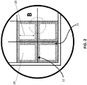
FIG. 2 is a zoomed-in view of Portion A of the filtration structure ofFIG. 1 according to an exemplary embodiment. -
FIG. 3 is a zoomed-in view of Portion B of the filtration structure ofFIG. 2 according to an exemplary embodiment. -
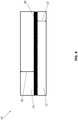
FIG. 4 is a simplified schematic diagram representing a filtration structure according to an exemplary embodiment. -
FIG. 5 is a simplified schematic diagram representing a carbon dioxide scrubber comprising a filtration structure according to an exemplary embodiment. - A detailed description of one or more embodiments of the disclosed apparatus and method are presented herein by way of exemplification and not limitation with reference to the Figures.
- Referring to
FIGS. 1-5 , afiltration structure 10 comprises asubstrate 12. For example, thesubstrate 12 can be a three-dimensional lattice formed from repeatinggeometric shapes 14. For example, thesubstrate 12 can be a single monolithic structure. For example, thesubstrate 12 can be formed via extrusion. - The
substrate 12 can comprise a conductive material. For example, thesubstrate 12 can comprise aluminum, aluminum alloy, copper, copper alloy, silver, gold, stainless steel, or combinations thereof. The repeatinggeometric shapes 14 of thesubstrate 12 can be, for example, polyhedral, rectangular, elliptical, triangular, annular, honeycombs, or combinations thereof. - A
thickness 22 of thesubstrate 12 can be about 0.025 millimeters to about 0.25 millimeters (about 0.001 inches to about 0.01 inches), for example, about 0.05 millimeters to about 0.18 millimeters (about 0.002 inches to about 0.007 inches), for example, about 0.05 millimeters to about 0.13 millimeters (about 0.002 inches to about 0.005 inches) (FIGS. 3 and4 ). - The
substrate 12 can comprisepassages 26 for fluid flow (FIG. 2 ). For example, gas, liquid, or a combination thereof, can flow through the open cell structure of the lattice. Adiameter 28 of thepassages 26 for fluid flow can be about 0.1 millimeters to about 1 millimeters (about 0.004 inches to about 0.04 inches), for example, about 0.55 millimeters to about 0.65 millimeters (about 0.022 inches to about 0.026 inches), for example, about 0.61 millimeters (about 0.024 inches). - The
substrate 12 can further comprise aparting sheet 16 which, for example, partitions thefiltration structure 10 into two or more beds (18, 20). For example, theparting sheet 16 can comprise metal, plastic, ceramic, a composite material, or combinations thereof. - A layer of
porous material 24 can be bonded over thesubstrate 12. For example, the layer ofporous material 24 can comprise polymer, silica gel, alumina, zeolites, carbon, or combinations thereof. For example, the layer ofporous material 24 can comprise polytetrafluoroethylene, polyvinylidene fluoride, polyethersulphone, poly (methyl methacrylate), polystyrene, polyethylene, pyrolyzed polyacrylonitrile, or combinations thereof. - A
thickness 30 of the layer ofporous material 24 can be about 0.01 millimeters to about 2 millimeters (about 0.0004 inches to about 0.079 inches), for example, about 0.35 millimeters to about 0.45 millimeters (about 0.014 inches to about 0.018 inches), for example, about 0.41 millimeters (about 0.016 inches) (FIGS. 3 and4 ). A diameter of thepores 32 in theporous material 24 can be about 0.02 micrometer to about 5 micrometers (about 7.87e-7 inches to about 0.0002 inches), for example, about 0.02 micrometers to about 0.5 micrometers (about 7.87e-7 inches to about 1.97e-5 inches), for example, about 0.05 micrometers (about 1.97e-6 inches). Pore size can vary widely and can be tailored to accommodate various liquid amines. - The layer of
porous material 24 can be bonded over thesubstrate 12 via, for example, suspension polymerization. The layer ofporous material 24 can also be welded to thesubstrate 12. Additionally, or alternatively, thefiltration structure 10 can further comprise a layer ofadhesive 34 between thesubstrate 12 and the layer of porous material 24 (FIG. 4 ). - A liquid amine can be retained within the
pores 32 of theporous material 24. For example, the liquid amines can be branched, linear, or combinations thereof. The liquid amine can be retained within thepores 32 via capillary forces. A density of liquid amine in thefiltration structure 10 can be about 0.25 milliliters to about 0.5 milliliters per cubic centimeter of the filtration structure 10 (i.e., about 25% to about 50% of a total filtration structure volume can be occupied by liquid amine), for example, about 0.3 milliliters to about 0.4 milliliters per cubic centimeter of the filtration structure 10 (i.e., about 30% to about 40% of a total filtration structure volume can be occupied by liquid amine), for example, about 0.37 milliliters per cubic centimeter of the filtration structure 10 (i.e., about 37% of a total filtration structure volume can be occupied by liquid amine). - A
carbon dioxide scrubber 36 can comprise thefiltration structure 10 described herein. For example, thefiltration structure 10 disclosed herein for use incarbon dioxide scrubbers 36 can be used to treat exhaust gases from industrial plants or from exhaled air in life support systems such as rebreathers or in spacecraft, submersible craft or airtight chambers. Thecarbon dioxide scrubbers 36 disclosed herein can also be used in controlled atmosphere storage and carbon capture as a means of combating global warming. Thecarbon dioxide scrubbers 36 disclosed herein can also be used for removal of carbon dioxide from the exhaust of coal and gas-fired power plants. - The
filtration structure 10 disclosed herein for use incarbon dioxide scrubbers 36 can improve thermal linkage between absorption and desorption beds, improve ventilation and overall efficiency, increases gas/amine contact surface area and cyclic capacity, and reduces pressure drop, power usage, total structural mass, and vacuum desorption pressures. For example, due to the monolithic design of the filtration structure and the improvements described above, thecarbon dioxide scrubber 36 disclosed herein can operate successfully without a retention screen. Elimination of the retention screen significantly reduces pressure drop, for example, during desorption phase, thus allowing for more efficient desorption. - The term "about" is intended to include the degree of error associated with measurement of the particular quantity based upon the equipment available at the time of filing the application.
- The terminology used herein is for the purpose of describing particular embodiments only and is not intended to be limiting of the present disclosure. As used herein, the singular forms "a", "an" and "the" are intended to include the plural forms as well, unless the context clearly indicates otherwise. It will be further understood that the terms "comprises" and/or "comprising," when used in this specification, specify the presence of stated features, integers, steps, operations, elements, and/or components (and encompasses "consist(s) of', "consisting of', "consist(s) essentially of' and "consisting essentially of'), but do not necessarily preclude the presence or addition of one or more other features, integers, steps, operations, element components, and/or groups thereof.
- While the present disclosure has been described with reference to an exemplary embodiment or embodiments, it will be understood by those skilled in the art that various changes may be made and equivalents may be substituted for elements thereof without departing from the scope of the present disclosure. In addition, many modifications may be made to adapt a particular situation or material to the teachings of the present disclosure without departing from the essential scope thereof. Therefore, it is intended that the present disclosure not be limited to the particular embodiment disclosed as the best mode contemplated for carrying out this present disclosure, but that the present disclosure will include all embodiments falling within the scope of the claims.
Claims (15)
- A filtration structure, comprising:a substrate (12), wherein the substrate is a three-dimensional lattice formed from repeating geometric shapes (14);a layer of porous material (24) bonded over the substrate; anda liquid amine retained within the pores of the porous material.
- The filtration structure of Claim 1, wherein the substrate is a single monolithic structure.
- The filtration structure of Claims 1 or 2, wherein the substrate comprises passages for the fluid flow of gas, liquid, or combinations thereof, and preferably wherein a diameter of the passages for the fluid flow of gas is about 0.55 millimeters to about 0.65 millimeters.
- The filtration structure of any preceding Claim, wherein the substrate comprises a conductive material, and preferably wherein the substrate comprises aluminum, aluminum alloy, copper, copper alloy, silver, gold, stainless steel, or combinations thereof.
- The filtration structure of any preceding Claim, wherein the repeating geometric shapes are polyhedral, rectangular, elliptical, triangular, annular, honeycombs, or combinations thereof.
- The filtration structure of any preceding Claim, wherein a thickness of the substrate is about 0.025 millimeters to about 0.25 millimeters.
- The filtration structure of any preceding Claim, wherein the layer of porous material comprises polymer, silica gel, alumina, zeolites, carbon, or combinations thereof, and preferably wherein the layer of porous material comprises polytetrafluoroethylene, polyvinylidene fluoride, polyethersulphone, poly(methyl methacrylate), polystyrene, polyethylene, pyrolyzed polyacrylonitrile, or combinations thereof.
- The filtration structure of any preceding Claim, wherein a thickness of the layer of porous material is about 0.01 millimeters to about 2 millimeters.; and/or
wherein a diameter of the pores in the porous material is about 0.02 micrometer to about 5 micrometers. - The filtration structure of any preceding Claim, wherein the layer of porous material is bonded over the substrate via suspension polymerization, welded to the substrate, or combinations thereof.
- The filtration structure of any preceding Claim, further comprising a layer of adhesive between the substrate and the layer of porous material.
- The filtration structure of any preceding Claim, wherein the liquid amines are branched, linear, or combinations thereof; and/or
wherein a density of liquid amine in the filtration structure is about 0.25 milliliters to about 0.5 milliliters per cubic centimeter of the filtration structure. - The filtration structure of any preceding Claim, wherein the substrate is formed via extrusion.
- The filtration structure of any preceding Claim, further comprising a parting sheet which partitions the filtration structure into two or more beds.
- A carbon dioxide scrubber comprising the filtration structure of Claim 1.
- The carbon dioxide scrubber of Claim 14, wherein the carbon dioxide scrubber does not comprise a retention screen.
Applications Claiming Priority (1)
| Application Number | Priority Date | Filing Date | Title |
|---|---|---|---|
| US16/382,646 US20200324246A1 (en) | 2019-04-12 | 2019-04-12 | Filtration structure for carbon dioxide scrubber |
Publications (1)
| Publication Number | Publication Date |
|---|---|
| EP3721969A1 true EP3721969A1 (en) | 2020-10-14 |
Family
ID=68732966
Family Applications (1)
| Application Number | Title | Priority Date | Filing Date |
|---|---|---|---|
| EP19212593.8A Pending EP3721969A1 (en) | 2019-04-12 | 2019-11-29 | Filtration structure for carbon dioxide scrubber |
Country Status (2)
| Country | Link |
|---|---|
| US (1) | US20200324246A1 (en) |
| EP (1) | EP3721969A1 (en) |
Cited By (1)
| Publication number | Priority date | Publication date | Assignee | Title |
|---|---|---|---|---|
| US20210370391A1 (en) * | 2018-03-28 | 2021-12-02 | Hamilton Sundstrand Corporation | Additively manufactured carbon dioxide scrubber |
Citations (5)
| Publication number | Priority date | Publication date | Assignee | Title |
|---|---|---|---|---|
| US20070261557A1 (en) * | 2006-05-11 | 2007-11-15 | Gadkaree Kishor P | Activated carbon honeycomb catalyst beds and methods for the use thereof |
| WO2010027929A1 (en) * | 2008-09-05 | 2010-03-11 | Alstom Technology Ltd | Novel solid materials and method for co2 removal from gas stream |
| US20100212495A1 (en) * | 2009-02-26 | 2010-08-26 | Kishor Purushottam Gadkaree | Sorbent Structure Applicable for Carbon Dioxide Capture |
| US20120216675A1 (en) * | 2011-02-28 | 2012-08-30 | Dayue David Jiang | Sorbent Articles for CO2 Capture |
| WO2013052637A2 (en) * | 2011-10-06 | 2013-04-11 | Basf Corporation | Methods of applying a sorbent coating on a substrate, a support, and/or a substrate coated with a support |
-
2019
- 2019-04-12 US US16/382,646 patent/US20200324246A1/en not_active Abandoned
- 2019-11-29 EP EP19212593.8A patent/EP3721969A1/en active Pending
Patent Citations (5)
| Publication number | Priority date | Publication date | Assignee | Title |
|---|---|---|---|---|
| US20070261557A1 (en) * | 2006-05-11 | 2007-11-15 | Gadkaree Kishor P | Activated carbon honeycomb catalyst beds and methods for the use thereof |
| WO2010027929A1 (en) * | 2008-09-05 | 2010-03-11 | Alstom Technology Ltd | Novel solid materials and method for co2 removal from gas stream |
| US20100212495A1 (en) * | 2009-02-26 | 2010-08-26 | Kishor Purushottam Gadkaree | Sorbent Structure Applicable for Carbon Dioxide Capture |
| US20120216675A1 (en) * | 2011-02-28 | 2012-08-30 | Dayue David Jiang | Sorbent Articles for CO2 Capture |
| WO2013052637A2 (en) * | 2011-10-06 | 2013-04-11 | Basf Corporation | Methods of applying a sorbent coating on a substrate, a support, and/or a substrate coated with a support |
Cited By (2)
| Publication number | Priority date | Publication date | Assignee | Title |
|---|---|---|---|---|
| US20210370391A1 (en) * | 2018-03-28 | 2021-12-02 | Hamilton Sundstrand Corporation | Additively manufactured carbon dioxide scrubber |
| US11772043B2 (en) * | 2018-03-28 | 2023-10-03 | Hamilton Sundstrand Corporation | Additively manufactured carbon dioxide scrubber |
Also Published As
| Publication number | Publication date |
|---|---|
| US20200324246A1 (en) | 2020-10-15 |
Similar Documents
| Publication | Publication Date | Title |
|---|---|---|
| JP4621575B2 (en) | Gas recovery method and apparatus | |
| Karoor et al. | Gas absorption studies in microporous hollow fiber membrane modules | |
| RU2424041C2 (en) | Removal of carbon dioxide from air | |
| US9616375B2 (en) | Capture of carbon dioxide (CO2) from air | |
| US9072987B2 (en) | Method and apparatus for desorption using a microporous membrane operated in wetted mode | |
| CN103958027A (en) | Methods of applying a sorbent coating on a substrate, a support, and/or a substrate coated with a support | |
| JP6964070B2 (en) | Acid gas separation film and acid gas separation method using it, acid gas separation module and acid gas separation device | |
| US5250091A (en) | Apparatus for separating a gas-water vapor mixture | |
| CN103879978A (en) | Online recovery and purification system for waste helium gas in aerostat | |
| JPH0699035A (en) | Method for separating and recovering carbon dioxide in waste gas | |
| US20200324246A1 (en) | Filtration structure for carbon dioxide scrubber | |
| Lee et al. | Integrated membrane contactor absorber/regeneration column process for CO2 capture with large scale module at various operating conditions | |
| US20250186931A1 (en) | Acid gas adsorption device | |
| JP2014133219A (en) | Gas removal device and gas removal method using the same | |
| Wójtowicz et al. | Monolithic trace-contaminant sorbents fabricated from 3D-printed polymer precursors | |
| US20240408847A1 (en) | Carbon capture systems and methods | |
| CN213956919U (en) | A 3D printing-based diffuser tube and atmospheric active gas collection device | |
| JPH06167B2 (en) | Oil removal device | |
| WO2023014710A1 (en) | Carbon dioxide capture system | |
| WO2022238474A1 (en) | Co2 adsorption apparatus | |
| JPH0699018A (en) | Membrane type polar gas separation device | |
| CN205055702U (en) | Filter element | |
| WO2025014872A2 (en) | Systems, methods, and apparatuses for carbon dioxide capture | |
| US12616931B2 (en) | High performance gas adsorbing material | |
| EP4520430A1 (en) | High performance gas adsorbing material |
Legal Events
| Date | Code | Title | Description |
|---|---|---|---|
| PUAI | Public reference made under article 153(3) epc to a published international application that has entered the european phase |
Free format text: ORIGINAL CODE: 0009012 |
|
| STAA | Information on the status of an ep patent application or granted ep patent |
Free format text: STATUS: THE APPLICATION HAS BEEN PUBLISHED |
|
| AK | Designated contracting states |
Kind code of ref document: A1 Designated state(s): AL AT BE BG CH CY CZ DE DK EE ES FI FR GB GR HR HU IE IS IT LI LT LU LV MC MK MT NL NO PL PT RO RS SE SI SK SM TR |
|
| AX | Request for extension of the european patent |
Extension state: BA ME |
|
| STAA | Information on the status of an ep patent application or granted ep patent |
Free format text: STATUS: REQUEST FOR EXAMINATION WAS MADE |
|
| 17P | Request for examination filed |
Effective date: 20210413 |
|
| RBV | Designated contracting states (corrected) |
Designated state(s): AL AT BE BG CH CY CZ DE DK EE ES FI FR GB GR HR HU IE IS IT LI LT LU LV MC MK MT NL NO PL PT RO RS SE SI SK SM TR |
|
| STAA | Information on the status of an ep patent application or granted ep patent |
Free format text: STATUS: EXAMINATION IS IN PROGRESS |
|
| 17Q | First examination report despatched |
Effective date: 20230103 |