EP3721963B1 - Filter assembly for water purifier - Google Patents
Filter assembly for water purifier Download PDFInfo
- Publication number
- EP3721963B1 EP3721963B1 EP20168666.4A EP20168666A EP3721963B1 EP 3721963 B1 EP3721963 B1 EP 3721963B1 EP 20168666 A EP20168666 A EP 20168666A EP 3721963 B1 EP3721963 B1 EP 3721963B1
- Authority
- EP
- European Patent Office
- Prior art keywords
- filter
- guide
- stopper
- pusher
- water purifier
- Prior art date
- Legal status (The legal status is an assumption and is not a legal conclusion. Google has not performed a legal analysis and makes no representation as to the accuracy of the status listed.)
- Active
Links
Images




Classifications
-
- B—PERFORMING OPERATIONS; TRANSPORTING
- B01—PHYSICAL OR CHEMICAL PROCESSES OR APPARATUS IN GENERAL
- B01D—SEPARATION
- B01D35/00—Filtering devices having features not specifically covered by groups B01D24/00 - B01D33/00, or for applications not specifically covered by groups B01D24/00 - B01D33/00; Auxiliary devices for filtration; Filter housing constructions
- B01D35/30—Filter housing constructions
- B01D35/306—Filter mounting adapter
-
- C—CHEMISTRY; METALLURGY
- C02—TREATMENT OF WATER, WASTE WATER, SEWAGE, OR SLUDGE
- C02F—TREATMENT OF WATER, WASTE WATER, SEWAGE, OR SLUDGE
- C02F1/00—Treatment of water, waste water, or sewage
- C02F1/001—Processes for the treatment of water whereby the filtration technique is of importance
- C02F1/003—Processes for the treatment of water whereby the filtration technique is of importance using household-type filters for producing potable water, e.g. pitchers, bottles, faucet mounted devices
-
- B—PERFORMING OPERATIONS; TRANSPORTING
- B01—PHYSICAL OR CHEMICAL PROCESSES OR APPARATUS IN GENERAL
- B01D—SEPARATION
- B01D27/00—Cartridge filters of the throw-away type
- B01D27/02—Cartridge filters of the throw-away type with cartridges made from a mass of loose granular or fibrous material
-
- B—PERFORMING OPERATIONS; TRANSPORTING
- B01—PHYSICAL OR CHEMICAL PROCESSES OR APPARATUS IN GENERAL
- B01D—SEPARATION
- B01D29/00—Filters with filtering elements stationary during filtration, e.g. pressure or suction filters, not covered by groups B01D24/00 - B01D27/00; Filtering elements therefor
- B01D29/11—Filters with filtering elements stationary during filtration, e.g. pressure or suction filters, not covered by groups B01D24/00 - B01D27/00; Filtering elements therefor with bag, cage, hose, tube, sleeve or like filtering elements
- B01D29/13—Supported filter elements
-
- B—PERFORMING OPERATIONS; TRANSPORTING
- B01—PHYSICAL OR CHEMICAL PROCESSES OR APPARATUS IN GENERAL
- B01D—SEPARATION
- B01D2201/00—Details relating to filtering apparatus
- B01D2201/04—Supports for the filtering elements
- B01D2201/0415—Details of supporting structures
- B01D2201/0423—Details of supporting structures not in the inner side of the cylindrical filtering elements
-
- B—PERFORMING OPERATIONS; TRANSPORTING
- B01—PHYSICAL OR CHEMICAL PROCESSES OR APPARATUS IN GENERAL
- B01D—SEPARATION
- B01D2201/00—Details relating to filtering apparatus
- B01D2201/30—Filter housing constructions
- B01D2201/301—Details of removable closures, lids, caps, filter heads
- B01D2201/302—Details of removable closures, lids, caps, filter heads having inlet or outlet ports
-
- B—PERFORMING OPERATIONS; TRANSPORTING
- B01—PHYSICAL OR CHEMICAL PROCESSES OR APPARATUS IN GENERAL
- B01D—SEPARATION
- B01D2201/00—Details relating to filtering apparatus
- B01D2201/30—Filter housing constructions
- B01D2201/301—Details of removable closures, lids, caps, filter heads
- B01D2201/302—Details of removable closures, lids, caps, filter heads having inlet or outlet ports
- B01D2201/303—Details of removable closures, lids, caps, filter heads having inlet or outlet ports not arranged concentrically
-
- B—PERFORMING OPERATIONS; TRANSPORTING
- B01—PHYSICAL OR CHEMICAL PROCESSES OR APPARATUS IN GENERAL
- B01D—SEPARATION
- B01D2201/00—Details relating to filtering apparatus
- B01D2201/34—Seals or gaskets for filtering elements
- B01D2201/347—Radial sealings
-
- B—PERFORMING OPERATIONS; TRANSPORTING
- B01—PHYSICAL OR CHEMICAL PROCESSES OR APPARATUS IN GENERAL
- B01D—SEPARATION
- B01D2201/00—Details relating to filtering apparatus
- B01D2201/40—Special measures for connecting different parts of the filter
- B01D2201/4007—Use of cam or ramp systems
-
- B—PERFORMING OPERATIONS; TRANSPORTING
- B01—PHYSICAL OR CHEMICAL PROCESSES OR APPARATUS IN GENERAL
- B01D—SEPARATION
- B01D2201/00—Details relating to filtering apparatus
- B01D2201/40—Special measures for connecting different parts of the filter
- B01D2201/4023—Means for connecting filter housings to supports
-
- B—PERFORMING OPERATIONS; TRANSPORTING
- B01—PHYSICAL OR CHEMICAL PROCESSES OR APPARATUS IN GENERAL
- B01D—SEPARATION
- B01D2201/00—Details relating to filtering apparatus
- B01D2201/40—Special measures for connecting different parts of the filter
- B01D2201/4046—Means for avoiding false mounting of different parts
-
- B—PERFORMING OPERATIONS; TRANSPORTING
- B01—PHYSICAL OR CHEMICAL PROCESSES OR APPARATUS IN GENERAL
- B01D—SEPARATION
- B01D2201/00—Details relating to filtering apparatus
- B01D2201/40—Special measures for connecting different parts of the filter
- B01D2201/4046—Means for avoiding false mounting of different parts
- B01D2201/4061—Means for avoiding false mounting of different parts between a cartridge and a filter head or manifold
-
- B—PERFORMING OPERATIONS; TRANSPORTING
- B01—PHYSICAL OR CHEMICAL PROCESSES OR APPARATUS IN GENERAL
- B01D—SEPARATION
- B01D2201/00—Details relating to filtering apparatus
- B01D2201/40—Special measures for connecting different parts of the filter
- B01D2201/4076—Anti-rotational means
Definitions
- the disclosure relates to a filter assembly for a water purifier configured to easily assemble and disassemble a filter.
- water purifiers are widely used for home use as a device for filtering water to remove impurities.
- Water purifiers are classified according to the purpose, configuration, water purification method, etc., and the natural filtration type and the direct filtration type water purifiers mainly used may employ a purification method using a filter, and thus these are referred to as filter type water purifiers, for convenience.
- a filter type water purifier provides purified water through a process of water input, filtration, adsorption, main filtration and water output.
- a filtration filter is used in the filtration process in which raw water such as tap water is input and impurities contained in the input tap water is filtered out.
- the filter needs to be replaced every predetermined period.
- WO 2010/033470 A2 discloses a filter cartridge for a filtration system including an outer shell having a first end and a second end, an inlet and an outlet located on the first end, and at least one cam track located on the outer shell.
- KR 2012 0055445 A discloses a filter tank for a water purifier capable of locking and unlocking with one touch, and a water purifier using the same.
- a filter assembly for a water purifier is provided as defined in the appended claims.
- the lock may further include a housing in which the pusher is received to be linearly movable.
- the housing may include an inlet tube through which water is introduced to the filter when the filter is inserted into the filter holder, an outlet tube through which the introduced water is filtered by the filter and discharged from the filter when the filter is inserted into the filter holder, a plurality of support protrusions on which one side of the elastic member is supported, and a plurality of cam holes to which the cam is coupled.
- the filter may include an insert inserted into the filter holder, an inlet connected to the inlet tube, an outlet connected to the outlet tube, and a positioning hole configured to select a position, in which the filter is coupled to the filter holder, so as to connect the inlet to the inlet tube and to connect the outlet to the outlet tube.
- the filter holder may include a fixing part to which the insert is inserted and attachable to or detachable from the filter holder, a first connection tube configured to connect the inlet tube to the inlet, a second connection tube configured to connect the outlet tube to the outlet; an O-ring respectively provided on an outer circumferential surface of the first connection tube inserted into the inlet, so as to seal between the inlet and the first connection tube and on an outer circumferential surface of the second connection tube inserted into the outlet, so as to seal between the outlet and the second connection tube, a positioning protrusion inserted into the positioning hole, and a plurality of guide coupling holes coupled to the guide.
- the fixing part may be elastically deformable and thus when the fixing part is received in an inside of the cam, the filter may be locked to the fixing part, and when the fixing part is exposed to an outside of the cam, the filter may be released from the fixing part.
- the guide may include a plurality of filter holder coupling holes coupled to the filter holder, a contact part in contact with the stopper to linearly move the stopper, a plurality of first guide protrusions formed on an inner circumferential surface of the guide to guide the linear movement of the guide, and a plurality of second guide protrusions formed on an outer circumferential surface of the guide to guide the linear movement of the guide.
- the contact part may be formed by a plurality of uneven parts including an inclined surface.
- the pusher may include a plurality of support grooves on which the other side of the elastic member is supported, a pressing part in contact with the stopper to press the stopper so as to allow the stopper to be linearly moved in the direction opposite to the direction into which the filter is inserted, and a plurality of guide parts configured to guide linear movement of the plurality of first guide protrusions.
- the stopper may include a pressed surface pressed by the pressing part, a plurality of guide bars configured to rotate and linearly move the stopper by being guided by the cam, and an inclined part formed at an end of the guide bar so as to be in contact with the contact part and provided with an inclined surface having an angle corresponding to the inclined surface of the contact part.
- the cam may include a plurality of housing coupling holes coupled to the plurality of cam coupling holes, a pusher guide received in the inside of the pusher to guide the pusher so as to allow the pusher to linearly moved, a plurality of guide grooves formed on an inner circumferential surface of the cam to guide linear movement of the plurality of guide bars, and a plurality of rotation guides formed among each of the plurality of guide grooves to guide the plurality of guide bars so as to allow the stopper to be rotated.
- Each of the plurality of rotation guides may include a plurality of rotating inclined surfaces provided with an inclined surface having an angle corresponding to the inclined surface formed on the contact part and the inclined part, the plurality of rotating inclined surfaces configured to guide the stopper to allow the stopper to be rotated toward one direction.
- the plurality of rotating inclined surfaces may include a first rotating inclined surface connected to the guide groove in a direction in which the stopper is rotated, and a second rotating inclined surface spaced apart from the first rotating inclined surface in the direction in which the stopper is rotated.
- Each of the plurality of rotation guides may include a movement stopper formed between the first rotating inclined surface and the second rotating inclined surface so as to stop the rotation of the stopper rotated along the first rotating inclined surface and so as to prevent the linear movement of the stopper toward the direction opposite to the direction into which the filter is inserted.
- the movement stopper may include a guide groove part configured to guide the linear movement of the plurality of second guide protrusions, together with the plurality of guide grooves.
- a filter assembly for a water purifier includes a filter holder into which a part of the filter is inserted, and a lock mounted to the filter holder, and configured to lock the filter to the filter holder based on movement of the filter holder in a direction into which the filter is inserted and configured to release the filter from the filter holder based on movement of the filter holder in a direction opposite to the direction into which the filter is inserted.
- the lock includes a guide configured to be linearly movable together with the filter holder to transmit a force in the direction into which the filter is inserted, a pusher including an elastic member, and the pusher, and configured to transmit a force in the direction opposite to the direction, into which the filter is inserted, by an elastic member, a stopper rotatably received in the pusher to be arranged between the pusher and the guide, and configured to lock the filter to the filter holder or release the filter from the filter holder by being linearly moved by the guide and the pusher, and a cam configured to guide rotation and linear movement of the stopper.
- the lock may further include a housing to which the cam is coupled and in which the pusher is received to be linearly movable.
- the housing may include an inlet tube through which water is introduced to the filter when the filter is inserted into the filter holder, and an outlet tube through which the introduced water is filtered by the filter and discharged from the filter when the filter is inserted into the filter holder
- the filter may include an inlet connected to the inlet tube, and an outlet connected to the outlet tube
- the filter holder may include a first connection tube configured to connect the inlet tube to the inlet, and a second connection tube configured to connect the outlet tube to the outlet.
- the cam may include a plurality of guide grooves formed on an inner circumferential surface of the cam to guide linear movement of the stopper, and a plurality of rotation guides formed among the plurality of guide grooves to guide rotation of the stopper.
- the filter may include a fixing groove formed to have a groove shape along an outer circumferential surface of thereof to be inserted and fixed into the filter holder, and the filter holder may include a fixing protrusion fixed to the fixing groove to allow the filter to be attachable to or detachable from the filter holder.
- first, second, third, etc. may be used herein to describe various elements, but elements are not limited by these terms. These terms are only used to distinguish one element from another element. For example, without departing from the scope of the disclosure, a first element may be termed as a second element, and a second element may be termed as a first element.
- the term of "and / or" includes a plurality of combinations of relevant items or any one item among a plurality of relevant items.
- front end In the following detailed description, the terms of “front end”, “rear end”, “upper portion”, “lower portion”, “upper end”, “lower end” and the like may be defined by the drawings, but the shape and the location of the component is not limited by the term.
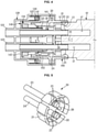
- FIG. 1 is a perspective view illustrating a state in which a filter is locked to a filter holder according to an embodiment of the disclosure
- FIG. 2 is a perspective view illustrating a state in which the filter is separated from the filter holder by being released from the filter holder according to an embodiment of the disclosure.
- a filter assembly may include a filter 10, a filter holder 20 to which the filter 10 is attachable to or detachable from the filter holder 20, and a locking device 100 configured to lock and release the filter 10 to and from the filter holder 20.
- the filter 10 may include an insert 11 inserted into the filter holder 20, an inlet 15 through which raw water is introduced, an outlet 17 through which the introduced raw water is filtered by the filter 10 and then discharged, and a positioning hole 19 configured to select a position in which the filter 10 is coupled to the filter holder 20.
- the insert 11 may include a fixing groove 13 formed to have a groove shape along an outer circumferential surface of the insert 11 so that the insert 11 is inserted and fixed into the filter holder 20.
- the filter holder 20 may include a fixing protrusion 22 fixed to the fixing groove 13 to allow the filter 10 to be attachable to or detachable from the filter holder 20 (refer to FIG. 4 ).
- a positioning protrusion 26 of the filter holder 20 to be described later may be inserted into the positioning hole 19.
- the positioning hole 19 may select a position, in which the filter 10 is coupled to the filter holder 20, so that the inlet 15 and the outlet 17 are respectively connected to an inlet tube 121 and an outlet tube 123 when the filter 10 is fixed to the filter holder 20.
- the inlet 15 of the filter 10 may be connected to a first connection tube 23 of the filter holder 20 to insert the positioning protrusion 26 of the filter holder 20 into the positioning hole 19 of the filter 10.
- the outlet 17 of the filter 10 may be connected to a second connection tube 24 of the filter holder 20. Therefore, the inlet 15 of the filter 10 may be connected to the inlet tube 121 of the housing 120 through the first connection tube 23.
- the outlet 17 of the filter 10 may be connected to the outlet tube 123 of the housing 120 through the second connection tube 24 (refer to FIG. 4 ).
- FIG. 3 is an exploded perspective view of the filter holder and a locking device coupled to the filter holder according to an embodiment of the disclosure
- FIG. 4 is a cross-sectional view illustrating a state in which the filter is locked to the filter holder according to an embodiment of the disclosure
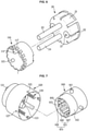
- FIG. 5 is a view illustrating a state in which the filter holder is coupled to a guide according to an embodiment of the disclosure
- FIG. 6 is a view illustrating the filter holder of FIG. 5 at a different angle
- FIG. 7 is a view illustrating a state in which a housing and a cam is coupled to each other according to an embodiment of the disclosure
- FIG. 8 is a view illustrating a state in which a pusher is received in the housing according to an embodiment of the disclosure
- FIG. 9 is a view illustrating a state in which a first guide protrusion of the guide is guided by a guide portion of the pusher according to an embodiment of the disclosure.
- the locking device 100 configured to lock and release the filter 10 to and from the filter holder 20 may be mounted to the filter holder 20.
- the filter holder 20 may include a fixing portion 21 into which the insert 11 of the filter 10 is inserted and attachable to or detachable from the filter holder, the first connection tube 23 configured to connect the inlet tube 121 of the housing 120 to the inlet 15 of the filter 10, the second connection tube 24 configured to connect the outlet tube 123 of the housing 120 to the outlet 17 of the filter 10, an O-ring 25 provided on an outer circumferential surface of the first connection tube 23 inserted into the inlet 15, so as to seal between the inlet 15 and the first connection tube 23, and provided on an outer circumferential surface of the second connection tube 25 inserted into the outlet 17, so as to seal between the outlet 17 and the second connection tube 25, the positioning protrusion 26 inserted into the positioning hole 19, and a plurality of guide coupling holes 27 coupled to a guide 110.
- the fixing portion 21 may include a fixing protrusion 22 fixed to the fixing groove 13 of the filter 10 that is inserted and fixed into the filter holder 20.
- the fixing portion 21 may be elastically deformable. Therefore, when the fixing portion 21 is received in the inside of a cam 160, the filter 10 may be locked to the fixing portion 21, and when the fixing portion 21 is exposed to the outside of the cam 160, the filter 10 may be released from the fixing portion 21.
- the O-ring 25 may be provided in plural.
- the locking device 100 may include the guide 110 coupled to the filter holder 20, the housing 120 including the inlet tube 121 and the outlet tube 123, and a plurality of elastic members 130 having one side thereof supported by the housing 120, a pusher 140 on which the other side of the plurality of elastic members 130 is supported, a stopper 150 arranged between the pusher 140 and the guide 110 so as to be rotatably received in the inside of the pusher 140, and the cam 160 configured to guide rotation and linear movement of the stopper 150.
- the guide 110 may be coupled to the filter holder 20 and then moved linearly with the filter holder 20.
- the guide 110 may be replaced in the inside of the cam 160 and linearly moved.
- the guide 110 may be linearly moved in a direction, into which the filter 10 is inserted, together with the filter holder 20 and thus the guide 110 may transmit a force in the direction into which the filter 10 is inserted.
- the guide 110 may include a plurality of filter holder coupling holes 111 coupled to the filter holder 20, a contact portion 113 in contact with the stopper 150 to linearly move the stopper 150, a plurality of first guide protrusions 115 formed on an inner circumferential surface of the guide 110 to guide the linear movement of the guide 110, and a plurality of second guide protrusions 117 formed on an outer circumferential surface of the guide 110 to guide the linear movement of the guide 110.
- the contact portion 113 may be formed by a plurality of uneven portions having an inclined surface.
- the contact portion 113 may have a triangular shape, but the shape of the contact portion 113 is not limited thereto.
- the inclined surface of the contact portion 113 may be in contact with an inclined portion 155 of the stopper 150.
- the filter 10 may be inserted into the filter holder 20 and the filter holder 20 may be pushed in the direction into which the filter 10 is inserted.
- the guide 110 may be linearly moved in the direction, into which the filter 10 is inserted, together with the filter holder 20.
- the guide 110 which is linearly moved in the direction into which the filter 10 is inserted, may transmit a force in the direction, into which the filter 10 is inserted, to the stopper 150.
- the stopper 150 may also be linearly moved in the direction into which the filter 10 is inserted.
- the plurality of first guide protrusions 115 formed on the inner circumferential surface of the guide 110 may be guided by a guide portion 145 of the pusher 140 so as to linearly move the guide 110.
- the plurality of second guide protrusions 117 formed on the outer circumferential surface of the guide 110 may be guided by a guide groove 163 and a guide groove portion 169 of the cam 160 so as to linearly move the guide 110.
- the housing 120 may include the inlet tube 121 through which raw water is introduced, the outlet tube 123 through which the introduced raw water is filtered by the filter 10 and then discharged, a plurality of support protrusions 125 on which one side of the plurality of elastic members 130 is supported, and a plurality of cam coupling holes 127 to which the cam 160 is coupled.
- the inlet tube 121 may be connected to the inlet 15 of the filter 10 through the first connection tube 23 of the filter holder 20.
- the outlet tube 123 may be connected to the outlet 17 of the filter 10 through the second connection tube 24 of the filter holder 20.
- the raw water introduced into the inlet tube 121 may be introduced into the inlet 15 of the filter 10 through the first connection tube 23 and filtered, the purified water that is filtered may be delivered to the second connection tube 24 through the outlet 17, and then the purified water delivered to the second connection tube 24 may be discharged through the outlet tube 123.
- the elastic member 130 may be provided in plural and one side thereof may be supported by the support protrusion 125 of the housing 120, and the other side thereof may be supported by a support groove 141 of the pusher 140. Because the housing 120, on which one side of the elastic member 130 is supported, is fixed, the pusher 140, on which the other side of the elastic member 130 is supported, may transmit the force in a direction opposite to the direction, into which the filter 10 is inserted, by the elastic force of the elastic member 130. The force that is transmitted to the direction opposite to the direction, into which the filter 10 is inserted may linearly move the stopper 150, which is in contact with the pusher 140, to the direction opposite to the direction into which the filter 10 is inserted.
- the pusher 140 may include the plurality of support grooves 141 on which the other side of the plurality of elastic members 130 is supported, a pressing portion 143 in contact with the stopper 150 so as to linearly move the stopper 150 toward the direction opposite to the direction into which the filter 10 is inserted, and a plurality of guide portions 145 configured to guide the plurality of guide protrusions 115 so as to linearly move the guide 110.
- the pusher 140 may be linearly moved in the direction opposite to the direction, into which the filter 10 is inserted, by the elastic force of the elastic member 130.
- the stopper 150 which is in contact with the pusher 140 may be pressed by the pusher 140 which is linearly moved in the direction opposite to the direction into which the filter 10 is inserted, and thus the stopper 150 may be linearly moved in the direction opposite to the direction into which the filter 10 is inserted.
- the stopper 150 may be rotatably received in the inside of the pusher 140 to be arranged between the pusher 140 and the guide 110.
- the stopper 150 may include a pressed surface 151 pressed by the pressing portion 143 of the pusher 140, a plurality of guide bars 153 guided by the cam 160 to rotate and linearly move the stopper 150, and an inclined portion 155 formed at the end of the guide bar 155 so as to be in contact with the contact portion 113 of the guide 110.
- the pressed surface 151 may be pressed by the pressing portion 143 of the pusher 140, which is moved linearly in the direction opposite to the direction into which the filter 10 is inserted, and thus the pressed surface 151 may be linearly moved in the direction opposite to the direction into which the filter 10 is inserted.
- the plurality of guide bars 153 may be linearly moved by being guided by the guide grooves 163 of the cam 160. In addition, the plurality of guide bars 153 may be guided and rotated by a rotation guide 164 of the cam 160.
- the inclined portion 155 formed at the end of the guide bar 153 may include an inclined surface having an angle corresponding to the inclined surface of the contact portion 113.
- the stopper 150 may be rotatably moved in one direction by the rotation guide 164 of the cam 160.
- the stopper 150 arranged between the pusher 140 and the guide 110 may be linearly moved in the direction, into which the filter 10 is inserted, by the guide 110, and the stopper 150 may be linearly moved in the direction opposite to the direction, into which the filter 10 is inserted, by the pusher 140.
- the cam 160 may guide rotation and linear movement of the stopper 150 so as to lock and release the filter 10 to and from the filter holder 20.
- the cam 160 may include the plurality of housing coupling holes 161 coupled to the housing 120, a pusher guide 162 received in the inside of the pusher 140 to guide the pusher 140 to move linearly the pusher 140, the plurality of guide grooves 163 formed on the inner circumferential surface of the cam 160 to guide the linear movement of the plurality of guide bars 153, and the plurality of rotation guides 164 formed among the plurality of guide grooves 163 to guide the plurality of guide bars 153 so as to rotate the stopper 150.
- Each of the plurality of rotation guides 164 may include a pair of rotating inclined surfaces 165 formed to have an inclined surface having an angle corresponding to the inclined surface formed on the contact portion 113 of the guide 110 and the inclined portion 155 of the stopper 150.
- the pair of rotating inclined surfaces 165 may guide the stopper 150 to allow the stopper 150 to be rotated toward one direction through the inclined surface.
- the pair of rotating inclined surfaces 165 may include a first rotating inclined surface 166 connected to the guide groove 163 in a direction in which the stopper 150 is rotated, and a second rotating inclined surface 167 spaced apart from the first rotating inclined surface 166 in the direction in which the stopper 150 is rotated
- Each of the plurality of rotation guides 164 may include a movement stopper 168 formed between the first rotating inclined surface 166 and the second rotating inclined surface 167.
- the movement stopper 168 may stop the rotation of the stopper 150 rotated along the first rotating inclined surface 166.
- the movement stopper 168 may prevent the linear movement of the stopper 150 toward the direction opposite to the direction into which the filter 10 is inserted.
- the movement stopper 168 may include the guide groove portion 169 configured to guide the linear movement of the plurality of second guide protrusions 117 formed in the guide 110, together with the plurality of guide grooves 163 (refer to FIG. 19 ).
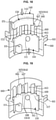
- FIG. 10 is a view illustrating of the locking device in a state in which the filter is released from the filter holder according to an embodiment of the disclosure
- FIG. 11 is a view illustrating a state in which the filter inserted to the filter holder is pressed to move the guide to a direction, into which the filter is inserted, so as to lock the filter to the filter holder based on FIG. 10
- FIG. 12 is a view illustrating a state in which a stopper is rotated to prevent liner movement in a direction opposite to the direction, into which the filter is inserted, and thus the filter is locked to the filter holder based on FIG. 11
- FIG. 13 is a view illustrating a state in which a configuration of the guide of FIG. 12 is omitted
- FIG. 14 a view illustrating a state in which the filter is pressed to move the guide toward the direction, into which the filter is inserted, so as to release the filter from the filter holder based on FIG. 12
- FIG. 15 is a view illustrating a state in which the configuration of the guide of FIG. 14 is omitted
- FIG. 16 is a view illustrating a state in which the stopper is rotated along an inclined surface based on FIG. 15
- FIG. 17 is a view illustrating a state in which the configuration of the guide of FIG. 16 is omitted
- FIG. 15 is a view illustrating a state in which the configuration of the guide of FIG. 14 is omitted
- FIG. 16 is a view illustrating a state in which the stopper is rotated along an inclined surface based on FIG. 15
- FIG. 17 is a view illustrating a state in which the configuration of the guide of FIG. 16 is omitted
- FIG. 18 is a view illustrating a state in which the stopper is pressed by the pusher to be linearly moved in the direction opposite to the direction, into which the filter is inserted, and thus a guide bar is inserted into a guide groove based on FIG. 16
- FIG. 19 is a view illustrating a state in which a configuration of the stopper and the pusher of FIG. 18 are omitted.
- an upward direction indicates a direction in which the filter 10 is inserted into the filter holder 20.
- the direction in which the filter 10 is inserted into the filter holder 20 is illustrated as the upward direction
- a direction opposite to the direction in which the filter 10 is inserted into the filter holder 20 is illustrated as a downward direction.
- the plurality of guide bars 153 may be inserted to the plurality of guide grooves163 (refer to FIG. 4 ).
- the filter holder 20 may be linearly moved in the direction into which the filter 10 is inserted.
- the guide 110 coupled to the filter holder 20 may also be linearly moved in the direction into which the filter 10 is inserted.
- the stopper 150 and the pusher 140 may also be linearly moved in the direction, into which the filter 10 is inserted, by the guide 110.
- the guide bar 153 of the stopper 150 may be separated from the guide groove 163 of the cam 160.
- the fixing portion 21 of the filter holder 20 may be in a state of being received in the cam 160 (refer to FIG. 4 ).
- the guide bar 153 of the stopper 150 When the guide bar 153 of the stopper 150 is separated from the guide groove 163 of the cam 160, the guide bar 153 may be rotated along the first rotating inclined surface 166 of the cam 160 and the inclined surface formed on the contact portion 113 of the guide 110 in a state in which the inclined portion 155 of the stopper 150 is in contact with the first rotating inclined surface 166 of the cam 160 and the inclined surface formed on the contact portion 113 of the guide 110, as illustrated in FIGS. 12 and 13 . In this case, the stopper 150 and the pusher 140 may be rotated and at the same time linearly moved partially in the downward direction. The guide 110 may also be moved downward by the stopper 150 moved downward.
- the guide bar 153 may be caught by the movement stopper 168 of the cam 160, thereby preventing rotation and linear movement thereof. Therefore, the fixing portion 21 of the filter holder 20 may be maintained in a state of being received in the inside of the cam 160 and thus the filer 10 may be locked to the filter holder 20 (refer to FIG. 4 ).
- the guide 110 When the filter 10 is pushed to be released from the filter holder 20 as illustrated in FIGS. 14 and 15 , the guide 110 may be linearly moved in the upward direction. When the guide 110 is moved upward, the stopper 150 and the pusher 140 may also be linearly moved upward by the guide 110. When the stopper 150 is linearly moved upward, the guide bar 153 of the stopper 150 may be separated from the movement stopper 168 (refer to FIG. 4 ).
- the guide bar 153 of the stopper 150 When the guide bar 153 of the stopper 150 is separated from the movement stopper 168, the guide bar 153 may be rotated along the second rotating inclined surface 167 of the cam 160 and the inclined surface formed on the contact portion 113 of the guide 110 in a state in which the inclined portion 155 of the stopper 150 is in contact with the first rotating inclined surface 166 of the cam 160 and the inclined surface formed on the contact portion 113 of the guide 110, as illustrated in FIGS. 17 and 18 . In this case, the stopper 150 and the pusher 140 may be rotated and at the same time linearly moved partially in the downward direction. The guide 110 may also be moved downward by the stopper 150 moved downward. The guide bar 153 of the stopper 150 may be moved to a position of being inserted into the guide groove 163.
- the stopper 150 and the pusher 140 are rotated and at the same time linearly moved partially in the downward direction and thus the guide bar 153 of the stopper 150 is moved to a position of being inserted into the guide groove 163, the stopper 150 may be linearly moved downward by the pusher 140 pressed by the elastic member 130, as illustrated in FIGS. 18 and 19 .
- the stopper 150 is linearly moved downward, the guide bar 153 may be inserted into the guide groove 163.
- the fixing portion 21 of the filter holder 20 may be exposed to the outside of the cam 160.
- the filter 10 When the fixing portion 21 of the filter holder 20 is exposed to the outside of the cam 160, the filter 10 may be released from the filter holder 20. When the filter 10 is released from the filter holder 20, the filter 10 may be separated from the filter holder 20 (refer to FIG. 4 ).
- the filter 10 may be locked to and released from the filter holder 20 by only an operation of pressing the filter 10, and thus the filter 10 may be easily assembled and disassembled.
- the assembly and disassembly of the filter may be easy, and thus the production speed and the working speed for the replacement of the filter may be improved.
Landscapes
- Chemical & Material Sciences (AREA)
- Chemical Kinetics & Catalysis (AREA)
- Life Sciences & Earth Sciences (AREA)
- Hydrology & Water Resources (AREA)
- Engineering & Computer Science (AREA)
- Environmental & Geological Engineering (AREA)
- Water Supply & Treatment (AREA)
- Organic Chemistry (AREA)
- Water Treatment By Sorption (AREA)
- Separation Using Semi-Permeable Membranes (AREA)
Description
- The disclosure relates to a filter assembly for a water purifier configured to easily assemble and disassemble a filter.
- In general, water purifiers are widely used for home use as a device for filtering water to remove impurities.
- Water purifiers are classified according to the purpose, configuration, water purification method, etc., and the natural filtration type and the direct filtration type water purifiers mainly used may employ a purification method using a filter, and thus these are referred to as filter type water purifiers, for convenience.
- In general, a filter type water purifier provides purified water through a process of water input, filtration, adsorption, main filtration and water output.
- Accordingly, as for the filter type water purifier, a filtration filter is used in the filtration process in which raw water such as tap water is input and impurities contained in the input tap water is filtered out.
- Therefore, because the performance of the water purifier depends on proper maintenance of the filter, the filter needs to be replaced every predetermined period.
-
WO 2010/033470 A2 discloses a filter cartridge for a filtration system including an outer shell having a first end and a second end, an inlet and an outlet located on the first end, and at least one cam track located on the outer shell. -
KR 2012 0055445 A - Therefore, it is an aspect of the disclosure to provide a filter assembly for a water purifier capable of easily assembling and disassembling a filter.
- Additional aspects of the disclosure will be set forth in part in the description which follows and, in part, will be apparent from the description, or may be learned by practice of the disclosure.
- In accordance with an embodiment of the disclosure, a filter assembly for a water purifier is provided as defined in the appended claims.
- The lock may further include a housing in which the pusher is received to be linearly movable.
- The housing may include an inlet tube through which water is introduced to the filter when the filter is inserted into the filter holder, an outlet tube through which the introduced water is filtered by the filter and discharged from the filter when the filter is inserted into the filter holder, a plurality of support protrusions on which one side of the elastic member is supported, and a plurality of cam holes to which the cam is coupled.
- The filter may include an insert inserted into the filter holder, an inlet connected to the inlet tube, an outlet connected to the outlet tube, and a positioning hole configured to select a position, in which the filter is coupled to the filter holder, so as to connect the inlet to the inlet tube and to connect the outlet to the outlet tube.
- The filter holder may include a fixing part to which the insert is inserted and attachable to or detachable from the filter holder, a first connection tube configured to connect the inlet tube to the inlet, a second connection tube configured to connect the outlet tube to the outlet; an O-ring respectively provided on an outer circumferential surface of the first connection tube inserted into the inlet, so as to seal between the inlet and the first connection tube and on an outer circumferential surface of the second connection tube inserted into the outlet, so as to seal between the outlet and the second connection tube, a positioning protrusion inserted into the positioning hole, and a plurality of guide coupling holes coupled to the guide.
- The fixing part may be elastically deformable and thus when the fixing part is received in an inside of the cam, the filter may be locked to the fixing part, and when the fixing part is exposed to an outside of the cam, the filter may be released from the fixing part.
- The guide may include a plurality of filter holder coupling holes coupled to the filter holder, a contact part in contact with the stopper to linearly move the stopper, a plurality of first guide protrusions formed on an inner circumferential surface of the guide to guide the linear movement of the guide, and a plurality of second guide protrusions formed on an outer circumferential surface of the guide to guide the linear movement of the guide.
- The contact part may be formed by a plurality of uneven parts including an inclined surface.
- The pusher may include a plurality of support grooves on which the other side of the elastic member is supported, a pressing part in contact with the stopper to press the stopper so as to allow the stopper to be linearly moved in the direction opposite to the direction into which the filter is inserted, and a plurality of guide parts configured to guide linear movement of the plurality of first guide protrusions.
- The stopper may include a pressed surface pressed by the pressing part, a plurality of guide bars configured to rotate and linearly move the stopper by being guided by the cam, and an inclined part formed at an end of the guide bar so as to be in contact with the contact part and provided with an inclined surface having an angle corresponding to the inclined surface of the contact part.
- The cam may include a plurality of housing coupling holes coupled to the plurality of cam coupling holes, a pusher guide received in the inside of the pusher to guide the pusher so as to allow the pusher to linearly moved, a plurality of guide grooves formed on an inner circumferential surface of the cam to guide linear movement of the plurality of guide bars, and a plurality of rotation guides formed among each of the plurality of guide grooves to guide the plurality of guide bars so as to allow the stopper to be rotated.
- Each of the plurality of rotation guides may include a plurality of rotating inclined surfaces provided with an inclined surface having an angle corresponding to the inclined surface formed on the contact part and the inclined part, the plurality of rotating inclined surfaces configured to guide the stopper to allow the stopper to be rotated toward one direction.
- The plurality of rotating inclined surfaces may include a first rotating inclined surface connected to the guide groove in a direction in which the stopper is rotated, and a second rotating inclined surface spaced apart from the first rotating inclined surface in the direction in which the stopper is rotated.
- Each of the plurality of rotation guides may include a movement stopper formed between the first rotating inclined surface and the second rotating inclined surface so as to stop the rotation of the stopper rotated along the first rotating inclined surface and so as to prevent the linear movement of the stopper toward the direction opposite to the direction into which the filter is inserted.
- The movement stopper may include a guide groove part configured to guide the linear movement of the plurality of second guide protrusions, together with the plurality of guide grooves.
- In accordance with another aspect of the disclosure, a filter assembly for a water purifier includes a filter holder into which a part of the filter is inserted, and a lock mounted to the filter holder, and configured to lock the filter to the filter holder based on movement of the filter holder in a direction into which the filter is inserted and configured to release the filter from the filter holder based on movement of the filter holder in a direction opposite to the direction into which the filter is inserted. The lock includes a guide configured to be linearly movable together with the filter holder to transmit a force in the direction into which the filter is inserted, a pusher including an elastic member, and the pusher, and configured to transmit a force in the direction opposite to the direction, into which the filter is inserted, by an elastic member, a stopper rotatably received in the pusher to be arranged between the pusher and the guide, and configured to lock the filter to the filter holder or release the filter from the filter holder by being linearly moved by the guide and the pusher, and a cam configured to guide rotation and linear movement of the stopper.
- The lock may further include a housing to which the cam is coupled and in which the pusher is received to be linearly movable.
- The housing may include an inlet tube through which water is introduced to the filter when the filter is inserted into the filter holder, and an outlet tube through which the introduced water is filtered by the filter and discharged from the filter when the filter is inserted into the filter holder, and the filter may include an inlet connected to the inlet tube, and an outlet connected to the outlet tube, and the filter holder may include a first connection tube configured to connect the inlet tube to the inlet, and a second connection tube configured to connect the outlet tube to the outlet.
- The cam may include a plurality of guide grooves formed on an inner circumferential surface of the cam to guide linear movement of the stopper, and a plurality of rotation guides formed among the plurality of guide grooves to guide rotation of the stopper.
- The filter may include a fixing groove formed to have a groove shape along an outer circumferential surface of thereof to be inserted and fixed into the filter holder, and the filter holder may include a fixing protrusion fixed to the fixing groove to allow the filter to be attachable to or detachable from the filter holder.
- These and/or other aspects of the disclosure will become apparent and more readily appreciated from the following description of embodiments, taken in conjunction with the accompanying drawings of which:
-
FIG. 1 is a perspective view illustrating a state in which a filter is locked to a filter holder according to an embodiment of the disclosure; -
FIG. 2 is a perspective view illustrating a state in which the filter is separated from the filter holder by being released from the filter holder according to an embodiment of the disclosure; -
FIG. 3 is an exploded perspective view of the filter holder and a locking device coupled to the filter holder according to an embodiment of the disclosure; -
FIG. 4 is a cross-sectional view illustrating a state in which the filter is locked to the filter holder according to an embodiment of the disclosure; -
FIG. 5 is a view illustrating a state in which the filter holder is coupled to a guide according to an embodiment of the disclosure; -
FIG. 6 is a view illustrating the filter holder ofFIG. 5 at a different angle; -
FIG. 7 is a view illustrating a state in which a housing and a cam is coupled to each other according to an embodiment of the disclosure; -
FIG. 8 is a view illustrating a state in which a pusher is received in the housing according to an embodiment of the disclosure; -
FIG. 9 is a view illustrating a state in which a first guide protrusion of the guide is guided by a guide portion of the pusher according to an embodiment of the disclosure; -
FIG. 10 is a view illustrating of the locking device in a state in which the filter is released from the filter holder according to an embodiment of the disclosure; -
FIG. 11 is a view illustrating a state in which the filter inserted to the filter holder is pressed to move the guide to a direction, into which the filter is inserted, so as to lock the filter to the filter holder based onFIG. 10 ; -
FIG. 12 is a view illustrating a state in which a stopper is rotated to prevent a liner movement in a direction opposite to the direction, into which the filter is inserted, and thus the filter is locked to the filter holder based onFIG. 11 ; -
FIG. 13 is a view illustrating a state in which a configuration of the guide ofFIG. 12 is omitted; -
FIG. 14 a view illustrating a state in which the filter is pressed to move the guide toward the direction, into which the filter is inserted, so as to release the filter from the filter holder based onFIG. 12 ; -
FIG. 15 is a view illustrating a state in which the configuration of the guide ofFIG. 14 is omitted; -
FIG. 16 is a view illustrating a state in which the stopper is rotated along an inclined surface based onFIG. 15 ; -
FIG. 17 is a view illustrating a state in which the configuration of the guide ofFIG. 16 is omitted; -
FIG. 18 is a view illustrating a state in which the stopper is pressed by the pusher to be linearly moved in the direction opposite to the direction, into which the filter is inserted, and thus a guide bar is inserted into a guide groove based onFIG. 16 ; and -
FIG. 19 is a view illustrating a state in which a configuration of the stopper and the pusher ofFIG. 18 are omitted. - Embodiments described in the disclosure and configurations shown in the drawings are merely examples of the embodiments of the disclosure.
- In addition, the same reference numerals or signs shown in the drawings of the disclosure indicate elements or components performing substantially the same function.
- Also, the terms used herein are used to describe the embodiments and are not intended to limit and / or restrict the disclosure. The singular forms "a," "an" and "the" are intended to include the plural forms as well, unless the context clearly indicates otherwise. In this disclosure, the terms "including", "having", and the like are used to specify features, numbers, steps, operations, elements, components, or combinations thereof, but do not preclude the presence or addition of one or more of the features, elements, steps, operations, elements, components, or combinations thereof.
- It will be understood that, although the terms first, second, third, etc., may be used herein to describe various elements, but elements are not limited by these terms. These terms are only used to distinguish one element from another element. For example, without departing from the scope of the disclosure, a first element may be termed as a second element, and a second element may be termed as a first element. The term of "and / or" includes a plurality of combinations of relevant items or any one item among a plurality of relevant items.
- In the following detailed description, the terms of "front end", "rear end", "upper portion", "lower portion", "upper end", "lower end" and the like may be defined by the drawings, but the shape and the location of the component is not limited by the term.
- The disclosure will be described more fully hereinafter with reference to the accompanying drawings
-
FIG. 1 is a perspective view illustrating a state in which a filter is locked to a filter holder according to an embodiment of the disclosure andFIG. 2 is a perspective view illustrating a state in which the filter is separated from the filter holder by being released from the filter holder according to an embodiment of the disclosure. - As illustrated in
FIGS. 1 and 2 , a filter assembly may include afilter 10, afilter holder 20 to which thefilter 10 is attachable to or detachable from thefilter holder 20, and alocking device 100 configured to lock and release thefilter 10 to and from thefilter holder 20. - The
filter 10 may include aninsert 11 inserted into thefilter holder 20, aninlet 15 through which raw water is introduced, anoutlet 17 through which the introduced raw water is filtered by thefilter 10 and then discharged, and apositioning hole 19 configured to select a position in which thefilter 10 is coupled to thefilter holder 20. - The
insert 11 may include a fixinggroove 13 formed to have a groove shape along an outer circumferential surface of theinsert 11 so that theinsert 11 is inserted and fixed into thefilter holder 20. As will be described later, thefilter holder 20 may include a fixingprotrusion 22 fixed to the fixinggroove 13 to allow thefilter 10 to be attachable to or detachable from the filter holder 20 (refer toFIG. 4 ). - A
positioning protrusion 26 of thefilter holder 20 to be described later may be inserted into thepositioning hole 19. Thepositioning hole 19 may select a position, in which thefilter 10 is coupled to thefilter holder 20, so that theinlet 15 and theoutlet 17 are respectively connected to aninlet tube 121 and anoutlet tube 123 when thefilter 10 is fixed to thefilter holder 20. Theinlet 15 of thefilter 10 may be connected to afirst connection tube 23 of thefilter holder 20 to insert thepositioning protrusion 26 of thefilter holder 20 into thepositioning hole 19 of thefilter 10. In addition, theoutlet 17 of thefilter 10 may be connected to asecond connection tube 24 of thefilter holder 20. Therefore, theinlet 15 of thefilter 10 may be connected to theinlet tube 121 of thehousing 120 through thefirst connection tube 23. In addition, theoutlet 17 of thefilter 10 may be connected to theoutlet tube 123 of thehousing 120 through the second connection tube 24 (refer toFIG. 4 ). -
FIG. 3 is an exploded perspective view of the filter holder and a locking device coupled to the filter holder according to an embodiment of the disclosure,FIG. 4 is a cross-sectional view illustrating a state in which the filter is locked to the filter holder according to an embodiment of the disclosure,FIG. 5 is a view illustrating a state in which the filter holder is coupled to a guide according to an embodiment of the disclosure,FIG. 6 is a view illustrating the filter holder ofFIG. 5 at a different angle,FIG. 7 is a view illustrating a state in which a housing and a cam is coupled to each other according to an embodiment of the disclosure,FIG. 8 is a view illustrating a state in which a pusher is received in the housing according to an embodiment of the disclosure andFIG. 9 is a view illustrating a state in which a first guide protrusion of the guide is guided by a guide portion of the pusher according to an embodiment of the disclosure. - As illustrated in
FIGS. 3 to 9 , thelocking device 100 configured to lock and release thefilter 10 to and from thefilter holder 20 may be mounted to thefilter holder 20. - The
filter holder 20 may include a fixingportion 21 into which theinsert 11 of thefilter 10 is inserted and attachable to or detachable from the filter holder, thefirst connection tube 23 configured to connect theinlet tube 121 of thehousing 120 to theinlet 15 of thefilter 10, thesecond connection tube 24 configured to connect theoutlet tube 123 of thehousing 120 to theoutlet 17 of thefilter 10, an O-ring 25 provided on an outer circumferential surface of thefirst connection tube 23 inserted into theinlet 15, so as to seal between theinlet 15 and thefirst connection tube 23, and provided on an outer circumferential surface of thesecond connection tube 25 inserted into theoutlet 17, so as to seal between theoutlet 17 and thesecond connection tube 25, thepositioning protrusion 26 inserted into thepositioning hole 19, and a plurality of guide coupling holes 27 coupled to aguide 110. - The fixing
portion 21 may include a fixingprotrusion 22 fixed to the fixinggroove 13 of thefilter 10 that is inserted and fixed into thefilter holder 20. The fixingportion 21 may be elastically deformable. Therefore, when the fixingportion 21 is received in the inside of acam 160, thefilter 10 may be locked to the fixingportion 21, and when the fixingportion 21 is exposed to the outside of thecam 160, thefilter 10 may be released from the fixingportion 21. The O-ring 25 may be provided in plural. - The
locking device 100 may include theguide 110 coupled to thefilter holder 20, thehousing 120 including theinlet tube 121 and theoutlet tube 123, and a plurality ofelastic members 130 having one side thereof supported by thehousing 120, apusher 140 on which the other side of the plurality ofelastic members 130 is supported, astopper 150 arranged between thepusher 140 and theguide 110 so as to be rotatably received in the inside of thepusher 140, and thecam 160 configured to guide rotation and linear movement of thestopper 150. - The
guide 110 may be coupled to thefilter holder 20 and then moved linearly with thefilter holder 20. Theguide 110 may be replaced in the inside of thecam 160 and linearly moved. When thefilter 10 is inserted into thefilter holder 20, theguide 110 may be linearly moved in a direction, into which thefilter 10 is inserted, together with thefilter holder 20 and thus theguide 110 may transmit a force in the direction into which thefilter 10 is inserted. - The
guide 110 may include a plurality of filterholder coupling holes 111 coupled to thefilter holder 20, acontact portion 113 in contact with thestopper 150 to linearly move thestopper 150, a plurality offirst guide protrusions 115 formed on an inner circumferential surface of theguide 110 to guide the linear movement of theguide 110, and a plurality ofsecond guide protrusions 117 formed on an outer circumferential surface of theguide 110 to guide the linear movement of theguide 110. - The
contact portion 113 may be formed by a plurality of uneven portions having an inclined surface. In the drawings, thecontact portion 113 may have a triangular shape, but the shape of thecontact portion 113 is not limited thereto. The inclined surface of thecontact portion 113 may be in contact with aninclined portion 155 of thestopper 150. In a state in which the inclined surface of thecontact portion 113 is in contact with theinclined portion 155 of thestopper 150, thefilter 10 may be inserted into thefilter holder 20 and thefilter holder 20 may be pushed in the direction into which thefilter 10 is inserted. In this case, theguide 110 may be linearly moved in the direction, into which thefilter 10 is inserted, together with thefilter holder 20. Theguide 110, which is linearly moved in the direction into which thefilter 10 is inserted, may transmit a force in the direction, into which thefilter 10 is inserted, to thestopper 150. When the force in the direction, into which thefilter 10 is inserted, is transmitted to thestopper 150, thestopper 150 may also be linearly moved in the direction into which thefilter 10 is inserted. - The plurality of
first guide protrusions 115 formed on the inner circumferential surface of theguide 110 may be guided by aguide portion 145 of thepusher 140 so as to linearly move theguide 110. The plurality ofsecond guide protrusions 117 formed on the outer circumferential surface of theguide 110 may be guided by aguide groove 163 and aguide groove portion 169 of thecam 160 so as to linearly move theguide 110. - The
housing 120 may include theinlet tube 121 through which raw water is introduced, theoutlet tube 123 through which the introduced raw water is filtered by thefilter 10 and then discharged, a plurality ofsupport protrusions 125 on which one side of the plurality ofelastic members 130 is supported, and a plurality of cam coupling holes 127 to which thecam 160 is coupled. - The
inlet tube 121 may be connected to theinlet 15 of thefilter 10 through thefirst connection tube 23 of thefilter holder 20. Theoutlet tube 123 may be connected to theoutlet 17 of thefilter 10 through thesecond connection tube 24 of thefilter holder 20. The raw water introduced into theinlet tube 121 may be introduced into theinlet 15 of thefilter 10 through thefirst connection tube 23 and filtered, the purified water that is filtered may be delivered to thesecond connection tube 24 through theoutlet 17, and then the purified water delivered to thesecond connection tube 24 may be discharged through theoutlet tube 123. - The
elastic member 130 may be provided in plural and one side thereof may be supported by thesupport protrusion 125 of thehousing 120, and the other side thereof may be supported by asupport groove 141 of thepusher 140. Because thehousing 120, on which one side of theelastic member 130 is supported, is fixed, thepusher 140, on which the other side of theelastic member 130 is supported, may transmit the force in a direction opposite to the direction, into which thefilter 10 is inserted, by the elastic force of theelastic member 130. The force that is transmitted to the direction opposite to the direction, into which thefilter 10 is inserted may linearly move thestopper 150, which is in contact with thepusher 140, to the direction opposite to the direction into which thefilter 10 is inserted. - The
pusher 140 may include the plurality ofsupport grooves 141 on which the other side of the plurality ofelastic members 130 is supported, apressing portion 143 in contact with thestopper 150 so as to linearly move thestopper 150 toward the direction opposite to the direction into which thefilter 10 is inserted, and a plurality ofguide portions 145 configured to guide the plurality ofguide protrusions 115 so as to linearly move theguide 110. - The
pusher 140 may be linearly moved in the direction opposite to the direction, into which thefilter 10 is inserted, by the elastic force of theelastic member 130. Thestopper 150 which is in contact with thepusher 140 may be pressed by thepusher 140 which is linearly moved in the direction opposite to the direction into which thefilter 10 is inserted, and thus thestopper 150 may be linearly moved in the direction opposite to the direction into which thefilter 10 is inserted. - The
stopper 150 may be rotatably received in the inside of thepusher 140 to be arranged between thepusher 140 and theguide 110. Thestopper 150 may include apressed surface 151 pressed by thepressing portion 143 of thepusher 140, a plurality of guide bars 153 guided by thecam 160 to rotate and linearly move thestopper 150, and aninclined portion 155 formed at the end of theguide bar 155 so as to be in contact with thecontact portion 113 of theguide 110. - The pressed
surface 151 may be pressed by thepressing portion 143 of thepusher 140, which is moved linearly in the direction opposite to the direction into which thefilter 10 is inserted, and thus the pressedsurface 151 may be linearly moved in the direction opposite to the direction into which thefilter 10 is inserted. The plurality of guide bars 153 may be linearly moved by being guided by theguide grooves 163 of thecam 160. In addition, the plurality of guide bars 153 may be guided and rotated by arotation guide 164 of thecam 160. Theinclined portion 155 formed at the end of theguide bar 153 may include an inclined surface having an angle corresponding to the inclined surface of thecontact portion 113. - The
stopper 150 may be rotatably moved in one direction by therotation guide 164 of thecam 160. Thestopper 150 arranged between thepusher 140 and theguide 110 may be linearly moved in the direction, into which thefilter 10 is inserted, by theguide 110, and thestopper 150 may be linearly moved in the direction opposite to the direction, into which thefilter 10 is inserted, by thepusher 140. - The
cam 160 may guide rotation and linear movement of thestopper 150 so as to lock and release thefilter 10 to and from thefilter holder 20. - The
cam 160 may include the plurality of housing coupling holes 161 coupled to thehousing 120, apusher guide 162 received in the inside of thepusher 140 to guide thepusher 140 to move linearly thepusher 140, the plurality ofguide grooves 163 formed on the inner circumferential surface of thecam 160 to guide the linear movement of the plurality of guide bars 153, and the plurality of rotation guides 164 formed among the plurality ofguide grooves 163 to guide the plurality of guide bars 153 so as to rotate thestopper 150. - Each of the plurality of rotation guides 164 may include a pair of rotating
inclined surfaces 165 formed to have an inclined surface having an angle corresponding to the inclined surface formed on thecontact portion 113 of theguide 110 and theinclined portion 155 of thestopper 150. The pair of rotatinginclined surfaces 165 may guide thestopper 150 to allow thestopper 150 to be rotated toward one direction through the inclined surface. The pair of rotatinginclined surfaces 165 may include a first rotatinginclined surface 166 connected to theguide groove 163 in a direction in which thestopper 150 is rotated, and a second rotatinginclined surface 167 spaced apart from the first rotatinginclined surface 166 in the direction in which thestopper 150 is rotated - Each of the plurality of rotation guides 164 may include a
movement stopper 168 formed between the first rotatinginclined surface 166 and the second rotatinginclined surface 167. Themovement stopper 168 may stop the rotation of thestopper 150 rotated along the first rotatinginclined surface 166. In addition, themovement stopper 168 may prevent the linear movement of thestopper 150 toward the direction opposite to the direction into which thefilter 10 is inserted. Themovement stopper 168 may include theguide groove portion 169 configured to guide the linear movement of the plurality ofsecond guide protrusions 117 formed in theguide 110, together with the plurality of guide grooves 163 (refer toFIG. 19 ). - Next, the operation of the locking device for locking and releasing the filter to and from the filter holder will be described with reference to
FIGS. 10 to 19 . -
FIG. 10 is a view illustrating of the locking device in a state in which the filter is released from the filter holder according to an embodiment of the disclosure,FIG. 11 is a view illustrating a state in which the filter inserted to the filter holder is pressed to move the guide to a direction, into which the filter is inserted, so as to lock the filter to the filter holder based onFIG. 10 ,FIG. 12 is a view illustrating a state in which a stopper is rotated to prevent liner movement in a direction opposite to the direction, into which the filter is inserted, and thus the filter is locked to the filter holder based onFIG. 11 ,FIG. 13 is a view illustrating a state in which a configuration of the guide ofFIG. 12 is omitted,FIG. 14 a view illustrating a state in which the filter is pressed to move the guide toward the direction, into which the filter is inserted, so as to release the filter from the filter holder based onFIG. 12 ,FIG. 15 is a view illustrating a state in which the configuration of the guide ofFIG. 14 is omitted,FIG. 16 is a view illustrating a state in which the stopper is rotated along an inclined surface based onFIG. 15 ,FIG. 17 is a view illustrating a state in which the configuration of the guide ofFIG. 16 is omitted,FIG. 18 is a view illustrating a state in which the stopper is pressed by the pusher to be linearly moved in the direction opposite to the direction, into which the filter is inserted, and thus a guide bar is inserted into a guide groove based onFIG. 16 , andFIG. 19 is a view illustrating a state in which a configuration of the stopper and the pusher ofFIG. 18 are omitted. - In
FIGS. 10 to 19 , an upward direction indicates a direction in which thefilter 10 is inserted into thefilter holder 20. For convenience, the direction in which thefilter 10 is inserted into thefilter holder 20 is illustrated as the upward direction, and a direction opposite to the direction in which thefilter 10 is inserted into thefilter holder 20 is illustrated as a downward direction. - As illustrated in
FIG. 10 , before thefilter 10 is locked to thefilter holder 20 in a state in which thefilter 10 is inserted into thefilter holder 20, the plurality of guide bars 153 may be inserted to the plurality of guide grooves163 (refer toFIG. 4 ). - As illustrated in
FIG. 11 , when thefilter 10 is pushed in the direction, into which thefilter 10 is inserted, to be locked to thefilter holder 20, thefilter holder 20 may be linearly moved in the direction into which thefilter 10 is inserted. When thefilter holder 20 is linearly moved in the direction into which thefilter 10 is inserted, theguide 110 coupled to thefilter holder 20 may also be linearly moved in the direction into which thefilter 10 is inserted. When theguide 110 is linearly moved in the direction into which thefilter 10 is inserted, thestopper 150 and thepusher 140 may also be linearly moved in the direction, into which thefilter 10 is inserted, by theguide 110. When thestopper 150 and thepusher 140 are linearly moved in the direction into which thefilter 10 is inserted, theguide bar 153 of thestopper 150 may be separated from theguide groove 163 of thecam 160. In this case, the fixingportion 21 of thefilter holder 20 may be in a state of being received in the cam 160 (refer toFIG. 4 ). - When the
guide bar 153 of thestopper 150 is separated from theguide groove 163 of thecam 160, theguide bar 153 may be rotated along the first rotatinginclined surface 166 of thecam 160 and the inclined surface formed on thecontact portion 113 of theguide 110 in a state in which theinclined portion 155 of thestopper 150 is in contact with the first rotatinginclined surface 166 of thecam 160 and the inclined surface formed on thecontact portion 113 of theguide 110, as illustrated inFIGS. 12 and 13 . In this case, thestopper 150 and thepusher 140 may be rotated and at the same time linearly moved partially in the downward direction. Theguide 110 may also be moved downward by thestopper 150 moved downward. During thestopper 150 and thepusher 140 are rotated and at the same time linearly moved partially in the downward direction, theguide bar 153 may be caught by themovement stopper 168 of thecam 160, thereby preventing rotation and linear movement thereof. Therefore, the fixingportion 21 of thefilter holder 20 may be maintained in a state of being received in the inside of thecam 160 and thus thefiler 10 may be locked to the filter holder 20 (refer toFIG. 4 ). - When the
filter 10 is pushed to be released from thefilter holder 20 as illustrated inFIGS. 14 and 15 , theguide 110 may be linearly moved in the upward direction. When theguide 110 is moved upward, thestopper 150 and thepusher 140 may also be linearly moved upward by theguide 110. When thestopper 150 is linearly moved upward, theguide bar 153 of thestopper 150 may be separated from the movement stopper 168 (refer toFIG. 4 ). - When the
guide bar 153 of thestopper 150 is separated from themovement stopper 168, theguide bar 153 may be rotated along the second rotatinginclined surface 167 of thecam 160 and the inclined surface formed on thecontact portion 113 of theguide 110 in a state in which theinclined portion 155 of thestopper 150 is in contact with the first rotatinginclined surface 166 of thecam 160 and the inclined surface formed on thecontact portion 113 of theguide 110, as illustrated inFIGS. 17 and18 . In this case, thestopper 150 and thepusher 140 may be rotated and at the same time linearly moved partially in the downward direction. Theguide 110 may also be moved downward by thestopper 150 moved downward. Theguide bar 153 of thestopper 150 may be moved to a position of being inserted into theguide groove 163. - When the
stopper 150 and thepusher 140 are rotated and at the same time linearly moved partially in the downward direction and thus theguide bar 153 of thestopper 150 is moved to a position of being inserted into theguide groove 163, thestopper 150 may be linearly moved downward by thepusher 140 pressed by theelastic member 130, as illustrated inFIGS. 18 and 19 . When thestopper 150 is linearly moved downward, theguide bar 153 may be inserted into theguide groove 163. When theguide bar 153 is inserted into theguide groove 163 and thestopper 150 is linearly moved downward, the fixingportion 21 of thefilter holder 20 may be exposed to the outside of thecam 160. When the fixingportion 21 of thefilter holder 20 is exposed to the outside of thecam 160, thefilter 10 may be released from thefilter holder 20. When thefilter 10 is released from thefilter holder 20, thefilter 10 may be separated from the filter holder 20 (refer toFIG. 4 ). - As described above, the
filter 10 may be locked to and released from thefilter holder 20 by only an operation of pressing thefilter 10, and thus thefilter 10 may be easily assembled and disassembled. - As is apparent from the above description, the assembly and disassembly of the filter may be easy, and thus the production speed and the working speed for the replacement of the filter may be improved.
- Although a few embodiments of the disclosure have been shown and described, it would be appreciated by those skilled in the art that changes may be made in these embodiments without departing from the principles of the disclosure, the scope of which is defined in the claims.
Claims (15)
- A filter assembly for a water purifier comprising:a filter holder (20) into which a part of a filter (10) is insertable; anda lock (100) mounted to the filter holder (20) and configured to lock the filter (10) to or release the filter (10) from the filter holder (20),wherein the lock (100) comprises:a guide (110) coupled to the filter holder (20) and configured to be linearly movable to transmit a force in a direction into which the filter (10) is inserted;a pusher (140) including an elastic member (130), and the pusher (140) configured to transmit a force in a direction opposite to the direction, into which the filter (10) is inserted, by the elastic member (130);a stopper (150) rotatably received in the pusher (140) to be arranged between the pusher (140) and the guide (110), and configured to linearly move the filter holder (20) by being linearly moved by the guide (110) and the pusher (140); anda cam (160) configured to lock the filter (10) to the filter holder (20) or release the filter (10) from the filter holder (20) by guiding rotation and linear movement of the stopper (150).
- The filter assembly for the water purifier of claim 1, wherein
the lock (100) further comprises a housing (120) in which the pusher (140) is received to be linearly movable. - The filter assembly for the water purifier of claim 2, wherein
the housing (120) comprises an inlet tube (121) through which water is introduced to the filter (10) when the filter (10) is inserted into the filter holder (20), an outlet tube (123) through which the introduced water is filtered by the filter (10) and discharged from the filter (10) when the filter (10) is inserted into the filter holder (20), a plurality of support protrusions (125) on which one side of the elastic member (130) is supported, and a plurality of cam holes to which the cam (160) is coupled. - The filter assembly for the water purifier of claim 3, wherein
the filter (10) comprises an insert (11) inserted into the filter holder (20), an inlet (15) connected to the inlet tube (121), an outlet (17) connected to the outlet tube (123), and a positioning hole (19) configured to select a position, in which the filter (10) is coupled to the filter holder (20), so as to connect the inlet (15) to the inlet tube (121) and to connect the outlet (17) to the outlet tube (123). - The filter assembly for the water purifier of claim 4, wherein
the filter holder (20) comprises:a fixing part to which the insert (11) is inserted so that the filter (10) is attachable to or detachable from the filter holder (20);a first connection tube (23) configured to connect the inlet tube (121) to the inlet (15),a second connection tube (24) configured to connect the outlet tube (123) to the outlet (17);an O-ring (25) respectively provided on an outer circumferential surface of the first connection tube (23) inserted into the inlet (15), so as to seal between the inlet (15) and the first connection tube (23) and on an outer circumferential surface of the second connection tube (24) inserted into the outlet (17), so as to seal between the outlet (17) and the second connection tube (24);a positioning protrusion (26) inserted into the positioning hole (19); anda plurality of guide coupling holes (27) coupled to the guide (110). - The filter assembly for the water purifier of claim 5, wherein
the fixing part is elastically deformable and when the fixing part is received in an inside of the cam (160), the filter (10) is locked to the fixing part, and when the fixing part is exposed to an outside of the cam (160), the filter (10) is released from the fixing part. - The filter assembly for the water purifier of claim 6, wherein
the guide (110) comprises a plurality of filter holder coupling holes coupled to the filter holder (20), a contact part in contact with the stopper (150) to linearly move the stopper (150), a plurality of first guide protrusions (115) formed on an inner circumferential surface of the guide (110) to guide the linear movement of the guide (110), and a plurality of second guide protrusions (117) formed on an outer circumferential surface of the guide (110) to guide the linear movement of the guide (110). - The filter assembly for the water purifier of claim 7, wherein
the contact part is formed by a plurality of uneven parts comprising an inclined surface. - The filter assembly for the water purifier of claim 8, wherein
the pusher (140) comprises a plurality of support grooves (141) on which an other side of the elastic member (130) is supported, a pressing part in contact with the stopper (150) to press the stopper (150) so as to allow the stopper (150) to be linearly moved in the direction opposite to the direction into which the filter (10) is inserted, and a plurality of guide parts configured to guide linear movement of the plurality of first guide protrusions (115). - The filter assembly for the water purifier of claim 9, wherein
the stopper (150) comprises a pressed surface (151) pressed by the pressing part, a plurality of guide bars (153) configured to rotate and linearly move the stopper (150) by being guided by the cam (160), and an inclined part formed at an end of the guide bar (153) so as to be in contact with the contact part and provided with an inclined surface having an angle corresponding to the inclined surface of the contact part. - The filter assembly for the water purifier of claim 10, wherein
the cam (160) comprises a plurality of housing coupling holes (161) coupled to the plurality of cam coupling holes (127), a pusher guide (162) received in inside of the pusher (140) to guide the pusher (140) so as to allow the pusher (140) to linearly moved, a plurality of guide grooves (163) formed on an inner circumferential surface of the cam (160) to guide linear movement of the plurality of guide bars (153), and a plurality of rotation guides (164) formed among each of the plurality of guide grooves (163) to guide the plurality of guide bars (153) so as to allow the stopper (150) to be rotated. - The filter assembly for the water purifier of claim 11, wherein
each of the plurality of rotation guides (164) comprises a plurality of rotating inclined surfaces (165) provided with an inclined surface having an angle corresponding to the inclined surface formed on the contact part and the inclined part, the plurality of rotating inclined surfaces (165) configured to guide the stopper (150) to allow the stopper (150) to be rotated toward one direction. - The filter assembly for the water purifier of claim 12, wherein
the plurality of rotating inclined surfaces (165) comprises a first rotating inclined surface (166) connected to the guide groove (163) in a direction in which the stopper (150) is rotated, and a second rotating inclined surface (167) spaced apart from the first rotating inclined surface (166) in the direction in which the stopper (150) is rotated. - The filter assembly for the water purifier of claim 13, wherein
each of the plurality of rotation guides (164) comprises a movement stopper (150) formed between the first rotating inclined surface (166) and the second rotating inclined surface (167) so as to stop the rotation of the stopper (150) rotated along the first rotating inclined surface (166) and so as to prevent the linear movement of the stopper (150) toward the direction opposite to the direction into which the filter (10) is inserted. - The filter assembly for the water purifier of claim 14, wherein
the movement stopper (150) comprises a guide groove part configured to guide the linear movement of the plurality of second guide protrusions (117), together with the plurality of guide grooves (163).
Applications Claiming Priority (1)
| Application Number | Priority Date | Filing Date | Title |
|---|---|---|---|
| KR1020190042466A KR102816226B1 (en) | 2019-04-11 | 2019-04-11 | Filter assembly for water purifier |
Publications (2)
| Publication Number | Publication Date |
|---|---|
| EP3721963A1 EP3721963A1 (en) | 2020-10-14 |
| EP3721963B1 true EP3721963B1 (en) | 2022-02-23 |
Family
ID=70277161
Family Applications (1)
| Application Number | Title | Priority Date | Filing Date |
|---|---|---|---|
| EP20168666.4A Active EP3721963B1 (en) | 2019-04-11 | 2020-04-08 | Filter assembly for water purifier |
Country Status (5)
| Country | Link |
|---|---|
| US (1) | US11471802B2 (en) |
| EP (1) | EP3721963B1 (en) |
| KR (1) | KR102816226B1 (en) |
| CN (1) | CN111804052B (en) |
| WO (1) | WO2020209666A1 (en) |
Families Citing this family (11)
| Publication number | Priority date | Publication date | Assignee | Title |
|---|---|---|---|---|
| USD968557S1 (en) * | 2019-01-11 | 2022-11-01 | Qingdao Ecopure Filter Co., Ltd | Filter unit |
| USD961042S1 (en) * | 2019-01-11 | 2022-08-16 | Qingdao Ecopure Filter Co., Ltd | Filter unit |
| USD973837S1 (en) * | 2019-02-22 | 2022-12-27 | Qingdao Ecopure Filter Co., Ltd | Filter unit |
| CN114468758B (en) * | 2020-11-13 | 2024-03-12 | 杭州九阳小家电有限公司 | A water purifier |
| CN112807790A (en) * | 2021-01-14 | 2021-05-18 | 成都若仅良电子商务有限公司 | Energy-concerving and environment-protective effluent treatment plant in tailoring |
| CN113440922B (en) * | 2021-03-03 | 2024-09-24 | 宁波龙巍环境科技有限公司 | Push-press type filter flask |
| CN112892042B (en) * | 2021-03-03 | 2025-06-24 | 宁波龙巍环境科技有限公司 | A water purifier |
| US11779867B2 (en) | 2021-05-28 | 2023-10-10 | Electrolux Home Products, Inc. | Mechanical interlock system for a filter |
| USD1035824S1 (en) * | 2021-11-30 | 2024-07-16 | 3Awater Oy | Holder for a water filter |
| CN115770428B (en) * | 2022-12-22 | 2025-08-19 | 珠海格力电器股份有限公司 | Filter element device and water purifier |
| USD1103334S1 (en) | 2024-02-16 | 2025-11-25 | Emc Water Llc | Filter cartridge |
Family Cites Families (14)
| Publication number | Priority date | Publication date | Assignee | Title |
|---|---|---|---|---|
| CN1636424A (en) * | 2002-02-19 | 2005-07-06 | 通达商业集团国际公司 | Starter assemblies for gas discharge lamps |
| BRPI0417942A (en) * | 2003-12-23 | 2007-04-17 | Electrical & Electronics Ltd | filter holder enclosure design for pressurized express machines |
| KR200381751Y1 (en) * | 2005-01-17 | 2005-04-18 | 앨트웰텍 주식회사 | Water purifier |
| US20070227959A1 (en) * | 2006-03-31 | 2007-10-04 | Sinur Richard R | Filter cartridges and methods |
| JP5677958B2 (en) * | 2008-09-16 | 2015-02-25 | スリーエム イノベイティブ プロパティズ カンパニー | Filter cartridge and system using linear actuation |
| US9845259B2 (en) * | 2009-01-03 | 2017-12-19 | General Ecology, Inc. | Apparatus for filtering and/or conditioning and/or purifying a fluid such as water |
| KR20100081827A (en) * | 2009-01-07 | 2010-07-15 | 삼성전자주식회사 | Water filter assembly and valve assembly and water purifier having the same |
| DE102010043834A1 (en) * | 2010-11-04 | 2012-05-10 | Hengst Gmbh & Co. Kg | Liquid filter with a replaceable filter cartridge |
| KR101326699B1 (en) * | 2010-11-23 | 2013-11-20 | 주식회사 교원 | filter tank and water purifier using the same |
| KR101590849B1 (en) | 2015-03-16 | 2016-02-02 | (주)마이크로필터 | A water purifying filter assembly |
| KR101570193B1 (en) * | 2015-03-16 | 2015-11-18 | 주식회사 마이크로필터 | locking-unlocking structure for water purification system |
| KR101572918B1 (en) | 2015-03-16 | 2015-12-01 | 주식회사 마이크로필터 | Filter Assembly |
| KR101788965B1 (en) * | 2016-03-22 | 2017-10-20 | 엘지전자 주식회사 | water purifing apparatus refrigerator |
| BR112019006701B1 (en) * | 2016-10-03 | 2022-11-01 | Parker-Hannifin Corporation | FILTER CARTRIDGE, FILTER ELEMENT ASSEMBLY AND HEAD ASSEMBLY |
-
2019
- 2019-04-11 KR KR1020190042466A patent/KR102816226B1/en active Active
-
2020
- 2020-04-08 EP EP20168666.4A patent/EP3721963B1/en active Active
- 2020-04-10 CN CN202010278765.7A patent/CN111804052B/en active Active
- 2020-04-10 WO PCT/KR2020/004895 patent/WO2020209666A1/en not_active Ceased
- 2020-04-13 US US16/846,963 patent/US11471802B2/en active Active
Also Published As
| Publication number | Publication date |
|---|---|
| CN111804052B (en) | 2023-08-08 |
| US20200324231A1 (en) | 2020-10-15 |
| KR102816226B1 (en) | 2025-06-05 |
| KR20200120071A (en) | 2020-10-21 |
| WO2020209666A1 (en) | 2020-10-15 |
| CN111804052A (en) | 2020-10-23 |
| EP3721963A1 (en) | 2020-10-14 |
| US11471802B2 (en) | 2022-10-18 |
Similar Documents
| Publication | Publication Date | Title |
|---|---|---|
| US11471802B2 (en) | Filter assembly for water purifier | |
| EP3069772B1 (en) | Filter assembly | |
| US20120228206A1 (en) | Easy-fit filter device for a water purifier | |
| EP3013446B1 (en) | Filter cartridge and water filtration system | |
| KR20200130878A (en) | A modular filtration platform | |
| CN101437592A (en) | Filter assembly | |
| CN100484603C (en) | One-touch fitting type single or multiple adapter, filter assembly detachably engaged with the same and water purifying system employing these elements | |
| KR200384558Y1 (en) | Attaching mechanism of filter assembly for water purifier | |
| KR100772889B1 (en) | Water filter, water filter assembly connector and water purifier installed | |
| CN212403574U (en) | Integrated form purifier | |
| CN215842021U (en) | Filter element mounting structure for water purifier | |
| CN215842023U (en) | Filter element mounting structure for water purifier | |
| CN110975402B (en) | Filter core locking mechanism and water purifier thereof | |
| CN215480071U (en) | Composite filter element and water purifier | |
| KR20160095215A (en) | Filter bracket assembly of water purifier | |
| CN106807142A (en) | Filter core shell mounting structure and purifier | |
| CN214634609U (en) | Filter element assembly and water purifier with same | |
| CN215742263U (en) | Composite filter element assembly and water purifier with same | |
| CN110721511B (en) | Filter barrel of water purification device, annular gear disc of water purification device, filter element device and manufacturing method thereof | |
| CN217272707U (en) | Fluid control valve | |
| CN114259789A (en) | Water purifying device | |
| CN218290465U (en) | Filter core mounting structure | |
| CN222416571U (en) | Pipeline connection assembly and water purification device having the same | |
| WO2019196862A1 (en) | Filter core assembly replacement structure, filter core housing mounting mechanism, water filter, and water purifying device | |
| CN214611614U (en) | Water purifier of easy dismouting |
Legal Events
| Date | Code | Title | Description |
|---|---|---|---|
| PUAI | Public reference made under article 153(3) epc to a published international application that has entered the european phase |
Free format text: ORIGINAL CODE: 0009012 |
|
| STAA | Information on the status of an ep patent application or granted ep patent |
Free format text: STATUS: THE APPLICATION HAS BEEN PUBLISHED |
|
| AK | Designated contracting states |
Kind code of ref document: A1 Designated state(s): AL AT BE BG CH CY CZ DE DK EE ES FI FR GB GR HR HU IE IS IT LI LT LU LV MC MK MT NL NO PL PT RO RS SE SI SK SM TR |
|
| AX | Request for extension of the european patent |
Extension state: BA ME |
|
| STAA | Information on the status of an ep patent application or granted ep patent |
Free format text: STATUS: REQUEST FOR EXAMINATION WAS MADE |
|
| 17P | Request for examination filed |
Effective date: 20201110 |
|
| RBV | Designated contracting states (corrected) |
Designated state(s): AL AT BE BG CH CY CZ DE DK EE ES FI FR GB GR HR HU IE IS IT LI LT LU LV MC MK MT NL NO PL PT RO RS SE SI SK SM TR |
|
| GRAP | Despatch of communication of intention to grant a patent |
Free format text: ORIGINAL CODE: EPIDOSNIGR1 |
|
| STAA | Information on the status of an ep patent application or granted ep patent |
Free format text: STATUS: GRANT OF PATENT IS INTENDED |
|
| INTG | Intention to grant announced |
Effective date: 20210928 |
|
| GRAS | Grant fee paid |
Free format text: ORIGINAL CODE: EPIDOSNIGR3 |
|
| GRAA | (expected) grant |
Free format text: ORIGINAL CODE: 0009210 |
|
| STAA | Information on the status of an ep patent application or granted ep patent |
Free format text: STATUS: THE PATENT HAS BEEN GRANTED |
|
| AK | Designated contracting states |
Kind code of ref document: B1 Designated state(s): AL AT BE BG CH CY CZ DE DK EE ES FI FR GB GR HR HU IE IS IT LI LT LU LV MC MK MT NL NO PL PT RO RS SE SI SK SM TR |
|
| REG | Reference to a national code |
Ref country code: GB Ref legal event code: FG4D |
|
| REG | Reference to a national code |
Ref country code: CH Ref legal event code: EP |
|
| REG | Reference to a national code |
Ref country code: AT Ref legal event code: REF Ref document number: 1469992 Country of ref document: AT Kind code of ref document: T Effective date: 20220315 |
|
| REG | Reference to a national code |
Ref country code: IE Ref legal event code: FG4D |
|
| REG | Reference to a national code |
Ref country code: DE Ref legal event code: R096 Ref document number: 602020001923 Country of ref document: DE |
|
| REG | Reference to a national code |
Ref country code: LT Ref legal event code: MG9D |
|
| REG | Reference to a national code |
Ref country code: NL Ref legal event code: MP Effective date: 20220223 |
|
| REG | Reference to a national code |
Ref country code: AT Ref legal event code: MK05 Ref document number: 1469992 Country of ref document: AT Kind code of ref document: T Effective date: 20220223 |
|
| PG25 | Lapsed in a contracting state [announced via postgrant information from national office to epo] |
Ref country code: SE Free format text: LAPSE BECAUSE OF FAILURE TO SUBMIT A TRANSLATION OF THE DESCRIPTION OR TO PAY THE FEE WITHIN THE PRESCRIBED TIME-LIMIT Effective date: 20220223 Ref country code: RS Free format text: LAPSE BECAUSE OF FAILURE TO SUBMIT A TRANSLATION OF THE DESCRIPTION OR TO PAY THE FEE WITHIN THE PRESCRIBED TIME-LIMIT Effective date: 20220223 Ref country code: PT Free format text: LAPSE BECAUSE OF FAILURE TO SUBMIT A TRANSLATION OF THE DESCRIPTION OR TO PAY THE FEE WITHIN THE PRESCRIBED TIME-LIMIT Effective date: 20220623 Ref country code: NO Free format text: LAPSE BECAUSE OF FAILURE TO SUBMIT A TRANSLATION OF THE DESCRIPTION OR TO PAY THE FEE WITHIN THE PRESCRIBED TIME-LIMIT Effective date: 20220523 Ref country code: NL Free format text: LAPSE BECAUSE OF FAILURE TO SUBMIT A TRANSLATION OF THE DESCRIPTION OR TO PAY THE FEE WITHIN THE PRESCRIBED TIME-LIMIT Effective date: 20220223 Ref country code: LT Free format text: LAPSE BECAUSE OF FAILURE TO SUBMIT A TRANSLATION OF THE DESCRIPTION OR TO PAY THE FEE WITHIN THE PRESCRIBED TIME-LIMIT Effective date: 20220223 Ref country code: HR Free format text: LAPSE BECAUSE OF FAILURE TO SUBMIT A TRANSLATION OF THE DESCRIPTION OR TO PAY THE FEE WITHIN THE PRESCRIBED TIME-LIMIT Effective date: 20220223 Ref country code: ES Free format text: LAPSE BECAUSE OF FAILURE TO SUBMIT A TRANSLATION OF THE DESCRIPTION OR TO PAY THE FEE WITHIN THE PRESCRIBED TIME-LIMIT Effective date: 20220223 Ref country code: BG Free format text: LAPSE BECAUSE OF FAILURE TO SUBMIT A TRANSLATION OF THE DESCRIPTION OR TO PAY THE FEE WITHIN THE PRESCRIBED TIME-LIMIT Effective date: 20220523 |
|
| PG25 | Lapsed in a contracting state [announced via postgrant information from national office to epo] |
Ref country code: PL Free format text: LAPSE BECAUSE OF FAILURE TO SUBMIT A TRANSLATION OF THE DESCRIPTION OR TO PAY THE FEE WITHIN THE PRESCRIBED TIME-LIMIT Effective date: 20220223 Ref country code: LV Free format text: LAPSE BECAUSE OF FAILURE TO SUBMIT A TRANSLATION OF THE DESCRIPTION OR TO PAY THE FEE WITHIN THE PRESCRIBED TIME-LIMIT Effective date: 20220223 Ref country code: GR Free format text: LAPSE BECAUSE OF FAILURE TO SUBMIT A TRANSLATION OF THE DESCRIPTION OR TO PAY THE FEE WITHIN THE PRESCRIBED TIME-LIMIT Effective date: 20220524 Ref country code: FI Free format text: LAPSE BECAUSE OF FAILURE TO SUBMIT A TRANSLATION OF THE DESCRIPTION OR TO PAY THE FEE WITHIN THE PRESCRIBED TIME-LIMIT Effective date: 20220223 Ref country code: AT Free format text: LAPSE BECAUSE OF FAILURE TO SUBMIT A TRANSLATION OF THE DESCRIPTION OR TO PAY THE FEE WITHIN THE PRESCRIBED TIME-LIMIT Effective date: 20220223 |
|
| PG25 | Lapsed in a contracting state [announced via postgrant information from national office to epo] |
Ref country code: IS Free format text: LAPSE BECAUSE OF FAILURE TO SUBMIT A TRANSLATION OF THE DESCRIPTION OR TO PAY THE FEE WITHIN THE PRESCRIBED TIME-LIMIT Effective date: 20220623 |
|
| PG25 | Lapsed in a contracting state [announced via postgrant information from national office to epo] |
Ref country code: SM Free format text: LAPSE BECAUSE OF FAILURE TO SUBMIT A TRANSLATION OF THE DESCRIPTION OR TO PAY THE FEE WITHIN THE PRESCRIBED TIME-LIMIT Effective date: 20220223 Ref country code: SK Free format text: LAPSE BECAUSE OF FAILURE TO SUBMIT A TRANSLATION OF THE DESCRIPTION OR TO PAY THE FEE WITHIN THE PRESCRIBED TIME-LIMIT Effective date: 20220223 Ref country code: RO Free format text: LAPSE BECAUSE OF FAILURE TO SUBMIT A TRANSLATION OF THE DESCRIPTION OR TO PAY THE FEE WITHIN THE PRESCRIBED TIME-LIMIT Effective date: 20220223 Ref country code: EE Free format text: LAPSE BECAUSE OF FAILURE TO SUBMIT A TRANSLATION OF THE DESCRIPTION OR TO PAY THE FEE WITHIN THE PRESCRIBED TIME-LIMIT Effective date: 20220223 Ref country code: DK Free format text: LAPSE BECAUSE OF FAILURE TO SUBMIT A TRANSLATION OF THE DESCRIPTION OR TO PAY THE FEE WITHIN THE PRESCRIBED TIME-LIMIT Effective date: 20220223 Ref country code: CZ Free format text: LAPSE BECAUSE OF FAILURE TO SUBMIT A TRANSLATION OF THE DESCRIPTION OR TO PAY THE FEE WITHIN THE PRESCRIBED TIME-LIMIT Effective date: 20220223 |
|
| REG | Reference to a national code |
Ref country code: DE Ref legal event code: R097 Ref document number: 602020001923 Country of ref document: DE |
|
| PG25 | Lapsed in a contracting state [announced via postgrant information from national office to epo] |
Ref country code: AL Free format text: LAPSE BECAUSE OF FAILURE TO SUBMIT A TRANSLATION OF THE DESCRIPTION OR TO PAY THE FEE WITHIN THE PRESCRIBED TIME-LIMIT Effective date: 20220223 |
|
| PLBE | No opposition filed within time limit |
Free format text: ORIGINAL CODE: 0009261 |
|
| STAA | Information on the status of an ep patent application or granted ep patent |
Free format text: STATUS: NO OPPOSITION FILED WITHIN TIME LIMIT |
|
| REG | Reference to a national code |
Ref country code: BE Ref legal event code: MM Effective date: 20220430 |
|
| PG25 | Lapsed in a contracting state [announced via postgrant information from national office to epo] |
Ref country code: MC Free format text: LAPSE BECAUSE OF FAILURE TO SUBMIT A TRANSLATION OF THE DESCRIPTION OR TO PAY THE FEE WITHIN THE PRESCRIBED TIME-LIMIT Effective date: 20220223 Ref country code: LU Free format text: LAPSE BECAUSE OF NON-PAYMENT OF DUE FEES Effective date: 20220408 Ref country code: FR Free format text: LAPSE BECAUSE OF NON-PAYMENT OF DUE FEES Effective date: 20220423 |
|
| 26N | No opposition filed |
Effective date: 20221124 |
|
| PG25 | Lapsed in a contracting state [announced via postgrant information from national office to epo] |
Ref country code: SI Free format text: LAPSE BECAUSE OF FAILURE TO SUBMIT A TRANSLATION OF THE DESCRIPTION OR TO PAY THE FEE WITHIN THE PRESCRIBED TIME-LIMIT Effective date: 20220223 Ref country code: BE Free format text: LAPSE BECAUSE OF NON-PAYMENT OF DUE FEES Effective date: 20220430 |
|
| PG25 | Lapsed in a contracting state [announced via postgrant information from national office to epo] |
Ref country code: IE Free format text: LAPSE BECAUSE OF NON-PAYMENT OF DUE FEES Effective date: 20220408 |
|
| REG | Reference to a national code |
Ref country code: CH Ref legal event code: PL |
|
| PG25 | Lapsed in a contracting state [announced via postgrant information from national office to epo] |
Ref country code: LI Free format text: LAPSE BECAUSE OF NON-PAYMENT OF DUE FEES Effective date: 20230430 Ref country code: CH Free format text: LAPSE BECAUSE OF NON-PAYMENT OF DUE FEES Effective date: 20230430 |
|
| PG25 | Lapsed in a contracting state [announced via postgrant information from national office to epo] |
Ref country code: MK Free format text: LAPSE BECAUSE OF FAILURE TO SUBMIT A TRANSLATION OF THE DESCRIPTION OR TO PAY THE FEE WITHIN THE PRESCRIBED TIME-LIMIT Effective date: 20220223 Ref country code: CY Free format text: LAPSE BECAUSE OF FAILURE TO SUBMIT A TRANSLATION OF THE DESCRIPTION OR TO PAY THE FEE WITHIN THE PRESCRIBED TIME-LIMIT Effective date: 20220223 |
|
| PG25 | Lapsed in a contracting state [announced via postgrant information from national office to epo] |
Ref country code: HU Free format text: LAPSE BECAUSE OF FAILURE TO SUBMIT A TRANSLATION OF THE DESCRIPTION OR TO PAY THE FEE WITHIN THE PRESCRIBED TIME-LIMIT; INVALID AB INITIO Effective date: 20200408 |
|
| PG25 | Lapsed in a contracting state [announced via postgrant information from national office to epo] |
Ref country code: TR Free format text: LAPSE BECAUSE OF FAILURE TO SUBMIT A TRANSLATION OF THE DESCRIPTION OR TO PAY THE FEE WITHIN THE PRESCRIBED TIME-LIMIT Effective date: 20220223 |
|
| PG25 | Lapsed in a contracting state [announced via postgrant information from national office to epo] |
Ref country code: MT Free format text: LAPSE BECAUSE OF FAILURE TO SUBMIT A TRANSLATION OF THE DESCRIPTION OR TO PAY THE FEE WITHIN THE PRESCRIBED TIME-LIMIT Effective date: 20220223 |
|
| PGFP | Annual fee paid to national office [announced via postgrant information from national office to epo] |
Ref country code: IT Payment date: 20250321 Year of fee payment: 6 |
|
| PGFP | Annual fee paid to national office [announced via postgrant information from national office to epo] |
Ref country code: DE Payment date: 20250320 Year of fee payment: 6 |
|
| PGFP | Annual fee paid to national office [announced via postgrant information from national office to epo] |
Ref country code: GB Payment date: 20260324 Year of fee payment: 7 |