EP3721933B1 - Bendable ureteral access sheath - Google Patents
Bendable ureteral access sheath Download PDFInfo
- Publication number
- EP3721933B1 EP3721933B1 EP20167438.9A EP20167438A EP3721933B1 EP 3721933 B1 EP3721933 B1 EP 3721933B1 EP 20167438 A EP20167438 A EP 20167438A EP 3721933 B1 EP3721933 B1 EP 3721933B1
- Authority
- EP
- European Patent Office
- Prior art keywords
- tube
- bendable
- tube section
- sheath
- certain embodiments
- Prior art date
- Legal status (The legal status is an assumption and is not a legal conclusion. Google has not performed a legal analysis and makes no representation as to the accuracy of the status listed.)
- Active
Links
Images


Classifications
-
- A—HUMAN NECESSITIES
- A61—MEDICAL OR VETERINARY SCIENCE; HYGIENE
- A61M—DEVICES FOR INTRODUCING MEDIA INTO, OR ONTO, THE BODY; DEVICES FOR TRANSDUCING BODY MEDIA OR FOR TAKING MEDIA FROM THE BODY; DEVICES FOR PRODUCING OR ENDING SLEEP OR STUPOR
- A61M25/00—Catheters; Hollow probes
- A61M25/01—Introducing, guiding, advancing, emplacing or holding catheters
- A61M25/06—Body-piercing guide needles or the like
- A61M25/0662—Guide tubes
-
- A—HUMAN NECESSITIES
- A61—MEDICAL OR VETERINARY SCIENCE; HYGIENE
- A61B—DIAGNOSIS; SURGERY; IDENTIFICATION
- A61B1/00—Instruments for performing medical examinations of the interior of cavities or tubes of the body by visual or photographical inspection, e.g. endoscopes; Illuminating arrangements therefor
- A61B1/307—Instruments for performing medical examinations of the interior of cavities or tubes of the body by visual or photographical inspection, e.g. endoscopes; Illuminating arrangements therefor for the urinary organs, e.g. urethroscopes, cystoscopes
-
- A—HUMAN NECESSITIES
- A61—MEDICAL OR VETERINARY SCIENCE; HYGIENE
- A61B—DIAGNOSIS; SURGERY; IDENTIFICATION
- A61B1/00—Instruments for performing medical examinations of the interior of cavities or tubes of the body by visual or photographical inspection, e.g. endoscopes; Illuminating arrangements therefor
- A61B1/00131—Accessories for endoscopes
- A61B1/00135—Oversleeves mounted on the endoscope prior to insertion
-
- A—HUMAN NECESSITIES
- A61—MEDICAL OR VETERINARY SCIENCE; HYGIENE
- A61B—DIAGNOSIS; SURGERY; IDENTIFICATION
- A61B1/00—Instruments for performing medical examinations of the interior of cavities or tubes of the body by visual or photographical inspection, e.g. endoscopes; Illuminating arrangements therefor
- A61B1/00147—Holding or positioning arrangements
- A61B1/00154—Holding or positioning arrangements using guiding arrangements for insertion
-
- A—HUMAN NECESSITIES
- A61—MEDICAL OR VETERINARY SCIENCE; HYGIENE
- A61B—DIAGNOSIS; SURGERY; IDENTIFICATION
- A61B1/00—Instruments for performing medical examinations of the interior of cavities or tubes of the body by visual or photographical inspection, e.g. endoscopes; Illuminating arrangements therefor
- A61B1/005—Flexible endoscopes
- A61B1/0051—Flexible endoscopes with controlled bending of insertion part
- A61B1/0055—Constructional details of insertion parts, e.g. vertebral elements
-
- A—HUMAN NECESSITIES
- A61—MEDICAL OR VETERINARY SCIENCE; HYGIENE
- A61M—DEVICES FOR INTRODUCING MEDIA INTO, OR ONTO, THE BODY; DEVICES FOR TRANSDUCING BODY MEDIA OR FOR TAKING MEDIA FROM THE BODY; DEVICES FOR PRODUCING OR ENDING SLEEP OR STUPOR
- A61M25/00—Catheters; Hollow probes
- A61M25/0043—Catheters; Hollow probes characterised by structural features
- A61M25/005—Catheters; Hollow probes characterised by structural features with embedded materials for reinforcement, e.g. wires, coils, braids
- A61M25/0052—Localized reinforcement, e.g. where only a specific part of the catheter is reinforced, for rapid exchange guidewire port
-
- A—HUMAN NECESSITIES
- A61—MEDICAL OR VETERINARY SCIENCE; HYGIENE
- A61B—DIAGNOSIS; SURGERY; IDENTIFICATION
- A61B1/00—Instruments for performing medical examinations of the interior of cavities or tubes of the body by visual or photographical inspection, e.g. endoscopes; Illuminating arrangements therefor
- A61B1/005—Flexible endoscopes
- A61B1/0051—Flexible endoscopes with controlled bending of insertion part
- A61B1/0057—Constructional details of force transmission elements, e.g. control wires
-
- A—HUMAN NECESSITIES
- A61—MEDICAL OR VETERINARY SCIENCE; HYGIENE
- A61M—DEVICES FOR INTRODUCING MEDIA INTO, OR ONTO, THE BODY; DEVICES FOR TRANSDUCING BODY MEDIA OR FOR TAKING MEDIA FROM THE BODY; DEVICES FOR PRODUCING OR ENDING SLEEP OR STUPOR
- A61M25/00—Catheters; Hollow probes
- A61M25/0043—Catheters; Hollow probes characterised by structural features
- A61M25/0045—Catheters; Hollow probes characterised by structural features multi-layered, e.g. coated
- A61M2025/0046—Coatings for improving slidability
-
- A—HUMAN NECESSITIES
- A61—MEDICAL OR VETERINARY SCIENCE; HYGIENE
- A61M—DEVICES FOR INTRODUCING MEDIA INTO, OR ONTO, THE BODY; DEVICES FOR TRANSDUCING BODY MEDIA OR FOR TAKING MEDIA FROM THE BODY; DEVICES FOR PRODUCING OR ENDING SLEEP OR STUPOR
- A61M25/00—Catheters; Hollow probes
- A61M25/0043—Catheters; Hollow probes characterised by structural features
- A61M2025/0059—Catheters; Hollow probes characterised by structural features having means for preventing the catheter, sheath or lumens from collapsing due to outer forces, e.g. compressing forces, or caused by twisting or kinking
-
- A—HUMAN NECESSITIES
- A61—MEDICAL OR VETERINARY SCIENCE; HYGIENE
- A61M—DEVICES FOR INTRODUCING MEDIA INTO, OR ONTO, THE BODY; DEVICES FOR TRANSDUCING BODY MEDIA OR FOR TAKING MEDIA FROM THE BODY; DEVICES FOR PRODUCING OR ENDING SLEEP OR STUPOR
- A61M25/00—Catheters; Hollow probes
- A61M25/0043—Catheters; Hollow probes characterised by structural features
- A61M2025/006—Catheters; Hollow probes characterised by structural features having a special surface topography or special surface properties, e.g. roughened or knurled surface
-
- A—HUMAN NECESSITIES
- A61—MEDICAL OR VETERINARY SCIENCE; HYGIENE
- A61M—DEVICES FOR INTRODUCING MEDIA INTO, OR ONTO, THE BODY; DEVICES FOR TRANSDUCING BODY MEDIA OR FOR TAKING MEDIA FROM THE BODY; DEVICES FOR PRODUCING OR ENDING SLEEP OR STUPOR
- A61M25/00—Catheters; Hollow probes
- A61M25/0043—Catheters; Hollow probes characterised by structural features
- A61M2025/0062—Catheters; Hollow probes characterised by structural features having features to improve the sliding of one part within another by using lubricants or surfaces with low friction
-
- A—HUMAN NECESSITIES
- A61—MEDICAL OR VETERINARY SCIENCE; HYGIENE
- A61M—DEVICES FOR INTRODUCING MEDIA INTO, OR ONTO, THE BODY; DEVICES FOR TRANSDUCING BODY MEDIA OR FOR TAKING MEDIA FROM THE BODY; DEVICES FOR PRODUCING OR ENDING SLEEP OR STUPOR
- A61M25/00—Catheters; Hollow probes
- A61M25/01—Introducing, guiding, advancing, emplacing or holding catheters
- A61M25/06—Body-piercing guide needles or the like
- A61M25/0662—Guide tubes
- A61M2025/0681—Systems with catheter and outer tubing, e.g. sheath, sleeve or guide tube
-
- A—HUMAN NECESSITIES
- A61—MEDICAL OR VETERINARY SCIENCE; HYGIENE
- A61M—DEVICES FOR INTRODUCING MEDIA INTO, OR ONTO, THE BODY; DEVICES FOR TRANSDUCING BODY MEDIA OR FOR TAKING MEDIA FROM THE BODY; DEVICES FOR PRODUCING OR ENDING SLEEP OR STUPOR
- A61M2210/00—Anatomical parts of the body
- A61M2210/10—Trunk
- A61M2210/1078—Urinary tract
Definitions
- the present disclosure relates to the technical field of medical devices for the urinary system.
- a bendable ureteral access sheath for a flexible ureteroscope is provided herein.
- a ureteral access sheath is placed into a ureter before retrograde flexible ureteroscopy to provide an access to the ureter for a flexible ureteroscope and to provide real-time drainage of lavage fluid to maintain a clear view field and to reduce intrapelvic pressure.
- a traditional ureteral access sheath is straight and kink-resistant, which may lead to the damage of the ureteral access sheath when passing through a curvature (especially at a ureteropelvic junction) during surgery, and which may lead to ureteral perforation and urinary extravasation.
- a patient who has undergone multiple surgeries on the ureter or adjacent organs, or a patient with a large curvature at the ureteropelvic junction is prone to ureteral perforation or misplacement of the ureteral access sheath, thus resulting in inadequate drainage of lavage fluid in operation, excessive intrapelvic pressure, urosepsis, etc. Therefore, it is of clinical significance to have a ureteral access sheath with the ability to bend and change direction freely.
- a bendable ureteral access sheath for a flexible ureteroscope which overcomes the problems of a traditional ureteral access sheath as being kink-resistant to cause damages to a ureter and avoids inadequate drainage of lavage fluid in operation due to misplacement. Also, the bendable ureteral access sheath provided herein can improve the efficiency and safety of flexible ureteroscopy.
- the inventive device comprises a bendable ureteral access sheath comprising a sheath tube, an inner tube, and a sheath tube hub; wherein the sheath tube is sleeved on the outside of the inner tube; wherein the sheath tube has a tail end that is connected to the sheath tube hub; and the sheath tube comprises a first straight tube section, a bendable tube section, and a second straight tube section, wherein the first straight tube section, bendable tube section, and second straight tube section are connected sequentially to each other; wherein the first and second straight tube sections each independently comprise reinforcing steel wires placed in their tube walls and thus are each kink-resistant; and wherein the bendable tube section is bendable.
- the bendable tube section of the ureteral sheath tube can be bent freely. After a zebra guidewire is placed into a ureter, the sheath tube can move inwards along the zebra guidewire. When encountering a physiological or pathological curvature, the bendable tube section can change direction and bend adequately to ensure that the sheath is pushed in without directly scratching and puncturing a ureteral mucous layer, a ureteral muscle layer, or a ureteral wall, thereby effectively protecting the ureter.
- the inventive bendable tube section described herein has a flexible and foldable corrugated tube structure.
- the inventive bendable tube section described herein comprises annular reinforcing steel rings in the corrugated tube structure.
- first and second straight tube sections each comprise reinforcing steel wires in their tube walls configured longitudinally at equal intervals.
- the sheath tube is made from a plastic material via injection molding and has both its inner and outer walls coated with hydrophilic coatings.
- the inner tube is made of a polytetrafluoroethylene (e.g ., TEFLON) with certain bendability.
- TEFLON polytetrafluoroethylene
- the bendable tube section has a length ranging from 1 to 2 cm and the first straight tube section has a length ranging from 2 to 3 cm.
- the bendable ureteral access sheath provided herein has the following advantages and effects.
- the bendable ureteral access sheath comprising a bendable tube section with an appropriate length, together with the first and second straight tube sections each reinforced with the reinforcing steel wires, while ensuring the thrust force during a pushing-in process along the zebra guidewire together with the inner tube, can easily cross a physiological or pathological curvature of the ureter because of the flexibility of the bendable tube section, thereby leading to a smooth upward movement and preventing direct damages to the ureteral mucous layer and ureteral wall muscle layer caused by a traditional ureteral access sheath having a straight and kink-resistant structure and allowing a simple single direction movement only.
- first and second straight tube sections are provided with built-in reinforcing steel wires, and thus imaging and positioning can be performed by intraoperative X-rays during surgery.
- the built-in reinforcing steel wires also provide good support for a ureteral lumen.
- the distal end of the sheath tube having the bendable tube section reaches the ureteropelvic junction more easily to drain turbid lavage liquid, urine, and powered stones in real-time during operation, thereby preventing severe complications such as urosepsis, infectious shock, and even death caused by intrarenal backflow due to high intrapelvic pressure.
- the efficiency of laser lithotripsy under flexible microscopy can be effectively improved, and the mucosal damage and bleeding of the renal pelvis and calyx can be reduced.
- the bendable ureteral access sheath comprises a sheath tube 1, an inner tube 2, and a sheath tube hub 3.
- the sheath tube 1 is sleeved on the outside of the inner tube 2.
- the sheath tube hub 3 is connected to the tail end of the sheath tube 1.
- the inner tube 2 has a lumen for a zebra guidewire 4 to pass through.
- the front end of the inner tube 2 is longer than the sheath tube 1 and is extended out beyond the front end of the sheath tube 1.
- the sheath tube 1 comprises a first straight tube section 11, a bendable tube section 12, and a second straight tube section 13 connected sequentially, wherein the second straight tube section 13 is longer than the first straight tube section 11.
- the tube walls of the first straight tube section 11 and the second straight tube section 13 are reinforced with reinforcing steel wires 14 longitudinally at equal intervals.
- the reinforcing steel wires 14 can enhance the strength of the sheath tube 1 to provide good support for the ureteral lumen and allow imaging and positioning by intraoperative X-rays during surgery to increase the efficiency of operation.
- the bendable tube section 12 has a flexible and foldable corrugated tube structure, wherein annular reinforcing rings 15 are placed in the flexible and foldable corrugated tube structure.
- the annular reinforcing rings 15 can ensure a liquid passageway of the bendable tube section 12 clear by preventing the bendable tube section 12 from being squeezed and blocked by the ureteral lumen to affect the drainage as shown in FIG. 1 .
- the length of the first straight tube section 11 is preferably 3 cm and the length of the bendable tube section 12 is preferably 2 cm.
- the bendable ureteral access sheath having the bendable tube section 12 and the first straight tube section 11 with such lengths is more suitable for placement and drainage at a ureteropelvic junction.
- a zebra guidewire 4 is placed in the ureter under the direct observation via a rigid ureteroscope.
- a bendable ureteral access sheath is pushed into the ureter along the zebra guidewire 4.
- the first straight tube section 11, the bendable tube section 12, and the second straight tube section 13 are all supported and moved forwards by the inner tube 2 of the bendable ureteral access sheath.
- the first straight tube section 11 moves up along the pre-retained zebra guidewire 4, and the bendable tube section 12 can appropriately bend and change direction to continue moving up along with the first straight tube section 11 without directly scratching and puncturing a ureteral mucous layer, a ureteral muscle layer, or a ureteral wall during placement, thereby effectively protecting the ureteral structure.
- FIGS. 3 , 4 , and 7 each show a bendable ureteral access sheath with an inner tube 2 fully engaged with a sheath tube 1, where the tapered tip of the inner tube 2 extended out of the front end of the sheath tube 1 to ease the insertion of the bendable ureteral access into a ureter.
- the inner tube 2 is removed to provide a working channel for a flexible ureteroscope.
- the sheath tube 1 has a front end and a tail end. The distance between the front and tail ends defines the length of the sheath tube 1.
- the sheath tube 1 has a length ranging from about 20 to about 60 cm, from about 20 to about 55 cm, from about 30 to about 50 cm, or from about 30 to about 45 cm.
- the sheath tube 1 has a length ranging from about 20 to about 60 cm.
- the sheath tube 1 has a length ranging from about 20 to about 55 cm.
- the sheath tube 1 has a length ranging from about 30 to about 50 cm.
- the sheath tube 1 has a length ranging from about 30 to about 45 cm.
- the sheath tube 1 has a length of about 35, about 37, about 40, about 42, or about 45 cm.
- the sheath tube 1 is made from a plastic material.
- the sheath tube 1 is made from a fluorinated ethylene propylene (FEP) copolymer, latex, a nylon, a polyether block amide, a polyethylene, a polyethylene terephthalate (PET), a polytetrafluoroethylene (PTFE), a polyurethane, or a silicone.
- FEP fluorinated ethylene propylene
- PET polyethylene terephthalate
- PTFE polytetrafluoroethylene
- silicone silicone
- the first straight tube section 11 has a length ranging from about 15 to about 55 cm, from about 25 to about 55 cm, from about 30 to about 45 cm, from about 30 to about 42 cm, or from about 30 to about 40 cm. In certain embodiments, the first straight tube section 11 has a length ranging from about 15 to about 55 cm. In certain embodiments, the first straight tube section 11 has a length ranging from about 25 to about 55 cm. In certain embodiments, the first straight tube section 11 has a length ranging from about 30 to about 45 cm. In certain embodiments, the first straight tube section 11 has a length ranging from about 30 to about 42 cm. In certain embodiments, the first straight tube section 11 has a length ranging from about 30 to about 40 cm. In certain embodiments, the first straight tube section 11 has a length of about 30, about 32, about 35, about 37, about 40, about 42, or about 45 cm.
- the first straight tube section 11 has an inner diameter (I.D.) ranging from about 8 to about 20 French, from about 10 to about 15 French, or from about 11 to about 14 French. In certain embodiments, the first straight tube section 11 has an I.D. ranging from about 8 to about 20 French. In certain embodiments, the first straight tube section 11 has an I.D. ranging from about 10 to about 15 French. In certain embodiments, the first straight tube section 11 has an I.D. ranging from about 11 to about 14 French. In certain embodiments, the first straight tube section 11 has an I.D. of about 11, about 12, about 13, or about 14 French.
- the first straight tube section 11 has an outer diameter (O.D.) ranging from about 9 to about 22 French, from about 11 to about 17 French, or from about 12 to about 16 French. In certain embodiments, the first straight tube section 11 has an O.D. ranging from about 9 to about 22 French. In certain embodiments, the first straight tube section 11 has an O.D. ranging from about 11 to about 17 French. In certain embodiments, the first straight tube section 11 has an O.D. ranging from about 12 to about 16 French. In certain embodiments, the first straight tube section 11 has an O.D. of about 12, about 13, about 14, about 15, or about 16 French.
- the bendable tube section 12 has a length that is no greater than that of the second straight tube section 13. In certain embodiments, the bendable tube section 12 has a length that is less than that of the second straight tube section 13.
- the bendable tube section 12 has a length ranging from about 1 to about 5 cm, from about 1 to about 4 cm, from about 1 to about 3 cm, or from about 1 to about 2 cm. In certain embodiments, the bendable tube section 12 has a length ranging from about 1 to about 5 cm. In certain embodiments, the bendable tube section 12 has a length ranging from about 1 to about 4 cm. In certain embodiments, the bendable tube section 12 has a length ranging from about 1 to about 3 cm. In certain embodiments, the bendable tube section 12 has a length ranging from about 1 to about 2 cm. In certain embodiments, the bendable tube section 12 has a length of about 1 or about 2 cm.
- the bendable tube section 12 has an I.D. that is the same as that of the first straight tube section 11 or the second straight tube section 13.
- the bendable tube section 12 has an I.D. ranging from about 8 to about 20 French, from about 10 to about 15 French, or from about 11 to about 14 French. In certain embodiments, the bendable tube section 12 has an I.D. ranging from about 8 to about 20 French. In certain embodiments, the bendable tube section 12 has an I.D. ranging from about 10 to about 15 French. In certain embodiments, the bendable tube section 12 has an I.D. ranging from about 11 to about 14 French. In certain embodiments, the bendable tube section 12 has an I.D. of about 11, about 12, about 13, or about 14 French.
- the bendable tube section 12 has an O.D. that is no more than about 2 French larger than that of the first straight tube section 11 or the second straight tube section 13. In certain embodiments, the bendable tube section 12 has an O.D. that is no more than about 1 French larger than that of the first straight tube section 11 or the second straight tube section 13. In certain embodiments, the bendable tube section 12 has an O.D. that is the same as that of the first straight tube section 11 or the second straight tube section 13.
- the bendable tube section 12 has an outer diameter (O.D.) ranging from about 9 to about 23 French, from about 11 to about 18 French, or from about 12 to about 17 French. In certain embodiments, the bendable tube section 12 has an O.D. ranging from about 9 to about 23 French. In certain embodiments, the bendable tube section 12 has an O.D. ranging from about 11 to about 18 French. In certain embodiments, the bendable tube section 12 has an O.D. ranging from about 12 to about 17 French. In certain embodiments, the bendable tube section 12 has an O.D. of about 12, about 13, about 14, about 15, about 16, or about 17 French.
- the second straight tube section 13 has a length that is no greater than that of the first straight tube section 11. In certain embodiments, the second straight tube section 13 has a length that is less than that of the second straight tube section 13.
- the second straight tube section 13 has a length ranging from about 1 to about 5 cm, from about 2 to about 4 cm, or from about 2 to about 3 cm. In certain embodiments, the second straight tube section 13 has a length ranging from about 1 to about 5 cm. In certain embodiments, the second straight tube section 13 has a length ranging from about 2 to about 4 cm. In certain embodiments, the second straight tube section 13 has a length ranging from about 2 to about 3 cm. In certain embodiments, the second straight tube section 13 has a length of about 2 or about 3 cm.
- the second straight tube section 13 has an I.D. that is the same as that of the first straight tube section 11 or the bendable tube section 12.
- the second straight tube section 13 has an I.D. ranging from about 8 to about 20 French, from about 10 to about 15 French, or from about 11 to about 14 French. In certain embodiments, the second straight tube section 13 has an I.D. ranging from about 8 to about 20 French. In certain embodiments, the second straight tube section 13 has an I.D. ranging from about 10 to about 15 French. In certain embodiments, the second straight tube section 13 has an I.D. ranging from about 11 to about 14 French. In certain embodiments, the second straight tube section 13 has an I.D. of about 11, about 12, about 13, or about 14 French.
- the second straight tube section 13 has an O.D. that is no greater than that of the first straight tube section 11. In certain embodiments, the second straight tube section 13 has an O.D. that is the same as that of the first straight tube section 11.
- the second straight tube section 13 has an O.D. ranging from about 9 to about 22 French, from about 11 to about 17 French, or from about 12 to about 16 French. In certain embodiments, the second straight tube section 13 has an O.D. ranging from about 9 to about 22 French. In certain embodiments, the second straight tube section 13 has an O.D. ranging from about 11 to about 17 French. In certain embodiments, the second straight tube section 13 has an O.D. ranging from about 12 to about 16 French. In certain embodiments, the second straight tube section 13 has an O.D. of about 12, about 13, about 14, about 15, or about 16 French.
- the inner tube 2 has a front end and a tail end. The distance between the front and tail ends defines the length of the inner tube 2. In certain embodiments, the inner tube 2 has a length that is greater than that of the sheath tube 1. In certain embodiments, the inner tube 2 has a length that is about 1, about 2, about 3, about 4, or about 5 cm greater than that of the sheath tube 1.
- the inner tube 2 has a length ranging from about 20 to about 65 cm, from about 20 to about 60 cm, from about 30 to about 55 cm, or from about 30 to about 50 cm. In certain embodiments, the inner tube 2 has a length ranging from about 20 to about 65 cm. In certain embodiments, the inner tube 2 has a length ranging from about 20 to about 60 cm. In certain embodiments, the inner tube 2 has a length ranging from about 30 to about 55 cm. In certain embodiments, the inner tube 2 has a length ranging from about 30 to about 50 cm. In certain embodiments, the inner tube 2 has a length of about 37, about 40, about 42, about 45, about 47, or about 50 cm.
- the inner tube 2 has an I.D. that is sufficient to allow a guidewire passing through.
- the inner tube 2 has an O.D. that is no greater than that of the first straight tube section 11, the bendable tube section 12, or the second straight tube section 13. In certain embodiments, the inner tube 2 has an O.D. ranging from about 8 to about 20 French, from about 10 to about 15 French, or from about 11 to about 14 French. In certain embodiments, the inner tube 2 has an O.D. ranging from about 8 to about 20 French. In certain embodiments, the inner tube 2 has an O.D. ranging from about 10 to about 15 French. In certain embodiments, the inner tube 2 has an O.D. ranging from about 11 to about 14 French. In certain embodiments, the inner tube 2 has an O.D. of about 11, about 12, about 13, or about 14 French.
- the inner tube 2 is made from a plastic material.
- the inner tube 2 is made from a fluorinated ethylene propylene (FEP) copolymer, latex, a nylon, a polyether block amide, a polyethylene, a polyethylene terephthalate (PET), a polytetrafluoroethylene (PTFE), a polyurethane, or a silicone.
- FEP fluorinated ethylene propylene
- PET polyethylene terephthalate
- PTFE polytetrafluoroethylene
- silicone silicone
- a method, not forming part of the present invention of providing a working channel for an operation, comprising the steps of:
- a method, not forming part of the present invention of providing a working channel for an operation, comprising the steps of:
Landscapes
- Health & Medical Sciences (AREA)
- Life Sciences & Earth Sciences (AREA)
- Surgery (AREA)
- Veterinary Medicine (AREA)
- Biophysics (AREA)
- Engineering & Computer Science (AREA)
- Biomedical Technology (AREA)
- Heart & Thoracic Surgery (AREA)
- Public Health (AREA)
- Animal Behavior & Ethology (AREA)
- General Health & Medical Sciences (AREA)
- Pathology (AREA)
- Molecular Biology (AREA)
- Radiology & Medical Imaging (AREA)
- Physics & Mathematics (AREA)
- Nuclear Medicine, Radiotherapy & Molecular Imaging (AREA)
- Optics & Photonics (AREA)
- Medical Informatics (AREA)
- Anesthesiology (AREA)
- Hematology (AREA)
- Pulmonology (AREA)
- Urology & Nephrology (AREA)
- External Artificial Organs (AREA)
- Prostheses (AREA)
- Endoscopes (AREA)
- Media Introduction/Drainage Providing Device (AREA)
Description
- The present disclosure relates to the technical field of medical devices for the urinary system. In particular, provided herein is a bendable ureteral access sheath for a flexible ureteroscope.
- Clinically, a ureteral access sheath is placed into a ureter before retrograde flexible ureteroscopy to provide an access to the ureter for a flexible ureteroscope and to provide real-time drainage of lavage fluid to maintain a clear view field and to reduce intrapelvic pressure. A traditional ureteral access sheath is straight and kink-resistant, which may lead to the damage of the ureteral access sheath when passing through a curvature (especially at a ureteropelvic junction) during surgery, and which may lead to ureteral perforation and urinary extravasation. A patient who has undergone multiple surgeries on the ureter or adjacent organs, or a patient with a large curvature at the ureteropelvic junction is prone to ureteral perforation or misplacement of the ureteral access sheath, thus resulting in inadequate drainage of lavage fluid in operation, excessive intrapelvic pressure, urosepsis, etc. Therefore, it is of clinical significance to have a ureteral access sheath with the ability to bend and change direction freely.
-
- The invention is defined by
independent claim 1 and subsequent dependent claims 2 - 5. - Provided herein is a bendable ureteral access sheath for a flexible ureteroscope, which overcomes the problems of a traditional ureteral access sheath as being kink-resistant to cause damages to a ureter and avoids inadequate drainage of lavage fluid in operation due to misplacement. Also, the bendable ureteral access sheath provided herein can improve the efficiency and safety of flexible ureteroscopy.
- The inventive device comprises a bendable ureteral access sheath comprising a sheath tube, an inner tube, and a sheath tube hub; wherein the sheath tube is sleeved on the outside of the inner tube; wherein the sheath tube has a tail end that is connected to the sheath tube hub; and the sheath tube comprises a first straight tube section, a bendable tube section, and a second straight tube section, wherein the first straight tube section, bendable tube section, and second straight tube section are connected sequentially to each other; wherein the first and second straight tube sections each independently comprise reinforcing steel wires placed in their tube walls and thus are each kink-resistant; and wherein the bendable tube section is bendable.
- In the above embodiment, the bendable tube section of the ureteral sheath tube can be bent freely. After a zebra guidewire is placed into a ureter, the sheath tube can move inwards along the zebra guidewire. When encountering a physiological or pathological curvature, the bendable tube section can change direction and bend adequately to ensure that the sheath is pushed in without directly scratching and puncturing a ureteral mucous layer, a ureteral muscle layer, or a ureteral wall, thereby effectively protecting the ureter.
- To achieve a better bending effect, the inventive bendable tube section described herein has a flexible and foldable corrugated tube structure.
- The inventive bendable tube section described herein comprises annular reinforcing steel rings in the corrugated tube structure.
- In certain embodiments, the first and second straight tube sections each comprise reinforcing steel wires in their tube walls configured longitudinally at equal intervals.
- In certain embodiments, the sheath tube is made from a plastic material via injection molding and has both its inner and outer walls coated with hydrophilic coatings.
- In certain embodiments, the inner tube is made of a polytetrafluoroethylene (e.g., TEFLON) with certain bendability.
- Preferably, the bendable tube section has a length ranging from 1 to 2 cm and the first straight tube section has a length ranging from 2 to 3 cm.
- The bendable ureteral access sheath provided herein has the following advantages and effects.
- First, the bendable ureteral access sheath comprising a bendable tube section with an appropriate length, together with the first and second straight tube sections each reinforced with the reinforcing steel wires, while ensuring the thrust force during a pushing-in process along the zebra guidewire together with the inner tube, can easily cross a physiological or pathological curvature of the ureter because of the flexibility of the bendable tube section, thereby leading to a smooth upward movement and preventing direct damages to the ureteral mucous layer and ureteral wall muscle layer caused by a traditional ureteral access sheath having a straight and kink-resistant structure and allowing a simple single direction movement only.
- Secondly, the first and second straight tube sections are provided with built-in reinforcing steel wires, and thus imaging and positioning can be performed by intraoperative X-rays during surgery. The built-in reinforcing steel wires also provide good support for a ureteral lumen.
- Thirdly, the distal end of the sheath tube having the bendable tube section reaches the ureteropelvic junction more easily to drain turbid lavage liquid, urine, and powered stones in real-time during operation, thereby preventing severe complications such as urosepsis, infectious shock, and even death caused by intrarenal backflow due to high intrapelvic pressure. At the same time, by improving the surgical field of vision, the efficiency of laser lithotripsy under flexible microscopy can be effectively improved, and the mucosal damage and bleeding of the renal pelvis and calyx can be reduced.
-
-
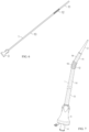
FIG. 1 is a schematic diagram of a sheath tube of a bendable ureteral access sheath for a flexible ureteroscope. In thefigure, 1 : a sheath tube; 11: a first straight tube section; 12: a bendable tube section; 13: a second straight tube section; 14: reinforcing steel wires; 15: annular reinforcing steel rings; 2: an inner tube; 3: a sheath tube hub; and 4: a zebra guidewire. -
FIG. 2 is a schematic diagram of a sheath tube of a bendable ureteral access sheath, where thesheath tube 1 having asheath tube hub 3 attached to its tail end comprises a firststraight tube section 11, abendable tube section 12, a secondstraight tube section 13, reinforcingsteel wires 14, and annular reinforcingsteel rings 15, where the first and second straight tube sections (11 and 13) are each reinforced with the reinforcingsteel wires 14 in their walls, and thebendable tube section 12 is reinforced with the annular reinforcingsteel rings 15 in its wall. -
FIG. 3 is a schematic diagram of a bendable ureteral access sheath, comprising:- (i) a
sheath tube 1 having asheath tube hub 3 attached to its tail end, comprising a firststraight tube section 11, abendable tube section 12, a secondstraight tube section 13, reinforcingsteel wires 14, and annular reinforcingsteel rings 15, where the first and second straight tube sections (11 and 13) are each reinforced with the reinforcingsteel wires 14 in their walls, and thebendable tube section 12 is reinforced with the annular reinforcingsteel rings 15 in its wall; and - (ii) an
inner tube 2, which can functions as a dilator or obturator, having a tapered tip on its front end and an inner tube knob 4 attached to its tail end; where theinner tube 2 is fully engaged with thesheath tube 1 via thesheath tube hub 3 and the inner tube knob 4.
- (i) a
-
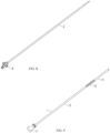
FIG. 4 is a schematic diagram of the bendable ureteral access sheath ofFIG. 3 , comprising: (i) asheath tube 1 having asheath tube hub 3 attached to its tail end, comprising a firststraight tube section 11, abendable tube section 12, and a secondstraight tube section 13; and (ii) aninner tube 2 having a tapered tip on its front end and an inner tube knob 4 attached to its tail end; where theinner tube 2 is fully engaged with thesheath tube 1 via thesheath tube hub 3 and the inner tube knob 4. -
FIG. 5 is a schematic diagram of aninner tube 2 of the bendable ureteral access sheath ofFIG. 3 , having a tapered tip on its front end and an inner tube knob 4 attached to its tail end. -
FIG. 6 is a schematic diagram of asheath tube 1 of the bendable ureteral access sheath ofFIG. 3 , comprising a firststraight tube section 11, abendable tube section 12, a secondstraight tube section 13, and asheath tube hub 3, where thesheath tube hub 3 is attached to the tail end of thesheath tube 1. -
FIG. 7 is a schematic diagram of a bendable ureteral access sheath, comprising: (i) asheath tube 1 having asheath tube hub 3 attached to its tail end, comprising a firststraight tube section 11, abendable tube section 12, a secondstraight tube section 13, reinforcingsteel wires 14, and annular reinforcingsteel rings 15, where the first and second straight tube sections (11 and 13) are each reinforced with the reinforcingsteel wires 14 in their walls and thebendable tube section 12 is reinforced with the annular reinforcingsteel rings 15 in its wall; and (ii) aninner tube 2 having a tapered tip on its front end and an inner tube knob 4 attached to its tail end; where theinner tube 2 is fully engaged with thesheath tube 1 via thesheath tube hub 3 and the inner tube knob 4. -
FIG. 8 is a schematic diagram of aninner tube 2 of the bendable ureteral access sheath ofFIG. 7 , having a tapered tip on its front end and an inner tube knob 4 attached to its tail end. -
FIG. 9 is a schematic diagram of asheath tube 1 of the bendable ureteral access sheath ofFIG. 7 , comprising a firststraight tube section 11, abendable tube section 12, a secondstraight tube section 13, and asheath tube hub 3, where thesheath tube hub 3 is attached to the tail end of thesheath tube 1. - The disclosure will be further understood by the following non-limiting examples.
- According to a bendable ureteral access sheath of the example as shown in
FIG. 1 , the bendable ureteral access sheath comprises asheath tube 1, aninner tube 2, and asheath tube hub 3. Thesheath tube 1 is sleeved on the outside of theinner tube 2. Thesheath tube hub 3 is connected to the tail end of thesheath tube 1. Theinner tube 2 has a lumen for a zebra guidewire 4 to pass through. The front end of theinner tube 2 is longer than thesheath tube 1 and is extended out beyond the front end of thesheath tube 1. - The
sheath tube 1 comprises a firststraight tube section 11, abendable tube section 12, and a secondstraight tube section 13 connected sequentially, wherein the secondstraight tube section 13 is longer than the firststraight tube section 11. The tube walls of the firststraight tube section 11 and the secondstraight tube section 13 are reinforced with reinforcingsteel wires 14 longitudinally at equal intervals. The reinforcingsteel wires 14 can enhance the strength of thesheath tube 1 to provide good support for the ureteral lumen and allow imaging and positioning by intraoperative X-rays during surgery to increase the efficiency of operation. - The
bendable tube section 12 has a flexible and foldable corrugated tube structure, whereinannular reinforcing rings 15 are placed in the flexible and foldable corrugated tube structure. Theannular reinforcing rings 15 can ensure a liquid passageway of thebendable tube section 12 clear by preventing thebendable tube section 12 from being squeezed and blocked by the ureteral lumen to affect the drainage as shown inFIG. 1 . - The length of the first
straight tube section 11 is preferably 3 cm and the length of thebendable tube section 12 is preferably 2 cm. The bendable ureteral access sheath having thebendable tube section 12 and the firststraight tube section 11 with such lengths is more suitable for placement and drainage at a ureteropelvic junction. - The working principle of the present disclosure is as follows.
- A zebra guidewire 4 is placed in the ureter under the direct observation via a rigid ureteroscope. A bendable ureteral access sheath is pushed into the ureter along the zebra guidewire 4. During the pushing process, the first
straight tube section 11, thebendable tube section 12, and the secondstraight tube section 13 are all supported and moved forwards by theinner tube 2 of the bendable ureteral access sheath. - When encountering a physiological or pathological curvature, the first
straight tube section 11 moves up along the pre-retained zebra guidewire 4, and thebendable tube section 12 can appropriately bend and change direction to continue moving up along with the firststraight tube section 11 without directly scratching and puncturing a ureteral mucous layer, a ureteral muscle layer, or a ureteral wall during placement, thereby effectively protecting the ureteral structure. -
FIGS. 3 ,4 , and7 each show a bendable ureteral access sheath with aninner tube 2 fully engaged with asheath tube 1, where the tapered tip of theinner tube 2 extended out of the front end of thesheath tube 1 to ease the insertion of the bendable ureteral access into a ureter. Once the bendable ureteral access sheath is in a desired location, theinner tube 2 is removed to provide a working channel for a flexible ureteroscope. - The
sheath tube 1 has a front end and a tail end. The distance between the front and tail ends defines the length of thesheath tube 1. In certain embodiments, thesheath tube 1 has a length ranging from about 20 to about 60 cm, from about 20 to about 55 cm, from about 30 to about 50 cm, or from about 30 to about 45 cm. In certain embodiments, thesheath tube 1 has a length ranging from about 20 to about 60 cm. In certain embodiments, thesheath tube 1 has a length ranging from about 20 to about 55 cm. In certain embodiments, thesheath tube 1 has a length ranging from about 30 to about 50 cm. In certain embodiments, thesheath tube 1 has a length ranging from about 30 to about 45 cm. In certain embodiments, thesheath tube 1 has a length of about 35, about 37, about 40, about 42, or about 45 cm. - In certain embodiments, the
sheath tube 1 is made from a plastic material. In certain embodiments, thesheath tube 1 is made from a fluorinated ethylene propylene (FEP) copolymer, latex, a nylon, a polyether block amide, a polyethylene, a polyethylene terephthalate (PET), a polytetrafluoroethylene (PTFE), a polyurethane, or a silicone. - In certain embodiments, the first
straight tube section 11 has a length ranging from about 15 to about 55 cm, from about 25 to about 55 cm, from about 30 to about 45 cm, from about 30 to about 42 cm, or from about 30 to about 40 cm. In certain embodiments, the firststraight tube section 11 has a length ranging from about 15 to about 55 cm. In certain embodiments, the firststraight tube section 11 has a length ranging from about 25 to about 55 cm. In certain embodiments, the firststraight tube section 11 has a length ranging from about 30 to about 45 cm. In certain embodiments, the firststraight tube section 11 has a length ranging from about 30 to about 42 cm. In certain embodiments, the firststraight tube section 11 has a length ranging from about 30 to about 40 cm. In certain embodiments, the firststraight tube section 11 has a length of about 30, about 32, about 35, about 37, about 40, about 42, or about 45 cm. - In certain embodiments, the first
straight tube section 11 has an inner diameter (I.D.) ranging from about 8 to about 20 French, from about 10 to about 15 French, or from about 11 to about 14 French. In certain embodiments, the firststraight tube section 11 has an I.D. ranging from about 8 to about 20 French. In certain embodiments, the firststraight tube section 11 has an I.D. ranging from about 10 to about 15 French. In certain embodiments, the firststraight tube section 11 has an I.D. ranging from about 11 to about 14 French. In certain embodiments, the firststraight tube section 11 has an I.D. of about 11, about 12, about 13, or about 14 French. - In certain embodiments, the first
straight tube section 11 has an outer diameter (O.D.) ranging from about 9 to about 22 French, from about 11 to about 17 French, or from about 12 to about 16 French. In certain embodiments, the firststraight tube section 11 has an O.D. ranging from about 9 to about 22 French. In certain embodiments, the firststraight tube section 11 has an O.D. ranging from about 11 to about 17 French. In certain embodiments, the firststraight tube section 11 has an O.D. ranging from about 12 to about 16 French. In certain embodiments, the firststraight tube section 11 has an O.D. of about 12, about 13, about 14, about 15, or about 16 French. - In certain embodiments, the
bendable tube section 12 has a length that is no greater than that of the secondstraight tube section 13. In certain embodiments, thebendable tube section 12 has a length that is less than that of the secondstraight tube section 13. - In certain embodiments, the
bendable tube section 12 has a length ranging from about 1 to about 5 cm, from about 1 to about 4 cm, from about 1 to about 3 cm, or from about 1 to about 2 cm. In certain embodiments, thebendable tube section 12 has a length ranging from about 1 to about 5 cm. In certain embodiments, thebendable tube section 12 has a length ranging from about 1 to about 4 cm. In certain embodiments, thebendable tube section 12 has a length ranging from about 1 to about 3 cm. In certain embodiments, thebendable tube section 12 has a length ranging from about 1 to about 2 cm. In certain embodiments, thebendable tube section 12 has a length of about 1 or about 2 cm. - In certain embodiments, the
bendable tube section 12 has an I.D. that is the same as that of the firststraight tube section 11 or the secondstraight tube section 13. - In certain embodiments, the
bendable tube section 12 has an I.D. ranging from about 8 to about 20 French, from about 10 to about 15 French, or from about 11 to about 14 French. In certain embodiments, thebendable tube section 12 has an I.D. ranging from about 8 to about 20 French. In certain embodiments, thebendable tube section 12 has an I.D. ranging from about 10 to about 15 French. In certain embodiments, thebendable tube section 12 has an I.D. ranging from about 11 to about 14 French. In certain embodiments, thebendable tube section 12 has an I.D. of about 11, about 12, about 13, or about 14 French. - In certain embodiments, the
bendable tube section 12 has an O.D. that is no more than about 2 French larger than that of the firststraight tube section 11 or the secondstraight tube section 13. In certain embodiments, thebendable tube section 12 has an O.D. that is no more than about 1 French larger than that of the firststraight tube section 11 or the secondstraight tube section 13. In certain embodiments, thebendable tube section 12 has an O.D. that is the same as that of the firststraight tube section 11 or the secondstraight tube section 13. - In certain embodiments, the
bendable tube section 12 has an outer diameter (O.D.) ranging from about 9 to about 23 French, from about 11 to about 18 French, or from about 12 to about 17 French. In certain embodiments, thebendable tube section 12 has an O.D. ranging from about 9 to about 23 French. In certain embodiments, thebendable tube section 12 has an O.D. ranging from about 11 to about 18 French. In certain embodiments, thebendable tube section 12 has an O.D. ranging from about 12 to about 17 French. In certain embodiments, thebendable tube section 12 has an O.D. of about 12, about 13, about 14, about 15, about 16, or about 17 French. - In certain embodiments, the second
straight tube section 13 has a length that is no greater than that of the firststraight tube section 11. In certain embodiments, the secondstraight tube section 13 has a length that is less than that of the secondstraight tube section 13. - In certain embodiments, the second
straight tube section 13 has a length ranging from about 1 to about 5 cm, from about 2 to about 4 cm, or from about 2 to about 3 cm. In certain embodiments, the secondstraight tube section 13 has a length ranging from about 1 to about 5 cm. In certain embodiments, the secondstraight tube section 13 has a length ranging from about 2 to about 4 cm. In certain embodiments, the secondstraight tube section 13 has a length ranging from about 2 to about 3 cm. In certain embodiments, the secondstraight tube section 13 has a length of about 2 or about 3 cm. - In certain embodiments, the second
straight tube section 13 has an I.D. that is the same as that of the firststraight tube section 11 or thebendable tube section 12. - In certain embodiments, the second
straight tube section 13 has an I.D. ranging from about 8 to about 20 French, from about 10 to about 15 French, or from about 11 to about 14 French. In certain embodiments, the secondstraight tube section 13 has an I.D. ranging from about 8 to about 20 French. In certain embodiments, the secondstraight tube section 13 has an I.D. ranging from about 10 to about 15 French. In certain embodiments, the secondstraight tube section 13 has an I.D. ranging from about 11 to about 14 French. In certain embodiments, the secondstraight tube section 13 has an I.D. of about 11, about 12, about 13, or about 14 French. - In certain embodiments, the second
straight tube section 13 has an O.D. that is no greater than that of the firststraight tube section 11. In certain embodiments, the secondstraight tube section 13 has an O.D. that is the same as that of the firststraight tube section 11. - In certain embodiments, the second
straight tube section 13 has an O.D. ranging from about 9 to about 22 French, from about 11 to about 17 French, or from about 12 to about 16 French. In certain embodiments, the secondstraight tube section 13 has an O.D. ranging from about 9 to about 22 French. In certain embodiments, the secondstraight tube section 13 has an O.D. ranging from about 11 to about 17 French. In certain embodiments, the secondstraight tube section 13 has an O.D. ranging from about 12 to about 16 French. In certain embodiments, the secondstraight tube section 13 has an O.D. of about 12, about 13, about 14, about 15, or about 16 French. - The
inner tube 2 has a front end and a tail end. The distance between the front and tail ends defines the length of theinner tube 2. In certain embodiments, theinner tube 2 has a length that is greater than that of thesheath tube 1. In certain embodiments, theinner tube 2 has a length that is about 1, about 2, about 3, about 4, or about 5 cm greater than that of thesheath tube 1. - In certain embodiments, the
inner tube 2 has a length ranging from about 20 to about 65 cm, from about 20 to about 60 cm, from about 30 to about 55 cm, or from about 30 to about 50 cm. In certain embodiments, theinner tube 2 has a length ranging from about 20 to about 65 cm. In certain embodiments, theinner tube 2 has a length ranging from about 20 to about 60 cm. In certain embodiments, theinner tube 2 has a length ranging from about 30 to about 55 cm. In certain embodiments, theinner tube 2 has a length ranging from about 30 to about 50 cm. In certain embodiments, theinner tube 2 has a length of about 37, about 40, about 42, about 45, about 47, or about 50 cm. - In certain embodiments, the
inner tube 2 has an I.D. that is sufficient to allow a guidewire passing through. - In certain embodiments, the
inner tube 2 has an O.D. that is no greater than that of the firststraight tube section 11, thebendable tube section 12, or the secondstraight tube section 13. In certain embodiments, theinner tube 2 has an O.D. ranging from about 8 to about 20 French, from about 10 to about 15 French, or from about 11 to about 14 French. In certain embodiments, theinner tube 2 has an O.D. ranging from about 8 to about 20 French. In certain embodiments, theinner tube 2 has an O.D. ranging from about 10 to about 15 French. In certain embodiments, theinner tube 2 has an O.D. ranging from about 11 to about 14 French. In certain embodiments, theinner tube 2 has an O.D. of about 11, about 12, about 13, or about 14 French. - In certain embodiments, the
inner tube 2 is made from a plastic material. In certain embodiments, theinner tube 2 is made from a fluorinated ethylene propylene (FEP) copolymer, latex, a nylon, a polyether block amide, a polyethylene, a polyethylene terephthalate (PET), a polytetrafluoroethylene (PTFE), a polyurethane, or a silicone. - In one embodiment, provided herein is a method, not forming part of the present invention, of providing a working channel for an operation, comprising the steps of:
- a. inserting a bendable ureteral access sheath provided herein into a urethra to an operating position; and
- b. retracting the
inner tube 2 from the urethra such that thesheath tube 1 remains in the urethra as a working channel. - In another embodiment, provided herein is a method, not forming part of the present invention, of providing a working channel for an operation, comprising the steps of:
- a. inserting a bendable ureteral access sheath provided herein into a urethra along a guidewire to an operating position; and
- b. retracting the
inner tube 2 from the urethra such that thesheath tube 1 remains in the urethra as a working channel. - The examples set forth above are provided to give those of ordinary skill in the art with a complete disclosure and description of how to make and use the claimed embodiments and are not intended to limit the scope of what is disclosed herein. Modifications that are obvious to persons of skill in the art are intended to be within the scope of the following claims.
Claims (5)
- A bendable ureteral access sheath comprising a sheath tube (1), an inner tube (2), and a sheath tube hub (3); hub; wherein the sheath tube is sleeved on the outside of the inner tube; wherein the sheath tube hub is connected to the tail end of the sheath tube; and wherein the sheath tube comprises a first straight tube section (11), a bendable tube section (12), and a second straight tube section (13), where the first straight tube section, bendable tube section, and second straight tube section are connected to each other sequentially, where the first and second straight tube sections each comprise reinforcing steel wires (14) in the wall of each straight tube section, where the first and second straight tube sections each are kink-resistant, and the bendable tube section is of a flexible structure and comprises annular reinforcing rings (15) in a foldable tube structure, characterized in thatsaid annular reinforcing rings are made of steel and in thatsaid foldable tube structure is corrugated.
- The bendable ureteral access sheath of claim 1, wherein the reinforcing steel wires are configured longitudinally in the tube walls of the first and second straight tube sections at equal intervals.
- The bendable ureteral access sheath of claim 1 or 2, wherein the sheath tube is made of a plastic material via injection molding, and the sheath tube has interior and outer walls each coated with a hydrophilic coating.
- The bendable ureteral access sheath of any one of claims 1 to 3, wherein the inner tube is made of a polytetrafluoroethylene having a certain bendability.
- The bendable ureteral access sheath of any one of claims 1 to 4, wherein the bendable tube section has a length ranging from 1 to 2 cm and the first straight tube section has a length ranging from 2 to 3 cm.
Applications Claiming Priority (1)
| Application Number | Priority Date | Filing Date | Title |
|---|---|---|---|
| CN201920466208.0U CN209952029U (en) | 2019-04-03 | 2019-04-03 | Direction-changeable ureter soft lens guiding sheath |
Publications (2)
| Publication Number | Publication Date |
|---|---|
| EP3721933A1 EP3721933A1 (en) | 2020-10-14 |
| EP3721933B1 true EP3721933B1 (en) | 2024-02-21 |
Family
ID=69242020
Family Applications (1)
| Application Number | Title | Priority Date | Filing Date |
|---|---|---|---|
| EP20167438.9A Active EP3721933B1 (en) | 2019-04-03 | 2020-03-31 | Bendable ureteral access sheath |
Country Status (3)
| Country | Link |
|---|---|
| US (1) | US20200315445A1 (en) |
| EP (1) | EP3721933B1 (en) |
| CN (1) | CN209952029U (en) |
Families Citing this family (10)
| Publication number | Priority date | Publication date | Assignee | Title |
|---|---|---|---|---|
| AU2009242503B2 (en) | 2008-05-01 | 2014-11-20 | Convatec Technologies Inc. | Rectal drain appliance |
| CN105407961A (en) | 2013-08-01 | 2016-03-16 | 康沃特克科技公司 | Self-closing bag connector |
| GB201721956D0 (en) | 2017-12-27 | 2018-02-07 | Convatec Ltd | Female catheter locator tip |
| GB201721955D0 (en) | 2017-12-27 | 2018-02-07 | Convatec Ltd | Catheter wetting devices |
| BR112021024882A2 (en) | 2019-06-11 | 2022-02-01 | Convatec Technologies Inc | Urine collection bags for use with catheter products, kits incorporating the same and methods for the same |
| USD942621S1 (en) | 2020-04-02 | 2022-02-01 | The First Affiliated Hospital Of Guangxi Medical University | Bendable ureteral access sheath |
| CN111658022A (en) * | 2020-07-08 | 2020-09-15 | 郑州大学第一附属医院 | Multifunctional anti-folding biopsy sheath set for human body cavity |
| CN114209270A (en) * | 2021-11-25 | 2022-03-22 | 北京大学第三医院 | Spinal interbody fusion endoscope structure |
| CN114451970B (en) * | 2021-12-24 | 2024-06-28 | 浙江医高医疗科技有限公司 | An improved ureteral sheath |
| CN119034084B (en) * | 2024-11-04 | 2025-03-11 | 湖南省华芯医疗器械有限公司 | Vacuum suction sheath |
Family Cites Families (10)
| Publication number | Priority date | Publication date | Assignee | Title |
|---|---|---|---|---|
| US20050004515A1 (en) * | 2002-11-15 | 2005-01-06 | Hart Charles C. | Steerable kink resistant sheath |
| US7654989B2 (en) * | 2003-04-08 | 2010-02-02 | C. R. Bard, Inc. | Ureteral access sheath |
| US20050222581A1 (en) * | 2004-03-30 | 2005-10-06 | Vance Products Incorporated, D/B/A | Multiple lumen access sheath |
| EP1971272A2 (en) * | 2006-01-09 | 2008-09-24 | VANCE PRODUCTS INCORPORATED d/b/a COOK UROLOGICAL INCORPORATED | Deflectable tip access sheath |
| US9155451B2 (en) * | 2006-03-02 | 2015-10-13 | Syntheon, Llc | Variably flexible insertion device and method for variably flexing an insertion device |
| US9782566B1 (en) * | 2008-05-01 | 2017-10-10 | Annex Medical, Inc. | Bend limiting access sheath |
| WO2010132560A1 (en) * | 2009-05-14 | 2010-11-18 | Vance Products Incorporated, D/B/A/ Cook Urological Incorporated | Access sheath with active deflection |
| MX2017010622A (en) * | 2015-02-23 | 2018-04-13 | Bard Inc C R | Access sheath, access system, and related methods. |
| US10702305B2 (en) * | 2016-03-23 | 2020-07-07 | Coopersurgical, Inc. | Operative cannulas and related methods |
| EP4032578A1 (en) * | 2016-07-13 | 2022-07-27 | Perfuze Limited | High flexibility, kink resistant catheter shaft |
-
2019
- 2019-04-03 CN CN201920466208.0U patent/CN209952029U/en active Active
-
2020
- 2020-03-31 EP EP20167438.9A patent/EP3721933B1/en active Active
- 2020-04-02 US US16/839,036 patent/US20200315445A1/en not_active Abandoned
Also Published As
| Publication number | Publication date |
|---|---|
| CN209952029U (en) | 2020-01-17 |
| EP3721933A1 (en) | 2020-10-14 |
| US20200315445A1 (en) | 2020-10-08 |
Similar Documents
| Publication | Publication Date | Title |
|---|---|---|
| EP3721933A1 (en) | Bendable ureteral access sheath | |
| US20210196924A1 (en) | Medical tube clearance | |
| US8747388B2 (en) | Access and drainage devices | |
| US10201689B1 (en) | Urethral balloon dilator catheter | |
| US8343036B1 (en) | Flaccid tubular membrane and insertion appliance for surgical intubation | |
| EP3535015B1 (en) | Drainage catheter | |
| AU2010313314B2 (en) | Flexible endoscope with modifiable stiffness | |
| CN102834042B (en) | Endoscope cap with ramp | |
| US6599237B1 (en) | Instrument and method for facilitating endoscopic examination and surgical procedures | |
| CN108495594B (en) | retrieval system | |
| US20190350603A1 (en) | Device for removing kidney stones | |
| US20090018525A1 (en) | Tapered catheter devices | |
| US20080262308A1 (en) | Method and system for performing continuous flow endoscopy | |
| US20060173525A1 (en) | Methods and systems for deploying luminal prostheses | |
| WO2008022262A1 (en) | Guidewire structure including a medical guidewire | |
| CN211066512U (en) | Flexible ureteroscope delivery sheath assembly | |
| US20160089172A1 (en) | Devices and methods for applying suction | |
| CN110215262A (en) | A kind of flexible attraction sheath | |
| WO2017158069A1 (en) | A catheter assembly | |
| CN210903223U (en) | Bendable suction sheath | |
| US20080171991A1 (en) | Sheath tube catheter | |
| US11344188B1 (en) | Actively bendable sheath for delivering medical instrument therethrough and method thereof | |
| CN219921794U (en) | A safe anti-blocking drainage tube for neurosurgery | |
| EP4385552A1 (en) | An introducer assembly having a low-profile access sheath and a hub assembly | |
| CN219681429U (en) | Ureter guiding sheath tube |
Legal Events
| Date | Code | Title | Description |
|---|---|---|---|
| PUAI | Public reference made under article 153(3) epc to a published international application that has entered the european phase |
Free format text: ORIGINAL CODE: 0009012 |
|
| STAA | Information on the status of an ep patent application or granted ep patent |
Free format text: STATUS: REQUEST FOR EXAMINATION WAS MADE |
|
| 17P | Request for examination filed |
Effective date: 20200331 |
|
| AK | Designated contracting states |
Kind code of ref document: A1 Designated state(s): AL AT BE BG CH CY CZ DE DK EE ES FI FR GB GR HR HU IE IS IT LI LT LU LV MC MK MT NL NO PL PT RO RS SE SI SK SM TR |
|
| AX | Request for extension of the european patent |
Extension state: BA ME |
|
| RIC1 | Information provided on ipc code assigned before grant |
Ipc: A61B 1/00 20060101ALI20230915BHEP Ipc: A61B 1/005 20060101ALI20230915BHEP Ipc: A61M 25/00 20060101ALI20230915BHEP Ipc: A61M 25/06 20060101AFI20230915BHEP |
|
| GRAP | Despatch of communication of intention to grant a patent |
Free format text: ORIGINAL CODE: EPIDOSNIGR1 |
|
| STAA | Information on the status of an ep patent application or granted ep patent |
Free format text: STATUS: GRANT OF PATENT IS INTENDED |
|
| INTG | Intention to grant announced |
Effective date: 20231109 |
|
| GRAS | Grant fee paid |
Free format text: ORIGINAL CODE: EPIDOSNIGR3 |
|
| GRAA | (expected) grant |
Free format text: ORIGINAL CODE: 0009210 |
|
| STAA | Information on the status of an ep patent application or granted ep patent |
Free format text: STATUS: THE PATENT HAS BEEN GRANTED |
|
| AK | Designated contracting states |
Kind code of ref document: B1 Designated state(s): AL AT BE BG CH CY CZ DE DK EE ES FI FR GB GR HR HU IE IS IT LI LT LU LV MC MK MT NL NO PL PT RO RS SE SI SK SM TR |
|
| REG | Reference to a national code |
Ref country code: GB Ref legal event code: FG4D |
|
| REG | Reference to a national code |
Ref country code: CH Ref legal event code: EP |
|
| REG | Reference to a national code |
Ref country code: IE Ref legal event code: FG4D |
|
| REG | Reference to a national code |
Ref country code: DE Ref legal event code: R096 Ref document number: 602020025905 Country of ref document: DE |
|
| RAP4 | Party data changed (patent owner data changed or rights of a patent transferred) |
Owner name: GUANGXI MEDICAL ASSOCIATION |
|
| REG | Reference to a national code |
Ref country code: SE Ref legal event code: TRGR |
|
| REG | Reference to a national code |
Ref country code: GB Ref legal event code: S117 Free format text: REQUEST FILED; REQUEST FOR CORRECTION UNDER SECTION 117 FILED ON 11 APRIL 2024 |
|
| REG | Reference to a national code |
Ref country code: GB Ref legal event code: S117 Free format text: CORRECTIONS ALLOWED; REQUEST FOR CORRECTION UNDER SECTION 117 FILED ON 11 APRIL 2024 WAS ALLOWED ON 30 APRIL 2024 |
|
| REG | Reference to a national code |
Ref country code: LT Ref legal event code: MG9D |
|
| REG | Reference to a national code |
Ref country code: NL Ref legal event code: MP Effective date: 20240221 |
|
| PG25 | Lapsed in a contracting state [announced via postgrant information from national office to epo] |
Ref country code: IS Free format text: LAPSE BECAUSE OF FAILURE TO SUBMIT A TRANSLATION OF THE DESCRIPTION OR TO PAY THE FEE WITHIN THE PRESCRIBED TIME-LIMIT Effective date: 20240621 |
|
| PG25 | Lapsed in a contracting state [announced via postgrant information from national office to epo] |
Ref country code: LT Free format text: LAPSE BECAUSE OF FAILURE TO SUBMIT A TRANSLATION OF THE DESCRIPTION OR TO PAY THE FEE WITHIN THE PRESCRIBED TIME-LIMIT Effective date: 20240221 |
|
| PG25 | Lapsed in a contracting state [announced via postgrant information from national office to epo] |
Ref country code: GR Free format text: LAPSE BECAUSE OF FAILURE TO SUBMIT A TRANSLATION OF THE DESCRIPTION OR TO PAY THE FEE WITHIN THE PRESCRIBED TIME-LIMIT Effective date: 20240522 |
|
| REG | Reference to a national code |
Ref country code: AT Ref legal event code: MK05 Ref document number: 1658568 Country of ref document: AT Kind code of ref document: T Effective date: 20240221 |
|
| PG25 | Lapsed in a contracting state [announced via postgrant information from national office to epo] |
Ref country code: RS Free format text: LAPSE BECAUSE OF FAILURE TO SUBMIT A TRANSLATION OF THE DESCRIPTION OR TO PAY THE FEE WITHIN THE PRESCRIBED TIME-LIMIT Effective date: 20240521 Ref country code: HR Free format text: LAPSE BECAUSE OF FAILURE TO SUBMIT A TRANSLATION OF THE DESCRIPTION OR TO PAY THE FEE WITHIN THE PRESCRIBED TIME-LIMIT Effective date: 20240221 Ref country code: NL Free format text: LAPSE BECAUSE OF FAILURE TO SUBMIT A TRANSLATION OF THE DESCRIPTION OR TO PAY THE FEE WITHIN THE PRESCRIBED TIME-LIMIT Effective date: 20240221 |
|
| PG25 | Lapsed in a contracting state [announced via postgrant information from national office to epo] |
Ref country code: ES Free format text: LAPSE BECAUSE OF FAILURE TO SUBMIT A TRANSLATION OF THE DESCRIPTION OR TO PAY THE FEE WITHIN THE PRESCRIBED TIME-LIMIT Effective date: 20240221 |
|
| PG25 | Lapsed in a contracting state [announced via postgrant information from national office to epo] |
Ref country code: AT Free format text: LAPSE BECAUSE OF FAILURE TO SUBMIT A TRANSLATION OF THE DESCRIPTION OR TO PAY THE FEE WITHIN THE PRESCRIBED TIME-LIMIT Effective date: 20240221 |
|
| PG25 | Lapsed in a contracting state [announced via postgrant information from national office to epo] |
Ref country code: RS Free format text: LAPSE BECAUSE OF FAILURE TO SUBMIT A TRANSLATION OF THE DESCRIPTION OR TO PAY THE FEE WITHIN THE PRESCRIBED TIME-LIMIT Effective date: 20240521 Ref country code: NO Free format text: LAPSE BECAUSE OF FAILURE TO SUBMIT A TRANSLATION OF THE DESCRIPTION OR TO PAY THE FEE WITHIN THE PRESCRIBED TIME-LIMIT Effective date: 20240521 Ref country code: NL Free format text: LAPSE BECAUSE OF FAILURE TO SUBMIT A TRANSLATION OF THE DESCRIPTION OR TO PAY THE FEE WITHIN THE PRESCRIBED TIME-LIMIT Effective date: 20240221 Ref country code: LT Free format text: LAPSE BECAUSE OF FAILURE TO SUBMIT A TRANSLATION OF THE DESCRIPTION OR TO PAY THE FEE WITHIN THE PRESCRIBED TIME-LIMIT Effective date: 20240221 Ref country code: IS Free format text: LAPSE BECAUSE OF FAILURE TO SUBMIT A TRANSLATION OF THE DESCRIPTION OR TO PAY THE FEE WITHIN THE PRESCRIBED TIME-LIMIT Effective date: 20240621 Ref country code: HR Free format text: LAPSE BECAUSE OF FAILURE TO SUBMIT A TRANSLATION OF THE DESCRIPTION OR TO PAY THE FEE WITHIN THE PRESCRIBED TIME-LIMIT Effective date: 20240221 Ref country code: GR Free format text: LAPSE BECAUSE OF FAILURE TO SUBMIT A TRANSLATION OF THE DESCRIPTION OR TO PAY THE FEE WITHIN THE PRESCRIBED TIME-LIMIT Effective date: 20240522 Ref country code: FI Free format text: LAPSE BECAUSE OF FAILURE TO SUBMIT A TRANSLATION OF THE DESCRIPTION OR TO PAY THE FEE WITHIN THE PRESCRIBED TIME-LIMIT Effective date: 20240221 Ref country code: ES Free format text: LAPSE BECAUSE OF FAILURE TO SUBMIT A TRANSLATION OF THE DESCRIPTION OR TO PAY THE FEE WITHIN THE PRESCRIBED TIME-LIMIT Effective date: 20240221 Ref country code: BG Free format text: LAPSE BECAUSE OF FAILURE TO SUBMIT A TRANSLATION OF THE DESCRIPTION OR TO PAY THE FEE WITHIN THE PRESCRIBED TIME-LIMIT Effective date: 20240221 Ref country code: AT Free format text: LAPSE BECAUSE OF FAILURE TO SUBMIT A TRANSLATION OF THE DESCRIPTION OR TO PAY THE FEE WITHIN THE PRESCRIBED TIME-LIMIT Effective date: 20240221 |
|
| PG25 | Lapsed in a contracting state [announced via postgrant information from national office to epo] |
Ref country code: PL Free format text: LAPSE BECAUSE OF FAILURE TO SUBMIT A TRANSLATION OF THE DESCRIPTION OR TO PAY THE FEE WITHIN THE PRESCRIBED TIME-LIMIT Effective date: 20240221 Ref country code: PT Free format text: LAPSE BECAUSE OF FAILURE TO SUBMIT A TRANSLATION OF THE DESCRIPTION OR TO PAY THE FEE WITHIN THE PRESCRIBED TIME-LIMIT Effective date: 20240621 |
|
| PG25 | Lapsed in a contracting state [announced via postgrant information from national office to epo] |
Ref country code: PT Free format text: LAPSE BECAUSE OF FAILURE TO SUBMIT A TRANSLATION OF THE DESCRIPTION OR TO PAY THE FEE WITHIN THE PRESCRIBED TIME-LIMIT Effective date: 20240621 Ref country code: PL Free format text: LAPSE BECAUSE OF FAILURE TO SUBMIT A TRANSLATION OF THE DESCRIPTION OR TO PAY THE FEE WITHIN THE PRESCRIBED TIME-LIMIT Effective date: 20240221 Ref country code: LV Free format text: LAPSE BECAUSE OF FAILURE TO SUBMIT A TRANSLATION OF THE DESCRIPTION OR TO PAY THE FEE WITHIN THE PRESCRIBED TIME-LIMIT Effective date: 20240221 |
|
| PG25 | Lapsed in a contracting state [announced via postgrant information from national office to epo] |
Ref country code: DK Free format text: LAPSE BECAUSE OF FAILURE TO SUBMIT A TRANSLATION OF THE DESCRIPTION OR TO PAY THE FEE WITHIN THE PRESCRIBED TIME-LIMIT Effective date: 20240221 |
|
| PG25 | Lapsed in a contracting state [announced via postgrant information from national office to epo] |
Ref country code: SM Free format text: LAPSE BECAUSE OF FAILURE TO SUBMIT A TRANSLATION OF THE DESCRIPTION OR TO PAY THE FEE WITHIN THE PRESCRIBED TIME-LIMIT Effective date: 20240221 |
|
| PG25 | Lapsed in a contracting state [announced via postgrant information from national office to epo] |
Ref country code: CZ Free format text: LAPSE BECAUSE OF FAILURE TO SUBMIT A TRANSLATION OF THE DESCRIPTION OR TO PAY THE FEE WITHIN THE PRESCRIBED TIME-LIMIT Effective date: 20240221 Ref country code: EE Free format text: LAPSE BECAUSE OF FAILURE TO SUBMIT A TRANSLATION OF THE DESCRIPTION OR TO PAY THE FEE WITHIN THE PRESCRIBED TIME-LIMIT Effective date: 20240221 |
|
| PG25 | Lapsed in a contracting state [announced via postgrant information from national office to epo] |
Ref country code: SK Free format text: LAPSE BECAUSE OF FAILURE TO SUBMIT A TRANSLATION OF THE DESCRIPTION OR TO PAY THE FEE WITHIN THE PRESCRIBED TIME-LIMIT Effective date: 20240221 |
|
| PG25 | Lapsed in a contracting state [announced via postgrant information from national office to epo] |
Ref country code: SM Free format text: LAPSE BECAUSE OF FAILURE TO SUBMIT A TRANSLATION OF THE DESCRIPTION OR TO PAY THE FEE WITHIN THE PRESCRIBED TIME-LIMIT Effective date: 20240221 Ref country code: SK Free format text: LAPSE BECAUSE OF FAILURE TO SUBMIT A TRANSLATION OF THE DESCRIPTION OR TO PAY THE FEE WITHIN THE PRESCRIBED TIME-LIMIT Effective date: 20240221 Ref country code: RO Free format text: LAPSE BECAUSE OF FAILURE TO SUBMIT A TRANSLATION OF THE DESCRIPTION OR TO PAY THE FEE WITHIN THE PRESCRIBED TIME-LIMIT Effective date: 20240221 Ref country code: EE Free format text: LAPSE BECAUSE OF FAILURE TO SUBMIT A TRANSLATION OF THE DESCRIPTION OR TO PAY THE FEE WITHIN THE PRESCRIBED TIME-LIMIT Effective date: 20240221 Ref country code: DK Free format text: LAPSE BECAUSE OF FAILURE TO SUBMIT A TRANSLATION OF THE DESCRIPTION OR TO PAY THE FEE WITHIN THE PRESCRIBED TIME-LIMIT Effective date: 20240221 Ref country code: CZ Free format text: LAPSE BECAUSE OF FAILURE TO SUBMIT A TRANSLATION OF THE DESCRIPTION OR TO PAY THE FEE WITHIN THE PRESCRIBED TIME-LIMIT Effective date: 20240221 |
|
| PG25 | Lapsed in a contracting state [announced via postgrant information from national office to epo] |
Ref country code: LU Free format text: LAPSE BECAUSE OF NON-PAYMENT OF DUE FEES Effective date: 20240331 |
|
| PG25 | Lapsed in a contracting state [announced via postgrant information from national office to epo] |
Ref country code: MC Free format text: LAPSE BECAUSE OF FAILURE TO SUBMIT A TRANSLATION OF THE DESCRIPTION OR TO PAY THE FEE WITHIN THE PRESCRIBED TIME-LIMIT Effective date: 20240221 |
|
| REG | Reference to a national code |
Ref country code: DE Ref legal event code: R097 Ref document number: 602020025905 Country of ref document: DE |
|
| PG25 | Lapsed in a contracting state [announced via postgrant information from national office to epo] |
Ref country code: MC Free format text: LAPSE BECAUSE OF FAILURE TO SUBMIT A TRANSLATION OF THE DESCRIPTION OR TO PAY THE FEE WITHIN THE PRESCRIBED TIME-LIMIT Effective date: 20240221 Ref country code: LU Free format text: LAPSE BECAUSE OF NON-PAYMENT OF DUE FEES Effective date: 20240331 |
|
| PG25 | Lapsed in a contracting state [announced via postgrant information from national office to epo] |
Ref country code: IT Free format text: LAPSE BECAUSE OF FAILURE TO SUBMIT A TRANSLATION OF THE DESCRIPTION OR TO PAY THE FEE WITHIN THE PRESCRIBED TIME-LIMIT Effective date: 20240221 |
|
| REG | Reference to a national code |
Ref country code: BE Ref legal event code: MM Effective date: 20240331 |
|
| PLBE | No opposition filed within time limit |
Free format text: ORIGINAL CODE: 0009261 |
|
| STAA | Information on the status of an ep patent application or granted ep patent |
Free format text: STATUS: NO OPPOSITION FILED WITHIN TIME LIMIT |
|
| PG25 | Lapsed in a contracting state [announced via postgrant information from national office to epo] |
Ref country code: IT Free format text: LAPSE BECAUSE OF FAILURE TO SUBMIT A TRANSLATION OF THE DESCRIPTION OR TO PAY THE FEE WITHIN THE PRESCRIBED TIME-LIMIT Effective date: 20240221 |
|
| PG25 | Lapsed in a contracting state [announced via postgrant information from national office to epo] |
Ref country code: BE Free format text: LAPSE BECAUSE OF NON-PAYMENT OF DUE FEES Effective date: 20240331 |
|
| 26N | No opposition filed |
Effective date: 20241122 |
|
| PG25 | Lapsed in a contracting state [announced via postgrant information from national office to epo] |
Ref country code: BE Free format text: LAPSE BECAUSE OF NON-PAYMENT OF DUE FEES Effective date: 20240331 |
|
| PG25 | Lapsed in a contracting state [announced via postgrant information from national office to epo] |
Ref country code: SI Free format text: LAPSE BECAUSE OF FAILURE TO SUBMIT A TRANSLATION OF THE DESCRIPTION OR TO PAY THE FEE WITHIN THE PRESCRIBED TIME-LIMIT Effective date: 20240221 |
|
| PGFP | Annual fee paid to national office [announced via postgrant information from national office to epo] |
Ref country code: CH Payment date: 20250401 Year of fee payment: 6 |
|
| PG25 | Lapsed in a contracting state [announced via postgrant information from national office to epo] |
Ref country code: CY Free format text: LAPSE BECAUSE OF FAILURE TO SUBMIT A TRANSLATION OF THE DESCRIPTION OR TO PAY THE FEE WITHIN THE PRESCRIBED TIME-LIMIT; INVALID AB INITIO Effective date: 20200331 |
|
| PG25 | Lapsed in a contracting state [announced via postgrant information from national office to epo] |
Ref country code: HU Free format text: LAPSE BECAUSE OF FAILURE TO SUBMIT A TRANSLATION OF THE DESCRIPTION OR TO PAY THE FEE WITHIN THE PRESCRIBED TIME-LIMIT; INVALID AB INITIO Effective date: 20200331 |
|
| PG25 | Lapsed in a contracting state [announced via postgrant information from national office to epo] |
Ref country code: TR Free format text: LAPSE BECAUSE OF FAILURE TO SUBMIT A TRANSLATION OF THE DESCRIPTION OR TO PAY THE FEE WITHIN THE PRESCRIBED TIME-LIMIT Effective date: 20240221 |
|
| REG | Reference to a national code |
Ref country code: CH Ref legal event code: U11 Free format text: ST27 STATUS EVENT CODE: U-0-0-U10-U11 (AS PROVIDED BY THE NATIONAL OFFICE) Effective date: 20260401 |
|
| PGFP | Annual fee paid to national office [announced via postgrant information from national office to epo] |
Ref country code: SE Payment date: 20260219 Year of fee payment: 7 |
|
| PGFP | Annual fee paid to national office [announced via postgrant information from national office to epo] |
Ref country code: GB Payment date: 20260217 Year of fee payment: 7 |
|
| PGFP | Annual fee paid to national office [announced via postgrant information from national office to epo] |
Ref country code: DE Payment date: 20260220 Year of fee payment: 7 Ref country code: IE Payment date: 20260217 Year of fee payment: 7 |
|
| PGFP | Annual fee paid to national office [announced via postgrant information from national office to epo] |
Ref country code: FR Payment date: 20260217 Year of fee payment: 7 |