EP3721488B1 - Prismatic-pouch hybrid battery module - Google Patents
Prismatic-pouch hybrid battery module Download PDFInfo
- Publication number
- EP3721488B1 EP3721488B1 EP18812090.1A EP18812090A EP3721488B1 EP 3721488 B1 EP3721488 B1 EP 3721488B1 EP 18812090 A EP18812090 A EP 18812090A EP 3721488 B1 EP3721488 B1 EP 3721488B1
- Authority
- EP
- European Patent Office
- Prior art keywords
- frame
- cover element
- battery module
- cell stack
- cell
- Prior art date
- Legal status (The legal status is an assumption and is not a legal conclusion. Google has not performed a legal analysis and makes no representation as to the accuracy of the status listed.)
- Active
Links
Images


Classifications
-
- H—ELECTRICITY
- H01—ELECTRIC ELEMENTS
- H01M—PROCESSES OR MEANS, e.g. BATTERIES, FOR THE DIRECT CONVERSION OF CHEMICAL ENERGY INTO ELECTRICAL ENERGY
- H01M50/00—Constructional details or processes of manufacture of the non-active parts of electrochemical cells other than fuel cells, e.g. hybrid cells
- H01M50/20—Mountings; Secondary casings or frames; Racks, modules or packs; Suspension devices; Shock absorbers; Transport or carrying devices; Holders
-
- H—ELECTRICITY
- H01—ELECTRIC ELEMENTS
- H01M—PROCESSES OR MEANS, e.g. BATTERIES, FOR THE DIRECT CONVERSION OF CHEMICAL ENERGY INTO ELECTRICAL ENERGY
- H01M10/00—Secondary cells; Manufacture thereof
- H01M10/42—Methods or arrangements for servicing or maintenance of secondary cells or secondary half-cells
- H01M10/48—Accumulators combined with arrangements for measuring, testing or indicating the condition of cells, e.g. the level or density of the electrolyte
- H01M10/482—Accumulators combined with arrangements for measuring, testing or indicating the condition of cells, e.g. the level or density of the electrolyte for several batteries or cells simultaneously or sequentially
-
- H—ELECTRICITY
- H01—ELECTRIC ELEMENTS
- H01M—PROCESSES OR MEANS, e.g. BATTERIES, FOR THE DIRECT CONVERSION OF CHEMICAL ENERGY INTO ELECTRICAL ENERGY
- H01M10/00—Secondary cells; Manufacture thereof
- H01M10/60—Heating or cooling; Temperature control
- H01M10/61—Types of temperature control
- H01M10/613—Cooling or keeping cold
-
- H—ELECTRICITY
- H01—ELECTRIC ELEMENTS
- H01M—PROCESSES OR MEANS, e.g. BATTERIES, FOR THE DIRECT CONVERSION OF CHEMICAL ENERGY INTO ELECTRICAL ENERGY
- H01M10/00—Secondary cells; Manufacture thereof
- H01M10/60—Heating or cooling; Temperature control
- H01M10/62—Heating or cooling; Temperature control specially adapted for specific applications
- H01M10/625—Vehicles
-
- H—ELECTRICITY
- H01—ELECTRIC ELEMENTS
- H01M—PROCESSES OR MEANS, e.g. BATTERIES, FOR THE DIRECT CONVERSION OF CHEMICAL ENERGY INTO ELECTRICAL ENERGY
- H01M10/00—Secondary cells; Manufacture thereof
- H01M10/60—Heating or cooling; Temperature control
- H01M10/65—Means for temperature control structurally associated with the cells
- H01M10/655—Solid structures for heat exchange or heat conduction
- H01M10/6556—Solid parts with flow channel passages or pipes for heat exchange
-
- H—ELECTRICITY
- H01—ELECTRIC ELEMENTS
- H01M—PROCESSES OR MEANS, e.g. BATTERIES, FOR THE DIRECT CONVERSION OF CHEMICAL ENERGY INTO ELECTRICAL ENERGY
- H01M50/00—Constructional details or processes of manufacture of the non-active parts of electrochemical cells other than fuel cells, e.g. hybrid cells
- H01M50/10—Primary casings; Jackets or wrappings
- H01M50/102—Primary casings; Jackets or wrappings characterised by their shape or physical structure
- H01M50/105—Pouches or flexible bags
-
- H—ELECTRICITY
- H01—ELECTRIC ELEMENTS
- H01M—PROCESSES OR MEANS, e.g. BATTERIES, FOR THE DIRECT CONVERSION OF CHEMICAL ENERGY INTO ELECTRICAL ENERGY
- H01M50/00—Constructional details or processes of manufacture of the non-active parts of electrochemical cells other than fuel cells, e.g. hybrid cells
- H01M50/10—Primary casings; Jackets or wrappings
- H01M50/116—Primary casings; Jackets or wrappings characterised by the material
- H01M50/122—Composite material consisting of a mixture of organic and inorganic materials
-
- H—ELECTRICITY
- H01—ELECTRIC ELEMENTS
- H01M—PROCESSES OR MEANS, e.g. BATTERIES, FOR THE DIRECT CONVERSION OF CHEMICAL ENERGY INTO ELECTRICAL ENERGY
- H01M50/00—Constructional details or processes of manufacture of the non-active parts of electrochemical cells other than fuel cells, e.g. hybrid cells
- H01M50/10—Primary casings; Jackets or wrappings
- H01M50/116—Primary casings; Jackets or wrappings characterised by the material
- H01M50/124—Primary casings; Jackets or wrappings characterised by the material having a layered structure
-
- H—ELECTRICITY
- H01—ELECTRIC ELEMENTS
- H01M—PROCESSES OR MEANS, e.g. BATTERIES, FOR THE DIRECT CONVERSION OF CHEMICAL ENERGY INTO ELECTRICAL ENERGY
- H01M50/00—Constructional details or processes of manufacture of the non-active parts of electrochemical cells other than fuel cells, e.g. hybrid cells
- H01M50/20—Mountings; Secondary casings or frames; Racks, modules or packs; Suspension devices; Shock absorbers; Transport or carrying devices; Holders
- H01M50/204—Racks, modules or packs for multiple batteries or multiple cells
- H01M50/207—Racks, modules or packs for multiple batteries or multiple cells characterised by their shape
- H01M50/209—Racks, modules or packs for multiple batteries or multiple cells characterised by their shape adapted for prismatic or rectangular cells
-
- H—ELECTRICITY
- H01—ELECTRIC ELEMENTS
- H01M—PROCESSES OR MEANS, e.g. BATTERIES, FOR THE DIRECT CONVERSION OF CHEMICAL ENERGY INTO ELECTRICAL ENERGY
- H01M50/00—Constructional details or processes of manufacture of the non-active parts of electrochemical cells other than fuel cells, e.g. hybrid cells
- H01M50/20—Mountings; Secondary casings or frames; Racks, modules or packs; Suspension devices; Shock absorbers; Transport or carrying devices; Holders
- H01M50/204—Racks, modules or packs for multiple batteries or multiple cells
- H01M50/207—Racks, modules or packs for multiple batteries or multiple cells characterised by their shape
- H01M50/211—Racks, modules or packs for multiple batteries or multiple cells characterised by their shape adapted for pouch cells
-
- H—ELECTRICITY
- H01—ELECTRIC ELEMENTS
- H01M—PROCESSES OR MEANS, e.g. BATTERIES, FOR THE DIRECT CONVERSION OF CHEMICAL ENERGY INTO ELECTRICAL ENERGY
- H01M50/00—Constructional details or processes of manufacture of the non-active parts of electrochemical cells other than fuel cells, e.g. hybrid cells
- H01M50/20—Mountings; Secondary casings or frames; Racks, modules or packs; Suspension devices; Shock absorbers; Transport or carrying devices; Holders
- H01M50/218—Mountings; Secondary casings or frames; Racks, modules or packs; Suspension devices; Shock absorbers; Transport or carrying devices; Holders characterised by the material
- H01M50/22—Mountings; Secondary casings or frames; Racks, modules or packs; Suspension devices; Shock absorbers; Transport or carrying devices; Holders characterised by the material of the casings or racks
-
- H—ELECTRICITY
- H01—ELECTRIC ELEMENTS
- H01M—PROCESSES OR MEANS, e.g. BATTERIES, FOR THE DIRECT CONVERSION OF CHEMICAL ENERGY INTO ELECTRICAL ENERGY
- H01M50/00—Constructional details or processes of manufacture of the non-active parts of electrochemical cells other than fuel cells, e.g. hybrid cells
- H01M50/20—Mountings; Secondary casings or frames; Racks, modules or packs; Suspension devices; Shock absorbers; Transport or carrying devices; Holders
- H01M50/271—Lids or covers for the racks or secondary casings
- H01M50/273—Lids or covers for the racks or secondary casings characterised by the material
- H01M50/276—Inorganic material
-
- H—ELECTRICITY
- H01—ELECTRIC ELEMENTS
- H01M—PROCESSES OR MEANS, e.g. BATTERIES, FOR THE DIRECT CONVERSION OF CHEMICAL ENERGY INTO ELECTRICAL ENERGY
- H01M50/00—Constructional details or processes of manufacture of the non-active parts of electrochemical cells other than fuel cells, e.g. hybrid cells
- H01M50/20—Mountings; Secondary casings or frames; Racks, modules or packs; Suspension devices; Shock absorbers; Transport or carrying devices; Holders
- H01M50/271—Lids or covers for the racks or secondary casings
- H01M50/273—Lids or covers for the racks or secondary casings characterised by the material
- H01M50/278—Organic material
-
- H—ELECTRICITY
- H01—ELECTRIC ELEMENTS
- H01M—PROCESSES OR MEANS, e.g. BATTERIES, FOR THE DIRECT CONVERSION OF CHEMICAL ENERGY INTO ELECTRICAL ENERGY
- H01M50/00—Constructional details or processes of manufacture of the non-active parts of electrochemical cells other than fuel cells, e.g. hybrid cells
- H01M50/20—Mountings; Secondary casings or frames; Racks, modules or packs; Suspension devices; Shock absorbers; Transport or carrying devices; Holders
- H01M50/271—Lids or covers for the racks or secondary casings
- H01M50/273—Lids or covers for the racks or secondary casings characterised by the material
- H01M50/28—Composite material consisting of a mixture of organic and inorganic materials
-
- H—ELECTRICITY
- H01—ELECTRIC ELEMENTS
- H01M—PROCESSES OR MEANS, e.g. BATTERIES, FOR THE DIRECT CONVERSION OF CHEMICAL ENERGY INTO ELECTRICAL ENERGY
- H01M50/00—Constructional details or processes of manufacture of the non-active parts of electrochemical cells other than fuel cells, e.g. hybrid cells
- H01M50/20—Mountings; Secondary casings or frames; Racks, modules or packs; Suspension devices; Shock absorbers; Transport or carrying devices; Holders
- H01M50/271—Lids or covers for the racks or secondary casings
- H01M50/273—Lids or covers for the racks or secondary casings characterised by the material
- H01M50/282—Lids or covers for the racks or secondary casings characterised by the material having a layered structure
-
- H—ELECTRICITY
- H01—ELECTRIC ELEMENTS
- H01M—PROCESSES OR MEANS, e.g. BATTERIES, FOR THE DIRECT CONVERSION OF CHEMICAL ENERGY INTO ELECTRICAL ENERGY
- H01M50/00—Constructional details or processes of manufacture of the non-active parts of electrochemical cells other than fuel cells, e.g. hybrid cells
- H01M50/20—Mountings; Secondary casings or frames; Racks, modules or packs; Suspension devices; Shock absorbers; Transport or carrying devices; Holders
- H01M50/296—Mountings; Secondary casings or frames; Racks, modules or packs; Suspension devices; Shock absorbers; Transport or carrying devices; Holders characterised by terminals of battery packs
-
- H—ELECTRICITY
- H01—ELECTRIC ELEMENTS
- H01M—PROCESSES OR MEANS, e.g. BATTERIES, FOR THE DIRECT CONVERSION OF CHEMICAL ENERGY INTO ELECTRICAL ENERGY
- H01M10/00—Secondary cells; Manufacture thereof
- H01M10/42—Methods or arrangements for servicing or maintenance of secondary cells or secondary half-cells
- H01M10/48—Accumulators combined with arrangements for measuring, testing or indicating the condition of cells, e.g. the level or density of the electrolyte
-
- H—ELECTRICITY
- H01—ELECTRIC ELEMENTS
- H01M—PROCESSES OR MEANS, e.g. BATTERIES, FOR THE DIRECT CONVERSION OF CHEMICAL ENERGY INTO ELECTRICAL ENERGY
- H01M10/00—Secondary cells; Manufacture thereof
- H01M10/60—Heating or cooling; Temperature control
- H01M10/64—Heating or cooling; Temperature control characterised by the shape of the cells
- H01M10/647—Prismatic or flat cells, e.g. pouch cells
-
- H—ELECTRICITY
- H01—ELECTRIC ELEMENTS
- H01M—PROCESSES OR MEANS, e.g. BATTERIES, FOR THE DIRECT CONVERSION OF CHEMICAL ENERGY INTO ELECTRICAL ENERGY
- H01M10/00—Secondary cells; Manufacture thereof
- H01M10/60—Heating or cooling; Temperature control
- H01M10/65—Means for temperature control structurally associated with the cells
- H01M10/656—Means for temperature control structurally associated with the cells characterised by the type of heat-exchange fluid
- H01M10/6567—Liquids
-
- H—ELECTRICITY
- H01—ELECTRIC ELEMENTS
- H01M—PROCESSES OR MEANS, e.g. BATTERIES, FOR THE DIRECT CONVERSION OF CHEMICAL ENERGY INTO ELECTRICAL ENERGY
- H01M2220/00—Batteries for particular applications
- H01M2220/20—Batteries in motive systems, e.g. vehicle, ship, plane
-
- H—ELECTRICITY
- H01—ELECTRIC ELEMENTS
- H01M—PROCESSES OR MEANS, e.g. BATTERIES, FOR THE DIRECT CONVERSION OF CHEMICAL ENERGY INTO ELECTRICAL ENERGY
- H01M50/00—Constructional details or processes of manufacture of the non-active parts of electrochemical cells other than fuel cells, e.g. hybrid cells
- H01M50/10—Primary casings; Jackets or wrappings
- H01M50/147—Lids or covers
- H01M50/148—Lids or covers characterised by their shape
- H01M50/15—Lids or covers characterised by their shape for prismatic or rectangular cells
-
- H—ELECTRICITY
- H01—ELECTRIC ELEMENTS
- H01M—PROCESSES OR MEANS, e.g. BATTERIES, FOR THE DIRECT CONVERSION OF CHEMICAL ENERGY INTO ELECTRICAL ENERGY
- H01M50/00—Constructional details or processes of manufacture of the non-active parts of electrochemical cells other than fuel cells, e.g. hybrid cells
- H01M50/50—Current conducting connections for cells or batteries
- H01M50/543—Terminals
- H01M50/547—Terminals characterised by the disposition of the terminals on the cells
- H01M50/548—Terminals characterised by the disposition of the terminals on the cells on opposite sides of the cell
-
- H—ELECTRICITY
- H01—ELECTRIC ELEMENTS
- H01M—PROCESSES OR MEANS, e.g. BATTERIES, FOR THE DIRECT CONVERSION OF CHEMICAL ENERGY INTO ELECTRICAL ENERGY
- H01M50/00—Constructional details or processes of manufacture of the non-active parts of electrochemical cells other than fuel cells, e.g. hybrid cells
- H01M50/50—Current conducting connections for cells or batteries
- H01M50/543—Terminals
- H01M50/552—Terminals characterised by their shape
- H01M50/553—Terminals adapted for prismatic, pouch or rectangular cells
-
- Y—GENERAL TAGGING OF NEW TECHNOLOGICAL DEVELOPMENTS; GENERAL TAGGING OF CROSS-SECTIONAL TECHNOLOGIES SPANNING OVER SEVERAL SECTIONS OF THE IPC; TECHNICAL SUBJECTS COVERED BY FORMER USPC CROSS-REFERENCE ART COLLECTIONS [XRACs] AND DIGESTS
- Y02—TECHNOLOGIES OR APPLICATIONS FOR MITIGATION OR ADAPTATION AGAINST CLIMATE CHANGE
- Y02E—REDUCTION OF GREENHOUSE GAS [GHG] EMISSIONS, RELATED TO ENERGY GENERATION, TRANSMISSION OR DISTRIBUTION
- Y02E60/00—Enabling technologies; Technologies with a potential or indirect contribution to GHG emissions mitigation
- Y02E60/10—Energy storage using batteries
Definitions
- the invention relates generally to a battery module housing and a battery module that includes electrochemical cells enclosed within the housing, the housing incorporating features of both prismatic housings and metal foil laminate pouch housings.
- Battery packs provide power for various technologies ranging from portable electronics to renewable power systems and environmentally friendly vehicles.
- hybrid electric vehicles use a battery pack and an electric motor in conjunction with a combustion engine to increase fuel efficiency.
- Battery packs are formed of a plurality of battery modules, where each battery module includes several electrochemical cells. Within the battery modules, the cells are arranged in two or three dimensional arrays and are electrically connected in series or in parallel. Likewise, the battery modules within a battery pack are electrically connected in series or in parallel.
- US 2017/0110696 A1 describes a battery pack including a battery pack housing and an array of pouch cells disposed in the pack housing.
- US 2011/0076521 A1 describes a battery unit including a first cell unit, a second cell unit and a third cell unit arranged adjacent to the first cell unit, respectively.
- DE 10 2015 202 894 A1 describes a battery cell which comprises a film-type covering and at least one electrode unit.
- US 2009/0206096 A1 describes a three-piece rectangular can used as a casing of a battery or electric equipment.
- US 2014/370366 A1 describes a battery unit.
- JP H10 112296 A describes a secondary battery.
- a battery module includes a battery module housing and electrochemical cells disposed in the cell housing.
- the electrochemical cells are arranged in a cell stack, and each cell includes a positive electrode, a negative electrode and a separator, where the separator is sandwiched between the positive electrode the negative electrode and prevents physical contact between the positive electrode and the negative electrode.
- the battery module housing includes a rigid frame that surrounds a circumference of the cell stack. The frame has an inner surface that faces the cell stack, an outer surface that is opposed to the inner surface, a first edge that joins the inner surface to the outer surface at one end of the cell stack, and a second edge that joins the inner surface to the outer surface at an other end of the cell stack.
- the battery module housing includes a first cover element and a second cover element.
- the first cover element is formed of a metal foil laminate material.
- the first cover element overlies the one end of the cell stack and a peripheral edge of the first cover element is joined to the frame along the entirety of the peripheral edge of the first cover element.
- the second cover element is formed of a metal foil laminate material.
- the second cover element overlies the other end of the cell stack, and a peripheral edge of the second cover element is joined to the frame along the entirety of the peripheral edge of the second cover element.
- the first cover element, the second cover element and the frame cooperate to form a module housing that contains the cell stack.
- the first cover element is sealed to the frame along the entirety of the peripheral edge of the first cover element
- the second cover element is sealed to the frame along the entirety of the peripheral edge of the second cover element.
- an interior space of the module housing is at a pressure that is less than atmospheric pressure.
- the frame comprises at least one port that is configured to permit fluid flow through the frame when the port is in an open configuration, and that is configured to prevent fluid flow through the frame when the port is in a closed configuration.
- the frame comprises at least one sensor that is configured to detect an operating property of at least one cell of the cell stack.
- the frame comprises an electrically conductive terminal.
- the terminal includes a first end that protrudes inward from the inner surface of the frame and is in electrical contact with one of the positive electrode and the negative electrode of at least one cell, and includes a second end that protrudes outward from the outer surface of the frame.
- the first cover element is joined to the first edge along the entirety of the peripheral edge of the first cover element
- the second cover element is joined to the second edge along the entirety of the peripheral edge of the second cover element
- the frame includes integral mounting features that are configured to allow the frame to be secured to a support structure.
- the frame includes a terminal opening configured to permit pass through of a terminal that is electrically connected to at least one cell, and a seal disposed in the terminal opening configured to prevent fluid flow between the terminal and the terminal opening.
- the frame includes a cooling channel that extends between a first cooling channel opening and a second cooling channel opening, the cooling channel defining a fluid flow pathway within the frame.
- a battery module includes a battery module housing that is configured to receive and support an array of electrochemical cells.
- the battery module housing includes a frame, and first and second cover elements.
- the frame is rigid and surrounds a circumference of the cell array.
- the frame has an inner surface that faces the cell array, an outer surface that is opposed to the inner surface, a first edge that joins the inner surface to the outer surface at one end of the cell array, and a second edge that joins the inner surface to the outer surface at an other end of the cell array.
- the first cover element is formed of a metal foil laminate material. The first cover element overlies the one end of the cell array, and a peripheral edge of the first cover element is joined to the frame along the entirety of the peripheral edge of the first cover element.
- the second cover element is formed of a metal foil laminate material.
- the second cover element overlies the other end of the cell array, and a peripheral edge of the second cover element is joined to the frame along the entirety of the peripheral edge of the second cover element.
- the first cover element, the second cover element and the frame cooperate to form a module housing that contains the electrochemical cells.
- a battery module incorporates features of both prismatic housings and metal foil laminate pouch housings, and is configured to receive and support electrochemical cells.
- the battery module housing includes a rigid tubular frame and flexible cover elements that are joined to the frame and close the open ends of the frame.
- the frame has an inner surface that faces the cells, an outer surface that is opposed to the inner surface, a first edge that joins the inner surface to the outer surface at one open end of the frame, and a second edge that joins the inner surface to the outer surface at the opposed open end of the frame.
- the first cover element overlies and closes the one open end of the frame and the second cover element overlies and closes the other open end of the frame.
- a feature of the battery module housing that is common to a metal foil laminate pouch housing is use of the first and second cover elements, which provide a flexible housing portion at locations corresponding to opposed ends of the frame.
- the first and second cover elements which are made of a flexible metal foil laminate material, enable the battery module to accommodate changes in cell dimension ("cell growth") that occurs during cell operation. As a result, cell damage can be avoided which sometimes occurs when cells are stored in a completely rigid housing, for example a prismatic housing.
- a feature of the battery module housing that is common to a prismatic housing is use of the rigid frame that surrounds cells disposed within the battery module housing.
- the frame which supports and protects the cells disposed within the battery module housing, can be manufactured in any height as required by the specifics of the application, and thus allows storage of a cell stack that is tall relative to that of a pouch cell, which has a limited height due to the drawing properties of the metal foil laminate material. That is, the battery module housing disclosed herein does not require drawing of the metal foil laminate material, whereby some issues associated with forming pouch cells in a deep drawing process (for example, draw depth limitations, material damage due to drawing, sealing of complex joints in the pouch material) are avoided.
- the first and second cover elements are provided as sheets that are joined to flat surfaces of the frame in a heat sealing process. As a result, the sealed joints are simple and easy to form, and thus are reliable. Moreover, since the first and second cover elements are sealed directly to the frame, the battery module housing is free of flanges that are associated with folding and sealing metal foil laminate material into a pouch configuration. As a result, the packing efficiency of the battery module with other battery module within a battery pack is improved.
- the rigid frame permits ancillary structures such as terminals, valved ports and/or sensors to be easily and securely mounted in close proximity to the cells. Due to the rigidity of the frame, sealing of the ancillary structures within the module housing becomes less complex and more reliable than when providing such structures in a pouch type housing.
- a battery module 1 is an energy storage device that includes electrochemical cells 102 that are electrically interconnected and stored in an organized manner within a battery module housing 2.
- the cells 102 are arranged within the module housing 2 by stacking. Within the battery module housing 2, cells 102 are electrically connected in series or in parallel.
- Several battery modules 1 may be disposed in a battery pack housing (not shown) to form a battery pack, and within the battery pack housing, the battery modules 1 are electrically connected in series or in parallel.
- the battery module housing 2 has characteristics of both a prismatic design and a pouch design, as described in detail below.
- each cell 102 includes a cell housing 104 and an electrode assembly 105 that is sealed within the cell housing 104.
- the cell housing 104 is a pouch-type housing formed of a metal foil laminated between thin plastic layers to form a thin film that is folded and sealed in the form of a flexible pouch.
- the cell housing 104 has a low profile, rectangular shape but is not limited to this configuration.
- the electrode assembly 105 disposed in the cell 102 includes a series of stacked individual positive electrode plates (e.g., positive electrodes) 106 alternating with individual negative electrode plates (e.g., negative electrodes) 108 and separated by an intermediate separator plate (e.g., separator) 110.
- the positive electrodes 106, the negative electrodes 108 and the separators 110 form a cell stack that is aligned along an electrode stacking axis 112.
- the positive and negative electrodes 106, 108 may each have a layered structure to facilitate insertion and/or movement of lithium-ions.
- the positive electrode 106 includes a first substrate (not shown) formed of a first electrically-conductive material such as copper.
- the positive electrode 106 includes a first active material (not shown) such as graphite disposed on at least one side of the first substrate. The first active material is provided on the first substrate for example in a printing process.
- the negative electrode 108 includes a second substrate (not shown) formed of a second electrically-conductive material such as aluminum.
- the negative electrode 108 includes a second active material (not shown) such as a lithiated metal oxide coating disposed on at least one side of the second substrate.
- the second active material is provided on the second substrate for example in a printing process.
- the separator 110 is a permeable membrane that functions to keep the positive and negative electrodes 106, 108 apart to prevent electrical short circuits while also allowing passage of ionic charge carriers provided in the electrolyte and that are needed to close the circuit during the passage of current within the cell 102.
- the separator 110 is formed of an electrically insulating material such as a tri-layer polypropylene-polyethylene-polypropylene membrane.
- the cells 102 are arranged in an one, two or three dimensional array within the battery module housing 2, for example in an aligned, stacked arrangement referred to as cell stack 114.
- a stacking direction of the cells 102 is parallel to the electrode stacking axis 112.
- the battery module housing 2 includes a frame 4, a first cover element 60 and a second cover element 80 that cooperate to form a closed, sealed container that houses the cell stack 114.
- the frame 4 is a rigid, rectangular, tubular structure that surrounds (e.g., completely encircles) a circumference of the cell stack 114.
- the frame 4 includes four beam elements 5a, 5b, 5c, 5d connected at opposed ends to form a wall structure that is open at each end (e.g., to form closed section).
- the frame 4 has an inner surface 6 that faces the cell stack 114, and an outer surface 8 that is opposed to the inner surface 6.
- the frame 4 includes a first edge 10 that joins the inner surface 6 to the outer surface 8 at one end 116 of the cell stack 114, and a second edge 12 that joins the inner surface 6 to the outer surface 8 at an opposed end 118 of the cell stack 114.
- the frame 4 is formed of an electrically non-conductive plastic. In other embodiments, the frame 4 is formed of metal.
- the frame 4 is sufficiently rigid to physically support the cell stack 114 and retain the cell stack 114 in a desired position and orientation during use. In addition, the frame 4 is sufficiently rigid to prevent deformation of the cells 102 within the cell stack 114 due to impacts which may occur in the course of normal handling and use, as well as during extreme conditions such as can occur if the battery module 1 is dropped.
- the frame 4 is thin walled in that a thickness t of the frame 4 is small relative to both a height h of the frame 4 and a length L of a beam 5 (or alternatively, of a circumference of the frame 4), where the frame thickness t corresponds to a distance between the frame inner surface 6 and the frame outer surface 8, the frame height h corresponds to a distance between the first edge 10 and the second edge 12, and the beam length L is measured in a direction transverse to the thickness and height directions.
- the frame height h is set to correspond to, or be slightly greater than, a height of the cell stack 114.
- the first and second cover elements 60, 80 close the opposed frame open ends.
- the first cover element 60 is formed of a metal foil laminate material, and overlies the one end 116 of the cell stack 114.
- the first cover element 60 has a size and shape that corresponds to the size and shape defined by the first edge 10 of the frame 4.
- the peripheral edge 66 of the first cover element 60 is sealed to the first edge 10 of the frame 4 along the entirety of the peripheral edge 66 of the first cover element 60.
- a heating element can be used to form a seal line 68 that joins the first cover element 60 to the frame first edge 10.
- the seal line 68 extends along the entire length of the first edge 10 to form a closed loop, whereby the first cover element 60 closes and seals the one end of the frame 4.
- the second cover element 80 is formed of a metal foil laminate material, and overlies the opposed end 118 of the cell stack 114.
- the second cover element 80 has a size and shape that corresponds to the size and shape defined by the second edge 12 of the frame 4.
- a peripheral edge 86 of the second cover element 80 is sealed to the second edge 12 of the frame 4 along the entirety of the peripheral edge 86 of the second cover element 80.
- a heating element can be used to form a seal line 88 that joins the second cover element 80 to the frame second edge 12.
- the seal line 88 extends along the entire length of the second edge 12 to form a closed loop, whereby the second cover element 80 closes and seals the opposed end of the frame 4.
- the metal foil laminate material is a multi-layer material that includes a central layer of metal foil, for example aluminum foil, that is sandwiched between a layer of polyamide and a layer of polypropylene.
- the metal foil laminate material may have the following three layers which are joined by a thin adhesive between adjacent layers: oriented nylon/aluminum foil/polypropylene.
- the metal foil laminate material may have the following four layers which are joined by a thin adhesive between adjacent layers: polyethylene terephthalate/oriented nylon/aluminum foil/polypropylene. Due to this construction, the metal foil laminate material is a flexible sheet.
- the battery module 1 is configured to accommodate changes in cell dimension ("cell growth") that occurs during cell operation, whereby cell damage can be avoided which sometimes occurs when cells are stored in a completely rigid housing.
- the module housing 2 defines a sealed interior space 3.
- the interior space 3 of the module housing 2 is at a pressure that is less than atmospheric pressure.
- the frame 4 may include valved ports that are configured to permit fluid flow through the frame 4 between the frame inner and outer surfaces 6, 8.
- the frame 4 may include a degas valved port 26 and/or an electrolyte fill valved port 28.
- the valved ports 26, 28 are configured so that when the port 26, 28 is in an open configuration, fluid can pass between the interior space 3 of the battery module housing 2 and the exterior, and when the port 26, 28 is in a closed configuration, fluid is prevented from passing between the interior space 3 of the battery module housing 2 and the exterior.
- the frame 4 may include at least one sensor that is configured to detect an operating property of at least one cell 102 of the cell stack 114.
- the frame 4 may include a voltage sensor 32 for detecting the charge state of a cell 102 or of the cell stack 114, a temperature sensor 34 for detecting a temperature of a cell 102 of the cell stack 112, and/or other appropriate sensors that facilitate monitoring and/or control of the cells 102 within the battery module housing 2.
- the frame 4 includes first and second electrically conductive terminals 36, 38.
- the terminals 36, 38 each include a first end 37 that protrudes inward from the inner surface 6 of the frame 4 and has an electrical connection with one of the positive electrode 106 and the negative electrode 108 of at least one cell 102.
- the terminals 36, 38 include a second end 39 that protrudes outward from the outer surface 8 of the frame 4 to permit electrical connection to an external structure.
- the frame 4' does not include the terminals 36, 38 and instead includes a sealed pass-through terminal opening 136.
- the terminal opening 136 is shaped and dimensioned to receive a portion, for example, terminals or lead tabs 135 that protrude from one of the positive electrode 106 and the negative electrode 108 of at least one cell 102.
- the terminal opening 136 includes a seal such as a gasket 137 that prevents fluid flow through the terminal opening 136.
- the frame 4 may include one or more integral mounting features 29 that are configured to allow the frame 4 to be secured to a support structure.
- the integral mounting feature 29 includes a boss 30 that protrudes outward from the frame outer surface 8, and a through hole 31 centered within the boss 30 that extends between the first and second edges 10, 12.
- the through hole 31 is configured to receive a fastener (not shown) such as a screw.
- the frame 4 may include one or more cooling channels 40 that extends between a first cooling channel opening 42 and a second cooling channel opening 44.
- the first and second cooling channel openings 42, 44 open to the exterior of the frame 4, i.e., at the outer surface 8, and the cooling channel 40 defines a fluid flow pathway within the frame 4.
- the cooling channel 40 is configured to receive fluid such as air or a liquid coolant, and the fluid may flow through the channel 40 in a passive or actively-driven manner.
- the battery module housing 202 includes features in common with the battery module housing 2 illustrated in Fig. 1 , and common elements are referred to with common reference numbers.
- the battery module housing 202 shown in Fig. 6 differs from the earlier-described embodiment in that it includes alterative first and second cover elements 260, 280.
- the first and second cover elements 260, 280 are dimensioned so as to extend beyond the first and second edges 10, 12 of the frame, whereby the peripheral edges 266, 286 of the first and second cover elements 260, 280 overlie and are sealed to the outer surface 8 of the frame 4.
- the first and second cover elements 260, 280 are joined to the frame 4 along seal lines 268, 288 that extend about the circumference of the frame 4 so as to form a closed loop.
- the cells 102 described herein are pouch-type cells in which each cell 102 includes several positive and negative electrode pairs in stacked arrangement, the cells 102 are not limited to this electrode arrangement.
- the cell 102 may include a single, elongated electrode pair that is rolled to provide a "jelly roll" electrode arrangement, and housed in a cell housing.
- each cell 102 has a single electrode pair separated by a separator and arranged in a stacked configuration.
- the single electrode pair may be housed in a cell housing, for example, a pouch type housing or a pouch-prismatic hybrid housing.
- the single electrode pair may be housing-free, with the electrodes serving as both the housing and the cell terminals.
- the cells 102 described herein are pouch-type cells having a metal foil laminate cell housing 104 arranged to form a low profile, flexible pouch
- the battery module housing 2 can accommodate cells having other types of cell housings, including prismatic and cylindrical.
Landscapes
- Chemical & Material Sciences (AREA)
- Chemical Kinetics & Catalysis (AREA)
- Electrochemistry (AREA)
- General Chemical & Material Sciences (AREA)
- Engineering & Computer Science (AREA)
- Manufacturing & Machinery (AREA)
- Inorganic Chemistry (AREA)
- Composite Materials (AREA)
- Materials Engineering (AREA)
- Sealing Battery Cases Or Jackets (AREA)
- Secondary Cells (AREA)
- Battery Mounting, Suspending (AREA)
- Connection Of Batteries Or Terminals (AREA)
Description
- The invention relates generally to a battery module housing and a battery module that includes electrochemical cells enclosed within the housing, the housing incorporating features of both prismatic housings and metal foil laminate pouch housings.
- Battery packs provide power for various technologies ranging from portable electronics to renewable power systems and environmentally friendly vehicles. For example, hybrid electric vehicles (HEV) use a battery pack and an electric motor in conjunction with a combustion engine to increase fuel efficiency. Battery packs are formed of a plurality of battery modules, where each battery module includes several electrochemical cells. Within the battery modules, the cells are arranged in two or three dimensional arrays and are electrically connected in series or in parallel. Likewise, the battery modules within a battery pack are electrically connected in series or in parallel.
US 2017/0110696 A1 describes a battery pack including a battery pack housing and an array of pouch cells disposed in the pack housing.
US 2011/0076521 A1 describes a battery unit including a first cell unit, a second cell unit and a third cell unit arranged adjacent to the first cell unit, respectively.
DE 10 2015 202 894 A1
US 2009/0206096 A1 describes a three-piece rectangular can used as a casing of a battery or electric equipment.
US 2014/370366 A1 describes a battery unit.
JP H10 112296 A - The scope of the present invention is defined in claims.
- According to the invention, a battery module includes a battery module housing and electrochemical cells disposed in the cell housing. The electrochemical cells are arranged in a cell stack, and each cell includes a positive electrode, a negative electrode and a separator, where the separator is sandwiched between the positive electrode the negative electrode and prevents physical contact between the positive electrode and the negative electrode. The battery module housing includes a rigid frame that surrounds a circumference of the cell stack. The frame has an inner surface that faces the cell stack, an outer surface that is opposed to the inner surface, a first edge that joins the inner surface to the outer surface at one end of the cell stack, and a second edge that joins the inner surface to the outer surface at an other end of the cell stack. The battery module housing includes a first cover element and a second cover element. The first cover element is formed of a metal foil laminate material. In addition, the first cover element overlies the one end of the cell stack and a peripheral edge of the first cover element is joined to the frame along the entirety of the peripheral edge of the first cover element. The second cover element is formed of a metal foil laminate material. The second cover element overlies the other end of the cell stack, and a peripheral edge of the second cover element is joined to the frame along the entirety of the peripheral edge of the second cover element. The first cover element, the second cover element and the frame cooperate to form a module housing that contains the cell stack.
- In some embodiments, the first cover element is sealed to the frame along the entirety of the peripheral edge of the first cover element, and the second cover element is sealed to the frame along the entirety of the peripheral edge of the second cover element. As a result, the first cover element, the second cover element and the frame cooperate to form a sealed module housing that contains the cell stack.
- In some embodiments, an interior space of the module housing is at a pressure that is less than atmospheric pressure.
- In some embodiments, the frame comprises at least one port that is configured to permit fluid flow through the frame when the port is in an open configuration, and that is configured to prevent fluid flow through the frame when the port is in a closed configuration.
- In some embodiments, the frame comprises at least one sensor that is configured to detect an operating property of at least one cell of the cell stack.
- In some embodiments, the frame comprises an electrically conductive terminal. The terminal includes a first end that protrudes inward from the inner surface of the frame and is in electrical contact with one of the positive electrode and the negative electrode of at least one cell, and includes a second end that protrudes outward from the outer surface of the frame.
- In some embodiments, the first cover element is joined to the first edge along the entirety of the peripheral edge of the first cover element, and the second cover element is joined to the second edge along the entirety of the peripheral edge of the second cover element.
- In some embodiments, the frame includes integral mounting features that are configured to allow the frame to be secured to a support structure.
- In some embodiments, the frame includes a terminal opening configured to permit pass through of a terminal that is electrically connected to at least one cell, and a seal disposed in the terminal opening configured to prevent fluid flow between the terminal and the terminal opening.
- In some embodiments, the frame includes a cooling channel that extends between a first cooling channel opening and a second cooling channel opening, the cooling channel defining a fluid flow pathway within the frame.
- In some aspects, a battery module includes a battery module housing that is configured to receive and support an array of electrochemical cells. The battery module housing includes a frame, and first and second cover elements. The frame is rigid and surrounds a circumference of the cell array. The frame has an inner surface that faces the cell array, an outer surface that is opposed to the inner surface, a first edge that joins the inner surface to the outer surface at one end of the cell array, and a second edge that joins the inner surface to the outer surface at an other end of the cell array. The first cover element is formed of a metal foil laminate material. The first cover element overlies the one end of the cell array, and a peripheral edge of the first cover element is joined to the frame along the entirety of the peripheral edge of the first cover element. In addition, the second cover element is formed of a metal foil laminate material. The second cover element overlies the other end of the cell array, and a peripheral edge of the second cover element is joined to the frame along the entirety of the peripheral edge of the second cover element. The first cover element, the second cover element and the frame cooperate to form a module housing that contains the electrochemical cells.
- According to the invention, a battery module incorporates features of both prismatic housings and metal foil laminate pouch housings, and is configured to receive and support electrochemical cells. The battery module housing includes a rigid tubular frame and flexible cover elements that are joined to the frame and close the open ends of the frame. The frame has an inner surface that faces the cells, an outer surface that is opposed to the inner surface, a first edge that joins the inner surface to the outer surface at one open end of the frame, and a second edge that joins the inner surface to the outer surface at the opposed open end of the frame. The first cover element overlies and closes the one open end of the frame and the second cover element overlies and closes the other open end of the frame.
- A feature of the battery module housing that is common to a metal foil laminate pouch housing is use of the first and second cover elements, which provide a flexible housing portion at locations corresponding to opposed ends of the frame. The first and second cover elements, which are made of a flexible metal foil laminate material, enable the battery module to accommodate changes in cell dimension ("cell growth") that occurs during cell operation. As a result, cell damage can be avoided which sometimes occurs when cells are stored in a completely rigid housing, for example a prismatic housing.
- A feature of the battery module housing that is common to a prismatic housing is use of the rigid frame that surrounds cells disposed within the battery module housing. The frame, which supports and protects the cells disposed within the battery module housing, can be manufactured in any height as required by the specifics of the application, and thus allows storage of a cell stack that is tall relative to that of a pouch cell, which has a limited height due to the drawing properties of the metal foil laminate material. That is, the battery module housing disclosed herein does not require drawing of the metal foil laminate material, whereby some issues associated with forming pouch cells in a deep drawing process (for example, draw depth limitations, material damage due to drawing, sealing of complex joints in the pouch material) are avoided.
- The first and second cover elements are provided as sheets that are joined to flat surfaces of the frame in a heat sealing process. As a result, the sealed joints are simple and easy to form, and thus are reliable. Moreover, since the first and second cover elements are sealed directly to the frame, the battery module housing is free of flanges that are associated with folding and sealing metal foil laminate material into a pouch configuration. As a result, the packing efficiency of the battery module with other battery module within a battery pack is improved.
- The rigid frame permits ancillary structures such as terminals, valved ports and/or sensors to be easily and securely mounted in close proximity to the cells. Due to the rigidity of the frame, sealing of the ancillary structures within the module housing becomes less complex and more reliable than when providing such structures in a pouch type housing.
- The details of one or more features, aspects, implementations, and advantages of this invention are set forth in the accompanying drawings, the detailed description, and the claims below.
-
-
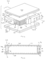
Fig. 1 is an exploded perspective view of a battery module including a battery module housing not according to the invention and a stack of electrochemical cells disposed in the housing. -
Fig. 2 is a cross-sectional view of the battery module housing as seen across line 2-2 ofFig. 1 . -
Fig. 3 is a cross-sectional view of an electrochemical cell. -
Fig. 4 is a cross-sectional view of the battery module housing as seen across line 4-4 ofFig. 1 . -
Fig. 5 is a cross-sectional view of an alternative embodiment battery module housing as seen across line 4-4 ofFig. 1 . -
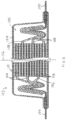
Fig. 6 is an exploded perspective view of a battery module according to the invention and including a battery module housing and a stack of electrochemical cells disposed in the housing. -
Fig. 7 is a cross-sectional view of the battery module housing as seen across line 7-7 ofFig. 6 . - Referring to
Figs. 1 and 2 , a battery module 1 is an energy storage device that includeselectrochemical cells 102 that are electrically interconnected and stored in an organized manner within abattery module housing 2. Thecells 102 are arranged within themodule housing 2 by stacking. Within thebattery module housing 2,cells 102 are electrically connected in series or in parallel. Several battery modules 1 may be disposed in a battery pack housing (not shown) to form a battery pack, and within the battery pack housing, the battery modules 1 are electrically connected in series or in parallel. Thebattery module housing 2 has characteristics of both a prismatic design and a pouch design, as described in detail below. - Referring to
Fig. 3 , eachcell 102 includes acell housing 104 and anelectrode assembly 105 that is sealed within thecell housing 104. Thecell housing 104 is a pouch-type housing formed of a metal foil laminated between thin plastic layers to form a thin film that is folded and sealed in the form of a flexible pouch. In the illustrated embodiment, thecell housing 104 has a low profile, rectangular shape but is not limited to this configuration. - The
electrode assembly 105 disposed in thecell 102 includes a series of stacked individual positive electrode plates (e.g., positive electrodes) 106 alternating with individual negative electrode plates (e.g., negative electrodes) 108 and separated by an intermediate separator plate (e.g., separator) 110. Thepositive electrodes 106, thenegative electrodes 108 and theseparators 110 form a cell stack that is aligned along anelectrode stacking axis 112. - The positive and
negative electrodes positive electrode 106 includes a first substrate (not shown) formed of a first electrically-conductive material such as copper. In addition, thepositive electrode 106 includes a first active material (not shown) such as graphite disposed on at least one side of the first substrate. The first active material is provided on the first substrate for example in a printing process. - The
negative electrode 108 includes a second substrate (not shown) formed of a second electrically-conductive material such as aluminum. In addition, thenegative electrode 108 includes a second active material (not shown) such as a lithiated metal oxide coating disposed on at least one side of the second substrate. The second active material is provided on the second substrate for example in a printing process. - The
separator 110 is a permeable membrane that functions to keep the positive andnegative electrodes cell 102. Theseparator 110 is formed of an electrically insulating material such as a tri-layer polypropylene-polyethylene-polypropylene membrane. - Referring again to
Figs. 1 and 2 , thecells 102 are arranged in an one, two or three dimensional array within thebattery module housing 2, for example in an aligned, stacked arrangement referred to ascell stack 114. Within thecell stack 114, a stacking direction of thecells 102 is parallel to theelectrode stacking axis 112. - The
battery module housing 2 includes aframe 4, afirst cover element 60 and asecond cover element 80 that cooperate to form a closed, sealed container that houses thecell stack 114. - The
frame 4 is a rigid, rectangular, tubular structure that surrounds (e.g., completely encircles) a circumference of thecell stack 114. Theframe 4 includes fourbeam elements 5a, 5b, 5c, 5d connected at opposed ends to form a wall structure that is open at each end (e.g., to form closed section). Theframe 4 has aninner surface 6 that faces thecell stack 114, and anouter surface 8 that is opposed to theinner surface 6. Theframe 4 includes afirst edge 10 that joins theinner surface 6 to theouter surface 8 at oneend 116 of thecell stack 114, and asecond edge 12 that joins theinner surface 6 to theouter surface 8 at anopposed end 118 of thecell stack 114. - In some embodiments according to the invention the
frame 4 is formed of an electrically non-conductive plastic. In other embodiments, theframe 4 is formed of metal. Theframe 4 is sufficiently rigid to physically support thecell stack 114 and retain thecell stack 114 in a desired position and orientation during use. In addition, theframe 4 is sufficiently rigid to prevent deformation of thecells 102 within thecell stack 114 due to impacts which may occur in the course of normal handling and use, as well as during extreme conditions such as can occur if the battery module 1 is dropped. - The
frame 4 is thin walled in that a thickness t of theframe 4 is small relative to both a height h of theframe 4 and a length L of a beam 5 (or alternatively, of a circumference of the frame 4), where the frame thickness t corresponds to a distance between the frameinner surface 6 and the frameouter surface 8, the frame height h corresponds to a distance between thefirst edge 10 and thesecond edge 12, and the beam length L is measured in a direction transverse to the thickness and height directions. The frame height h is set to correspond to, or be slightly greater than, a height of thecell stack 114. - The first and
second cover elements first cover element 60 is formed of a metal foil laminate material, and overlies the oneend 116 of thecell stack 114. Thefirst cover element 60 has a size and shape that corresponds to the size and shape defined by thefirst edge 10 of theframe 4. Theperipheral edge 66 of thefirst cover element 60 is sealed to thefirst edge 10 of theframe 4 along the entirety of theperipheral edge 66 of thefirst cover element 60. For example, in some embodiments, a heating element can be used to form aseal line 68 that joins thefirst cover element 60 to the framefirst edge 10. Theseal line 68 extends along the entire length of thefirst edge 10 to form a closed loop, whereby thefirst cover element 60 closes and seals the one end of theframe 4. - Similarly, the
second cover element 80 is formed of a metal foil laminate material, and overlies theopposed end 118 of thecell stack 114. Thesecond cover element 80 has a size and shape that corresponds to the size and shape defined by thesecond edge 12 of theframe 4. Aperipheral edge 86 of thesecond cover element 80 is sealed to thesecond edge 12 of theframe 4 along the entirety of theperipheral edge 86 of thesecond cover element 80. For example, in some embodiments, a heating element can be used to form aseal line 88 that joins thesecond cover element 80 to the framesecond edge 12. Theseal line 88 extends along the entire length of thesecond edge 12 to form a closed loop, whereby thesecond cover element 80 closes and seals the opposed end of theframe 4. - The metal foil laminate material is a multi-layer material that includes a central layer of metal foil, for example aluminum foil, that is sandwiched between a layer of polyamide and a layer of polypropylene. In one example, the metal foil laminate material may have the following three layers which are joined by a thin adhesive between adjacent layers: oriented nylon/aluminum foil/polypropylene. In another example, the metal foil laminate material may have the following four layers which are joined by a thin adhesive between adjacent layers: polyethylene terephthalate/oriented nylon/aluminum foil/polypropylene. Due to this construction, the metal foil laminate material is a flexible sheet. By providing the
cover elements frame 4, arranged so that the cover elements lie transverse to the cell and electrode stacking directions (e.g., transverse to the electrode stacking axis 112), the battery module 1 is configured to accommodate changes in cell dimension ("cell growth") that occurs during cell operation, whereby cell damage can be avoided which sometimes occurs when cells are stored in a completely rigid housing. - Since the first and
second cover elements frame 4, themodule housing 2 defines a sealed interior space 3. In some embodiments, the interior space 3 of themodule housing 2 is at a pressure that is less than atmospheric pressure. By providing a vacuum within themodule housing 2, the structural integrity of the battery module 1 may be improved relative to a similar structure that is not under vacuum. - The
frame 4 may include valved ports that are configured to permit fluid flow through theframe 4 between the frame inner andouter surfaces frame 4 may include a degasvalved port 26 and/or an electrolyte fillvalved port 28. Thevalved ports port battery module housing 2 and the exterior, and when theport battery module housing 2 and the exterior. - The
frame 4 may include at least one sensor that is configured to detect an operating property of at least onecell 102 of thecell stack 114. For example, theframe 4 may include avoltage sensor 32 for detecting the charge state of acell 102 or of thecell stack 114, atemperature sensor 34 for detecting a temperature of acell 102 of thecell stack 112, and/or other appropriate sensors that facilitate monitoring and/or control of thecells 102 within thebattery module housing 2. - Referring to
Figs. 1 and4 , in some embodiments, theframe 4 includes first and second electricallyconductive terminals terminals first end 37 that protrudes inward from theinner surface 6 of theframe 4 and has an electrical connection with one of thepositive electrode 106 and thenegative electrode 108 of at least onecell 102. Theterminals second end 39 that protrudes outward from theouter surface 8 of theframe 4 to permit electrical connection to an external structure. In other embodiments, the frame 4' does not include theterminals tabs 135 that protrude from one of thepositive electrode 106 and thenegative electrode 108 of at least onecell 102. The terminal opening 136 includes a seal such as agasket 137 that prevents fluid flow through the terminal opening 136. - The
frame 4 may include one or more integral mounting features 29 that are configured to allow theframe 4 to be secured to a support structure. In the illustrated embodiment, the integral mountingfeature 29 includes aboss 30 that protrudes outward from the frameouter surface 8, and a throughhole 31 centered within theboss 30 that extends between the first andsecond edges hole 31 is configured to receive a fastener (not shown) such as a screw. - The
frame 4 may include one ormore cooling channels 40 that extends between a firstcooling channel opening 42 and a secondcooling channel opening 44. The first and secondcooling channel openings frame 4, i.e., at theouter surface 8, and the coolingchannel 40 defines a fluid flow pathway within theframe 4. The coolingchannel 40 is configured to receive fluid such as air or a liquid coolant, and the fluid may flow through thechannel 40 in a passive or actively-driven manner. - Referring to
Figs. 6 and 7 , thebattery module housing 202 according to the invention includes features in common with thebattery module housing 2 illustrated inFig. 1 , and common elements are referred to with common reference numbers. Thebattery module housing 202 shown inFig. 6 differs from the earlier-described embodiment in that it includes alterative first andsecond cover elements second cover elements second edges peripheral edges 266, 286 of the first andsecond cover elements outer surface 8 of theframe 4. In particular, the first andsecond cover elements frame 4 alongseal lines 268, 288 that extend about the circumference of theframe 4 so as to form a closed loop. - Although the
cells 102 described herein are pouch-type cells in which eachcell 102 includes several positive and negative electrode pairs in stacked arrangement, thecells 102 are not limited to this electrode arrangement. For example, in some embodiments, thecell 102 may include a single, elongated electrode pair that is rolled to provide a "jelly roll" electrode arrangement, and housed in a cell housing. In other embodiments, eachcell 102 has a single electrode pair separated by a separator and arranged in a stacked configuration. The single electrode pair may be housed in a cell housing, for example, a pouch type housing or a pouch-prismatic hybrid housing. Alternatively, the single electrode pair may be housing-free, with the electrodes serving as both the housing and the cell terminals. - Although the
cells 102 described herein are pouch-type cells having a metal foillaminate cell housing 104 arranged to form a low profile, flexible pouch, thebattery module housing 2 can accommodate cells having other types of cell housings, including prismatic and cylindrical.
Claims (9)
- A battery module (1) that includes a cell stack (114) and a battery module housing (2) that receives and supports electrochemical cells (102) arranged in the cell stack (114), each cell (102) disposed in a cell housing (104), comprising a positive electrode (106), a negative electrode (108) and a separator (110), where the separator (110) is sandwiched between the positive electrode (106) and the negative electrode (108) and prevents physical contact between the positive electrode (106) and the negative electrode (108),
the battery module housing (2) comprising:a rigid frame (4) formed of an electrically non-conductive plastic or metal, that is rigid to physically support the cell stack (114), retain the cell stack (114) in a desired position and orientation during use, and prevent deformation of the cells (102) within the cell stack (114) due to impacts in the course of normal handling and use, and surrounds a circumference of the cell stack (114), the frame (4) having an inner surface (6) that faces the cell stack (114), an outer surface (8) that is opposed to the inner surface (6), a first edge (10) that joins the inner surface (6) to the outer surface (8) at one end of the cell stack (114) and includes a flat surface, and a second edge (12) that joins the inner surface (6) to the outer surface (8) at an other end of the cell stack (114) and includes a flat surface, wherein a first cover element (260) formed of a flexible metal foil laminate sheet, the first cover element (260) that overlies the one end of the cell stack (114) and a peripheral edge (266) of the first cover element (260) being joined to the frame (4) along the entirety of the peripheral edge (266) of the first cover element (260), anda second cover element (280) formed of a flexible metal foil laminate sheet, the second cover element (280) that overlies the other end of the cell stack (114), a peripheral edge (286) of the second cover element (280) being joined to the frame (4) along the entirety of the peripheral edge (286) of the second cover element (280),whereinthe first and second cover elements (260, 280) are dimensioned so as to extend beyond the first and second edges (10, 12) of the frame (4), whereby the peripheral edges (266, 286) of the first and second cover elements (260, 280) overlie and are sealed to the outer surface (8) of the frame (4),the first and second cover elements (260, 280) are joined to the frame (4) along seal lines (268, 288) that extend about the circumference of the frame (4) so as to form a closed loop,the flexible metal foil laminate sheet is a multi-layer sheet that includes a central layer of metal foil that is sandwiched between a layer of polyamide and a layer of polypropylene, or the flexible metal foil laminate sheet has three layers of oriented nylon/aluminum foil/polypropylene or four layers of polyethylene terephthalate/oriented nylon/aluminum foil/polypropylene, that are joined by a thin adhesive between adjacent layers,the first cover element (260) is heat sealed to the frame (4) along the entirety of the peripheral edge (266) of the first cover element (260), andthe second cover element (280) is heat sealed to the frame (4) along the entirety of the peripheral edge (286) of the second cover element (280),whereby the first cover element (260), the second cover element (280) and the frame (4) cooperate to form a heat sealed module housing (2) for containing the cell stack (114). - The battery module (1) of claim 1, wherein an interior space (3) of the module housing (2) is at a pressure that is less than atmospheric pressure.
- The battery module (1) of claim 1, wherein the frame (4) comprises at least one valved port (26, 28) that is configured to permit fluid flow through the frame (4) when the valved port (26, 28) is in an open configuration, and that is configured to prevent fluid flow through the frame (4) when the valved port (26, 28) is in a closed configuration, wherein the valved port (26, 28) is a degas valved port (26) and/or an electrolyte fill valved port (28).
- The battery module (1) of claim 1, wherein the frame (4) comprises at least one sensor (32, 34) that is configured to detect an operating property of at least one cell (102) of the cell stack (114).
- The battery module (1) of claim 1, wherein the frame (4) comprises an electrically conductive terminal (36, 38), the terminal (36, 38) including a first end (37) that protrudes inward from the inner surface (6) of the frame (4) and is in electrical contact with one of the positive electrode (106) and the negative electrode (108) of at least one cell (102), the terminal (36, 38) including a second end (39) that protrudes outward from the outer surface (8) of the frame (4).
- The battery module (1) of claim 1, wherein the frame (4) comprises integral mounting features (29) that are configured to allow the frame (4) to be secured to a support structure.
- The battery module (1) of claim 1, wherein the frame (4) comprisesa terminal opening (136) configured to permit pass through of a terminal (36, 38) that is electrically connected to at least one cell (102), anda seal (137) disposed in the terminal opening (136) configured to prevent fluid flow between the terminal (36, 38) and the terminal opening (136).
- The battery module (1) of claim 1, wherein the frame (4) comprises a first cooling channel opening (42) and a second cooling channel opening (44), open to the exterior of the frame (4) at the outer surface (8), and a cooling channel (40) that extends between the first cooling channel opening (42) and the second cooling channel opening (44), the cooling channel (40) defining a fluid flow pathway within the frame (4) for receiving fluid flowing through the cooling channel (40) in a passive or actively-driven manner.
- The battery module (1) of any one of claims 1 to 8, wherein the frame (4) is formed of metal.
Applications Claiming Priority (2)
| Application Number | Priority Date | Filing Date | Title |
|---|---|---|---|
| US15/832,440 US10734618B2 (en) | 2017-12-05 | 2017-12-05 | Prismatic-pouch hybrid battery module |
| PCT/EP2018/082181 WO2019110317A1 (en) | 2017-12-05 | 2018-11-22 | Prismatic-pouch hybrid battery module |
Publications (2)
| Publication Number | Publication Date |
|---|---|
| EP3721488A1 EP3721488A1 (en) | 2020-10-14 |
| EP3721488B1 true EP3721488B1 (en) | 2024-09-18 |
Family
ID=64572314
Family Applications (1)
| Application Number | Title | Priority Date | Filing Date |
|---|---|---|---|
| EP18812090.1A Active EP3721488B1 (en) | 2017-12-05 | 2018-11-22 | Prismatic-pouch hybrid battery module |
Country Status (6)
| Country | Link |
|---|---|
| US (1) | US10734618B2 (en) |
| EP (1) | EP3721488B1 (en) |
| JP (1) | JP6952900B2 (en) |
| KR (1) | KR20200095536A (en) |
| CN (1) | CN111656553A (en) |
| WO (1) | WO2019110317A1 (en) |
Families Citing this family (9)
| Publication number | Priority date | Publication date | Assignee | Title |
|---|---|---|---|---|
| DE102019128924A1 (en) * | 2019-10-25 | 2021-04-29 | Audi Ag | Battery module for a high-voltage battery and method for assembling such a battery module |
| KR102473125B1 (en) * | 2019-11-25 | 2022-11-30 | 주식회사 엘지에너지솔루션 | Battery module and battery pack including the same |
| CN113711425B (en) * | 2019-12-20 | 2024-09-06 | 松下知识产权经营株式会社 | Battery |
| CN113285149A (en) * | 2020-02-18 | 2021-08-20 | 比亚迪股份有限公司 | Battery, battery module, battery pack and electric vehicle |
| CN115461919B (en) * | 2020-06-12 | 2024-03-12 | 宁德新能源科技有限公司 | Batteries and electrical devices |
| JP7337115B2 (en) | 2021-04-05 | 2023-09-01 | プライムプラネットエナジー&ソリューションズ株式会社 | storage module |
| EP4539209A3 (en) | 2021-09-27 | 2025-07-30 | QuantumScape Battery, Inc. | Electrochemical stack and method of assembly thereof |
| DE102022107471B3 (en) | 2022-03-30 | 2023-04-20 | Dr. Ing. H.C. F. Porsche Aktiengesellschaft | Battery cell and method for its manufacture |
| DE102023204259A1 (en) | 2023-05-09 | 2024-11-14 | Volkswagen Aktiengesellschaft | battery cell |
Citations (1)
| Publication number | Priority date | Publication date | Assignee | Title |
|---|---|---|---|---|
| JPH10112296A (en) * | 1996-10-07 | 1998-04-28 | Sony Corp | Secondary battery and method of manufacturing the same |
Family Cites Families (24)
| Publication number | Priority date | Publication date | Assignee | Title |
|---|---|---|---|---|
| CN1180506C (en) | 1999-03-26 | 2004-12-15 | 松下电器产业株式会社 | laminated sheet packaged battery |
| JP3729164B2 (en) * | 2002-08-05 | 2005-12-21 | 日産自動車株式会社 | Automotive battery |
| US20040067416A1 (en) | 2002-10-07 | 2004-04-08 | Maclean Gregory K. | Protective frame for rechargeable battery cells |
| KR100599795B1 (en) * | 2004-06-29 | 2006-07-12 | 삼성에스디아이 주식회사 | Secondary battery |
| US8029927B2 (en) | 2005-03-22 | 2011-10-04 | Blue Spark Technologies, Inc. | Thin printable electrochemical cell utilizing a “picture frame” and methods of making the same |
| US20090206096A1 (en) * | 2005-05-17 | 2009-08-20 | Toyo Seikan Kaisha, Ltd. | Three-piece square can and method of manufacturing the same |
| JP2008146963A (en) | 2006-12-08 | 2008-06-26 | Sony Corp | Nonaqueous electrolyte secondary battery separator, nonaqueous electrolyte secondary battery, and battery pack |
| JP4766057B2 (en) * | 2008-01-23 | 2011-09-07 | ソニー株式会社 | Nonaqueous electrolyte battery and method for producing nonaqueous electrolyte battery |
| DE102009035457A1 (en) * | 2009-07-31 | 2011-02-03 | Daimler Ag | Battery, in particular vehicle battery |
| JP5537111B2 (en) * | 2009-09-30 | 2014-07-02 | 株式会社東芝 | Secondary battery device |
| EP2325917B1 (en) * | 2009-10-21 | 2014-03-12 | Samsung SDI Co., Ltd. | Battery assembly |
| US8518569B2 (en) | 2010-03-01 | 2013-08-27 | Apple Inc. | Integrated frame battery cell |
| US8673473B2 (en) * | 2010-08-10 | 2014-03-18 | GM Global Technology Operations LLC | Integrated cooling fin and frame |
| US8835037B2 (en) | 2012-02-01 | 2014-09-16 | Corvus Energy Ltd. | Battery cell carrier |
| JP6171605B2 (en) * | 2013-06-18 | 2017-08-02 | 株式会社デンソー | Battery unit |
| KR102030112B1 (en) * | 2013-11-22 | 2019-10-08 | 삼성에스디아이 주식회사 | Battery pack |
| FR3023416A3 (en) | 2014-07-04 | 2016-01-08 | Renault Sas | BATTERY MODULE WITH SIMPLIFIED ASSEMBLY |
| DE102014117547B4 (en) * | 2014-11-28 | 2016-08-04 | Technische Universität München | Housing for a cell stack of a battery and method for producing such |
| DE102015202894A1 (en) * | 2015-02-18 | 2016-08-18 | Robert Bosch Gmbh | battery cell |
| KR102065102B1 (en) | 2015-09-02 | 2020-01-10 | 주식회사 엘지화학 | A battery module having an improved cooling structure |
| US10062882B2 (en) * | 2015-10-16 | 2018-08-28 | Bosch Battery Systems Llc | Force generating assembly for a battery pack |
| JP6861016B2 (en) * | 2015-11-19 | 2021-04-21 | 三洋化成工業株式会社 | Lithium ion battery |
| WO2017140623A1 (en) | 2016-02-17 | 2017-08-24 | Robert Bosch Gmbh | Single electrode-pair battery |
| KR102202417B1 (en) * | 2016-02-22 | 2021-01-12 | 주식회사 엘지화학 | The cartridge, Battery module including the cartridge, Battery pack |
-
2017
- 2017-12-05 US US15/832,440 patent/US10734618B2/en active Active
-
2018
- 2018-11-22 KR KR1020207019389A patent/KR20200095536A/en not_active Ceased
- 2018-11-22 EP EP18812090.1A patent/EP3721488B1/en active Active
- 2018-11-22 JP JP2020530339A patent/JP6952900B2/en active Active
- 2018-11-22 WO PCT/EP2018/082181 patent/WO2019110317A1/en not_active Ceased
- 2018-11-22 CN CN201880088539.3A patent/CN111656553A/en active Pending
Patent Citations (1)
| Publication number | Priority date | Publication date | Assignee | Title |
|---|---|---|---|---|
| JPH10112296A (en) * | 1996-10-07 | 1998-04-28 | Sony Corp | Secondary battery and method of manufacturing the same |
Also Published As
| Publication number | Publication date |
|---|---|
| JP2021506062A (en) | 2021-02-18 |
| US10734618B2 (en) | 2020-08-04 |
| CN111656553A (en) | 2020-09-11 |
| KR20200095536A (en) | 2020-08-10 |
| JP6952900B2 (en) | 2021-10-27 |
| WO2019110317A1 (en) | 2019-06-13 |
| US20190173065A1 (en) | 2019-06-06 |
| EP3721488A1 (en) | 2020-10-14 |
Similar Documents
| Publication | Publication Date | Title |
|---|---|---|
| EP3721488B1 (en) | Prismatic-pouch hybrid battery module | |
| JP6713547B2 (en) | Multi-cavity battery module | |
| CN103098256B (en) | Pouch case and battery pack including same | |
| KR102618844B1 (en) | Lead tabs for battery terminals | |
| US9460862B2 (en) | Electric storage cell, electric storage apparatus, and vehicle having electric storage apparatus | |
| EP3391430B1 (en) | Through-wall current collector for a pouch cell | |
| KR102681944B1 (en) | Mechanically fixed wall-penetrating current collector | |
| US12476336B2 (en) | Electrochemical element and corresponding battery | |
| JP4784067B2 (en) | Power storage module | |
| US20170288194A1 (en) | Electricity storage device | |
| WO2017140623A1 (en) | Single electrode-pair battery | |
| EP4697468A1 (en) | Battery module | |
| CN120784531A (en) | secondary batteries |
Legal Events
| Date | Code | Title | Description |
|---|---|---|---|
| STAA | Information on the status of an ep patent application or granted ep patent |
Free format text: STATUS: UNKNOWN |
|
| STAA | Information on the status of an ep patent application or granted ep patent |
Free format text: STATUS: THE INTERNATIONAL PUBLICATION HAS BEEN MADE |
|
| PUAI | Public reference made under article 153(3) epc to a published international application that has entered the european phase |
Free format text: ORIGINAL CODE: 0009012 |
|
| STAA | Information on the status of an ep patent application or granted ep patent |
Free format text: STATUS: REQUEST FOR EXAMINATION WAS MADE |
|
| 17P | Request for examination filed |
Effective date: 20200706 |
|
| AK | Designated contracting states |
Kind code of ref document: A1 Designated state(s): AL AT BE BG CH CY CZ DE DK EE ES FI FR GB GR HR HU IE IS IT LI LT LU LV MC MK MT NL NO PL PT RO RS SE SI SK SM TR |
|
| AX | Request for extension of the european patent |
Extension state: BA ME |
|
| DAV | Request for validation of the european patent (deleted) | ||
| DAX | Request for extension of the european patent (deleted) | ||
| STAA | Information on the status of an ep patent application or granted ep patent |
Free format text: STATUS: EXAMINATION IS IN PROGRESS |
|
| 17Q | First examination report despatched |
Effective date: 20210701 |
|
| REG | Reference to a national code |
Ref country code: DE Ref legal event code: R079 Free format text: PREVIOUS MAIN CLASS: H01M0002020000 Ipc: H01M0050220000 Ref document number: 602018074543 Country of ref document: DE |
|
| GRAP | Despatch of communication of intention to grant a patent |
Free format text: ORIGINAL CODE: EPIDOSNIGR1 |
|
| STAA | Information on the status of an ep patent application or granted ep patent |
Free format text: STATUS: GRANT OF PATENT IS INTENDED |
|
| RIC1 | Information provided on ipc code assigned before grant |
Ipc: H01M 50/296 20210101ALI20240403BHEP Ipc: H01M 50/211 20210101ALI20240403BHEP Ipc: H01M 50/105 20210101ALI20240403BHEP Ipc: H01M 10/6556 20140101ALI20240403BHEP Ipc: H01M 10/48 20060101ALI20240403BHEP Ipc: H01M 10/647 20140101ALI20240403BHEP Ipc: H01M 50/282 20210101ALI20240403BHEP Ipc: H01M 50/28 20210101ALI20240403BHEP Ipc: H01M 50/22 20210101AFI20240403BHEP |
|
| INTG | Intention to grant announced |
Effective date: 20240422 |
|
| GRAS | Grant fee paid |
Free format text: ORIGINAL CODE: EPIDOSNIGR3 |
|
| GRAA | (expected) grant |
Free format text: ORIGINAL CODE: 0009210 |
|
| STAA | Information on the status of an ep patent application or granted ep patent |
Free format text: STATUS: THE PATENT HAS BEEN GRANTED |
|
| AK | Designated contracting states |
Kind code of ref document: B1 Designated state(s): AL AT BE BG CH CY CZ DE DK EE ES FI FR GB GR HR HU IE IS IT LI LT LU LV MC MK MT NL NO PL PT RO RS SE SI SK SM TR |
|
| REG | Reference to a national code |
Ref country code: GB Ref legal event code: FG4D |
|
| REG | Reference to a national code |
Ref country code: CH Ref legal event code: EP |
|
| REG | Reference to a national code |
Ref country code: DE Ref legal event code: R096 Ref document number: 602018074543 Country of ref document: DE |
|
| REG | Reference to a national code |
Ref country code: IE Ref legal event code: FG4D |
|
| REG | Reference to a national code |
Ref country code: LT Ref legal event code: MG9D |
|
| PG25 | Lapsed in a contracting state [announced via postgrant information from national office to epo] |
Ref country code: NO Free format text: LAPSE BECAUSE OF FAILURE TO SUBMIT A TRANSLATION OF THE DESCRIPTION OR TO PAY THE FEE WITHIN THE PRESCRIBED TIME-LIMIT Effective date: 20241218 |
|
| PG25 | Lapsed in a contracting state [announced via postgrant information from national office to epo] |
Ref country code: GR Free format text: LAPSE BECAUSE OF FAILURE TO SUBMIT A TRANSLATION OF THE DESCRIPTION OR TO PAY THE FEE WITHIN THE PRESCRIBED TIME-LIMIT Effective date: 20241219 Ref country code: FI Free format text: LAPSE BECAUSE OF FAILURE TO SUBMIT A TRANSLATION OF THE DESCRIPTION OR TO PAY THE FEE WITHIN THE PRESCRIBED TIME-LIMIT Effective date: 20240918 |
|
| PG25 | Lapsed in a contracting state [announced via postgrant information from national office to epo] |
Ref country code: BG Free format text: LAPSE BECAUSE OF FAILURE TO SUBMIT A TRANSLATION OF THE DESCRIPTION OR TO PAY THE FEE WITHIN THE PRESCRIBED TIME-LIMIT Effective date: 20240918 |
|
| PG25 | Lapsed in a contracting state [announced via postgrant information from national office to epo] |
Ref country code: LV Free format text: LAPSE BECAUSE OF FAILURE TO SUBMIT A TRANSLATION OF THE DESCRIPTION OR TO PAY THE FEE WITHIN THE PRESCRIBED TIME-LIMIT Effective date: 20240918 |
|
| PG25 | Lapsed in a contracting state [announced via postgrant information from national office to epo] |
Ref country code: HR Free format text: LAPSE BECAUSE OF FAILURE TO SUBMIT A TRANSLATION OF THE DESCRIPTION OR TO PAY THE FEE WITHIN THE PRESCRIBED TIME-LIMIT Effective date: 20240918 |
|
| REG | Reference to a national code |
Ref country code: NL Ref legal event code: MP Effective date: 20240918 |
|
| PG25 | Lapsed in a contracting state [announced via postgrant information from national office to epo] |
Ref country code: RS Free format text: LAPSE BECAUSE OF FAILURE TO SUBMIT A TRANSLATION OF THE DESCRIPTION OR TO PAY THE FEE WITHIN THE PRESCRIBED TIME-LIMIT Effective date: 20241218 |
|
| PG25 | Lapsed in a contracting state [announced via postgrant information from national office to epo] |
Ref country code: RS Free format text: LAPSE BECAUSE OF FAILURE TO SUBMIT A TRANSLATION OF THE DESCRIPTION OR TO PAY THE FEE WITHIN THE PRESCRIBED TIME-LIMIT Effective date: 20241218 Ref country code: NO Free format text: LAPSE BECAUSE OF FAILURE TO SUBMIT A TRANSLATION OF THE DESCRIPTION OR TO PAY THE FEE WITHIN THE PRESCRIBED TIME-LIMIT Effective date: 20241218 Ref country code: LV Free format text: LAPSE BECAUSE OF FAILURE TO SUBMIT A TRANSLATION OF THE DESCRIPTION OR TO PAY THE FEE WITHIN THE PRESCRIBED TIME-LIMIT Effective date: 20240918 Ref country code: HR Free format text: LAPSE BECAUSE OF FAILURE TO SUBMIT A TRANSLATION OF THE DESCRIPTION OR TO PAY THE FEE WITHIN THE PRESCRIBED TIME-LIMIT Effective date: 20240918 Ref country code: GR Free format text: LAPSE BECAUSE OF FAILURE TO SUBMIT A TRANSLATION OF THE DESCRIPTION OR TO PAY THE FEE WITHIN THE PRESCRIBED TIME-LIMIT Effective date: 20241219 Ref country code: FI Free format text: LAPSE BECAUSE OF FAILURE TO SUBMIT A TRANSLATION OF THE DESCRIPTION OR TO PAY THE FEE WITHIN THE PRESCRIBED TIME-LIMIT Effective date: 20240918 Ref country code: BG Free format text: LAPSE BECAUSE OF FAILURE TO SUBMIT A TRANSLATION OF THE DESCRIPTION OR TO PAY THE FEE WITHIN THE PRESCRIBED TIME-LIMIT Effective date: 20240918 |
|
| REG | Reference to a national code |
Ref country code: AT Ref legal event code: MK05 Ref document number: 1725474 Country of ref document: AT Kind code of ref document: T Effective date: 20240918 |
|
| PG25 | Lapsed in a contracting state [announced via postgrant information from national office to epo] |
Ref country code: NL Free format text: LAPSE BECAUSE OF FAILURE TO SUBMIT A TRANSLATION OF THE DESCRIPTION OR TO PAY THE FEE WITHIN THE PRESCRIBED TIME-LIMIT Effective date: 20240918 |
|
| PG25 | Lapsed in a contracting state [announced via postgrant information from national office to epo] |
Ref country code: IS Free format text: LAPSE BECAUSE OF FAILURE TO SUBMIT A TRANSLATION OF THE DESCRIPTION OR TO PAY THE FEE WITHIN THE PRESCRIBED TIME-LIMIT Effective date: 20250118 Ref country code: PT Free format text: LAPSE BECAUSE OF FAILURE TO SUBMIT A TRANSLATION OF THE DESCRIPTION OR TO PAY THE FEE WITHIN THE PRESCRIBED TIME-LIMIT Effective date: 20250120 |
|
| PG25 | Lapsed in a contracting state [announced via postgrant information from national office to epo] |
Ref country code: SM Free format text: LAPSE BECAUSE OF FAILURE TO SUBMIT A TRANSLATION OF THE DESCRIPTION OR TO PAY THE FEE WITHIN THE PRESCRIBED TIME-LIMIT Effective date: 20240918 Ref country code: RO Free format text: LAPSE BECAUSE OF FAILURE TO SUBMIT A TRANSLATION OF THE DESCRIPTION OR TO PAY THE FEE WITHIN THE PRESCRIBED TIME-LIMIT Effective date: 20240918 |
|
| PG25 | Lapsed in a contracting state [announced via postgrant information from national office to epo] |
Ref country code: ES Free format text: LAPSE BECAUSE OF FAILURE TO SUBMIT A TRANSLATION OF THE DESCRIPTION OR TO PAY THE FEE WITHIN THE PRESCRIBED TIME-LIMIT Effective date: 20240918 |
|
| PG25 | Lapsed in a contracting state [announced via postgrant information from national office to epo] |
Ref country code: AT Free format text: LAPSE BECAUSE OF FAILURE TO SUBMIT A TRANSLATION OF THE DESCRIPTION OR TO PAY THE FEE WITHIN THE PRESCRIBED TIME-LIMIT Effective date: 20240918 Ref country code: EE Free format text: LAPSE BECAUSE OF FAILURE TO SUBMIT A TRANSLATION OF THE DESCRIPTION OR TO PAY THE FEE WITHIN THE PRESCRIBED TIME-LIMIT Effective date: 20240918 |
|
| PG25 | Lapsed in a contracting state [announced via postgrant information from national office to epo] |
Ref country code: CZ Free format text: LAPSE BECAUSE OF FAILURE TO SUBMIT A TRANSLATION OF THE DESCRIPTION OR TO PAY THE FEE WITHIN THE PRESCRIBED TIME-LIMIT Effective date: 20240918 Ref country code: PL Free format text: LAPSE BECAUSE OF FAILURE TO SUBMIT A TRANSLATION OF THE DESCRIPTION OR TO PAY THE FEE WITHIN THE PRESCRIBED TIME-LIMIT Effective date: 20240918 |
|
| PG25 | Lapsed in a contracting state [announced via postgrant information from national office to epo] |
Ref country code: IT Free format text: LAPSE BECAUSE OF FAILURE TO SUBMIT A TRANSLATION OF THE DESCRIPTION OR TO PAY THE FEE WITHIN THE PRESCRIBED TIME-LIMIT Effective date: 20240918 Ref country code: SK Free format text: LAPSE BECAUSE OF FAILURE TO SUBMIT A TRANSLATION OF THE DESCRIPTION OR TO PAY THE FEE WITHIN THE PRESCRIBED TIME-LIMIT Effective date: 20240918 |
|
| REG | Reference to a national code |
Ref country code: DE Ref legal event code: R119 Ref document number: 602018074543 Country of ref document: DE |
|
| REG | Reference to a national code |
Ref country code: CH Ref legal event code: PL |
|
| PG25 | Lapsed in a contracting state [announced via postgrant information from national office to epo] |
Ref country code: MC Free format text: LAPSE BECAUSE OF FAILURE TO SUBMIT A TRANSLATION OF THE DESCRIPTION OR TO PAY THE FEE WITHIN THE PRESCRIBED TIME-LIMIT Effective date: 20240918 |
|
| PG25 | Lapsed in a contracting state [announced via postgrant information from national office to epo] |
Ref country code: DK Free format text: LAPSE BECAUSE OF FAILURE TO SUBMIT A TRANSLATION OF THE DESCRIPTION OR TO PAY THE FEE WITHIN THE PRESCRIBED TIME-LIMIT Effective date: 20240918 |
|
| PG25 | Lapsed in a contracting state [announced via postgrant information from national office to epo] |
Ref country code: LU Free format text: LAPSE BECAUSE OF NON-PAYMENT OF DUE FEES Effective date: 20241122 |
|
| REG | Reference to a national code |
Ref country code: CH Ref legal event code: PL |
|
| PG25 | Lapsed in a contracting state [announced via postgrant information from national office to epo] |
Ref country code: CH Free format text: LAPSE BECAUSE OF NON-PAYMENT OF DUE FEES Effective date: 20241130 |
|
| PLBE | No opposition filed within time limit |
Free format text: ORIGINAL CODE: 0009261 |
|
| STAA | Information on the status of an ep patent application or granted ep patent |
Free format text: STATUS: NO OPPOSITION FILED WITHIN TIME LIMIT |
|
| 26N | No opposition filed |
Effective date: 20250619 |
|
| GBPC | Gb: european patent ceased through non-payment of renewal fee |
Effective date: 20241218 |
|
| REG | Reference to a national code |
Ref country code: BE Ref legal event code: MM Effective date: 20241130 |
|
| PG25 | Lapsed in a contracting state [announced via postgrant information from national office to epo] |
Ref country code: SE Free format text: LAPSE BECAUSE OF FAILURE TO SUBMIT A TRANSLATION OF THE DESCRIPTION OR TO PAY THE FEE WITHIN THE PRESCRIBED TIME-LIMIT Effective date: 20240918 |
|
| PG25 | Lapsed in a contracting state [announced via postgrant information from national office to epo] |
Ref country code: DE Free format text: LAPSE BECAUSE OF NON-PAYMENT OF DUE FEES Effective date: 20250603 |
|
| PG25 | Lapsed in a contracting state [announced via postgrant information from national office to epo] |
Ref country code: GB Free format text: LAPSE BECAUSE OF NON-PAYMENT OF DUE FEES Effective date: 20241218 Ref country code: BE Free format text: LAPSE BECAUSE OF NON-PAYMENT OF DUE FEES Effective date: 20241130 |
|
| PG25 | Lapsed in a contracting state [announced via postgrant information from national office to epo] |
Ref country code: FR Free format text: LAPSE BECAUSE OF NON-PAYMENT OF DUE FEES Effective date: 20241130 |
|
| PG25 | Lapsed in a contracting state [announced via postgrant information from national office to epo] |
Ref country code: IE Free format text: LAPSE BECAUSE OF NON-PAYMENT OF DUE FEES Effective date: 20241122 |
|
| PG25 | Lapsed in a contracting state [announced via postgrant information from national office to epo] |
Ref country code: HU Free format text: LAPSE BECAUSE OF FAILURE TO SUBMIT A TRANSLATION OF THE DESCRIPTION OR TO PAY THE FEE WITHIN THE PRESCRIBED TIME-LIMIT; INVALID AB INITIO Effective date: 20181122 |
|
| PG25 | Lapsed in a contracting state [announced via postgrant information from national office to epo] |
Ref country code: CY Free format text: LAPSE BECAUSE OF FAILURE TO SUBMIT A TRANSLATION OF THE DESCRIPTION OR TO PAY THE FEE WITHIN THE PRESCRIBED TIME-LIMIT; INVALID AB INITIO Effective date: 20181122 |