EP3720758B1 - Wheel-carrying member for a vehicle suspension - Google Patents
Wheel-carrying member for a vehicle suspension Download PDFInfo
- Publication number
- EP3720758B1 EP3720758B1 EP18827253.8A EP18827253A EP3720758B1 EP 3720758 B1 EP3720758 B1 EP 3720758B1 EP 18827253 A EP18827253 A EP 18827253A EP 3720758 B1 EP3720758 B1 EP 3720758B1
- Authority
- EP
- European Patent Office
- Prior art keywords
- wheel
- carrying member
- shell element
- insert
- suspension
- Prior art date
- Legal status (The legal status is an assumption and is not a legal conclusion. Google has not performed a legal analysis and makes no representation as to the accuracy of the status listed.)
- Active
Links
Images




Classifications
-
- B—PERFORMING OPERATIONS; TRANSPORTING
- B62—LAND VEHICLES FOR TRAVELLING OTHERWISE THAN ON RAILS
- B62D—MOTOR VEHICLES; TRAILERS
- B62D7/00—Steering linkage; Stub axles or their mountings
- B62D7/18—Steering knuckles; King pins
-
- B—PERFORMING OPERATIONS; TRANSPORTING
- B60—VEHICLES IN GENERAL
- B60G—VEHICLE SUSPENSION ARRANGEMENTS
- B60G2204/00—Indexing codes related to suspensions per se or to auxiliary parts
- B60G2204/10—Mounting of suspension elements
- B60G2204/12—Mounting of springs or dampers
- B60G2204/129—Damper mount on wheel suspension or knuckle
-
- B—PERFORMING OPERATIONS; TRANSPORTING
- B60—VEHICLES IN GENERAL
- B60G—VEHICLE SUSPENSION ARRANGEMENTS
- B60G2204/00—Indexing codes related to suspensions per se or to auxiliary parts
- B60G2204/10—Mounting of suspension elements
- B60G2204/14—Mounting of suspension arms
- B60G2204/148—Mounting of suspension arms on the unsprung part of the vehicle, e.g. wheel knuckle or rigid axle
-
- B—PERFORMING OPERATIONS; TRANSPORTING
- B60—VEHICLES IN GENERAL
- B60G—VEHICLE SUSPENSION ARRANGEMENTS
- B60G2206/00—Indexing codes related to the manufacturing of suspensions: constructional features, the materials used, procedures or tools
- B60G2206/01—Constructional features of suspension elements, e.g. arms, dampers, springs
- B60G2206/013—Constructional features of suspension elements, e.g. arms, dampers, springs with embedded inserts for material reinforcement
-
- B—PERFORMING OPERATIONS; TRANSPORTING
- B60—VEHICLES IN GENERAL
- B60G—VEHICLE SUSPENSION ARRANGEMENTS
- B60G2206/00—Indexing codes related to the manufacturing of suspensions: constructional features, the materials used, procedures or tools
- B60G2206/01—Constructional features of suspension elements, e.g. arms, dampers, springs
- B60G2206/50—Constructional features of wheel supports or knuckles, e.g. steering knuckles, spindle attachments
-
- B—PERFORMING OPERATIONS; TRANSPORTING
- B60—VEHICLES IN GENERAL
- B60G—VEHICLE SUSPENSION ARRANGEMENTS
- B60G2206/00—Indexing codes related to the manufacturing of suspensions: constructional features, the materials used, procedures or tools
- B60G2206/01—Constructional features of suspension elements, e.g. arms, dampers, springs
- B60G2206/70—Materials used in suspensions
- B60G2206/71—Light weight materials
- B60G2206/7101—Fiber-reinforced plastics [FRP]
-
- B—PERFORMING OPERATIONS; TRANSPORTING
- B60—VEHICLES IN GENERAL
- B60G—VEHICLE SUSPENSION ARRANGEMENTS
- B60G2206/00—Indexing codes related to the manufacturing of suspensions: constructional features, the materials used, procedures or tools
- B60G2206/01—Constructional features of suspension elements, e.g. arms, dampers, springs
- B60G2206/70—Materials used in suspensions
- B60G2206/71—Light weight materials
- B60G2206/7104—Thermoplastics
-
- B—PERFORMING OPERATIONS; TRANSPORTING
- B60—VEHICLES IN GENERAL
- B60G—VEHICLE SUSPENSION ARRANGEMENTS
- B60G2206/00—Indexing codes related to the manufacturing of suspensions: constructional features, the materials used, procedures or tools
- B60G2206/01—Constructional features of suspension elements, e.g. arms, dampers, springs
- B60G2206/80—Manufacturing procedures
- B60G2206/81—Shaping
Definitions
- the present invention relates to a wheel-carrying member for a vehicle suspension, that can be used both for the front suspension and for the rear suspension of the vehicle.
- the wheel-carrying member of a vehicle suspension serves for connecting the wheel, via a bearing and a hub, to the suspension linkage, that is, to the assembly of arms or levers of the suspension.
- the wheel-carrying member further provides the seats for the mountings of the brake caliper, for the sensors associated to the wheel (for example, the ABS sensor) and for the shock absorber.
- the wheel-carrying members are provided both in the front and in the rear suspensions and have different geometrical features depending on the type of suspension (for example, McPherson, double wishbone, "multi-link").
- Wheel-carrying members for vehicle suspensions are also known, which members have a hybrid structure, with a body formed by a fibre-reinforced polymeric matrix and with a plurality of metal inserts that are rigidly connected to said polymeric matrix and are used to connect the wheel-carrying member with further components of the vehicle suspension.
- a wheel-carrying member with such a hybrid structure is known, for example, from DE 10 2007 053120 .
- This known solution comprises a body formed by a thermoset polymeric matrix and, therefore, the corresponding manufacturing cycle comprises, among others, a curing step, which involves an increase in the cycle time.
- the shape of the inserts and the way of fixing them to the body are such that the inserts can only work as load transfer elements, and not as load bearing elements, and, thus, do not substantially contribute to the overall strength and stiffness of the wheel-carrying member.
- KR 2015 0065222 discloses a wheel-carrying member for vehicle suspension comprising plate elements made of plastic material reinforced with carbon fiber, which are made separately from each other and subsequently firmly connected to each other by bonding.
- a further aspect of the present invention relates to a method for manufacturing a wheel-carrying member for a vehicle suspension comprising the steps set forth in independent claim 11.
- the invention is based on the idea of providing a wheel-carrying member with a hybrid structure, comprising:
- the wheel-carrying member according to the invention is lighter than a conventional wheel-carrying member made of steel, aluminium or cast iron. Furthermore, by conveniently choosing the geometry of the body, as well as the geometry and the arrangement of the shell element (or of the shell elements), it is possible to provide a wheel-carrying member that fulfils the specific requirements in terms, for example, of mechanical strength, stiffness, etc.
- the use of a thermoplastic material for the polymeric matrix of the body allows speeding up the manufacturing cycle, since no curing step is required.
- the particular shape of the inserts and the way of fixing them to the body of the wheel-carrying member allow to use the inserts not only as load transfer elements but also, and more importantly, as load bearing elements that contribute to the overall strength and stiffness of the wheel-carrying member.
- the body is shaped as a hollow body and has a cross section that is open towards the internal side.
- the body is preferably provided with a plurality of stiffening ribs, which are made in a single piece with the body and are conveniently arranged and sized so as to increase the overall mechanical strength and stiffness of the body, and thus of the wheel-carrying member.
- the at least one shell element formed by a thermoplastic matrix laminate is advantageously obtained by a thermoforming process.
- the geometry and the arrangement of such element(s), the features of each ply (woven or unidirectional fibres), the orientation of the carbon fibres and the type of reinforcement fibres (glass or carbon, long or short) will be selected based on the mechanical requirements for the wheel-carrying member.
- the type of thermoplastic resin will be selected based on the structural and environmental requirements for the wheel-carrying member.
- the body is advantageously made by over-moulding of the composite material on the least one shell element.
- the geometry of the body, the type of resin and the type of reinforcement fibres (glass or carbon, long or short) will be selected based on the mechanical requirements and on the operational environment of the wheel-carrying member.
- the metal inserts are preferably made of aluminium or steel and preferably subjected to a surface pre-treatment (sandblasting, laser treatment, etc.) to increase adhesion with the composite material of the body.
- the inserts preferably have at least one undercut portion which is filled by the injected material of the body, so that the bonding of the joint between the inserts and the body is increased and the overall strength and stiffness characteristics of the wheel-carrying member are improved.
- a wheel-carrying member according to an embodiment of the present invention is generally indicated with 10 and is used herein for supporting a front wheel of a motor vehicle in a McPherson suspension system.
- the use of the wheel-carrying member for a McPherson front suspension is, nevertheless, to be intended purely as a non-limitative example, as the wheel-carrying member according to the present invention can be used in any other type of suspension, be it a front suspension or a rear one.
- the wheel-carrying member 10 has a seat 12 for the mounting of a bearing 14 for supporting the wheel.
- the wheel-carrying member 10 further comprises a mounting portion 16 for the mounting of a shock absorber 18, a mounting portion 20 for the mounting of a brake caliper 22, a mounting portion 24 for the mounting of an oscillating arm (not shown) and a mounting portion 26 for the mounting of a steering arm (not shown).
- the number and the arrangement of the mounting portions may change with respect to what is shown in the drawings.
- the wheel-carrying member 10 would not include the mounting portion 26.
- the wheel-carrying member 10 will include a plurality of mounting portions for the mounting of the plurality of rods/arms of the suspension.
- the wheel-carrying member 10 has a hybrid structure comprising a shell element 28, a body 30 and a plurality of inserts (namely, a pair of inserts 32 for fixing the wheel-carrying member 10 to the shock absorber 18, a pair of inserts 34 for fixing the wheel-carrying member 10 to the brake caliper 22, an insert 36 for connecting the wheel-carrying member 10 to the oscillating arm and an insert 38 for connecting the wheel-carrying member 10 to the steering arm).
- the shell element 28 (which is, in this case, a single shell element) is formed by a laminate with a thermoplastic matrix and is fixed to an external side of the body 30.
- the body 30 is made of a composite material with a fibre-reinforced thermoplastic matrix and is shaped as a hollow body, with a cross section that is open towards the internal side (that is, towards the side that, in the mounted condition of the wheel-carrying member on a vehicle, faces towards the internal side of the vehicle).
- the inserts 32, 34, 36 and 38 are made of metal, for example aluminium or steel.
- the outer shell element 28 is advantageously made by thermoforming process.
- the overall geometry of the shell element, the features of each ply (woven or unidirectional fibres), the orientation of the carbon fibres and the type of reinforcement fibres (glass or carbon, long or short) will be selected based on the mechanical requirements for the wheel-carrying member.
- the type of thermoplastic resin will be selected based on the structural and environmental requirements for the wheel-carrying member.
- the shell element 28 is made by stacking of pre-preg plies, reinforced with unidirectional carbon fibres, directed at 0/45/-45/90 degrees.
- the choice of the four directions indicated above allows for the highest degree of isotropy that can theoretically be obtained with a stacking of plies having unidirectional fibres.
- the shell element 28 is balanced in the direction 45 degrees, so that a coupling effect between bending and torsion, which would occur in case of lack of balance, is avoided.
- the shell element 28 may also be made, for example, by stacking of pre-preg plies with woven carbon fibres.
- the shell element 28 will be formed by a sequence of carbon-fibre (and, possibly, glass-fibre too) pre-preg plies, conveniently configured to maximise the mechanical performances of the component and bear the stresses the component undergoes in use.
- the shell element 28 may have a variable thickness, with a greater thickness in the areas where higher stresses are applied, or, alternatively, a constant thickness with localized reinforcements in the areas where higher stresses are applied.
- the shell element 28 may provide the wheel-carrying member 10 with a greater level of stiffness than the one provided by the body 30.
- the highest stiffness contribution by the shell element 28 is provided in the plane of the ply.
- the shell element 28 provides a certain contribution to stiffness also outside the plane of the ply.
- the body 30 is made of a composite material with a thermoplastic matrix, for example with a polyphthalamide (PPA) or polyamide (PA6, PA66) matrix having mechanical characteristics that are selected based on the performance requirements for the wheel-carrying member. Because of the reduced water absorption tendency of the polyphthalamide, this material is particularly indicated for a component that is exposed, though not directly, to weather, as is the case for a wheel-carrying member.
- PPA polyphthalamide
- PA6, PA66 polyamide
- the same material used for the thermoplastic matrix of the shell element 28 is also used for the thermoplastic matrix of the body 30, so that compatibility issues between the shell element and the body during moulding are avoided.
- the reinforcement fibres of the composite material of the body 30 are, for example, glass fibres, in particular so-called "chopped" glass fibres.
- the body 30 provides the wheel-carrying member 10 with a further amount of stiffness, in addition to the one provided by the shell element 28. In particular, the body 30 provides a contribution to the stiffness outside the plane of the ply.
- the body 30 may be made by over-moulding of the composite material (for example polyphthalamide loaded with glass or carbon, long or short fibres) on the shell element 28 or in a same forming operation (the so-called “one shot” technique) or in a subsequent operation once the ply forming the shell element 28 has been obtained.
- the composite material for example polyphthalamide loaded with glass or carbon, long or short fibres
- the body 30 preferably has a plurality of ribs with a geometry and a thickness that are conveniently defined depending on the stress state to which the wheel-carrying member is subject in use.
- the ribs are made in a single piece with the body 30 and are configured to adhere to the shell element 28 and to the bent edges 40 thereof, if any.
- the inserts 32, 34, 36 and 38 are firmly secured to the body 30, preferably by insert moulding.
- the inserts 32, 34, 36 and 38 may undergo surface pre-treatments (sandblasting, laser treatment, etc.) according to processes that are already well known and therefore will not be described in detail herein.
- the inserts may be conveniently shaped to have undercut portions which are filled by the material of the body 30, in order to improve the bonding of the joint between the inserts and the body.
- the insert 38 for connection of the wheel-carrying member 10 to the steering arm is made, for example, as a conical insert, where the conical pin of a head 42 (shown in Figure 1 ) is intended to be inserted and secured with a nut, the head 42 being coupled to the steering arm by a ball joint.
- a conical insert where the conical pin of the head is accommodated and locked, allows to distribute the steering loads, projecting the exchanged force not only on a radial direction, but also on an axial one.
- FIGs 6 and 7 show in detail the insert 36 used for connection of the wheel-carrying member 10 to the oscillating arm.
- the insert 36 has a seat 44 for accommodating a cylindrical pin head (not shown) that is rigidly connected, for example by press-fitting, threaded connection or riveting, to the oscillating arm.
- the insert 36 forms a protrusion 46 and at least one undercut portion for increasing the contact surface between the metallic material of the insert 36 and the composite material of the body 30 and improving the bonding between the insert and the body (by virtue of the injected material of the body flowing into the undercut portion(s)).
- connection of the wheel-carrying member 10 with the shock absorber 18 is obtained by screwing to the wheel-carrying member, in the region of the inserts 32, a bracket 48 which is rigidly connected, for example by welding, to the body of the shock absorber.
- the inserts 32, 34 and 38 are preferably accommodated in respective sleeves of composite material which are integrally formed by the body 30 and at which the ribs of the body 30 end.
- FIG. 8 to 13 A further embodiment of a wheel-carrying member according to the present invention is shown in Figures 8 to 13 , where parts and elements identical or corresponding to the ones shown in Figures 1 to 7 are indicated with the same reference numbers.
- the wheel-carrying member 10 comprises a body 30 and a number of shell elements 28, which are separate from one another (in the present case, three shell elements indicated with 28', 28" and 28′′′, respectively) and fixed to the body 30 on the external side thereof, that is, on the side facing outwards of the vehicle in the mounted condition of the wheel-carrying member 10 on the vehicle.
- the shell elements 28', 28" and 28'" are positioned in the mounting portion 16 for the shock absorber, in the mounting portion 20 for the brake caliper, and in the mounting portion 26 for the steering arm, respectively.
- the number and the position of the shell elements may change depending on the specific requirements.
- the body 30 is made as a hollow body having across section that opens towards the internal side.
- the bent edges 40 described above with reference to the embodiment of Figures 1 to 7 are formed by the body 30, rather than by the shell element (or by one of the shell elements).
- the body 30 has a ribbed structure with a plurality of ribs 50 (that can be seen in particular in Figure 9 ) formed in a single piece with the body itself.
- the metal inserts in Figures 10 to 12 only the metal inserts 32, 34 and 36, along with a further metal insert 52 - shown in section in Figure 10 - that defines the seat 12 for the mounting of the wheel bearing, are shown in section) have each at least one undercut portion 54 filled by the injected material of the body 30, which allows to improve the bonding between the inserts and the body and increase the overall strength and stiffness characteristics of the wheel-carrying member.
- the wheel-carrying member according to the present invention has a remarkably lower weight than a conventional wheel-carrying member entirely made of metal (such as steel, aluminium or cast iron), without thereby adversely affecting the performances of the wheel-carrying member.
- a convenient design of the geometry and of the structure of the body and of the shell element it is, in fact, possible to provide a wheel-carrying member that is able to fulfil the requirements of the specific application for which the wheel-carrying member is designed.
- the overall geometry of the wheel-carrying member, the number, the arrangement and the configuration of the inserts, as well as the geometry and the internal structure of the shell element (or elements) and of the body, may change depending on the particular application for which the wheel-carrying member is designed.
Landscapes
- Engineering & Computer Science (AREA)
- Chemical & Material Sciences (AREA)
- Combustion & Propulsion (AREA)
- Transportation (AREA)
- Mechanical Engineering (AREA)
- Vehicle Body Suspensions (AREA)
- Laminated Bodies (AREA)
Description
- The present invention relates to a wheel-carrying member for a vehicle suspension, that can be used both for the front suspension and for the rear suspension of the vehicle.
- As is known, the wheel-carrying member of a vehicle suspension serves for connecting the wheel, via a bearing and a hub, to the suspension linkage, that is, to the assembly of arms or levers of the suspension. The wheel-carrying member further provides the seats for the mountings of the brake caliper, for the sensors associated to the wheel (for example, the ABS sensor) and for the shock absorber. In a vehicle, the wheel-carrying members are provided both in the front and in the rear suspensions and have different geometrical features depending on the type of suspension (for example, McPherson, double wishbone, "multi-link").
- Steel, aluminium and cast iron are the materials generally used for this component.
- Wheel-carrying members for vehicle suspensions are also known, which members have a hybrid structure, with a body formed by a fibre-reinforced polymeric matrix and with a plurality of metal inserts that are rigidly connected to said polymeric matrix and are used to connect the wheel-carrying member with further components of the vehicle suspension.
- A wheel-carrying member with such a hybrid structure is known, for example, from
DE 10 2007 053120 . This known solution comprises a body formed by a thermoset polymeric matrix and, therefore, the corresponding manufacturing cycle comprises, among others, a curing step, which involves an increase in the cycle time. In addition, the shape of the inserts and the way of fixing them to the body are such that the inserts can only work as load transfer elements, and not as load bearing elements, and, thus, do not substantially contribute to the overall strength and stiffness of the wheel-carrying member.KR 2015 0065222 - It is an object of the present invention to provide a wheel-carrying member for a vehicle suspension, of the type having a hybrid structure , that is simpler, quicker and cheaper to manufacture and has a higher strength and stiffness than the prior art discussed above.
- This and other objects are fully accomplished according to the invention by virtue of a wheel-carrying member having the features set forth in the attached independent claim 1.
- Advantageous embodiments of the invention are defined in the dependent claims, the subject-matter of which is to be considered as forming an integral part of the following description.
- A further aspect of the present invention relates to a method for manufacturing a wheel-carrying member for a vehicle suspension comprising the steps set forth in independent claim 11.
- In short, the invention is based on the idea of providing a wheel-carrying member with a hybrid structure, comprising:
- a body in a composite material with a fibre-reinforced thermoplastic matrix;
- at least one shell element formed by a laminate with a thermoplastic matrix, said at least one shell element being fixed on an external side of the body, which is a side of the body that, in the mounted condition of the wheel-carrying member on the vehicle, is directed laterally outwards of the vehicle; and
- a plurality of metal inserts for connecting the wheel-carrying member to other components of the suspension or of the vehicle, each metal insert being embedded in the body so as to be firmly connected to the body without the use of adhesive means.
- By virtue of such a structure, the wheel-carrying member according to the invention is lighter than a conventional wheel-carrying member made of steel, aluminium or cast iron. Furthermore, by conveniently choosing the geometry of the body, as well as the geometry and the arrangement of the shell element (or of the shell elements), it is possible to provide a wheel-carrying member that fulfils the specific requirements in terms, for example, of mechanical strength, stiffness, etc. The use of a thermoplastic material for the polymeric matrix of the body allows speeding up the manufacturing cycle, since no curing step is required. In addition, the particular shape of the inserts and the way of fixing them to the body of the wheel-carrying member allow to use the inserts not only as load transfer elements but also, and more importantly, as load bearing elements that contribute to the overall strength and stiffness of the wheel-carrying member.
- According to an embodiment of the invention, the body is shaped as a hollow body and has a cross section that is open towards the internal side.
- Furthermore, the body is preferably provided with a plurality of stiffening ribs, which are made in a single piece with the body and are conveniently arranged and sized so as to increase the overall mechanical strength and stiffness of the body, and thus of the wheel-carrying member.
- The at least one shell element formed by a thermoplastic matrix laminate is advantageously obtained by a thermoforming process. The geometry and the arrangement of such element(s), the features of each ply (woven or unidirectional fibres), the orientation of the carbon fibres and the type of reinforcement fibres (glass or carbon, long or short) will be selected based on the mechanical requirements for the wheel-carrying member. The type of thermoplastic resin will be selected based on the structural and environmental requirements for the wheel-carrying member.
- The body is advantageously made by over-moulding of the composite material on the least one shell element. Again, the geometry of the body, the type of resin and the type of reinforcement fibres (glass or carbon, long or short) will be selected based on the mechanical requirements and on the operational environment of the wheel-carrying member.
- The metal inserts are preferably made of aluminium or steel and preferably subjected to a surface pre-treatment (sandblasting, laser treatment, etc.) to increase adhesion with the composite material of the body. In addition, the inserts preferably have at least one undercut portion which is filled by the injected material of the body, so that the bonding of the joint between the inserts and the body is increased and the overall strength and stiffness characteristics of the wheel-carrying member are improved.
- Further features and advantages of the present invention will become apparent from the following detailed description, given purely by way of non-limiting example with reference to the appended drawings, wherein:
-
Figure 1 is a perspective view of a wheel-carrying member according to an embodiment of the present invention, in the mounted condition on a motor vehicle, in particular for supporting a front wheel of the motor vehicle; -
Figures 2 and 3 are perspective views from the external side and the internal side, respectively, of the wheel-carrying member ofFigure 1 ; -
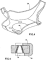
Figure 4 is a perspective view of the shell element of the wheel-carrying member ofFigure 1 ; -
Figure 5 is a section view of a portion of the wheel-carrying member ofFigure 1 , arranged for connection with a steering arm of the motor vehicle; -
Figure 6 is a perspective view of a metal insert of the wheel-carrying member ofFigure 1 , used for connecting an oscillating arm of the suspension to the wheel-carrying member; -
Figure 7 is a perspective view of a portion of the wheel-carrying member ofFigure 1 , where the metal insert ofFigure 6 is fixed; -
Figures 8 and 9 are perspective views from the external side and the internal side, respectively, of a wheel-carrying member according to a further embodiment of the present invention; -
Figure 10 is a section view of the wheel-carrying member ofFigures 8 and 9 , cut along section line X-X ofFigure 9 ; -
Figure 11 is a section view of the wheel-carrying member ofFigures 8 and 9 , cut along section line XI-XI ofFigure 9 ; -
Figure 12 is a section view of the wheel-carrying member ofFigures 8 and 9 , cut along section line XII-XII ofFigure 9 ; and -
Figure 13 is a section view of the wheel-carrying member ofFigures 8 and 9 , cut along section line XIII-XIII ofFigure 9 . - In the following description and claims, terms like "front" and "rear", "upper" and "lower", etc. are to be intended as referred to the mounted condition of the wheel-carrying member on a motor vehicle.
- With reference first to
Figure 1 , a wheel-carrying member according to an embodiment of the present invention is generally indicated with 10 and is used herein for supporting a front wheel of a motor vehicle in a McPherson suspension system. The use of the wheel-carrying member for a McPherson front suspension is, nevertheless, to be intended purely as a non-limitative example, as the wheel-carrying member according to the present invention can be used in any other type of suspension, be it a front suspension or a rear one. - With reference also to
Figures 2 and 3 , the wheel-carryingmember 10 has aseat 12 for the mounting of abearing 14 for supporting the wheel. The wheel-carryingmember 10 further comprises amounting portion 16 for the mounting of a shock absorber 18, amounting portion 20 for the mounting of abrake caliper 22, amounting portion 24 for the mounting of an oscillating arm (not shown) and amounting portion 26 for the mounting of a steering arm (not shown). - Of course, depending on the type of suspension the number and the arrangement of the mounting portions may change with respect to what is shown in the drawings. For example, in case of a rear suspension, where the wheel is usually a non-steering wheel, the wheel-carrying
member 10 would not include themounting portion 26. Furthermore, in case, for example, of a multi-link suspension, the wheel-carryingmember 10 will include a plurality of mounting portions for the mounting of the plurality of rods/arms of the suspension. - According to the invention, the wheel-carrying
member 10 has a hybrid structure comprising ashell element 28, abody 30 and a plurality of inserts (namely, a pair ofinserts 32 for fixing the wheel-carryingmember 10 to the shock absorber 18, a pair ofinserts 34 for fixing the wheel-carryingmember 10 to thebrake caliper 22, aninsert 36 for connecting the wheel-carryingmember 10 to the oscillating arm and aninsert 38 for connecting the wheel-carryingmember 10 to the steering arm). The shell element 28 (which is, in this case, a single shell element) is formed by a laminate with a thermoplastic matrix and is fixed to an external side of thebody 30. Thebody 30 is made of a composite material with a fibre-reinforced thermoplastic matrix and is shaped as a hollow body, with a cross section that is open towards the internal side (that is, towards the side that, in the mounted condition of the wheel-carrying member on a vehicle, faces towards the internal side of the vehicle). Theinserts - The
outer shell element 28 is advantageously made by thermoforming process. The overall geometry of the shell element, the features of each ply (woven or unidirectional fibres), the orientation of the carbon fibres and the type of reinforcement fibres (glass or carbon, long or short) will be selected based on the mechanical requirements for the wheel-carrying member. The type of thermoplastic resin will be selected based on the structural and environmental requirements for the wheel-carrying member. - According to an embodiment, for example, the
shell element 28 is made by stacking of pre-preg plies, reinforced with unidirectional carbon fibres, directed at 0/45/-45/90 degrees. The choice of the four directions indicated above allows for the highest degree of isotropy that can theoretically be obtained with a stacking of plies having unidirectional fibres. Theshell element 28 is balanced in the direction 45 degrees, so that a coupling effect between bending and torsion, which would occur in case of lack of balance, is avoided. - Nevertheless, the
shell element 28 may also be made, for example, by stacking of pre-preg plies with woven carbon fibres. - More generally, the
shell element 28 will be formed by a sequence of carbon-fibre (and, possibly, glass-fibre too) pre-preg plies, conveniently configured to maximise the mechanical performances of the component and bear the stresses the component undergoes in use. Furthermore, theshell element 28 may have a variable thickness, with a greater thickness in the areas where higher stresses are applied, or, alternatively, a constant thickness with localized reinforcements in the areas where higher stresses are applied. - The
shell element 28 may provide the wheel-carryingmember 10 with a greater level of stiffness than the one provided by thebody 30. The highest stiffness contribution by theshell element 28 is provided in the plane of the ply. However, by virtue of the particular geometry of theshell element 28 at the above-mentioned mounting portions, and more specifically by virtue of the presence of bent edges along some lengths of the perimeter of the shell element (see, for example,edge 40 inFigure 4 ), theshell element 28 provides a certain contribution to stiffness also outside the plane of the ply. - The
body 30 is made of a composite material with a thermoplastic matrix, for example with a polyphthalamide (PPA) or polyamide (PA6, PA66) matrix having mechanical characteristics that are selected based on the performance requirements for the wheel-carrying member. Because of the reduced water absorption tendency of the polyphthalamide, this material is particularly indicated for a component that is exposed, though not directly, to weather, as is the case for a wheel-carrying member. - Preferably, the same material used for the thermoplastic matrix of the
shell element 28 is also used for the thermoplastic matrix of thebody 30, so that compatibility issues between the shell element and the body during moulding are avoided. - The reinforcement fibres of the composite material of the
body 30 are, for example, glass fibres, in particular so-called "chopped" glass fibres. - The
body 30 provides the wheel-carryingmember 10 with a further amount of stiffness, in addition to the one provided by theshell element 28. In particular, thebody 30 provides a contribution to the stiffness outside the plane of the ply. - The
body 30 may be made by over-moulding of the composite material (for example polyphthalamide loaded with glass or carbon, long or short fibres) on theshell element 28 or in a same forming operation (the so-called "one shot" technique) or in a subsequent operation once the ply forming theshell element 28 has been obtained. - The
body 30 preferably has a plurality of ribs with a geometry and a thickness that are conveniently defined depending on the stress state to which the wheel-carrying member is subject in use. The ribs are made in a single piece with thebody 30 and are configured to adhere to theshell element 28 and to thebent edges 40 thereof, if any. - The
inserts body 30, preferably by insert moulding. In order to improve adhesion with the composite material of thebody 30, theinserts body 30, in order to improve the bonding of the joint between the inserts and the body. - With reference to
Figure 5 , theinsert 38 for connection of the wheel-carryingmember 10 to the steering arm is made, for example, as a conical insert, where the conical pin of a head 42 (shown inFigure 1 ) is intended to be inserted and secured with a nut, thehead 42 being coupled to the steering arm by a ball joint. The use of a conical insert, where the conical pin of the head is accommodated and locked, allows to distribute the steering loads, projecting the exchanged force not only on a radial direction, but also on an axial one. -
Figures 6 and 7 show in detail theinsert 36 used for connection of the wheel-carryingmember 10 to the oscillating arm. Theinsert 36 has aseat 44 for accommodating a cylindrical pin head (not shown) that is rigidly connected, for example by press-fitting, threaded connection or riveting, to the oscillating arm. - Preferably, the
insert 36 forms aprotrusion 46 and at least one undercut portion for increasing the contact surface between the metallic material of theinsert 36 and the composite material of thebody 30 and improving the bonding between the insert and the body (by virtue of the injected material of the body flowing into the undercut portion(s)). - With reference to
Figures 1 to 3 , the connection of the wheel-carryingmember 10 with theshock absorber 18 is obtained by screwing to the wheel-carrying member, in the region of theinserts 32, abracket 48 which is rigidly connected, for example by welding, to the body of the shock absorber. - The
inserts body 30 and at which the ribs of thebody 30 end. - A further embodiment of a wheel-carrying member according to the present invention is shown in
Figures 8 to 13 , where parts and elements identical or corresponding to the ones shown inFigures 1 to 7 are indicated with the same reference numbers. - According to this further embodiment, the wheel-carrying
member 10 comprises abody 30 and a number ofshell elements 28, which are separate from one another (in the present case, three shell elements indicated with 28', 28" and 28‴, respectively) and fixed to thebody 30 on the external side thereof, that is, on the side facing outwards of the vehicle in the mounted condition of the wheel-carryingmember 10 on the vehicle. - In the example shown in
Figures 8 to 13 , theshell elements 28', 28" and 28'" are positioned in the mountingportion 16 for the shock absorber, in the mountingportion 20 for the brake caliper, and in the mountingportion 26 for the steering arm, respectively. Of course, the number and the position of the shell elements may change depending on the specific requirements. - In addition, in this embodiment the
body 30 is made as a hollow body having across section that opens towards the internal side. In this case, therefore, thebent edges 40 described above with reference to the embodiment ofFigures 1 to 7 are formed by thebody 30, rather than by the shell element (or by one of the shell elements). - In order to make the structure of the wheel-carrying member more rigid, the
body 30 has a ribbed structure with a plurality of ribs 50 (that can be seen in particular inFigure 9 ) formed in a single piece with the body itself. - With reference to
Figures 10 to 12 , the metal inserts (inFigures 10 to 12 only the metal inserts 32, 34 and 36, along with a further metal insert 52 - shown in section inFigure 10 - that defines theseat 12 for the mounting of the wheel bearing, are shown in section) have each at least one undercutportion 54 filled by the injected material of thebody 30, which allows to improve the bonding between the inserts and the body and increase the overall strength and stiffness characteristics of the wheel-carrying member. - As regards the materials used for the body and the shell elements, as well as the manufacturing process of the wheel-carrying member, what has been explained above with reference to the embodiment of
Figures 1 to 7 still applies. - By virtue of the body and the shell element of the wheel-carrying member being made of a composite material and metallic material being only used for the inserts, the wheel-carrying member according to the present invention has a remarkably lower weight than a conventional wheel-carrying member entirely made of metal (such as steel, aluminium or cast iron), without thereby adversely affecting the performances of the wheel-carrying member. By means of a convenient design of the geometry and of the structure of the body and of the shell element it is, in fact, possible to provide a wheel-carrying member that is able to fulfil the requirements of the specific application for which the wheel-carrying member is designed.
- Naturally, the principle of the invention remaining unchanged, the embodiments and constructional details may vary widely from those described and illustrated purely by way of non-limiting example, without thereby departing from the scope of the invention as defined in the appended claims.
- In particular, as explained above, the overall geometry of the wheel-carrying member, the number, the arrangement and the configuration of the inserts, as well as the geometry and the internal structure of the shell element (or elements) and of the body, may change depending on the particular application for which the wheel-carrying member is designed.
Claims (12)
- Wheel-carrying member (10) for a vehicle suspension, with a hybrid structure comprising a body (30) in a composite material with a fibre-reinforced thermoplastic matrix , at least one shell element (28, 28', 28", 28"') formed by a laminate with a thermoplastic matrix and fixed on an external side of the body (30), which is a side of the body (30) that, in the mounted condition of the wheel-carrying member (10) on the vehicle, is directed laterally outwards of the vehicle,
and a plurality of metal inserts (32, 34, 36, 38, 52) for connecting or fixing the wheel-carrying member (10) to other components (18, 22) of the suspension or of the vehicle, said metal inserts (32, 34, 36, 38, 52) being at least partially embedded in the body (30) so that they are firmly connected to the body (30) without the use of adhesive means. - Wheel-carrying member according to claim 1, wherein the thermoplastic matrix of said at least one shell element (28, 28', 28", 28‴) and/or the thermoplastic matrix of the body (30) are made of polyphthalamide or polyamide.
- Wheel-carrying member according to claim 1 or claim 2, wherein the thermoplastic matrix of the internal body (30) is made of the same material as that of the thermoplastic matrix of said at least one shell element (28, 28', 28", 28‴).
- Wheel-carrying member according to any one of the preceding claims, wherein said metal inserts (32, 34, 36, 38, 52) include each at least one undercut portion (54) filled with the material of the body (30).
- Wheel-carrying member according to any one of the preceding claims, comprising a single shell element (28) that has bent edges (40) along at least one length of its perimeter.
- Wheel-carrying member according to any one of claims 1 to 4, wherein the body (30) is made as a hollow body having a cross section open towards the internal side.
- Wheel-carrying member according to claim 6, wherein the body (30) forms, along its perimeter, a plurality of bent edges (40).
- Wheel-carrying member according to any one of the preceding claims, wherein said plurality of metal inserts (32, 34, 36, 38, 52) comprises an insert (32) for fixing the wheel-carrying member (10) to a shock absorber (18) of the suspension, an insert (34) for fixing the wheel-carrying member (10) to a brake caliper (22), an insert (36) for connecting the wheel-carrying member (10) to an oscillating arm or other arm/rod of the suspension, an insert (52) that defines a seat (12) for the mounting of a wheel bearing (14) and/or an insert (38) for connecting the wheel-carrying member (10) to a steering arm.
- Wheel-carrying member according to any one of the preceding claims, wherein the body (30) has a ribbed structure.
- Vehicle suspension comprising a wheel-carrying member (10) according to any one of the preceding claims.
- Method for manufacturing a wheel-carrying member (10) for a vehicle suspension according to any one of claims from 1 to 9, comprising the steps of:a) providing said at least one shell element (28, 28', 28", 28"') by thermoforming;b) providing the body (30) by over-moulding of composite material on said at least one shell element (28, 28', 28", 28‴); andc) securing the metal inserts (32, 34, 36, 38, 54) to the body (30) by insert moulding.
- Method according to claim 11, wherein said steps a), b) and c) are performed in a same forming process or said steps b) and c) are performed after said step a).
Applications Claiming Priority (2)
| Application Number | Priority Date | Filing Date | Title |
|---|---|---|---|
| IT201700141159 | 2017-12-06 | ||
| PCT/IB2018/059712 WO2019111200A1 (en) | 2017-12-06 | 2018-12-06 | Wheel-carrying member for a vehicle suspension |
Publications (2)
| Publication Number | Publication Date |
|---|---|
| EP3720758A1 EP3720758A1 (en) | 2020-10-14 |
| EP3720758B1 true EP3720758B1 (en) | 2023-01-25 |
Family
ID=61656185
Family Applications (1)
| Application Number | Title | Priority Date | Filing Date |
|---|---|---|---|
| EP18827253.8A Active EP3720758B1 (en) | 2017-12-06 | 2018-12-06 | Wheel-carrying member for a vehicle suspension |
Country Status (4)
| Country | Link |
|---|---|
| EP (1) | EP3720758B1 (en) |
| CN (1) | CN111417566B (en) |
| BR (1) | BR112020011491B1 (en) |
| WO (1) | WO2019111200A1 (en) |
Families Citing this family (1)
| Publication number | Priority date | Publication date | Assignee | Title |
|---|---|---|---|---|
| IT201800007980A1 (en) | 2018-08-08 | 2020-02-08 | Skf Ab | LOW WEIGHT SUSPENSION POST OR JOINT |
Family Cites Families (8)
| Publication number | Priority date | Publication date | Assignee | Title |
|---|---|---|---|---|
| DE102007053120B4 (en) * | 2007-11-08 | 2021-06-24 | Bayerische Motoren Werke Aktiengesellschaft | Vehicle wheel carriers, in particular steering knuckles or swivel bearings, made from a fiber composite material, and manufacturing processes therefor |
| DE102013209987B3 (en) * | 2013-05-29 | 2014-11-13 | Technische Universität Dresden | Wheel carrier assembly for a motor vehicle |
| US10202148B2 (en) * | 2013-06-07 | 2019-02-12 | Aktiebolaget Skf | Lightweight steering knuckle |
| CN203581095U (en) * | 2013-12-03 | 2014-05-07 | 上海通用汽车有限公司 | Connection assembly of aluminum knuckle and lining |
| KR101549915B1 (en) * | 2013-12-04 | 2015-09-04 | 주식회사 일진 | Knuckle of vehicle and manufacturing method thereof |
| CN105818858A (en) * | 2015-08-19 | 2016-08-03 | 瑞安市联众汽车零部件有限公司 | Steering knuckle for vehicle |
| JP6402861B2 (en) * | 2016-01-21 | 2018-10-10 | トヨタ自動車株式会社 | Vehicle suspension members |
| US10473147B2 (en) * | 2016-03-15 | 2019-11-12 | Federal-Mogul Motorparts Llc | Socket assembly and method of making a socket assembly |
-
2018
- 2018-12-06 WO PCT/IB2018/059712 patent/WO2019111200A1/en not_active Ceased
- 2018-12-06 EP EP18827253.8A patent/EP3720758B1/en active Active
- 2018-12-06 CN CN201880077349.1A patent/CN111417566B/en active Active
- 2018-12-06 BR BR112020011491-0A patent/BR112020011491B1/en active IP Right Grant
Also Published As
| Publication number | Publication date |
|---|---|
| EP3720758A1 (en) | 2020-10-14 |
| CN111417566B (en) | 2023-12-15 |
| BR112020011491A2 (en) | 2020-11-17 |
| CN111417566A (en) | 2020-07-14 |
| BR112020011491B1 (en) | 2024-02-27 |
| WO2019111200A1 (en) | 2019-06-13 |
Similar Documents
| Publication | Publication Date | Title |
|---|---|---|
| US9487058B2 (en) | Composite structural element, particularly for a vehicle suspension, and method for manufacturing the same | |
| CN103261003B (en) | Motor vehicle body with reinforcing braces | |
| CN107000523B (en) | Chassis and method for manufacturing a chassis | |
| US11014610B2 (en) | Chassis component for a motor vehicle, and method for producing a chassis component | |
| JP6186426B2 (en) | shock absorber | |
| US20100084834A1 (en) | Connector piece for the articulated connection of components located in the suspension of a vehicle | |
| CN110154662A (en) | Connecting rod for wheel suspension | |
| US20170008359A1 (en) | Motor vehicle wheel suspension | |
| CN102844205B (en) | There is the wheel suspension of crossed strip sheet | |
| CN107635856B (en) | Metal cross members with composite fiber subframes | |
| EP3720758B1 (en) | Wheel-carrying member for a vehicle suspension | |
| US11351836B2 (en) | Stabilizer bar for a chassis of a motor vehicle, and method for producing such a stabilizer bar | |
| EP3456557B1 (en) | Oscillating arm of a motor-vehicle suspension | |
| WO2017135806A1 (en) | Vehicle monocoque body and method of manufacturing thereof | |
| CN108688730B (en) | Connection structure for connecting a fiber-reinforced plastic part to a connecting part and corresponding assembly | |
| US11186131B2 (en) | Lightweight suspension upright assembly for a vehicle | |
| EP3661773B1 (en) | Method for manufacturing a composite twist-beam axle for a rear suspension of a vehicle | |
| US20220297490A1 (en) | Trailing arm attachment portion structure | |
| EP4210974A1 (en) | A method for manufacturing a suspension arm for an automotive suspension and suspension arm obtained by said method | |
| US20220297360A1 (en) | Trailing arm manufacturing method | |
| CN107458161A (en) | Dimeric wheel suspension unit | |
| CN102844583B (en) | Articulated composite spring leaf for the ground contact system of a motor vehicle, method of manufacture thereof and ground contact system created |
Legal Events
| Date | Code | Title | Description |
|---|---|---|---|
| STAA | Information on the status of an ep patent application or granted ep patent |
Free format text: STATUS: UNKNOWN |
|
| STAA | Information on the status of an ep patent application or granted ep patent |
Free format text: STATUS: THE INTERNATIONAL PUBLICATION HAS BEEN MADE |
|
| PUAI | Public reference made under article 153(3) epc to a published international application that has entered the european phase |
Free format text: ORIGINAL CODE: 0009012 |
|
| STAA | Information on the status of an ep patent application or granted ep patent |
Free format text: STATUS: REQUEST FOR EXAMINATION WAS MADE |
|
| 17P | Request for examination filed |
Effective date: 20200615 |
|
| AK | Designated contracting states |
Kind code of ref document: A1 Designated state(s): AL AT BE BG CH CY CZ DE DK EE ES FI FR GB GR HR HU IE IS IT LI LT LU LV MC MK MT NL NO PL PT RO RS SE SI SK SM TR |
|
| AX | Request for extension of the european patent |
Extension state: BA ME |
|
| RIN1 | Information on inventor provided before grant (corrected) |
Inventor name: PULINA, FABIO Inventor name: SANTINI, ANDREA Inventor name: SOTTILE, SALVATORE |
|
| DAV | Request for validation of the european patent (deleted) | ||
| DAX | Request for extension of the european patent (deleted) | ||
| STAA | Information on the status of an ep patent application or granted ep patent |
Free format text: STATUS: EXAMINATION IS IN PROGRESS |
|
| 17Q | First examination report despatched |
Effective date: 20211004 |
|
| GRAP | Despatch of communication of intention to grant a patent |
Free format text: ORIGINAL CODE: EPIDOSNIGR1 |
|
| STAA | Information on the status of an ep patent application or granted ep patent |
Free format text: STATUS: GRANT OF PATENT IS INTENDED |
|
| INTG | Intention to grant announced |
Effective date: 20220729 |
|
| GRAS | Grant fee paid |
Free format text: ORIGINAL CODE: EPIDOSNIGR3 |
|
| GRAA | (expected) grant |
Free format text: ORIGINAL CODE: 0009210 |
|
| STAA | Information on the status of an ep patent application or granted ep patent |
Free format text: STATUS: THE PATENT HAS BEEN GRANTED |
|
| AK | Designated contracting states |
Kind code of ref document: B1 Designated state(s): AL AT BE BG CH CY CZ DE DK EE ES FI FR GB GR HR HU IE IS IT LI LT LU LV MC MK MT NL NO PL PT RO RS SE SI SK SM TR |
|
| REG | Reference to a national code |
Ref country code: GB Ref legal event code: FG4D |
|
| REG | Reference to a national code |
Ref country code: CH Ref legal event code: EP |
|
| REG | Reference to a national code |
Ref country code: AT Ref legal event code: REF Ref document number: 1545729 Country of ref document: AT Kind code of ref document: T Effective date: 20230215 Ref country code: IE Ref legal event code: FG4D |
|
| REG | Reference to a national code |
Ref country code: DE Ref legal event code: R096 Ref document number: 602018045808 Country of ref document: DE |
|
| REG | Reference to a national code |
Ref country code: LT Ref legal event code: MG9D |
|
| REG | Reference to a national code |
Ref country code: NL Ref legal event code: MP Effective date: 20230125 |
|
| REG | Reference to a national code |
Ref country code: AT Ref legal event code: MK05 Ref document number: 1545729 Country of ref document: AT Kind code of ref document: T Effective date: 20230125 |
|
| PG25 | Lapsed in a contracting state [announced via postgrant information from national office to epo] |
Ref country code: NL Free format text: LAPSE BECAUSE OF FAILURE TO SUBMIT A TRANSLATION OF THE DESCRIPTION OR TO PAY THE FEE WITHIN THE PRESCRIBED TIME-LIMIT Effective date: 20230125 |
|
| PG25 | Lapsed in a contracting state [announced via postgrant information from national office to epo] |
Ref country code: RS Free format text: LAPSE BECAUSE OF FAILURE TO SUBMIT A TRANSLATION OF THE DESCRIPTION OR TO PAY THE FEE WITHIN THE PRESCRIBED TIME-LIMIT Effective date: 20230125 Ref country code: PT Free format text: LAPSE BECAUSE OF FAILURE TO SUBMIT A TRANSLATION OF THE DESCRIPTION OR TO PAY THE FEE WITHIN THE PRESCRIBED TIME-LIMIT Effective date: 20230525 Ref country code: NO Free format text: LAPSE BECAUSE OF FAILURE TO SUBMIT A TRANSLATION OF THE DESCRIPTION OR TO PAY THE FEE WITHIN THE PRESCRIBED TIME-LIMIT Effective date: 20230425 Ref country code: LV Free format text: LAPSE BECAUSE OF FAILURE TO SUBMIT A TRANSLATION OF THE DESCRIPTION OR TO PAY THE FEE WITHIN THE PRESCRIBED TIME-LIMIT Effective date: 20230125 Ref country code: LT Free format text: LAPSE BECAUSE OF FAILURE TO SUBMIT A TRANSLATION OF THE DESCRIPTION OR TO PAY THE FEE WITHIN THE PRESCRIBED TIME-LIMIT Effective date: 20230125 Ref country code: HR Free format text: LAPSE BECAUSE OF FAILURE TO SUBMIT A TRANSLATION OF THE DESCRIPTION OR TO PAY THE FEE WITHIN THE PRESCRIBED TIME-LIMIT Effective date: 20230125 Ref country code: ES Free format text: LAPSE BECAUSE OF FAILURE TO SUBMIT A TRANSLATION OF THE DESCRIPTION OR TO PAY THE FEE WITHIN THE PRESCRIBED TIME-LIMIT Effective date: 20230125 Ref country code: AT Free format text: LAPSE BECAUSE OF FAILURE TO SUBMIT A TRANSLATION OF THE DESCRIPTION OR TO PAY THE FEE WITHIN THE PRESCRIBED TIME-LIMIT Effective date: 20230125 |
|
| PG25 | Lapsed in a contracting state [announced via postgrant information from national office to epo] |
Ref country code: SE Free format text: LAPSE BECAUSE OF FAILURE TO SUBMIT A TRANSLATION OF THE DESCRIPTION OR TO PAY THE FEE WITHIN THE PRESCRIBED TIME-LIMIT Effective date: 20230125 Ref country code: PL Free format text: LAPSE BECAUSE OF FAILURE TO SUBMIT A TRANSLATION OF THE DESCRIPTION OR TO PAY THE FEE WITHIN THE PRESCRIBED TIME-LIMIT Effective date: 20230125 Ref country code: IS Free format text: LAPSE BECAUSE OF FAILURE TO SUBMIT A TRANSLATION OF THE DESCRIPTION OR TO PAY THE FEE WITHIN THE PRESCRIBED TIME-LIMIT Effective date: 20230525 Ref country code: GR Free format text: LAPSE BECAUSE OF FAILURE TO SUBMIT A TRANSLATION OF THE DESCRIPTION OR TO PAY THE FEE WITHIN THE PRESCRIBED TIME-LIMIT Effective date: 20230426 Ref country code: FI Free format text: LAPSE BECAUSE OF FAILURE TO SUBMIT A TRANSLATION OF THE DESCRIPTION OR TO PAY THE FEE WITHIN THE PRESCRIBED TIME-LIMIT Effective date: 20230125 |
|
| REG | Reference to a national code |
Ref country code: DE Ref legal event code: R097 Ref document number: 602018045808 Country of ref document: DE |
|
| PG25 | Lapsed in a contracting state [announced via postgrant information from national office to epo] |
Ref country code: SM Free format text: LAPSE BECAUSE OF FAILURE TO SUBMIT A TRANSLATION OF THE DESCRIPTION OR TO PAY THE FEE WITHIN THE PRESCRIBED TIME-LIMIT Effective date: 20230125 Ref country code: RO Free format text: LAPSE BECAUSE OF FAILURE TO SUBMIT A TRANSLATION OF THE DESCRIPTION OR TO PAY THE FEE WITHIN THE PRESCRIBED TIME-LIMIT Effective date: 20230125 Ref country code: EE Free format text: LAPSE BECAUSE OF FAILURE TO SUBMIT A TRANSLATION OF THE DESCRIPTION OR TO PAY THE FEE WITHIN THE PRESCRIBED TIME-LIMIT Effective date: 20230125 Ref country code: DK Free format text: LAPSE BECAUSE OF FAILURE TO SUBMIT A TRANSLATION OF THE DESCRIPTION OR TO PAY THE FEE WITHIN THE PRESCRIBED TIME-LIMIT Effective date: 20230125 Ref country code: CZ Free format text: LAPSE BECAUSE OF FAILURE TO SUBMIT A TRANSLATION OF THE DESCRIPTION OR TO PAY THE FEE WITHIN THE PRESCRIBED TIME-LIMIT Effective date: 20230125 |
|
| PG25 | Lapsed in a contracting state [announced via postgrant information from national office to epo] |
Ref country code: SK Free format text: LAPSE BECAUSE OF FAILURE TO SUBMIT A TRANSLATION OF THE DESCRIPTION OR TO PAY THE FEE WITHIN THE PRESCRIBED TIME-LIMIT Effective date: 20230125 |
|
| PLBE | No opposition filed within time limit |
Free format text: ORIGINAL CODE: 0009261 |
|
| STAA | Information on the status of an ep patent application or granted ep patent |
Free format text: STATUS: NO OPPOSITION FILED WITHIN TIME LIMIT |
|
| 26N | No opposition filed |
Effective date: 20231026 |
|
| PG25 | Lapsed in a contracting state [announced via postgrant information from national office to epo] |
Ref country code: SI Free format text: LAPSE BECAUSE OF FAILURE TO SUBMIT A TRANSLATION OF THE DESCRIPTION OR TO PAY THE FEE WITHIN THE PRESCRIBED TIME-LIMIT Effective date: 20230125 |
|
| REG | Reference to a national code |
Ref country code: CH Ref legal event code: PL |
|
| PG25 | Lapsed in a contracting state [announced via postgrant information from national office to epo] |
Ref country code: LU Free format text: LAPSE BECAUSE OF NON-PAYMENT OF DUE FEES Effective date: 20231206 |
|
| PG25 | Lapsed in a contracting state [announced via postgrant information from national office to epo] |
Ref country code: MC Free format text: LAPSE BECAUSE OF FAILURE TO SUBMIT A TRANSLATION OF THE DESCRIPTION OR TO PAY THE FEE WITHIN THE PRESCRIBED TIME-LIMIT Effective date: 20230125 |
|
| GBPC | Gb: european patent ceased through non-payment of renewal fee |
Effective date: 20231206 |
|
| REG | Reference to a national code |
Ref country code: BE Ref legal event code: MM Effective date: 20231231 |
|
| PG25 | Lapsed in a contracting state [announced via postgrant information from national office to epo] |
Ref country code: MC Free format text: LAPSE BECAUSE OF FAILURE TO SUBMIT A TRANSLATION OF THE DESCRIPTION OR TO PAY THE FEE WITHIN THE PRESCRIBED TIME-LIMIT Effective date: 20230125 Ref country code: LU Free format text: LAPSE BECAUSE OF NON-PAYMENT OF DUE FEES Effective date: 20231206 |
|
| REG | Reference to a national code |
Ref country code: IE Ref legal event code: MM4A |
|
| PG25 | Lapsed in a contracting state [announced via postgrant information from national office to epo] |
Ref country code: IE Free format text: LAPSE BECAUSE OF NON-PAYMENT OF DUE FEES Effective date: 20231206 |
|
| PG25 | Lapsed in a contracting state [announced via postgrant information from national office to epo] |
Ref country code: GB Free format text: LAPSE BECAUSE OF NON-PAYMENT OF DUE FEES Effective date: 20231206 |
|
| PG25 | Lapsed in a contracting state [announced via postgrant information from national office to epo] |
Ref country code: BE Free format text: LAPSE BECAUSE OF NON-PAYMENT OF DUE FEES Effective date: 20231231 |
|
| PG25 | Lapsed in a contracting state [announced via postgrant information from national office to epo] |
Ref country code: CH Free format text: LAPSE BECAUSE OF NON-PAYMENT OF DUE FEES Effective date: 20231231 |
|
| PG25 | Lapsed in a contracting state [announced via postgrant information from national office to epo] |
Ref country code: IE Free format text: LAPSE BECAUSE OF NON-PAYMENT OF DUE FEES Effective date: 20231206 Ref country code: GB Free format text: LAPSE BECAUSE OF NON-PAYMENT OF DUE FEES Effective date: 20231206 Ref country code: CH Free format text: LAPSE BECAUSE OF NON-PAYMENT OF DUE FEES Effective date: 20231231 Ref country code: BE Free format text: LAPSE BECAUSE OF NON-PAYMENT OF DUE FEES Effective date: 20231231 |
|
| PG25 | Lapsed in a contracting state [announced via postgrant information from national office to epo] |
Ref country code: BG Free format text: LAPSE BECAUSE OF FAILURE TO SUBMIT A TRANSLATION OF THE DESCRIPTION OR TO PAY THE FEE WITHIN THE PRESCRIBED TIME-LIMIT Effective date: 20230125 |
|
| PG25 | Lapsed in a contracting state [announced via postgrant information from national office to epo] |
Ref country code: BG Free format text: LAPSE BECAUSE OF FAILURE TO SUBMIT A TRANSLATION OF THE DESCRIPTION OR TO PAY THE FEE WITHIN THE PRESCRIBED TIME-LIMIT Effective date: 20230125 |
|
| PG25 | Lapsed in a contracting state [announced via postgrant information from national office to epo] |
Ref country code: CY Free format text: LAPSE BECAUSE OF FAILURE TO SUBMIT A TRANSLATION OF THE DESCRIPTION OR TO PAY THE FEE WITHIN THE PRESCRIBED TIME-LIMIT; INVALID AB INITIO Effective date: 20181206 |
|
| PG25 | Lapsed in a contracting state [announced via postgrant information from national office to epo] |
Ref country code: HU Free format text: LAPSE BECAUSE OF FAILURE TO SUBMIT A TRANSLATION OF THE DESCRIPTION OR TO PAY THE FEE WITHIN THE PRESCRIBED TIME-LIMIT; INVALID AB INITIO Effective date: 20181206 |
|
| PG25 | Lapsed in a contracting state [announced via postgrant information from national office to epo] |
Ref country code: TR Free format text: LAPSE BECAUSE OF FAILURE TO SUBMIT A TRANSLATION OF THE DESCRIPTION OR TO PAY THE FEE WITHIN THE PRESCRIBED TIME-LIMIT Effective date: 20230125 |
|
| PGFP | Annual fee paid to national office [announced via postgrant information from national office to epo] |
Ref country code: DE Payment date: 20251126 Year of fee payment: 8 |
|
| PGFP | Annual fee paid to national office [announced via postgrant information from national office to epo] |
Ref country code: IT Payment date: 20251119 Year of fee payment: 8 |
|
| PGFP | Annual fee paid to national office [announced via postgrant information from national office to epo] |
Ref country code: FR Payment date: 20251119 Year of fee payment: 8 |