EP3720677B1 - Method for remolding thermoplastic trays - Google Patents
Method for remolding thermoplastic trays Download PDFInfo
- Publication number
- EP3720677B1 EP3720677B1 EP18815637.6A EP18815637A EP3720677B1 EP 3720677 B1 EP3720677 B1 EP 3720677B1 EP 18815637 A EP18815637 A EP 18815637A EP 3720677 B1 EP3720677 B1 EP 3720677B1
- Authority
- EP
- European Patent Office
- Prior art keywords
- indicator
- injection molding
- thermoplastic
- trays
- degrading
- Prior art date
- Legal status (The legal status is an assumption and is not a legal conclusion. Google has not performed a legal analysis and makes no representation as to the accuracy of the status listed.)
- Active
Links
Images

Classifications
-
- B—PERFORMING OPERATIONS; TRANSPORTING
- B29—WORKING OF PLASTICS; WORKING OF SUBSTANCES IN A PLASTIC STATE IN GENERAL
- B29C—SHAPING OR JOINING OF PLASTICS; SHAPING OF MATERIAL IN A PLASTIC STATE, NOT OTHERWISE PROVIDED FOR; AFTER-TREATMENT OF THE SHAPED PRODUCTS, e.g. REPAIRING
- B29C45/00—Injection moulding, i.e. forcing the required volume of moulding material through a nozzle into a closed mould; Apparatus therefor
- B29C45/17—Component parts, details or accessories; Auxiliary operations
- B29C45/26—Moulds
- B29C45/37—Mould cavity walls, i.e. the inner surface forming the mould cavity, e.g. linings
- B29C45/372—Mould cavity walls, i.e. the inner surface forming the mould cavity, e.g. linings provided with means for marking or patterning, e.g. numbering articles
-
- B—PERFORMING OPERATIONS; TRANSPORTING
- B29—WORKING OF PLASTICS; WORKING OF SUBSTANCES IN A PLASTIC STATE IN GENERAL
- B29B—PREPARATION OR PRETREATMENT OF THE MATERIAL TO BE SHAPED; MAKING GRANULES OR PREFORMS; RECOVERY OF PLASTICS OR OTHER CONSTITUENTS OF WASTE MATERIAL CONTAINING PLASTICS
- B29B17/00—Recovery of plastics or other constituents of waste material containing plastics
- B29B17/0026—Recovery of plastics or other constituents of waste material containing plastics by agglomeration or compacting
- B29B17/0042—Recovery of plastics or other constituents of waste material containing plastics by agglomeration or compacting for shaping parts, e.g. multilayered parts with at least one layer containing regenerated plastic
-
- B—PERFORMING OPERATIONS; TRANSPORTING
- B29—WORKING OF PLASTICS; WORKING OF SUBSTANCES IN A PLASTIC STATE IN GENERAL
- B29B—PREPARATION OR PRETREATMENT OF THE MATERIAL TO BE SHAPED; MAKING GRANULES OR PREFORMS; RECOVERY OF PLASTICS OR OTHER CONSTITUENTS OF WASTE MATERIAL CONTAINING PLASTICS
- B29B17/00—Recovery of plastics or other constituents of waste material containing plastics
- B29B17/04—Disintegrating plastics, e.g. by milling
- B29B17/0404—Disintegrating plastics, e.g. by milling to powder
-
- B—PERFORMING OPERATIONS; TRANSPORTING
- B29—WORKING OF PLASTICS; WORKING OF SUBSTANCES IN A PLASTIC STATE IN GENERAL
- B29B—PREPARATION OR PRETREATMENT OF THE MATERIAL TO BE SHAPED; MAKING GRANULES OR PREFORMS; RECOVERY OF PLASTICS OR OTHER CONSTITUENTS OF WASTE MATERIAL CONTAINING PLASTICS
- B29B17/00—Recovery of plastics or other constituents of waste material containing plastics
- B29B17/04—Disintegrating plastics, e.g. by milling
- B29B2017/0424—Specific disintegrating techniques; devices therefor
- B29B2017/0484—Grinding tools, roller mills or disc mills
-
- B—PERFORMING OPERATIONS; TRANSPORTING
- B29—WORKING OF PLASTICS; WORKING OF SUBSTANCES IN A PLASTIC STATE IN GENERAL
- B29C—SHAPING OR JOINING OF PLASTICS; SHAPING OF MATERIAL IN A PLASTIC STATE, NOT OTHERWISE PROVIDED FOR; AFTER-TREATMENT OF THE SHAPED PRODUCTS, e.g. REPAIRING
- B29C37/00—Component parts, details, accessories or auxiliary operations, not covered by group B29C33/00 or B29C35/00
- B29C2037/80—Identifying, e.g. coding, dating, marking, numbering
-
- B—PERFORMING OPERATIONS; TRANSPORTING
- B29—WORKING OF PLASTICS; WORKING OF SUBSTANCES IN A PLASTIC STATE IN GENERAL
- B29K—INDEXING SCHEME ASSOCIATED WITH SUBCLASSES B29B, B29C OR B29D, RELATING TO MOULDING MATERIALS OR TO MATERIALS FOR MOULDS, REINFORCEMENTS, FILLERS OR PREFORMED PARTS, e.g. INSERTS
- B29K2105/00—Condition, form or state of moulded material or of the material to be shaped
- B29K2105/26—Scrap or recycled material
-
- Y—GENERAL TAGGING OF NEW TECHNOLOGICAL DEVELOPMENTS; GENERAL TAGGING OF CROSS-SECTIONAL TECHNOLOGIES SPANNING OVER SEVERAL SECTIONS OF THE IPC; TECHNICAL SUBJECTS COVERED BY FORMER USPC CROSS-REFERENCE ART COLLECTIONS [XRACs] AND DIGESTS
- Y02—TECHNOLOGIES OR APPLICATIONS FOR MITIGATION OR ADAPTATION AGAINST CLIMATE CHANGE
- Y02W—CLIMATE CHANGE MITIGATION TECHNOLOGIES RELATED TO WASTEWATER TREATMENT OR WASTE MANAGEMENT
- Y02W30/00—Technologies for solid waste management
- Y02W30/50—Reuse, recycling or recovery technologies
- Y02W30/62—Plastics recycling; Rubber recycling
Definitions
- the present invention relates to remolding and recycling processes, and in particular to a method for remolding thermoplastic materials in connection with production and use of carriers consisting of such materials.
- thermoplastics are polymers that become pliable or moldable above a specific temperature and solidify upon cooling.
- thermoplastics may - as opposed to thermoset plastics - be reshaped by heating.
- thermoplastics are many, which spires from the materials being adaptable in terms of shape and properties to specific applications in combination with favorable properties in terms of durability and an associated low cost of production.
- thermoplastics are however associated with a number of down sides; one being that the economic incentives for reusing thermoplastics are insufficient. Also, recycling thermoplastics to produce high-grade products is associated with technical difficulties. Consequently, due to the industry's incentives for responsible utilization of virgin material into quality products being sparse, more sustainable examples of where thermoplastics are reused to produce new quality products are today still few.
- waste material is typically either collected and combusted for heat generation or used as low grade bulk material i.a. within construction.
- thermoplastics are typically not subjected to refinement of waste material necessary to be able to anew produce high grade products.
- DE2211882 discloses the processing steps a-d of claim 1 in suit after exact separation of plastic waste.
- thermoplastic material comprising the steps of: molding thermoplastic carriers in an injection molding apparatus; using the molded carriers in a transportation and/or manufacturing process; degrading the used carriers in a degrading apparatus to obtain a non-virgin granulate; and providing the non-virgin granulate to the injection molding apparatus for recycling.
- the injection molding apparatus is configured to - in the molding step - mold the thermoplastic carriers with an integrally formed indicator which is indicative of the injection molding apparatus.
- the thermoplastic carriers Prior to the degrading, are selectively filtered by means of the associated indicators so that correctly indicated, used carriers are fed into the degrading apparatus. Used carriers are selectively filtered by means of the indicator being detected by means of a filtering device.
- the indicator is provided with information which is specific to the injection molding apparatus, whereby the origin of the indicator is made traceable.
- the indicator is provided with information relating to injection molding properties of a thermoplastic material; thus facilitating obtaining high grade items when remolding the material.
- the indicator is provided with information relating to material preferences of the injection molding apparatus. Thereby relevant information is given regarding which injection molding apparatus the material is suitable for.
- the indicator is provided with visually intelligible information; thereby facilitating ease of identification e.g. to an operator.
- the indicator is provided with information comprising a modulus of elasticity and/or a melt index; thereby providing information relevant for remolding of the material.
- the indicator comprises a light absorption coefficient.
- the carrier is provided with a detectable characterization facilitating ease of filtering the carrier.
- the indicator is molded in a mold cavity of the injection molding apparatus, whereby the indicator is formed as an integral part of the carrier and thus being less susceptible to mechanical and chemical wear while providing a cost and time efficient manufacturing process.
- thermoplastic carriers are molded in an injection molding apparatus 401 as shown in Fig. 3 .
- the injection molding apparatus 401 is basically of a known design and is not described in detail here.
- aspects comprise thermoplastic carriers in the form of trays 305 which can carry for instance items to be used in manufacturing or assembly processes.
- Each thermoplastic tray 305 is molded with an indicator 330 which can be a kind of marking on a side surface of the tray 305 (see Fig. 3A ).
- the thermoplastic material is polypropylene (PP) but other thermoplastic materials are feasible.
- the trays 305 are - in a subsequent step 105 - selectively filtered by means of the indicator 330, and in a further subsequent step 106 the trays 305 are degraded to obtain a non-virgin granulate 333.
- the non-virgin granulate 333 is provided to the injection molding apparatus 401 for recycling the thermoplastic material e.g. by feeding the non-virgin granulate to the injection molding apparatus 401 as material for molding trays 305.
- Fig. 2 illustrates a further embodiment.
- an injection molding apparatus 401 is provided with a virgin thermoplastic material 332 (see Fig. 3 ).
- thermoplastic trays 305 are molded in the injection molding apparatus 401.
- the thermoplastic trays 305 are molded with an indicator 330.
- the trays 305 are assembled - here stacked - to a form a tray assembly 306 (see Fig. 3 ).
- This stack 306 of trays 305 may be transported to a user or a manufacturing process 402, for instance a car manufacturing plant in a still further step 104, wherein the tray assembly 306 is disassembled - for instance at said plant.
- the trays 305 are selectively filtered by means of the associated indicator 330 identified for instance by a filtering device 403 which can be either automatic or staff-operated, such as by an operator supervising a degrading mill ( Fig 3 ).
- a filtering device 403 which can be either automatic or staff-operated, such as by an operator supervising a degrading mill ( Fig 3 ).
- the trays 305 are degraded to obtain a non-virgin granulate 333 which may have a particle size of approximately 1-2 mm.
- the degrading is performed in a degrading apparatus 404 which can be of known design not described in detail here. For instance, it can be a milling unit.
- a step of mechanical cleaning 405 of the non-virgin granulate may follow the degrading step 106.
- the non-virgin granulate 333 is brought to the injection molding apparatus 401 for recycling the thermoplastic material, typically in the form of pelletized granulate.
- the non-virgin granulate 333 may be blended to comprise 3 to 7 % virgin thermoplastic material 332, preferably 4 to 6 %, more preferably 5 %.
- a high-grade material may be referred to as a pure material in the meaning that it has a composition substantially corresponding to or purely corresponding to that of the virgin material composition selected.
- the selected material may in turn comprise one or more components i.e. a mix of compounds to achieve the desired properties of the material used for the injection molding.
- thermoplastic material used as input material to the injection molding apparatus 401 in the remolding cycle 100, 200.
- each tray 305 is indicative of the injection molding apparatus 401 in which it has been molded.
- the trays 305 may comprise one indicator or a plurality of indicators.
- the indicator(s) 330 are(is) disposed on one or more external surfaces of the trays 305, for example on a side surface, on a top face or a bottom face of the trays 305 for increased exposure and thus facilitating ease of identification.
- the indicator 330 may comprise information relating to the geographic location of the injection molding apparatus 401 in which the trays 305 having the indicator 330 were molded. Furthermore, the indicator 330 may carry information relating to injection molding properties of the thermoplastic material 332, 333 used for the trays 305.
- the indicator 330 includes information relating to injection molding properties of the material of the trays 305 i.a. injection molding properties may include injection molding parameters and/or modulus of elasticity and melt index of the material.
- the indicator 330 may carry information relating to injection molding properties of a thermoplastic material which corresponds to material preferences of the injection molding apparatus 401.
- the injection moulding apparatus 401 is configured to provide the thermoplastic trays 305 with an indicator 330 by means of a mold cavity of the injection molding apparatus 401.
- the mold cavity per se constitutes the mold forming the indicator 330.
- the injection molding apparatus 401 is configured to follow a number of commands corresponding to an injection molding sequence to produce the trays 305 such that the injection molding apparatus 401 carries out the commands.
- the injection molding apparatus 401 may be provided with a digital model (not shown), such as a discretized 3D model of the tray 305 and/or the mold cavity for producing the tray 305.
- the trays 305 are selectively filtered by various filtering means or devices 403 as will be explained herein.
- the indicator 330 comprises a detectable indicator 330 unique for the present material used to manufacture the trays 305. As such, the indicator 330 may take various forms and may be detected and distinguished by means of various detection means used to filter the trays 305.
- the indicator 330 may comprise a visual indicator which includes visually readily derivable information, e.g. text intelligible to an operator or sensor means.
- the indicator 330 comprises a melt index representing the amount of a thermoplastic resin, measured in grams, which can be forced through a specified orifice within a time interval when subjected to a specified force.
- the indicator 330 comprises a brand or product name in combination with a melt index and/or an E-modulus of the thermoplastic material of the tray 305.
- An example "RECOPAC ® XX-YYY” is shown in Fig. 3A , where RECOPAC ® is a registered trademark owned by the Swedish company Molander Tech AB belonging to the same Group as the present applicant.
- the identification XX represents the melt index and YYY the E-modulus of the thermoplastic material used for the tray 305 in question.
- the indicator 305 may be detectable by means of Optical Character Recognition or the like image or text recognition means (not shown).
- the indicator 330 may comprise a unique shape, such as a 3D barcode (not shown).
- the indicator 330 may be provided with a tactile indicator comprising protrusions or depressions (not shown).
- the indicator 330 may include a resonance indicator, for example the indicator or the material of the tray may absorb and/reflect soundwaves having a specific frequency (not shown).
- the indicator 330 may comprise a molecular label, for example the thermoplastic material may have a certain composition detectable by means of a detection means, such as a chemical detection means e.g a remote near infrared sensor, absorption spectrum, extinction coefficient, remote spectral sensing or the like (not shown).
- a detection means such as a chemical detection means e.g a remote near infrared sensor, absorption spectrum, extinction coefficient, remote spectral sensing or the like (not shown).
- the indicator 330 may include surface roughness indicator, detectable by means of surface analysis means or an operator (not shown).
- the indicator 330 may comprise a surface indicator detectable by means of light scattering (not shown).
- the indicator 330 may also have a mechanically stamped indicator (not shown).
- the indicator 330 may comprise a light absorbance coefficient indicator (not shown), and in certain embodiments the indicator 330 is based on the provision that the tray 305 has a light absorbance coefficient different from a light absorbance coefficient of a pallet 308 and/or a cover 307 and/or other components of a tray stack or assembly 306.
- the indicator 330 may be based on the provision that the tray 305 having a light absorbance coefficient being higher than a light absorbance coefficient of the pallet 308 and/or the cover 307 and/or other components of the tray assembly 306.
- the trays 305 serve to carry goods 309, such as products for delivery to a manufacturing process.
- the tray 305 or a plurality of trays 305 may constitute a packaging.
- the method 100, 200 may further comprise the step of stacking one or more trays 305 interposed between the pallet 308 and the cover 307.
- the trays 305 are assembled, for example stacked, to form a shipment-ready tray stack or assembly 306 which may be compatible e.g. with means such as a fork-lift.
- the tray assembly 306 may comprise the stackable trays 305 stacked on each other on the customized pallet 308 underneath the trays 305 and supplied with a customized lid or cover 307 above the trays 305.
- the tray assembly 306 is utilized for transportation purposes involving one or more thermoplastic trays 305 for accommodating goods 309.
- the entities contributing to the structural integrity of the tray assembly 306 may include, not limited to the pallet 308, the tray(s) 305, the cover 307 and the goods 309 to be transported and/or used in the manufacturing process.
- the method 100, 200 may comprise a sending step, where the injection molding apparatus 401 provides the tray 305 with a modulation in the form of an indicator 330 and the method 100, 200 comprises a receiving step comprising filtering material to pass material comprising the modulation in the form of the indicator 330 (not shown).
- the receiving step comprises recognition of the indicator 330 and a step of filtering to pass only trays bearing the indicator 330.
- the tray assembly 306 is disassembled and the components of the tray assembly 306, i.e. one or more trays 305, the pallet 308, the cover 307, are collected at one or more recycle facilities for mechanically degrading the thermoplastic trays 305 by means of one or more degradation apparatus 404 in a degradation step to obtain a non-virgin thermoplastic granulate 333.
- the recycle facility upon implementation of the disclosed method 100, 200 and system 300, comprises one or more facilities at various geographic locations.
- the recycle facility may comprise selective filtering apparatus 403 as well as degradation apparatus 404 for mechanically degrading the trays 305.
- the method 100, 200 comprises the step of selectively filtering the thermoplastic tray 305 from pallet 308 and lid 307.
- thermoplastic trays 305 are selectively filtered by means of the indicator 330 so that correctly indicated trays 305 are fed into the degrading apparatus 404.
- the degrading apparatus 404 may comprise one or more milling units (not shown).
- the step of selectively filtering comprises selectively selecting one or more of the components of the tray assembly 306 by means of the indicator 330 and corresponding methods for detecting the indicator 330 as described herein.
- the step of selectively filtering 106 may be carried out by a filtering device 403 which automatically or semi-automatically detects the indicator 330.
- the method 100, 200 comprises a step 106 of degrading the thermoplastic trays 305 in the degrading apparatus 404 to obtain a non-virgin granulate 333, and providing the non-virgin granulate 333 to the injection molding apparatus 401 for recycling.
- the degrading apparatus 404 comprises one or more milling units at various geographical locations (not shown). Furthermore, the degrading apparatus 404 includes means for mechanically degrading the trays 305 such as to reduce the volume of the thermoplastic trays 305, i.e. increase the density. The degrading apparatus 404 includes means for grounding flakes into a non-virgin granulate 333.
- the recycle facilities may as mentioned comprise one or more facilities at various geographic locations. For example, an advantage is achieved if the non-virgin material 333 is shipped as flakes or as granulate in order to reduce the volume of the material, thereby being more cost-efficient to transport.
- the one or more degrading steps 106 facilitate(s) obtaining a granulate 333 for use in the injection molding apparatus 401.
- thermoplastic granulate 333 may contain debris of other materials present in the handling and logistic chain of the present system 300. This may for instance take place between a user, such as a manufacturing process 402, and a facility carrying out the filtering step 105 and the degrading apparatus 404, such as metal or plastics, thermoplastic material of different grade having material properties different from that of what is required by the injection molding apparatus 401, or otherwise not compatible with the injection molding apparatus 401 or would not result in trays 305 having the required properties.
- a step of mechanical cleaning of the granulate may be necessary to safeguard the preferred pureness of the non-virgin material 333 prescribed by the injection molding apparatus 401 and/or as prescribed in order to achieve the preferred mechanical properties of the trays 305.
- Mechanical cleaning may be performed by means of a process or mechanical cleaning apparatus 405.
- the step of mechanical cleaning of the granulate 333 which forms part of the disclosed method may be reduced or rendered obsolete by carrying out the disclosed method 100, 200.
- the system comprises one or more of: an injection molding apparatus 401 for molding thermoplastic trays 305, a manufacturing process facility 402, a filtering device 403, a degrading apparatus 404 for degrading the thermoplastic trays 305 to obtain a non-virgin granulate 333, a mechanical cleaning apparatus 405.
- the injection molding apparatus 401 is configured to mold the thermoplastic trays 305 with an integrally formed indicator 330, indicator indicative of the injection molding apparatus 401. Prior to the degrading, the thermoplastic trays 305 are selectively filtered 105 by means of the indicator 330 so that correctly indicated trays are fed into the degrading apparatus 404.
- the method comprises a step of providing thermoplastic carriers or trays 305 configured to be used in a transportation and/or manufacturing process.
- the carriers 305 which are injection moulded, are provided with a sign or markings 330 related to the thermoplastic material.
- the used carriers 305 are degraded to obtain granulate.
- the thermoplastic carriers 305 Prior to the degrading station 404, are selectively filtered by means of the associated signs/markings 330 so that correctly indicated, used carriers 305 are fed to the degrading station 404 whereas carriers with incorrect signs/markings are rejected.
- correctly identified thermoplastic material is degraded in the station 404.
- the subsequent line after the degrading station 404 may include a cleaning station 405 and thereafter an injection molding station 401 in which fresh trays 305 are produced.
- the disclosed method has several advantages not limited to reduced cost of the entire cycle 100, 200 of remolding the thermoplastic material, reduced mechanical cleaning, improved quality of the thermoplastic trays 305, less down-time in production and thereby improved economy and shortened lead-time and improved reliability of the trays 305.
- thermoplastics materials become pliable or moldable above a specific temperature and solidify upon cooling.
- Injection molding is a manufacturing process for producing articles by injecting material into a mold.
- the injection molding process can be performed with a host of materials mainly including metals, glasses, elastomers, confections, and most commonly thermoplastic and thermosetting polymers.
- Material for the article is fed into a heated barrel, mixed, and forced into a mold cavity, where it cools and hardens to the configuration of the cavity.
- molds are made typically from metal, usually either steel or aluminum, and precision-machined to form the features of the desired article.
- Injection molding is widely used for manufacturing a variety of articles, from the smallest components to entire body panels of cars. Advances in 3D printing technology, using photopolymers which do not melt during the injection molding of some lower temperature thermoplastics, can be used for some simple injection molds.
- Articles to be injection molded must are carefully designed to facilitate the molding process.
- the material used for the article, the desired shape and features of the article, the material of the mold, and the properties of the molding machine must all be taken into account.
- the versatility of injection molding is facilitated by this breadth of design considerations and possibilities.
- the material which is typically supplied in the form of pelletized thermoplastic material should preferably comprise an elastic modulus within the specific range dictated during the design process.
- the recycled material can contain fractions of other materials or impurities resulting in a new diluted material composition, thereby rendering a recycled material with different characteristics than the initial virgin material used at the outset, which for various reasons may be undesired for the injection molding apparatus or the finished injection molded item.
- Impurities in the material can for example include deviating mean particle size, altered injection molding characteristics or alien objects causing harm to the injection molding equipment.
- the injection molding apparatus may not be compatible with the new material composition, the components of the injection molding apparatus such as injectors or the mold cavity typically require a certain particle size, such as a maximum particle size, or a certain E-modulus, certain melting properties, viscosity at a given temperature or curing properties.
- a certain particle size such as a maximum particle size, or a certain E-modulus, certain melting properties, viscosity at a given temperature or curing properties.
- Injection molded articles may be highly customized to the intended use, for example to a specific product, to minimize material consumption and to minimize weight of the article.
Landscapes
- Engineering & Computer Science (AREA)
- Mechanical Engineering (AREA)
- Environmental & Geological Engineering (AREA)
- Manufacturing & Machinery (AREA)
- Injection Moulding Of Plastics Or The Like (AREA)
Description
- The present invention relates to remolding and recycling processes, and in particular to a method for remolding thermoplastic materials in connection with production and use of carriers consisting of such materials.
- Thermoplastics are polymers that become pliable or moldable above a specific temperature and solidify upon cooling. Thus, thermoplastics may - as opposed to thermoset plastics - be reshaped by heating.
- The industrial applications of thermoplastics are many, which spires from the materials being adaptable in terms of shape and properties to specific applications in combination with favorable properties in terms of durability and an associated low cost of production.
- Comparatively low production costs of thermoplastics are however associated with a number of down sides; one being that the economic incentives for reusing thermoplastics are insufficient. Also, recycling thermoplastics to produce high-grade products is associated with technical difficulties. Consequently, due to the industry's incentives for responsible utilization of virgin material into quality products being sparse, more sustainable examples of where thermoplastics are reused to produce new quality products are today still few.
- However, as environmental aspects climb the agenda worldwide, steps have been taken towards more sustainable utilization of natural resources in general and materials are being recycled to a greater extent. In the field of plastics, however, waste material is typically either collected and combusted for heat generation or used as low grade bulk material i.a. within construction. Thus, thermoplastics are typically not subjected to refinement of waste material necessary to be able to anew produce high grade products.
- In this regard, certain systems and methods are known for instance from
WO2017/007913A1 ,DE2211882A1 andDE3934969A1 . However, these known systems suffer from most of the disadvantages as discussed above. - More specifically,
DE2211882 discloses the processing steps a-d of claim 1 in suit after exact separation of plastic waste. - As such, there is a need for an improved material utilization in connection with remolding and recycling of articles made of thermoplastics; in particular trays for carrying goods.
- It is thus an object of the present invention to provide an improved technique for recycling thermoplastics in order to overcome or at least mitigate the disadvantages of prior-art methods and systems. This object has now been achieved by a method set forth in appended claim 1; preferred embodiments being defined in claims 2-9.
- In an aspect, there is provided a method for remolding a thermoplastic material comprising the steps of: molding thermoplastic carriers in an injection molding apparatus; using the molded carriers in a transportation and/or manufacturing process; degrading the used carriers in a degrading apparatus to obtain a non-virgin granulate; and providing the non-virgin granulate to the injection molding apparatus for recycling. The injection molding apparatus is configured to - in the molding step - mold the thermoplastic carriers with an integrally formed indicator which is indicative of the injection molding apparatus. Prior to the degrading, the thermoplastic carriers are selectively filtered by means of the associated indicators so that correctly indicated, used carriers are fed into the degrading apparatus. Used carriers are selectively filtered by means of the indicator being detected by means of a filtering device. Hereby improved quality of the material is achieved. Further advantages will be explained herein.
- In a feasible implementation, the indicator is provided with information which is specific to the injection molding apparatus, whereby the origin of the indicator is made traceable.
- In a further possible implementation, the indicator is provided with information relating to injection molding properties of a thermoplastic material; thus facilitating obtaining high grade items when remolding the material.
- In yet another feasible implementation, the indicator is provided with information relating to material preferences of the injection molding apparatus. Thereby relevant information is given regarding which injection molding apparatus the material is suitable for.
- In a possible implementation, the indicator is provided with visually intelligible information; thereby facilitating ease of identification e.g. to an operator.
- In a further feasible implementation, the indicator is provided with information comprising a modulus of elasticity and/or a melt index; thereby providing information relevant for remolding of the material.
- In another possible implementation, the indicator comprises a light absorption coefficient. Thereby the carrier is provided with a detectable characterization facilitating ease of filtering the carrier.
- In still another possible implementation, the indicator is molded in a mold cavity of the injection molding apparatus, whereby the indicator is formed as an integral part of the carrier and thus being less susceptible to mechanical and chemical wear while providing a cost and time efficient manufacturing process.
- Further advantages of the above aspect and implementations will be described in the following.
- Embodiments of the present invention will now be described with reference to the accompanying drawings which illustrate non-limiting examples on how the embodiments can be reduced into practice and in which:
-
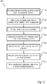
Fig. 1 is a diagrammatic representation of a method according to one embodiment of the disclosure, -
Fig. 2 is a diagrammatic representation of a method according to a further embodiment of the disclosure, -
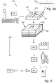
Fig. 3 shows a system for remolding a thermoplastics material according an embodiment, and -
Fig. 3A shows a detail ofFig.3 on a larger scale. - In
Fig. 1 there is illustrated an exemplary method of remolding a thermoplastic material according to one embodiment. Instep 102, thermoplastic carriers are molded in aninjection molding apparatus 401 as shown inFig. 3 . Theinjection molding apparatus 401 is basically of a known design and is not described in detail here. - Generally in this disclosure, aspects comprise thermoplastic carriers in the form of
trays 305 which can carry for instance items to be used in manufacturing or assembly processes. Eachthermoplastic tray 305 is molded with anindicator 330 which can be a kind of marking on a side surface of the tray 305 (seeFig. 3A ). Preferably, the thermoplastic material is polypropylene (PP) but other thermoplastic materials are feasible. - After use in a transportation and/or manufacturing process 104 (not described in detail here), the
trays 305 are - in a subsequent step 105 - selectively filtered by means of theindicator 330, and in a furthersubsequent step 106 thetrays 305 are degraded to obtain anon-virgin granulate 333. In afinal step 107, thenon-virgin granulate 333 is provided to theinjection molding apparatus 401 for recycling the thermoplastic material e.g. by feeding the non-virgin granulate to theinjection molding apparatus 401 as material formolding trays 305. -
Fig. 2 illustrates a further embodiment. In a first step 101, aninjection molding apparatus 401 is provided with a virgin thermoplastic material 332 (seeFig. 3 ). In asubsequent step 102,thermoplastic trays 305 are molded in theinjection molding apparatus 401. Thethermoplastic trays 305 are molded with anindicator 330. In a yetfurther step 103, thetrays 305 are assembled - here stacked - to a form a tray assembly 306 (seeFig. 3 ). Thisstack 306 oftrays 305 may be transported to a user or amanufacturing process 402, for instance a car manufacturing plant in a stillfurther step 104, wherein thetray assembly 306 is disassembled - for instance at said plant. - In
step 105, thetrays 305 are selectively filtered by means of the associatedindicator 330 identified for instance by afiltering device 403 which can be either automatic or staff-operated, such as by an operator supervising a degrading mill (Fig 3 ). In one or more followingdegrading steps 106, thetrays 305 are degraded to obtain anon-virgin granulate 333 which may have a particle size of approximately 1-2 mm. The degrading is performed in adegrading apparatus 404 which can be of known design not described in detail here. For instance, it can be a milling unit. - A step of
mechanical cleaning 405 of the non-virgin granulate may follow thedegrading step 106. Finally, thenon-virgin granulate 333 is brought to theinjection molding apparatus 401 for recycling the thermoplastic material, typically in the form of pelletized granulate. Thenon-virgin granulate 333 may be blended to comprise 3 to 7 % virginthermoplastic material 332, preferably 4 to 6 %, more preferably 5 %. - In order to obtain refined high-grade articles through an injection molding process, the choice of material may be imperative. A number of material-related characteristics may be taken into account, such as the composition and the pureness of the input material to the process. A high-grade material may be referred to as a pure material in the meaning that it has a composition substantially corresponding to or purely corresponding to that of the virgin material composition selected. The selected material may in turn comprise one or more components i.e. a mix of compounds to achieve the desired properties of the material used for the injection molding.
- Accordingly, in the process of remolding a thermoplastic material there may be demands on the thermoplastic material used as input material to the
injection molding apparatus 401 in theremolding cycle - It is an object of the present disclosure to control the material flow in a cycle for remolding thermoplastic material in order to safeguard quality and reliability of the molded product, to reduce down-time in manufacturing and to reduce or render obsolete any mechanical cleaning necessary to obtain a high-grade
non-virgin material 333 for theremolding cycle remolding cycle - As will be explained herein, objects of the disclosure are achieved by providing a
method indicator 330 of eachtray 305 is indicative of theinjection molding apparatus 401 in which it has been molded. - The
trays 305 may comprise one indicator or a plurality of indicators. The indicator(s) 330 are(is) disposed on one or more external surfaces of thetrays 305, for example on a side surface, on a top face or a bottom face of thetrays 305 for increased exposure and thus facilitating ease of identification. - The
indicator 330 may comprise information relating to the geographic location of theinjection molding apparatus 401 in which thetrays 305 having theindicator 330 were molded. Furthermore, theindicator 330 may carry information relating to injection molding properties of thethermoplastic material trays 305. - In certain embodiments, the
indicator 330 includes information relating to injection molding properties of the material of thetrays 305 i.a. injection molding properties may include injection molding parameters and/or modulus of elasticity and melt index of the material. Theindicator 330 may carry information relating to injection molding properties of a thermoplastic material which corresponds to material preferences of theinjection molding apparatus 401. - The
injection moulding apparatus 401 is configured to provide thethermoplastic trays 305 with anindicator 330 by means of a mold cavity of theinjection molding apparatus 401. Thus, the mold cavity per se constitutes the mold forming theindicator 330. Also, theinjection molding apparatus 401 is configured to follow a number of commands corresponding to an injection molding sequence to produce thetrays 305 such that theinjection molding apparatus 401 carries out the commands. Further, theinjection molding apparatus 401 may be provided with a digital model (not shown), such as a discretized 3D model of thetray 305 and/or the mold cavity for producing thetray 305. - The
trays 305 are selectively filtered by various filtering means ordevices 403 as will be explained herein. Theindicator 330 comprises adetectable indicator 330 unique for the present material used to manufacture thetrays 305. As such, theindicator 330 may take various forms and may be detected and distinguished by means of various detection means used to filter thetrays 305. - The
indicator 330 may comprise a visual indicator which includes visually readily derivable information, e.g. text intelligible to an operator or sensor means. In particular, theindicator 330 comprises a melt index representing the amount of a thermoplastic resin, measured in grams, which can be forced through a specified orifice within a time interval when subjected to a specified force. - In a preferred embodiment, the
indicator 330 comprises a brand or product name in combination with a melt index and/or an E-modulus of the thermoplastic material of thetray 305. An example "RECOPAC® XX-YYY" is shown inFig. 3A , where RECOPAC® is a registered trademark owned by the Swedish company Molander Tech AB belonging to the same Group as the present applicant. The identification XX represents the melt index and YYY the E-modulus of the thermoplastic material used for thetray 305 in question. - In the recognition and filtering step, only correctly identified
trays 305 carrying the RECOPAC® sign are passed further to the degradingmill 404. Trays identified as incorrect - that is trays without the RECOPAC® sign - are rejected from the flow/line by thefiltering device 403. Thereby, only correctly identifiedtrays 305 having the RECOPAC® sign are fed into themill 404. Hereby, it is secured that "clean" thermoplastic material is degraded in themill 404 and passed further to next step in the recycling loop (seeFig. 3 ). - Other examples of identification comprise melt-flow rate, melt-flow index, or base resin melt index. The
indicator 305 may be detectable by means of Optical Character Recognition or the like image or text recognition means (not shown). In certain embodiments, theindicator 330 may comprise a unique shape, such as a 3D barcode (not shown). - Furthermore, the
indicator 330 may be provided with a tactile indicator comprising protrusions or depressions (not shown). Theindicator 330 may include a resonance indicator, for example the indicator or the material of the tray may absorb and/reflect soundwaves having a specific frequency (not shown). - In addition, the
indicator 330 may comprise a molecular label, for example the thermoplastic material may have a certain composition detectable by means of a detection means, such as a chemical detection means e.g a remote near infrared sensor, absorption spectrum, extinction coefficient, remote spectral sensing or the like (not shown). Furthermore, theindicator 330 may include surface roughness indicator, detectable by means of surface analysis means or an operator (not shown). In certain cases, theindicator 330 may comprise a surface indicator detectable by means of light scattering (not shown). Theindicator 330 may also have a mechanically stamped indicator (not shown). - The
indicator 330 may comprise a light absorbance coefficient indicator (not shown), and in certain embodiments theindicator 330 is based on the provision that thetray 305 has a light absorbance coefficient different from a light absorbance coefficient of apallet 308 and/or acover 307 and/or other components of a tray stack orassembly 306. - The
indicator 330 may be based on the provision that thetray 305 having a light absorbance coefficient being higher than a light absorbance coefficient of thepallet 308 and/or thecover 307 and/or other components of thetray assembly 306. - The
trays 305 serve to carrygoods 309, such as products for delivery to a manufacturing process. In this sense, thetray 305 or a plurality oftrays 305 may constitute a packaging. Themethod more trays 305 interposed between thepallet 308 and thecover 307. - In certain applications, the
trays 305 are assembled, for example stacked, to form a shipment-ready tray stack orassembly 306 which may be compatible e.g. with means such as a fork-lift. Thetray assembly 306 may comprise thestackable trays 305 stacked on each other on the customizedpallet 308 underneath thetrays 305 and supplied with a customized lid or cover 307 above thetrays 305. As shown, thetray assembly 306 is utilized for transportation purposes involving one or morethermoplastic trays 305 for accommodatinggoods 309. The entities contributing to the structural integrity of thetray assembly 306 may include, not limited to thepallet 308, the tray(s) 305, thecover 307 and thegoods 309 to be transported and/or used in the manufacturing process. - The
method injection molding apparatus 401 provides thetray 305 with a modulation in the form of anindicator 330 and themethod indicator 330 and a step of filtering to pass only trays bearing theindicator 330. - In a
system 300 for carrying out themethod tray assembly 306 is disassembled and the components of thetray assembly 306, i.e. one ormore trays 305, thepallet 308, thecover 307, are collected at one or more recycle facilities for mechanically degrading thethermoplastic trays 305 by means of one ormore degradation apparatus 404 in a degradation step to obtain a non-virginthermoplastic granulate 333. The recycle facility, upon implementation of the disclosedmethod system 300, comprises one or more facilities at various geographic locations. The recycle facility may compriseselective filtering apparatus 403 as well asdegradation apparatus 404 for mechanically degrading thetrays 305. Thus, themethod thermoplastic tray 305 frompallet 308 andlid 307. - According to the
method trays 305, thethermoplastic trays 305 are selectively filtered by means of theindicator 330 so that correctly indicatedtrays 305 are fed into thedegrading apparatus 404. Thedegrading apparatus 404 may comprise one or more milling units (not shown). - The step of selectively filtering comprises selectively selecting one or more of the components of the
tray assembly 306 by means of theindicator 330 and corresponding methods for detecting theindicator 330 as described herein. The step of selectively filtering 106 may be carried out by afiltering device 403 which automatically or semi-automatically detects theindicator 330. - The
method step 106 of degrading thethermoplastic trays 305 in thedegrading apparatus 404 to obtain anon-virgin granulate 333, and providing thenon-virgin granulate 333 to theinjection molding apparatus 401 for recycling. - The
degrading apparatus 404 comprises one or more milling units at various geographical locations (not shown). Furthermore, thedegrading apparatus 404 includes means for mechanically degrading thetrays 305 such as to reduce the volume of thethermoplastic trays 305, i.e. increase the density. Thedegrading apparatus 404 includes means for grounding flakes into anon-virgin granulate 333. The recycle facilities may as mentioned comprise one or more facilities at various geographic locations. For example, an advantage is achieved if thenon-virgin material 333 is shipped as flakes or as granulate in order to reduce the volume of the material, thereby being more cost-efficient to transport. - The one or more
degrading steps 106 facilitate(s) obtaining agranulate 333 for use in theinjection molding apparatus 401. - However, further steps of mechanical cleaning of the
thermoplastic granulate 333 e.g. by means of amechanical cleaning apparatus 404, may be necessary as the granulate 333 may contain debris of other materials present in the handling and logistic chain of thepresent system 300. This may for instance take place between a user, such as amanufacturing process 402, and a facility carrying out thefiltering step 105 and thedegrading apparatus 404, such as metal or plastics, thermoplastic material of different grade having material properties different from that of what is required by theinjection molding apparatus 401, or otherwise not compatible with theinjection molding apparatus 401 or would not result intrays 305 having the required properties. - Consequently, a step of mechanical cleaning of the granulate may be necessary to safeguard the preferred pureness of the
non-virgin material 333 prescribed by theinjection molding apparatus 401 and/or as prescribed in order to achieve the preferred mechanical properties of thetrays 305. Mechanical cleaning may be performed by means of a process ormechanical cleaning apparatus 405. - The step of mechanical cleaning of the granulate 333 which forms part of the disclosed method may be reduced or rendered obsolete by carrying out the disclosed
method - The system comprises one or more of: an
injection molding apparatus 401 for moldingthermoplastic trays 305, amanufacturing process facility 402, afiltering device 403, adegrading apparatus 404 for degrading thethermoplastic trays 305 to obtain anon-virgin granulate 333, amechanical cleaning apparatus 405. Theinjection molding apparatus 401 is configured to mold thethermoplastic trays 305 with an integrally formedindicator 330, indicator indicative of theinjection molding apparatus 401. Prior to the degrading, thethermoplastic trays 305 are selectively filtered 105 by means of theindicator 330 so that correctly indicated trays are fed into thedegrading apparatus 404. - In an aspect, the method comprises a step of providing thermoplastic carriers or
trays 305 configured to be used in a transportation and/or manufacturing process. Thecarriers 305, which are injection moulded, are provided with a sign ormarkings 330 related to the thermoplastic material. In a degradingstation 404, the usedcarriers 305 are degraded to obtain granulate. Prior to the degradingstation 404, thethermoplastic carriers 305 are selectively filtered by means of the associated signs/markings 330 so that correctly indicated, usedcarriers 305 are fed to the degradingstation 404 whereas carriers with incorrect signs/markings are rejected. Hence, correctly identified thermoplastic material is degraded in thestation 404. Hereby improved quality of the thermoplastic material is achieved in the recycling loop. The subsequent line after the degradingstation 404 may include a cleaningstation 405 and thereafter aninjection molding station 401 in whichfresh trays 305 are produced. - The disclosed method has several advantages not limited to reduced cost of the
entire cycle thermoplastic trays 305, less down-time in production and thereby improved economy and shortened lead-time and improved reliability of thetrays 305. - As stated above thermoplastics materials become pliable or moldable above a specific temperature and solidify upon cooling.
- Injection molding is a manufacturing process for producing articles by injecting material into a mold. The injection molding process can be performed with a host of materials mainly including metals, glasses, elastomers, confections, and most commonly thermoplastic and thermosetting polymers. Material for the article is fed into a heated barrel, mixed, and forced into a mold cavity, where it cools and hardens to the configuration of the cavity. After a product is designed, molds are made typically from metal, usually either steel or aluminum, and precision-machined to form the features of the desired article. Injection molding is widely used for manufacturing a variety of articles, from the smallest components to entire body panels of cars. Advances in 3D printing technology, using photopolymers which do not melt during the injection molding of some lower temperature thermoplastics, can be used for some simple injection molds.
- Articles to be injection molded must are carefully designed to facilitate the molding process. The material used for the article, the desired shape and features of the article, the material of the mold, and the properties of the molding machine must all be taken into account. The versatility of injection molding is facilitated by this breadth of design considerations and possibilities.
- The material, which is typically supplied in the form of pelletized thermoplastic material should preferably comprise an elastic modulus within the specific range dictated during the design process.
- As a selected material is recycled, the recycled material can contain fractions of other materials or impurities resulting in a new diluted material composition, thereby rendering a recycled material with different characteristics than the initial virgin material used at the outset, which for various reasons may be undesired for the injection molding apparatus or the finished injection molded item. Impurities in the material can for example include deviating mean particle size, altered injection molding characteristics or alien objects causing harm to the injection molding equipment.
- For example, the injection molding apparatus may not be compatible with the new material composition, the components of the injection molding apparatus such as injectors or the mold cavity typically require a certain particle size, such as a maximum particle size, or a certain E-modulus, certain melting properties, viscosity at a given temperature or curing properties.
- Consequently, neglecting to provide the injection molding apparatus with the prescribed material potentially have severe consequences in production, cause damage and defects to the molded product or system shutdown of the injection molding apparatus. In addition, such variances in the material provided to the injection molding apparatus can further result in the molded article not being provided with the prescribed properties as calculated during the design phase. The molded article may not have the structural integrity demanded for its use and may as a consequence fail during such use.
- Injection molded articles may be highly customized to the intended use, for example to a specific product, to minimize material consumption and to minimize weight of the article.
- In order to do so without jeopardizing the function of the article, care must be taken during the design phase. Since the design phase relies on the quality of the material prescribed, it is suitable to supply the manufacturing process with a material exhibiting essentially the prescribed properties.
- As shown herein, sustainability is not necessarily associated with higher costs. Rather, the described embodiments show that advantages of a sustainable production of high grade products are not limited to environmental aspects, but that with such interplay synergistic effects arise also in terms inter alia of quality and economy.
- Finally it should be mentioned that the inventive concept is by no means limited to the embodiments and examples described here, and modifications are feasible within the scope of invention set forth in the appended claims. For instance, the specific appearance of the carriers or trays may vary depending on the purpose of the same - in particular the products to be carried and transported. Furthermore, the specific type of thermoplastic material to be remolded can vary.
Claims (9)
- A method for remolding thermoplastic material, said method comprising the steps of:a) molding thermoplastic carriers in an injection molding apparatus;b) using the molded carriers in a transportation and/or manufacturing process;c) degrading the used carriers in a degrading apparatus to obtain a non-virgin granulate; andd) providing said non-virgin granulate to said injection molding apparatus for recycling;e) wherein said injection moulding apparatus - in said molding step - is configured to mold each thermoplastic carrier with an integrally formed indicator which is indicative of said injection molding apparatus;f) wherein - prior to said degrading step - the thermoplastic carriers are selectively filtered by means of the associated indicators, so that correctly indicated, used carriers are fed into said degrading apparatus; andg) wherein used carriers are selectively filtered by means of said indicator being detected by means of a filtering device.
- The method according to claim 1, wherein used thermoplastic carriers identified as incorrect by said filtering device - prior to the degrading step - are rejected from the recycling loop.
- The method according to claim 1 or 2, wherein said indicator is provided with information which is specific to said injection molding apparatus.
- The method according to any one of claims 1 to 3, wherein said indicator is provided with information relating to injection molding properties of a thermoplastic material.
- The method according to any one of claims 1 to 4, wherein said indicator is provided with information relating to material preferences of said injection molding apparatus.
- The method according to any one of claims 1 to 5, wherein said indicator is provided with visually intelligible information.
- The method according to any one of claims 1 to 6, wherein said indicator is provided with information comprising a modulus of elasticity and/or a melt index.
- The method according to any one of claims 1 to 7, wherein said indicator comprises a light absorption coefficient.
- The method according to any one of claims 1 to 8, wherein said indicator is molded in a mold cavity of said injection molding apparatus .
Applications Claiming Priority (2)
| Application Number | Priority Date | Filing Date | Title |
|---|---|---|---|
| SE1751503 | 2017-12-06 | ||
| PCT/EP2018/083680 WO2019110677A1 (en) | 2017-12-06 | 2018-12-05 | Method and system for remolding thermoplastic trays |
Publications (2)
| Publication Number | Publication Date |
|---|---|
| EP3720677A1 EP3720677A1 (en) | 2020-10-14 |
| EP3720677B1 true EP3720677B1 (en) | 2022-09-14 |
Family
ID=64661359
Family Applications (1)
| Application Number | Title | Priority Date | Filing Date |
|---|---|---|---|
| EP18815637.6A Active EP3720677B1 (en) | 2017-12-06 | 2018-12-05 | Method for remolding thermoplastic trays |
Country Status (2)
| Country | Link |
|---|---|
| EP (1) | EP3720677B1 (en) |
| WO (1) | WO2019110677A1 (en) |
Family Cites Families (4)
| Publication number | Priority date | Publication date | Assignee | Title |
|---|---|---|---|---|
| DE221882C (en) | ||||
| DE2211882A1 (en) * | 1972-03-11 | 1973-09-20 | Max Schmidt | Disposal of plastic waste containers - by reprocessing |
| DE3934969A1 (en) * | 1989-08-26 | 1991-02-28 | Karl Dipl Ing Schmitt | Producing and recycling mass produced plastics prods. - by marking according to chemical compsn. to allow sorting and reprocessing after use |
| CA2991318C (en) | 2015-07-08 | 2025-09-09 | Divert, Inc. | System for tracking waste or recyclable material |
-
2018
- 2018-12-05 EP EP18815637.6A patent/EP3720677B1/en active Active
- 2018-12-05 WO PCT/EP2018/083680 patent/WO2019110677A1/en not_active Ceased
Also Published As
| Publication number | Publication date |
|---|---|
| WO2019110677A1 (en) | 2019-06-13 |
| EP3720677A1 (en) | 2020-10-14 |
Similar Documents
| Publication | Publication Date | Title |
|---|---|---|
| Garmulewicz et al. | Disruptive technology as an enabler of the circular economy: what potential does 3D printing hold? | |
| US7534378B2 (en) | Plastic forming process monitoring and control | |
| AU2016274212B2 (en) | Tip-proof feeding bowl for house pets | |
| CA3082151C (en) | Converting recyclable materials into manufacturing products | |
| US20080265461A1 (en) | Method and Apparatus for Blow-Molding Containers with In-Mold Film Having RFID Tag Fused Thereto | |
| Muccio | Plastics processing technology | |
| DE50311760D1 (en) | CONTAINER FOR PACKAGING PRODUCTS, PLASTIC PROCESSING DEVICE AND METHOD FOR PRODUCING TANKS | |
| US20080150701A1 (en) | Method and apparatus for forming plastics with integral RFID devices | |
| WO2019110677A1 (en) | Method and system for remolding thermoplastic trays | |
| US20080179336A1 (en) | Method and article for deterring theft of returnable containers | |
| Olmsted et al. | Practical injection molding | |
| Michaeli et al. | Training in injection molding: a text-and workbook | |
| Brandau | Bottles, preforms and closures: a design guide for PET packaging | |
| WO2013176701A1 (en) | Method for operating a high productivity injection molding machine | |
| Uluskan | Six Sigma in Plastic Injection Molding: Reuse Defective Parts in New Article Production As Raw Material Input or Not? | |
| EP4183553A4 (en) | METHOD FOR MANAGING INFORMATION ON RESIN MOLDED PRODUCTS, METHOD FOR MANUFACTURING A RESIN CONTAINER, APPARATUS FOR MANAGING INFORMATION ON RESIN MOLDED PRODUCTS, AND BLOW MOLDING APPARATUS | |
| EP4434715A1 (en) | Method for realizing embossed decorative elements on physical supports | |
| Salminen | Using recycled polyethylene terephthalate (PET) in the production of bottle trays | |
| CN112988745A (en) | Feeding bar code scanning management system | |
| Dvorak | Applicability of recycled HDPE for rotational molding | |
| CN105328863A (en) | High-precision automated assembly and packaging system for injection products | |
| CN109228117A (en) | A kind of automatic injection machine | |
| KR102719947B1 (en) | Plastic card manufacturing system with automatic sorting function | |
| Fabe | Viability of Postconsumer Thermoplastics in Consumer Grade Additive Manufacturing | |
| US20100314044A1 (en) | Apparatus & method for making an air filter |
Legal Events
| Date | Code | Title | Description |
|---|---|---|---|
| STAA | Information on the status of an ep patent application or granted ep patent |
Free format text: STATUS: UNKNOWN |
|
| STAA | Information on the status of an ep patent application or granted ep patent |
Free format text: STATUS: THE INTERNATIONAL PUBLICATION HAS BEEN MADE |
|
| PUAI | Public reference made under article 153(3) epc to a published international application that has entered the european phase |
Free format text: ORIGINAL CODE: 0009012 |
|
| STAA | Information on the status of an ep patent application or granted ep patent |
Free format text: STATUS: REQUEST FOR EXAMINATION WAS MADE |
|
| 17P | Request for examination filed |
Effective date: 20200703 |
|
| AK | Designated contracting states |
Kind code of ref document: A1 Designated state(s): AL AT BE BG CH CY CZ DE DK EE ES FI FR GB GR HR HU IE IS IT LI LT LU LV MC MK MT NL NO PL PT RO RS SE SI SK SM TR |
|
| AX | Request for extension of the european patent |
Extension state: BA ME |
|
| DAV | Request for validation of the european patent (deleted) | ||
| DAX | Request for extension of the european patent (deleted) | ||
| STAA | Information on the status of an ep patent application or granted ep patent |
Free format text: STATUS: EXAMINATION IS IN PROGRESS |
|
| 17Q | First examination report despatched |
Effective date: 20210809 |
|
| GRAP | Despatch of communication of intention to grant a patent |
Free format text: ORIGINAL CODE: EPIDOSNIGR1 |
|
| STAA | Information on the status of an ep patent application or granted ep patent |
Free format text: STATUS: GRANT OF PATENT IS INTENDED |
|
| INTG | Intention to grant announced |
Effective date: 20220422 |
|
| GRAJ | Information related to disapproval of communication of intention to grant by the applicant or resumption of examination proceedings by the epo deleted |
Free format text: ORIGINAL CODE: EPIDOSDIGR1 |
|
| STAA | Information on the status of an ep patent application or granted ep patent |
Free format text: STATUS: EXAMINATION IS IN PROGRESS |
|
| GRAP | Despatch of communication of intention to grant a patent |
Free format text: ORIGINAL CODE: EPIDOSNIGR1 |
|
| STAA | Information on the status of an ep patent application or granted ep patent |
Free format text: STATUS: GRANT OF PATENT IS INTENDED |
|
| INTC | Intention to grant announced (deleted) | ||
| GRAS | Grant fee paid |
Free format text: ORIGINAL CODE: EPIDOSNIGR3 |
|
| GRAA | (expected) grant |
Free format text: ORIGINAL CODE: 0009210 |
|
| STAA | Information on the status of an ep patent application or granted ep patent |
Free format text: STATUS: THE PATENT HAS BEEN GRANTED |
|
| INTG | Intention to grant announced |
Effective date: 20220719 |
|
| AK | Designated contracting states |
Kind code of ref document: B1 Designated state(s): AL AT BE BG CH CY CZ DE DK EE ES FI FR GB GR HR HU IE IS IT LI LT LU LV MC MK MT NL NO PL PT RO RS SE SI SK SM TR |
|
| REG | Reference to a national code |
Ref country code: GB Ref legal event code: FG4D |
|
| REG | Reference to a national code |
Ref country code: CH Ref legal event code: EP |
|
| REG | Reference to a national code |
Ref country code: DE Ref legal event code: R096 Ref document number: 602018040733 Country of ref document: DE |
|
| REG | Reference to a national code |
Ref country code: IE Ref legal event code: FG4D |
|
| REG | Reference to a national code |
Ref country code: AT Ref legal event code: REF Ref document number: 1518446 Country of ref document: AT Kind code of ref document: T Effective date: 20221015 |
|
| REG | Reference to a national code |
Ref country code: SE Ref legal event code: TRGR |
|
| REG | Reference to a national code |
Ref country code: LT Ref legal event code: MG9D |
|
| REG | Reference to a national code |
Ref country code: NL Ref legal event code: MP Effective date: 20220914 |
|
| PG25 | Lapsed in a contracting state [announced via postgrant information from national office to epo] |
Ref country code: RS Free format text: LAPSE BECAUSE OF FAILURE TO SUBMIT A TRANSLATION OF THE DESCRIPTION OR TO PAY THE FEE WITHIN THE PRESCRIBED TIME-LIMIT Effective date: 20220914 Ref country code: NO Free format text: LAPSE BECAUSE OF FAILURE TO SUBMIT A TRANSLATION OF THE DESCRIPTION OR TO PAY THE FEE WITHIN THE PRESCRIBED TIME-LIMIT Effective date: 20221214 Ref country code: LV Free format text: LAPSE BECAUSE OF FAILURE TO SUBMIT A TRANSLATION OF THE DESCRIPTION OR TO PAY THE FEE WITHIN THE PRESCRIBED TIME-LIMIT Effective date: 20220914 Ref country code: LT Free format text: LAPSE BECAUSE OF FAILURE TO SUBMIT A TRANSLATION OF THE DESCRIPTION OR TO PAY THE FEE WITHIN THE PRESCRIBED TIME-LIMIT Effective date: 20220914 Ref country code: FI Free format text: LAPSE BECAUSE OF FAILURE TO SUBMIT A TRANSLATION OF THE DESCRIPTION OR TO PAY THE FEE WITHIN THE PRESCRIBED TIME-LIMIT Effective date: 20220914 |
|
| REG | Reference to a national code |
Ref country code: AT Ref legal event code: MK05 Ref document number: 1518446 Country of ref document: AT Kind code of ref document: T Effective date: 20220914 |
|
| PG25 | Lapsed in a contracting state [announced via postgrant information from national office to epo] |
Ref country code: HR Free format text: LAPSE BECAUSE OF FAILURE TO SUBMIT A TRANSLATION OF THE DESCRIPTION OR TO PAY THE FEE WITHIN THE PRESCRIBED TIME-LIMIT Effective date: 20220914 Ref country code: GR Free format text: LAPSE BECAUSE OF FAILURE TO SUBMIT A TRANSLATION OF THE DESCRIPTION OR TO PAY THE FEE WITHIN THE PRESCRIBED TIME-LIMIT Effective date: 20221215 |
|
| REG | Reference to a national code |
Ref country code: SK Ref legal event code: T3 Ref document number: E 41357 Country of ref document: SK |
|
| PG25 | Lapsed in a contracting state [announced via postgrant information from national office to epo] |
Ref country code: SM Free format text: LAPSE BECAUSE OF FAILURE TO SUBMIT A TRANSLATION OF THE DESCRIPTION OR TO PAY THE FEE WITHIN THE PRESCRIBED TIME-LIMIT Effective date: 20220914 Ref country code: RO Free format text: LAPSE BECAUSE OF FAILURE TO SUBMIT A TRANSLATION OF THE DESCRIPTION OR TO PAY THE FEE WITHIN THE PRESCRIBED TIME-LIMIT Effective date: 20220914 Ref country code: PT Free format text: LAPSE BECAUSE OF FAILURE TO SUBMIT A TRANSLATION OF THE DESCRIPTION OR TO PAY THE FEE WITHIN THE PRESCRIBED TIME-LIMIT Effective date: 20230116 Ref country code: ES Free format text: LAPSE BECAUSE OF FAILURE TO SUBMIT A TRANSLATION OF THE DESCRIPTION OR TO PAY THE FEE WITHIN THE PRESCRIBED TIME-LIMIT Effective date: 20220914 Ref country code: AT Free format text: LAPSE BECAUSE OF FAILURE TO SUBMIT A TRANSLATION OF THE DESCRIPTION OR TO PAY THE FEE WITHIN THE PRESCRIBED TIME-LIMIT Effective date: 20220914 |
|
| PG25 | Lapsed in a contracting state [announced via postgrant information from national office to epo] |
Ref country code: PL Free format text: LAPSE BECAUSE OF FAILURE TO SUBMIT A TRANSLATION OF THE DESCRIPTION OR TO PAY THE FEE WITHIN THE PRESCRIBED TIME-LIMIT Effective date: 20220914 Ref country code: IS Free format text: LAPSE BECAUSE OF FAILURE TO SUBMIT A TRANSLATION OF THE DESCRIPTION OR TO PAY THE FEE WITHIN THE PRESCRIBED TIME-LIMIT Effective date: 20230114 Ref country code: EE Free format text: LAPSE BECAUSE OF FAILURE TO SUBMIT A TRANSLATION OF THE DESCRIPTION OR TO PAY THE FEE WITHIN THE PRESCRIBED TIME-LIMIT Effective date: 20220914 |
|
| REG | Reference to a national code |
Ref country code: DE Ref legal event code: R097 Ref document number: 602018040733 Country of ref document: DE |
|
| PG25 | Lapsed in a contracting state [announced via postgrant information from national office to epo] |
Ref country code: NL Free format text: LAPSE BECAUSE OF FAILURE TO SUBMIT A TRANSLATION OF THE DESCRIPTION OR TO PAY THE FEE WITHIN THE PRESCRIBED TIME-LIMIT Effective date: 20220914 Ref country code: AL Free format text: LAPSE BECAUSE OF FAILURE TO SUBMIT A TRANSLATION OF THE DESCRIPTION OR TO PAY THE FEE WITHIN THE PRESCRIBED TIME-LIMIT Effective date: 20220914 |
|
| P01 | Opt-out of the competence of the unified patent court (upc) registered |
Effective date: 20230526 |
|
| PLBE | No opposition filed within time limit |
Free format text: ORIGINAL CODE: 0009261 |
|
| STAA | Information on the status of an ep patent application or granted ep patent |
Free format text: STATUS: NO OPPOSITION FILED WITHIN TIME LIMIT |
|
| PG25 | Lapsed in a contracting state [announced via postgrant information from national office to epo] |
Ref country code: DK Free format text: LAPSE BECAUSE OF FAILURE TO SUBMIT A TRANSLATION OF THE DESCRIPTION OR TO PAY THE FEE WITHIN THE PRESCRIBED TIME-LIMIT Effective date: 20220914 |
|
| REG | Reference to a national code |
Ref country code: CH Ref legal event code: PL |
|
| 26N | No opposition filed |
Effective date: 20230615 |
|
| REG | Reference to a national code |
Ref country code: BE Ref legal event code: MM Effective date: 20221231 |
|
| PG25 | Lapsed in a contracting state [announced via postgrant information from national office to epo] |
Ref country code: SI Free format text: LAPSE BECAUSE OF FAILURE TO SUBMIT A TRANSLATION OF THE DESCRIPTION OR TO PAY THE FEE WITHIN THE PRESCRIBED TIME-LIMIT Effective date: 20220914 Ref country code: LU Free format text: LAPSE BECAUSE OF NON-PAYMENT OF DUE FEES Effective date: 20221205 |
|
| PG25 | Lapsed in a contracting state [announced via postgrant information from national office to epo] |
Ref country code: LI Free format text: LAPSE BECAUSE OF NON-PAYMENT OF DUE FEES Effective date: 20221231 Ref country code: IE Free format text: LAPSE BECAUSE OF NON-PAYMENT OF DUE FEES Effective date: 20221205 Ref country code: CH Free format text: LAPSE BECAUSE OF NON-PAYMENT OF DUE FEES Effective date: 20221231 |
|
| PG25 | Lapsed in a contracting state [announced via postgrant information from national office to epo] |
Ref country code: BE Free format text: LAPSE BECAUSE OF NON-PAYMENT OF DUE FEES Effective date: 20221231 |
|
| PG25 | Lapsed in a contracting state [announced via postgrant information from national office to epo] |
Ref country code: CY Free format text: LAPSE BECAUSE OF FAILURE TO SUBMIT A TRANSLATION OF THE DESCRIPTION OR TO PAY THE FEE WITHIN THE PRESCRIBED TIME-LIMIT Effective date: 20220914 |
|
| PG25 | Lapsed in a contracting state [announced via postgrant information from national office to epo] |
Ref country code: MK Free format text: LAPSE BECAUSE OF FAILURE TO SUBMIT A TRANSLATION OF THE DESCRIPTION OR TO PAY THE FEE WITHIN THE PRESCRIBED TIME-LIMIT Effective date: 20220914 Ref country code: IT Free format text: LAPSE BECAUSE OF FAILURE TO SUBMIT A TRANSLATION OF THE DESCRIPTION OR TO PAY THE FEE WITHIN THE PRESCRIBED TIME-LIMIT Effective date: 20220914 Ref country code: HU Free format text: LAPSE BECAUSE OF FAILURE TO SUBMIT A TRANSLATION OF THE DESCRIPTION OR TO PAY THE FEE WITHIN THE PRESCRIBED TIME-LIMIT; INVALID AB INITIO Effective date: 20181205 |
|
| PG25 | Lapsed in a contracting state [announced via postgrant information from national office to epo] |
Ref country code: MC Free format text: LAPSE BECAUSE OF FAILURE TO SUBMIT A TRANSLATION OF THE DESCRIPTION OR TO PAY THE FEE WITHIN THE PRESCRIBED TIME-LIMIT Effective date: 20220914 |
|
| PG25 | Lapsed in a contracting state [announced via postgrant information from national office to epo] |
Ref country code: TR Free format text: LAPSE BECAUSE OF FAILURE TO SUBMIT A TRANSLATION OF THE DESCRIPTION OR TO PAY THE FEE WITHIN THE PRESCRIBED TIME-LIMIT Effective date: 20220914 Ref country code: MC Free format text: LAPSE BECAUSE OF FAILURE TO SUBMIT A TRANSLATION OF THE DESCRIPTION OR TO PAY THE FEE WITHIN THE PRESCRIBED TIME-LIMIT Effective date: 20220914 |
|
| PG25 | Lapsed in a contracting state [announced via postgrant information from national office to epo] |
Ref country code: BG Free format text: LAPSE BECAUSE OF FAILURE TO SUBMIT A TRANSLATION OF THE DESCRIPTION OR TO PAY THE FEE WITHIN THE PRESCRIBED TIME-LIMIT Effective date: 20220914 |
|
| PG25 | Lapsed in a contracting state [announced via postgrant information from national office to epo] |
Ref country code: MT Free format text: LAPSE BECAUSE OF FAILURE TO SUBMIT A TRANSLATION OF THE DESCRIPTION OR TO PAY THE FEE WITHIN THE PRESCRIBED TIME-LIMIT Effective date: 20220914 |
|
| REG | Reference to a national code |
Ref country code: DE Ref legal event code: R081 Ref document number: 602018040733 Country of ref document: DE Owner name: BOXON TECH GROUP AB, SE Free format text: FORMER OWNER: FRAMETRAY TECH AB, DALBY, SE |
|
| REG | Reference to a national code |
Ref country code: GB Ref legal event code: 732E Free format text: REGISTERED BETWEEN 20241024 AND 20241030 |
|
| REG | Reference to a national code |
Ref country code: SK Ref legal event code: PC4A Ref document number: E 41357 Country of ref document: SK Owner name: BOXON TECH GROUP AB, HELSINGBORG, SE Free format text: FORMER OWNER: FRAMETRAY TECH AB, DALBY, SE Effective date: 20241127 |
|
| PGFP | Annual fee paid to national office [announced via postgrant information from national office to epo] |
Ref country code: DE Payment date: 20251121 Year of fee payment: 8 |
|
| PGFP | Annual fee paid to national office [announced via postgrant information from national office to epo] |
Ref country code: GB Payment date: 20251117 Year of fee payment: 8 |
|
| PGFP | Annual fee paid to national office [announced via postgrant information from national office to epo] |
Ref country code: FR Payment date: 20251117 Year of fee payment: 8 |
|
| PGFP | Annual fee paid to national office [announced via postgrant information from national office to epo] |
Ref country code: SE Payment date: 20251114 Year of fee payment: 8 |
|
| PGFP | Annual fee paid to national office [announced via postgrant information from national office to epo] |
Ref country code: CZ Payment date: 20251202 Year of fee payment: 8 |
|
| PGFP | Annual fee paid to national office [announced via postgrant information from national office to epo] |
Ref country code: SK Payment date: 20251203 Year of fee payment: 8 |