EP3720145A1 - Display apparatus with sound generating devices - Google Patents
Display apparatus with sound generating devices Download PDFInfo
- Publication number
- EP3720145A1 EP3720145A1 EP20167876.0A EP20167876A EP3720145A1 EP 3720145 A1 EP3720145 A1 EP 3720145A1 EP 20167876 A EP20167876 A EP 20167876A EP 3720145 A1 EP3720145 A1 EP 3720145A1
- Authority
- EP
- European Patent Office
- Prior art keywords
- sound generating
- generating device
- sound
- region
- partition
- Prior art date
- Legal status (The legal status is an assumption and is not a legal conclusion. Google has not performed a legal analysis and makes no representation as to the accuracy of the status listed.)
- Granted
Links
Images






























Classifications
-
- G—PHYSICS
- G06—COMPUTING OR CALCULATING; COUNTING
- G06F—ELECTRIC DIGITAL DATA PROCESSING
- G06F3/00—Input arrangements for transferring data to be processed into a form capable of being handled by the computer; Output arrangements for transferring data from processing unit to output unit, e.g. interface arrangements
- G06F3/16—Sound input; Sound output
-
- G—PHYSICS
- G09—EDUCATION; CRYPTOGRAPHY; DISPLAY; ADVERTISING; SEALS
- G09F—DISPLAYING; ADVERTISING; SIGNS; LABELS OR NAME-PLATES; SEALS
- G09F9/00—Indicating arrangements for variable information in which the information is built-up on a support by selection or combination of individual elements
- G09F9/30—Indicating arrangements for variable information in which the information is built-up on a support by selection or combination of individual elements in which the desired character or characters are formed by combining individual elements
-
- H—ELECTRICITY
- H04—ELECTRIC COMMUNICATION TECHNIQUE
- H04R—LOUDSPEAKERS, MICROPHONES, GRAMOPHONE PICK-UPS OR LIKE ACOUSTIC ELECTROMECHANICAL TRANSDUCERS; ELECTRIC HEARING AIDS; PUBLIC ADDRESS SYSTEMS
- H04R7/00—Diaphragms for electromechanical transducers; Cones
- H04R7/02—Diaphragms for electromechanical transducers; Cones characterised by the construction
- H04R7/04—Plane diaphragms
- H04R7/045—Plane diaphragms using the distributed mode principle, i.e. whereby the acoustic radiation is emanated from uniformly distributed free bending wave vibration induced in a stiff panel and not from pistonic motion
-
- G—PHYSICS
- G06—COMPUTING OR CALCULATING; COUNTING
- G06F—ELECTRIC DIGITAL DATA PROCESSING
- G06F1/00—Details not covered by groups G06F3/00 - G06F13/00 and G06F21/00
- G06F1/16—Constructional details or arrangements
- G06F1/1601—Constructional details related to the housing of computer displays, e.g. of CRT monitors, of flat displays
- G06F1/1605—Multimedia displays, e.g. with integrated or attached speakers, cameras, microphones
-
- G—PHYSICS
- G09—EDUCATION; CRYPTOGRAPHY; DISPLAY; ADVERTISING; SEALS
- G09F—DISPLAYING; ADVERTISING; SIGNS; LABELS OR NAME-PLATES; SEALS
- G09F27/00—Combined visual and audible advertising or displaying, e.g. for public address
-
- G—PHYSICS
- G10—MUSICAL INSTRUMENTS; ACOUSTICS
- G10K—SOUND-PRODUCING DEVICES; METHODS OR DEVICES FOR PROTECTING AGAINST, OR FOR DAMPING, NOISE OR OTHER ACOUSTIC WAVES IN GENERAL; ACOUSTICS NOT OTHERWISE PROVIDED FOR
- G10K9/00—Devices in which sound is produced by vibrating a diaphragm or analogous element, e.g. fog horns, vehicle hooters or buzzers
- G10K9/12—Devices in which sound is produced by vibrating a diaphragm or analogous element, e.g. fog horns, vehicle hooters or buzzers electrically operated
- G10K9/122—Devices in which sound is produced by vibrating a diaphragm or analogous element, e.g. fog horns, vehicle hooters or buzzers electrically operated using piezoelectric driving means
-
- G—PHYSICS
- G10—MUSICAL INSTRUMENTS; ACOUSTICS
- G10K—SOUND-PRODUCING DEVICES; METHODS OR DEVICES FOR PROTECTING AGAINST, OR FOR DAMPING, NOISE OR OTHER ACOUSTIC WAVES IN GENERAL; ACOUSTICS NOT OTHERWISE PROVIDED FOR
- G10K9/00—Devices in which sound is produced by vibrating a diaphragm or analogous element, e.g. fog horns, vehicle hooters or buzzers
- G10K9/12—Devices in which sound is produced by vibrating a diaphragm or analogous element, e.g. fog horns, vehicle hooters or buzzers electrically operated
- G10K9/13—Devices in which sound is produced by vibrating a diaphragm or analogous element, e.g. fog horns, vehicle hooters or buzzers electrically operated using electromagnetic driving means
-
- H—ELECTRICITY
- H04—ELECTRIC COMMUNICATION TECHNIQUE
- H04R—LOUDSPEAKERS, MICROPHONES, GRAMOPHONE PICK-UPS OR LIKE ACOUSTIC ELECTROMECHANICAL TRANSDUCERS; ELECTRIC HEARING AIDS; PUBLIC ADDRESS SYSTEMS
- H04R1/00—Details of transducers, loudspeakers or microphones
- H04R1/20—Arrangements for obtaining desired frequency or directional characteristics
- H04R1/22—Arrangements for obtaining desired frequency or directional characteristics for obtaining desired frequency characteristic only
- H04R1/28—Transducer mountings or enclosures modified by provision of mechanical or acoustic impedances, e.g. resonator, damping means
- H04R1/2803—Transducer mountings or enclosures modified by provision of mechanical or acoustic impedances, e.g. resonator, damping means for loudspeaker transducers
-
- H—ELECTRICITY
- H04—ELECTRIC COMMUNICATION TECHNIQUE
- H04R—LOUDSPEAKERS, MICROPHONES, GRAMOPHONE PICK-UPS OR LIKE ACOUSTIC ELECTROMECHANICAL TRANSDUCERS; ELECTRIC HEARING AIDS; PUBLIC ADDRESS SYSTEMS
- H04R1/00—Details of transducers, loudspeakers or microphones
- H04R1/20—Arrangements for obtaining desired frequency or directional characteristics
- H04R1/22—Arrangements for obtaining desired frequency or directional characteristics for obtaining desired frequency characteristic only
- H04R1/28—Transducer mountings or enclosures modified by provision of mechanical or acoustic impedances, e.g. resonator, damping means
- H04R1/2807—Enclosures comprising vibrating or resonating arrangements
- H04R1/2815—Enclosures comprising vibrating or resonating arrangements of the bass reflex type
- H04R1/2823—Vents, i.e. ports, e.g. shape thereof or tuning thereof with damping material
- H04R1/2826—Vents, i.e. ports, e.g. shape thereof or tuning thereof with damping material for loudspeaker transducers
-
- H—ELECTRICITY
- H04—ELECTRIC COMMUNICATION TECHNIQUE
- H04R—LOUDSPEAKERS, MICROPHONES, GRAMOPHONE PICK-UPS OR LIKE ACOUSTIC ELECTROMECHANICAL TRANSDUCERS; ELECTRIC HEARING AIDS; PUBLIC ADDRESS SYSTEMS
- H04R17/00—Piezoelectric transducers; Electrostrictive transducers
-
- H—ELECTRICITY
- H04—ELECTRIC COMMUNICATION TECHNIQUE
- H04R—LOUDSPEAKERS, MICROPHONES, GRAMOPHONE PICK-UPS OR LIKE ACOUSTIC ELECTROMECHANICAL TRANSDUCERS; ELECTRIC HEARING AIDS; PUBLIC ADDRESS SYSTEMS
- H04R9/00—Transducers of moving-coil, moving-strip, or moving-wire type
- H04R9/02—Details
- H04R9/025—Magnetic circuit
-
- H—ELECTRICITY
- H04—ELECTRIC COMMUNICATION TECHNIQUE
- H04R—LOUDSPEAKERS, MICROPHONES, GRAMOPHONE PICK-UPS OR LIKE ACOUSTIC ELECTROMECHANICAL TRANSDUCERS; ELECTRIC HEARING AIDS; PUBLIC ADDRESS SYSTEMS
- H04R9/00—Transducers of moving-coil, moving-strip, or moving-wire type
- H04R9/02—Details
- H04R9/04—Construction, mounting, or centering of coil
- H04R9/041—Centering
- H04R9/043—Inner suspension or damper, e.g. spider
-
- H—ELECTRICITY
- H04—ELECTRIC COMMUNICATION TECHNIQUE
- H04R—LOUDSPEAKERS, MICROPHONES, GRAMOPHONE PICK-UPS OR LIKE ACOUSTIC ELECTROMECHANICAL TRANSDUCERS; ELECTRIC HEARING AIDS; PUBLIC ADDRESS SYSTEMS
- H04R9/00—Transducers of moving-coil, moving-strip, or moving-wire type
- H04R9/06—Loudspeakers
-
- H—ELECTRICITY
- H04—ELECTRIC COMMUNICATION TECHNIQUE
- H04S—STEREOPHONIC SYSTEMS
- H04S3/00—Systems employing more than two channels, e.g. quadraphonic
-
- H—ELECTRICITY
- H04—ELECTRIC COMMUNICATION TECHNIQUE
- H04R—LOUDSPEAKERS, MICROPHONES, GRAMOPHONE PICK-UPS OR LIKE ACOUSTIC ELECTROMECHANICAL TRANSDUCERS; ELECTRIC HEARING AIDS; PUBLIC ADDRESS SYSTEMS
- H04R2400/00—Loudspeakers
- H04R2400/11—Aspects regarding the frame of loudspeaker transducers
-
- H—ELECTRICITY
- H04—ELECTRIC COMMUNICATION TECHNIQUE
- H04R—LOUDSPEAKERS, MICROPHONES, GRAMOPHONE PICK-UPS OR LIKE ACOUSTIC ELECTROMECHANICAL TRANSDUCERS; ELECTRIC HEARING AIDS; PUBLIC ADDRESS SYSTEMS
- H04R2440/00—Bending wave transducers covered by H04R, not provided for in its groups
- H04R2440/07—Loudspeakers using bending wave resonance and pistonic motion to generate sound
-
- H—ELECTRICITY
- H04—ELECTRIC COMMUNICATION TECHNIQUE
- H04R—LOUDSPEAKERS, MICROPHONES, GRAMOPHONE PICK-UPS OR LIKE ACOUSTIC ELECTROMECHANICAL TRANSDUCERS; ELECTRIC HEARING AIDS; PUBLIC ADDRESS SYSTEMS
- H04R2499/00—Aspects covered by H04R or H04S not otherwise provided for in their subgroups
- H04R2499/10—General applications
- H04R2499/15—Transducers incorporated in visual displaying devices, e.g. televisions, computer displays, laptops
Definitions
- the present disclosure relates to a display apparatus.
- display apparatuses may be classified into liquid crystal display (LCD) apparatuses, field emission display (FED) apparatuses, organic light emitting display apparatuses, etc.
- LCD liquid crystal display
- FED field emission display
- OLED organic light emitting display apparatuses
- the LCD apparatus may include an array substrate including a thin film transistor, an upper substrate including a color filter and/or black matrix, and a liquid crystal layer interposed between the array substrate and the upper substrate.
- An alignment state of the liquid crystal layer is adjusted with an electric field generated between two electrodes in a pixel region, whereby a transmittance of light is adjusted based on the alignment state of the liquid crystal layer, thereby displaying an image.
- the organic light emitting display apparatuses which are self-emitting devices, have low power consumption, a fast response time, high emission efficiency, excellent luminance, and a wide viewing angle.
- a display apparatus displays an image on a display panel, and an additional speaker should be installed for providing sound.
- a travelling direction of sound output through the speaker is a direction toward a lower or rear portion of the display panel, instead of a front portion of the display panel.
- the sound does not travel in a direction toward a viewer who is watching an image in front of the display panel, whereby an immersion experience of the viewer watching the image is reduced.
- the sound output through a speaker travels to a lower or rear portion of the display panel, so sound quality is deteriorated due to interference of sound reflected from a wall or a floor.
- a speaker in a set apparatus such as a television (TV), a notebook computer, a desktop personal computer (PC), or a computer monitor
- TV television
- PC desktop personal computer
- the speaker occupies a certain space, so, the design and space disposition of the set apparatus may be limited.
- the inventors have recognized the above-described problems and have performed various experiments so that when watching an image in front of a display panel, a traveling direction of a sound becomes a direction toward a front surface of the display panel, and thus, sound quality is enhanced.
- the inventors have invented a display apparatus having a new structure, which may output sound so that a traveling direction of the sound becomes a direction toward a front surface of a display panel, thereby enhancing sound quality.
- embodiments of the present disclosure are directed to a display apparatus that substantially obviates one or more of the issues due to limitations and disadvantages of the related art.
- An aspect of the present disclosure is to provide a display apparatus including a sound generating device capable of outputting sound to a forward region in front of a display panel.
- Another aspect of the present disclosure is directed to provide a display apparatus including a sound generating device having a new structure for realizing a stereo sound.
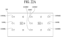
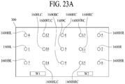
- a display apparatus comprises a display panel configured to display an image and including a first region, a second region, a third region, a fourth region, and a fifth region, at least one first sound generating device and at least one fourth sound generating device in a left region of a rear surface of the display panel and in the first region and the fourth region, at least one second sound generating device and at least one fifth sound generating device in a right region of the rear surface of the display panel and in the second region and the fifth region, and at least one third sound generating device in a center region of the rear surface of the display panel and in the third region, wherein the at least one first sound generating device, the at least one second sound generating device, and the at least one third sound generating device is configured to vibrate the display panel to generate sound, and the at least one fourth sound generating device and the at least one fifth sound generating device is configured to vibrate the display panel to generate sound in a direction upwards from the display panel.
- a display apparatus comprises a display panel configured to display an image and including a first region, a second region, a third region, a fourth region, and a fifth region, at least one first sound generating device and at least one fourth sound generating device in a left region of a rear surface of the display panel and in the first region and the fourth region, at least one second sound generating device and at least one fifth sound generating device in a right region of the rear surface of the display panel and in the second region and the fifth region, at least one third sound generating device in a center region of the rear surface of the display panel and in the third region, and a first partition separating sounds of the at least one first sound generating device, the at least one second sound generating device, and the at least one third sound generating device from sounds of the at least one fourth sound generating device and the at least one fifth sound generating device.
- the element is construed as including an error or tolerance range although there is no explicit description of such an error or tolerance range.
- a position relation between two parts is described as, for example, “on,” “over,” “under,” and “next,” one or more other parts may be disposed between the two parts unless a more limiting term, such as “just” or "direct(ly)” is used.
- first,” “second,” “A,” “B,” “(a),” “(b),” etc. may be used. These terms are intended to identify the corresponding elements from the other elements, and basis, order, or number of the corresponding elements should not limited by these terms.
- the expression that an element is “connected,” “coupled,” or “adhered” to another element or layer the element or layer can not only be directly connected or adhered to another element or layer, but also be indirectly connected or adhered to another element or layer with one or more intervening elements or layers "disposed” between the elements or layers, unless otherwise specified.
- At least one should be understood as including any and all combinations of one or more of the associated listed items.
- the meaning of "at least one of a first item, a second item, and a third item” denotes the combination of all items proposed from two or more of the first item, the second item, and the third item as well as the first item, the second item, or the third item.
- examples of a display apparatus may include a narrow-sense display apparatus such as an organic light emitting display (OLED) module or a liquid crystal module (LCM) including a display panel and a driver for driving the display panel.
- examples of the display apparatus may include a set device (or a set apparatus) or a set electronic apparatus such as a notebook computer, a TV, a computer monitor, an equipment apparatus including an automotive apparatus or another type of equipment display apparatus for vehicles, or a mobile electronic apparatus such as a smartphone or an electronic pad, which is a complete product (or a final product) including an LCM or an OLED module.
- examples of the display apparatus may include a narrow-sense display apparatus itself, such as an LCM or an OLED module, and a set apparatus that is a final consumer apparatus or an application product including the LCM or the OLED module.
- an LCM or an OLED module including a display panel and a driver may be referred to as a narrow-sense display apparatus
- an electronic apparatus that is a final product including an LCM or an OLED module may be referred to as a set apparatus.
- the narrow-sense display apparatus may include a display panel, such as an LCD or an OLED, and a source printed circuit board (PCB), which is a controller for driving the display panel.
- the set apparatus may further include a set PCB, which is a set controller electrically connected to the source PCB to overall control the set apparatus.
- a display panel applied to the present embodiment may use any type of display panel, such as a liquid crystal display panel, an organic light emitting diode (OLED) display panel, and an electroluminescent display panel, but is not limited to any particular display panel that may be vibrated by a sound generation device according to an embodiment of the present disclosure to output sound. Also, a shape or a size of a display panel applied to a display apparatus according to the present embodiment is not limited.
- the display panel may include a plurality of gate lines, a plurality of data lines, and a plurality of pixels respectively provided in a plurality of pixel areas defined by intersections of the gate lines and the data lines.
- the display panel may include an array substrate including a thin film transistor (TFT), which is a switching element for adjusting a light transmittance of each of the plurality of pixels, an upper substrate including a color filter and/or a black matrix, and a liquid crystal layer between the array substrate and the upper substrate.
- TFT thin film transistor
- the display panel may include a plurality of gate lines, a plurality of data lines, and a plurality of pixels respectively provided in a plurality of pixel areas defined by intersections of the gate lines and the data lines.
- the display panel may include an array substrate including a TFT, which is an element for selectively applying a voltage to each of the pixels, an organic light emitting device layer on the array substrate, and an encapsulation substrate disposed on the array substrate to cover the organic light emitting device layer.
- the encapsulation substrate may protect the TFT and the organic light emitting device layer from an external impact and may prevent water or oxygen from penetrating into the organic light emitting device layer.
- a layer provided on the array substrate may include an inorganic light emitting layer (for example, a nano-sized material layer, a quantum dot, or the like).
- the layer provided on the array substrate may include a micro light emitting diode.
- the display panel may further include a backing such as a metal plate attached to a rear surface of the display panel, but is not limited to the metal plate, and the display apparatus may include other structure.
- a backing such as a metal plate attached to a rear surface of the display panel, but is not limited to the metal plate, and the display apparatus may include other structure.
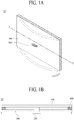
- FIG. 1A illustrates a display apparatus including a sound generating device according to an embodiment of the present disclosure.
- FIG. 1A illustrates a front surface of the display apparatus.
- the display apparatus 10 may include a display panel 100 for displaying an image and a sound generating device 200.
- the sound generating device 200 may vibrate the display panel 100 to generate a sound SW in a forward direction (or a front-surface region) FD with respect to the display panel 100.
- the sound generating device 200 may be disposed on a rear surface of the display panel 100.
- the rear surface of the display panel 100 may be referred to as one surface, a first surface, a rear surface, or a bottom or lower surface, but the term is not limited thereto.
- the display panel 100 may display an image (for example, an electronic image or a digital image) and may be implemented as any type of display panel such as a liquid crystal display panel, an organic light emitting diode (OLED) display panel, an electroluminescent display panel, etc.
- the display panel 100 may vibrate based on a vibration of the sound generating device 200 to output the sound SW in the forward direction FD with respect to the display panel 100.
- the display panel 100 may vibrate based on a vibration of the sound generating device 200 to output the sound SW in the forward direction FD while displaying an image.
- the display panel 100 may vibrate based on a vibration of the sound generating device 200 to output the sound SW in the forward direction FD in a state without displaying an image. Therefore, the display panel 100 according to an embodiment of the present disclosure may display an image and may output the sound SW.
- the display panel 100 may display an image according to a particular emission type, such as a top emission type, a bottom emission type, or a dual emission type, based on a structure of a pixel array layer including an anode electrode, a cathode electrode, and an organic compound layer.
- a particular emission type such as a top emission type, a bottom emission type, or a dual emission type
- visible light emitted from the pixel array layer may be irradiated onto a region in front of a base substrate to allow an image to be displayed.
- the visible light emitted from the pixel array layer may be irradiated onto a rearward region behind the base substrate to allow an image to be displayed.
- the sound generating device 200 may generate sound using the display panel 100 as a vibration plate.
- the sound generating device 200 may be referred to as an "actuator,” an “exciter,” or a “transducer,” but is not limited thereto.
- the sound generating device 200 may be a sound device for outputting sound according to an electrical signal.
- FIG. 1B is a cross-sectional view taken along line I-I' of FIG. 1A .
- the display apparatus 10 may include the sound generating device 200 and a supporting member 300.
- the supporting member 300 may support one or more of a rear surface and a side surface (or a lateral surface) of the display panel 100. Also, the sound generating device 200 may be fixed to the supporting member 300.
- the supporting member 300 may be, for example, a cover bottom.
- the supporting member 300 may include a middle cabinet, which may be coupled or connected to a cover bottom to surround the side surface (or a lateral surface) of the display panel 100 and accommodate one edge or periphery of the display panel 100 to support the display panel 100.
- the middle cabinet may include " ⁇ "-shaped cross-sectional surface.
- the supporting member 300 may include the cover bottom, or may include the cover bottom and the middle cabinet, but a structure thereof is not limited thereto.
- the supporting member 300 may include an arbitrary structure that supports the rear surface and/or the side surface of the display panel 100.
- the supporting member 300 may be a plate member that may be provided on the rear surface of the display panel 100 or over (e.g., over an entirety of) the display panel 100.
- the supporting member 300 may cover the display panel 100.
- the supporting member 300 may have a plate shape formed of a glass material, a metal material, or a plastic material.
- an edge or a sharp corner of the supporting member 300 may have a tetragonal (e.g., quadrilateral) shape or a curved shape through a chamfer process or a corner rounding process.
- the supporting member 300 of the glass material may include sapphire glass.
- the supporting member 300 including the metal material may be formed of one or more of aluminum (Al), an Al alloy, a magnesium (Mg) alloy, and an iron (Fe)-nickel (Ni) alloy.
- the supporting member 300 may have a stacked structure including a metal plate and a glass plate, the metal plate may have a thickness relatively thinner than the glass plate, and the glass plate may face the rear surface of the display panel 100.
- a rear surface of the display apparatus 10 may be used as a mirror surface due to the metal plate.
- embodiments are not limited to the above materials or shape.
- the supporting member 300 may include a hole into which the sound generating device 200 may be inserted or accommodated.
- the hole may be bored in a certain partial region of the supporting member 300 along a thickness direction of the supporting member 300 to have a circular shape or a polygonal shape, for the sound generating device 200 to be inserted or accommodated into the hole.
- the supporting member 300 may be referred to as a "cover bottom,” a “plate bottom,” a “back cover,” a “base frame,” a “metal frame,” a “metal chassis,” a “chassis base,” or an “m-chassis.”
- the supporting member 300 may be a supporter for supporting the display panel 100 and may be implemented as any type of frame or plate structure disposed on the rear surface of the display apparatus 10.
- An adhesive member 400 may be in an edge or periphery of the display panel 100 and the supporting member 300.
- the adhesive member 400 may be disposed between the rear surface of the display panel 100 and a front surface of the supporting member 300.
- the adhesive member 400 may attach the display panel 100 and the supporting member 300.
- the adhesive member 400 may include a double-sided tape, a single-sided tape, an adhesive, a bond, and/or the like, but is not limited thereto.
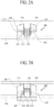
- FIGs. 2A and 2B are cross-sectional views illustrating the sound generating device according to an embodiment of the present disclosure.
- the sound generating device may be categorized into a first structure corresponding to an external magnetic type where a magnet may be outside a coil, and a second structure corresponding to an internal magnetic type where a magnet may be inside a coil.
- the first structure may be referred to as a dynamic type or external magnetic type
- the second structure may be referred to as a micro type or internal magnetic type.
- FIG. 2A illustrates the first structure
- FIG. 2B illustrates the second structure
- the sound generating device 200 may include plates 210 and 210', a magnet 220 on the plate 210, a center pole 230 on the plate 210, a bobbin 250 disposed around the center pole 230, and a coil 260 wound on an outer surface of the bobbin 250.
- the magnet 220 may be disposed on the first plate 210, and the second plate 210' may be disposed on the magnet 220.
- the first plate 210 and the second plate 210' may support the magnet 220 and fix the sound generating device 200 to the supporting member 300.
- the first plate 210 may be fixed to a supporting hole in the supporting member 300, and the magnet 220 may be fixedly supported between the first plate 210 and the second plate 210'.
- At least one of the first plate 210 and the second plate 210' may be formed of a magnetic material such as iron (Fe).
- the first plate 210 and the second plate 210' are not limited to these terms, and they may be referred to as yokes.
- the magnet 220 may use a sintered magnet of barium ferrite, and the magnet 220 may be formed of iron (III) oxide (Fe 2 O3), barium carbonate (BaCO 3 ; "witherite"), neodymium (Nd) magnet, strontium ferrite (Fe 12 O 19 Sr) with improved magnetic component, an alloy cast magnet including aluminum (Al), nickel (Ni), and cobalt (Co), and/or the like.
- the neodymium magnet may be neodymium-iron-boron (Nd-Fe-B).
- embodiments are not limited to these materials or examples.
- a frame 240 may be disposed on the second plate 210' along the periphery of the first plate 210.
- a center pole 230 may be disposed on a center area of the first plate 210.
- the center pole 230 and the first plate 210 may be formed as one body or a single structure body.
- the center pole 230 may be referred to as pole pieces. As another example, pole pieces may be further on the center pole 230.
- a bobbin 250 may surround a periphery of a center pole 230.
- a coil 260 may be wound around a certain lower region (for example, a lower region of the bobbin 250) of the bobbin 250.
- the coil 260 may be wound around a lower outer surface of the bobbin 250, and a current or a voice signal for generating a sound may be applied to the coil 260.
- the bobbin 250 may be implemented as a ring (or cylindrical) structure including a material obtained by processing pulp or paper, aluminum or magnesium or an alloy thereof, synthetic resin such as polypropylene, or a polyamide-based fiber, but is not limited thereto.
- the bobbin 250 and the coil 260 may be referred to as a voice coil.
- the damper 270 may be disposed or connected between some area of an upper portion of the bobbin 250 and the frame 240.
- the damper 270 may be referred to as an edge, a spider, a suspension, and/or the like, but the term is not limited thereto.
- FIG. 2B illustrates the second structure where a magnet may be disposed inside a coil.
- the sound generating device 200' of the second structure includes a magnet 220 on a first plate 210, a center pole 230 on the magnet 220, a bobbin 250 disposed around the magnet 220 and the center pole 230, and a coil 260 wound on an outer surface of the bobbin 250.
- the first plate 210 may be fixed to a supporting hole in the supporting member 300.
- the magnet 220 may be disposed on the first plate 210, and the center pole 230 may be disposed on the magnet 220.
- the center pole 230 may be referred to as pole pieces.
- pole pieces may be further provided on the center pole 230.
- the bobbin 250 may surround the magnet 220 and the center pole 230, and the coil 260 may be wound around the outer surface of the bobbin 250.
- a second plate 210' may be disposed at the outer periphery of the first plate 210, and a frame 240 may be disposed at the periphery of the second plate 210'.
- a damper 270 may be disposed between the frame 240 and the bobbin 250.
- the second structure In comparison to the first structure where the magnet may be disposed outside the coil, the second structure has advantages of small in leakage magnetic flux and may reduce an entire size of the sound generating device.
- the sound generating device applied to the display apparatus is not limited to the structures of FIGs. 2A and 2B . It may be possible to apply another kind of sound generating device, which may directly vibrate a display panel to generate sound.
- FIGs. 3A and 3B illustrate a sound generating method of the sound generating device with the first structure according to an embodiment of the present disclosure.
- FIG. 3A shows a state in which a current may be applied.
- the center pole 230 connected with a lower surface of the magnet 220 may be a north (N)-pole
- the second plate 210' connected with an upper surface of the magnet 220 may be a south (S)-pole, whereby an external magnetic field is generated around the coil 260.
- N north
- S south
- an application magnetic field may be generated around the coil 260, whereby a force for moving the bobbin 250 to an upper portion may be generated by the application magnetic field and an external magnetic field.
- an application magnetic field is generated around the coil 260.
- the entire bobbin 250 may be guided by the center pole 230, and may move to upper portion according to Fleming's Left-Hand Rule for Motors based on the application magnetic field and the external magnetic field generated by the magnet 220.
- one surface of the bobbin 250 may be contact a rear surface of the display panel 100.
- the bobbin 250 may vibrate the display panel 100 in an upward direction (illustrated by an arrow) according to whether a current is applied to the coil 260 or not, and a sound wave (or sound) may be generated by the vibration of the display panel 100.
- a force for moving the bobbin 250 to a lower side may be generated based on the principle similar to description given above with reference to FIG. 3A , and the display panel 100 may vibrate in a downward direction (illustrated by an arrow).
- the damper 270 is disposed between the frame 240 and a portion of an upper portion of the bobbin 250.
- the damper 270 may be provided in a wrinkled or creased structure having elasticity and may be contracted and relaxed based on a vertical motion of the bobbin 250 to control a vertical vibration of the bobbin 250.
- the damper 270 may be connected to the bobbin 250 and the frame 240.
- the vertical vibration of the bobbin 250 may be controlled by a restoring force of the damper 270.
- the bobbin 250 may be restored to an original position by the restoring force of the damper 270.
- the display panel 100 may vertically vibrate based on an application direction and level of a current applied to the coil 260, to thereby generate the sound wave by the vibration.
- FIGs. 4A and 4B illustrate a sound generating method of the sound generating device with the second structure according to an embodiment of the present disclosure.
- FIG. 4A illustrates a state in which a current may be applied.
- the second plate 210' may be an S pole
- the center pole 230 connected to an upper surface of the magnet 220 may be an N pole, whereby an external magnetic field may be generated around the coil 260.
- the S-pole and the N-pole may switch therebetween, and if the S-pole and the N-pole switches therebetween, the sound generating device may identically operate by correcting a winding direction of the coil 260.
- an application magnetic field may be generated around the coil 260, and a force for moving the bobbin 250 to an upper side may be generated by the application magnetic field and an external magnetic field.
- an application magnetic field may be generated around the coil 260.
- the entire bobbin 250 may be guided by the center pole 230 and may move to the upper side according to Fleming's Left-Hand Rule for Motors based on the application magnetic field and the external magnetic field generated by the magnet 220.
- one surface of the bobbin 250 may contact a rear surface of the display panel 100.
- the bobbin 250 may vibrate the display panel 100 in an upward direction (illustrates by an arrow) according to whether a current is applied to the coil 260 or not, and a sound wave (or sound) may be generated by the vibration of the display panel 100.
- a force for moving the bobbin 250 to a lower side may be generated according to the principle similar to description given above with reference to FIG. 4A , and the display panel 100 may vibrate in a downward direction (illustrated by an arrow).
- the damper 270 may be disposed between the frame 240 and a partial portion of an upper portion of the bobbin 250.
- the damper 270 may be provided in a wrinkled or creased structure having elasticity and may be contracted and relaxed based on a vertical motion of the bobbin 250 to control a vertical vibration of the bobbin 250.
- the damper 270 may be connected to the bobbin 250 and the frame 240.
- the vertical vibration of the bobbin 250 may be controlled by a restoring force of the damper 270.
- the bobbin 250 may be restored to an original position by the restoring force of the damper 270.
- the display panel 100 may vertically vibrate based on an application direction and level of a current applied to the coil 260, to thereby generate the sound wave by the vibration.
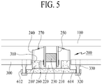
- FIG. 5 illustrates a display apparatus including a sound generating device according to an embodiment of the present disclosure.
- any of a sound generating device having the first structure and a sound generating device having the second structure may be applied.
- a sound generating device having the second structure will be described as an example.
- a sound generating device 200 may include a diameter enlargement part 614.
- the diameter enlargement part 614 may be provided as one body or a single structure body with a first plate 210 of the sound generating device 200.
- a first plate 210 of the sound generating device 200 may not have a cylindrical shape or a cylinder shape.
- One side of the first plate 210 may include a protrusion that may be greater than a diameter of the other portion of the first plate 210.
- the protrusion region having an enlarged diameter may be referred to as a diameter enlargement part 614.
- the diameter enlargement part 614 may have a ring shape.
- an extension part 612 for fixing the sound generating device 200 may be in a portion of the diameter enlargement part 614.
- a screw 320 and a nut 330 may be in the extension part 612.
- the sound generating device 200 may be coupled or connected to a supporting member 300 by the screw 320 using the nut 330 fixed to the supporting member 300.
- the nut 330 may be, for example, a self-clinching nut.
- An example of the self-clinching nut may include a PEM® nut, and the present embodiment is not limited thereto. Therefore, the sound generating device 200 may be accommodated into a supporting hole 310 in the supporting member 300.
- the self-clinching nut is used, a portion of a vibration generated by the sound generating device 200 may be absorbed by the self-clinching nut, which may be the nut 330. Thus, a vibration transferred to the supporting member 300 may be reduced. And, the display panel 100 may be attached or coupled on the bobbin 250 of the sound generating device 200.
- a sound generating device may be coupled or connected to a display panel through a supporting hole of a supporting member. Therefore, a rear surface of the supporting member may need the supporting hole, and there may be a problem where external particles may penetrate into the inside of the display panel through the supporting hole. Also, because the sound generating device may be exposed at the rear surface of the supporting member, a sense of beauty in appearance may be reduced by the sound generating device exposed at the rear surface of the supporting member.
- a protection cover for protecting the sound generating device may be needed for preventing damage of the sound generating device exposed at the rear surface of the supporting member
- a process of adding the protection cover may be needed or a thickness of the sound generating device may be thickened due to the protection cover. Therefore, the present inventors have performed various experiments for configuring the sound generating device, which may be provided in the display panel without being coupled or connected to the supporting member by the supporting hole of the supporting member. Through the various experiments, the present inventors have recognized that a thickness of the sound generating device should be reduced for configuring the sound generating device in the display panel.
- the present inventors When the sound generating device is thick, the present inventors have recognized that there may be a problem in which a thickness of the display panel may be thickened, the image quality of the display panel or an image displayed by the display panel may be adversely affected, and a sense of beauty in appearance is reduced. Also, since a plurality of sound generating devices should be provided for realizing a stereo sound, the present inventors have recognized that a thickness of the sound generating device should be reduced. Therefore, to reduce a thickness of the sound generating device, it may be required to reduce a thickness of element included in the sound generating device. For example, when a thickness of a magnet is reduced, a magnetic flux density may decrease, causing a problem in which a sound pressure may be lowered.
- a height (or a thickness) of a bobbin when a height (or a thickness) of a bobbin is lowered, a winding width of a coil wound around the bobbin may be reduced.
- a magnetic force of the sound generating device may be weakened, causing a problem in which an articulation of a tone may be reduced or a sound pressure may be lowered.
- a line through which an electrical signal may be transferred to the coil may cause a problem in which an interference sound may occur in the sound generating device due to interference by a damper. Therefore, through various experiments, the present inventors have invented a sound generating device having a new structure, in which a thickness of the sound generating device may be reduced by widening an area of the sound generating device, and a sound is not affected. This will be described below with reference to FIGs. 6 to 12 .
- FIG. 6 illustrates a display apparatus including a sound generating device according to another embodiment of the present disclosure.
- any of a sound generating device having the first structure and a sound generating device having the second structure may be applied.
- a sound generating device having the second structure will be described as an example.
- a display apparatus 20 may include a display panel 100 and a sound generating device 1600.
- An encapsulation substrate 102 may be disposed on a rear surface of the display panel 100.
- the encapsulation substrate 102 may protect a thin film transistor (TFT), a light emitting device layer, and the like disposed in the display panel 100 from an external impact and may prevent water or moisture, or oxygen from penetrating into the light emitting device layer.
- TFT thin film transistor
- the encapsulation substrate may be referred to as a sealing substrate or protection substrate.
- the sound generating device 1600 may include a magnet 1620 on a yoke 1610, a center pole 1630 on the magnet 1620, a bobbin 1650 around the magnet 1620 and the center pole 1630, and a coil 1660 wound around an outer portion of the bobbin 1650.
- the coil 1660 When the coil 1660 is wound to surround an outer circumference surface of the bobbin 1650, heat occurring in the coil 1660 may be transferred to the bobbin 1650, and the coil 1660 may include a material which is relatively good in heat dissipation characteristic, for decreasing an image quality defect affecting the display panel 100 due to the heat of the bobbin 1650.
- an eccentric vibration (or a horizontal vibration) may occur due to a vertical vibration, and the eccentric vibration of the bobbin 1650 may be affected by a weight of the bobbin 1650.
- a weight of the bobbin 1650 may be affected by a weight of the coil 1660. Therefore, when a weight of the coil 1660 is reduced, the eccentric vibration of the bobbin 1650 may decrease.
- the coil 1660 may have a relatively good heat dissipation characteristic because thermal conductivity thereof is better than that of copper which is a material of a general coil, and may include an Al material which has a relatively good heat dissipation characteristic and is relatively lightweight compared to copper.
- the yoke 1610 may be a plate, but the term is not limited thereto.
- the coil 1660 may include an Al layer (or a first metal layer) for dissipating heat and a metal covering layer (or a second metal layer) surrounding the Al layer.
- the metal covering layer may include one of Cu, Ag, and Au.
- the coil 1660 may be a copper clad aluminum wire is covered by copper.
- the metal covering layer may be formed as a thin film type outside the first metal layer, and thus, may not greatly affect an increase in weight of the coil 1660. Therefore, a weight of the coil 1660 according to an embodiment of the present disclosure may decrease by about 60% compared to a coil including only Cu or a Cu wire.
- the bobbin 1650 may include a structure including a material obtained by processing pulp or paper, Al or Mg or an alloy thereof, or synthetic resin such as polyimide.
- the bobbin 1650 may be implemented with a polyimide film which is relatively good in heat dissipation characteristic and is relatively lightweight, for preventing an image quality defect of the display panel 100 caused by heat occurring in the coil 1660.
- the polyimide film may have physical properties which are not changed within a wide temperature range from -273°C to 400°C and may have a heat resistance, electrical insulation, flexibility, and nonflammable.
- the polyimide film may enhance the reliability of the bobbin 1650, and the occurrence of heat caused by a vibration of the bobbin 1650 may be reduced based on an excellent heat dissipation characteristic.
- the polyimide film may be KAPTON and may be a condensation of pyromellitec dianhydride and 4,4'-oxydianiline, but is not limited thereto.
- a frame 1640 may be disposed at an outer portion of the yoke 1610.
- a damper 1670 may be disposed between the frame 1640 and the bobbin 1650.
- a description of the sound generating device 1600 is the same as the description of FIGs. 2A and 2B , and thus, a detailed description is omitted.
- the display panel 100 may be attached or connected on the bobbin 1650 of the sound generating device 1600 by using an adhesive member 402.
- a bobbin ring 1652 may be further provided on the bobbin 1650.
- the bobbin ring 1652 may be interposed between the bobbin 1650 and the display panel 100 and may transfer a vibration of the bobbin 1650 to the display panel 100.
- FIG. 6 an example where the bobbin ring 1652 is disposed at a whole portion of the bobbin 1650 will be described.
- the present embodiment is not limited thereto, and the bobbin ring 1652 may be disposed at a position at which the bobbin 1650 is disposed.
- the bobbin ring 1652 may be attached or connected on the display panel 100 by the adhesive member 402.
- the adhesive member 402 may include a double-sided tape, a single-sided tape, an adhesive, and a bond, but is not limited thereto. As in FIG. 6 , the adhesive member 402 may be provided at a portion, on which the sound generating device 1600 is attached or connected, of the display panel 100. However, the present embodiment is not limited thereto, and the adhesive member 402 may be provided on the whole rear surface of the display panel 100. For example, the adhesive member 402 may be provided on a whole surface between the rear surface of the display panel 100 and the sound generating device 1600.
- a partition 700 may be disposed between the display panel 100 and the supporting member 300. For example, the partition 700 may be disposed between the encapsulation substrate 102 of the display panel 100 and the supporting member 300.
- a connection or coupling member 1710 may be disposed at the sound generating device 1600 so that the sound generating device 1600 is disposed in the display panel 100.
- the yoke 1610 may include an extension portion 1612.
- the connection member 1710 may be disposed at the extension portion 1612 of the yoke 1610.
- a screw tap may be formed by enlarging a thickness of the yoke 1610, and then, may be screw-fastened.
- the screw tap may be formed as a passive tap, a mechanical tap, a gas screw tap, or a master tap, but is not limited thereto.
- the connection member 1710 may be disposed in the supporting member 300.
- the connection member 1710 may include a screw 1720 and a nut 1730.
- the screw 1720 and the nut 1730 may be disposed in the supporting member 300, and the sound generating device 1600 may be fixed to an inner portion of the supporting member 300 by the screw 1720 and the nut 1730.
- the nut 1730 may be a self-clinching nut.
- An example of the self-clinching nut may include PEM® nut, but embodiments are not limited thereto.
- the sound generating device 1600 may be coupled or connected to the supporting member 300 by the nut 1730 using a press-fitting manner without a supporting hole of the supporting member 300.
- the press-fitting manner may use a saw-toothed press-fitting manner, and embodiments are not limited to a coupling manner or a coupling shape. Therefore, the sound generating device 1600 may be disposed in the display panel 100.
- the sound generating device 1600 may be disposed or coupled between the display panel 100 and the supporting member 300 by the connection member 1710. Therefore, a sound generating device may be disposed or coupled in a display panel, and thus, a supporting hole of a supporting member may not be provided, thereby preventing penetration of external particles through the supporting hole of the supporting member.
- a display apparatus having an aesthetic appearance may be provided, and damage of the sound generating device may be prevented.
- FIG. 7 illustrates a display apparatus including a sound generating device according to another embodiment of the present disclosure.
- any of a sound generating device having the first structure and a sound generating device having the second structure may be applied.
- a sound generating device having the second structure will be described as an example.
- the display apparatus 30 may include a display panel 100 and a sound generating device 1600.
- An encapsulation substrate 102 may be disposed on a rear surface of the display panel 100.
- the encapsulation substrate 102 may protect a thin film transistor (TFT), a light emitting device layer, and the like each disposed in the display panel 100 from an external impact and may prevent water or moisture, or oxygen from penetrating into the light emitting device layer.
- TFT thin film transistor
- the encapsulation substrate may be referred to as a sealing substrate or protection substrate.
- the sound generating device 1600 may include a magnet 1620 on a yoke 1610, a center pole 1630 on the magnet 1620, a bobbin 1650 around the magnet 1620 and the center pole 1630, and a coil 1660 wound around an outer portion of the bobbin 1650.
- the yoke 1610 may be a plate, but the term is not limited thereto.
- a frame 1640 may be disposed at an outer portion of the yoke 1610 or outside the yoke 1610.
- a damper 1670 may be disposed between the frame 1640 and the bobbin 1650.
- a description of the sound generating device 1600 may be the substantially similar to the description given above with reference to FIGs. 2A and 2B , and thus, a detailed description may be omitted.
- the display panel 100 may be attached or connected to the bobbin 1650 of the sound generating device 1600 by an adhesive member 402.
- a bobbin ring 1652 may be further provided on the bobbin 1650.
- the bobbin ring 1652 may be between the bobbin 1650 and the display panel 100 and may transfer a vibration of the bobbin 1650 to the display panel 100.
- FIG. 7 an example where the bobbin ring 1652 is disposed all over the bobbin 1650 will be described. However, embodiments are not limited thereto, and the bobbin ring 1652 may be disposed at a position at which the bobbin 1650 is disposed.
- the bobbin ring 1652 may be attached or connected to the display panel 100 by the adhesive member 402.
- the adhesive member 402 may include a double-sided tape, a single-sided tape, an adhesive, and a bond, but embodiments are not limited thereto. As in FIG. 7 , the adhesive member 402 may be provided at a portion, on which the sound generating device 1600 is attached or connected, of the display panel 100. However, embodiments are not limited thereto. For example, the adhesive member 402 may be provided on the whole rear surface of the display panel 100. For example, the adhesive member 402 may be provided on a whole surface between the rear surface of the display panel 100 and the sound generating device 1600. Also, a partition 700 may be disposed between the display panel 100 and the supporting member 300. For example, the partition 700 may be disposed between the encapsulation substrate 102 of the display panel 100 and the supporting member 300.
- a connection or coupling member 1710 may be disposed at a sound generating device 1600 for the sound generating device 1600 to be placed or disposed in a display panel 100.
- a frame 1640 may include an extension portion 1642.
- the connection member 1710 may be disposed at the extension portion 1642 of the frame 1640.
- the connection member 1710 may include a screw 1720 and a nut 1730.
- the screw 1720 and the nut 1730 may be disposed in the supporting member 300, and the sound generating device 1600 may be fixed to an inner portion of the supporting member 300 or in the supporting member 300 by the screw 1720 and the nut 1730.
- the nut 1730 may be a self-clinching nut.
- An example of the self-clinching nut may include PEM® nut, but embodiments are not limited thereto.
- the sound generating device 1600 may be coupled or connected to the supporting member 300 by the nut 1730 by a press-fitting manner without a supporting hole of the supporting member 300.
- the press-fitting manner may use a saw-toothed press-fitting manner, and embodiments are not limited to a coupling or connection manner or a coupling or connection shape. Therefore, the sound generating device 1600 may be disposed in the display panel 100.
- the sound generating device 1600 may be disposed or coupled between the display panel 100 and the supporting member 300 by the connection member 1710. Therefore, a sound generating device may be disposed or coupled in a display panel, and thus, a supporting hole of a supporting member may not be provided, thereby preventing penetration of external particles through the supporting hole of the supporting member.
- a display apparatus having an aesthetic appearance may be provided, and damage of the sound generating device may be prevented.
- the encapsulation substrate 102 disposed on the rear surface of the display panel 100 may be formed of a ferromagnetic material (for example, a material such as invar which is an iron-nickel (Fe-Ni) alloy, and thus, the present inventors have recognized that a magnetic force of a magnet of the sound generating device provided in the display panel 100 is absorbed by the encapsulation substrate, and due to this, is lost. The present inventors have recognized that the encapsulation substrate is attracted by the magnetic force of the magnet, and thus, the sound generating device is pressed, whereby the sound generating device is unable to vibrate vertically.
- a ferromagnetic material for example, a material such as invar which is an iron-nickel (Fe-Ni) alloy
- the present inventors have recognized that the encapsulation substrate is attracted by the magnetic force of the magnet and is adhered to the sound generating device, and due to this, a space enabling the sound generating device to vibrate is lost. Therefore, through various experiments, the present inventors have invented a display apparatus where the leakage of a magnetic force of a sound generating device is reduced, and a space enabling the sound generating device to vibrate is not reduced. This will be described below with reference to FIGs. 8 to 12 .
- FIG. 8 illustrates a display apparatus including a sound generating device according to another embodiment of the present disclosure.
- any of a sound generating device having the first structure and a sound generating device having the second structure may be applied.
- a sound generating device having the second structure will be described as an example.
- the display apparatus 40 may include a display panel 100 and a sound generating device 1600.
- the sound generating device 1600 may be disposed between the display panel 100 and a supporting member 300.
- the sound generating device 1600 may be disposed in the display panel 100.
- a description of the sound generating device 1600 may be substantially similar to descriptions given above with reference to FIGs. 2A, 2B , 6, and 7 , and thus, is omitted.
- the sound generating device 1600 may include a magnet 1620 on a yoke 1610, a center pole 1630 on the magnet 1620, a bobbin 1650 around the magnet 1620 and the center pole 1630, and a coil 1660 wound around an outer portion of the bobbin 1650.
- the yoke 1610 may be a plate, but the term is not limited thereto.
- a frame 1640 may be disposed at an outside portion of the yoke 1610.
- a damper 1670 may be disposed between the frame 1640 and the bobbin 1650.
- a bobbin ring 1652 may be further provided on the bobbin 1650. In FIG. 8 , an example where the bobbin ring 1652 is disposed all over the bobbin 1650 will be described. However, embodiments are not limited thereto, for example, the bobbin ring 1652 may be disposed at a position at which the bobbin 1650 is disposed.
- a connection or coupling member 1710 may be disposed at the sound generating device 1600 so that the sound generating device 1600 is disposed in the display panel 100.
- the yoke 1610 may include an extension portion 1612.
- the connection member 1710 may be disposed at the extension portion 1612 of the yoke 1610.
- a screw tap may be formed by enlarging a thickness of the yoke 1610, and then, may be screw-fastened.
- the screw tap may be formed as a passive tap, a mechanical tap, a gas screw tap, or a master tap, but embodiments are not limited thereto.
- the connection member 1710 may be disposed in the supporting member 300.
- the connection member 1710 may include a screw 1720 and a nut 1730.
- the screw 1720 and the nut 1730 may be disposed in the supporting member 300, and the sound generating device 1600 may be fixed to an inner portion of the supporting member 300 by the screw 1720 and the nut 1730.
- the nut 1730 may be a self-clinching nut.
- An example of the self-clinching nut may include PEM® nut, but embodiments are not limited thereto.
- a heat dissipation member 600 may be further disposed on a rear surface of the display panel 100, for decreasing heat occurring when the sound generating device 1600 is vibrating.
- the heat dissipation member 600 may be disposed on a rear surface of an encapsulation substrate 102 using an adhesive member.
- the heat dissipation member 600 may be configured to cover the sound generating device 1600 or to have a size that is greater than that of the sound generating device 1600 and may have a polygonal plate shape or a circular plate shape having a certain thickness, but embodiments are not limited thereto.
- the heat dissipation member 600 may be a heat dissipation sheet or a heat dissipation tape formed of a metal material that has high thermal conductivity like aluminum (Al), copper (Cu), or silver (Ag) and an alloy thereof, but embodiments are not limited thereto. Accordingly, because the heat dissipation member 600 is provided, an influence of heat occurring when the sound generating device is vibrating may be reduced on the image quality of the display panel 100.
- a partition 700 may be disposed between the display panel 100 and the supporting member 300.
- the partition 700 may be disposed between the heat dissipation member 600 disposed on the rear surface of the display panel 100 and the supporting member 300.
- FIG. 9 illustrates a display apparatus including a sound generating device according to another embodiment of the present disclosure.
- any of a sound generating device having the first structure and a sound generating device having the second structure may be applied.
- a sound generating device having the second structure will be described as an example.
- the display apparatus 50 may include a display panel 100 and a sound generating device 1600.
- the sound generating device 1600 may be disposed between the display panel 100 and a supporting member 300.
- the sound generating device 1600 may be disposed in the display panel 100.
- a description of the sound generating device 1600 may be substantially similar to descriptions given above with reference to FIGs. 2A, 2B , 6, and 7 , and thus, is omitted.
- the sound generating device 1600 may include a magnet 1620 on a yoke 1610, a center pole 1630 on the magnet 1620, a bobbin 1650 around the magnet 1620 and the center pole 1630, and a coil 1660 wound around an outer portion of the bobbin 1650.
- the yoke 1610 may be a plate, but the term is not limited thereto.
- a frame 1640 may be disposed outside the yoke 1610.
- a damper 1670 may be disposed between the frame 1640 and the bobbin 1650.
- a bobbin ring 1652 may be further provided on the bobbin 1650. In FIG. 9 , an example where the bobbin ring 1652 is disposed all over the bobbin 1650 will be described. However, embodiments are not limited thereto, and the bobbin ring 1652 may be disposed at a position at which the bobbin 1650 is disposed.
- a connection or coupling member 1710 may be disposed at a sound generating device 1600 so that the sound generating device 1600 is disposed in a display panel 100.
- a frame 1640 may include an extension portion 1642.
- the connection member 1710 may be disposed at the extension portion 1642 of the frame 1640.
- the connection member 1710 may include a screw 1720 and a nut 1730.
- the screw 1720 and the nut 1730 may be disposed in the supporting member 300, and the sound generating device 1600 may be fixed to an inner portion of the supporting member 300 by the screw 1720 and the nut 1730.
- the nut 1730 may be a self-clinching nut.
- An example of the self-clinching nut may include PEM® nut, but embodiments are not limited thereto.
- a heat dissipation member 600 may be further disposed on a rear surface of the display panel 100, for decreasing heat occurring when the sound generating device 1600 is vibrating.
- the heat dissipation member 600 may be disposed on a rear surface of an encapsulation substrate 102 using an adhesive member.
- the heat dissipation member 600 may be configured to cover the sound generating device 1600 or to have a size that is greater than that of the sound generating device 1600 and may have a polygonal plate shape or a circular plate shape having a certain thickness, but embodiments are not limited thereto.
- the heat dissipation member 600 may be a heat dissipation sheet or a heat dissipation tape formed of a metal material which is high in thermal conductivity like Al, Cu, or Ag and an alloy thereof, but embodiments are not limited thereto. Accordingly, because the heat dissipation member 600 is provided, an influence of heat occurring when the sound generating device is vibrating may be reduced on the image quality of the display panel 100.
- a partition 700 may be disposed between the display panel 100 and the supporting member 300.
- the partition 700 may be disposed between the heat dissipation member 600 disposed on the rear surface of the display panel 100 and the supporting member 300.
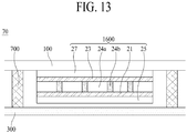
- FIGs. 10A to 10D illustrate a sound generating device according to another embodiment of the present disclosure.
- FIG. 10A illustrates one sound generating device or one-array sound generating device.
- FIG. 10B illustrates a two-array where two sound generating devices are provided.
- FIG. 10C illustrates a four-array where four sound generating devices are provided.
- FIG. 10D illustrates a six-array where six sound generating devices are provided.
- the sound generating device according to the present embodiment may be configured as one sound generating device or a sound generating device having two or more-array structure, but embodiments are not limited thereto.
- the sound generating device having a first structure or a second structure described above with reference to FIGs. 2A and 2B may be applied to the sound generating device according to an embodiment of the present disclosure.
- the sound generating device may be a sound generating module, but the term is not limited thereto.
- an area of a damper may be widely set for decreasing a thickness of a sound generating device, and for enhancing the performance of a magnet.
- the damper may be formed of stainless steel, Cu, and/or the like, and thus, may be a line for applying a sound signal to the sound generating device.
- a damper 1670 may be disposed on a frame 1640.
- the one-array sound generating device 1600 may be referred to as a single type.
- the frame 1640 may be a yoke, but the term is not limited thereto.
- the damper 1670 may be configured to perform a function of a line or a power supplying member, and thus, may include a first damper 1670a to which positive (+) power (or a sound signal) is applied and a second damper 1670b to which negative (-) power (or a sound signal or a voice signal) is applied.
- the damper 1670 may be divided with respect to a widthwise direction.
- the first damper 1670a, to which the positive power is applied may be an upper portion with respect to the front of the drawing and the second damper 1670b, to which the negative power is applied, may be a lower portion with respect to the front of the drawing.
- first damper 1670a may be connected to a first line 242a
- second damper 1670b may be connected to a second line 242b
- the first line 242a and the second line 242b may be a line pad, but the term is not limited thereto.
- a shape 'S' of the damper 1670 may be provided as an S-shape or a zigzag shape.
- the first line 242a and the second line 242b may have a length that is longer than a distance between the frame 1640 and the bobbin 1660, thereby decreasing a thickness of the sound generating device 1600.
- a portion illustrated by 'C' and a portion illustrated by 'D' may be configured to have the same thickness and different widths, and disconnection may be avoided or prevented from occurring in an overlapping portion therebetween.
- dampers 1670a and 1670b may be disposed on a frame 1640.
- the two-array sound generating device 1900 may be referred to as a twin type.
- the dampers 1670a and 1670b may be connected to each other in parallel.
- the dampers 1670a and 1670b may be configured to perform a function of a line or a power supplying member, and thus, may include a first damper 1670a to which positive (+) power is applied and a second damper 1670b to which negative (-) power is applied.
- the dampers 1670a and 1670b may be divided with respect to a widthwise direction.
- the first damper 1670a, to which the positive power is applied may be an upper portion with respect to the front of the drawing and the second damper 1670b, to which the negative power is applied, may be a lower portion with respect to the front of the drawing.
- first damper 1670a may be connected to a first line 242a
- second damper 1670b may be connected to a second line 242b
- two first dampers 1670a may be connected as one body and may be connected to the first line 242a
- two second dampers 1670b may be connected as one body, and may be connected to the second line 242b.
- a description of a shape of the dampers 1670a and 1670b may be the same as or similar to description give above with respect to FIG. 10A .
- dampers 1670a and 1670b may be disposed on a frame 1640.
- the four-array sound generating device 2020 may be referred to as a quad type.
- the dampers 1670a and 1670b may be connected to one another in parallel and serially.
- the dampers 1670a and 1670b may be configured to perform a function of a line or a power supplying member, and thus, may include a first damper 1670a to which positive (+) power is applied and a second damper 1670b to which negative (-) power is applied.
- the dampers 1670a and 1670b may be divided with respect to a widthwise direction.
- the first damper 1670a, to which the positive power is applied may be an upper portion or a lower portion with respect to the front of the drawing and the second damper 1670b, to which the negative power is applied, may be a lower portion or an upper portion with respect to the front of the drawing.
- Each of a plurality of first dampers 1670a may be connected to a first line 242a, and each of a plurality of second dampers 1670b may be connected to a second line 242b.
- first dampers 1670a may be connected as one body and may be connected to the first line 242a
- second dampers 1670b may be connected as one body and may be connected to the second line 242b.
- a description of a shape of the dampers 1670a and 1670b may be the same as or similar to description give above with respect to FIG. 10A .
- dampers 1670a and 1670b may be disposed on a frame 1640.
- the six-array sound generating device 2000 may be referred to as a hexa type.
- the dampers 1670a and 1670b may be connected to one another in parallel and serially.
- the dampers 1670a and 1670b may be configured to perform a function of a line, and thus, may include a first damper 1670a to which positive (+) power is applied and a second damper 1670b to which negative (-) power is applied.
- the dampers 1670a and 1670b may be divided with respect to a widthwise direction. For example, in dampers disposed in a left portion and a right portion of the drawing, the first damper 1670a, to which the positive power is applied, may be a left portion with respect to the front of the drawing and the second damper 1670b, to which the negative power is applied, may be a right portion with respect to the front of the drawing.
- first damper 1670a disposed at a center of the drawing may be a right portion, and the second damper 1670b may be a left portion.
- each of a plurality of first dampers 1670a may be connected to a first line 242a
- each of a plurality of second dampers 1670b may be connected to a second line 242b.
- two first dampers 1670a may be connected as one body and may be connected to the first line 242a
- two second dampers 1670b may be connected as one body and may be connected to the second line 242b.
- a description of a shape of the dampers 1670a and 1670b may be the same as or similar to description give above with respect to FIG. 10A .
- a sound generating device may be disposed without a supporting hole of a supporting member, and thus, a degree of freedom in disposition of the sound generating device may be enhanced.
- FIGs. 11A and 11B illustrate a sound generating device according to another embodiment of the present disclosure.
- FIG. 11A is a diagram seen from above with respect to the sound generating device according to another embodiment of the present disclosure
- FIG. 11B is a diagram seen from below with respect to the sound generating device according to another embodiment of the present disclosure.
- a two-array sound generating device will be described as an example.
- one structure may be further provided at one of a peripheral portion and a center portion of a damper 1670.
- a first structure 1400 may be disposed near the damper 1670.
- the first structure 1400 may be disposed to surround the damper 1670.
- the first structure 1400 may reinforce stiffness of the damper 1670.
- the first structure 1400 may be formed of aluminum (Al), magnesium (Mg), and/or the like, but embodiments are not limited thereto.
- a sound generating device configured as a two-array is illustrated, and when one sound generating device is provided, a first structure may be disposed near a damper.
- One or more second structures may be further provided at the center portion of the damper 1670.
- the second structures may include a 2-1 st structure 1674a, a 2-2 nd structure 1674b, a 2-3 rd structure 1674c, and a 2-4 th structure 1674d.
- the second structures 1674 may reinforce stiffness of the center portion of the damper 1670.
- FIG. 11A a sound generating device provided as a two-array is illustrated, and when one sound generating device is provided, at least one second structure may be disposed at a center portion of a damper 1670.
- a first structure and/or a second structure may be disposed at one of the peripheral portion and the center portion of the damper 1670.
- a screw hole 1720a may be further provided in the first structure 1400.
- a sound generating device may be disposed in a display panel by using the screw hole 1720a.
- a slit 405s may be further disposed on the bobbin ring 1652.
- the slit 405s may be provided for an attachment function of an adhesive member between the two-array sound generating devices and may remove an air bubble of the adhesive member.
- the slit 405s may prevent a high-pitched sound from being degraded by an air bubble in an attachment process based on the adhesive member.
- the shape or number of slits 405s does not limit an embodiment.
- a slit 405s may be provided in an adhesive member 402. The slit may prevent a high-pitched sound from being degraded by an air bubble in an attachment process based on the adhesive member 402.
- a first structure 1400 may be disposed near a yoke 1610.
- the first structure 1400 may further reinforce stiffness of an injection material of a yoke or a frame.
- the first structure 1400 may further reinforce stiffness of an injection material of a yoke or a frame along with the first structure 1400 of FIG. 11A .
- the injection material may be formed based on insert injection, but is not limited thereto.
- an injection material may be fastened based on a screw or a bond, or may be formed of an adhesive.
- the first structure 1400 may be formed of Al, Mg, and/or the like, but is not limited thereto.
- the yoke 1610 may be a plate or a frame, but the term is not limited thereto.
- FIGs. 12A and 12B illustrate a display apparatus including a sound generating device according to another embodiment of the present disclosure.
- the display apparatus 60 may include a display panel 100 and a sound generating device 1600.
- the sound generating device 1600 may include a magnet 1220 on a plate 1210, a center pole 1230 on the magnet 1220, a bobbin 1250 near the magnet 1220 and the center pole 1230, and a coil 1260 wound around the bobbin 1250.
- the magnet 1220 may be on the plate 1210, and the center pole 1230 may be on the magnet 1220.
- the center pole 1230 may be referred to as "pole pieces.”
- pole pieces may be further included on the center pole 1230.
- the bobbin 1250 may surround the magnet 1220 and the center pole 1230, and the coil 1260 may be wound around the bobbin 1250.
- a frame 1240 may be disposed outside the plate 1210.
- a damper 1270 may be between the frame 1240 and the bobbin 1250.
- the damper 1270 may be referred to as an "edge,” but the term is not limited thereto.
- the plate 1210 may be referred to as a "yoke,” but the term is not limited thereto.
- a bobbin 1250 of a sound generating device 1600 may be attached or connected on the display panel 100 by an adhesive member.
- the adhesive member may be the adhesive member described above with respect to FIGs. 1A, 1B , 6, and 7 .
- the adhesive member may include a double-sided tape, a single-sided tape, an adhesive, a bond, and/or the like, but embodiments are not limited thereto.
- the adhesive member may be in a portion where the bobbin 1250 of the sound generating device 1600 is attached on the display panel 100, but embodiments are not limited thereto.
- the adhesive member may be on a whole rear surface of the display panel 100 or on a whole surface between the display panel 100 and the sound generating device 1600.
- a heat dissipation member may be further disposed on a rear surface of the display panel 100, for decreasing heat occurring when the sound generating device 1600 is vibrating.
- the heat dissipation member may be substantially identically or similarly applied in the same manner as described with reference to FIGs. 8 and 9 .
- the plate 1210 of a sound generating device 1600 is fixed to a supporting member 300, and the bobbin 1250 may upward and downward vibrate.
- the plate 1210 may be fixed to the supporting member 300 by a screw 1320, and thus, stiffness of the sound generating device 1600 may increase. Therefore, the present inventors have recognized that the plate 1210 is fixed to the supporting member 300, and thus, even when a resonance frequency of the sound generating device 1600 is reduced, a low-pitched sound band of a sound output from the sound generating device 1600 is no longer reduced. Therefore, through various experiments, the present inventors have invented a sound generating device having a new structure, which decreases a resonance frequency of the sound generating device and improves a low-pitched sound band.
- a supporting member 300 is connected to a plate 1210 by a screw 1320
- the present inventors have recognized that the plate 1210 should not be fixed to the supporting member 300, to solve a problem where the stiffness of a sound generating device 1600 increases.
- the present inventors have performed various experiments on a method of decreasing stiffness without the plate 1210 being fixed to the supporting member 300, in order for the sound generating device 1600 to be fixed to the supporting member 300.
- the present inventors have recognized that the sound generating device 1600 should be fixed to the supporting member 300 without the plate 1210 being fixed to the supporting member 300 by a screw 1320.
- the plate 1210 may be disposed apart from the supporting member 300, and a structure may be provided between the supporting member 300 and the sound generating device 1600 in order for the sound generating device 1600 to be fixed to the supporting member 300.
- the supporting member 300 and the plate 1210 of the sound generating device 1600 may be disposed apart from each other, and a structure disposed between the plate 1210 and the supporting member 300 may be, for example, a connection part 1280.
- the connection part 1280 may include metal or plastic, but embodiments are not limited thereto.
- the connection part 1280 may provide elasticity to the plate 1210 to decrease stiffness and may reduce a resonance frequency to improve a sound of a low-pitched sound band of the sound generating device 1600. This will be described below with reference to Equation (1).
- a resonance frequency " ⁇ 0 " of a vibration generated by the sound generating device 1600 may be determined as in the following Equation (1).
- f 0 1 2 ⁇ k m
- k denotes a stiffness of an object
- m denotes a mass of the object.
- the sound generating device 1600 may decrease the stiffness "k” of the object or may increase the mass "m” of the object, based on Equation (1), thereby improving a sound of a low-pitched sound band.
- the connection part 1280 may decrease the stiffness of the sound generating device 1600 to lower a resonance frequency, thereby improving a sound of a low-pitched sound band of the sound generating device 1600.
- the sound generating device 1600 may decrease the mass "m” of the object and may more decrease the stiffness "k” of the object than a decreasing rate of the mass "m", thereby decreasing the resonance frequency.
- a connection part 1280 may be disposed between a plate 1210 and a supporting member 300.
- the connection part 1280 may be disposed between the frame 1240 and the supporting member 300, and the sound generating device 1600 may not be fixed to the supporting member 300, thereby decreasing stiffness of the sound generating device 1600.
- the connection part 1280 may be disposed between the frame 1240 and the supporting member 300, and the plate 1210 may not be fixed to the supporting member 300, thereby decreasing stiffness of the sound generating device 1600.
- the one side of the connection part 1280 may be fixed to the supporting member 300, and the other side of the connection part 1280 may be connected to the frame 1240.
- connection part 1280 may be fixed to the supporting member 300 and the other side of the connection part 1280 may not be fixed to the frame 1240, and thus, the connection part 1280 may vibrate based on a vibration of the sound generating device 1600.
- the plate 1210 may vibrate without being fixed to the connection part 1280, and thus, may vibrate based on a vibration of the sound generating device 1600.
- the connection part 1280 may have a thickness relatively thinner than the plate 1210 or the supporting member 300 so that the sound generating device 1600 may upward and downward vibrate.
- the connection part 1280 may have a thickness relatively thinner than a frame 1240.
- the connection part 1280 may be a metal wire or a metal strap.
- a connection or coupling member 1310 may be a lower portion of or under the supporting member 300.
- the connection member 1310 may include a screw 1320 and a nut 1330.
- the nut 1330 may be, for example, a self-clinching nut. Examples of the self-clinching nut may include PEM® nut, and the present embodiment is not limited thereto.
- the nut 1330 may be fastened to the supporting member 300 in a press-fitting type, but the present embodiment is not limited thereto.
- the sound generating device 1600 may be coupled to the supporting member 300 by the connection member 1310.
- the connection part 1280 may be connected to the screw 1320.
- the connection member 1310 may be a connection member, but the term is not limited thereto.
- connection part 1280 may be disposed between the connection member 1310 and the frame 1240.
- the connection part 1280 may be disposed between the connection member 1310 and a lower portion of the frame 1240.
- the connection part 1280 may extend from an outer portion of the lower portion of the frame 1240 to the screw 1320. Therefore, the connection part 1280 may stably support the plate 1210 surrounded by the frame 1240 and may provide elasticity to the plate 1210 to decrease the stiffness of the sound generating device 1600.
- the connection part 1280 may provide elasticity to the plate 1210 to decrease stiffness of the sound generating device 1600, thereby vibrating a whole portion of the sound generating device 1600.
- connection part 1280 may be deformed based on a vibration of the sound generating device 1600, thereby vibrating the whole portion of the sound generating device 1600.
- the connection part 1280 may vibrate based on a vibration of the sound generating device 1600, thereby vibrating the whole portion of the sound generating device 1600. Therefore, a display apparatus with enhanced sound of a low-pitched sound band may be provided. Comparing with this, when a plate 1210 is fixed to a supporting member 300, a bobbin 1250 may upward and downward vibrate to vibrate a display panel 100, and due to this, a sound pressure level of a sound of the low-pitched sound band may be lowered. For example, comparing with a case where a plate 1210 is fixed to a supporting member 300, a sound pressure of the sound generating device 1600 of FIG. 12 may be enhanced by about 15dB in about 100Hz.
- a connection part 1280 may be provided in plurality.
- the plurality of connection parts 1280 may be disposed between a supporting member 300 and a frame 1240.
- the plurality of connection parts 1280 may be disposed on the same plane between the supporting member 300 and the frame 1240 and may be disposed apart from one another.
- a space may be formed between the plurality of connection parts 1280.
- a space on the same plane may be formed between the plurality of connection parts 1280.
- a space may be formed between the supporting member 300 and the plurality of connection parts 1280.
- a space may be formed between the sound generating device 1600, the supporting member 300, and the plurality of connection parts 1280.
- the sound generating device 1600 may include a plate 1210, a magnet 1220, a center pole 1230, a frame 1240, a bobbin 1250, a coil 1260, a damper 1270, and the connection part 1280 connected to the frame 1240.
- the connection part 1280 may include a groove or a hole for accommodating a screw 1320.
- the groove or the hole for accommodating the screw 1320 may be provided in the connection part 1280.
- the connection part 1280 may include two or more first connection part 1280a connected to the frame 1240, and a second connection part 1280b disposed along an outer portion of the frame 1240 and connected to the supporting member 300.
- a supporting force applied to the frame 1240 may be complemented, and the plate 1210 surrounded by the frame 1240 may be stably supported, thereby providing elasticity to the plate 1210 to decrease stiffness of the sound generating device 1600.
- the sound generating device 1600 may be configured as a sound generating device including the connection part 1280 connected to the frame 1240 and stiffness of the sound generating device 1600 may be reduced by applying elasticity to the plate 1210, thereby enhancing a sound of the low-pitched sound band of the sound generating device 1600.
- the frame 1240 may have a circular shape, a tetragonal (e.g., quadrilateral) shape, or a corner-rounded tetragonal shape, but embodiments are not limited thereto.
- a lower portion or lower end of the frame 1240 may have a tetragonal (e.g., quadrilateral) shape having four corners or a corner-rounded tetragonal shape, and the connection part 1280 may be disposed between the screw 1320 and each of corners of the frame 1240.
- connection part 1280 may be disposed between the screw 1320 and each of four corners of the frame 1240.
- the connection part 1280 may be disposed near the frame 1240 along a shape of the frame 1240, and the connection part 1280 disposed near the frame 1240 may be disposed between a plurality of screws 1320 provided in the frame 1240.
- connection part 1280 may be disposed near the frame 1240 along a tetragonal (e.g., quadrilateral) shape or a corner-rounded tetragonal shape of the frame 1240, and the connection part 1280 disposed near the frame 1240 may be disposed between a plurality of screws 1320 provided in each of four corners of the frame 1240.
- the connection part 1280 may be disposed outside the frame 1240 along a shape of the frame 1240, and the connection part 1280 disposed outside the frame 1240 may be disposed between the screws 1320 provided in the frame 1240.
- connection part 1280 may be disposed outside the frame 1240 along a tetragonal (e.g., quadrilateral) shape or a corner-rounded tetragonal shape of the frame 1240, and the connection part 1280 disposed outside the frame 1240 may be disposed between the screws 1320 provided in each of the four corners of the frame 1240.
- connection part 1280 may be disposed in a portion other than the corners of the frame 1240.
- connection part 1280 may be disposed between the frame 1240 and the connection member 1310, and for example, the connection part 1280 may be disposed at any position between the frame 1240 and the connection member 1310.
- the connection part 1280 may be disposed between the frame 1240 and the connection member 1310, and for example, the connection part 1280 may be disposed at any position between the frame 1240 and the connection member 1310.
- connection part 1280 disposed between each of the four corners of the frame 1240 and the screw 1320 and a connection part 1280 disposed outside the frame 1240 may be provided as one body.
- the connection part 1280 disposed between each of the four corners of the frame 1240 and the screw 1320 and the connection part 1280 disposed outside the frame 1240 may be configured as one body through a laser process.
- embodiments are not limited thereto, and the connection part 1280 may be formed through a punching process using laser, etching, and molding.
- connection part 1280 is provided in plurality, a supporting force applied to the frame 1240 may be complemented, and the plate 1210 surrounded by the frame 1240 may be stably supported, thereby providing elasticity to the plate 1210 to decrease the stiffness of the sound generating device 1600.
- a partition 700 may be provided between the supporting member 300 and the display panel 100.
- the partition 700 may be an air gap or a space where a sound is generated when the display panel 100 vibrates. Comparing with FIG. 5 , a vibration of the sound generating device 1600 may vibrate a whole or entire portion V2 of the sound generating device 1600, and thus, a sound output characteristic of the sound generating device 1600 may be more enhanced.
- the sound generating device 1600 may vibrate the display panel 100 to output a sound by the plate 1210, the magnet 1220, the center pole 1230, the frame 1240, the bobbin 1250, the coil 1260, and the damper 1270, and thus, a sound output characteristic thereof may be more enhanced, thereby providing a display apparatus 60 with an enhanced sound output characteristic of a low-pitched sound band.
- FIG. 13 illustrates a display apparatus including a sound generating device according to another embodiment of the present disclosure.
- the display apparatus 70 may include a display panel 100 and a sound generating device 1600.
- the sound generating device 1600 may include a first portion 24a, a second portion 24b, a first electrode 21, and a second electrode 23.
- the sound generating device of FIG. 13 may be a film-type sound generating device or a piezoelectric-type sound generating device, but the term is not limited thereto.
- the sound generating device 1600 may include a plurality of first portions 24a and a plurality of second portions 24b each disposed between two adjacent first portions of the plurality of first portions 24a.
- Each of the plurality of first portions 24a may include a polygonal pattern.
- each of the plurality of first portions 24a may have a line pattern having a predetermined width (or an interval, or a distance), and the plurality of first portions 24a may be spaced apart from one another to have a predetermined width (or an interval, or a distance).
- Each of the plurality of first portions 24a may have the same size (for example, the same width, area, or volume) within a process error range (or an error tolerance ) occurring in a manufacturing process.
- the sound generating device 1600 may include the first portion 24a having a piezoelectric characteristic and the second portion 24b disposed between adjacent first portions 24a to have flexibility.
- each of the plurality of first portions 24a may include an inorganic material or a piezoelectric material, which vibrates based on a piezoelectric effect (or a piezoelectric characteristic) caused by an electric field.
- each of the plurality of first portions 24a may be referred to as an electro active portion, an inorganic material portion, a piezoelectric material portion, or a vibration portion, but the term is not limited thereto.
- Each of the plurality of first portions 24a may be formed of a ceramic-based material for generating a relatively high vibration, or may be formed of piezoelectric ceramic having a perovskite-based crystalline structure.
- the perovskite crystalline structure may have a piezoelectric effect and an inverse piezoelectric effect and may be a plate-shaped structure having orientation.
- the perovskite crystalline structure may be represented by a chemical formula "ABO 3 ".
- A may include a divalent metal element
- B may include a tetravalent metal element.
- a and B may be cations, and O may be anions.
- the chemical formula "ABO 3 " may include one of PbTiO 3 , PbZrO 3 , BaTiO 3 , and SrTiO 3 , but embodiments are not limited thereto.
- the perovskite crystalline structure includes a center ion (for example, PbTiO 3 ), a position of a titanium (Ti) ion may be changed by an external stress or a magnetic field, and thus, polarization may be changed, thereby generating a piezoelectric effect.
- a cubic shape corresponding to a symmetric structure may be changed to a tetragonal, orthorhombic, or rhombohedral structure corresponding to an unsymmetric structure, and thus, a piezoelectric effect may be generated.
- polarization may be high in a morphotropic phase boundary, and realignment of polarization may be easy, whereby the perovskite crystalline structure may have a high piezoelectric characteristic.
- the inorganic material portion included in each of the plurality of first portions 24a may include one or more materials of lead (Pb), zirconium (Zr), titanium (Ti), zinc (Zn), nickel (Ni), and niobium (Nb), but is not limited thereto.
- the inorganic material portion included in each of the plurality of first portions 24a may include a lead zirconate titanate (PZT)-based material including lead (Pb), zirconium (Zr), and titanium (Ti) or may include a lead zirconate nickel niobate (PZNN)-based material including lead (Pb), zinc (Zn), nickel (Ni), and niobium (Nb), but is not limited thereto.
- the inorganic material portion may include at least one of CaTiO 3 , BaTiO 3 , and SrTiO 3 without lead (Pb), but embodiments are not limited thereto.
- Each of the plurality of second portions 24b may include a polygonal pattern. Each of the plurality of second portions 24b may be disposed between the plurality of first portions 24a. The plurality of first portions 24a and the plurality of second portions 24b may be disposed (or arranged) on the same plane (or the same layer) in parallel. Each of the plurality of second portions 24b may be configured to fill a gap between two adjacent first portions of the plurality of first portions 24a and may be connected to or attached to the adjacent first portion 24a.
- each of the plurality of second portions 24b may include a line pattern having a predetermined width (or an interval) and may be disposed in parallel with each other with the first portion 24a therebetween.
- Each of the plurality of second portions 24b may have the same size (for example, the same width, area, or volume) within a process error range (or an error tolerance) occurring in a manufacturing process.
- a size of the second portion 24b may be equal to or different from that of the first portion 24a.
- a size of the second portion 24a and a size of the first portion 24b may be set based on a requirement condition including the vibration characteristic and/or flexibility of the sound generating device 1600.
- a size of the first portion 24a may be set to be greater than that of the second portion 24b.
- a size of the second portion 24b may be set to be greater than that of the first portion 24a. Accordingly, a degree of freedom in design of the sound generating device 1600 may be enhanced based on a characteristic needed for the sound generating device 1600.
- the plurality of second portions 24b may include an organic material or an organic polymer which each has a flexible characteristic in comparison with the inorganic material portion which is the first portion 24a.
- each of the plurality of second portions 24b may include an organic material, an organic polymer, an organic piezoelectric material, or an organic non-piezoelectric material.
- each of the plurality of second portions 24b may be referred to as an adhesive portion, an elastic portion, a bending portion, a damping portion, or a flexible portion each having flexibility, but is not limited thereto.
- the organic material portion may include at least one of an organic piezoelectric material and an organic non-piezoelectric material.
- the organic material portion including the organic piezoelectric material may absorb an impact applied to the inorganic material portion (or the first portion), and thus, may enhance the total durability of the sound generating device 1600 and may provide a piezoelectric characteristic corresponding to a certain level or more.
- the organic piezoelectric material may be an organic material having an electro active material.
- the organic piezoelectric material may include at least one of polyvinylidene fluoride (PVDF), ⁇ -Polyvinylidene fluoride ( ⁇ -PVDF), polyvinylidene-trifluoroethylene (PVDF-TrFE), and polyvinylidene-trifluoroethylene-chloro fluoro ethylene (PVDF-TrFE-CFE), but is not limited thereto.
- PVDF polyvinylidene fluoride
- ⁇ -PVDF ⁇ -Polyvinylidene fluoride
- PVDF-TrFE polyvinylidene-trifluoroethylene
- PVDF-CFE polyvinylidene-trifluoroethylene-chloro fluoro ethylene
- the organic material portion including the organic non-piezoelectric material may include a curable resin composition and an adhesive including the curable resin composition, and thus, may absorb an impact applied to the inorganic material portion (or the first portion), thereby enhancing the total durability of the sound generating device 1600.
- the organic non-piezoelectric material may include at least one of an epoxy-based polymer, an acryl-based polymer, and a silicon-based polymer, but is not limited thereto. Therefore, the first portions 24a including an inorganic material and having a piezoelectric characteristic and the second portions 24b including an organic material and having flexibility may be alternately and repeatedly arranged to be connected, and thus, the sound generating device 1600 may have a thin film type. Accordingly, the sound generating device 1600 may have a size based on the display panel 100 of the display apparatus, or may have a size for realizing a vibration characteristic or a sound characteristic which is each set based on a vibration of the display panel 100.
- the first electrode 21 may be disposed on a first surface (or a front surface) of each of the plurality of the first portions 24a and each of the plurality of the second portions 24b, and may be electrically connected to the first surface of each of the plurality of the first portions 24a.
- the first electrode 21 may include a transparent conductive material, a semitransparent conductive material, or an opaque conductive material.
- the transparent conductive material or the semitransparent conductive material of the first electrode 21 may include indium tin oxide (ITO) or indium zinc oxide (IZO), but is not limited thereto.
- the opaque conductive material may include Al, Cu, Au, Ag, Mo, and Mg or an alloy thereof, but is not limited thereto.
- the second electrode 23 may be disposed on a second surface (or a rear surface), which is opposite to the first surface of each of the plurality of the first portions 24a and each of the plurality of the second portions 24b, and may be electrically connected to the second surface of each of the plurality of the first portions 24a.
- the second electrode 23 may include a transparent conductive material, a semitransparent conductive material, or an opaque conductive material.
- the second electrode 23 may include the same material as that of the first electrode 21, but is not limited thereto.
- the sound generating device 1600 may further include a first passivation layer 25 and a second passivation layer 27.
- the first passivation layer 25 may be disposed on the first electrode 21 and may protect the first surface of each of the plurality of the first portions 24a and each of the plurality of the second portions 24b.
- the first passivation layer 25 may be a polyimide (PI) film or a polyethylene terephthalate (PET) film, but is not limited thereto.
- the second passivation layer 27 may be disposed on the second electrode 23 and may protect the second surface of each of the plurality of the first portions 24a and each of the plurality of the second portions 24b.
- the second passivation layer 27 may be a polyimide (PI) film or a polyethylene terephthalate (PET) film, but is not limited thereto.
- FIGs. 14A and 14B illustrate a sound generating device according to another embodiment of the present disclosure.
- a sound generating device 1800 may be a woofer-integrated sound generating device, a hybrid sound generating device, and a sound generating device having a woofer, but the term is not limited thereto.
- FIG. 14A is a front view of a sound generating device
- FIG. 14B is a cross-sectional view of a sound generating device.
- the sound generating device 1800 may include a first sound generating module 1801 and a second sound generating module 1802.
- the first sound generating module 1801 may be disposed on a rear surface of a display panel
- the second sound generating module 1802 may be spaced apart from the rear surface of the display panel.
- the sound generating device 1800 may include a frame for accommodating the first sound generating module 1801 and the second sound generating module 1802.
- the frame may include a lower frame 1610a that supports a lower portion of the first and second sound generating modules 1801 and 1802 and a side frame 1610b connected to the lower frame 1610a.
- the frame may be a yoke, but the term is not limited thereto.
- the lower frame 1610a may support a magnet 1620.
- the magnet 1620 may share the first sound generating module 1801 and the second sound generating module 1802.
- a bobbin 1650a of the first sound generating module 1801 and a coil 1660a near the bobbin 1650a may be disposed near the magnet 1620.
- a second bobbin 1650b of the second sound generating module 1802 and a second coil 1660b near the second bobbin 1650b may be disposed near the magnet 1620.
- the lower frame 1610a and a plate 1611 may be respectively disposed on a lower portion and an upper portion of the magnet 1620 and may increase a magnet flux density generated through the magnet 1620, the coil 1660a, and the second coil 1660b, thereby enhancing a vibration characteristic.
- the lower frame 1610a may be a yoke, but the term is not limited thereto.
- the side frame 1610b may be connected to the lower frame 1610a, and may include at least one hole 217 to output sound.
- the hole 217 may a vent hole.
- the hole 217 may output sound of a low-pitched sound band, generated by a vibration plate 214b of the second sound generating module 1802 in an air gap in the sound generating device 1800, to a rearward region behind a display panel 100.
- the side frame 1610b may include a conductive material, and may control a magnetic flux generated by the magnet 1620.
- the side frame 1610b may surround the magnet 1620 with being apart therefrom, and thus, may allow a magnet flux generated by the magnet 1620 to concentrate on the inside of the second bobbin 1650b, thereby preventing a leakage of magnetic flux.
- the side frame 1610b may be a yoke, but the term is not limited thereto.
- the hole 217 may be provided in the side frame 1610b, and moreover, may be provided in the lower frame 1610a and may be provided in a region connected to the side frame 1610b and the lower frame 1610a.
- the side frame 1610b may be connected to a supporting member using a connection member 1710 such as a nut or may be disposed between the supporting member and the display panel 100.
- the first sound generating module 1801 may include the magnet 1620 disposed on the frame, the bobbin 1650a near the magnet 1620, and a coil 1660a and a damper 1670a near the bobbin 1650a.
- the magnet 1620 disposed on the frame
- the bobbin 1650a near the magnet 1620
- a coil 1660a and a damper 1670a near the bobbin 1650a.
- the magnet 1620 may be disposed on the lower frame 1610a.
- the magnet 1620 may be disposed between a plate 1611 and the lower frame 1610a.
- the lower frame 1610a and the plate 1611 may control a magnet flux generated by the magnet 1620.
- the magnet 1620 may be surrounded by the lower frame 1610a and the plate 1611, and thus, the magnet flux generated by the magnet 1620 may be concentrated on the inside of the bobbin 1650a so that the leakage of magnetic flux may be suppressed or reduced.
- the bobbin 1650a may be attached on a rear surface of a bobbin ring 1652a.
- a sound-generating current is applied to the coil 1660a wound around an outer circumference surface of the bobbin 1650a and thus a magnetic field is generated in the first sound generating module 1801
- the display panel may vibrate based on the magnetic field by the bobbin ring 1652a.
- the bobbin ring 1652a may be between the bobbin 1650a and the display panel and may transfer a vibration of the bobbin 1650a to the display panel.
- the first sound generating module 1801 may output a sound of a middle-high-pitched sound band.
- the second sound generating module 1802 may include the magnet 1620 disposed on the frame, the plate 1611 on the magnet 1620, the second bobbin 1650b near the magnet 1620, and a second coil 1660b and a second damper 1670b near the second bobbin 1650b.
- a vibration plate 214b may be disposed on the second bobbin 1650b.
- the vibration plate 214b may be spaced apart from the rear surface of the display panel, and may prevent heat occurring in the second bobbin 1650b from being transferred to the display panel.
- the second bobbin 1650b may vibrate an air layer or an air gap of a vibration plate peripheral portion by the vibration plate 214b based on the magnetic field. For example, a front surface of the second bobbin 1650b may contact the vibration plate 214b, and may vibrate the vibration plate 214b based on a state where a current is applied thereto or not.
- the second sound generating module 1802 may output sound to a forward region and a rearward region with respect to the vibration plate 214b.
- the second sound generating module 1802 may output a sound of a low-pitched sound band.
- a sound generated by the vibration plate 214b of the second sound generating module 1802 may include a first low-pitched sound generated to an upper portion of the vibration plate 214b and a second low-pitched sound generated to a lower portion of the vibration plate 214b.
- the second sound generating module 1802 may be a woofer, but the term is not limited thereto.
- the magnet 1620 may be disposed on the lower frame 1610a.
- the plate 1611 may be spaced apart from the vibration plate 214b.
- the second bobbin 1650b may be disposed on a rear surface of the vibration plate 214b.
- the second bobbin 1650b may surround the magnet 1620 and the plate 1611.
- the second damper 1670b may be disposed between the first sound generating module 1801 and the second sound generating module 1802.
- the second damper 1670b may be disposed between the damper 1670a of the first sound generating module 1801 and the second bobbin 1650b of the second sound generating module 1802.
- the second damper 1670b may be disposed between the first sound generating module 1801 and the vibration plate 214b of the second sound generating module 1802.
- the vibration plate 214b may not physically contact the first sound generating module 1801.
- the second damper 1670b may prevent sound interference between the first sound generating module 1801 and the second sound generating module 1802.
- An edge 1670c may be disposed on the vibration plate 214b.
- the edge 1670c may prevent deformation such as distortion of the vibration plate 214b when the vibration plate 214b performs a vertical motion, and thus, may provide clean sound quality and may enhance the reliability of the sound generating device 1800.
- the second damper 1670b may be a first suspension, and the edge 1670c may be a second suspension.
- the magnet 1620 of the first sound generating module 1801 and the magnet 1620 of the second sound generating module 1802 may have magnetic fields in opposite directions.
- the first sound generating module 1801 may directly vibrate the display panel to output sound of a high-pitched sound band to a forward region in front of the display panel, and the second sound generating module 1802 may output sound of a low-pitched sound band to a rearward region behind the display panel. Accordingly, because the first sound generating module 1801 and the second sound generating module 1802 have the magnetic fields in opposite directions, a vibration of the first sound generating module 1801 and the second sound generating module 1802 may be independently driven or controlled.
- the woofer-integrated sound generating device may include a woofer disposed near the sound generating device.
- the sound generating device may be disposed on the rear surface of the display panel and may generate a sound of a middle-high-pitched sound band, and the woofer may be spaced apart from the rear surface of the display panel and may perform a vertical vibration to generate a sound of a low-pitched sound band.
- the sound generating device and the woofer may be driven based on different sound signals or voice signals applied thereto. Accordingly, the sound of the low-pitched sound band may be enhanced by the woofer-integrated sound generating device.
- the sound generating device When the sound generating device described above with reference to FIGs. 6 to 13 is applied to a display apparatus, the sound generating device may be provided in at least two regions of three regions.
- the sound generating device may be disposed in a left region and a right region of the display apparatus, and a left sound and a right sound may be output to a forward region in front of a display panel.
- the present inventors have recognized that a sound of the display panel in a left-right direction is output, but a sound of the display panel in an upward-downward direction is not output.
- a plurality of sound generating devices may be disposed for enhancing the sound of the display panel in the upward-downward direction, but when the plurality of sound generating devices are disposed, a problem where a thickness of the display apparatus is thickened may occur. Also, to output a stereo sound, an additional speaker may be disposed near the display apparatus. Since the speaker should need to control a distance to a user based on a desired frequency, there may be problem where a speaker should be disposed based on a location of a user or a position of an image.
- the present inventors have performed various experiments for implementing a sound generating device where a thickness of a display apparatus is not thickened and which realizes a left sound, a right sound, a height sound (or top sound), and a bottom sound (or floor sound) based on an image. That is, sound can be emitted from the left, right, top and bottom of the display apparatus or display panel, thus realizing a surround sound.
- the present inventors have invented a display apparatus including a sound generating device having a new structure, which realizes a left sound, a right sound, a top sound, and a bottom sound. This will be described below with reference to FIGs. 15A to 27I .
- FIGs. 15A to 15I descriptions described with respect to FIGs. 15A to 15I will be given and may be identically or similarly applied to embodiments of FIGs. 16A to 27I .
- FIGs. 15A to 15I illustrate an embodiment of the sound generating device and a partition according to an embodiment of the present disclosure.
- a display panel that displays an image and includes a first region 1, a second region 2, a third region 3, a fourth region 4, and a fifth region 5.
- a rear surface of the display panel may include first to sixth regions 1 to 6.
- the first to sixth regions 1 to 6 may have the same area, but are not limited thereto.
- the first to sixth regions 1 to 6 may be arranged at equal intervals or distances.
- all channels of sound generating devices disposed in the first to sixth regions 1 to 6 may reproduce or output sounds having the same frequency domain, and thus, sound harmony between the channels may be uniform.
- the first region 1, the second region 2, and the third region 3 may have an area that are greater than those of the fourth region 4, the fifth region 5, and the sixth region 6.
- a low-pitched sound range of a left-right stereo may be reinforced, and thus, the quality of a normal sound having no acoustic effect may be enhanced.
- the fourth region 4, the fifth region 5, and the sixth region 6 may have an area that are less than those of the first region 1, the second region 2, and the third region 3.
- a low-pitched sound range of a channel associated with an acoustic effect may be reinforced, and thus, in a case which reproduces or generates a sound having an acoustic effect, a sound field which is a space for expressing or generating a sound may increase, thereby enhancing an acoustic effect expressing a position of a sound.
- a size of the first to sixth regions 1 to 6 may be adjusted based on a desired-pitched sound band.
- the first region 1 and the fourth region 4 may be left regions of the rear surface of the display panel.
- the second region 2 and the fifth region 5 may be right regions of the rear surface of the display panel.
- the third region 3 and the sixth region 6 may be a center region of the rear surface of the display panel. Description relevant thereto may be identically or similarly applied to FIGs. 15A to 18I .
- At least one sound generating device may be disposed in at least one or more of the first region 1, the second region 2, the third region 3, the fourth region 4, the fifth region 5, and a sixth region 6.
- a sound generating device may be disposed between the display panel and a supporting member, and for example, may be disposed between the rear surface of the display panel and a front surface of the supporting member.
- a first sound generating device 1600L may be disposed in the first region 1 of the rear surface of the display panel
- a fourth sound generating device 1600HL may be disposed in the fourth region 4 of the rear surface of the display panel.
- a second sound generating device 1600R may be disposed in the second region 2 of the rear surface of the display panel
- a fifth sound generating device 1600HR may be disposed in the fifth region 5 of the rear surface of the display panel.
- a third sound generating device 1600C may be disposed in the third region 3 of the rear surface of the display panel.
- the first sound generating device 1600L may be a left channel of the display panel
- the fourth sound generating device 1600HL may be a top left channel of the display panel.
- the second sound generating device 1600R may be a right channel of the display panel
- the fifth sound generating device 1600HR may be a top right channel of the display panel.
- the third sound generating device 1600C may be a center channel of the display panel.
- the first sound generating device 1600L may be disposed to be symmetrical with the fourth sound generating device 1600HL, but embodiments are not limited thereto.
- the first sound generating device 1600L may be disposed on the same line as the fourth sound generating device 1600HL, but embodiments are not limited thereto.
- the second sound generating device 1600R may be disposed to be symmetrical with the fifth sound generating device 1600HR, but embodiments are not limited thereto.
- the first sound generating device 1600L and the fourth sound generating device 1600HL may be disposed to be symmetrical with the second sound generating device 1600R and the fifth sound generating device 1600HR, but embodiments are not limited thereto.
- the first sound generating device 1600L and the second sound generating device 1600R may be disposed on the same line as the third sound generating device 1600C, but embodiments are not limited thereto.
- a first sound generating device 1600L, a second sound generating device 1600R, a third sound generating device 1600C, a fourth sound generating device 1600HL, and a fifth sound generating device 1600HR may include one or more of an oval sound generating device, a pair of sound generating devices, a circular sound generating device, a single-type sound generating device, a two or more-array sound generating device, and a film-type sound generating device described above with respect to FIGs. 5 to 13 .
- the oval shape may have an elliptical shape, a rectangular shape with rounded corners, or non-circular curved shape having a width different from its height, but the present embodiment is not limited thereto.
- a ratio of a long-axis diameter to a short-axis diameter may be set to 1.3:1 to 2:1.
- the bobbin of the oval shape may more improve a sound of a high-pitched sound band than a circular shape and may decrease the occurrence of heat caused by a vibration, and thus, may have an excellent heat dissipation characteristic.
- at least one sound generating device may directly vibrate the display panel to generate a sound. A description thereof may be identically or similarly applied to embodiments of FIGs. 15A to 27I .
- a thickness of a display apparatus may be thickened.
- a thickness of a substrate included in the display apparatus may be thinly adjusted. Since the thickness of the substrate is thinned, when a partition is provided on the rear surface of the display panel or a front surface of a supporting member, a problem where the display panel or the supporting member is not flat and a step height is formed in the display panel or the supporting member occurs due to the partition when the display panel and the supporting member are attached to the partition.
- a sound wave that is generated when the display panel vibrates by the sound generating device may be spread radially from a center of the sound generating device and may travel.
- the sound wave may be referred to as a progressive wave.
- the progressive wave may be reflected at one side of a partition to generate a reflected wave, and the reflected wave may travel in a direction opposite to the progressive wave.
- the reflected wave overlaps and interferes with the progressive wave and does not travel, thereby generating a standing wave that stands at a certain position. A sound pressure is reduced by the standing wave, and for this reason, a sound output characteristic is deteriorated.
- the partition When the partition is provided, it is unable to control the peak and the dipping caused by the standing wave, and thus, the present inventors have recognized that one side of the partition should have a structure for controlling the peak and the dipping caused by the standing wave.
- the peak may be a phenomenon where a sound pressure bounces in a specific frequency
- the dipping may be a phenomenon where generating of a specific frequency is suppressed, and thus, a low sound pressure is generated.
- a sound output characteristic of the sound generating devices is reduced by the peak or the dipping.
- a structure for controlling the peak or the dipping should be configured to prevent the wave phenomenon and to enable the peak and the dipping caused by the standing wave to be easily controlled. The structure is not simply implemented but has been implemented through various experiments.
- a pad may be provided in the partition so as to decrease a peak and dipping that are caused by a standing wave occurring in a lengthwise direction of the sound generating device. Therefore, the phenomenon of sound pressure reduction caused by the standing wave generated by interference between the reflected wave and the progressive wave may be reduced by the pad.
- a screen of the display panel may be unevenly seen, and a problem where the display panel or the supporting member is not flat and is unevenly seen may occur.
- Such a phenomenon may be referred to as an uneven phenomenon or a wave phenomenon of the display panel or the supporting member, and the term is not limited thereto. Therefore, the present inventors have performed various experiments.
- the partition should be disposed along a shape of the display panel.
- the partition may have a tetragonal (e.g., quadrilateral) shape, but is not limited thereto.
- a shape of the partition may be modified based on a shape of the display panel.
- the partition may have a curved shape or a curve shape. Accordingly, the partition may be disposed along a shape of the display panel, and thus, a degree to which the display panel is pulled may be reduced in a process of attaching the supporting member 300 on the display panel, thereby preventing the wave phenomenon.
- a shape of the pad may be implemented to prevent the wave phenomenon from occurring when the display panel 100 is pulled in a process of attaching a pad, disposed on the supporting member, on the display panel 100.
- a shape of the pad may be implemented to prevent the wave phenomenon from occurring when the display panel 100 is pulled in a process of attaching the pad, disposed on the display panel 100, on the supporting member.
- a shape of the pad should be implemented to prevent the wave phenomenon and to enable the peak and the dip caused by the standing wave to be easily controlled.
- the pad has been implemented in a tetragonal (e.g., quadrilateral) shape or a corner-rounded tetragonal shape through various experiments. This will be described below with reference to FIGs. 15B to 15I . A description thereof may be identically or similarly applied to embodiments of FIGs. 16A to 27I .
- a partition may be further provided near a sound generating device.
- the partition may be an air gap or a space where a sound is generated when the display panel vibrates.
- An air gap or a space which generates or transfers a sound may be referred to as a partition.
- the partition may separate sounds or may separate channels, and may prevent or decrease the occurrence of a non-clear sound caused by sound interference.
- the partition may be referred to as an enclosure or a baffle, but the term is not limited thereto.
- an example where the partition is disposed at a supporting member will be described, but an embodiment of the present disclosure is not limited thereto.
- the partition may be disposed on a rear surface of the display panel.
- a partition may separate a left sound and a right sound which are output from a sound generating device disposed on a rear surface of a display panel.
- the partition may be disposed between a supporting member 300 and the display panel 100 corresponding to first to sixth regions 1 to 6 of the display panel 100.
- a fourth partition 1701 may be disposed between the first and fourth regions 1 and 4 and the third region 3.
- the fourth partition 1701 may be disposed between the first and fourth regions 1 and 4 and between the third and sixth regions 3 and 6.
- a fifth partition 1702 may be disposed between the second and fifth regions 2 and 5 and the third region 3.
- the fifth partition 1702 may be disposed between the second and fifth regions 2 and 5 and between the third and sixth regions 3 and 6.
- the fourth partition 1701 and the fifth partition 1702 may separate a left channel and a right channel or a left sound and a right sound generated in first and fourth sound generating devices 1600L and 1600HL, and second and fifth sound generating devices 1600R and 1600HR
- the fourth sound generating device 1600HL and the fifth sound generating device 1600HR may be further provided, but the inventors have recognized that a partition should be provided for separating sounds or channel, generated by the fourth sound generating device 1600HL and the fifth sound generating device 1600HR, from sounds or channel generated by the first sound generating device 1600L, the second sound generating device 1600R, and the third sound generating device 1600C.
- a fourth partition 1701 and a fifth partition 1702 are provided, the inventors have recognized that left and right sounds or left and right channels may be separated from each other, but an upper sound or an upper channel may not be separated.
- the present inventors have recognized that a partition for generating a sound of each of the sound generating devices should be provided. Therefore, the present inventors have implemented a partition through various experiments. This will be described below.
- the partition may be configured to separate a height channel or top channel of the display panel and a bottom channel of the display panel.
- a first partition 1721 may separate the top channel of the display panel and the bottom channel of the display panel.
- the first partition 1721 may separate the channels or the sounds, generated by the fourth sound generating device 1600HL and the fifth sound generating device 1600HR disposed at an upper portion of the display panel, and the channels or the sounds generated by the first sound generating device 1600L, the second sound generating device 1600R, and a third sound generating device 1600C disposed at a lower portion of the display panel.
- a second partition 1722 may separate the channels of the lower portion of the display panel and a woofer.
- a second partition 1722 may be disposed under the first sound generating device 1600L or at the lower portion of the first sound generating device 1600L, the second sound generating device 1600R, and the third sound generating device 1600C.
- the second partition 1722 may be separated the channels or the sounds, generated by the first sound generating device 1600L, the second sound generating device 1600R, and the third sound generating device 1600C, and the channels or the sounds generated by a first woofer W1 and a second woofer W2.
- the first partition 1721, the second partition 1722, the fourth partition 1701, and the fifth partition 1702 may be disposed at the supporting member 300.
- the first partition 1721, the second partition 1722, the fourth partition 1701, and the fifth partition 1702 may be disposed on a front surface of the supporting member 300.
- the first partition 1721, the second partition 1722, the fourth partition 1701, and the fifth partition 1702 may be disposed between the display panel 100 and the supporting member 300.
- the first partition 1721, the second partition 1722, the fourth partition 1701, and the fifth partition 1702 may be disposed between the rear surface of the display panel 100 and the front surface of the supporting member 300.
- the first partition 1721, the second partition 1722, the fourth partition 1701, and the fifth partition 1702 may be formed of one or more of a double-sided tape, a double-sided foam pad, a single-sided tape, a single-sided foam pad, an adhesive, and a bond, but embodiments are not limited thereto.
- an adhesive force may be enhanced in a process of attaching the rear surface of the display panel 100 and the front surface of the supporting member 300.
- first partition 1721, the second partition 1722, the fourth partition 1701, and the fifth partition 1702 may include a material having an elastic force which enables compression to be made to a certain degree, and for example, may include polyurethane, polyolefin, polyethylene, and/or the like, but embodiments are not limited thereto.
- the fourth sound generating device 1600HL may be provided in the fourth region 4, the fifth sound generating device 1600HR may be provided in the fifth region 5, and a sound generating device may not be provided in the sixth region 6. Therefore, vibrations of the fourth sound generating device 1600HL and the fifth sound generating device 1600HR may be attenuated or absorbed by the sixth region 6 of the display panel 100, and thus, the transfer of a sound of the fourth region 4 to the fifth region 5 may be blocked or reduced and the transfer of a sound of the fifth region 5 to the fourth region 4 may be blocked or reduced. Accordingly, the degradation in sound quality caused by interference between sounds generated by the fourth sound generating device 1600HL and the fifth sound generating device 1600HR may be reduced, and a sound characteristic of a middle-high-pitched sound band may be more enhanced.
- a partition may not be disposed near the supporting member 300 or periphery of the supporting member 300.
- the supporting member 300 may be attached on the display panel 100 by the adhesive member described above with respect to FIG. 1B at a position near the supporting member 300, and the adhesive member may be as a partition.
- the first partition 1721 and the second partition 1722 may be first placed, and then, the fourth partition 1701 and the fifth partition 1702 may be placed subsequently.
- the fourth partition 1701 and the fifth partition 1702 may be first placed, and then, the first partition 1721 and the second partition 1722 may be placed subsequently.
- an order in which the partitions are placed does not limit descriptions of the embodiment of the present disclosure.
- an example where the first partition 1721 and the second partition 1722 may be first placed, and then, the fourth partition 1701 and the fifth partition 1702 may be placed subsequently is illustrated, but an embodiment of the present disclosure is not limited thereto. Such a description may be identically or similarly applied to the following embodiments.
- the first sound generating device 1600L and the fourth sound generating device 1600HL may be disposed in the first region 1 and the fourth region 4 that are a left region of a rear surface of the display panel 100, and may vibrate a left region of the display panel 100.
- the second sound generating device 1600R and the fifth sound generating device 1600HR may be disposed in the second region 2 and the fifth region 5 that are a right region of the rear surface of the display panel 100, and may vibrate a right region of the display panel 100.
- the third sound generating device 1600C may be disposed in the third region 3 that is a center region of the rear surface of the display panel 100, and may vibrate a center region of the display panel 100.
- the first sound generating device 1600L, the second sound generating device 1600R, the third sound generating device 1600C, the fourth sound generating device 1600HL, and the fifth sound generating device 1600HR may receive different vibration signals, and may each be independently driven.
- the first sound generating device 1600L and the fourth sound generating device 1600HL may generate sounds by the left region of the rear surface of the display panel 100 as a vibration plate
- the second sound generating device 1600R and the fifth sound generating device 1600HR may generate sounds by the right region of the rear surface of the display panel 100 as a vibration plate
- the third sound generating device 1600C may generate a sound by the center region of the display panel 100 as a vibration plate.
- a woofer may be disposed for more enhancing a sound of a low-pitched sound band.
- one or more woofers may be further disposed under at least one of the first sound generating device 1600L and the second sound generating device 1600R or at a lower portion of at least one of the first sound generating device 1600L and the second sound generating device 1600R.
- a first woofer W1 may be disposed under the first region 1 of the display panel 100 or at a lower portion of the first region 1 of the display panel 100.
- the first woofer W1 may be disposed under the first sound generating device 1600L or at a lower portion of the first sound generating device 1600L.
- a second woofer W2 may be disposed under the second region 2 of the display panel 100 or at a lower portion of the second region 2 of the display panel 100.
- the second woofer W2 may be disposed under the second sound generating device 1600R or at a lower portion of the second sound generating device 1600R. Therefore, the first woofer W1 and the second woofer W2 may output sounds of a low-pitched sound band.
- the first sound generating device 1600L, the second sound generating device 1600R, the third sound generating device 1600C, the fourth sound generating device 1600HL, and the fifth sound generating device 1600HR may output sounds of about 80Hz to about 40kHz, and the first woofer W1 and the second woofer W2 may output sounds of 80Hz or less. Accordingly, the display apparatus may output a 5.1-channel sound. Moreover, comparing with sound generating devices disposed on the left and the right of the display panel, since sound generating devices are further provided at an upper portion and a lower portion of the display panel with respect to a widthwise direction of the display panel, left and right sounds and height and bottom sounds may be enhanced, and a user may feel a sense of sound field like a real sound.
- a sound may be output from an upper portion of the display panel 100, thereby providing a display apparatus for realizing a stereo sound including left and right sounds and height and bottom sounds. Therefore, left and right sounds corresponding left and right images and height and bottom sounds corresponding to upper and lower images may be realized, and a real stereo sound of a real sound including stereo left and right sounds and stereo height and bottom sounds may be realized, thereby providing a user with a real sound instead of a virtual sound. Therefore, a real stereo sound or surround sound of a real sound including stereo left and right sounds and stereo height and bottom sounds may be provided to a user, thereby enhancing a realistic sense.
- a user may simultaneously feel a realistic sound and image similarly or identically to reality, and for example, may feel a realistic AV (Audio Visual) or Dolby sound system.
- a description thereof may be identically or similarly applied to embodiments of FIGs. 15B to 27I .
- a thick sound generating device is provided in plurality, there is a problem where a display apparatus is thickened due to a thickness of the sound generating device. As described above with respect to FIGs.
- the first sound generating device 1600L, the second sound generating device 1600R, the third sound generating device 1600C, the fourth sound generating device 1600HL, and the fifth sound generating device 1600HR may be disposed in the display panel 100. Therefore, a thickness of a sound generating device may be reduced, and thus, a thickness of a display apparatus may decrease, thereby providing a display apparatus for providing a sense of beauty to a user. Also, as described above with respect to FIGs.
- the first sound generating device 1600L, the second sound generating device 1600R, the third sound generating device 1600C, the fourth sound generating device 1600HL, and the fifth sound generating device 1600HR may be configured as a sound generating device with enhanced low-pitched sound band, thereby providing a display apparatus for realizing left and right sounds and upper and lower sounds of an enhanced low-pitched sound band. Also, as described above with respect to FIG.
- the first sound generating device 1600L, the second sound generating device 1600R, the third sound generating device 1600C, the fourth sound generating device 1600HL, and the fifth sound generating device 1600HR may be configured as a film-type sound generating device, and thus, a thickness of a sound generating device may be reduced to decrease a thickness of a display apparatus, thereby providing a display apparatus for providing a sense of beauty to a user.
- a middle-pitched sound band may be 200Hz to 3kHz
- a high-pitched sound band may be 3kHz or more
- a low-pitched sound band may be 200Hz or less.
- embodiments are not limited thereto.
- a first partition 1721, a fourth partition 1701, and a fifth partition 1702 may be provided, and a partition 1750 may be disposed between a supporting member 300 and a display panel.
- the partition 1750 may be disposed at an edge or periphery of the supporting member 300.
- the partition 1750 may be disposed at an edge or periphery of a front surface of the supporting member 300.
- the partition 1750 may be a whole region of four outer sides of the front surface of the supporting member 300.
- the partition 1750 may be disposed at an edge or periphery of the rear surface of the display panel.
- the partition 1750 may be a whole region of four outer sides of the rear surface of the display panel 100.
- the partition 1750 may be a whole region of four outer sides of the front surface of the supporting member 300 or the four outer sides of the rear surface of the display panel 100.
- the partition 1750 may be disposed to surround a first sound generating device 1600L, a second sound generating device 1600R, a third sound generating device 1600C, a fourth sound generating device 1600HL, and a fifth sound generating device 1600HR.
- the partition 1750 may be disposed along a shape of the display panel 100 so as to prevent a wave phenomenon of the display panel 100.
- the partition 1750 is an adhesive member for attaching the display panel 100 and the supporting member 300 described above with reference to FIG. 1B , the adhesive member described above with reference to FIG.
- the partition 1750 may be as an adhesive member.
- an adhesive member for attaching the display panel 100 and the supporting member 300 may be provided on a rear surface of the display panel 100 or at a front surface of the supporting member 300.
- the first partition 1721 may be first placed, the partition 1750 may be placed, and the fourth partition 1701 and the fifth partition 1702 may be placed subsequently.
- the first partition 1721 may be first placed, the fourth partition 1701 and the fifth partition 1702 may be placed, and the partition 1750 may be placed subsequently.
- an order in which the partitions are placed does not limit descriptions of the embodiment of the present disclosure.
- the partition 1750 may be first placed in a lengthwise direction of the supporting member 300, and then, may be placed in a widthwise direction of the supporting member 300.
- the partition 1750 may be first placed in a widthwise direction of the supporting member 300, and then, may be placed in a lengthwise direction.
- an order in which the partitions are placed does not limit descriptions of the embodiment of the present disclosure.
- an example where the first partition 1721 is first placed, the partition 1750 is placed, and the fourth partition 1701 and the fifth partition 1702 are placed subsequently is illustrated, but an embodiment of the present disclosure is not limited thereto. Such a description may be identically or similarly applied to the following embodiments.
- a shape of a first partition 1721 and a shape of a second partition 1722 may be differently implemented.
- a shape of the first partition 1721 and a shape of the second partition 1722 may differ from a shape of a display panel.
- the first partition 1721 and the second partition 1722 may have a non-flat shape or may not have a linear shape.
- the first partition 1721 and the second partition 1722 may have a saw-toothed shape, a triangular shape, and an end-rounded triangular shape.
- sawtooth of the first partition 1721 and the second partition 1722 may be disposed toward a sound generating device.
- an end of a triangle may be disposed toward a sound generating device.
- an end of an end-rounded triangle may be disposed toward a sound generating device.
- an end of an end-rounded triangle may be provided toward one or more of a fourth sound generating device 1600HL and a fifth sound generating device 1600HR.
- an end of an end-rounded triangle may be provided toward one or more of a first sound generating device 1600L, a second sound generating device 1600R, and a third sound generating device 1600C. Accordingly, since a shape of a partition is provided toward at least one sound generating device, a peak or a dip phenomenon caused by a standing wave of the sound generating device may be controlled, and a wave phenomenon of a display panel may be reduced. Also, by modifying a shape of a partition, sound interference such as diffused reflection of a sound generating device may be solved.
- the partition may diffuse a standing wave.
- a standing wave may be diffused in various directions by the saw-toothed shape, the triangular shape, and the end-rounded triangular shape, thereby enhancing a sound output characteristic.
- a first partition 1721 may be provided as two partitions, but embodiments are not limited thereto.
- the first partition 1721 may include a 1-1 st partition 1721a and a 1-2 nd partition 1721b, and may be configured in an end-rounded triangular shape.
- An end of a triangular or end-rounded triangular shape of the 1-1 st partition 1721a may be provided to face a fourth sound generating device 1600HL and a fifth sound generating device 1600HR.
- An end of a triangular or end-rounded triangular shape of the 1-2 nd partition 1721b may be provided to face a first sound generating device 1600L, a second sound generating device 1600R, and a third sound generating device 1600C.
- An end of a triangular or end-rounded triangular shape of a second partition 1722 may be provided to face the first sound generating device 1600L, the second sound generating device 1600R, and the third sound generating device 1600C. Accordingly, a peak or a dip phenomenon caused by a standing wave of a sound generating device may be controlled, and a wave phenomenon of a display panel may be reduced.
- a pad may be further provided on at least one side of a partition.
- a standing wave that causes the sound pressure to be reduced is greatly generated at a position at which a level of a progressive wave and a reflected wave is high. Therefore, the pad may be disposed at a position at which a level of a sound wave transferred from a sound generating device is highest.
- the pad may be disposed on one or more sides, which a strongest sound wave reaches, of the partition and may be configured toward the sound generating device.
- a pad may be disposed on at least one side of a fourth partition 1701 to face or toward one or more of a first sound generating device 1600L and a fourth sound generating device 1600HL.
- a 1-3 rd pad 713 and a 1-4 th pad 714 may be disposed on at least one side of the fourth partition 1701 to face or toward the first sound generating device 1600L.
- a 1-1 st pad 711 and a 1-2 nd pad 712 may be disposed on a side facing the 1-3 rd pad 713 and the 1-4 th pad 714.
- the 1-1 st to 1-4 th pads 711 to 714 may be provided as two, but embodiments are not limited thereto.
- One or more of the 1-1 st to 1-4 th pads 711 to 714 may be provided as one, two, or three or more.
- a 4-3 rd pad 723 and a 4-4 th pad 724 may be disposed on at least one side of the fourth partition 1701 to face or toward the fourth sound generating device 1600HL.
- a 4-1 st pad 721 and a 4-2 nd pad 722 may be disposed on a side facing the 4-3 rd pad 723 and the 4-4 th pad 724.
- the 4-1 st to 4-4 th pads 721 to 724 may be provided as two, but embodiments are not limited thereto.
- One or more of the 4-1 st to 4-4 th pads 721 to 724 may be provided as one, two, or three or more.
- a 3-1 st pad 911 may be disposed on at least other side of the fourth partition 1701 to face a third sound generating device 1600C.
- the 3-1 st pad 911 may be provided as one or more.
- a pad may be disposed on at least one side of a fifth partition 1702 to face or toward a second sound generating device 1600R and a fifth sound generating device 1600HR
- a 2-1 st pad 811 and a 2-2 nd pad 812 may be disposed on at least one side of the fifth partition 1702 to face or toward the second sound generating device 1600R.
- a 2-3 rd pad 813 and a 2-4 th pad 814 may be disposed on a side facing the 2-1 st pad 811 and the 2-2 nd pad 812.
- the 2-1 st to the 2-4 th pads 811 to 814 may be provided as two, but embodiments are not limited thereto.
- One or more of the 2-1 st to the 2-4 th pads 811 to 814 may be provided as one, two, or three or more.
- a 5-1 st pad 821 and a 5-2 nd pad 822 may be disposed on at least one side of the fifth partition 1702 to face or toward the fifth sound generating device 1600HR.
- a 5-3 rd pad 823 and a 5-4 th pad 824 may be disposed on a side facing the 5-1 st pad 821 and the 5-2 nd pad 822.
- the 5-1 st to the 5-4 th pads 821 to 824 may be provided as two, but embodiments are not limited thereto.
- One or more of the 5-1 st to the 5-4 th pads 821 to 824 may be provided as one, two, or three or more.
- a 3-3 rd pad 913 may be disposed on at least other side of the fifth partition 1702 to face or toward the third sound generating device 1600C.
- the 3-3 rd pad 913 may be provided as one or more.
- the 3-3 rd pad 913 may be disposed on a side facing the 3-1 st pad 911.
- a pad may be disposed on at least one side of a first partition 1721 to face or toward the first sound generating device 1600L, the second sound generating device 1600R, and the third sound generating device 1600C.
- a 1-5 th pad 715 may be disposed on at least one side of the first partition 1721 to face or toward the first sound generating device 1600L.
- a 2-5 th pad 815 may be disposed on at least one side of the first partition 1721 to face or toward the second sound generating device 1600R.
- a 3-5 th pad 915 may be disposed on at least one side of the first partition 1721 to face or toward the third sound generating device 1600C.
- a 4-6 th pad 726 may be disposed on at least other side of the first partition 1721 to face the fourth sound generating device 1600HL.
- a 5-6 th pad 826 may be disposed on at least other side of the first partition 1721 to face or toward the fifth sound generating device 1600HR.
- the 1-5 th pad 715, the 2-5 th pad 815, the 3-5 th pad 915, the 4-6 th pad 726, and the 5-6 th pad 826 may be provided as one or more, but embodiments are not limited thereto.
- a 4-5 th pad 725 may be disposed on a side facing the 4-6 th pad 726, and the 4-5 th pad 725 may be disposed to face or toward the fourth sound generating device 1600HL.
- a 5-5 th pad 825 may be disposed on a side facing the 5-6 th pad 826, and the 5-5 th pad 825 may be disposed to face or toward the fifth sound generating device 1600HR.
- a 1-6 th pad 716 may be disposed on at least one side of a second partition 1722 to face or toward the first sound generating device 1600L.
- a 2-6 th pad 816 may be disposed on at least one side of the second partition 1722 to face the second sound generating device 1600R.
- a 3-6 th pad 916 may be disposed on at least one side of the second partition 1722 to face or toward the third sound generating device 1600C.
- the 1-6 th pad 716, the 2-6 th pad 816, and the 3-6 th pad 916 may be provided as one or more, but embodiments are not limited thereto.
- a 1-5 th pad 715 may be disposed on a side facing the 1-6 th pad 716, and the 1-5 th pad 715 may be disposed to face or toward the first sound generating device 1600L.
- a 2-5 th pad 815 may be disposed on a side facing the 2-6 th pad 816, and the 2-5 th pad 815 may be disposed to face or toward the second sound generating device 1600R.
- a 3-5 th pad 915 may be disposed on a side facing the 3-6 th pad 916, and the 3-5 th pad 915 may be disposed to face or toward the third sound generating device 1600C.
- sizes of the 1-1 st pad 711 to the 1-4 th pad 714 are illustrated to be greater than that of each of the 1-5 th pad 715 and the 1-6 th pad 716, but a size of each pad does not limit descriptions of the present disclosure.
- sizes of the 1-1 st pad 711 to the 1-4 th pad 714 may be equal to or smaller than that of each of the 1-5 th pad 715 and the 1-6 th pad 716. This may be identically applied to the other pads.
- a partition may not be disposed near or periphery of the supporting member 300.
- the display panel 100 may be adhered to the periphery of the supporting member 300 by an adhesive member, described above with reference to FIG. 1B , and the adhesive member may be a partition.
- a first partition 1721, a fourth partition 1701, a fifth partition 1702, and a partition 1750 may be provided.
- the partition 1750 may be disposed to surround first to fifth sound generating devices 1600L to 1600HR.
- one or more pads may be provided on a side of the partition 1750.
- a 4-5 th pad 725 may be disposed on one side of the partition 1750 to face or toward the fourth sound generating device 1600HL, and a 5-5 th pad 825 may be disposed on the one side of the partition 1750 to face or toward the fifth sound generating device 1600HR.
- a 1-6 th pad 716 may be disposed on one other side of the partition 1750 to face or toward the first sound generating device 1600L, a 3-6 th pad 916 may be disposed on the one other side of the partition 1750 to face or toward the third sound generating device 1600C, and a 2-6 th pad 816 may be disposed on the one other side of the partition 1750 to face the second sound generating device 1600R. Since the partition 1750 is provided, a fixing force of a sound generating device disposed on the rear surface of the display panel may be enhanced, and the leakage of a sound occurring in the edge or periphery of the display panel may be reduced, thereby enhancing a sound output characteristic.
- the other elements are the same as or similar to FIG. 15F , and thus, their detailed descriptions are omitted.
- the partition 1750 is an adhesive member for attaching a display panel 100 and a supporting member 300 described above with reference to FIG. 1B
- the adhesive member described above with reference to FIG. 1B may be omitted, and the partition 1750 may be as an adhesive member.
- an embodiment of the present disclosure is not limited thereto, and an adhesive member for attaching the display panel 100 and the supporting member 300 may be provided on a rear surface of the display panel or at the supporting member 300.
- a first partition 1721 and a second partition 1722 may include at least one bent portion.
- the bent portion may be disposed to decrease a reduction in sound pressure caused by a standing wave which occurs due to interference between a reflected wave and a progressive wave.
- the bent portion may be disposed on one or more sides, which a strongest sound wave reaches among four sides of a partition, and may be provided toward a sound generating device.
- the other elements are the same as or similar to FIG. 15F , and thus, their detailed descriptions are omitted.
- the first partition 1721 may include one or more bent portions.
- the first partition 1721 may include a first bent portion 701 toward a first sound generating device 1600L and may include a second bent portion 702 toward a second sound generating device 1600R.
- the first partition 1721 may include a third bent portion 703 toward a third sound generating device 1600C.
- a reduction in sound pressure caused by standing waves of a fourth sound generating device 1600HL and a fifth sound generating device 1600HR may be reduced by a 4-5 th pad 725 and a 5-5 th pad 825.
- the second partition 1722 may include at least one bent portion.
- the second partition 1722 may include a fourth bent portion 704 toward the first sound generating device 1600L and may include a fifth bent portion 705 toward the second sound generating device 1600R.
- the second partition 1722 may include a sixth bent portion 706 toward the third sound generating device 1600C.
- the bent portion may have an open structure at a center portion of a sound generating device, but is not limited thereto and may have a V-shaped closed structure. When the bent portion has the open structure at the center portion of the sound generating device, the material cost may be reduced compared to the closed structure.
- the present inventors have confirmed that a sound characteristic difference is very small or there is no sound characteristic difference. Accordingly, since the first partition 1721 and the second partition 1722 includes one or more bent portions, a reduction in sound pressure caused by a standing wave of a sound generating device may be reduced.
- the first partition 1721 and the second partition 1722 may include at least one bent portion, and the partition 1750 may be disposed.
- the 4-5 th pad 725 may be disposed on one side of the partition 1750 to face the fourth sound generating device 1600HL, and the 5-5 th pad 825 may be disposed on one side of the partition 1750 to face the fifth sound generating device 1600HR. Since the partition 1750 is provided, a fixing force of a sound generating device disposed on the rear surface of the display panel may be enhanced, and the leakage of a sound occurring in an edge or periphery of the display panel may be reduced, thereby enhancing a sound output characteristic.
- the partition 1750 may be disposed, and the first partition 1721 may include at least one bent portion.
- the other elements are the same as or similar to FIG. 15H , and thus, their detailed descriptions are omitted.
- a bent portion may not be provided at an edge or periphery portion of a supporting member 300, and thus, a degree to which a display panel is pulled may be reduced in a process of attaching the supporting member 300 on the display panel, thereby preventing the wave phenomenon.
- FIGs. 16A to 16I illustrate a sound generating device and a partition according to an embodiment of the present disclosure.
- a first woofer-integrated sound generating device W3 may be disposed in a first region 1
- a second woofer-integrated sound generating device W4 may be disposed in a second region 2.
- Descriptions of the first woofer-integrated sound generating device W3 and the second woofer-integrated sound generating device W4 are the same as the descriptions of FIGs. 14A and 14B , and thus, a detailed description is omitted. Descriptions which are the same as or similar to descriptions of FIGs. 15A to 15I will be briefly given or are omitted.
- the first woofer-integrated sound generating device W3 and the second woofer-integrated sound generating device W4 may be a sound generating device configured as one body with a woofer, and thus, a separate woofer may not be provided.
- the first woofer-integrated sound generating device W3 and the second woofer-integrated sound generating device W4 may output a sound of about 60Hz to about 40kHz
- the third sound generating device 1600C, the fourth sound generating device 1600HL, and the fifth sound generating device 1600HR may output a sound of about 80Hz to about 40kHz. Accordingly, the display apparatus may output a 5.1-channel sound.
- a sound may be output from an upper portion of the display panel, thereby providing a display apparatus for realizing a stereo sound including left and right sounds and height and bottom sounds.
- left and right sounds corresponding left and right images and height and bottom sounds corresponding to upper and lower images may be realized, and a real stereo sound of a real sound including stereo left and right sounds and stereo height and bottom sounds may be realized, thereby providing a user with a real sound instead of a virtual sound. Therefore, a real stereo sound or surround sound of a real sound including stereo left and right sounds and stereo height and bottom sounds may be provided to a user, thereby enhancing a realistic sense. Accordingly, in theaters, private cinemas, and apparatuses such as televisions, a user may simultaneously feel a realistic sound and image similarly or identically to reality, and for example, may feel a realistic AV (Audio Visual) or Dolby sound system. Also, as described above with respect to FIGs.
- the first woofer-integrated sound generating device W3, the second woofer-integrated sound generating device W4, the third sound generating device 1600C, the fourth sound generating device 1600HL, and the fifth sound generating device 1600HR may be disposed in the display panel 100. Therefore, a thickness of a sound generating device may be reduced, and thus, a thickness of a display apparatus may decrease, thereby providing a display apparatus for providing a sense of beauty to a user. Also, as described above with respect to FIGs.
- the first sound generating device 1600L, the second sound generating device 1600R, the third sound generating device 1600C, the fourth sound generating device 1600HL, and the fifth sound generating device 1600HR may be configured as a sound generating device with enhanced low-pitched sound band, thereby providing a display apparatus for realizing left and right sounds and upper and lower sounds of an enhanced low-pitched sound band. Also, as described above with respect to FIG.
- the first sound generating device 1600L, the second sound generating device 1600R, the third sound generating device 1600C, the fourth sound generating device 1600HL, and the fifth sound generating device 1600HR may be configured as a film-type sound generating device, and thus, a thickness of a sound generating device may be reduced to decrease a thickness of a display apparatus, thereby providing a display apparatus for providing a sense of beauty to a user.
- the first woofer-integrated sound generating device W3 may be disposed to be asymmetrical with the fourth sound generating device 1600HL.
- the second woofer-integrated sound generating device W4 may be disposed to be asymmetrical with the fifth sound generating device 1600HR. For example, sound constructive interference or destructive interference caused by vibration interference between a vibration and a standing wave generated by the first woofer-integrated sound generating device W3 and a vibration and a standing wave generated by the fourth sound generating device 1600HL may be reduced.
- Undesired sound constructive or destructive interference caused by external interference except for a vibration based on a reproduced sound source may cause distortion of a sound to degrade sound quality, and an asymmetrical structure between the first woofer-integrated sound generating device W3 and the fourth sound generating device 1600HL may prevent the undesired interference, thereby reproducing a natural sound similar to an original sound. Sound constructive interference or destructive interference caused by vibration interference between a vibration and a standing wave generated by the second woofer-integrated sound generating device W4 and a vibration and a standing wave generated by the fifth sound generating device 1600HR may be reduced.
- Undesired sound constructive or destructive interference caused by external interference except for a vibration based on a reproduced sound source may cause distortion of a sound to degrade sound quality, and an asymmetrical structure between the second woofer-integrated sound generating device W4 and the fifth sound generating device 1600HR may prevent the undesired interference, thereby reproducing a natural sound similar to an original sound.
- a 1-5 th pad 715 and a 4-6 th pad 726 may be asymmetrically disposed, and a 2-5 th pad 815 and a 5-6 th pad 826 may be asymmetrically disposed.
- the first woofer-integrated sound generating device W3 may be disposed to be symmetrical with a fourth sound generating device 1600HL.
- the second woofer-integrated sound generating device W4 may be disposed to be symmetrical with a fifth sound generating device 1600HR. For example, reproduction positions of sounds may be aligned on the same line, and comparing with an asymmetrical structure, an effect such as sounds being reproduced at the same position may be provided.
- the 1-5 th pad 715 and the 4-6 th pad 726 may be symmetrically disposed, and the 2-5 th pad 815 and the 5-6 th pad 826 may be symmetrically disposed.
- a pad may be disposed on at least one side of a first partition 1721 to face or toward one or more of the first woofer-integrated sound generating device W3, the second woofer-integrated sound generating device W4, and the third sound generating device 1600C.
- a 1-5 th pad 715 may be disposed on at least one side of the first partition 1721 to face or toward the first woofer-integrated sound generating device W3.
- a 2-5 th pad 815 may be disposed on at least one side of the first partition 1721 to face or toward the second woofer-integrated sound generating device W4.
- a 3-5 th pad 915 may be disposed on at least one side of the first partition 1721 to face or toward the third sound generating device 1600C.
- the 1-5 th pad 715, the 2-5 th pad 815, and the 3-5 th pad 915 may be provided as one or more, but embodiments are not limited thereto.
- a 1-6 th pad 716 may be disposed on at least one side of a second partition 1722 to face or toward the first woofer-integrated sound generating device W3.
- a 2-6 th pad 816 may be disposed on at least one side of the second partition 1722 to face the second woofer-integrated sound generating device W4.
- a 3-6 th pad 916 may be disposed on at least one side of the second partition 1722 to face or toward the third sound generating device 1600C.
- the 1-6 th pad 716, the 2-6 th pad 816, and the 3-6 th pad 916 may be provided as one or more, but embodiments are not limited thereto.
- the 1-5 th pad 715 may be disposed on a side facing the 1-6 th pad 716, and the 1-5 th pad 715 may be disposed to face or toward the first woofer-integrated sound generating device W3.
- the 2-5 th pad 815 may be disposed on a side facing the 2-6 th pad 816, and the 2-5 th pad 815 may be disposed to face the second woofer-integrated sound generating device W4.
- the 3-5 th pad 915 may be disposed on a side facing the 3-6 th pad 916, and the 3-5 th pad 915 may be disposed to face or toward the third sound generating device 1600C.
- one or more pads may be provided on a side of the partition 1750.
- the 4-5 th pad 725 may be disposed on one side of the partition 1750 to face or toward the fourth sound generating device 1600HL
- the 5-5 th pad 825 may be disposed on one side of the partition 1750 to face the fifth sound generating device 1600HR.
- a 1-6 th pad 716 may be disposed on one other side of the partition 1750 to face or toward the first woofer-integrated sound generating device W3, a 3-6 th pad 916 may be disposed on the one other side of the partition 1750 to face or toward the third sound generating device 1600C, and a 2-6 th pad 816 may be disposed on the one other side of the partition 1750 to face or toward the second woofer-integrated sound generating device W4.
- a 1-5 th pad 715 may be disposed on a side facing the 1-6 th pad 716, and the 1-5 th pad 715 may be disposed to face or toward the first woofer-integrated sound generating device W3.
- a 3-5 th pad 915 may be disposed on a side facing the 3-6 th pad 916, and the 3-5 th pad 915 may be disposed to face or toward the third sound generating device 1600C.
- a 2-5 th pad 815 may be disposed on a side facing the 2-6 th pad 816, and the 2-5 th pad 815 may be disposed to face or toward the second woofer-integrated sound generating device W4.
- a first partition 1721 may include one or more bent portions.
- the first partition 1721 may include a first bent portion 701 toward a first woofer-integrated sound generating device W3 and may include a second bent portion 702 toward a second woofer-integrated sound generating device W4.
- the first partition 1721 may include a third bent portion 703 toward a third sound generating device 1600C.
- the second partition 1722 may include at least one bent portion.
- the second partition 1722 may include fourth bent portion 704 toward the first woofer-integrated sound generating device W3 and may include a fifth bent portion 705 toward the second woofer-integrated sound generating device W4.
- the second partition 1722 may include a sixth bent portion 706 toward the third sound generating device 1600C.
- the first partition 1721 and the second partition 1722 may include at least one bent portion, and the partition 1750 may be disposed.
- the partition 1750 may be disposed, and the first partition 1721 may include at least one bent portion. Since the partition 1750 is provided, a fixing force of a sound generating device disposed on the rear surface of the display panel may be enhanced, and the leakage of a sound occurring in an edge of the display panel may be reduced, thereby enhancing a sound output characteristic.
- the other elements are the same as or similar to FIGs. 15I , 16G , and 16H , and thus, their detailed descriptions are omitted.
- the bent portion may have an open structure at a center portion of a sound generating device, but is not limited thereto and may have a V-shaped closed structure.
- the material cost may be reduced compared to the closed structure.
- the present inventors have confirmed that a sound characteristic difference is very small or there is no sound characteristic difference. Accordingly, since the first partition 1721 and the second partition 1722 includes one or more bent portions, a reduction in sound pressure caused by a standing wave of a sound generating device may be reduced.
- the first woofer-integrated sound generating device W3 may be disposed to be asymmetrical with the fourth sound generating device 1600HL.
- the second woofer-integrated sound generating device W4 may be disposed to be asymmetrical with the fifth sound generating device 1600HR.
- the first bent portion 701 may be disposed to be asymmetrical with the fourth bent portion 704, and the second bent portion 702 may be disposed to be asymmetrical with the fifth bent portion 705.
- the first woofer-integrated sound generating device W3 may be disposed to be symmetrically with the fourth sound generating device 1600HL.
- the second woofer-integrated sound generating device W4 may be disposed to be symmetrically with the fifth sound generating device 1600HR.
- the first bent portion 701 may be disposed to be symmetrically with the fourth bent portion 704, and the second bent portion 702 may be disposed to be symmetrically with the fifth bent portion 705.
- the 1-1 st pad 711, the 1-3 rd pad 713, the 2-1 st pad 811, and the 2-3 rd pad 813 may be provided as one, but are not limited thereto.
- the 1-1 st pad 711, the 1-3 rd pad 713, the 2-1 st pad 811, and the 2-3 rd pad 813 may be provided as two or more.
- a bent portion may not be provided at an edge or periphery portion of a supporting member, and thus, a degree to which a display panel is pulled may be reduced in a process of attaching the supporting member on the display panel, thereby preventing the wave phenomenon.
- FIGs. 17A to 17I illustrate a sound generating device and a partition according to an embodiment of the present disclosure.
- a first sound generating device 1600L and a second sound generating device 1600R may be disposed unlike a third sound generating device 1600C. Descriptions which are the same as or similar to descriptions of FIGs. 15A to 15I will be briefly given or are omitted.
- the first sound generating device 1600L and the second sound generating device 1600R may be disposed to be asymmetrical with the third sound generating device 1600C.
- the first sound generating device 1600L and the second sound generating device 1600R may be disposed on the same line.
- the third sound generating device 1600C may be disposed on a line which differs from the first sound generating device 1600L.
- the third sound generating device 1600C may be disposed on a line which differs from the second sound generating device 1600R.
- the first sound generating device 1600L may be apart from the fourth sound generating device 1600HL disposed in the fourth region 4, and thus, a sound of a lower portion of the display panel 100 may be more vividly realized in the first sound generating device 1600L, and based on a distance between the first sound generating device 1600L and the fourth sound generating device 1600HL, a sound for distinguishing a difference between a sound of the first sound generating device 1600L and a sound of the fourth sound generating device 1600HL may be realized.
- the second sound generating device 1600R may be apart from the fifth sound generating device 1600HR disposed in the fifth region 5, and thus, a sound of a lower portion of the display panel 100 may be more vividly realized in the second sound generating device 1600R, and based on a distance between the second sound generating device 1600R and the fifth sound generating device 1600HR, a sound for distinguishing a difference between a sound of the second sound generating device 1600R and a sound of the fifth sound generating device 1600HR may be realized.
- the first sound generating device 1600L, the second sound generating device 1600R, the third sound generating device 1600C, the fourth sound generating device 1600HL, and the fifth sound generating device 1600HR may output sounds of about 80Hz to about 40kHz, and the first woofer W1 and the second woofer W2 may output sounds of 80Hz or less. Accordingly, the display apparatus may output a 5.1-channel sound.
- a pad may be disposed on at least one side of a fourth partition 1701 to face or toward one or more of a first sound generating device 1600L and a fourth sound generating device 1600HL.
- a 1-3 rd pad 713 and a 1-4 th pad 714 may be disposed on at least one side of the fourth partition 1701 to face or toward the first sound generating device 1600L.
- a 1-1 st pad 711 and a 1-2 nd pad 712 may be disposed on a side facing the 1-3 rd pad 713 and the 1-4 th pad 714.
- a 4-3 rd pad 723 and a 4-4 th pad 724 may be disposed on at least one side of the fourth partition 1701 to face or toward the fourth sound generating device 1600HL.
- a 4-1 st pad 721 and a 4-2 nd pad 722 may be disposed on a side facing the 4-3 rd pad 723 and the 4-4 th pad 724.
- a 3-1 st pad 911 and a 3-2 nd pad 912 may be disposed on at least other side of the fourth partition 1701 to face or toward a third sound generating device 1600C. Only one of the 3-1 st pad 911 and the 3-2 nd pad 912 may be disposed.
- a pad may be disposed on at least one side of a fifth partition 1702 to face or toward a second sound generating device 1600R and a fifth sound generating device 1600HR
- a 2-1 st pad 811 and a 2-2 nd pad 812 may be disposed on at least one side of the fifth partition 1702 to face or toward the second sound generating device 1600R.
- a 2-3 rd pad 813 and a 2-4 th pad 814 may be disposed on a side facing the 2-1 st pad 811 and the 2-2 nd pad 812.
- the 2-1 st to the 2-4 th pads 811 to 814 may be provided as two, but embodiments are not limited thereto, and may be provided as one or three or more.
- a 5-1 st pad 821 and a 5-2 nd pad 822 may be disposed on at least one side of the fifth partition 1702 to face or toward the fifth sound generating device 1600HR.
- a 5-3 rd pad 823 and a 5-4 th pad 824 may be disposed on a side facing the 5-1 st pad 821 and the 5-2 nd pad 822.
- the 5-1 st to the 5-4 th pads 821 to 824 may be provided as two, but embodiments are not limited thereto, and may be provided as one or three or more.
- a 3-3 rd pad 913 and a 3-4 th pad 914 may be disposed on at least other side of the fifth partition 1702 to face or toward a third sound generating device 1600C. Only one of the 3-3 rd pad 913 and the 3-4 th pad 914 may be disposed.
- the other descriptions are the same as descriptions given above with reference to FIGs. 15F to 15I , and thus, are omitted.
- FIGs. 18A to 18I illustrate a sound generating device and a partition according to an embodiment of the present disclosure.
- a first woofer-integrated sound generating device W3 may be disposed in a first region 1, and a second woofer-integrated sound generating device W4 may be disposed in a second region 2.
- the first woofer-integrated sound generating device W3 and the second woofer-integrated sound generating device W4 may be disposed unlike a third sound generating device 1600C. Descriptions which are the same as or similar to descriptions of FIGs. 15A to 17I will be briefly given or are omitted.
- the first woofer-integrated sound generating device W3 and the second woofer-integrated sound generating device W4 may be disposed to be asymmetrical with the third sound generating device 1600C.
- the first woofer-integrated sound generating device W3 and the second woofer-integrated sound generating device W4 may be disposed on the same line.
- the third sound generating device 1600C may be disposed on a line which differs from the first woofer-integrated sound generating device W3.
- the third sound generating device 1600C may be disposed on a line which differs from the second woofer-integrated sound generating device W4.
- the first woofer-integrated sound generating device W3 may be apart from the fourth sound generating device 1600HL disposed in the fourth region 4, and thus, a sound of a lower portion of the display panel 100 may be more vividly realized in the first woofer-integrated sound generating device W3, and based on a distance between the first woofer-integrated sound generating device W3 and the fourth sound generating device 1600HL, a sound for distinguishing a difference between a sound of the first woofer-integrated sound generating device W3 and a sound of the fourth sound generating device 1600HL may be realized.
- the second woofer-integrated sound generating device W4 may be apart from the fifth sound generating device 1600HR disposed in the fifth region 5, and thus, a sound of a lower portion of the display panel 100 may be more vividly realized in the second woofer-integrated sound generating device W4, and based on a distance between the second woofer-integrated sound generating device W4 and the fifth sound generating device 1600HR, a sound for distinguishing a difference between a sound of the second woofer-integrated sound generating device W4 and a sound of the fifth sound generating device 1600HR may be realized.
- the first woofer-integrated sound generating device W3 and the second woofer-integrated sound generating device W4 may output sounds of about 60Hz to about 40kHz
- the third sound generating device 1600C, the fourth sound generating device 1600HL, and the fifth sound generating device 1600HR may output sounds of about 80Hz to about 40kHz. Accordingly, the display apparatus may output a 5.1-channel sound.
- the first woofer-integrated sound generating device W3 and the second woofer-integrated sound generating device W4 may be a sound generating device configured as one body with a woofer, and thus, a separate woofer may not be provided.
- the first woofer-integrated sound generating device W3 may be disposed to be asymmetrical with the fourth sound generating device 1600HL.
- the second woofer-integrated sound generating device W4 may be disposed to be asymmetrical with the fifth sound generating device 1600HR. For example, sound constructive interference or destructive interference caused by vibration interference between a vibration and a standing wave generated by the first woofer-integrated sound generating device W3 and a vibration and a standing wave generated by the fourth sound generating device 1600HL may be reduced.
- Undesired sound constructive or destructive interference caused by external interference except for a vibration based on a reproduced sound source may cause distortion of a sound to degrade sound quality, and an asymmetrical structure between the first woofer-integrated sound generating device W3 and the fourth sound generating device 1600HL may prevent the undesired interference, thereby reproducing a natural sound similar to an original sound. Sound constructive interference or destructive interference caused by vibration interference between a vibration and a standing wave generated by the second woofer-integrated sound generating device W4 and a vibration and a standing wave generated by the fifth sound generating device 1600HR may be reduced.
- Undesired sound constructive or destructive interference caused by external interference except for a vibration based on a reproduced sound source may cause distortion of a sound to degrade sound quality, and an asymmetrical structure between the second woofer-integrated sound generating device W4 and the fifth sound generating device 1600HR may prevent the undesired interference, thereby reproducing a natural sound similar to an original sound.
- a 1-5 th pad 715 and a 4-6 th pad 726 may be asymmetrically disposed, and a 2-5 th pad 815 and a 5-6 th pad 826 may be asymmetrically disposed.
- the first woofer-integrated sound generating device W3 may be disposed to be symmetrical with a fourth sound generating device 1600HL.
- the second woofer-integrated sound generating device W4 may be disposed to be symmetrical with a fifth sound generating device 1600HR. For example, reproduction positions of sounds may be aligned on the same line, and comparing with an asymmetrical structure, an effect such as sounds being reproduced at the same position may be provided.
- the 1-5 th pad 715 and the 4-6 th pad 726 may be symmetrically disposed, and the 2-5 th pad 815 and the 5-6 th pad 826 may be symmetrically disposed.
- the first bent portion 701 may be disposed to be asymmetrical with the fourth bent portion 704, and the second bent portion 702 may be disposed to be asymmetrical with the fifth bent portion 705.
- the first woofer-integrated sound generating device W3 may be disposed to be symmetrically with the fourth sound generating device 1600HL.
- the second woofer-integrated sound generating device W4 may be disposed to be symmetrically with the fifth sound generating device 1600HR.
- the first bent portion 701 may be disposed to be symmetrically with the fourth bent portion 704, and the second bent portion 702 may be disposed to be symmetrically with the fifth bent portion 705.
- the 1-1 st pad 711, the 1-3 rd pad 713, the 2-1 st pad 811, the 2-3 rd pad 813, the 3-1 st pad 911, and the 3-3 rd pad 913 may be provided as one, but embodiments are not limited thereto.
- the 1-1 st pad 711, the 1-3 rd pad 713, the 2-1 st pad 811, the 2-3 rd pad 813, the 3-1 st pad 911, and the 3-3 rd pad 913 may be provided as two or more.
- FIGs. 19A to 19I illustrate a sound generating device and a partition according to an embodiment of the present disclosure.
- FIGs. 19A to 19I descriptions described with respect to FIGs. 19A to 19I will be given and may be identically or similarly applied to embodiments of FIGs. 20A to 27I .
- a rear surface of the display panel may include first to fifteenth regions 1 to 15.
- the first to fifteenth regions 1 to 15 may have the same area, but embodiments are not limited thereto.
- the first to fifteenth regions 1 to 15 may be arranged at equal intervals or distances, but are not limited thereto.
- a size of the first to fifteenth regions 1 to 15 may be adjusted based on a desired-pitched sound band.
- the first region 1, the fourth region 4, and the seventh region 7 may be a left region of a rear surface of the display panel.
- the second region 2, the fifth region 5, and the eighth region 8 may be a right region of the rear surface of the display panel.
- the third region 3, the sixth region 6, and the ninth region 9 may be a center region of the rear surface of the display panel.
- the sixth region 6 may be a region between the fourth region 4 and the fifth region 5.
- the ninth region 9 may be a region between the seventh region 7 and the eighth region 8.
- the tenth region 10 may be a region between the first region 1 and the third region 3.
- the eleventh region 11 may be a region between the second region 2 and the third region 3.
- the seventh region 7 may be under the first region 1 or at the lower portion of the first region 1
- the eighth region 8 may be under the second region 2 or at the lower portion of the second region 2.
- the tenth region 10, the twelfth region 12, and the fourteenth region 14 may be regions between the first, fourth, and seventh regions 1, 4, and 7 and the third, sixth, and ninth regions 3, 6, and 9.
- the eleventh region 11, the thirteenth region 13, and the fifteenth region 15 may be regions between the second, fifth, and eighth regions 2, 5, and 8 and the third, sixth, and ninth regions 3, 6, and 9.
- Reference numerals 1 to 15 referring to regions in the first to fifteenth regions 1 to 15 may be arbitrarily illustrated, and classification of reference numerals 1 to 15 and the first to fifteenth regions 1 to 15 do not limit descriptions of the present disclosure. Description relevant thereto may be identically or similarly applied to FIGs. 20A to 27I .
- At least one sound generating device may be disposed in at least one of the first to fifteenth regions 1 to 15.
- a sound generating device may be disposed between the display panel and a supporting member 300.
- the sound generating device may be disposed between the rear surface of the display panel and a front surface of the supporting member 300.
- a first sound generating device 1600L may be disposed in the first region 1 of the rear surface of the display panel
- a fourth sound generating device 1600HL may be disposed in the fourth region 4 of the rear surface of the display panel
- a seventh sound generating device 1600BL may be disposed in the seventh region 7 of the rear surface of the display panel.
- a second sound generating device 1600R may be disposed in the second region 2 of the rear surface of the display panel
- a fifth sound generating device 1600HR may be disposed in the fifth region 5 of the rear surface of the display panel
- an eighth sound generating device 1600BR may be disposed in the eighth region 8 of the rear surface of the display panel.
- a third sound generating device 1600C may be disposed in the third region 3 of the rear surface of the display panel, a sixth sound generating device 1600HC may be disposed in the sixth region 6 of the rear surface of the display panel, and a ninth sound generating device 1600BC may be disposed in the ninth region 9 of the rear surface of the display panel.
- a tenth sound generating device 1600LC may be disposed in the tenth region 10 of the rear surface of the display panel, and an eleventh sound generating device 1600RC may be disposed in the eleventh region 11 of the rear surface of the display panel.
- the first sound generating device 1600L may be a left channel of the display panel
- the fourth sound generating device 1600HL may be a top left channel of the display panel
- the seventh sound generating device 1600BL may be a bottom left channel of the display panel.
- the tenth sound generating device 1600LC may be a left center channel of the display panel.
- the second sound generating device 1600R may be a right channel of the display panel
- the fifth sound generating device 1600HR may be a top right channel of the display panel
- the eighth sound generating device 1600BR may be a bottom right channel of the display panel.
- the eleventh sound generating device 1600RC may be a right center channel of the display panel.
- the third sound generating device 1600C may be a center channel of the display panel
- the sixth sound generating device 1600HC may be a top center channel of the display panel
- the ninth sound generating device 1600BC may be a bottom center channel of the display panel.
- the first sound generating device 1600L may be disposed to be symmetrical with the fourth sound generating device 1600HL and/or the seventh sound generating device 1600BL, but embodiments are not limited thereto.
- the first sound generating device 1600L may be disposed on the same line as the fourth sound generating device 1600HL and/or the seventh sound generating device 1600BL, but embodiments are not limited thereto.
- the second sound generating device 1600R may be disposed to be symmetrical with the fifth sound generating device 1600HR and/or the eighth sound generating device 1600BR, but embodiments are not limited thereto.
- the second sound generating device 1600R may be disposed on the same line as the fifth sound generating device 1600HR and/or the eighth sound generating device 1600BR, but embodiments are not limited thereto.
- the third sound generating device 1600C may be disposed to be symmetrical with the sixth sound generating device 1600HC and/or the ninth sound generating device 1600BC, but embodiments are not limited thereto.
- the tenth sound generating device 1600LC and the eleventh sound generating device 1600RC may be disposed to be symmetrical with at least one of the first sound generating device 1600L, the second sound generating device 1600R, and the third sound generating device 1600C, but embodiments are not limited thereto.
- the tenth sound generating device 1600LC and the eleventh sound generating device 1600RC may be aligned on the same line as at least one of the first sound generating device 1600L, the second sound generating device 1600R, and the third sound generating device 1600C, but embodiments are not limited thereto. A description thereof may be identically or similarly applied to embodiments of FIGs. 20A to 27I .
- one of the fourth sound generating device 1600HL and the fifth sound generating device 1600HR may be disposed to be symmetrical with the sixth sound generating device 1600HC, but embodiments are not limited thereto.
- one of the fourth sound generating device 1600HL and the fifth sound generating device 1600HR may be disposed on the same line as the sixth sound generating device 1600HC, but embodiments are not limited thereto.
- one of the first sound generating device 1600L, the second sound generating device 1600R, the tenth sound generating device 1600LC, and the eleventh sound generating device 1600RC may be disposed to be symmetrical with the third sound generating device 1600C, but embodiments are not limited thereto.
- one of the first sound generating device 1600L, the second sound generating device 1600R, the tenth sound generating device 1600LC, and the eleventh sound generating device 1600RC may be disposed on the same line as third sound generating device 1600C, but embodiments are not limited thereto.
- one of the seventh sound generating device 1600BL and the eighth sound generating device 1600BR may be disposed to be symmetrical with the ninth sound generating device 1600BC, but embodiments are not limited thereto.
- one of the seventh sound generating device 1600BL and the eighth sound generating device 1600BR may be disposed on the same line as the ninth sound generating device 1600BC, but embodiments are not limited thereto.
- a description thereof may be identically or similarly applied to embodiments of FIGs. 20A to 27I .
- the first, second, third, fourth, fifth, sixth, seventh, eighth, ninth, tenth, and eleventh sound generating devices 1600L, 1600R, 1600C, 1600HL, 1600HR, 1600HC, 1600BL, 1600BR, 1600BC, 1600LC, and 1600RC may include one or more of an oval sound generating device, a pair of sound generating devices, a circular sound generating device, a single-type sound generating device, a two or more-array sound generating device, and a film-type sound generating device described above with respect to FIGs. 5 to 13 .
- the oval shape may have an elliptical shape, a rectangular (e.g., quadrilateral) shape with rounded corners, or non-circular curved shape having a width different from its height, but the present embodiment is not limited thereto.
- a ratio of a long-axis diameter to a short-axis diameter may be set to 1.3:1 to 2:1.
- the bobbin of the oval shape may more improve a sound of a high-pitched sound band than a circular shape and may decrease the occurrence of heat caused by a vibration, and thus, may have an excellent heat dissipation characteristic.
- at least one sound generating device may directly vibrate the display panel to generate a sound. A description thereof may be identically or similarly applied to embodiments of FIGs. 20A to 27I .
- a partition may be further provided near or periphery of a sound generating device.
- the partition may be an air gap or a space where a sound is generated when the display panel vibrates.
- the partition may separate sounds or may separate channels, and may prevent or decrease the occurrence of a non-clear sound caused by sound interference.
- An air gap or a space which generates or transfers a sound may be referred to as a partition.
- the partition may be referred to as an enclosure or a baffle, but the term is not limited thereto.
- an example where the partition is disposed at a supporting member will be described, but an embodiment of the present disclosure is not limited thereto.
- the partition may be disposed on a rear surface of the display panel.
- the partition may be disposed between a supporting member 300 and a display panel corresponding to first to eleventh regions 1 to 11.
- a fourth partition 1713 may be disposed between the first, fourth, and seventh regions 1, 4, and 7 and the third, sixth, and ninth regions 3, 6, and 9.
- the fourth partition 1713 may separate channels or sounds, generated by the first, fourth, and seventh sound generating devices 1600L, 1600HL, and 1600BL, and channels or sounds generated by the third, sixth, and ninth sound generating devices 1600C, 1600HC, and 1600BC.
- a fifth partition 1714 may be disposed between the second, fifth, and eighth regions 2, 5, and 8, the third, sixth, and ninth regions 3, 6, and 9.
- the fifth partition 1714 may separate channels or sounds, generated by the second, fifth, and eighth sound generating devices 1600R, 1600HR, and 1600BR, and channels or sounds generated by the third, sixth, and ninth sound generating devices 1600C, 1600HC, and 1600BC. Accordingly, the fourth partition 1713 and the fifth partition 1714 may separate a left sound and a right sound.
- a first partition 1721 may separate the top channel of the display panel and the bottom channel of the display panel.
- the first partition 1721 may separate the channels or the sounds, generated by the fourth sound generating device 1600HL, the fifth sound generating device 1600HR, and the sixth sound generating device 1600HC disposed at an upper portion of the display panel, and the channels or the sounds generated by the seventh sound generating device 1600BL, the eighth sound generating device 1600BR, and the ninth sound generating device 1600BC disposed at a lower portion of the display panel.
- the tenth sound generating device 1600LC and the eleventh sound generating device 1600RC may be further provided, but the present inventors have recognized that a partition should be provided for separating sounds or channel, generated by the tenth sound generating device 1600LC, from sounds or channel generated by the seventh, eighth, and ninth sound generating devices 1600BL, 1600BR, and 1600BC. And, the present inventors have recognized that a partition should be provided for separating sounds or channel, generated by the eleventh sound generating device 1600RC, from sounds or channel generated by the seventh, eighth, and ninth sound generating devices 1600BL, 1600BR, and 1600BC.
- the fourth partition 1713 and the fifth partition 1714 may separate a left sound and a right sound or a left channel and a right channel.
- the tenth sound generating device 1600LC and the eleventh sound generating device 1600RC may be further provided, but the present inventors have recognized that a partition should be provided for separating sounds or channel, generated by the tenth sound generating device 1600LC, from sounds or channel generated by the first, fourth, and seventh sound generating devices 1600L, 1600HL, and 1600BL.
- a partition should be provided for separating sounds or channel, generated by the eleventh sound generating device 1600RC, from sounds or channel generated by the second, fifth, and eighth sound generating devices 1600R, 1600HR, and 1600BR.
- a top sound and a bottom sound or a top channel and a bottom channel may be separated from each other, but the present inventors have recognized that a top sound and a bottom sound or a top channel and a bottom channel may not be separated from a center sound or a center channel.
- a left sound and a right sound or a left channel and a right channel may be separated, but the present inventors have recognized that a left sound and a right sound or a left channel and a right channel may not be separated from a center sound or a center channel. Therefore, the present inventors have implemented a partition through various experiments. This will be described below.
- a sixth partition 1711 may be between the first, fourth, and seventh regions 1, 4, and 7 and the tenth region 10.
- the sixth partition 1711 may separate channels or sounds generated by the first, fourth, and seventh sound generating devices 1600L, 1600HL, and 1600BL, and the channel or the sound generated by the tenth sound generating device 1600LC, thereby enhancing a sound output characteristic.
- the sixth partition 1711 may separate channels or sounds generated by the first, fourth, and seventh sound generating devices 1600L, 1600HL, and 1600BL, and channels or sounds generated by the third, sixth, and ninth sound generating devices 1600C, 1600HC, and 1600BC, thereby enhancing a sound output characteristic.
- the sixth partition 1711 may separate a left sound or a left channel, a left center sound or a left center channel, and a center sound or a center channel, thereby enhancing a sound output characteristic.
- a seventh partition 1712 may be between the second, fifth, and eighth regions 2, 5, and 8 and the eleventh region 11.
- the seventh partition 1712 may separate channels or sounds generated by the second, fifth, and eighth sound generating devices 1600R, 1600HR, and 1600BR, and a channel or a sound generated by the eleventh sound generating device 1600RC, thereby enhancing a sound output characteristic.
- the seventh partition 1712 may separate channels or sounds generated by the second, fifth, and eighth sound generating devices 1600R, 1600HR, and 1600BR, and the channels or the sounds generated by the third, sixth, and ninth sound generating devices 1600C, 1600HC, and 1600BC, thereby enhancing a sound output characteristic.
- the seventh partition 1712 may separate a right sound or a right channel, a right center sound or a right center channel, and a center sound or a center channel, thereby enhancing a sound output characteristic.
- a fourth partition 1713 may be disposed between the third, sixth, and ninth regions 3, 6, and 9 and the tenth region 10.
- the fourth partition 1713 may separate channels or sounds generated by the third, sixth, and ninth sound generating devices 1600C, 1600HC, and 1600BC, and a channel or a sound generated by the tenth sound generating device 1600LC, thereby enhancing a sound output characteristic.
- a fifth partition 1714 may be disposed between the third, sixth, and ninth regions 3, 6, and 9 and the eleventh region 11.
- the fifth partition 1714 may separate the channels or the sounds generated by the third, sixth, and ninth sound generating devices 1600C, 1600HC, and 1600BC, and the channel or the sound generated by the eleventh sound generating device 1600RC, thereby enhancing a sound output characteristic.
- the fourth partition 1713 may separate a channel or a sound of a center region and a channel or a sound of a left center region.
- the fifth partition 1714 may separate the channel or the sound of the center region and a channel or a sound of a right center region.
- the first partition 1721 may separate the top channel of the display panel and the bottom channel of the display panel.
- the first partition 1721 may separate the channels or the sounds, generated by the fourth, fifth, and sixth sound generating devices 1600HL, 1600HR, and 1600HC, and the channels or the sounds generated by the seventh, eighth, and ninth sound generating devices 1600BL, 1600BR, and 1600BC.
- the first partition 1721 may separate the top channel of the display panel and the center channel of the display panel.
- the first partition 1721 may separate the channels or the sounds, generated by the fourth, fifth, and sixth sound generating devices 1600HL, 1600HR, and 1600HC, and the channels or the sounds generated by the first, second, third, tenth, and eleventh sound generating devices 1600L, 1600R, 1600C, 1600LC, and 1600RC.
- the second partition 1722 may separate the center channel of the display panel and the bottom channel of the display panel.
- the second partition 1722 may separate the channels or the sounds, generated by the first, second, third, tenth, and eleventh sound generating devices 1600L, 1600R, 1600C, 1600LC, and 1600RC and the channels or the sounds generated by the seventh, eighth, and ninth sound generating devices 1600BL, 1600BR, and 1600BC.
- the third partition 1723 may separate the bottom channel of the display panel and a woofer.
- the third partition 1723 may be disposed under the seventh, eighth, and ninth sound generating devices 1600BL, 1600BR, and 1600BC or at a lower portion of the seventh, eighth, and ninth sound generating devices 1600BL, 1600BR, and 1600BC.
- the third partition 1723 may separate the channels or the sounds, generated by the seventh, eighth, and ninth sound generating devices 1600BL, 1600BR, and 1600BC, and channels or sounds generated by a first woofer W1 and a second woofer W2.
- the first, second, third, fourth, fifth, sixth, and seventh partitions 1721, 1722, 1723, 1713, 1714, 1711, and 1712 may be disposed at the supporting member 300.
- the first, second, third, fourth, fifth, sixth, and seventh partitions 1721, 1722, 1723, 1713, 1714, 1711, and 1712 may be disposed on a front surface of the supporting member 300.
- the first, second, third, fourth, fifth, sixth, and seventh partitions 1721, 1722, 1723, 1713, 1714, 1711, and 1712 may be disposed between the display panel and the supporting member 300.
- the first, second, third, fourth, fifth, sixth, and seventh partitions 1721, 1722, 1723, 1713, 1714, 1711, and 1712 may be disposed between the rear surface of the display panel and the front surface of the supporting member 300.
- the first, second, third, fourth, fifth, sixth, and seventh partitions 1721, 1722, 1723, 1713, 1714, 1711, and 1712 may be formed of one or more of a double-sided tape, a double-sided foam pad, a single-sided tape, a single-sided foam pad, an adhesive, and a bond, but embodiments are not limited thereto.
- an adhesive force may be enhanced in a process of attaching the front surface of the supporting member 300 on the rear surface of the display panel.
- first, second, third, fourth, fifth, sixth, and seventh partitions 1721, 1722, 1723, 1713, 1714, 1711, and 1712 may include a material having an elastic force which enables compression to be made to a certain degree, and for example, may include polyurethane, polyolefin, polyethylene, and/or the like, but embodiments are not limited thereto.
- the fourth sound generating device 1600HL may be provided in the fourth region 4, and a sound generating device may not be provided in the twelfth region 12. Therefore, vibrations of the fourth sound generating device 1600HL and the sixth sound generating device 1600HC may be attenuated or absorbed by the twelfth region 12 of the display panel, and thus, the transfer of a sound of the fourth region 4 to the sixth region 6 may be blocked or reduced and the transfer of a sound of the sixth region 6 to the fourth region 4 may be blocked or reduced. Accordingly, the degradation in sound quality caused by sound interference occurring in the fourth region 4 and the fifth region 5 may be reduced, and a sound characteristic of a middle-high-pitched sound band may be more enhanced.
- the fifth sound generating device 1600HR may be provided in the fifth region 5
- the sixth sound generating device 1600HC may be provided in the sixth region 6, and a sound generating device may not be provided in the thirteenth region 13. Therefore, a vibration of each of the fifth sound generating device 1600HR and the sixth sound generating device 1600HC may be attenuated or absorbed in the thirteenth region 13 of the display panel, and thus, may block or decrease the transfer of a sound of the fifth region 5 to the sixth region 6 and may block or decrease the transfer of a sound of the sixth region 6 to the fifth region 5. Accordingly, the degradation in sound quality caused by sound interference occurring in the fifth region 5 and the sixth region 6 may be reduced, and a sound characteristic of a middle-high-pitched sound band may be more enhanced.
- the eighth sound generating device 1600BR may be provided in the eighth region 8
- the ninth sound generating device 1600BC may be provided in the ninth region 9, and a sound generating device may not be provided in the fifteenth region 15. Therefore, a vibration of the eighth sound generating device 1600BR and the ninth sound generating device 1600BC may be attenuated or absorbed in the fifteenth region 15 of the display panel, and thus, may block or decrease the transfer of a sound of the eighth region 8 to the ninth region 9 and may block or decrease the transfer of a sound of the ninth region 9 to the eighth region 8. Accordingly, the degradation in sound quality caused by sound interference occurring in the eighth region 8 and the ninth region 9 may be reduced, and a sound characteristic of a middle-high-pitched sound band may be more enhanced.
- a partition may not be disposed near the supporting member 300.
- the display panel 100 may be adhered to the periphery of the supporting member 300 by an adhesive member, described above with reference to FIG. 1B , and the adhesive member may be a partition.
- the first partition 1721, the second partition 1722, and the third partition 1723 may be first placed, and then, the fourth partition 1713, the fifth partition 1714, the sixth partition 1711, and the seventh partition 1712 may be placed subsequently.
- the fourth partition 1713, the fifth partition 1714, the sixth partition 1711, and the seventh partition 1712 may be first placed, and then, the first partition 1721, the second partition 1722, the third partition 1723 may be placed subsequently.
- an order in which the partitions are placed does not limit descriptions of an embodiment of the present disclosure.
- the first sound generating device 1600L, the fourth sound generating device 1600HL, and the seventh sound generating device 1600BL may be disposed in the first region 1, the fourth region 4, and the seventh region 7 that are a left region of a rear surface of the display panel, and may vibrate a left region of the display panel.
- the second sound generating device 1600R, the fifth sound generating device 1600HR, and the eighth sound generating device 1600BR may be disposed in the second region 2, the fifth region 5, and the eighth region 8 that are a right region of the rear surface of the display panel, and may vibrate a right region of the display panel.
- the third sound generating device 1600C, the sixth sound generating device 1600HC, and the ninth sound generating device 1600BC may be disposed in the third region 3, the sixth region 6, and the ninth region 9 that are a center region of the rear surface of the display panel, and may vibrate a center region of the display panel.
- the tenth sound generating device 1600LC and the eleventh sound generating device 1600RC may be disposed in the tenth region 10 and the eleventh region 11, and may vibrate a left region, a center region, and a right region of the rear surface of the display panel.
- the first, second, third, fourth, fifth, sixth, seventh, eighth, ninth, tenth, and eleventh sound generating devices 1600L, 1600R, 1600C, 1600HL, 1600HR, 1600HC, 1600BL, 1600BR, 1600BC, 1600LC, and 1600RC may receive different vibration signals, and may each be independently driven.
- the first sound generating device 1600L, the fourth sound generating device 1600HL, and the seventh sound generating device 1600BL may generate sounds by the left region of the rear surface of the display panel as a vibration plate.
- the second sound generating device 1600R, the fifth sound generating device 1600HR, and the eighth sound generating device 1600BR may generate sounds by the right region of the rear surface of the display panel as a vibration plate.
- the third sound generating device 1600C, the sixth sound generating device 1600HC, and the ninth sound generating device 1600BC may generate sounds by the center region of the rear surface of the display panel as a vibration plate.
- the tenth sound generating device 1600LC and the eleventh sound generating device 1600RC may generate sounds by the left region, the center region, and the right region of the rear surface of the display panel as a vibration plate.
- the sixth sound generating device 1600HC may generate a sound toward an upper portion of the display panel.
- the fourth sound generating device 1600HL, the fifth sound generating device 1600HR, and the sixth sound generating device 1600HC may generate sounds toward the upper portion of the display panel, thereby enhancing a sound at the upper portion of the display panel.
- the seventh sound generating device 1600BL, the eighth sound generating device 1600BR, and the ninth sound generating device 1600BC may generate sounds toward a lower portion of the display panel, thereby enhancing a sound at the lower portion of the display panel.
- a woofer may be disposed for more enhancing a sound of a low-pitched sound band.
- one or more woofers may be further disposed under at least one of the seventh region 7 and the eighth region 8 or at a lower portion of the at least one of the seventh region 7 and the eighth region 8.
- one or more woofers may be further provided under at least one of the seventh sound generating device 1600BL and the eighth sound generating device 1600BR or at a lower portion of the at least one of the seventh sound generating device 1600BL and the eighth sound generating device 1600BR .
- a first woofer W1 may be disposed under the seventh region 7 of the display panel or at a lower portion of the seventh region 7 of the display panel.
- the first woofer W1 may be disposed under the seventh sound generating device 1600BL or at a lower portion of the seventh sound generating device 1600BL.
- the first woofer W1 may be disposed between the seventh region 7 and the fourteenth region 14.
- a second woofer W2 may be disposed under the eighth region 8 of the display panel or at a lower portion of the eighth region 8 of the display panel.
- the second woofer W2 may be disposed under the eighth sound generating device 1600BR or at a lower portion of the eighth sound generating device 1600BR.
- the second woofer W2 may be disposed between the eighth region 8 and the fifteenth region 15. Therefore, the first woofer W1 and the second woofer W2 may output sounds of a low-pitched sound band.
- the first, second, third, fourth, fifth, sixth, seventh, eighth, ninth, tenth, and eleventh sound generating devices 1600L, 1600R, 1600C, 1600HL, 1600HR, 1600HC, 1600BL, 1600BR, 1600BC, 1600LC, and 1600RC may output sounds of about 80Hz to about 40kHz.
- the first woofer W1 and the second woofer W2 may output sounds of 80Hz or less. Accordingly, the display apparatus may output an 11.1-channel sound.
- sounds at a left, a right, and a center portions of the display panel may be more enhanced.
- the fourth sound generating device 1600HL, the fifth sound generating device 1600HR, and the sixth sound generating device 1600HC are further provided, sounds at an upper portion of the display panel may be more enhanced
- the seventh sound generating device 1600BL, the eighth sound generating device 1600BR, and the ninth sound generating device 1600BC are further provided, sounds at a bottom portion of the display panel may be more enhanced, thereby providing a display apparatus for realizing a stereo sound including left and right sounds and height and bottom sounds.
- left and right sounds corresponding left and right images and height and bottom sounds corresponding to upper and lower images may be realized, and a real stereo sound of a real sound including stereo left and right sounds and stereo height and bottom sounds may be realized, thereby providing a user with a real sound instead of a virtual sound. Therefore, a real stereo sound or surround sound of a real sound including stereo left and right sounds and stereo height and bottom sounds may be provided to a user, thereby enhancing a realistic sense. Accordingly, in theaters, private cinemas, and apparatuses such as televisions, a user may simultaneously feel a realistic sound and image similarly or identically to reality, and for example, may feel a realistic AV (Audio Visual) or Dolby sound system.
- AV Audio Visual
- a description thereof may be identically or similarly applied to embodiments of FIGs. 19B to 27I .
- the first, second, third, fourth, fifth, sixth, seventh, eighth, ninth, tenth, and eleventh sound generating devices 1600L, 1600R, 1600C, 1600HL, 1600HR, 1600HC, 1600BL, 1600BR, 1600BC, 1600LC, and 1600RC may be disposed in the display panel 100. Therefore, a thickness of a sound generating device may be reduced, and thus, a thickness of a display apparatus may decrease, thereby providing a display apparatus for providing a sense of beauty to a user. Also, as described above with respect to FIGs.
- the first, second, third, fourth, fifth, sixth, seventh, eighth, ninth, tenth, and eleventh sound generating devices 1600L, 1600R, 1600C, 1600HL, 1600HR, 1600HC, 1600BL, 1600BR, 1600BC, 1600LC, and 1600RC may be configured as a sound generating device with enhanced low-pitched sound band, thereby providing a display apparatus for realizing left and right sounds and upper and lower sounds of an enhanced low-pitched sound band. Also, as described above with respect to FIG.
- the first, second, third, fourth, fifth, sixth, seventh, eighth, ninth, tenth, and eleventh sound generating devices 1600L, 1600R, 1600C, 1600HL, 1600HR, 1600HC, 1600BL, 1600BR, 1600BC, 1600LC, and 1600RC may be configured as a film-type sound generating device, and thus, a thickness of a sound generating device may be reduced to decrease a thickness of a display apparatus, thereby providing a display apparatus for providing a sense of beauty to a user.
- a first partition 1721, a second partition 1722, a fourth partition 1713, a fifth partition 1714, a sixth partition 1711, and a seventh partition 1712 may be provided, and a partition 1750 may be disposed between a supporting member 300 and a display panel.
- the partition 1750 may be disposed at an edge or periphery of the supporting member 300.
- the partition 1750 may be a whole region of four outer sides of the front surface of the supporting member 300.
- the partition 1750 may be disposed at an edge or periphery of the rear surface of the display panel.
- the partition 1750 may be a whole region of four outer sides of the rear surface of the display panel.
- the partition 1750 may be a whole region of the four outer sides of the front surface of the supporting member 300 or the rear surface of the display panel.
- the partition 1750 may be disposed along a shape of the display panel 100 so as to prevent a wave phenomenon of the display panel.
- the partition 1750 is an adhesive member for attaching the display panel and the supporting member 300 described above with reference to FIG. 1B
- the adhesive member described above with reference to FIG. 1B may be omitted
- the partition 1750 may be as an adhesive member.
- an adhesive member for attaching the display panel 100 and the supporting member 300 may be provided on a rear surface of the display panel 100 or at the supporting member 300.
- the first partition 1721 and the second partition 1722 may be first placed, the partition 1750 may be placed, and then, the fourth partition 1713, the fifth partition 1714, the sixth partition 1711, and the seventh partition 1712 may be placed subsequently.
- the fourth partition 1713, the fifth partition 1714, the sixth partition 1711, and the seventh partition 1712 may be first placed, the first partition 1721 and the second partition 1722 may be placed, and then, the partition 1750 may be placed subsequently.
- an order in which the partitions are placed does not limit descriptions of an embodiment of the present disclosure.
- the partition 1750 may be first placed in a lengthwise direction of the supporting member 300, and then, may be placed in a widthwise direction. As another example, the partition 1750 may be first placed in a widthwise direction of the supporting member 300, and then, may be placed in a lengthwise direction.
- an order in which the partitions are placed does not limit descriptions of the embodiment of the present disclosure.
- an example where the first partition 1721, the second partition 1722, and/or the third partition 1723 are first placed, the partition 1750 is placed, and then, the fourth partition 1713, the fifth partition 1714, the sixth partition 1711, and the seventh partition 1712 are placed subsequently is illustrated, but an embodiment of the present disclosure is not limited thereto. Such a description may be identically or similarly applied to the following embodiments.
- a shape of a first partition 1721, a shape of a second partition 1722, and a shape of a third partition 1723 may be differently implemented.
- a shape of a first partition 1721, a shape of a second partition 1722, and a shape of a third partition 1723 may differ from a shape of a display panel.
- the first partition 1721, the second partition 1722, and the third partition 1723 may have a non-flat shape or may not have a linear shape.
- the first partition 1721, the second partition 1722, and the third partition 1723 may have a saw-toothed shape, a triangular shape, and an end-rounded triangular shape.
- sawtooth of the first partition 1721, the second partition 1722, and the third partition 1723 may be disposed toward a sound generating device.
- a sound generating device For example, when the first partition 1721, the second partition 1722, and the third partition 1723 have a triangular shape, an end of a triangle may be disposed toward a sound generating device.
- an end of an end-rounded triangle may be disposed toward a sound generating device.
- an end of an end-rounded triangle may be provided toward one or more of a fourth sound generating device 1600HL, a fifth sound generating device 1600HR, and a sixth sound generating device 1600HC.
- an end of an end-rounded triangle may be provided toward one or more of a first sound generating device 1600L, a second sound generating device 1600R, a third sound generating device 1600C, a tenth sound generating device 1600LC, and an eleventh sound generating device 1600RC.
- an end of an end-rounded triangle may be provided toward one or more of a seventh sound generating device 1600BL, an eighth sound generating device 1600BR, and a ninth sound generating device 1600BC. Accordingly, since a shape of a partition is provided toward at least one sound generating device, a peak or a dip phenomenon caused by a standing wave of the sound generating device may be controlled, and a wave phenomenon of a display panel may be reduced. Also, by modifying a shape of a partition, sound interference such as diffused reflection of a sound generating device may be solved.
- the partition may diffuse a standing wave.
- a standing wave may be diffused in various directions by the saw-toothed shape, the triangular shape, and the end-rounded triangular shape, thereby enhancing a sound output characteristic.
- one of the first partition 1721, the second partition 1722, and the third partition 1723 may be provided as two partitions, but is not limited thereto, and one of the first partition 1721 and the second partition 1722 may be provided as two partitions.
- the first partition 1721 may include a 1-1 st partition 1721a and a 1-2 nd partition 1721b, and may be configured in a triangular or an end-rounded triangular shape.
- An end of the triangular or end-rounded triangular shape of the 1-1 st partition 1721a may be provided to face or toward one or more of the fourth sound generating device 1600HL, the fifth sound generating device 1600HR, and the sixth sound generating device 1600HC.
- An end of the triangular or end-rounded triangular shape of the 1-2 nd partition 1721b may be provided to face or toward one or more of the first sound generating device 1600L, a second sound generating device 1600R, the third sound generating device 1600C, the tenth sound generating device 1600LC, and the eleventh sound generating device 1600RC.
- the second partition 1722 may include a 2-1 st partition 1722a and a 2-2 nd partition 1722b, and may be configured in a triangular or an end-rounded triangular shape.
- An end of the triangular or end-rounded triangular shape of the 2-1 st partition 1722a may be provided to face or toward one or more of the first sound generating device 1600L, a second sound generating device 1600R, the third sound generating device 1600C, a tenth sound generating device 1600LC, and the eleventh sound generating device 1600RC.
- An end of the triangular or end-rounded triangular shape of the 2-2 nd partition 1722b may be provided to face or toward one or more of the seventh sound generating device 1600BL, the eighth sound generating device 1600BR, and the ninth sound generating device 1600BC.
- An end of a triangular or end-rounded triangular shape of the third partition 1723 may be provided to face or toward one or more of the seventh sound generating device 1600BL, the eighth sound generating device 1600BR, and the ninth sound generating device 1600BC. Accordingly, a peak or a dip phenomenon caused by a standing wave of a sound generating device may be controlled, and a wave phenomenon of a display panel may be reduced.
- a pad may be disposed on at least one side of a sixth partition 1711 to face or toward one or more of the first sound generating device 1600L, the fourth sound generating device 1600HL, and the seventh sound generating device 1600BL.
- a 1-3 rd pad 713 may be disposed on at least one side of the sixth partition 1711 to face the first sound generating device 1600L.
- a 1-1 st pad 711 may be disposed on a side facing the 1-3 rd pad 713.
- the 1-1 st pad 711 and the 1-3 rd pad 713 may be provided as one, but embodiments are not limited thereto, and one or more of the 1-1 st pad 711 and the 1-3 rd pad 713 may be provided as two or more.
- a 4-3 rd pad 723 may be disposed on at least one side of the sixth partition 1711 to face or toward the fourth sound generating device 1600HL.
- a 4-1 st pad 721 may be disposed on a side facing the 4-3 rd pad 723.
- the 4-1 st pad 721 and the 4-3 rd pad 723 may be provided as one, but embodiments are not limited thereto, and one or more of the 4-1 st pad 721 and the 4-3 rd pad 723 may be provided as two or more.
- a 7-3 rd pad 733 may be disposed on at least one side of the sixth partition 1711 to face or toward the seventh sound generating device 1600BL.
- a 7-1 st pad 731 may be disposed on a side facing the 7-3 rd pad 733.
- the 7-1 st pad 731 and the 7-3 rd pad 733 may be provided as one, but embodiments are not limited thereto, and one or more of the 7-1 st pad 731 and the 7-3 rd pad 733 may be provided as two or more.
- a pad may be disposed on at least one other side of the sixth partition 1711 to face or toward the tenth sound generating device 1600LC.
- a 10-1 st pad 741 may be disposed on at least one other side of the sixth partition 1711 to face or toward the tenth sound generating device 1600LC.
- the 10-1 st pad 741 may be provided as one, but embodiments are not limited thereto, and may be provided as two or more.
- a pad may be disposed on at least one side of a seventh partition 1712 to face or toward the second sound generating device 1600R, the fifth sound generating device 1600HR, and the eighth sound generating device 1600BR.
- a 2-1 st pad 811 may be disposed on at least one side of the seventh partition 1712 to face or toward the second sound generating device 1600R.
- a 2-3 rd pad 813 may be disposed on a side facing the 2-1 st pad 811.
- the 2-1 st pad 811 and the 2-3 rd pad 813 may be provided as one, but embodiments are not limited thereto, and one or more of the 2-1 st pad 811 and the 2-3 rd pad 813 may be provided as two or more.
- a 5-1 st pad 821 may be disposed on at least one side of the seventh partition 1712 to face or toward the fifth sound generating device 1600HR.
- a 5-3 rd pad 823 may be disposed on a side facing the 5-1 st pad 821.
- the 5-1 st pad 821 and the 5-3 rd pad 823 may be provided as one, but embodiments are not limited thereto, and one or more of the 5-1 st pad 821 and the 5-3 rd pad 823 may be provided as two or more.
- an 8-1 st pad 831 may be disposed on at least one side of the seventh partition 1712 to face or toward the eighth sound generating device 1600BR.
- An 8-3 rd pad 833 may be disposed on a side facing the 8-1 st pad 831.
- the 8-1 st pad 831 and the 8-3 rd pad 833 may be provided as one, but embodiments are not limited thereto, and one or more of the 8-1 st pad 831 and the 8-3 rd pad 833 may be provided as two or more.
- a pad may be disposed on at least one other side of the seventh partition 1712 to face or toward the eleventh sound generating device 1600RC.
- an 11-3 rd pad 843 may be disposed on at least one other side of the seventh partition 1712 to face or toward the eleventh sound generating device 1600RC.
- the 11-3 rd pad 843 may be provided as one, but embodiments are not limited thereto, and may be provided as two or more.
- a pad may be disposed on at least one side of a fourth partition 1713 and at least one side of the fifth partition 1714 to face or toward one or more of the third sound generating device 1600C, the sixth sound generating device 1600HC, and the ninth sound generating device 1600BC.
- a 3-1 st pad 911 may be disposed on at least one side of the fourth partition 1713 to face or toward the third sound generating device 1600C.
- a 3-3 rd pad 913 may be disposed on at least one side of the fifth partition 1714 to face or toward the third sound generating device 1600C.
- the 3-1 st pad 911 may be disposed to face or toward the 3-3 rd pad 913.
- the 3-3 rd pad 913 may be disposed on a side of the fifth partition 1714 facing the 3-1 st pad 911.
- the 3-1 st pad 911 and the 3-3 rd pad 913 may be provided as one, but embodiments are not limited thereto, and one or more of the 3-1 st pad 911 and the 3-3 rd pad 913 may be provided as two or more.
- a 6-1 st pad 921 may be disposed on at least one side of the fourth partition 1713 to face or toward the sixth sound generating device 1600HC.
- a 6-3 rd pad 923 may be disposed on at least one side of the fifth partition 1714 to face or toward the sixth sound generating device 1600HC.
- the 6-1 st pad 921 may be disposed to face or toward the 6-3 rd pad 923.
- the 6-3 rd pad 923 may be disposed on a side of the fifth partition 1714 facing the 6-1 st pad 921.
- the 6-1 st pad 921 and the 6-3 rd pad 923 may be provided as one, but embodiments are not limited thereto, and one or more of the 6-1 st pad 921 and the 6-3 rd pad 923 may be provided as two or more.
- a 9-1 st pad 931 may be disposed on at least one side of the fourth partition 1713 to face or toward the ninth sound generating device 1600BC.
- a 9-3 rd pad 933 may be disposed on at least one side of the fifth partition 1714 to face or toward the ninth sound generating device 1600BC.
- the 9-1 st pad 931 may be disposed to face the 9-3 rd pad 933.
- the 9-3 rd pad 933 may be disposed on a side of the fifth partition 1714 facing the 9-1 st pad 931.
- the 9-1 st pad 931 and the 9-3 rd pad 933 may be provided as one, but embodiments are not limited thereto, and one or more of the 9-1 st pad 931 and the 9-3 rd pad 933 may be provided as two or more.
- a 10-3 rd pad 743 may be disposed on at least one other side of the fourth partition 1713 to face the tenth sound generating device 1600LC.
- an 11-1 st pad 841 may be disposed on at least one other side of the fifth partition 1714 to face or toward the eleventh sound generating device 1600RC.
- the 10-3 rd pad 743 and the 11-1 st pad 841 may be provided as one, but embodiments are not limited thereto, and one or more of the 10-3 rd pad 743 and the 11-1 st pad 841 may be provided as two or more.
- a pad may be disposed on at least one side of the first partition 1721 to face or toward one or more of the fourth sound generating device 1600HL, the fifth sound generating device 1600HR, and the sixth sound generating device 1600HC.
- a 4-6 th pad 726 may be disposed on at least one side of the first partition 1721 to face or toward the fourth sound generating device 1600HL.
- a 4-5 th pad 725 may be disposed on a side facing the 4-6 th pad 726, and the 4-5 th pad 725 may be disposed to face or toward the fourth sound generating device 1600HL.
- the 4-5 th pad 725 and the 4-6 th pad 726 may be provided as one, but embodiments are not limited thereto, and one or more of the 4-5 th pad 725 and the 4-6 th pad 726 may be provided as two or more.
- a 5-6 th pad 826 may be disposed on at least one side of the first partition 1721 to face or toward the fifth sound generating device 1600HR.
- a 5-5 th pad 825 may be disposed on a side facing the 5-6 th pad 826, and the 5-5 th pad 825 may be disposed to face or toward the fifth sound generating device 1600HR.
- the 5-5 th pad 825 and the 5-6 th pad 826 may be provided as one, but embodiments are not limited thereto, and one or more of the 5-5 th pad 825 and the 5-6 th pad 826 may be provided as two or more.
- a 6-6 th pad 926 may be disposed on at least one side of the first partition 1721 to face or toward the sixth sound generating device 1600HC.
- a 6-5 th pad 925 may be disposed on a side facing the 6-6 th pad 926, and the 6-5 th pad 925 may be disposed to face or toward the sixth sound generating device 1600HC.
- the 6-5 th pad 925 and the 6-6 th pad 926 may be provided as one, but embodiments are not limited thereto, and one or more of the 6-5 th pad 925 and the 6-6 th pad 926 may be provided as two or more.
- a pad may be disposed on at least one other side of the first partition 1721 to face or toward one or more of the first sound generating device 1600L, the second sound generating device 1600R, the third sound generating device 1600C, the tenth sound generating device 1600LC, and the eleventh sound generating device 1600RC.
- a 1-5 th pad 715 may be disposed on at least one other side of the first partition 1721 to face or toward the first sound generating device 1600L.
- a 2-5 th pad 815 may be disposed on at least one other side of the first partition 1721 to face or toward the second sound generating device 1600R.
- a 3-5 th pad 915 may be disposed on at least one other side of the first partition 1721 to face or toward the third sound generating device 1600C.
- a 10-5 th pad 745 may be disposed on at least one other side of the first partition 1721 to face or toward the tenth sound generating device 1600LC.
- an 11-5 th pad 845 may be disposed on at least one other side of the first partition 1721 to face or toward the eleventh sound generating device 1600RC.
- the 1-5 th pad 715, the 2-5 th pad 815, the 3-5 th pad 915, the 10-5 th pad 745, and the 11-5 th pad 845 may be provided as one, but embodiments are not limited thereto, and one or more of the 1-5 th pad 715, the 2-5 th pad 815, the 3-5 th pad 915, the 10-5 th pad 745, and the 11-5 th pad 845 may be provided as two or more.
- a pad may be disposed on at least one side of the second partition 1722 to face or toward one or more of the first sound generating device 1600L, the second sound generating device 1600R, the third sound generating device 1600C, the tenth sound generating device 1600LC, and the eleventh sound generating device 1600RC.
- a 1-6 th pad 716 may be disposed on at least one side of the second partition 1722 to face or toward the first sound generating device 1600L.
- a 2-6 th pad 816 may be disposed on at least one side of the second partition 1722 to face or toward the second sound generating device 1600R.
- a 3-6 th pad 916 may be disposed on at least one side of the second partition 1722 to face the third sound generating device 1600C.
- a 10-6 th pad 746 may be disposed on at least one side of the second partition 1722 to face or toward the tenth sound generating device 1600LC.
- an 11-6 th pad 846 may be disposed on at least one side of the second partition 1722 to face or toward the eleventh sound generating device 1600RC.
- the 1-6 th pad 716, the 2-6 th pad 816, the 3-6 th pad 916, the 10-6 th pad 746, and the 11-6 th pad 846 may be provided as one, but embodiments are not limited thereto, and one or more of the 1-6 th pad 716, the 2-6 th pad 816, the 3-6 th pad 916, the 10-6 th pad 746, and the 11-6 th pad 846 may be provided as two or more.
- the 1-5 th pad 715 may be disposed to face the 1-6 th pad 716.
- the 1-6 th pad 716 may be disposed on a side of the second partition 1722 facing the 1-5 th pad 715.
- the 2-5 th pad 815 may be disposed to face or toward the 2-6 th pad 816.
- the 2-6 th pad 816 may be disposed on a side of the second partition 1722 facing the 2-5 th pad 815.
- the 3-5 th pad 915 may be disposed to face or toward the 3-6 th pad 916.
- the 3-6 th pad 916 may be disposed on a side of the second partition 1722 facing the 3-5 th pad 915.
- the 10-5 th pad 745 may be disposed to face or toward the 10-6 th pad 746.
- the 10-6 th pad 746 may be disposed on a side of the second partition 1722 facing the 10-5 th pad 745.
- the 11-5 th pad 845 may be disposed to face or toward the 11-6 th pad 846.
- the 11-6 th pad 846 may be disposed on a side of the second partition 1722 facing the 11-5 th pad 845.
- a pad may be disposed on at least one other side of the second partition 1722 to face or toward one or more of the seventh sound generating device 1600BL, the eighth sound generating device 1600BR, and the ninth sound generating device 1600BC.
- a 7-5 th pad 735 may be disposed on at least one other side of the second partition 1722 to face or toward the seventh sound generating device 1600BL.
- an 8-5 th pad 835 may be disposed on at least one other side of the second partition 1722 to face or toward the eighth sound generating device 1600BR.
- a 9-5 th pad 935 may be disposed on at least one other side of the second partition 1722 to face or toward the ninth sound generating device 1600BC.
- the 7-5 th pad 735, the 8-5 th pad 835, and the 9-5 th pad 935 may be provided as one, but embodiments are not limited thereto, and one or more of the 7-5 th pad 735, the 8-5 th pad 835, and the 9-5 th pad 935 may be provided as two or more.
- a pad may be disposed on at least one side of the third partition 1723 to face or toward one or more of the seventh sound generating device 1600BL, the eighth sound generating device 1600BR, and the ninth sound generating device 1600BC.
- a 7-6 th pad 736 may be disposed on at least one side of the third partition 1723 to face or toward the seventh sound generating device 1600BL.
- an 8-6 th pad 836 may be disposed on at least one side of the third partition 1723 to face or toward the eighth sound generating device 1600BR.
- a 9-6 th pad 936 may be disposed on at least one side of the third partition 1723 to face or toward the ninth sound generating device 1600BC.
- the 7-6 th pad 736, the 8-6 th pad 836, and the 9-6 th pad 936 may be provided as one, but embodiments are not limited thereto, and one or more of the 7-6 th pad 736, the 8-6 th pad 836, and the 9-6 th pad 936 may be provided as two or more.
- sizes of the 1-1 st pad 711 and the 1-3 th pad 713 are illustrated to be greater than that of each of the 1-5 th pad 715 and the 1-6 th pad 716, but a size of each pad does not limit descriptions of the present disclosure.
- sizes of the 1-1 st and 1-3 rd pads 711 and 713 may be equal to or smaller than that of each of the 1-5 th pad 715 and the 1-6 th pad 716. This may be identically applied to the other pads.
- a partition may not be disposed near the supporting member 300.
- the display panel 100 may be adhered to the periphery of the supporting member 300 by an adhesive member, described above with reference to FIG. 1B , and the adhesive member may be a partition.
- a first partition 1721, a second partition 1722, a fourth partition 1713, a fifth partition 1714, a sixth partition 1711, a seventh partition 1712, and a partition 1750 may be provided.
- one or more pads may be provided on a side of the partition 1750.
- a 4-5 th pad 725 may be disposed on one side of the partition 1750 to face the fourth sound generating device 1600HL
- a 5-5 th pad 825 may be disposed on the one side of the partition 1750 to face or toward the fifth sound generating device 1600HR
- a 6-5 th pad 925 may be disposed on the one side of the partition 1750 to face or toward the sixth sound generating device 1600HC.
- a 7-6 th pad 736 may be disposed on one other side of the partition 1750 to face or toward the seventh sound generating device 1600BL, an 8-6 th pad 836 may be disposed on the one other side of the partition 1750 to face or toward the eighth sound generating device 1600BR, and a 9-6 th pad 936 may be disposed on the one other side of the partition 1750 to face or toward the ninth sound generating device 1600BC. Since the partition 1750 is provided, a fixing force of a sound generating device disposed on the rear surface of the display panel may be enhanced, and the leakage of a sound occurring in the edge of the display panel may be reduced, thereby enhancing a sound output characteristic.
- the other elements are the same as or similar to FIG. 19F , and thus, their detailed descriptions are omitted.
- the partition 1750 is an adhesive member for attaching a display panel 100 and a supporting member 300 described above with reference to FIG. 1B
- the adhesive member described above with reference to FIG. 1B may be omitted, and the partition 1750 may be as an adhesive member.
- an embodiment of the present disclosure is not limited thereto, and an adhesive member for attaching the display panel 100 and the supporting member 300 may be provided on a rear surface of the display panel or at the supporting member 300.
- a first partition 1721 and a second partition 1722 may include a bent portion.
- the other elements are the same as or similar to FIG. 19F , and thus, their detailed descriptions are omitted.
- the first partition 1721 may include one or more bent portions.
- the first partition 1721 may include a first bent portion 701 toward the first sound generating device 1600L and may include a seventh bent portion 707 toward the tenth sound generating device 1600LC.
- the first partition 1721 may include a second bent portion 702 toward the second sound generating device 1600R and may include an eighth bent portion 708 toward the eleventh sound generating device 1600RC.
- the first partition 1721 may include a third bent portion 703 toward the third sound generating device 1600C.
- a reduction in sound pressure caused by standing waves of the fourth sound generating device 1600HL, the fifth sound generating device 1600HR, and the sixth sound generating device 1600HC may be reduced by a 4-5 th pad 725, a 5-5 th pad 825, and a 6-5 th pad 925.
- the second partition 1722 may include one or more bent portions.
- the second partition 1722 may include a fourth bent portion 704 toward the first sound generating device 1600L and may include a ninth bent portion 709 toward the tenth sound generating device 1600LC.
- the second partition 1722 may include a fifth bent portion 705 toward the second sound generating device 1600R and may include a tenth bent portion 710 toward the eleventh sound generating device 1600RC.
- the second partition 1722 may include a sixth bent portion 706 toward the third sound generating device 1600C.
- a third partition 1723 may not include a bent portion, but embodiments are not limited thereto, and may include one or more bent portions, as shown in FIG. 20H .
- the bent portion may have an open structure at a center portion of a sound generating device, but embodiments are not limited thereto, and may have a V-shaped closed structure.
- the material cost may be reduced compared to the closed structure.
- the present inventors have confirmed that a sound characteristic difference is very small or there is no sound characteristic difference. Accordingly, since the first partition 1721 and the second partition 1722 includes one or more bent portions, a reduction in sound pressure caused by a standing wave of a sound generating device may be reduced.
- the first partition 1721 and the second partition 1722 may include one or more bent portions, and the partition 1750 may be disposed.
- the third partition 1723 may not include a bent portion, but embodiments are not limited thereto, and may include one or more bent portions, as shown in FIG. 20I . Since the partition 1750 is provided, a fixing force of a sound generating device disposed on the rear surface of the display panel may be enhanced, and the leakage of a sound occurring in an edge or periphery of the display panel may be reduced, thereby enhancing a sound output characteristic.
- the other elements are the same as or similar to FIG. 19H , and thus, their detailed descriptions are omitted.
- a bent portion may not be provided at an edge portion of a supporting member 300, and thus, a degree to which a display panel is pulled may be reduced in a process of attaching the supporting member 300 on the display panel, thereby preventing the wave phenomenon.
- FIGs. 20A to 20I illustrate a sound generating device and a partition according to an embodiment of the present disclosure.
- a first woofer-integrated sound generating device W3 may be disposed in a seventh region 7, and a second woofer-integrated sound generating device W4 may be disposed in an eighth region 8.
- Descriptions which are the same as or similar to descriptions of FIGs. 15A to 15I and/or 18A to 191 will be briefly given or are omitted.
- the first woofer-integrated sound generating device W3 and the second woofer-integrated sound generating device W4 may be a sound generating device configured as one body with a woofer, and thus, a separate woofer may not be provided.
- the first woofer-integrated sound generating device W3 may be symmetrically disposed with one of the first sound generating device 1600L and the fourth sound generating device 1600HL.
- the first woofer-integrated sound generating device W3 may be disposed on the same line as one of the first sound generating device 1600L and the fourth sound generating device 1600HL.
- the second woofer-integrated sound generating device W4 may be symmetrically disposed with one of the second sound generating device 1600R and the fifth sound generating device 1600HR.
- the second woofer-integrated sound generating device W4 may be disposed on the same line as one of the second sound generating device 1600R and the fifth sound generating device 1600HR.
- sound reproduction positions may be aligned on the same line, and thus, an effect such as sounds being reproduced at the same position may be realized compared to an asymmetrical structure. Accordingly, a sense of recognition of a sound position may be enhanced, thereby enhancing localization of a sound.
- the 7-5 th pad 735 and the 7-6 th pad 736 may be symmetrically disposed with one of the 1-5 th pad 715, the 1-6 th pad 716, the 4-5 th pad 725, and the 4-6 th pad 726.
- the 8-5 th pad 835 and the 8-6 th pad 836 may be symmetrically disposed with one of the 2-5 th pad 815, the 2-6 th pad 816, the 5-5 th pad 825, and the 5-6 th pad 826.
- an eleventh bent portion 801 may be symmetrically disposed with one of the first bent portion 701 and the fourth bent portion 704, a twelfth bent portion 802 may be symmetrically disposed with one of the second bent portion 702 and the fifth bent portion 705.
- the first woofer-integrated sound generating device W3 may be asymmetrically disposed with one of the first sound generating device 1600L and the fourth sound generating device 1600HL.
- the second woofer-integrated sound generating device W4 may be asymmetrically disposed with one of the second sound generating device 1600R and the fifth sound generating device 1600HR.
- sound constructive interference or destructive interference caused by vibration interference between a vibration and a standing wave generated by the first woofer-integrated sound generating device W3 and a vibration and a standing wave generated by the first sound generating device 1600L or the fourth sound generating device 1600HL may be reduced.
- Undesired sound constructive or destructive interference caused by external interference except for a vibration based on a reproduced sound source may cause distortion of a sound to degrade sound quality, and an asymmetrical structure between the first woofer-integrated sound generating device W3 and one of the first sound generating device 1600L and the fourth sound generating device 1600HL may prevent the undesired interference, thereby reproducing a natural sound similar to an original sound.
- Sound constructive interference or destructive interference caused by vibration interference between a vibration and a standing wave generated by the second woofer-integrated sound generating device W4 and a vibration and a standing wave generated by the second sound generating device 1600R or the fifth sound generating device 1600HR may be reduced.
- Undesired sound constructive or destructive interference caused by external interference except for a vibration based on a reproduced sound source may cause distortion of a sound to degrade sound quality, and an asymmetrical structure between the second woofer-integrated sound generating device W4 and one of the second sound generating device 1600R and the fifth sound generating device 1600HR may prevent the undesired interference, thereby reproducing a natural sound similar to an original sound.
- the 7-5 th pad 735 and the 7-6 th pad 736 may be asymmetrically disposed with one of the 1-5 th pad 715, the 1-6 th pad 716, the 4-5 th pad 725, and the 4-6 th pad 726.
- the 8-5 th pad 835 and the 8-6 th pad 836 may be asymmetrically disposed with one of the 2-5 th pad 815, the 2-6 th pad 816, the 5-5 th pad 825, and the 5-6 th pad 826.
- the eleventh bent portion 801 may be asymmetrically disposed with one of the first bent portion 701 and the fourth bent portion 704, the twelfth bent portion 802 may be asymmetrically disposed with one of the second bent portion 702 and the fifth bent portion 705.
- the pads may be provided as one, but embodiments are not limited thereto, and at least one of the pads may be provided as two or more.
- the first woofer-integrated sound generating device W3 may be disposed to be symmetrical with the ninth sound generating device 1600BC.
- the first woofer-integrated sound generating device W3 may be disposed on the same line as the ninth sound generating device 1600BC.
- the second woofer-integrated sound generating device W4 may be disposed to be symmetrical with the ninth sound generating device 1600BC.
- the second woofer-integrated sound generating device W4 may be disposed on the same line as the ninth sound generating device 1600BC.
- sound reproduction positions may be aligned on the same line, and thus, an effect such as sounds being reproduced at the same position may be realized compared to an asymmetrical structure. Accordingly, a sense of recognition of a sound position may be enhanced, thereby enhancing localization of a sound.
- the 7-1 st pad 731 and the 7-3 rd pad 733 may be symmetrically disposed with one of the 9-1 st pad 931 and the 9-3 rd pad 933.
- the 8-1 st pad 831 and the 8-3 rd pad 833 may be symmetrically disposed with one of the 9-1 st pad 931 and the 9-3 rd pad 933.
- the first woofer-integrated sound generating device W3 may be asymmetrically disposed with the ninth sound generating device 1600BC.
- the second woofer-integrated sound generating device W4 may be asymmetrically disposed with the ninth sound generating device 1600BC. For example, sound constructive interference or destructive interference caused by vibration interference between a vibration and a standing wave generated by the first woofer-integrated sound generating device W3 and a vibration and a standing wave generated by the ninth sound generating device 1600BC may be reduced.
- Undesired sound constructive or destructive interference caused by external interference except for a vibration based on a reproduced sound source may cause distortion of a sound to degrade sound quality, and an asymmetrical structure between the first woofer-integrated sound generating device W3 and the ninth sound generating device 1600BC may prevent the undesired interference, thereby reproducing a natural sound similar to an original sound. Sound constructive interference or destructive interference caused by vibration interference between a vibration and a standing wave generated by the second woofer-integrated sound generating device W4 and a vibration and a standing wave generated by the ninth sound generating device 1600BC may be reduced.
- Undesired sound constructive or destructive interference caused by external interference except for a vibration based on a reproduced sound source may cause distortion of a sound to degrade sound quality, and an asymmetrical structure between the second woofer-integrated sound generating device W4 and the ninth sound generating device 1600BC may prevent the undesired interference, thereby reproducing a natural sound similar to an original sound.
- the 7-1 st pad 731 and the 7-3 rd pad 733 may be asymmetrically disposed with one of the 9-1 st pad 931 and the 9-3 rd pad 933.
- the 8-1 st pad 831 and the 8-3 rd pad 833 may be asymmetrically disposed with one of the 9-1 st pad 931 and the 9-3 rd pad 933.
- the first woofer-integrated sound generating device W3 and the second woofer-integrated sound generating device W4 may output sounds of about 60Hz to about 40kHz.
- the first, second, third, fourth, fifth, sixth, ninth, tenth, and eleventh sound generating devices 1600L, 1600R, 1600C, 1600HL, 1600HR, 1600HC, 1600BC, 1600LC, and 1600RC may output sounds of about 80Hz to about 40kHz. Accordingly, the display apparatus may output an 11.1-channel sound.
- a pad may be disposed on at least one side of the first, second, third, fourth, fifth, sixth, and seventh partitions 1721, 1722, 1723, 1713, 1714, 1711, and 1712 to face a sound generating device.
- the 7-3 rd pad 733 may be disposed on at least one side of the sixth partition 1711 to face or toward the first woofer-integrated sound generating device W3.
- the 7-1 st pad 731 may be disposed on a side facing the 7-3 rd pad 733.
- the 7-5 th pad 735 may be disposed on at least one side of the second partition 1722 to face or toward the first woofer-integrated sound generating device W3.
- the 7-6 th pad 736 may be disposed on at least one side of the third partition 1723 to face or toward the first woofer-integrated sound generating device W3.
- the 7-5 th pad 735 may be disposed to face or toward the 7-6 th pad 736.
- the 7-6 th pad 736 may be disposed on a side of the third partition 1723 facing the 7-5 th pad 735.
- the 8-1 st pad 831 may be disposed on at least one side of the seventh partition 1712 to face or toward the second woofer-integrated sound generating device W4.
- the 8-3 rd pad 833 may be disposed on a side facing the 8-1 st pad 831, and the 8-3 rd pad 833 may be disposed to face or toward the second woofer-integrated sound generating device W4.
- the 8-5 th pad 835 may be disposed on at least one side of the second partition 1722 to face the second woofer-integrated sound generating device W4.
- the 8-6 th pad 836 may be disposed on at least one side of the third partition 1723 to face or toward the second woofer-integrated sound generating device W4.
- the 8-5 th pad 835 may be disposed to face or toward the 8-6 th pad 836.
- the 8-6 th pad 836 may be disposed on a side of the third partition 1723 facing the 8-5 th pad 835.
- one or more pads may be provided on a side of the partition 1750.
- the 4-5 th pad 725 may be disposed on one side of the partition 1750 to face or toward the fourth sound generating device 1600HL
- the 5-5 th pad 825 may be disposed on the one side of the partition 1750 to face or toward the fifth sound generating device 1600HR
- the 6-5 th pad 925 may be disposed on the one side of the partition 1750 to face the sixth sound generating device 1600HC.
- the 7-6 th pad 736 may be disposed on one other side of the partition 1750 to face or toward the first woofer-integrated sound generating device W3, the 8-6 th pad 836 may be disposed on the one other side of the partition 1750 to face or toward the second woofer-integrated sound generating device W4, and the 9-6 th pad 936 may be disposed on the one other side of the partition 1750 to face or toward the ninth sound generating device 1600BC. Since the partition 1750 is provided, a fixing force of a sound generating device disposed on the rear surface of the display panel may be enhanced, and the leakage of a sound occurring in the edge or periphery of the display panel may be reduced, thereby enhancing a sound output characteristic.
- the other elements are the same as or similar to FIG. 20F , and thus, their detailed descriptions are omitted.
- first partition 1721 may include one or more bent portions.
- the first partition 1721 may include one or more bent portions.
- the first partition 1721 may include a first bent portion 701 toward the first sound generating device 1600L and may include a seventh bent portion 707 toward the tenth sound generating device 1600LC.
- the first partition 1721 may include a second bent portion 702 toward the second sound generating device 1600R and may include an eighth bent portion 708 toward the eleventh sound generating device 1600RC.
- the first partition 1721 may include a third bent portion 703 toward the third sound generating device 1600C.
- the second partition 1722 may include one or more bent portions.
- the second partition 1722 may include a fourth bent portion 704 toward the first sound generating device 1600L and may include a ninth bent portion 709 toward the tenth sound generating device 1600LC.
- the second partition 1722 may include a fifth bent portion 705 toward the second sound generating device 1600R and may include a tenth bent portion 710 toward the eleventh sound generating device 1600RC.
- the second partition 1722 may include a sixth bent portion 706 toward the third sound generating device 1600C.
- the third partition 1723 may include one or more bent portions.
- the third partition 1723 may include an eleventh bent portion 801 toward the first woofer-integrated sound generating device W3, and may include a twelfth bent portion 802 toward the second woofer-integrated sound generating device W4.
- the third partition 1723 may include a thirteenth bent portion 803 toward the ninth sound generating device 1600BC.
- the third partition 1723 may include a fourteenth bent portion 804 and a fifteenth bent portion 805.
- the fourteenth bent portion 804 and the fifteenth bent portion 805 may be configured in a bent shape or a non-bent shape, but embodiments are not limited thereto.
- the third partition 1723 may not include one or more bent portions, as shown in FIG. 19H .
- one of a first partition 1721, a second partition 1722, and a third partition 1723 may include one or more bent portions, and the partition 1750 may be disposed.
- the 4-5 th pad 725 may be disposed on one side of the partition 1750 to face or toward the fourth sound generating device 1600HL
- the 5-5 th pad 825 may be disposed on the one side of the partition 1750 to face or toward the fifth sound generating device 1600HR
- the 6-5 th pad 925 may be disposed on the one side of the partition 1750 to face or toward the sixth sound generating device 1600HC.
- the partition 1750 Since the partition 1750 is provided, a fixing force of a sound generating device disposed on the rear surface of the display panel may be enhanced, and the leakage of a sound occurring in the edge or periphery of the display panel may be reduced, thereby enhancing a sound output characteristic.
- the third partition 1723 may not include one or more bent portions, as shown in FIG. 19I .
- the other elements are the same as or similar to FIG. 20H , and thus, their detailed descriptions are omitted.
- FIGs. 21A to 21I illustrate a sound generating device and a partition according to an embodiment of the present disclosure.
- a first woofer-integrated sound generating device W3 may be disposed in a first region 1
- a second woofer-integrated sound generating device W4 may be disposed in a second region 2. Descriptions which are the same as or similar to descriptions of FIGs. 15A to 15I and/or 20A to 20I will be briefly given or are omitted.
- the first woofer-integrated sound generating device W3 may be symmetrically disposed with one of the fourth sound generating device 1600HL and the seventh sound generating device 1600BL.
- the first woofer-integrated sound generating device W3 may be disposed on the same line as one of the fourth sound generating device 1600HL and the seventh sound generating device 1600BL.
- the second woofer-integrated sound generating device W4 may be symmetrically disposed with one of the fifth sound generating device 1600HR and the eighth sound generating device 1600BR.
- the second woofer-integrated sound generating device W4 may be disposed on the same line as one of the fifth sound generating device 1600HR and the eighth sound generating device 1600BR.
- sound reproduction positions may be aligned on the same line, and thus, an effect such as sounds being reproduced at the same position may be realized compared to an asymmetrical structure. Accordingly, a sense of recognition of a sound position may be enhanced, thereby enhancing localization of a sound.
- the 1-5 th pad 715 and the 1-6 th pad 716 may be symmetrically disposed with one of the 4-5 th pad 725, the 4-6 th pad 726, the 7-5 th pad 735 and the 7-6 th pad 736.
- the 2-5 th pad 815 and the 2-6 th pad 816 may be symmetrically disposed with one of the 5-5 th pad 825, the 5-6 th pad 826, the 8-5 th pad 835, and the 8-6 th pad 836.
- one of the first bent portion 701 and the fourth bent portion 704 may be symmetrically disposed with the eleventh bent portion 801.
- One of the second bent portion 702 and the fifth bent portion 705 may be symmetrically disposed with the twelfth bent portion 802.
- the first woofer-integrated sound generating device W3 may be asymmetrically disposed with one of the fourth sound generating device 1600HL and the seventh sound generating device 1600BL.
- the second woofer-integrated sound generating device W4 may be asymmetrically disposed with one of the fifth sound generating device 1600HR and the eighth sound generating device 1600BR.
- Undesired sound constructive or destructive interference caused by external interference except for a vibration based on a reproduced sound source may cause distortion of a sound to degrade sound quality, and an asymmetrical structure between the first woofer-integrated sound generating device W3 and one of the fourth sound generating device 1600HL and the seventh sound generating device 1600BL may prevent the undesired interference, thereby reproducing a natural sound similar to an original sound.
- Sound constructive interference or destructive interference caused by vibration interference between a vibration and a standing wave generated by the second woofer-integrated sound generating device W4 and a vibration and a standing wave generated by the fifth sound generating device 1600HR or the eighth sound generating device 1600BR may be reduced.
- Undesired sound constructive or destructive interference caused by external interference except for a vibration based on a reproduced sound source may cause distortion of a sound to degrade sound quality, and an asymmetrical structure between the second woofer-integrated sound generating device W4 and one of the fifth sound generating device 1600HR and the eighth sound generating device 1600BR may prevent the undesired interference, thereby reproducing a natural sound similar to an original sound.
- the 1-5 th pad 715 and the 1-6 th pad 716 may be asymmetrically disposed with one of the 4-5 th pad 725, the 4-6 th pad 726, the 7-5 th pad 735 and the 7-6 th pad 736.
- the 2-5 th pad 815 and the 2-6 th pad 816 may be asymmetrically disposed with one of the 5-5 th pad 825, the 5-6 th pad 826, the 8-5 th pad 835, and the 8-6 th pad 836.
- one of the first bent portion 701 and the fourth bent portion 704 may be asymmetrically disposed with the eleventh bent portion 801.
- One of the second bent portion 702 and the fifth bent portion 705 may be asymmetrically disposed with the twelfth bent portion 802.
- the pads may be provided as one, but embodiments are not limited thereto, and at least one of the pads may be provided as two or more.
- the first woofer-integrated sound generating device W3 may be disposed to be symmetrical with one of the third sound generating device 1600C, a tenth sound generating device 1600LC, and the eleventh sound generating device 1600RC.
- the first woofer-integrated sound generating device W3 may be disposed on the same line as one of the third sound generating device 1600C, a tenth sound generating device 1600LC, and the eleventh sound generating device 1600RC.
- the second woofer-integrated sound generating device W4 may be disposed to be symmetrical with one of the third sound generating device 1600C, a tenth sound generating device 1600LC, and the eleventh sound generating device 1600RC.
- the second woofer-integrated sound generating device W4 may be disposed on the same line as one of the third sound generating device 1600C, a tenth sound generating device 1600LC, and the eleventh sound generating device 1600RC.
- sound reproduction positions may be aligned on the same line, and thus, an effect such as sounds being reproduced at the same position may be realized compared to an asymmetrical structure. Accordingly, a sense of recognition of a sound position may be enhanced, thereby enhancing localization of a sound.
- one of the 1-1 st pad 711, the 1-3 rd pad 713, the 2-1 st pad 811, and the 2-3 rd pad 813 may be symmetrically disposed with one of the 3-1 st pad 911, the 3-3 rd pad 913, the 10-1 st pad 741, the 10-3 rd pad 743, the 11-1 st pad 841, and the 11-3 rd pad 843.
- the first woofer-integrated sound generating device W3 may be disposed to be asymmetrical with one of the third sound generating device 1600C, a tenth sound generating device 1600LC, and the eleventh sound generating device 1600RC.
- the second woofer-integrated sound generating device W4 may be disposed to be asymmetrical with one of the third sound generating device 1600C, a tenth sound generating device 1600LC, and the eleventh sound generating device 1600RC.
- sound constructive interference or destructive interference caused by vibration interference between a vibration and a standing wave generated by the first woofer-integrated sound generating device W3 and a vibration and a standing wave generated by the third sound generating device 1600C, or a tenth sound generating device 1600LC, or the eleventh sound generating device 1600RC may be reduced.
- Undesired sound constructive or destructive interference caused by external interference except for a vibration based on a reproduced sound source may cause distortion of a sound to degrade sound quality, and an asymmetrical structure between the first woofer-integrated sound generating device W3 and one of the third sound generating device 1600C, a tenth sound generating device 1600LC, and the eleventh sound generating device 1600RC may prevent the undesired interference, thereby reproducing a natural sound similar to an original sound.
- Sound constructive interference or destructive interference caused by vibration interference between a vibration and a standing wave generated by the second woofer-integrated sound generating device W4 and a vibration and a standing wave generated by the third sound generating device 1600C, or a tenth sound generating device 1600LC, or the eleventh sound generating device 1600RC may be reduced.
- Undesired sound constructive or destructive interference caused by external interference except for a vibration based on a reproduced sound source may cause distortion of a sound to degrade sound quality, and an asymmetrical structure between the second woofer-integrated sound generating device W4 and one of the third sound generating device 1600C, a tenth sound generating device 1600LC, and the eleventh sound generating device 1600RC may prevent the undesired interference, thereby reproducing a natural sound similar to an original sound.
- one of the 1-1 st pad 711, the 1-3 rd pad 713, the 2-1 st pad 811, and the 2-3 rd pad 813 may be asymmetrically disposed with one of the 3-1 st pad 911, the 3-3 rd pad 913, the 10-1 st pad 741, the 10-3 rd pad 743, the 11-1 st pad 841, and the 11-3 rd pad 843.
- the first woofer-integrated, second woofer-integrated, third, fourth, fifth, sixth, seventh, eighth, ninth, tenth, and eleventh sound generating devices W3, W4, 1600C, 1600HL, 1600HR, 1600HC, 1600BL, 1600BR, 1600BC, 1600LC, and 1600RC may output sounds of about 80Hz to about 40kHz. Accordingly, the display apparatus may output an 11.1-channel sound.
- a pad may be disposed on at least one side of the first, second, third, fourth, fifth, sixth, and seventh partitions 1721, 1722, 1723, 1713, 1714, 1711, and 1712 to face or toward a sound generating device.
- the 1-3 rd pad 713 may be disposed on at least one side of the sixth partition 1711 to face or toward the first woofer-integrated sound generating device W3.
- the 1-1 st pad 711 may be disposed on a side facing the 1-3 rd pad 713.
- the 1-5 th pad 715 may be disposed on at least one side of the first partition 1721 to face or toward the first woofer-integrated sound generating device W3.
- the 1-6 th pad 716 may be disposed on at least one side of the second partition 1722 to face or toward the first woofer-integrated sound generating device W3.
- the 1-5 th pad 715 may be disposed to face or toward the 1-6 th pad 716.
- the 1-6 th pad 716 may be disposed on a side of the second partition 1722 facing the 1-5 th pad 715.
- the 2-1 st pad 811 may be disposed on at least one side of the seventh partition 1712 to face or toward the second woofer-integrated sound generating device W4.
- the 2-3 rd pad 813 may be disposed on a side facing the 2-1 st pad 811, and the 2-3 rd pad 813 may be disposed to face or toward the second woofer-integrated sound generating device W4.
- the 2-5 th pad 815 may be disposed on at least one side of the first partition 1721 to face or toward the second woofer-integrated sound generating device W4.
- the 2-6 th pad 816 may be disposed on at least one side of the second partition 1722 to face or toward the second woofer-integrated sound generating device W4.
- the 2-5 th pad 815 may be disposed to face the 2-6 th pad 816.
- the 2-6 th pad 816 may be disposed on a side of the second partition 1722 facing the 2-5 th pad 815.
- one or more pads may be provided on a side of the partition 1750.
- the 4-5 th pad 725 may be disposed on one side of the partition 1750 to face the fourth sound generating device 1600HL
- the 5-5 th pad 825 may be disposed on the one side of the partition 1750 to face or toward the fifth sound generating device 1600HR
- the 6-5 th pad 925 may be disposed on the one side of the partition 1750 to face or toward the sixth sound generating device 1600HC.
- the 7-6 th pad 736 may be disposed on one other side of the partition 1750 to face or toward the seventh sound generating device 1600BL, the 8-6 th pad 836 may be disposed on the one other side of the partition 1750 to face or toward the eighth sound generating device 1600BR, and the 9-6 th pad 936 may be disposed on the one other side of the partition 1750 to face or toward the ninth sound generating device 1600BC. Since the partition 1750 is provided, a fixing force of a sound generating device disposed on the rear surface of the display panel may be enhanced, and the leakage of a sound occurring in the edge or periphery of the display panel may be reduced, thereby enhancing a sound output characteristic.
- the other elements are the same as or similar to FIG. 21F , and thus, their detailed descriptions are omitted.
- first partition 1721 may include one or more bent portions.
- the first partition 1721 may include one or more bent portions.
- the first partition 1721 may include a first bent portion 701 toward the first woofer-integrated sound generating device W3 and may include a seventh bent portion 707 toward the tenth sound generating device 1600LC.
- the first partition 1721 may include a second bent portion 702 toward the second woofer-integrated sound generating device W4 and may include an eighth bent portion 708 toward the eleventh sound generating device 1600RC.
- the first partition 1721 may include a third bent portion 703 toward the third sound generating device 1600C.
- the second partition 1722 may include one or more bent portions.
- the second partition 1722 may include a fourth bent portion 704 toward the first woofer-integrated sound generating device W3 and may include a ninth bent portion 709 toward the tenth sound generating device 1600LC.
- the second partition 1722 may include a fifth bent portion 705 toward the second woofer-integrated sound generating device W4 and may include a tenth bent portion 710 toward the eleventh sound generating device 1600RC.
- the second partition 1722 may include a sixth bent portion 706 toward the third sound generating device 1600C.
- the third partition 1723 may include one or more bent portions.
- the third partition 1723 may include an eleventh bent portion 801 toward the seventh sound generating device 1600BL, and may include a twelfth bent portion 802 toward the eighth sound generating device 1600BR.
- the third partition 1723 may include a thirteenth bent portion 803 toward the ninth sound generating device 1600BC.
- the third partition 1723 may include a fourteenth bent portion 804 and a fifteenth bent portion 805.
- the fourteenth bent portion 804 and the fifteenth bent portion 805 may be configured in a bent shape or a non-bent shape, but is not limited thereto.
- the third partition 1723 may not include one or more bent portions, as shown in FIG. 19H .
- one of a first partition 1721, a second partition 1722, and a third partition 1723 may include one or more bent portions, and the partition 1750 may be disposed.
- the 4-5 th pad 725 may be disposed on one side of the partition 1750 to face or toward the fourth sound generating device 1600HL
- the 5-5 th pad 825 may be disposed on the one side of the partition 1750 to face the fifth sound generating device 1600HR
- the 6-5 th pad 925 may be disposed on the one side of the partition 1750 to face or toward the sixth sound generating device 1600HC.
- the partition 1750 Since the partition 1750 is provided, a fixing force of a sound generating device disposed on the rear surface of the display panel may be enhanced, and the leakage of a sound occurring in the edge or periphery of the display panel may be reduced, thereby enhancing a sound output characteristic.
- the third partition 1723 may not include one or more bent portions, as shown in FIG. 19I .
- the other elements are the same as or similar to FIG. 21H , and thus, their detailed descriptions are omitted.
- FIGs. 22A to 22I illustrate a sound generating device and a partition according to an embodiment of the present disclosure.
- a first woofer-integrated sound generating device W3 may be disposed in a tenth region 10
- a second woofer-integrated sound generating device W4 may be disposed in an eleventh region 11. Descriptions which are the same as or similar to descriptions of FIGs. 15A to 15I and/or 20A to 21I will be briefly given or are omitted.
- the first woofer-integrated sound generating device W3 may be symmetrically disposed with one of the first sound generating device 1600L, the second sound generating device 1600R, and the third sound generating device 1600C.
- the first woofer-integrated sound generating device W3 may be disposed on the same line as one of the first sound generating device 1600L, the second sound generating device 1600R, and the third sound generating device 1600C.
- the second woofer-integrated sound generating device W4 may be symmetrically disposed with one of the first sound generating device 1600L, the second sound generating device 1600R, and the third sound generating device 1600C.
- the second woofer-integrated sound generating device W4 may be disposed on the same line as one of the first sound generating device 1600L, the second sound generating device 1600R, and the third sound generating device 1600C.
- sound reproduction positions may be aligned on the same line, and thus, an effect such as sounds being reproduced at the same position may be realized compared to an asymmetrical structure. Accordingly, a sense of recognition of a sound position may be enhanced, thereby enhancing localization of a sound.
- the 10-1 st pad 741 and the 10-3 rd pad 743 may be symmetrically disposed with one of the 1-1 st pad 711, the 1-3 rd pad 713, the 2-1 st pad 811, the 2-3 rd pad 813, the 3-1 st pad 911, and the 3-3 rd pad 913.
- the 11-1 st pad 841 and the 11-3 rd pad 843 may be symmetrically disposed with one of the 1-1 st pad 711, the 1-3 rd pad 713, the 2-1 st pad 811, the 2-3 rd pad 813, the 3-1 st pad 911, and the 3-3 rd pad 913.
- each of the pads may be provided as one, but are not limited thereto, and at least one of the pads may be provided as two or more.
- the first woofer-integrated sound generating device W3 may be asymmetrically disposed with one of the first sound generating device 1600L, the second sound generating device 1600R, and the third sound generating device 1600C.
- the second woofer-integrated sound generating device W4 may be asymmetrically disposed with one of the first sound generating device 1600L, the second sound generating device 1600R, and the third sound generating device 1600C.
- sound constructive interference or destructive interference caused by vibration interference between a vibration and a standing wave generated by the first woofer-integrated sound generating device W3 and a vibration and a standing wave generated by the first sound generating device 1600L, or the second sound generating device 1600R, or the third sound generating device 1600C may be reduced.
- Undesired sound constructive or destructive interference caused by external interference except for a vibration based on a reproduced sound source may cause distortion of a sound to degrade sound quality, and an asymmetrical structure between the first woofer-integrated sound generating device W3 and one of the first sound generating device 1600L, the second sound generating device 1600R, and the third sound generating device 1600C may prevent the undesired interference, thereby reproducing a natural sound similar to an original sound.
- Sound constructive interference or destructive interference caused by vibration interference between a vibration and a standing wave generated by the second woofer-integrated sound generating device W4 and a vibration and a standing wave generated by the first sound generating device 1600L, or the second sound generating device 1600R, or the third sound generating device 1600C may be reduced.
- Undesired sound constructive or destructive interference caused by external interference except for a vibration based on a reproduced sound source may cause distortion of a sound to degrade sound quality, and an asymmetrical structure between the second woofer-integrated sound generating device W4 and one of the first sound generating device 1600L, the second sound generating device 1600R, and the third sound generating device 1600C may prevent the undesired interference, thereby reproducing a natural sound similar to an original sound.
- the 1-5 th pad 715 and the 1-6 th pad 716 may be asymmetrically disposed with one of the 4-5 th pad 725, the 4-6 th pad 726, the 7-5 th pad 735, and the 7-6 th pad 736.
- the 2-5 th pad 815 and the 2-6 th pad 816 may be asymmetrically disposed with one of the 5-5 th pad 825, the 5-6 th pad 826, the 8-5 th pad 835, and the 8-6 th pad 836.
- the first, second, third, fourth, fifth, sixth, seventh, eighth, ninth, first woofer-integrated, and second woofer-integrated sound generating devices 1600L, 1600R, 1600C, 1600HL, 1600HR, 1600HC, 1600BL, 1600BR, 1600BC, W3, and W4 may output sounds of about 60Hz to about 40kHz or about 80Hz to about 40kHz. Accordingly, the display apparatus may output an 11.1-channel sound.
- a pad may be disposed on at least one side of the first, second, third, fourth, fifth, sixth, and seventh partitions 1721, 1722, 1723, 1713, 1714, 1711, and 1712 to face a sound generating device.
- the 10-1 st pad 741 may be disposed on at least one side of the sixth partition 1711 to face or toward the first woofer-integrated sound generating device W3.
- the 10-3 rd pad 743 may be disposed on at least one side of the fourth partition 1713 to face or toward the first woofer-integrated sound generating device W3.
- the 10-1 st pad 741 may be disposed on a side facing the 10-3 rd pad 743.
- the 10-3 rd pad 743 may be disposed on a side of the fourth partition 1713 facing the 10-1 st pad 741.
- the 10-5 th pad 745 may be disposed on at least one side of the first partition 1721 to face or toward the first woofer-integrated sound generating device W3.
- the 10-6 th pad 746 may be disposed on at least one side of the second partition 1722 to face or toward the first woofer-integrated sound generating device W3.
- the 10-5 th pad 745 may be disposed on a side facing the 10-6 th pad 746.
- the 10-6 th pad 746 may be disposed on a side of the second partition 1722 facing the 10-5 th pad 745.
- the 11-3 rd pad 843 may be disposed on at least one side of the seventh partition 1712 to face or toward the second woofer-integrated sound generating device W4.
- the 11-1 st pad 841 may be disposed on at least one side of the fifth partition 1714 to face or toward the second woofer-integrated sound generating device W4.
- the 11-3 rd pad 843 may be disposed on a side facing the 11-1 st pad 841, and the 11-3 rd pad 843 may be disposed to face or toward the second woofer-integrated sound generating device W4.
- the 11-5 th pad 845 may be disposed on at least one side of the first partition 1721 to face or toward the second woofer-integrated sound generating device W4.
- the 11-6 th pad 846 may be disposed on at least one side of the second partition 1722 to face or toward the second woofer-integrated sound generating device W4.
- the 11-5 th pad 845 may be disposed on a side facing the 11-6 th pad 846.
- the 11-6 th pad 846 may be disposed on a side of the second partition 1722 facing the 11-5 th pad 845.
- one or more pads may be provided on a side of the partition 1750.
- the 4-5 th pad 725 may be disposed on one side of the partition 1750 to face or toward the fourth sound generating device 1600HL
- the 5-5 th pad 825 may be disposed on the one side of the partition 1750 to face or toward the fifth sound generating device 1600HR
- the 6-5 th pad 925 may be disposed on the one side of the partition 1750 to face or toward the sixth sound generating device 1600HC.
- the 7-6 th pad 736 may be disposed on one other side of the partition 1750 to face or toward the seventh sound generating device 1600BL
- the 8-6 th pad 836 may be disposed on the one other side of the partition 1750 to face or toward the eighth sound generating device 1600BR
- the 9-6 th pad 936 may be disposed on the one other side of the partition 1750 to face or toward the ninth sound generating device 1600BC. Since the partition 1750 is provided, a fixing force of a sound generating device disposed on the rear surface of the display panel may be enhanced, and the leakage of a sound occurring in the edge or periphery of the display panel may be reduced, thereby enhancing a sound output characteristic.
- the other elements are the same as or similar to FIG. 22F , and thus, their detailed descriptions are omitted.
- first partition 1721 may include one or more bent portions.
- the first partition 1721 may include one or more bent portions.
- the first partition 1721 may include a seventh bent portion 707 toward the first woofer-integrated sound generating device W3 and may include a first bent portion 701 toward the first sound generating device 1600L.
- the first partition 1721 may include an eighth bent portion 708 toward the second woofer-integrated sound generating device W4 and may include a second bent portion 702 toward the second sound generating device 1600R.
- the first partition 1721 may include a third bent portion 703 toward the third sound generating device 1600C.
- the second partition 1722 may include one or more bent portions.
- the second partition 1722 may include a ninth bent portion 709 toward the first woofer-integrated sound generating device W3 and may include a fourth bent portion 704 toward the first sound generating device 1600L.
- the second partition 1722 may include a tenth bent portion 710 toward the second woofer-integrated sound generating device W4 and may include a fifth bent portion 705 toward the second sound generating device 1600R.
- the second partition 1722 may include a sixth bent portion 706 toward the third sound generating device 1600C.
- the third partition 1723 may include one or more bent portions.
- the third partition 1723 may include an eleventh bent portion 801 toward the seventh sound generating device 1600BL, and may include a twelfth bent portion 802 toward the eighth sound generating device 1600BR.
- the third partition 1723 may include a thirteenth bent portion 803 toward the ninth sound generating device 1600BC.
- the third partition 1723 may include a fourteenth bent portion 804 and a fifteenth bent portion 805.
- the fourteenth bent portion 804 and the fifteenth bent portion 805 may be configured in a bent shape or a non-bent shape, but embodiments are not limited thereto.
- one of a first partition 1721, a second partition 1722, and a third partition 1723 may include one or more bent portions, and the partition 1750 may be disposed.
- the 4-5 th pad 725 may be disposed on one side of the partition 1750 to face or toward the fourth sound generating device 1600HL
- the 5-5 th pad 825 may be disposed on the one side of the partition 1750 to face or toward the fifth sound generating device 1600HR
- the 6-5 th pad 925 may be disposed on the one side of the partition 1750 to face or toward the sixth sound generating device 1600HC.
- the partition 1750 Since the partition 1750 is provided, a fixing force of a sound generating device disposed on the rear surface of the display panel may be enhanced, and the leakage of a sound occurring in the edge or periphery of the display panel may be reduced, thereby enhancing a sound output characteristic.
- the third partition 1723 may not include one or more bent portions, as shown in FIG. 19I .
- the other elements are the same as or similar to FIG. 22H , and thus, their detailed descriptions are omitted.
- the third partition 1723 may be configured not to include the bent portion, but embodiments are not limited thereto.
- the third partition 1723 may not include bent portion to face the seventh sound generating device 1600BL, the eighth sound generating device 1600BR, the ninth sound generating device 1600BC, but embodiments are not limited thereto.
- the partition 1750 may not include bent portion to face or toward the seventh sound generating device 1600BL, the eighth sound generating device 1600BR, and the ninth sound generating device 1600BC.
- the partition 1750 may be disposed in an edge or periphery of the supporting member 300.
- FIGs. 23A to 23I illustrate a sound generating device and a partition according to an embodiment of the present disclosure.
- FIGs. 23A to 23I descriptions described with respect to FIGs. 23A to 23I will be given and may be identically or similarly applied to embodiments of FIGs. 24A to 27I .
- a rear surface of the display panel may include first to fifteenth regions 1 to 15.
- the first to fifteenth regions 1 to 15 may have the same area, but embodiments are not limited thereto.
- the first to fifteenth regions 1 to 15 may be arranged at equal intervals or distances, but embodiments are not limited thereto.
- the first region 1, the fourth region 4, and the seventh region 7 may be a left region of a rear surface of the display panel.
- the second region 2, the fifth region 5, and the eighth region 8 may be a right region of the rear surface of the display panel.
- the third region 3, the sixth region 6, and the ninth region 9 may be a center region of the rear surface of the display panel.
- the twelfth region 12 may be regions between the fourth region 4 and the sixth region 6.
- the thirteenth region 13 may be regions between the fifth region 5 and the sixth region 6.
- the fourteenth region 14 may be regions between the seventh region 7 and the ninth region 9.
- the fifteenth region 15 may be regions between the eighth region 8 and the ninth region 9.
- the tenth region 10, the twelfth region 12, and the fourteenth region 14 may be regions between the first, fourth, and seventh regions 1, 4, and 7 and the third, sixth, and ninth regions 3, 6, and 9.
- the eleventh region 11, the thirteenth region 13, and the fifteenth region 15 may be regions between the second, fifth, and eighth regions 2, 5, and 8 and the third, sixth, and ninth regions 3, 6, and 9.
- Reference numerals 1 to 15 referring to regions in the first to fifteenth regions 1 to 15 may be arbitrarily illustrated, and classification of reference numerals 1 to 15 and the first to fifteenth regions 1 to 15 do not limit descriptions of the present disclosure. Description relevant thereto may be identically or similarly applied to FIGs. 24A to 27I .
- At least one sound generating device may be disposed in at least one of the first to fifteenth regions 1 to 15.
- a sound generating device may be disposed between the display panel and a supporting member 300.
- the sound generating device may be disposed between the rear surface of the display panel and a front surface of the supporting member 300.
- a first sound generating device 1600L may be disposed in the first region 1 of the rear surface of the display panel
- a fourth sound generating device 1600HL may be disposed in the fourth region 4 of the rear surface of the display panel
- a seventh sound generating device 1600BL may be disposed in the seventh region 7 of the rear surface of the display panel.
- a second sound generating device 1600R may be disposed in the second region 2 of the rear surface of the display panel
- a fifth sound generating device 1600HR may be disposed in the fifth region 5 of the rear surface of the display panel
- an eighth sound generating device 1600BR may be disposed in the eighth region 8 of the rear surface of the display panel.
- a third sound generating device 1600C may be disposed in the third region 3 of the rear surface of the display panel, a sixth sound generating device 1600HC may be disposed in the sixth region 6 of the rear surface of the display panel, and a ninth sound generating device 1600BC may be disposed in the ninth region 9 of the rear surface of the display panel.
- a tenth sound generating device 1600LC may be disposed in the tenth region 10 of the rear surface of the display panel, a twelfth sound generating device 1600HLC may be disposed in the twelfth region 12 of the rear surface of the display panel, and a fourteenth sound generating device 1600BLC may be disposed in the fourteenth region 14 of the rear surface of the display panel.
- An eleventh sound generating device 1600RC may be disposed in the eleventh region 11 of the rear surface of the display panel, a thirteenth sound generating device 1600HRC may be disposed in the thirteenth region 13 of the rear surface of the display panel, and a fifteenth sound generating device 1600BRC may be disposed in the fifteenth region 15 of the rear surface of the display panel.
- the first sound generating device 1600L may be a left channel of the display panel
- the fourth sound generating device 1600HL may be a top left channel of the display panel
- the seventh sound generating device 1600BL may be a bottom left channel of the display panel.
- the tenth sound generating device 1600LC may be a left center channel of the display panel
- the twelfth sound generating device 1600HLC may be a top left channel of the display panel
- the fourteenth sound generating device 1600BLC may be a bottom left channel of the display panel.
- the second sound generating device 1600R may be a right channel of the display panel
- the fifth sound generating device 1600HR may be a top right channel of the display panel
- the eighth sound generating device 1600BR may be a bottom right channel of the display panel.
- the eleventh sound generating device 1600RC may be a right center channel of the display panel
- the thirteenth sound generating device 1600HRC may be a top right channel of the display panel
- the fifteenth sound generating device 1600BRC may be a bottom right channel of the display panel.
- the third sound generating device 1600C may be a center channel of the display panel
- the sixth sound generating device 1600HC may be a top center channel of the display panel
- the ninth sound generating device 1600BC may be a bottom center channel of the display panel.
- the first sound generating device 1600L may be disposed to be symmetrical with the fourth sound generating device 1600HL and/or the seventh sound generating device 1600BL, but embodiments are not limited thereto.
- the first sound generating device 1600L may be disposed on the same line as the fourth sound generating device 1600HL and/or the seventh sound generating device 1600BL, but embodiments are not limited thereto.
- the second sound generating device 1600R may be disposed to be symmetrical with the fifth sound generating device 1600HR and/or the eighth sound generating device 1600BR, but embodiments are not limited thereto.
- the second sound generating device 1600R may be disposed on the same line as the fifth sound generating device 1600HR and/or the eighth sound generating device 1600BR, but embodiments are not limited thereto.
- the third sound generating device 1600C may be disposed to be symmetrical with the sixth sound generating device 1600HC and/or the ninth sound generating device 1600BC, but embodiments are not limited thereto.
- the third sound generating device 1600C may be disposed on the same line as the sixth sound generating device 1600HC and/or the ninth sound generating device 1600BC, but embodiments are not limited thereto.
- the tenth sound generating device 1600LC may be disposed to be symmetrical with one of the twelfth sound generating device 1600HLC and/or the fourteenth sound generating device 1600BLC, but embodiments are not limited thereto.
- the tenth sound generating device 1600LC may be disposed on the same line as one of the twelfth sound generating device 1600HLC and/or the fourteenth sound generating device 1600BLC, but embodiments are not limited thereto.
- a description thereof may be identically or similarly applied to embodiments of FIGs. 24A to 27I .
- the eleventh sound generating device 1600RC may be disposed to be symmetrical with one of the thirteenth sound generating device 1600HRC and/or the fifteenth sound generating device 1600BRC, but embodiments are not limited thereto.
- the eleventh sound generating device 1600RC may be disposed on the same line as one of the thirteenth sound generating device 1600HRC and/or the fifteenth sound generating device 1600BRC, but embodiments are not limited thereto.
- a description thereof may be identically or similarly applied to embodiments of FIGs. 24A to 27I .
- one of the fourth sound generating device 1600HL, the fifth sound generating device 1600HR, and the sixth sound generating device 1600HC may be disposed to be symmetrical with one of the twelfth sound generating device 1600HLC and the thirteenth sound generating device 1600HRC, but embodiments are not limited thereto.
- one of the fourth sound generating device 1600HL, the fifth sound generating device 1600HR, and the sixth sound generating device 1600HC may be disposed on the same line as one of the twelfth sound generating device 1600HLC and the thirteenth sound generating device 1600HRC, but embodiments are not limited thereto.
- one of the first sound generating device 1600L, the second sound generating device 1600R, and the third sound generating device 1600C may be disposed to be symmetrical with one of the tenth sound generating device 1600LC and the eleventh sound generating device 1600RC, but embodiments are not limited thereto.
- one of the first sound generating device 1600L, the second sound generating device 1600R, and the third sound generating device 1600C may be disposed on the same line as one of the tenth sound generating device 1600LC and the eleventh sound generating device 1600RC, but embodiments are not limited thereto.
- one of the seventh sound generating device 1600BL, the eighth sound generating device 1600BR, and the ninth sound generating device 1600BC may be disposed to be symmetrical with one of the fourteenth sound generating device 1600BLC and the fifteenth sound generating device 1600BRC, but embodiments are not limited thereto.
- one of the seventh sound generating device 1600BL, the eighth sound generating device 1600BR, and the ninth sound generating device 1600BC may be disposed on the same line as one of the fourteenth sound generating device 1600BLC and the fifteenth sound generating device 1600BRC, but embodiments are not limited thereto.
- a description thereof may be identically or similarly applied to embodiments of FIGs. 24A to 27I .
- the first, second, third, fourth, fifth, sixth, seventh, eighth, ninth, tenth, eleventh, twelfth, thirteenth, fourteenth, and fifteenth sound generating devices 1600L, 1600R, 1600C, 1600HL, 1600HR, 1600HC, 1600BL, 1600BR, 1600BC, 1600LC, 1600RC, 1600HLC, 1600HRC, 1600BLC, and 1600BRC may include one or more of an oval sound generating device, a pair of sound generating devices, a circular sound generating device, a single-type sound generating device, a two or more-array sound generating device, and a film-type sound generating device.
- the oval shape may have an elliptical shape, a rectangular shape with rounded corners, or non-circular curved shape having a width different from its height, but the present embodiment is not limited thereto.
- a ratio of a long-axis diameter to a short-axis diameter may be set to 1.3:1 to 2: 1.
- the bobbin of the oval shape may more improve a sound of a high-pitched sound band than a circular shape and may decrease the occurrence of heat caused by a vibration, and thus, may have an excellent heat dissipation characteristic.
- at least one sound generating device may directly vibrate the display panel to generate a sound. A description thereof may be identically or similarly applied to embodiments of FIGs. 24A to 27I .
- a partition may be further provided near or periphery of a sound generating device.
- the partition may be an air gap or a space where a sound is generated when the display panel vibrates.
- An air gap or a space which generates or transfers a sound may be referred to as a partition.
- the partition may separate sounds or may separate channels, and may prevent or decrease the occurrence of a non-clear sound caused by sound interference.
- the partition may be referred to as an enclosure or a baffle, but the term is not limited thereto.
- an example where the partition is disposed at a supporting member will be described, but an embodiment of the present disclosure is not limited thereto.
- the partition may be disposed on a rear surface of the display panel.
- the partition may be disposed between a supporting member 300 and a display panel corresponding to first to fifteenth regions 1 to 15.
- a fourth partition 1713 may be disposed between the first, fourth, and seventh regions 1, 4, and 7 and the third, sixth, and ninth regions 3, 6, and 9.
- the fourth partition 1713 may separate channels or sounds, generated by the first, fourth, and seventh sound generating devices 1600L, 1600HL, and 1600BL, and channels or sounds generated by the third, sixth, and ninth sound generating devices 1600C, 1600HC, and 1600BC.
- a fifth partition 1714 may be disposed between the second, fifth, and eighth regions 2, 5, and 8 and the third, sixth, and ninth regions 3, 6, and 9.
- the fifth partition 1714 may separate channels or sounds, generated by the second, fifth, and eighth sound generating devices 1600R, 1600HR, and 1600BR, and channels or sounds generated by the third, sixth, and ninth sound generating devices 1600C, 1600HC, and 1600BC. Accordingly, the fourth partition 1713 and the fifth partition 1714 may separate a left sound and a right sound.
- a first partition 1721 may separate the top channel of the display panel and the bottom channel of the display panel.
- the first partition 1721 may separate the channels or the sounds, generated by the fourth, fifth, sixth, twelfth, and thirteenth sound generating devices 1600HL, 1600HR, 1600HC, 1600HLC, and 1600HRC, and the channels or the sounds generated by the seventh, eighth, ninth, tenth, and eleventh sound generating devices 1600BL, 1600BR, 1600BC, 1600LC, and 1600RC.
- the tenth sound generating device 1600LC and the eleventh sound generating device 1600RC may be further provided, but the inventors have recognized that a partition should be provided for separating sounds or channel, generated by the tenth sound generating device 1600LC, from sounds or channel generated by the seventh, eighth, and ninth sound generating devices 1600BL, 1600BR, and 1600BC. And, the inventors have recognized that a partition should be provided for separating sounds or channel, generated by the eleventh sound generating device 1600RC, from sounds or channel generated by the seventh, eighth, and ninth sound generating devices 1600BL, 1600BR, and 1600BC.
- the fourth partition 1713 and the fifth partition 1714 may separate a left sound and a right sound or a left channel and a right channel.
- the twelfth sound generating device 1600HLC and the fourteenth sound generating device 1600BLC may be further provided, but the inventors have recognized that a partition should be provided for separating sounds or channel, generated by the tenth, twelfth, and fourteenth sound generating devices 1600LC, 1600HLC and 1600BLC, from sounds or channel generated by the first, fourth, and seventh sound generating devices 1600L, 1600HL, and 1600BL.
- the thirteenth sound generating device 1600HRC and the fifteenth sound generating device 1600BRC may be further provided, but the inventors have recognized that a partition should be provided for separating sounds or channel, generated by the eleventh, thirteenth, and fifteenth sound generating devices 1600RC, 1600HRC and 1600BRC, from sounds or channel generated by the second, fifth, and eighth sound generating devices 1600R, 1600HR, and 1600BR.
- a top sound and a bottom sound or a top channel and a bottom channel may be separated from each other, but the present inventors have recognized that a top sound and a bottom sound or a top channel and a bottom channel may not be separated from a center sound or a center channel.
- a left sound and a right sound or a left channel and a right channel may be separated, but the present inventors have recognized that a left sound and a right sound or a left channel and a right channel may not be separated from a center sound or a center channel. Therefore, the present inventors have implemented a partition through various experiments. This will be described below.
- a sixth partition 1711 may be between the first, fourth, and seventh regions 1, 4, and 7 and the tenth, twelfth, and fourteenth regions 10, 12, and 14.
- the sixth partition 1711 may separate channels or sounds generated by the first, fourth, and seventh sound generating devices 1600L, 1600HL, and 1600BL, and the channel or the sound generated by the tenth, twelfth, and fourteenth sound generating devices 1600LC, 1600HLC, and 1600BLC, thereby enhancing a sound output characteristic.
- the sixth partition 1711 may separate channels or sounds generated by the first, fourth, and seventh sound generating devices 1600L, 1600HL, and 1600BL, and channels or sounds generated by the third, sixth, and ninth sound generating devices 1600C, 1600HC, and 1600BC, thereby enhancing a sound output characteristic.
- the sixth partition 1711 may separate a left sound or a left channel, a left center sound or a left center channel, and a center sound or a center channel, thereby enhancing a sound output characteristic.
- a seventh partition 1712 may be between the second, fifth, and eighth regions 2, 5, and 8 and the eleventh, thirteenth, and fifteenth regions 11, 13, and 15.
- the seventh partition 1712 may separate channels or sounds generated by the second, fifth, and eighth sound generating devices 1600R, 1600HR, and 1600BR, and a channel or a sound generated by the eleventh, thirteenth, and fifteenth sound generating devices 1600RC, 1600HRC, and 1600BRC, thereby enhancing a sound output characteristic.
- the seventh partition 1712 may separate channels or sounds generated by the second, fifth, and eighth sound generating devices 1600R, 1600HR, and 1600BR, and the channels or the sounds generated by the third, sixth, and ninth sound generating devices 1600C, 1600HC, and 1600BC, thereby enhancing a sound output characteristic.
- the seventh partition 1712 may separate a right sound or a right channel, a right center sound or a right center channel, and a center sound or a center channel, thereby enhancing a sound output characteristic.
- a fourth partition 1713 may be disposed between the third, sixth, and ninth regions 3, 6, and 9 and the tenth, twelfth, and fourteenth regions 10, 12, 14.
- the fourth partition 1713 may separate channels or sounds generated by the third, sixth, and ninth sound generating devices 1600C, 1600HC, and 1600BC, and a channel or a sound generated by the tenth, twelfth, and fourteenth sound generating devices 1600LC, 1600HLC, and 1600BLC, thereby enhancing a sound output characteristic.
- a fifth partition 1714 may be disposed between the third, sixth, and ninth regions 3, 6, and 9 and the eleventh, thirteenth, and fifteenth regions 11, 13, and 15.
- the fifth partition 1714 may separate the channels or the sounds generated by the third, sixth, and ninth sound generating devices 1600C, 1600HC, and 1600BC, and the channel or the sound generated by the eleventh, thirteenth, and fifteenth sound generating devices 1600RC, 1600HRC, and 1600BRC, thereby enhancing a sound output characteristic.
- the fourth partition 1713 may separate a channel or a sound of a center region and a channel or a sound of a left center region.
- the fifth partition 1714 may separate the channel or the sound of the center region and a channel or a sound of a right center region.
- the first partition 1721 may separate the top channel of the display panel and the bottom channel of the display panel.
- the first partition 1721 may separate the channels or the sounds, generated by the fourth, fifth, sixth, twelfth, and thirteenth sound generating devices 1600HL, 1600HR, 1600HC, 1600HLC, and 1600HRC, and the channels or the sounds generated by the first, second, third, tenth, and eleventh sound generating devices 1600L, 1600R, 1600C, 1600LC, and 1600RC.
- the second partition 1722 may separate the center channel of the display panel and the bottom channel of the display panel.
- the second partition 1722 may separate the channels or the sounds, generated by the first, second, third, tenth, and eleventh sound generating devices 1600L, 1600R, 1600C, 1600LC, and 1600RC and the channels or the sounds generated by the seventh, eighth, ninth, fourteenth, and fifteenth sound generating devices 1600BL, 1600BR, 1600BC, 1600BLC, and 1600BRC.
- the third partition 1723 may separate the bottom channel of the display panel and a woofer.
- the third partition 1723 may separate the channels or the sounds, generated by the seventh, eighth, ninth, fourteenth, and fifteenth sound generating devices 1600BL, 1600BR, 1600BC, 1600BLC, and 1600BRC, and channels or sounds generated by a first woofer W1 and a second woofer W2.
- the first, second, third, fourth, fifth, sixth, and seventh partitions 1721, 1722, 1723, 1713, 1714, 1711, and 1712 may be disposed at the supporting member 300.
- the first, second, third, fourth, fifth, sixth, and seventh partitions 1721, 1722, 1723, 1713, 1714, 1711, and 1712 may be disposed on a front surface of the supporting member 300.
- the first, second, third, fourth, fifth, sixth, and seventh partitions 1721, 1722, 1723, 1713, 1714, 1711, and 1712 may be disposed on the rear surface of the display panel.
- first, second, third, fourth, fifth, sixth, and seventh partitions 1721, 1722, 1723, 1713, 1714, 1711, and 1712 may be disposed between the display panel and the supporting member 300.
- first, second, third, fourth, fifth, sixth, and seventh partitions 1721, 1722, 1723, 1713, 1714, 1711, and 1712 may be disposed between the rear surface of the display panel and the front surface of the supporting member 300.
- the first, second, third, fourth, fifth, sixth, and seventh partitions 1721, 1722, 1723, 1713, 1714, 1711, and 1712 may be formed of one or more of a double-sided tape, a double-sided foam pad, a single-sided tape, a single-sided foam pad, an adhesive, and a bond, but is not limited thereto.
- an adhesive force may be enhanced in a process of attaching the front surface of the supporting member 300 on the rear surface of the display panel.
- first, second, third, fourth, fifth, sixth, and seventh partitions 1721, 1722, 1723, 1713, 1714, 1711, and 1712 may include a material having an elastic force which enables compression to be made to a certain degree, and for example, may include polyurethane, polyolefin, polyethylene, and/or the like, but embodiments are not limited thereto.
- the first partition 1721, the second partition 1722, and the third partition 1723 may be first placed, and then, the fourth partition 1713, the fifth partition 1714, the sixth partition 1711, and the seventh partition 1712 may be placed subsequently.
- the fourth partition 1713, the fifth partition 1714, the sixth partition 1711, and the seventh partition 1712 may be first placed, and then, the first partition 1721, the second partition 1722, the third partition 1723 may be placed subsequently.
- an order in which the partitions are placed does not limit descriptions of an embodiment of the present disclosure.
- the first sound generating device 1600L, the fourth sound generating device 1600HL, and the seventh sound generating device 1600BL may be disposed in the first region 1, the fourth region 4, and the seventh region 7 that are a left region of a rear surface of the display panel, and may vibrate a left region of the display panel.
- the second sound generating device 1600R, the fifth sound generating device 1600HR, and the eighth sound generating device 1600BR may be disposed in the second region 2, the fifth region 5, and the eighth region 8 that are a right region of the rear surface of the display panel, and may vibrate a right region of the display panel.
- the third sound generating device 1600C, the sixth sound generating device 1600HC, and the ninth sound generating device 1600BC may be disposed in the third region 3, the sixth region 6, and the ninth region 9 that are a center region of the rear surface of the display panel, and may vibrate a center region of the display panel.
- the tenth, eleventh, twelfth, thirteenth, fourteenth, and fifteenth sound generating devices 1600LC, 1600RC, 1600HLC, 1600HRC, 1600BLC, and 1600BRC may be disposed in the tenth, eleventh, twelfth, thirteenth, fourteenth, and fifteenth regions 10, 11, 12, 13, 14, and 15 that are a left region, a center region, and a right region of the rear surface of the display panel, and may vibrate a left region, a center region, and a right region of the rear surface of the display panel.
- the first, second, third, fourth, fifth, sixth, seventh, eighth, ninth, tenth, eleventh, twelfth, thirteenth, fourteenth, and fifteenth sound generating devices 1600L, 1600R, 1600C, 1600HL, 1600HR, 1600HC, 1600BL, 1600BR, 1600BC, 1600LC, 1600RC, 1600HLC, 1600HRC, 1600BLC, and 1600BRC may receive different vibration signals, and may each be independently driven.
- the first sound generating device 1600L, the fourth sound generating device 1600HL, and the seventh sound generating device 1600BL may generate sounds by using the left region of the rear surface of the display panel as a vibration plate.
- the second sound generating device 1600R, the fifth sound generating device 1600HR, and the eighth sound generating device 1600BR may generate sounds by using the right region of the rear surface of the display panel as a vibration plate.
- the third sound generating device 1600C, the sixth sound generating device 1600HC, and the ninth sound generating device 1600BC may generate sounds by using the center region of the rear surface of the display panel as a vibration plate.
- the tenth, eleventh, twelfth, thirteenth, fourteenth, and fifteenth sound generating devices 1600LC, 1600RC, 1600HLC, 1600HRC, 1600BLC, and 1600BRC may generate sounds by using the left region, the center region, and the right region of the rear surface of the display panel as a vibration plate.
- the fourth, fifth, sixth, twelfth, and thirteenth sound generating device 1600HL, 1600HR, 1600HC, 1600HLC, and 1600HRC may generate sounds toward the upper portion of the display panel, thereby enhancing a sound at the upper portion of the display panel.
- the seventh, eighth, ninth, fourteenth, and fifteenth sound generating devices 1600BL, 1600BR, 1600BC, 1600BLC, and 1600BRC may generate sounds toward a lower portion of the display panel, thereby enhancing a sound at the lower portion of the display panel. Accordingly, a display apparatus with enhanced sound at the upper portion and the lower portion of the display panel may be provided.
- a woofer may be disposed for more enhancing a sound of a low-pitched sound band.
- one or more woofers may be further disposed under at least one or more of the first to fifteenth regions 1 to 15 or at a lower region of the at least one or more of the first to fifteenth regions 1 to 15.
- one or more woofers may be further provided under at least one or more of the first to fifteenth sound generating device 1600L to 1600BRC or at a lower region of the at least one or more of the first to fifteenth sound generating device 1600L to 1600BRC.
- a first woofer W1 may be disposed under the seventh region 7 of the display panel or at a lower portion of the seventh region 7 of the display panel.
- the first woofer W1 may be disposed under the seventh sound generating device 1600BL or at a lower region of the seventh sound generating device 1600BL.
- the first woofer W1 may be disposed between the seventh region 7 and the fourteenth region 14.
- a second woofer W2 may be disposed under the eighth region 8 of the display panel or at a lower region of the eighth region 8 of the display panel.
- the second woofer W2 may be disposed under the eighth sound generating device 1600BR or at a lower region of the eighth sound generating device 1600BR.
- the second woofer W2 may be disposed between the eighth region 8 and the fifteenth region 15.
- the first woofer W1 and the second woofer W2 may output sounds of a low-pitched sound band.
- the first, second, third, fourth, fifth, sixth, seventh, eighth, ninth, tenth, eleventh, twelfth, thirteenth, fourteenth, and fifteenth sound generating devices 1600L, 1600R, 1600C, 1600HL, 1600HR, 1600HC, 1600BL, 1600BR, 1600BC, 1600LC, 1600RC, 1600HLC, 1600HRC, 1600BLC, and 1600BRC may output sounds of about 80Hz to about 40kHz.
- the first woofer W1 and the second woofer W2 may output sounds of 80Hz or less. Accordingly, the display apparatus may output a 15.1-channel sound.
- the fourth, fifth, sixth, twelfth, and thirteenth sound generating devices 1600HL, 1600HR, 1600HC, 1600HLC, and 1600HRC are further provided, sounds at an upper portion of the display panel may be more enhanced, the seventh, eighth, ninth, fourteenth, and fifteenth sound generating devices 1600BL, 1600BR, 1600BC, 1600BLC, and 1600BRC are further provided, sounds at a bottom portion of the display panel may be more enhanced, thereby providing a display apparatus for realizing a stereo sound including left and right sounds and height and bottom sounds.
- left and right sounds corresponding left and right images and height and bottom sounds corresponding to upper and lower images may be realized, and a real stereo sound of a real sound including stereo left and right sounds and stereo height and bottom sounds may be realized, thereby providing a user with a real sound instead of a virtual sound. Therefore, a real stereo sound or surround sound of a real sound including stereo left and right sounds and stereo height and bottom sounds may be provided to a user, thereby enhancing a realistic sense. Accordingly, in theaters, private cinemas, and apparatuses such as televisions, a user may simultaneously feel a realistic sound and image similarly or identically to reality, and for example, may feel a realistic AV (Audio Visual) or Dolby sound system.
- AV Audio Visual
- the first, second, third, fourth, fifth, sixth, seventh, eighth, ninth, tenth, eleventh, twelfth, thirteenth, fourteenth, and fifteenth sound generating devices 1600L, 1600R, 1600C, 1600HL, 1600HR, 1600HC, 1600BL, 1600BR, 1600BC, 1600LC, 1600RC, 1600HLC, 1600HRC, 1600BLC, and 1600BRC may be disposed in the display panel 100.
- the first, second, third, fourth, fifth, sixth, seventh, eighth, ninth, tenth, eleventh, twelfth, thirteenth, fourteenth, and fifteenth sound generating devices 1600L, 1600R, 1600C, 1600HL, 1600HR, 1600HC, 1600BL, 1600BR, 1600BC, 1600LC, 1600RC, 1600HLC, 1600HRC, 1600BLC, and 1600BRC may each be configured as a sound generating device with enhanced low-pitched sound band, thereby providing a display apparatus for realizing left and right sounds and upper and lower sounds of an enhanced low-pitched sound band.
- the first, second, third, fourth, fifth, sixth, seventh, eighth, ninth, tenth, eleventh, twelfth, thirteenth, fourteenth, and fifteenth sound generating devices 1600L, 1600R, 1600C, 1600HL, 1600HR, 1600HC, 1600BL, 1600BR, 1600BC, 1600LC, 1600RC, 1600HLC, 1600HRC, 1600BLC, and 1600BRC may each be configured as a film-type sound generating device, and thus, a thickness of a sound generating device may be reduced to decrease a thickness of a display apparatus, thereby providing a display apparatus for providing a sense of beauty to a user.
- the first, second, fourth, fifth, sixth, and seventh partitions 1721, 1722, 1713, 1714, 1711, and 1712 may be provided, and a partition 1750 may be disposed between a supporting member 300 and a display panel.
- the partition 1750 may be disposed at an edge or periphery of the supporting member 300.
- the partition 1750 may be disposed at an edge or periphery of a front surface of the supporting member 300.
- the partition 1750 may be a whole region of four outer sides of the front surface of the supporting member 300.
- the partition 1750 may be disposed at an edge or periphery of the rear surface of the display panel.
- the partition 1750 may be a whole region of four outer sides of the rear surface of the display panel.
- the partition 1750 may be a whole region of the four outer sides of the front surface of the supporting member 300 or the rear surface of the display panel.
- the partition 1750 may be disposed along a shape of the display panel 100 so as to prevent a wave phenomenon of the display panel.
- the partition 1750 is an adhesive member for attaching the display panel and the supporting member 300 described above with reference to FIG. 1B
- the adhesive member described above with reference to FIG. 1B may be omitted, and the partition 1750 may be as an adhesive member.
- an adhesive member for attaching the display panel 100 and the supporting member 300 may be provided on a rear surface of the display panel 100 or at the supporting member 300.
- the first partition 1721 and the second partition 1722 may be first placed, the partition 1750 may be placed, and then, the fourth partition 1713, the fifth partition 1714, the sixth partition 1711, and the seventh partition 1712 may be placed subsequently.
- the fourth partition 1713, the fifth partition 1714, the sixth partition 1711, and the seventh partition 1712 may be first placed, the first partition 1721 and the second partition 1722 may be placed, and then, the partition 1750 may be placed subsequently.
- an order in which the partitions are placed does not limit descriptions of an embodiment of the present disclosure.
- the partition 1750 may be first placed in a lengthwise direction of the supporting member 300, and then, may be placed in a widthwise direction. As another example, the partition 1750 may be first placed in a widthwise direction of the supporting member 300, and then, may be placed in a lengthwise direction.
- an order in which the partitions are placed does not limit descriptions of the embodiment of the present disclosure.
- an example where the first partition 1721, the second partition 1722, and/or the third partition 1723 are first placed, the partition 1750 is placed, and then, the fourth partition 1713, the fifth partition 1714, the sixth partition 1711, and the seventh partition 1712 are placed subsequently is illustrated, but an embodiment of the present disclosure is not limited thereto. Such a description may be identically or similarly applied to the following embodiments.
- a shape of a first partition 1721, a shape of a second partition 1722, and a shape of a third partition 1723 may be differently implemented.
- a shape of a first partition 1721, a shape of a second partition 1722, and a shape of a third partition 1723 may differ from a shape of a display panel.
- the first partition 1721, the second partition 1722, and the third partition 1723 may have a non-flat shape or may not have a linear shape.
- the first partition 1721, the second partition 1722, and the third partition 1723 may have a saw-toothed shape, a triangular shape, and an end-rounded triangular shape.
- sawtooth of the first partition 1721, the second partition 1722, and the third partition 1723 may be disposed toward a sound generating device.
- a sound generating device For example, when the first partition 1721, the second partition 1722, and the third partition 1723 have a triangular shape, an end of a triangle may be disposed toward a sound generating device.
- an end of an end-rounded triangle may be disposed toward a sound generating device.
- an end of an end-rounded triangle may be provided toward one or more of the fourth, fifth, sixth, thirteenth, and thirteenth sound generating devices 1600HL, 1600HR, 1600HC, 1600HLC, and 1600HRC.
- an end of an end-rounded triangle may be provided toward one or more of the first, second, third, tenth, and eleventh sound generating devices 1600L, 1600R, 1600C, 1600LC, and 1600RC.
- an end of an end-rounded triangle may be provided toward one or more of the seventh, eighth, ninth, fourteenth, and fifteenth sound generating devices 1600BL, 1600BR, 1600BC, 1600BLC, and 1600BRC. Accordingly, since a shape of a partition is provided toward at least one sound generating device, a peak or a dip phenomenon caused by a standing wave of the sound generating device may be controlled, and a wave phenomenon of a display panel may be reduced. Also, by modifying a shape of a partition, sound interference such as diffused reflection of a sound generating device may be solved.
- the partition may diffuse a standing wave.
- a standing wave may be diffused in various directions by the saw-toothed shape, the triangular shape, and the end-rounded triangular shape, thereby enhancing a sound output characteristic.
- the first partition 1721 and the second partition 1722 may be provided as two partitions, but embodiments are not limited thereto, and one or more of the first partition 1721 and the second partition 1722 may be provided as two partitions.
- the first partition 1721 may include a 1-1 st partition 1721a and a 1-2 nd partition 1721b, and may be configured in a triangular or an end-rounded triangular shape.
- An end of the triangular or end-rounded triangular shape of the 1-1 st partition 1721a may be provided to face the fourth, fifth, sixth, twelfth, and thirteenth sound generating devices 1600HL, 1600HR, 1600HC, 1600HLC, and 1600HRC.
- An end of the triangular or end-rounded triangular shape of the 1-2 nd partition 1721b may be provided to face or toward one or more of the first, second, third, tenth, and eleventh sound generating devices 1600L, 1600R, 1600C, 1600LC, and 1600RC.
- the second partition 1722 may include a 2-1 st partition 1722a and a 2-2 nd partition 1722b, and may be configured in a triangular or an end-rounded triangular shape.
- An end of the triangular or end-rounded triangular shape of the 2-1 st partition 1722a may be provided to face or toward one or more of the first, second, third, tenth, and eleventh sound generating devices 1600L, 1600R, 1600C, 1600LC, and 1600RC.
- An end of the triangular or end-rounded triangular shape of the 2-2 nd partition 1722b may be provided to face the seventh, eighth, ninth, fourteenth, and fifteenth sound generating devices 1600BL, 1600BR, 1600BC, 1600BLC, and 1600BRC.
- An end of a triangular or end-rounded triangular shape of the third partition 1723 may be provided to face or toward one or more of the seventh, eighth, ninth, fourteenth, and fifteenth sound generating devices 1600BL, 1600BR, 1600BC, 1600BLC, and 1600BRC. Accordingly, a peak or a dip phenomenon caused by a standing wave of a sound generating device may be controlled, and a wave phenomenon of a display panel may be reduced.
- a pad may be disposed on at least one side of a sixth partition 1711 to face the first, fourth, and seventh sound generating devices 1600L, 1600HL, and 1600BL.
- a 1-3 rd pad 713 may be disposed on at least one side of the sixth partition 1711 to face or toward the first sound generating device 1600L.
- a 1-1 st pad 711 may be disposed on a side facing the 1-3 rd pad 713.
- the 1-1 st pad 711 and the 1-3 rd pad 713 may be provided as one, but embodiments are not limited thereto, and one or more of the 1-1 st pad 711 and the 1-3 rd pad 713 may be provided as two or more.
- a 4-3 rd pad 723 may be disposed on at least one side of the sixth partition 1711 to face or toward the fourth sound generating device 1600HL.
- a 4-1 st pad 721 may be disposed on a side facing the 4-3 rd pad 723.
- the 4-1 st pad 721 and the 4-3 rd pad 723 may be provided as one, but embodiments are not limited thereto, and one or more of the 4-1 st pad 721 and the 4-3 rd pad 723 may be provided as two or more.
- a 7-3 rd pad 733 may be disposed on at least one side of the sixth partition 1711 to face or toward the seventh sound generating device 1600BL.
- a 7-1 st pad 731 may be disposed on a side facing the 7-3 rd pad 733.
- the 7-1 st pad 731 and the 7-3 rd pad 733 each may be provided as one, but embodiments are not limited thereto, and one or more of the 7-1 st pad 731 and the 7-3 rd pad 733 may be provided as two or more.
- a pad may be disposed on at least one other side of the sixth partition 1711 to face or toward the tenth sound generating device 1600LC.
- a 10-1 st pad 741 may be disposed on at least one other side of the sixth partition 1711 to face or toward the tenth sound generating device 1600LC.
- the 10-1 st pad 741 may be provided as one, but embodiments are not limited thereto, and may be provided as two or more.
- a pad may be disposed on at least one other side of the sixth partition 1711 to face or toward the twelfth sound generating device 1600HLC.
- a 12-1 st pad 751 may be disposed on at least one other side of the sixth partition 1711 to face or toward the twelfth sound generating device 1600HLC.
- the 12-1 st pad 751 may be provided as one, but embodiments are not limited thereto, and may be provided as two or more.
- a pad may be disposed on at least one other side of the sixth partition 1711 to face or toward the fourteenth sound generating device 1600BLC.
- a 14-1 st pad 761 may be disposed on at least one other side of the sixth partition 1711 to face or toward the fourteenth sound generating device 1600BLC.
- the 14-1 st pad 761 may be provided as one, but embodiments are not limited thereto, and may be provided as two or more.
- a pad may be disposed on at least one side of a seventh partition 1712 to face or toward the second, fifth, and eighth sound generating devices 1600R, 1600HR, and 1600BR.
- a 2-1 st pad 811 may be disposed on at least one side of the seventh partition 1712 to face or toward the second sound generating device 1600R.
- a 2-3 rd pad 813 may be disposed on a side facing the 2-1 st pad 811.
- the 2-1 st pad 811 and the 2-3 rd pad 813 may be provided as one, but embodiments are not limited thereto, and one or more of the 2-1 st pad 811 and the 2-3 rd pad 813 may be provided as two or more.
- a 5-1 st pad 821 may be disposed on at least one side of the seventh partition 1712 to face or toward the fifth sound generating device 1600HR.
- a 5-3 rd pad 823 may be disposed on a side facing the 5-1 st pad 821.
- the 5-1 st pad 821 and the 5-3 rd pad 823 may be provided as one, but embodiments are not limited thereto, and one or more of the 5-1 st pad 821 and the 5-3 rd pad 823 may be provided as two or more.
- an 8-1 st pad 831 may be disposed on at least one side of the seventh partition 1712 to face or toward the eighth sound generating device 1600BR.
- An 8-3 rd pad 833 may be disposed on a side facing the 8-1 st pad 831.
- the 8-1 st pad 831 and the 8-3 rd pad 833 may be provided as one, but embodiments are not limited thereto, and one or more of the 8-1 st pad 831 and the 8-3 rd pad 833 may be provided as two or more.
- a pad may be disposed on at least one other side of the seventh partition 1712 to face or toward the eleventh sound generating device 1600RC.
- an 11-3 rd pad 843 may be disposed on at least one other side of the seventh partition 1712 to face or toward the eleventh sound generating device 1600RC.
- the 11-3 rd pad 843 may be provided as one, but embodiments are not limited thereto, and may be provided as two or more.
- a pad may be disposed on at least one other side of the seventh partition 1712 to face or toward the thirteenth sound generating device 1600HRC.
- a 13-3 rd pad 853 may be disposed on at least one other side of the seventh partition 1712 to face or toward the thirteenth sound generating device 1600HRC.
- the 13-3 rd pad 853 may be provided as one, but embodiments are not limited thereto, and may be provided as two or more.
- a pad may be disposed on at least one other side of the seventh partition 1712 to face or toward the fifteenth sound generating device 1600BRC.
- a 15-3 rd pad 863 may be disposed on at least one other side of the seventh partition 1712 to face or toward the fifteenth sound generating device 1600BRC.
- the 15-3 rd pad 863 may be provided as one, but embodiments are not limited thereto, and may be provided as two or more.
- a pad may be disposed on at least one side of a fourth partition 1713 and at least one side of the fifth partition 1714 to face or toward the third, sixth, and ninth sound generating devices 1600C, 1600HC, and 1600BC.
- a 3-1 st pad 911 may be disposed on at least one side of the fourth partition 1713 to face or toward the third sound generating device 1600C.
- a 3-3 rd pad 913 may be disposed on at least one side of the fifth partition 1714 to face or toward the third sound generating device 1600C.
- the 3-1 st pad 911 may be disposed to face the 3-3 rd pad 913.
- the 3-3 rd pad 913 may be disposed on a side of the fifth partition 1714 facing the 3-1 st pad 911.
- the 3-1 st pad 911 and the 3-3 rd pad 913 may be provided as one, but embodiments are not limited thereto, and one or more of the 3-1 st pad 911 and the 3-3 rd pad 913 may be provided as two or more.
- a 6-1 st pad 921 may be disposed on at least one side of the fourth partition 1713 to face or toward the sixth sound generating device 1600HC.
- a 6-3 rd pad 923 may be disposed on at least one side of the fifth partition 1714 to face or toward the sixth sound generating device 1600HC.
- the 6-1 st pad 921 may be disposed to face or toward the 6-3 rd pad 923.
- the 6-3 rd pad 923 may be disposed on a side of the fifth partition 1714 facing the 6-1 st pad 921.
- the 6-1 st pad 921 and the 6-3 rd pad 923 may be provided as one, but embodiments are not limited thereto, and one or more of the 6-1 st pad 921 and the 6-3 rd pad 923 may be provided as two or more.
- a 9-1 st pad 931 may be disposed on at least one side of the fourth partition 1713 to face or toward the ninth sound generating device 1600BC.
- a 9-3 rd pad 933 may be disposed on at least one side of the fifth partition 1714 to face or toward the ninth sound generating device 1600BC.
- the 9-1 st pad 931 may be disposed to face the 9-3 rd pad 933.
- the 9-3 rd pad 933 may be disposed on a side of the fifth partition 1714 facing the 9-1 st pad 931.
- the 9-1 st pad 931 and the 9-3 rd pad 933 may be provided as one, but embodiments are not limited thereto, and one or more of the 9-1 st pad 931 and the 9-3 rd pad 933 may be provided as two or more.
- a 10-3 rd pad 743 may be disposed on at least one other side of the fourth partition 1713 to face or toward the tenth sound generating device 1600LC.
- a 12-3 rd pad 753 may be disposed on at least one other side of the fourth partition 1713 to face or toward the twelfth sound generating device 1600HLC.
- a 14-3 rd pad 763 may be disposed on at least one other side of the fourth partition 1713 to face or toward the fourteenth sound generating device 1600BLC.
- the 10-3 rd pad 743, the 12-3 rd pad 753, and the 14-3 rd pad 763 may be provided as one, but embodiments are not limited thereto, and one or more of the 10-3 rd pad 743, the 12-3 rd pad 753, and the 14-3 rd pad 763 may be provided as two or more.
- an 11-1 st pad 841 may be disposed on at least one other side of the fifth partition 1714 to face or toward the eleventh sound generating device 1600RC.
- a 13-1 st pad 851 may be disposed on at least one other side of the fifth partition 1714 to face or toward the thirteenth sound generating device 1600HRC.
- a 15-1 st pad 861 may be disposed on at least one other side of the fifth partition 1714 to face or toward the fifteenth sound generating device 1600BRC.
- the 11-1 st pad 841, the 13-1 st pad 851, and the 15-1 st pad 861 may be provided as one, but embodiments are not limited thereto, and one or more of the 11-1 st pad 841, the 13-1 st pad 851, and the 15-1 st pad 861 may be provided as two or more.
- a pad may be disposed on at least one side of the first partition 1721 to face or toward one or more of the fourth, fifth, sixth, twelfth, and thirteenth sound generating devices 1600HL, 1600HR, 1600HC, 1600HLC, and 1600HRC.
- a 4-6 th pad 726 may be disposed on at least one side of the first partition 1721 to face or toward the fourth sound generating device 1600HL.
- a 4-5 th pad 725 may be disposed on a side facing the 4-6 th pad 726, and the 4-5 th pad 725 may be disposed to face or toward the fourth sound generating device 1600HL.
- the 4-5 th pad 725 and the 4-6 th pad 726 may be provided as one, but embodiments are not limited thereto, and one or more of the 4-5 th pad 725 and the 4-6 th pad 726 may be provided as two or more.
- a 5-6 th pad 826 may be disposed on at least one side of the first partition 1721 to face or toward the fifth sound generating device 1600HR.
- a 5-5 th pad 825 may be disposed on a side facing the 5-6 th pad 826, and the 5-5 th pad 825 may be disposed to face or toward the fifth sound generating device 1600HR.
- the 5-5 th pad 825 and the 5-6 th pad 826 may be provided as one, but embodiments are not limited thereto, and one or more of the 5-5 th pad 825 and the 5-6 th pad 826 may be provided as two or more.
- a 6-6 th pad 926 may be disposed on at least one side of the first partition 1721 to face or toward the sixth sound generating device 1600HC.
- a 6-5 th pad 925 may be disposed on a side facing the 6-6 th pad 926, and the 6-5 th pad 925 may be disposed to face or toward the sixth sound generating device 1600HC.
- the 6-5 th pad 925 and the 6-6 th pad 926 may be provided as one, but embodiments are not limited thereto, and one or more of the 6-5 th pad 925 and the 6-6 th pad 926 may be provided as two or more.
- a 12-6 th pad 756 may be disposed on at least one side of the first partition 1721 to face or toward the twelfth sound generating device 1600HLC.
- a 12-5 th pad 755 may be disposed on a side facing the 12-6 th pad 756, and the 12-5 th pad 755 may be disposed to face or toward the twelfth sound generating device 1600HLC.
- the 12-5 th pad 755 and the 12-6 th pad 756 may be provided as one, but embodiments are not limited thereto, and one or more of the 12-5 th pad 755 and the 12-6 th pad 756 may be provided as two or more.
- a 13-6 th pad 856 may be disposed on at least one side of the first partition 1721 to face the thirteenth sound generating device 1600HRC.
- a 13-5 th pad 855 may be disposed on a side facing the 13-6 th pad 856, and the 13-5 th pad 855 may be disposed to face or toward the thirteenth sound generating device 1600HRC.
- the 13-5 th pad 855 and the 13-6 th pad 856 may be provided as one, but embodiments are not limited thereto, and one or more of the 13-5 th pad 855 and the 13-6 th pad 856 may be provided as two or more.
- a pad may be disposed on at least one other side of the first partition 1721 to face or toward one or more of the first, second, third, tenth, and eleventh sound generating devices 1600L, 1600R, 1600C, 1600LC, and 1600RC.
- a 1-5 th pad 715 may be disposed on at least one other side of the first partition 1721 to face or toward the first sound generating device 1600L.
- a 2-5 th pad 815 may be disposed on at least one other side of the first partition 1721 to face or toward the second sound generating device 1600R.
- a 3-5 th pad 915 may be disposed on at least one other side of the first partition 1721 to face or toward the third sound generating device 1600C.
- a 10-5 th pad 745 may be disposed on at least one other side of the first partition 1721 to face or toward the tenth sound generating device 1600LC.
- an 11-5 th pad 845 may be disposed on at least one other side of the first partition 1721 to face or toward the eleventh sound generating device 1600RC.
- the 1-5 th pad 715, the 2-5 th pad 815, the 3-5 th pad 915, the 10-5 th pad 745, and the 11-5 th pad 845 may be provided as one, but embodiments are not limited thereto, and one or more of the 1-5 th pad 715, the 2-5 th pad 815, the 3-5 th pad 915, the 10-5 th pad 745, and the 11-5 th pad 845 may be provided as two or more.
- a pad may be disposed on at least one other side of the second partition 1722 to face or toward one or more of the first, second, third, tenth, and eleventh sound generating devices 1600L, 1600R, 1600C, 1600LC, and 1600RC.
- a 1-6 th pad 716 may be disposed on at least one side of the second partition 1722 to face or toward the first sound generating device 1600L.
- a 2-6 th pad 816 may be disposed on at least one side of the second partition 1722 to face or toward the second sound generating device 1600R.
- a 3-6 th pad 916 may be disposed on at least one side of the second partition 1722 to face or toward the third sound generating device 1600C.
- a 10-6 th pad 746 may be disposed on at least one side of the second partition 1722 to face or toward the tenth sound generating device 1600LC.
- an 11-6 th pad 846 may be disposed on at least one side of the second partition 1722 to face or toward the eleventh sound generating device 1600RC.
- the 1-6 th pad 716, the 2-6 th pad 816, the 3-6 th pad 916, the 10-6 th pad 746, and the 11-6 th pad 846 may be provided as one, but embodiments are not limited thereto, and one or more of the 1-6 th pad 716, the 2-6 th pad 816, the 3-6 th pad 916, the 10-6 th pad 746, and the 11-6 th pad 846 may be provided as two or more.
- the 1-5 th pad 715 may be disposed to face the 1-6 th pad 716.
- the 1-6 th pad 716 may be disposed on a side of the second partition 1722 facing the 1-5 th pad 715.
- the 2-5 th pad 815 may be disposed to face or toward the 2-6 th pad 816.
- the 2-6 th pad 816 may be disposed on a side of the second partition 1722 facing the 2-5 th pad 815.
- the 3-5 th pad 915 may be disposed to face or toward the 3-6 th pad 916.
- the 3-6 th pad 916 may be disposed on a side of the second partition 1722 facing the 3-5 th pad 915.
- the 10-5 th pad 745 may be disposed to face or toward the 10-6 th pad 746.
- the 10-6 th pad 746 may be disposed on a side of the second partition 1722 facing the 10-5 th pad 745.
- the 11-5 th pad 845 may be disposed to face or toward the 11-6 th pad 846.
- the 11-6 th pad 846 may be disposed on a side of the second partition 1722 facing the 11-5 th pad 845.
- a pad may be disposed on at least one other side of the second partition 1722 to face or toward one or more of the seventh, eighth, ninth, fourteenth, and fifteenth sound generating devices 1600BL, 1600BR, 1600BC, 1600BLC, and 1600BRC.
- a 7-5 th pad 735 may be disposed on at least one other side of the second partition 1722 to face or toward the seventh sound generating device 1600BL.
- an 8-5 th pad 835 may be disposed on at least one other side of the second partition 1722 to face or toward the eighth sound generating device 1600BR.
- a 9-5 th pad 935 may be disposed on at least one other side of the second partition 1722 to face or toward the ninth sound generating device 1600BC.
- a 14-5 th pad 765 may be disposed on at least one other side of the second partition 1722 to face or toward the fourteenth sound generating device 1600BLC.
- a 15-5 th pad 865 may be disposed on at least one other side of the second partition 1722 to face or toward the fifteenth sound generating device 1600BRC.
- the 7-5 th pad 735, the 8-5 th pad 835, the 9-5 th pad 935, the 14-5 th pad 765, and the 15-5 th pad 865 may be provided as one, but embodiments are not limited thereto, and one or more of the 7-5 th pad 735, the 8-5 th pad 835, the 9-5 th pad 935, the 14-5 th pad 765, and the 15-5 th pad 865 may be provided as two or more.
- a pad may be disposed on at least one side of the third partition 1723 to face the seventh, eighth, ninth, fourteenth, and fifteenth sound generating devices 1600BL, 1600BR, 1600BC, 1600BLC, and 1600BRC.
- a 7-6 th pad 736 may be disposed on at least one side of the third partition 1723 to face or toward the seventh sound generating device 1600BL.
- an 8-6 th pad 836 may be disposed on at least one side of the third partition 1723 to face or toward the eighth sound generating device 1600BR.
- a 9-6 th pad 936 may be disposed on at least one side of the third partition 1723 to face or toward the ninth sound generating device 1600BC.
- a 14-6 th pad 766 may be disposed on at least one side of the third partition 1723 to face or toward the fourteenth sound generating device 1600BLC.
- a 15-6 th pad 866 may be disposed on at least one side of the third partition 1723 to face or toward the fifteenth sound generating device 1600BRC.
- the 7-6 th pad 736, the 8-6 th pad 836, the 9-6 th pad 936, the 14-6 th pad 766, and the 15-6 th pad 866 may be provided as one, but embodiments are not limited thereto, and one or more of the 7-6 th pad 736, the 8-6 th pad 836, the 9-6 th pad 936, the 14-6 th pad 766, and the 15-6 th pad 866 may be provided as two or more.
- sizes of the 1-1 st pad 711 and the and 1-3 th 713 are illustrated to be greater than that of each of the 1-5 th pad 715 and the 1-6 th pad 716, but a size of pad does not limit descriptions of the present disclosure.
- sizes of the 1-1 st and 1-3 rd pads 711 and 713 may be equal to or smaller than that of each of the 1-5 th pad 715 and the 1-6 th pad 716. This may be identically applied to the other pads.
- a partition may not be disposed near the supporting member 300.
- the display panel 100 may be adhered to the periphery of the support member 300 by an adhesive member, described above with reference to FIG. 1B , and the adhesive member may be a partition.
- a first partition 1721, a second partition 1722, a fourth partition 1713, a fifth partition 1714, a sixth partition 1711, a seventh partition 1712, and a partition 1750 may be provided.
- one or more pads may be provided on a side of the partition 1750.
- a 4-5 th pad 725 may be disposed on one side of the partition 1750 to face or toward the fourth sound generating device 1600HL
- a 5-5 th pad 825 may be disposed on the one side of the partition 1750 to face the fifth sound generating device 1600HR
- a 6-5 th pad 925 may be disposed on the one side of the partition 1750 to face or toward the sixth sound generating device 1600HC.
- a 12-5 th pad 755 may be disposed on the one side of the partition 1750 to face the twelfth sound generating device 1600HLC, and a 13-5 th pad 855 may be disposed on the one side of the partition 1750 to face or toward the thirteenth sound generating device 1600HRC.
- a 7-6 th pad 736 may be disposed on one other side of the partition 1750 to face the seventh sound generating device 1600BL, an 8-6 th pad 836 may be disposed on the one other side of the partition 1750 to face or toward the eighth sound generating device 1600BR, and a 9-6 th pad 936 may be disposed on the one other side of the partition 1750 to face or toward the ninth sound generating device 1600BC.
- a 14-6 th pad 766 may be disposed on one other side of the partition 1750 to face or toward the fourteenth sound generating device 1600BLC, an 15-6 th pad 866 may be disposed on the one other side of the partition 1750 to face or toward the fifteenth sound generating device 1600BRC. Since the partition 1750 is provided, a fixing force of a sound generating device disposed on the rear surface of the display panel may be enhanced, and the leakage of a sound occurring in the edge or periphery of the display panel may be reduced, thereby enhancing a sound output characteristic.
- the other elements are the same as or similar to FIG. 23F , and thus, their detailed descriptions are omitted.
- a first partition 1721 and a second partition 1722 may include a bent portion.
- the other elements are the same as or similar to FIG. 23F , and thus, their detailed descriptions are omitted.
- the first partition 1721 may include one or more bent portions.
- the first partition 1721 may include a first bent portion 701 toward the first sound generating device 1600L and may include a seventh bent portion 707 toward the tenth sound generating device 1600LC.
- the first partition 1721 may include a second bent portion 702 toward the second sound generating device 1600R and may include an eighth bent portion 708 toward the eleventh sound generating device 1600RC.
- the first partition 1721 may include a third bent portion 703 toward the third sound generating device 1600C.
- the second partition 1722 may include one or more bent portions.
- the second partition 1722 may include a fourth bent portion 704 toward the first sound generating device 1600L and may include a ninth bent portion 709 toward the tenth sound generating device 1600LC.
- the second partition 1722 may include a fifth bent portion 705 toward the second sound generating device 1600R and may include a tenth bent portion 710 toward the eleventh sound generating device 1600RC.
- the second partition 1722 may include a sixth bent portion 706 toward the third sound generating device 1600C.
- a third partition 1723 may include a bent portion, but is not limited thereto.
- the third partition 1723 may include a bent portion toward one or more of the seventh, eighth, ninth, fourteenth, and fifteenth sound generating devices 1600BL, 1600BR, 1600BC, 1600BLC, and 1600BRC.
- the bent portion may have an open structure at a center portion of a sound generating device, but is not limited thereto, and may have a V-shaped closed structure.
- the material cost may be reduced compared to the closed structure.
- the present inventors have confirmed that a sound characteristic difference is very small or there is no sound characteristic difference. Accordingly, since one of the first partition 1721, the second partition 1722, and the third partition 1723 includes one or more bent portions, a reduction in sound pressure caused by a standing wave of a sound generating device may be reduced.
- the first partition 1721 and the second partition 1722 may include one or more bent portions, and the partition 1750 may be disposed, but embodiments not limited thereto, and the first partition 1721, the second partition 1722, and the third partition 1723 includes one or more bent portions, and the partition 1750 may be disposed, for example as shown in FIG. 24I .
- the partition 1750 is provided, a fixing force of a sound generating device disposed on the rear surface of the display panel may be enhanced, and the leakage of a sound occurring in an edge or periphery of the display panel may be reduced, thereby enhancing a sound output characteristic.
- the other elements are the same as or similar to FIGs. 23G and 23H , and thus, their detailed descriptions are omitted.
- FIGs. 24A to 24I illustrate a sound generating device and a partition according to an embodiment of the present disclosure.
- a first woofer-integrated sound generating device W3 may be disposed in a seventh region 7, and a second woofer-integrated sound generating device W4 may be disposed in an eighth region 8.
- Descriptions which are the same as or similar to descriptions of FIGs. 15A to 15I , 18A to 20I , and/or 23A to 23I will be briefly given or are omitted.
- the first woofer-integrated sound generating device W3 may be symmetrically disposed with one of the first sound generating device 1600L and the fourth sound generating device 1600HL.
- the first woofer-integrated sound generating device W3 may be disposed on the same line as one of the first sound generating device 1600L and the fourth sound generating device 1600HL.
- the second woofer-integrated sound generating device W4 may be symmetrically disposed with one of the second sound generating device 1600R and the fifth sound generating device 1600HR.
- the second woofer-integrated sound generating device W4 may be disposed on the same line as one of the second sound generating device 1600R and the fifth sound generating device 1600HR.
- sound reproduction positions may be aligned on the same line, and thus, an effect such as sounds being reproduced at the same position may be realized compared to an asymmetrical structure. Accordingly, a sense of recognition of a sound position may be enhanced, thereby enhancing localization of a sound.
- the 7-5 th pad 735 and the 7-6 th pad 736 may be symmetrically disposed with one of the 1-5 th pad 715, the 1-6 th pad 716, the 4-5 th pad 725, and the 4-6 th pad 726.
- the 8-5 th pad 835 and the 8-6 th pad 836 may be symmetrically disposed with one of the 2-5 th pad 815, the 2-6 th pad 816, the 5-5 th pad 825, and the 5-6 th pad 826.
- an eleventh bent portion 801 may be symmetrically disposed with one of the first bent portion 701 and the fourth bent portion 704, a twelfth bent portion 802 may be symmetrically disposed with one of the second bent portion 702 and the fifth bent portion 705.
- the first woofer-integrated sound generating device W3 may be asymmetrically disposed with one of the first sound generating device 1600L and the fourth sound generating device 1600HL.
- the second woofer-integrated sound generating device W4 may be asymmetrically disposed with one of the second sound generating device 1600R and the fifth sound generating device 1600HR.
- sound constructive interference or destructive interference caused by vibration interference between a vibration and a standing wave generated by the first woofer-integrated sound generating device W3 and a vibration and a standing wave generated by the first sound generating device 1600L or the fourth sound generating device 1600HL may be reduced.
- Undesired sound constructive or destructive interference caused by external interference except for a vibration based on a reproduced sound source may cause distortion of a sound to degrade sound quality, and an asymmetrical structure between the first woofer-integrated sound generating device W3 and one of the first sound generating device 1600L and the fourth sound generating device 1600HL may prevent the undesired interference, thereby reproducing a natural sound similar to an original sound.
- Sound constructive interference or destructive interference caused by vibration interference between a vibration and a standing wave generated by the second woofer-integrated sound generating device W4 and a vibration and a standing wave generated by the second sound generating device 1600R or the fifth sound generating device 1600HR may be reduced.
- Undesired sound constructive or destructive interference caused by external interference except for a vibration based on a reproduced sound source may cause distortion of a sound to degrade sound quality, and an asymmetrical structure between the second woofer-integrated sound generating device W4 and one of the second sound generating device 1600R and the fifth sound generating device 1600HR may prevent the undesired interference, thereby reproducing a natural sound similar to an original sound.
- the 7-5 th pad 735 and the 7-6 th pad 736 may be asymmetrically disposed with one of the 1-5 th pad 715, the 1-6 th pad 716, the 4-5 th pad 725, and the 4-6 th pad 726.
- the 8-5 th pad 835 and the 8-6 th pad 836 may be asymmetrically disposed with one of the 2-5 th pad 815, the 2-6 th pad 816, the 5-5 th pad 825, and the 5-6 th pad 826.
- the eleventh bent portion 801 may be asymmetrically disposed with one of the first bent portion 701 and the fourth bent portion 704, the twelfth bent portion 802 may be asymmetrically disposed with one of the second bent portion 702 and the fifth bent portion 705.
- the pads may be provided as one, but embodiments are not limited thereto, and at least one of the pads may be provided as two or more.
- the first woofer-integrated sound generating device W3 may be disposed to be symmetrical with one of the ninth, fourteenth, and fifteenth sound generating devices 1600BC, 1600BLC, and 1600BRC.
- the first woofer-integrated sound generating device W3 may be disposed on the same line as one of the ninth, fourteenth, and fifteenth sound generating devices 1600BC, 1600BLC, and 1600BRC.
- the second woofer-integrated sound generating device W4 may be disposed to be symmetrical with one of the ninth, fourteenth, and fifteenth sound generating devices 1600BC, 1600BLC, and 1600BRC.
- the second woofer-integrated sound generating device W4 may be disposed on the same line as one of the ninth, fourteenth, and fifteenth sound generating devices 1600BC, 1600BLC, and 1600BRC.
- sound reproduction positions may be aligned on the same line, and thus, an effect such as sounds being reproduced at the same position may be realized compared to an asymmetrical structure. Accordingly, a sense of recognition of a sound position may be enhanced, thereby enhancing localization of a sound.
- the 7-1 st pad 731 and the 7-3 rd pad 733 may be symmetrically disposed with one of the 9-1 st pad 931, the 9-3 rd pad 933, the 14-1 st pad 761, the 14-3 rd pad 763, the 15-1 st pad 861, and the 15-3 rd pad 863.
- the 8-1 st pad 831 and the 8-3 rd pad 833 may be symmetrically disposed with one of the 9-1 st pad 931, the 9-3 rd pad 933, the 14-1 st pad 761, the 14-3 rd pad 763, the 15-1 st pad 861, and the 15-3 rd pad 863.
- the first woofer-integrated sound generating device W3 may be asymmetrically disposed with one of the ninth, fourteenth, and fifteenth sound generating devices 1600BC, 1600BLC, and 1600BRC.
- the second woofer-integrated sound generating device W4 may be asymmetrically disposed with one of the ninth, fourteenth, and fifteenth sound generating devices 1600BC, 1600BLC, and 1600BRC.
- sound constructive interference or destructive interference caused by vibration interference between a vibration and a standing wave generated by the first woofer-integrated sound generating device W3 and a vibration and a standing wave generated by the ninth sound generating device 1600BC, or the fourteenth sound generating device 1600BLC, or the fifteenth sound generating device 1600BRC may be reduced.
- Undesired sound constructive or destructive interference caused by external interference except for a vibration based on a reproduced sound source may cause distortion of a sound to degrade sound quality, and an asymmetrical structure between the first woofer-integrated sound generating device W3 and one of the ninth, fourteenth, and fifteenth sound generating devices 1600BC, 1600BLC, and 1600BRC may prevent the undesired interference, thereby reproducing a natural sound similar to an original sound.
- Sound constructive interference or destructive interference caused by vibration interference between a vibration and a standing wave generated by the second woofer-integrated sound generating device W4 and a vibration and a standing wave generated by the ninth sound generating device 1600BC, or the fourteenth sound generating device 1600BLC, or the fifteenth sound generating device 1600BRC may be reduced.
- Undesired sound constructive or destructive interference caused by external interference except for a vibration based on a reproduced sound source may cause distortion of a sound to degrade sound quality, and an asymmetrical structure between the second woofer-integrated sound generating device W4 and one of the ninth, fourteenth, and fifteenth sound generating devices 1600BC, 1600BLC, and 1600BRC may prevent the undesired interference, thereby reproducing a natural sound similar to an original sound.
- the 7-1 st pad 731 and the 7-3 rd pad 733 may be asymmetrically disposed with one of the 9-1 st pad 931, the 9-3 rd pad 933, the 14-1 st pad 761, the 14-3 rd pad 763, the 15-1 st pad 861, and the 15-3 rd pad 863.
- the 8-1 st pad 831 and the 8-3 rd pad 833 may be asymmetrically disposed with one of the 9-1 st pad 931, the 9-3 rd pad 933, the 14-1 st pad 761, the 14-3 rd pad 763, the 15-1 st pad 861, and the 15-3 rd pad 863.
- the first, second, third, fourth, fifth, sixth, ninth, tenth, eleventh, twelfth, thirteenth, fourteenth, fifteenth, first woofer-integrated, and second woofer-integrated sound generating devices 1600L, 1600R, 1600C, 1600HL, 1600HR, 1600HC, 1600BC, 1600LC, 1600RC, 1600HLC, 1600HRC, 1600BLC, 1600BRC, W3, and W4 may output sounds of about 60Hz to about 40kHz or about 80Hz to about 40kHz. Accordingly, the display apparatus may output a 15.1-channel sound.
- a pad may be disposed on at least one side of the first, second, third, fourth, fifth, sixth, and seventh partitions 1721, 1722, 1723, 1713, 1714, 1711, and 1712 to face or toward a sound generating device.
- the 7-3 rd pad 733 may be disposed on at least one side of the sixth partition 1711 to face or toward the first woofer-integrated sound generating device W3.
- the 7-1 st pad 731 may be disposed on a side facing the 7-3 rd pad 733.
- the 7-5 th pad 735 may be disposed on at least one side of the second partition 1722 to face or toward the first woofer-integrated sound generating device W3.
- the 7-6 th pad 736 may be disposed on at least one side of the third partition 1723 to face or toward the first woofer-integrated sound generating device W3.
- the 7-5 th pad 735 may be disposed to face or toward the 7-6 th pad 736.
- the 7-6 th pad 736 may be disposed on a side of the third partition 1723 facing the 7-5 th pad 735.
- the 8-1 st pad 831 may be disposed on at least one side of the seventh partition 1712 to face or toward the second woofer-integrated sound generating device W4.
- the 8-3 rd pad 833 may be disposed on a side facing the 8-1 st pad 831, and the 8-3 rd pad 833 may be disposed to face the second woofer-integrated sound generating device W4.
- the 8-5 th pad 835 may be disposed on at least one side of the second partition 1722 to face or toward the second woofer-integrated sound generating device W4.
- the 8-6 th pad 836 may be disposed on at least one side of the third partition 1723 to face or toward the second woofer-integrated sound generating device W4.
- the 8-5 th pad 835 may be disposed to face or toward the 8-6 th pad 836.
- the 8-6 th pad 836 may be disposed on a side of the third partition 1723 facing the 8-5 th pad 835.
- a pad may be disposed on at least one side of the first partition 1721, the second partition 1722, the fourth partition 1713, the fifth partition 1714, the sixth partition 1711, the seventh partition 1712, and the partition 1750 to face or toward a sound generating device.
- One or more pads may be provided on a side of the partition 1750.
- a 4-5 th pad 725 may be disposed on one side of the partition 1750 to face or toward the fourth sound generating device 1600HL
- a 5-5 th pad 825 may be disposed on the one side of the partition 1750 to face the fifth sound generating device 1600HR
- a 6-5 th pad 925 may be disposed on the one side of the partition 1750 to face the sixth sound generating device 1600HC.
- a 12-5 th pad 755 may be disposed on the one side of the partition 1750 to face or toward the twelfth sound generating device 1600HLC, and a 13-5 th pad 855 may be disposed on the one side of the partition 1750 to face or toward the thirteenth sound generating device 1600HRC.
- a 7-6 th pad 736 may be disposed on one other side of the partition 1750 to face or toward the seventh sound generating device 1600BL
- an 8-6 th pad 836 may be disposed on the one other side of the partition 1750 to face or toward the eighth sound generating device 1600BR
- a 9-6 th pad 936 may be disposed on the one other side of the partition 1750 to face or toward the ninth sound generating device 1600BC.
- a 14-6 th pad 766 may be disposed on one other side of the partition 1750 to face or toward the fourteenth sound generating device 1600BLC, an 15-6 th pad 866 may be disposed on the one other side of the partition 1750 to face or toward the fifteenth sound generating device 1600BRC. Since the partition 1750 is provided, a fixing force of a sound generating device disposed on the rear surface of the display panel may be enhanced, and the leakage of a sound occurring in the edge or periphery of the display panel may be reduced, thereby enhancing a sound output characteristic.
- the other elements are the same as or similar to FIG. 24F , and thus, their detailed descriptions are omitted.
- first partition 1721 may include one or more bent portions.
- the first partition 1721 may include one or more bent portions.
- the first partition 1721 may include a first bent portion 701 toward the first sound generating device 1600L and may include a seventh bent portion 707 toward the tenth sound generating device 1600LC.
- the first partition 1721 may include a second bent portion 702 toward the second sound generating device 1600R and may include an eighth bent portion 708 toward the eleventh sound generating device 1600RC.
- the first partition 1721 may include a third bent portion 703 toward the third sound generating device 1600C.
- the second partition 1722 may include one or more bent portions.
- the second partition 1722 may include a fourth bent portion 704 toward the first sound generating device 1600L and may include a ninth bent portion 709 toward the tenth sound generating device 1600LC.
- the second partition 1722 may include a fifth bent portion 705 toward the second sound generating device 1600R and may include a tenth bent portion 710 toward the eleventh sound generating device 1600RC.
- the second partition 1722 may include a sixth bent portion 706 toward the third sound generating device 1600C.
- the third partition 1723 may include one or more bent portions.
- the third partition 1723 may include an eleventh bent portion 801 toward the first woofer-integrated sound generating device W3, and may include a twelfth bent portion 802 toward the second woofer-integrated sound generating device W4.
- the third partition 1723 may include a fourteenth bent portion 804 toward one or more of the fourteenth sound generating device 1600BLC, and a fifteenth bent portion 805 toward the fifteenth sound generating device 1600BRC.
- the third partition 1723 may include a thirteenth bent portion 803 toward the ninth sound generating device 1600BC.
- the third partition 1723 may be configured in a non-bent shape, but embodiments are not limited thereto.
- the third partition 1723 may be configured in a non-bent shape, but embodiments are not limited thereto.
- one of a first partition 1721, a second partition 1722, and a third partition 1723 may include one or more bent portions, and the partition 1750 may be disposed.
- the third partition 1723 may be configured in a non-bent shape, but embodiments are not limited thereto.
- the third partition 1723 may be configured in a non-bent shape, but embodiments are not limited thereto.
- the partition 1750 may be disposed at an edge or periphery of the supporting member 300.
- a fixing force of a sound generating device disposed on the rear surface of the display panel may be enhanced, and the leakage of a sound occurring in the edge or periphery of the display panel may be reduced, thereby enhancing a sound output characteristic.
- the other elements are the same as or similar to FIGs. 24G and 20H , and thus, their detailed descriptions are omitted.
- FIGs. 25A to 25I illustrate a sound generating device and a partition according to an embodiment of the present disclosure.
- a first woofer-integrated sound generating device W3 may be disposed in a fourteenth region 14, and a second woofer-integrated sound generating device W4 may be disposed in a fifteenth region 15.
- Descriptions which are the same as or similar to descriptions of FIGs. 15A to 15I , 18A to 20I , and/or 23A to 24I will be briefly given or are omitted.
- the first woofer-integrated sound generating device W3 may be symmetrically disposed with one of the tenth sound generating device 1600LC, and the twelfth sound generating device 1600HLC.
- the first woofer-integrated sound generating device W3 may be disposed on the same line as one of the tenth sound generating device 1600LC, and the twelfth sound generating device 1600HLC.
- the second woofer-integrated sound generating device W4 may be symmetrically disposed with one of the eleventh sound generating device 1600RC and the thirteenth sound generating device 1600HRC.
- the second woofer-integrated sound generating device W4 may be disposed on the same line as one of the eleventh sound generating device 1600RC and the thirteenth sound generating device 1600HRC.
- sound reproduction positions may be aligned on the same line, and thus, an effect such as sounds being reproduced at the same position may be realized compared to an asymmetrical structure. Accordingly, a sense of recognition of a sound position may be enhanced, thereby enhancing localization of a sound.
- the 14-5 th pad 765 and the 14-6 th pad 766 may be symmetrically disposed with one of the 10-5 th pad 745, the 10-6 th pad 746, the 12-5 th pad 755, and the 12-6 th pad 756.
- the 15-5 th pad 865 and the 15-6 th pad 866 may be symmetrically disposed with one of the 11-5 th pad 845, the 11-6 th pad 846, the 13-5 th pad 855, and the 13-6 th pad 856.
- the fourteenth bent portion 804 may be symmetrically disposed with one of the seventh bent portion 707 and the ninth bent portion 709.
- the fifteenth bent portion 805 may be symmetrically disposed with one of the eighth bent portion 708 and the tenth bent portion 710.
- the first woofer-integrated sound generating device W3 may be asymmetrically disposed with one of the tenth sound generating device 1600LC, and the twelfth sound generating device 1600HLC.
- the second woofer-integrated sound generating device W4 may be asymmetrically disposed with one of the eleventh sound generating device 1600RC and the thirteenth sound generating device 1600HRC.
- sound constructive interference or destructive interference caused by vibration interference between a vibration and a standing wave generated by the first woofer-integrated sound generating device W3 and a vibration and a standing wave generated by the tenth sound generating device 1600LC or the twelfth sound generating device 1600HLC may be reduced.
- Undesired sound constructive or destructive interference caused by external interference except for a vibration based on a reproduced sound source may cause distortion of a sound to degrade sound quality, and an asymmetrical structure between the first woofer-integrated sound generating device W3 and one of the tenth sound generating device 1600LC and the twelfth sound generating device 1600HLC may prevent the undesired interference, thereby reproducing a natural sound similar to an original sound. Sound constructive interference or destructive interference caused by vibration interference between a vibration and a standing wave generated by the second woofer-integrated sound generating device W4 and a vibration and a standing wave generated by the eleventh sound generating device 1600RC or the thirteenth sound generating device 1600HRC may be reduced.
- Undesired sound constructive or destructive interference caused by external interference except for a vibration based on a reproduced sound source may cause distortion of a sound to degrade sound quality, and an asymmetrical structure between the second woofer-integrated sound generating device W4 and one of the eleventh sound generating device 1600RC and the thirteenth sound generating device 1600HRC may prevent the undesired interference, thereby reproducing a natural sound similar to an original sound.
- the 14-5 th pad 765 and the 14-6 th pad 766 may be asymmetrically disposed with one of the 10-5 th pad 745, the 10-6 th pad 746, the 12-5 th pad 755, and the 12-6 th pad 756.
- the 15-5 th pad 865 and the 15-6 th pad 866 may be asymmetrically disposed with one of the 11-5 th pad 845, the 11-6 th pad 846, the 13-5 th pad 855, and the 13-6 th pad 856.
- the fourteenth bent portion 804 may be asymmetrically disposed with one of the seventh bent portion 707 and the ninth bent portion 709.
- the fifteenth bent portion 805 may be asymmetrically disposed with one of the eighth bent portion 708 and the tenth bent portion 710.
- each of the pads may be provided as one, but are not limited thereto, and at least one of the pads may be provided as two or more.
- the first woofer-integrated sound generating device W3 may be symmetrically disposed with one of the seventh sound generating device 1600BL, the eighth sound generating device 1600BR, and the ninth sound generating device 1600BC.
- the first woofer-integrated sound generating device W3 may be disposed on the same line as one of the seventh sound generating device 1600BL, the eighth sound generating device 1600BR, and the ninth sound generating device 1600BC.
- the second woofer-integrated sound generating device W4 may be symmetrically disposed with one of the seventh sound generating device 1600BL, the eighth sound generating device 1600BR, and the ninth sound generating device 1600BC.
- the second woofer-integrated sound generating device W4 may be disposed on the same line as one of the seventh sound generating device 1600BL, the eighth sound generating device 1600BR, and the ninth sound generating device 1600BC.
- sound reproduction positions may be aligned on the same line, and thus, an effect such as sounds being reproduced at the same position may be realized compared to an asymmetrical structure. Accordingly, a sense of recognition of a sound position may be enhanced, thereby enhancing localization of a sound.
- the 14-1 st pad 761 and the 14-3 rd pad 763 may be symmetrically disposed with one of the 7-1 st pad 731, the 7-3 rd pad 733, the 8-1 st pad 831, the 8-3 rd pad 833, the 9-1 st pad 931, and the 9-3 rd pad 933.
- the 15-1 st pad 861 and the 15-3 rd pad 863 may be symmetrically disposed with one of the 7-1 st pad 731, the 7-3 rd pad 733, the 8-1 st pad 831, the 8-3 rd pad 833, the 9-1 st pad 931, and the 9-3 rd pad 933.
- the first woofer-integrated sound generating device W3 may be asymmetrically disposed with one of the seventh sound generating device 1600BL, the eighth sound generating device 1600BR, and the ninth sound generating device 1600BC.
- the second woofer-integrated sound generating device W4 may be asymmetrically disposed with one of the seventh sound generating device 1600BL, the eighth sound generating device 1600BR, and the ninth sound generating device 1600BC.
- sound constructive interference or destructive interference caused by vibration interference between a vibration and a standing wave generated by the first woofer-integrated sound generating device W3 and a vibration and a standing wave generated by the seventh sound generating device 1600BL, or the eighth sound generating device 1600BR, or and the ninth sound generating device 1600BC may be reduced.
- Undesired sound constructive or destructive interference caused by external interference except for a vibration based on a reproduced sound source may cause distortion of a sound to degrade sound quality, and an asymmetrical structure between the first woofer-integrated sound generating device W3 and one of the seventh sound generating device 1600BL, the eighth sound generating device 1600BR, and the ninth sound generating device 1600BC may prevent the undesired interference, thereby reproducing a natural sound similar to an original sound.
- Sound constructive interference or destructive interference caused by vibration interference between a vibration and a standing wave generated by the second woofer-integrated sound generating device W4 and a vibration and a standing wave generated by the seventh sound generating device 1600BL, or the eighth sound generating device 1600BR, or and the ninth sound generating device 1600BC may be reduced.
- Undesired sound constructive or destructive interference caused by external interference except for a vibration based on a reproduced sound source may cause distortion of a sound to degrade sound quality, and an asymmetrical structure between the second woofer-integrated sound generating device W4 and one of the seventh sound generating device 1600BL, the eighth sound generating device 1600BR, and the ninth sound generating device 1600BC may prevent the undesired interference, thereby reproducing a natural sound similar to an original sound.
- the 14-1 st pad 761 and the 14-3 rd pad 763 may be asymmetrically disposed with one of the 7-1 st pad 731, the 7-3 rd pad 733, the 8-1 st pad 831, the 8-3 rd pad 833, the 9-1 st pad 931, and the 9-3 rd pad 933.
- the 15-1 st pad 861 and the 15-3 rd pad 863 may be asymmetrically disposed with one of the 7-1 st pad 731, the 7-3 rd pad 733, the 8-1 st pad 831, the 8-3 rd pad 833, the 9-1 st pad 931, and the 9-3 rd pad 933.
- the first, second, third, fourth, fifth, sixth, seventh, eighth, ninth, tenth, eleventh, twelfth, and thirteenth sound generating devices 1600L, 1600R, 1600C, 1600HL, 1600HR, 1600HC, 1600BL, 1600BR, 1600BC, 1600LC, 1600RC, 1600HLC, and 1600HRC may output sounds of about 80Hz to about 40kHz.
- the first woofer-integrated sound generating device W3 and the second woofer-integrated sound generating device W4 may output sounds of about 60Hz to about 40kHz. Accordingly, the display apparatus may output a 15.1-channel sound.
- a pad may be disposed on at least one side of the first, second, third, fourth, fifth, sixth, and seventh partitions 1721, 1722, 1723, 1713, 1714, 1711, and 1712 to face or toward a sound generating device.
- the 14-1 st pad 761 may be disposed on at least one side of the sixth partition 1711 to face or toward the first woofer-integrated sound generating device W3.
- the 14-3 rd pad 763 may be disposed on at least one side of the fourth partition 1713 to face or toward the first woofer-integrated sound generating device W3.
- the 14-1 st pad 761 may be disposed on a side facing the 14-3 rd pad 763.
- the 14-3 rd pad 763 may be disposed on a side of the fourth partition 1713 facing the 14-1 st pad 761.
- the 14-5 th pad 765 may be disposed on at least one side of the second partition 1722 to face or toward the first woofer-integrated sound generating device W3.
- the 14-6 th pad 766 may be disposed on at least one side of the third partition 1723 to face or toward the first woofer-integrated sound generating device W3.
- the 14-5 th pad 765 may be disposed on a side facing the 14-6 th pad 766.
- the 14-6 th pad 766 may be disposed on a side of the third partition 1723 facing the 14-5 th pad 765.
- the 15-1 st pad 861 may be disposed on at least one side of the fifth partition 1714 to face or toward the second woofer-integrated sound generating device W4.
- the 15-3 rd pad 863 may be disposed on a side facing the 15-1 st pad 861, and the 15-3 rd pad 863 may be disposed to face or toward the second woofer-integrated sound generating device W4.
- the 15-5 th pad 865 may be disposed on at least one side of the second partition 1722 to face or toward the second woofer-integrated sound generating device W4.
- the 15-6 th pad 866 may be disposed on at least one side of the third partition 1723 to face or toward the second woofer-integrated sound generating device W4.
- the 15-5 th pad 865 may be disposed on a side facing the 15-6 th pad 866.
- the 15-6 th pad 866 may be disposed on a side of the third partition 1723 facing the 15-5 th pad 865.
- a first partition 1721, a second partition 1722, a fourth partition 1713, a fifth partition 1714, a sixth partition 1711, a seventh partition 1712, and a partition 1750 may be provided.
- one or more pads may be provided on a side of the partition 1750.
- a 4-5 th pad 725 may be disposed on one side of the partition 1750 to face or toward the fourth sound generating device 1600HL
- a 5-5 th pad 825 may be disposed on the one side of the partition 1750 to face or toward the fifth sound generating device 1600HR
- a 6-5 th pad 925 may be disposed on the one side of the partition 1750 to face or toward the sixth sound generating device 1600HC.
- a 12-5 th pad 755 may be disposed on the one side of the partition 1750 to face or toward the twelfth sound generating device 1600HLC, and a 13-5 th pad 855 may be disposed on the one side of the partition 1750 to face or toward the thirteenth sound generating device 1600HRC.
- a 7-6 th pad 736 may be disposed on one other side of the partition 1750 to face or toward the seventh sound generating device 1600BL
- an 8-6 th pad 836 may be disposed on the one other side of the partition 1750 to face or toward the eighth sound generating device 1600BR
- a 9-6 th pad 936 may be disposed on the one other side of the partition 1750 to face or toward the ninth sound generating device 1600BC.
- a 14-6 th pad 766 may be disposed on one other side of the partition 1750 to face or toward the first woofer-integrated sound generating device W3, an 15-6 th pad 866 may be disposed on the one other side of the partition 1750 to face or toward the second woofer-integrated sound generating device W4. Since the partition 1750 is provided, a fixing force of a sound generating device disposed on the rear surface of the display panel may be enhanced, and the leakage of a sound occurring in the edge or periphery of the display panel may be reduced, thereby enhancing a sound output characteristic.
- the other elements are the same as or similar to FIG. 25F , and thus, their detailed descriptions are omitted.
- first partition 1721 may include one or more bent portions.
- the first partition 1721 may include one or more bent portions.
- the first partition 1721 may include a first bent portion 701 toward the first sound generating device 1600L and may include a seventh bent portion 707 toward the tenth sound generating device 1600LC.
- the first partition 1721 may include a second bent portion 702 toward the second sound generating device 1600R and may include an eighth bent portion 708 toward the eleventh sound generating device 1600RC.
- the first partition 1721 may include a third bent portion 703 toward the third sound generating device 1600C.
- the second partition 1722 may include one or more bent portions.
- the second partition 1722 may include a fourth bent portion 704 toward the first sound generating device 1600L and may include a ninth bent portion 709 toward the tenth sound generating device 1600LC.
- the second partition 1722 may include a fifth bent portion 705 toward the second sound generating device 1600R and may include a tenth bent portion 710 toward the eleventh sound generating device 1600RC.
- the second partition 1722 may include a sixth bent portion 706 toward the third sound generating device 1600C.
- the third partition 1723 may include one or more bent portions.
- the third partition 1723 may include an eleventh bent portion 801 toward the seventh sound generating device 1600BL, and may include a fourteenth bent portion 804 toward the first woofer-integrated sound generating device W3.
- the third partition 1723 may include a twelfth bent portion 802 toward the eighth sound generating device 1600BR, and may include a fifteenth bent portion 805 toward the second woofer-integrated sound generating device W4.
- the third partition 1723 may include a thirteenth bent portion 803 toward the ninth sound generating device 1600BC.
- the third partition 1723 may be configured in a non-bent shape, but embodiments are not limited thereto.
- the third partition 1723 may not include bent portion to face the seventh sound generating device 1600BL, the first woofer-integrated sound generating device W3, the second woofer-integrated sound generating device W4, the eighth sound generating device 1600BR, and the ninth sound generating device 1600BC.
- the third partition 1723 may be configured in a non-bent shape, but embodiments are not limited thereto.
- one of a first partition 1721, a second partition 1722, and a third partition 1723 may include one or more bent portions, and the partition 1750 may be disposed.
- the third partition 1723 may be configured in a non-bent shape, but embodiments are not limited thereto.
- the third partition 1723 may not include bent portion to face the seventh sound generating device 1600BL, the first woofer-integrated sound generating device W3, the second woofer-integrated sound generating device W4, the eighth sound generating device 1600BR, and the ninth sound generating device 1600BC.
- the third partition 1723 may be configured in a non-bent shape, but embodiments are not limited thereto.
- the partition 1750 may be disposed at an edge or periphery of the supporting member 300.
- FIGs. 26A to 26I illustrate a sound generating device and a partition according to an embodiment of the present disclosure.
- a first woofer-integrated sound generating device W3 may be disposed in a first region 1
- a second woofer-integrated sound generating device W4 may be disposed in a second region 2.
- Descriptions which are the same as or similar to descriptions of FIGs. 15A to 15I , 18A to 20I , and/or 23A to 25I will be briefly given or are omitted.
- the first woofer-integrated sound generating device W3 may be symmetrically disposed with one of the fourth sound generating device 1600HL and the seventh sound generating device 1600BL.
- the first woofer-integrated sound generating device W3 may be disposed on the same line as one of the fourth sound generating device 1600HL and the seventh sound generating device 1600BL.
- the second woofer-integrated sound generating device W4 may be symmetrically disposed with one of the fifth sound generating device 1600HR and the eighth sound generating device 1600BR.
- the second woofer-integrated sound generating device W4 may be disposed on the same line as one of the fifth sound generating device 1600HR and the eighth sound generating device 1600BR.
- sound reproduction positions may be aligned on the same line, and thus, an effect such as sounds being reproduced at the same position may be realized compared to an asymmetrical structure. Accordingly, a sense of recognition of a sound position may be enhanced, thereby enhancing localization of a sound.
- the 1-5 th pad 715 and the 1-6 th pad 716 may be symmetrically disposed with one of the 4-5 th pad 725, the 4-6 th pad 726, the 7-5 th pad 735 and the 7-6 th pad 736.
- the 2-5 th pad 815 and the 2-6 th pad 816 may be symmetrically disposed with one of the 5-5 th pad 825, the 5-6 th pad 826, the 8-5 th pad 835, and the 8-6 th pad 836.
- the first bent portion 701 may be symmetrically disposed with one of the fourth bent portion 704 and the eleventh bent portion 801.
- the second bent portion 702 may be symmetrically disposed with one of the fifth bent portion 705 and the twelfth bent portion 802.
- the first woofer-integrated sound generating device W3 may be asymmetrically disposed with one of the fourth sound generating device 1600HL and the seventh sound generating device 1600BL.
- the second woofer-integrated sound generating device W4 may be asymmetrically disposed with one of the fifth sound generating device 1600HR and the eighth sound generating device 1600BR.
- sound constructive interference or destructive interference caused by vibration interference between a vibration and a standing wave generated by the first woofer-integrated sound generating device W3 and a vibration and a standing wave generated by the fourth sound generating device 1600HL or the seventh sound generating device 1600BL may be reduced.
- Undesired sound constructive or destructive interference caused by external interference except for a vibration based on a reproduced sound source may cause distortion of a sound to degrade sound quality, and an asymmetrical structure between the first woofer-integrated sound generating device W3 and one of the fourth sound generating device 1600HL and the seventh sound generating device 1600BL may prevent the undesired interference, thereby reproducing a natural sound similar to an original sound.
- Sound constructive interference or destructive interference caused by vibration interference between a vibration and a standing wave generated by the second woofer-integrated sound generating device W4 and a vibration and a standing wave generated by the fifth sound generating device 1600HR or the eighth sound generating device 1600BR may be reduced.
- Undesired sound constructive or destructive interference caused by external interference except for a vibration based on a reproduced sound source may cause distortion of a sound to degrade sound quality, and an asymmetrical structure between the second woofer-integrated sound generating device W4 and one of the fifth sound generating device 1600HR and the eighth sound generating device 1600BR may prevent the undesired interference, thereby reproducing a natural sound similar to an original sound.
- the 1-5 th pad 715 and the 1-6 th pad 716 may be asymmetrically disposed with one of the 4-5 th pad 725, the 4-6 th pad 726, the 7-5 th pad 735 and the 7-6 th pad 736.
- the 2-5 th pad 815 and the 2-6 th pad 816 may be asymmetrically disposed with one of the 5-5 th pad 825, the 5-6 th pad 826, the 8-5 th pad 835, and the 8-6 th pad 836.
- the first bent portion 701 may be asymmetrically disposed with one of the fourth bent portion 704 and the eleventh bent portion 801.
- the second bent portion 702 may be asymmetrically disposed with one of the fifth bent portion 705 and the twelfth bent portion 802.
- each of the pads may be provided as one, but are not limited thereto, and at least one of the pads may be provided as two or more.
- the first woofer-integrated sound generating device W3 may be disposed to be symmetrical with one of the third sound generating device 1600C, a tenth sound generating device 1600LC, and the eleventh sound generating device 1600RC.
- the first woofer-integrated sound generating device W3 may be disposed on the same line as one of the third sound generating device 1600C, a tenth sound generating device 1600LC, and the eleventh sound generating device 1600RC.
- the second woofer-integrated sound generating device W4 may be disposed to be symmetrical with one of the third sound generating device 1600C, a tenth sound generating device 1600LC, and the eleventh sound generating device 1600RC.
- the second woofer-integrated sound generating device W4 may be disposed on the same line as one of the third sound generating device 1600C, a tenth sound generating device 1600LC, and the eleventh sound generating device 1600RC.
- sound reproduction positions may be aligned on the same line, and thus, an effect such as sounds being reproduced at the same position may be realized compared to an asymmetrical structure. Accordingly, a sense of recognition of a sound position may be enhanced, thereby enhancing localization of a sound.
- the 1-1 st pad 711 and the 1-3 rd pad 713 may be symmetrically disposed with one of the 3-1 st pad 911, the 3-3 rd pad 913, the 10-1 st pad 741, the 10-3 rd pad 743, the 11-1 st pad 841, and the 11-3 rd pad 843.
- the 2-1 st pad 811 and the 2-3 rd pad 813 may be symmetrically disposed with one of the 3-1 st pad 911, the 3-3 rd pad 913, the 10-1 st pad 741, the 10-3 rd pad 743, the 11-1 st pad 841, and the 11-3 rd pad 843.
- the first woofer-integrated sound generating device W3 may be disposed to be asymmetrical with one of the third sound generating device 1600C, a tenth sound generating device 1600LC, and the eleventh sound generating device 1600RC.
- the second woofer-integrated sound generating device W4 may be disposed to be asymmetrical with one of the third sound generating device 1600C, a tenth sound generating device 1600LC, and the eleventh sound generating device 1600RC.
- sound constructive interference or destructive interference caused by vibration interference between a vibration and a standing wave generated by the first woofer-integrated sound generating device W3 and a vibration and a standing wave generated by the third sound generating device 1600C, or a tenth sound generating device 1600LC, or the eleventh sound generating device 1600RC may be reduced.
- Undesired sound constructive or destructive interference caused by external interference except for a vibration based on a reproduced sound source may cause distortion of a sound to degrade sound quality, and an asymmetrical structure between the first woofer-integrated sound generating device W3 and one of the third sound generating device 1600C, a tenth sound generating device 1600LC, and the eleventh sound generating device 1600RC may prevent the undesired interference, thereby reproducing a natural sound similar to an original sound.
- Sound constructive interference or destructive interference caused by vibration interference between a vibration and a standing wave generated by the second woofer-integrated sound generating device W4 and a vibration and a standing wave generated by the third sound generating device 1600C, or a tenth sound generating device 1600LC, or the eleventh sound generating device 1600RC may be reduced.
- Undesired sound constructive or destructive interference caused by external interference except for a vibration based on a reproduced sound source may cause distortion of a sound to degrade sound quality, and an asymmetrical structure between the second woofer-integrated sound generating device W4 and one of the third sound generating device 1600C, a tenth sound generating device 1600LC, and the eleventh sound generating device 1600RC may prevent the undesired interference, thereby reproducing a natural sound similar to an original sound.
- the 1-1 st pad 711 and the 1-3 rd pad 713 may be asymmetrically disposed with one of the 3-1 st pad 911, the 3-3 rd pad 913, the 10-1 st pad 741, the 10-3 rd pad 743, the 11-1 st pad 841, and the 11-3 rd pad 843.
- the 2-1 st pad 811 and the 2-3 rd pad 813 may be asymmetrically disposed with one of the 3-1 st pad 911, the 3-3 rd pad 913, the 10-1 st pad 741, the 10-3 rd pad 743, the 11-1 st pad 841, and the 11-3 rd pad 843.
- the third, fourth, fifth, sixth, seventh, eighth, ninth, tenth, eleventh, twelfth, thirteenth, fourteenth, fifteenth, first woofer-integrated, and second woofer-integrated sound generating devices 1600C, 1600HL, 1600HR, 1600HC, 1600BL, 1600BR, 1600BC, 1600LC, 1600RC, 1600HLC, 1600HRC, 1600BLC, 1600BRC, W3, and W4 may output sounds of about 60Hz to about 40kHz or about 80Hz to about 40kHz. Accordingly, the display apparatus may output a 15.1-channel sound.
- a pad may be disposed on at least one side of the first, second, third, fourth, fifth, sixth, and seventh partitions 1721, 1722, 1723, 1713, 1714, 1711, and 1712 to face or toward a sound generating device.
- the 1-3 rd pad 713 may be disposed on at least one side of the sixth partition 1711 to face or toward the first woofer-integrated sound generating device W3.
- the 1-3 rd pad 713 may be disposed on at least one side of the sixth partition 1711 facing the 1-1 st pad 711, and may be disposed to face or toward the first woofer-integrated sound generating device W3.
- the 1-1 st pad 711 may be disposed on a side facing the 1-3 rd pad 713.
- the 1-5 th pad 715 may be disposed on at least one side of the first partition 1721 to face or toward the first woofer-integrated sound generating device W3.
- the 1-6 th pad 716 may be disposed on at least one side of the second partition 1722 to face or toward the first woofer-integrated sound generating device W3.
- the 1-5 th pad 715 may be disposed to face or toward the 1-6 th pad 716.
- the 1-6 th pad 716 may be disposed on a side of the second partition 1722 facing the 1-5 th pad 715.
- the 2-1 st pad 811 may be disposed on at least one side of the seventh partition 1712 to face or toward the second woofer-integrated sound generating device W4.
- the 2-3 rd pad 813 may be disposed on a side facing the 2-1 st pad 811, and the 2-3 rd pad 813 may be disposed to face or toward the second woofer-integrated sound generating device W4.
- the 2-5 th pad 815 may be disposed on at least one side of the first partition 1721 to face or toward the second woofer-integrated sound generating device W4.
- the 2-6 th pad 816 may be disposed on at least one side of the second partition 1722 to face or toward the second woofer-integrated sound generating device W4.
- the 2-5 th pad 815 may be disposed to face or toward the 2-6 th pad 816.
- the 2-6 th pad 816 may be disposed on a side of the second partition 1722 facing the 2-5 th pad 815.
- a first partition 1721, a second partition 1722, a fourth partition 1713, a fifth partition 1714, a sixth partition 1711, a seventh partition 1712, and a partition 1750 may be provided.
- one or more pads may be provided on a side of the partition 1750.
- a 4-5 th pad 725 may be disposed on one side of the partition 1750 to face or toward the fourth sound generating device 1600HL
- a 5-5 th pad 825 may be disposed on the one side of the partition 1750 to face or toward the fifth sound generating device 1600HR
- a 6-5 th pad 925 may be disposed on the one side of the partition 1750 to face or toward the sixth sound generating device 1600HC.
- a 12-5 th pad 755 may be disposed on the one side of the partition 1750 to face or toward the twelfth sound generating device 1600HLC, and a 13-5 th pad 855 may be disposed on the one side of the partition 1750 to face or toward the thirteenth sound generating device 1600HRC.
- a 7-6 th pad 736 may be disposed on one other side of the partition 1750 to face or toward the seventh sound generating device 1600BL
- an 8-6 th pad 836 may be disposed on the one other side of the partition 1750 to face or toward the eighth sound generating device 1600BR
- a 9-6 th pad 936 may be disposed on the one other side of the partition 1750 to face or toward the ninth sound generating device 1600BC.
- a 14-6 th pad 766 may be disposed on one other side of the partition 1750 to face or toward the fourteenth sound generating device 1600BLC, an 15-6 th pad 866 may be disposed on the one other side of the partition 1750 to face or toward the fifteenth sound generating device 1600BRC. Since the partition 1750 is provided, a fixing force of a sound generating device disposed on the rear surface of the display panel may be enhanced, and the leakage of a sound occurring in the edge or periphery of the display panel may be reduced, thereby enhancing a sound output characteristic.
- the other elements are the same as or similar to FIG. 26F , and thus, their detailed descriptions are omitted.
- first partition 1721 may include one or more bent portions.
- the first partition 1721 may include one or more bent portions.
- the first partition 1721 may include a first bent portion 701 toward the first woofer-integrated sound generating device W3 and may include a seventh bent portion 707 toward the tenth sound generating device 1600LC.
- the first partition 1721 may include a second bent portion 702 toward the second woofer-integrated sound generating device W4 and may include an eighth bent portion 708 toward the eleventh sound generating device 1600RC.
- the first partition 1721 may include a third bent portion 703 toward the third sound generating device 1600C.
- the second partition 1722 may include one or more bent portions.
- the second partition 1722 may include a fourth bent portion 704 toward the first woofer-integrated sound generating device W3 and may include a ninth bent portion 709 toward the tenth sound generating device 1600LC.
- the second partition 1722 may include a fifth bent portion 705 toward the second woofer-integrated sound generating device W4 and may include a tenth bent portion 710 toward the eleventh sound generating device 1600RC.
- the second partition 1722 may include a sixth bent portion 706 toward the third sound generating device 1600C.
- the third partition 1723 may include one or more bent portions.
- the third partition 1723 may include an eleventh bent portion 801 toward the seventh sound generating device 1600BL, and may include a fourteenth bent portion 804 toward the fourteenth sound generating device 1600BLC.
- the third partition 1723 may include a twelfth bent portion 802 toward the eighth sound generating device 1600BR, and may include a thirteenth bent portion 803 toward the ninth sound generating device 1600BC.
- the third partition 1723 may be configured in a non-bent shape, but embodiments are not limited thereto.
- the third partition 1723 may not include bent portion to face the seventh, eighth, ninth, fourteenth, and fifteenth sound generating devices 1600BL, 1600BR, 1600BC, 1600BLC, and 1600BRC.
- the third partition 1723 may be configured in a non-bent shape, but embodiments are not limited thereto.
- one of a first partition 1721, a second partition 1722, and a third partition 1723 may include one or more bent portions, and the partition 1750 may be disposed.
- the third partition 1723 may be configured in a non-bent shape, but embodiments are not limited thereto.
- the third partition 1723 may not include bent portion to face or toward one or more of the seventh, eighth, ninth, fourteenth, and fifteenth sound generating devices 1600BL, 1600BR, 1600BC, 1600BLC, and 1600BRC.
- the third partition 1723 may be configured in a non-bent shape, but embodiments are not limited thereto.
- the partition 1750 may be disposed at an edge or periphery of the supporting member 300.
- FIGs. 27A to 27I illustrate a sound generating device and a partition according to an embodiment of the present disclosure.
- a first woofer-integrated sound generating device W3 may be disposed in a tenth region 10
- a second woofer-integrated sound generating device W4 may be disposed in an eleventh region 11. Descriptions which are the same as or similar to descriptions of FIGs. 15A to 15I , 18A to 20I , and/or 23A to 26I will be briefly given or are omitted.
- the first woofer-integrated sound generating device W3 may be symmetrically disposed with one of the twelfth sound generating device 1600HLC and the fourteenth sound generating device 1600BLC.
- the first woofer-integrated sound generating device W3 may be disposed on the same line as one of the twelfth sound generating device 1600HLC and the fourteenth sound generating device 1600BLC.
- the second woofer-integrated sound generating device W4 may be symmetrically disposed with one of the thirteenth sound generating device 1600HRC and the fifteenth sound generating device 1600BRC.
- the second woofer-integrated sound generating device W4 may be disposed on the same line as one of the thirteenth sound generating device 1600HRC and the fifteenth sound generating device 1600BRC.
- sound reproduction positions may be aligned on the same line, and thus, an effect such as sounds being reproduced at the same position may be realized compared to an asymmetrical structure. Accordingly, a sense of recognition of a sound position may be enhanced, thereby enhancing localization of a sound.
- the 10-5 th pad 745 and the 10-6 th pad 746 may be symmetrically disposed with one of the 12-5 th pad 755, the 12-6 th pad 756, the 14-5 th pad 765 and the 14-6 th pad 766.
- the 11-5 th pad 845 and the 11-6 th pad 846 may be symmetrically disposed with one of the 13-5 th pad 855, the 13-6 th pad 856, the 15-5 th pad 865, and the 15-6 th pad 866.
- the seventh bent portion 707 may be symmetrically disposed with one of the ninth bent portion 709 and the fourteenth bent portion 804.
- the eighth bent portion 708 may be symmetrically disposed with one of the tenth bent portion 710 and the fifteenth bent portion 805.
- the first woofer-integrated sound generating device W3 may be asymmetrically disposed with one of the twelfth sound generating device 1600HLC and the fourteenth sound generating device 1600BLC.
- the second woofer-integrated sound generating device W4 may be asymmetrically disposed with one of the thirteenth sound generating device 1600HRC and the fifteenth sound generating device 1600BRC. For example, sound constructive interference or destructive interference caused by vibration interference between a vibration and a standing wave generated by the first woofer-integrated sound generating device W3 and a vibration and a standing wave generated by the twelfth sound generating device 1600HLC or the fourteenth sound generating device 1600BLC may be reduced.
- Undesired sound constructive or destructive interference caused by external interference except for a vibration based on a reproduced sound source may cause distortion of a sound to degrade sound quality, and an asymmetrical structure between the first woofer-integrated sound generating device W3 and one of the twelfth sound generating device 1600HLC and the fourteenth sound generating device 1600BLC may prevent the undesired interference, thereby reproducing a natural sound similar to an original sound. Sound constructive interference or destructive interference caused by vibration interference between a vibration and a standing wave generated by the second woofer-integrated sound generating device W4 and a vibration and a standing wave generated by the thirteenth sound generating device 1600HRC or the fifteenth sound generating device 1600BRC may be reduced.
- Undesired sound constructive or destructive interference caused by external interference except for a vibration based on a reproduced sound source may cause distortion of a sound to degrade sound quality, and an asymmetrical structure between the second woofer-integrated sound generating device W4 and one of the thirteenth sound generating device 1600HRC and the fifteenth sound generating device 1600BRC may prevent the undesired interference, thereby reproducing a natural sound similar to an original sound.
- the 10-5 th pad 745 and the 10-6 th pad 746 may be asymmetrically disposed with one of the 12-5 th pad 755, the 12-6 th pad 756, the 14-5 th pad 765 and the 14-6 th pad 766.
- the 11-5 th pad 845 and the 11-6 th pad 846 may be asymmetrically disposed with one of the 13-5 th pad 855, the 13-6 th pad 856, the 15-5 th pad 865, and the 15-6 th pad 866.
- the seventh bent portion 707 may be asymmetrically disposed with one of the ninth bent portion 709 and the fourteenth bent portion 804.
- the eighth bent portion 708 may be asymmetrically disposed with one of the tenth bent portion 710 and the fifteenth bent portion 805.
- the pads may be provided as one, but embodiments are not limited thereto, and at least one of the pads may be provided as two or more.
- the first woofer-integrated sound generating device W3 may be symmetrically disposed with one of the first sound generating device 1600L, the second sound generating device 1600R, and the third sound generating device 1600C.
- the first woofer-integrated sound generating device W3 may be disposed on the same line as one of the first sound generating device 1600L, the second sound generating device 1600R, and the third sound generating device 1600C.
- the second woofer-integrated sound generating device W4 may be symmetrically disposed with one of the first sound generating device 1600L, the second sound generating device 1600R, and the third sound generating device 1600C.
- the second woofer-integrated sound generating device W4 may be disposed on the same line as one of the first sound generating device 1600L, the second sound generating device 1600R, and the third sound generating device 1600C.
- sound reproduction positions may be aligned on the same line, and thus, an effect such as sounds being reproduced at the same position may be realized compared to an asymmetrical structure. Accordingly, a sense of recognition of a sound position may be enhanced, thereby enhancing localization of a sound.
- the 10-1 st pad 741 and the 10-3 rd pad 743 may be symmetrically disposed with one of the 1-1 st pad 711, the 1-3 rd pad 713, the 2-1 st pad 811, the 2-3 rd pad 813, the 3-1 st pad 911, and the 3-3 rd pad 913.
- the 11-1 st pad 841 and the 11-3 rd pad 843 may be symmetrically disposed with one of the 1-1 st pad 711, the 1-3 rd pad 713, the 2-1 st pad 811, the 2-3 rd pad 813, the 3-1 st pad 911, and the 3-3 rd pad 913.
- the first woofer-integrated sound generating device W3 may be asymmetrically disposed with one of the first sound generating device 1600L, the second sound generating device 1600R, and the third sound generating device 1600C.
- the second woofer-integrated sound generating device W4 may be asymmetrically disposed with one of the first sound generating device 1600L, the second sound generating device 1600R, and the third sound generating device 1600C.
- sound constructive interference or destructive interference caused by vibration interference between a vibration and a standing wave generated by the first woofer-integrated sound generating device W3 and a vibration and a standing wave generated by the first sound generating device 1600L, or the second sound generating device 1600R, or the third sound generating device 1600C may be reduced.
- Undesired sound constructive or destructive interference caused by external interference except for a vibration based on a reproduced sound source may cause distortion of a sound to degrade sound quality, and an asymmetrical structure between the first woofer-integrated sound generating device W3 and one of the first sound generating device 1600L, the second sound generating device 1600R, and the third sound generating device 1600C may prevent the undesired interference, thereby reproducing a natural sound similar to an original sound.
- Sound constructive interference or destructive interference caused by vibration interference between a vibration and a standing wave generated by the second woofer-integrated sound generating device W4 and a vibration and a standing wave generated by the first sound generating device 1600L, or the second sound generating device 1600R, or the third sound generating device 1600C may be reduced.
- Undesired sound constructive or destructive interference caused by external interference except for a vibration based on a reproduced sound source may cause distortion of a sound to degrade sound quality, and an asymmetrical structure between the second woofer-integrated sound generating device W4 and one of the first sound generating device 1600L, the second sound generating device 1600R, and the third sound generating device 1600C may prevent the undesired interference, thereby reproducing a natural sound similar to an original sound.
- the 1-5 th pad 715 and the 1-6 th pad 716 may be asymmetrically disposed with one of the 4-5 th pad 725, the 4-6 th pad 726, the 7-5 th pad 735, and the 7-6 th pad 736.
- the 2-5 th pad 815 and the 2-6 th pad 816 may be asymmetrically disposed with one of the 5-5 th pad 825, the 5-6 th pad 826, the 8-5 th pad 835, and the 8-6 th pad 836.
- the first, second, third, fourth, fifth, sixth, seventh, eighth, ninth, twelfth, thirteenth, fourteenth, fifteenth, first woofer-integrated, and second woofer-integrated sound generating devices 1600L, 1600R, 1600C, 1600HL, 1600HR, 1600HC, 1600BL, 1600BR, 1600BC, 1600HLC, 1600HRC, 1600BLC, 1600BRC, W3, and W4 may output sounds of about 60Hz to about 40kHz or about 80Hz to about 40kHz. Accordingly, the display apparatus may output a 15.1-channel sound.
- a pad may be disposed on at least one side of the first, second, third, fourth, fifth, sixth, and seventh partitions 1721, 1722, 1723, 1713, 1714, 1711, and 1712 to face or toward a sound generating device.
- the 10-1 st pad 741 may be disposed on at least one side of the sixth partition 1711 to face or toward the first woofer-integrated sound generating device W3.
- the 10-3 rd pad 743 may be disposed on at least one side of the fourth partition 1713 to face or toward the first woofer-integrated sound generating device W3.
- the 10-1 st pad 741 may be disposed on a side facing the 10-3 rd pad 743.
- the 10-3 rd pad 743 may be disposed on a side of the fourth partition 1713 facing the 10-1 st pad 741.
- the 10-5 th pad 745 may be disposed on at least one side of the first partition 1721 to face or toward the first woofer-integrated sound generating device W3.
- the 10-6 th pad 746 may be disposed on at least one side of the second partition 1722 to face or toward the first woofer-integrated sound generating device W3.
- the 10-5 th pad 745 may be disposed on a side facing the 10-6 th pad 746.
- the 10-6 th pad 746 may be disposed on a side of the second partition 1722 facing the 10-5 th pad 745.
- the 11-1 st pad 841 may be disposed on at least one side of the fifth partition 1714 to face or toward the second woofer-integrated sound generating device W4.
- the 11-3 rd pad 843 may be disposed on at least one side of the seventh partition 1712 to face or toward the second woofer-integrated sound generating device W4.
- the 11-1 st pad 841 may be disposed on a side facing the 11-3 rd pad 843.
- the 11-3 rd pad 843 may be disposed on a side of the seventh partition 1712 facing the 11-1 st pad 841.
- the 11-5 th pad 845 may be disposed on at least one side of the first partition 1721 to face or toward the second woofer-integrated sound generating device W4.
- the 11-6 th pad 846 may be disposed on at least one side of the second partition 1722 to face or toward the second woofer-integrated sound generating device W4.
- the 11-5 th pad 845 may be disposed on a side facing the 11-6 th pad 846.
- the 11-6 th pad 846 may be disposed on a side of the second partition 1722 facing the 11-5 th pad 845.
- a first partition 1721, a second partition 1722, a fourth partition 1713, a fifth partition 1714, a sixth partition 1711, a seventh partition 1712, and a partition 1750 may be provided.
- one or more pads may be provided on a side of the partition 1750.
- a 4-5 th pad 725 may be disposed on one side of the partition 1750 to face or toward the fourth sound generating device 1600HL
- a 5-5 th pad 825 may be disposed on the one side of the partition 1750 to face or toward the fifth sound generating device 1600HR
- a 6-5 th pad 925 may be disposed on the one side of the partition 1750 to face or toward the sixth sound generating device 1600HC.
- a 12-5 th pad 755 may be disposed on the one side of the partition 1750 to face or toward the twelfth sound generating device 1600HLC, and a 13-5 th pad 855 may be disposed on the one side of the partition 1750 to face or toward the thirteenth sound generating device 1600HRC.
- a 7-6 th pad 736 may be disposed on one other side of the partition 1750 to face or toward the seventh sound generating device 1600BL
- an 8-6 th pad 836 may be disposed on the one other side of the partition 1750 to face or toward the eighth sound generating device 1600BR
- a 9-6 th pad 936 may be disposed on the one other side of the partition 1750 to face or toward the ninth sound generating device 1600BC.
- a 14-6 th pad 766 may be disposed on one other side of the partition 1750 to face or toward the fourteenth sound generating device 1600BLC, an 15-6 th pad 866 may be disposed on the one other side of the partition 1750 to face or toward the fifteenth sound generating device 1600BRC. Since the partition 1750 is provided, a fixing force of a sound generating device disposed on the rear surface of the display panel may be enhanced, and the leakage of a sound occurring in the edge or periphery of the display panel may be reduced, thereby enhancing a sound output characteristic.
- the other elements are the same as or similar to FIG. 27F , and thus, their detailed descriptions are omitted.
- first partition 1721 may include one or more bent portions.
- the first partition 1721 may include one or more bent portions.
- the first partition 1721 may include a seventh bent portion 707 toward the first woofer-integrated sound generating device W3 and may include a first bent portion 701 toward the first sound generating device 1600L.
- the first partition 1721 may include an eighth bent portion 708 toward the second woofer-integrated sound generating device W4 and may include a second bent portion 702 toward the second sound generating device 1600R.
- the first partition 1721 may include a third bent portion 703 toward the third sound generating device 1600C.
- the second partition 1722 may include one or more bent portions.
- the second partition 1722 may include a ninth bent portion 709 toward the first woofer-integrated sound generating device W3 and may include a fourth bent portion 704 toward the first sound generating device 1600L.
- the second partition 1722 may include a tenth bent portion 710 toward the second woofer-integrated sound generating device W4 and may include a fifth bent portion 705 toward the second sound generating device 1600R.
- the second partition 1722 may include a sixth bent portion 706 toward the third sound generating device 1600C.
- the third partition 1723 may include one or more bent portions.
- the third partition 1723 may include an eleventh bent portion 801 toward the seventh sound generating device 1600BL, and may include a fourteenth bent portion 804 toward the fourteenth sound generating device 1600BLC.
- the third partition 1723 may include a twelfth bent portion 802 toward the eighth sound generating device 1600BR, and may include a fifteenth bent portion 805 toward the fifteenth sound generating device 1600BRC.
- the third partition 1723 may include a thirteenth bent portion 803 toward the ninth sound generating device 1600BC.
- the third partition 1723 may be configured in a non-bent shape, but embodiments are not limited thereto.
- the third partition 1723 may not include bent portion to face or toward one or more of the seventh, eighth, ninth, fourteenth, and fifteenth sound generating devices 1600BL, 1600BR, 1600BC, 1600BLC, and 1600BRC.
- the third partition 1723 may be configured in a non-bent shape, but embodiments are not limited thereto.
- one of a first partition 1721, a second partition 1722, and a third partition 1723 may include one or more bent portions, and the partition 1750 may be disposed.
- the partition 1750 may not include bent portion to face or toward one or more of the seventh, eighth, ninth, fourteenth, and fifteenth sound generating devices 1600BL, 1600BR, 1600BC, 1600BLC, and 1600BRC.
- the third partition 1723 may be configured in a non-bent shape, but embodiments are not limited thereto.
- the partition 1750 may be disposed at an edge or periphery of the supporting member 300.
- FIG. 28 illustrates a sound output system of a sound generating device according to an embodiment of the present disclosure.
- the sound output system may include an input unit 110, a processor 130, an amplifier 150, and an output unit 170.
- the input unit 110 may include a multichannel input unit 110a and a stereo input unit 110b.
- a sound source or an audio signal output through the multichannel input unit 110a may be transferred to the amplifier 150 through the processor 130, and may be output as sound by the output unit 170.
- the sound source output from the multichannel input unit 110a may be converted into a multichannel signal 132 by the processor 130, and the multichannel signal 132 may be transferred to the amplifier 150.
- a stereo sound source output through the stereo input unit 110b may be converted into a multichannel signal 132 by a multichannel algorithm 135 in the processor 130.
- the stereo input unit 110b may include two channels, and is not limited thereto.
- the amplifier 150 may amplify a sound output from the processor 130 and may be provided to be equal to the number of sound generating devices 1600.
- the amplifier 150 may be disposed to correspond to the sound generating device 1600.
- the processor 130 may include one or more of a digital signal processor (DSP)), a central processing unit (CPU), a controller, an application processor (AP), a communication processor (CP), and an ARM processor.
- DSP digital signal processor
- the digital signal processor may add various functions such as a digital filter, an effect, and a sense of sound field and may apply oversampling technology for preventing sound quality from being degraded in a process of converting an analog signal into a digital signal by using a sample rate converter (SRC).
- SRC sample rate converter
- the processor 130 may use a head-related transfer function (HRTF), an interpolation method of a head-related transfer function (HRTF), head-related impulse responses (HRIR), binaural room impulse responses (BRIR), and decoding, but is not limited thereto.
- HRTF head-related transfer function
- HRTF head-related impulse responses
- BRIR binaural room impulse responses
- the HRTF may be applied for emphasizing a three-dimensional effect or a sense of realism.
- the HRTF may generate the same sounds in all directions, measure a frequency based on each direction, and process the measured frequency on the basis of a function.
- the HRTF and the interpolation method of the HRTF may enhance the immersion of a user corresponding to a sound and an image, which move in real time in virtual reality, movie, game, and etc. Accordingly, when audio information about a position of each image displayed by a display apparatus is input along with an image signal, an audio signal may be separated from the audio information through decoding, and each signal may be amplified by an amplifier and may be transferred to a sound generating device. Therefore, an independent sound generating device for each channel may output a sound at a position of each image, thereby providing a display apparatus for outputting a real stereo sound or a surround sound including left and right sounds and upper and lower sounds.
- the sound generating device may be applied as a sound generating device provided in a display apparatus.
- the display apparatus may be applied to mobile apparatuses, video phones, smart watches, watch phones, wearable apparatuses, foldable apparatuses, rollable apparatuses, bendable apparatuses, flexible apparatuses, curved apparatuses, electronic organizers, electronic book, portable multimedia players (PMPs), personal digital assistants (PDAs), MP3 players, mobile medical devices, desktop personal computers (PCs), laptop PCs, netbook computers, workstations, navigation apparatuses, automotive navigation apparatuses, automotive display apparatuses, TVs, wall paper display apparatuses, signage apparatuses, game machines, notebook computers, monitors, cameras, camcorders, home appliances, etc.
- the sound generating device may be applied to organic light emitting lighting apparatuses or inorganic light emitting lighting apparatuses.
- the sound generating device may act as lighting and a speaker.
- the sound generating device of the present disclosure may act as a speaker or a receiver, but is not limited thereto.
- a rear surface of the display panel may refer to a surface opposite to a (front) surface of the display panel including a display area, i.e. opposite to a (front) surface of the display for displaying an image.
- a forward direction may refer to a direction perpendicular to the front surface pointing towards a user positioned in front of the display panel, i.e. a direction pointing from the front surface in a direction away from the display panel.
- a direction toward an upper (or lower) portion of the display panel may refer a direction being parallel to the front or rear surface of the display panel and pointing against (or in) the direction of gravity.
- a vertical center line of the display panel may refer to a line crossing the center of the display panel in direction of gravity.
- a display apparatus includes a display panel configured to display an image and including a first region, a second region, a third region, a fourth region, and a fifth region, at least one first sound generating device and at least one fourth sound generating device in a left region of a rear surface of the display panel and in the first region and the fourth region, at least one second sound generating device and at least one fifth sound generating device in a right region of the rear surface of the display panel and in the second region and the fifth region, and at least one third sound generating device in a center region of the rear surface of the display panel and in the third region, the at least one first sound generating device, the at least one second sound generating device, and the at least one third sound generating device is configured to vibrate the display panel to generate sound, and the at least one fourth sound generating device and the at least one fifth sound generating device is configured to vibrate the display panel to generate sound in a direction toward an upper portion of the display panel or in a direction upwards from the display panel or
- the upper portion may be adjacent to an upper end of the display panel.
- the right region may be referred to as a region adjacent to a first lateral end of the display panel and the left region may be referred to as a region adjacent to a second lateral end of the display panel, the second lateral end being opposite and/or parallel to the first lateral end.
- the at least one first sound generating device and the at least one fourth sound generating device may be disposed to be symmetrical with the at least one second sound generating device and the at least one fifth sound generating device with respect to a center region of the display panel.
- the at least one first sound generating device and the at least one fourth sound generating device may be disposed along a vertical line on the display panel.
- the at least one first sound generating device and the at least one fourth sound generating device may be disposed along a vertical line.
- the at least one second sound generating device and the at least one fifth sound generating device may be disposed along a vertical line.
- the at least one second sound generating device and the at least one fifth sound generating device may be disposed along a vertical line on the display panel.
- the at least one first sound generating device and the at least one second sound generating device may be disposed along a horizontal line on the display panel.
- the at least one first sound generating device and the at least one second sound generating device may be disposed along a horizontal line.
- the at least one fourth sound generating device and the at least one fifth sound generating device may be disposed along a horizontal line on the display panel.
- the at least one fourth sound generating device and the at least one fifth sound generating device may be disposed along a horizontal line.
- the at least one fourth sound generating device and the at least one fifth sound generating device may be disposed along a horizontal line.
- the at least one fourth sound generating device and the at least one fifth sound generating device may be disposed symmetrical to each other with respect to a vertical center line of the display panel.
- the at least one third sound generating device may be disposed on a vertical center line of the display panel.
- the at least one third sound generating device may be disposed on a vertical center line.
- the at least one first sound generating device and the at least one second sound generating device may be disposed to be asymmetrical with the at least one third sound generating device.
- the at least one first sound generating device and the at least one second sound generating device may be disposed on a different horizontal line with the at least one third sound generating device.
- the at least one first sound generating device and the at least one second sound generating device may be disposed symmetrical to each other with respect to a vertical center line of the display panel
- the at least one first sound generating device and the at least one second sound generating device may be disposed symmetrical to each other with respect to a vertical center line.
- the display apparatus further includes at least one woofer disposed at a lower portion of one or more of the at least one first sound generating device and the at least one second sound generating device.
- one or more of the at least one first sound generating device and the at least one second sound generating device may include a sound generating device having a woofer.
- the at least one first sound generating device and the at least one second sound generating device may be disposed to be asymmetrical with the at least one third sound generating device.
- the at least one first sound generating device and the at least one second sound generating device may be disposed on a different horizontal line with the at least one third sound generating device.
- the at least one first sound generating device and the at least one second sound generating device may be disposed symmetrical to each other with respect to a vertical center line of the display panel
- the at least one first sound generating device and the at least one second sound generating device may be disposed symmetrical to each other with respect to a vertical center line.
- the display apparatus may further include a heat dissipation member on the rear surface of the display panel.
- the display apparatus may include an encapsulation substrate on the rear surface of the display panel and the heat dissipation member is disposed on a rear surface of the encapsulation substrate.
- the display apparatus may further include at least one sixth sound generating device in a sixth region between the fourth region and the fifth region, at least one seventh sound generating device in a seventh region at a lower portion of the first region, at least one eighth sound generating device in an eighth region at a lower portion of the second region, at least one ninth sound generating device in a ninth region between the seventh region and the eighth region, at least one tenth sound generating device in a tenth region between the first region and the third region, and at least one eleventh sound generating device in an eleventh region between the second region and the third region.
- the at least one sixth sound generating device may be configured to vibrate the display panel to generate sound in the direction toward the upper portion of the display panel or in the direction upwards from the display panel or from the upper portion of the display panel.
- the at least one seventh sound generating device, the at least one eighth sound generating device, and the at least one ninth sound generating device may be configured to vibrate the display panel to generate sound in a direction toward a lower portion of the display panel or in a direction downwards from the display panel or from a lower portion of the display panel.
- the sixth sound generating device may be disposed at the upper end of the display panel.
- the at least one seventh sound generating device, the at least one eighth sound generating device, and the at least one ninth sound generating device may be disposed at a lower end of the display panel.
- the display apparatus may further include at least one woofer disposed at a lower portion of one or more of the at least one seventh sound generating device and the at least one eighth sound generating device.
- the at least one seventh sound generating device and/or the at least one eighth sound generating device may include a sound generating device having a woofer.
- one of the at least one first sound generating device and/or the at least one second sound generating device may include a sound generating device having a woofer.
- one of the at least one tenth sound generating device and/or the at least one eleventh sound generating device may include a sound generating device having a woofer.
- the display apparatus may further include at least one twelfth sound generating device in a twelfth region between the fourth region and the sixth region, at least one thirteenth sound generating device in a thirteenth region between the fifth region and the sixth region, at least one fourteenth sound generating device in a fourteenth region between the seventh region and the ninth region, and at least one fifteenth sound generating device in a fifteenth region between the eighth region and the ninth region.
- the at least one twelfth sound generating device and the at least one thirteenth sound generating device may be configured to vibrate the display panel to generate sound in the direction toward the upper portion of the display panel or in the direction upwards from the display panel or from the upper portion of the display panel.
- the at least one fourteenth sound generating device and the at least one fifteenth sound generating device may be configured to vibrate the display panel to generate sound in a direction toward a lower portion of the display panel or in a direction downwards from the display panel or from a lower portion of the display panel.
- the at least one twelfth sound generating device and the at least one thirteenth sound generating device may be disposed at the upper end of the display panel.
- the at least one fourteenth sound generating device and the at least one fifteenth sound generating device may be disposed at the lower end of the display panel.
- the display apparatus may further include at least one woofer disposed at a lower portion of one or more of the at least one seventh sound generating device and the at least one eighth sound generating device.
- one of the at least one seventh sound generating device and/or the at least one eighth sound generating device may include a sound generating device having a woofer.
- one of the at least one fourteenth sound generating device and/or the at least one fifteenth sound generating device may include a sound generating device having a woofer.
- one of the at least one first sound generating device and/or the at least one second sound generating device may include a sound generating device having a woofer.
- one of the at least one tenth sound generating device and/or the at least one eleventh sound generating device may include a sound generating device having a woofer.
- one or more of the at least one first sound generating device to the at least one fifteenth sound generating device may include a magnet on a yoke, a bobbin adjacent to the magnet, a coil around the bobbin, a frame at an outer portion of the yoke, and a damper between the frame and the bobbin.
- the damper may apply a sound signal to the at least one first sound generating device to fifteenth sound generating device.
- the damper may be a line for applying a sound signal to the at least one first sound generating device to fifteenth sound generating device.
- one or more of the at least one first sound generating device to the at least one fifteenth sound generating device may further include a connection member at an extension portion of the yoke, the one or more of the at least one first sound generating device to the at least one fifteenth sound generating device may be disposed in the display panel by the connection member.
- one or more of the at least one first sound generating device to the at least one fifteenth sound generating device may further include a connection member at an extension portion of the frame, one or more of the at least one first sound generating device to fifteenth sound generating device may be disposed in the display panel by the connection member.
- one or more of the at least one first sound generating device to the at least one fifteenth sound generating device may further include a connection part connected to the frame or yoke.
- the connection part may support the yoke while providing elasticity to the yoke.
- one or more of the at least one first sound generating device to the at least one fifteenth sound generating device may include a magnet on a yoke, a bobbin adjacent to the magnet, and a coil and a damper around the bobbin.
- one or more of the at least one first sound generating device to the at least one fifteenth sound generating device may include one among a pair of sound generating devices, an oval sound generating device, a circular sound generating device, a single-type sound generating device, and a two or more-array sound generating device.
- one or more of the at least one first sound generating device to the at least one fifteenth sound generating device may include a film-type sound generating device, and the film-type sound generating device includes a first portion having a piezoelectric characteristic and a second portion between the first portions and having flexibility.
- a display apparatus includes a display panel configured to display an image and including a first region, a second region, a third region, a fourth region, and a fifth region, at least one first sound generating device and at least one fourth sound generating device in a left region of a rear surface of the display panel and in the first region and the fourth region, at least one second sound generating device and at least one fifth sound generating device in a right region of the rear surface of the display panel and in the second region and the fifth region, at least one third sound generating device in a center region of the rear surface of the display panel and in the third region, and a first partition separating sounds of the at least one first sound generating device, the at least one second sound generating device, and the at least one third sound generating device from sounds of the at least one fourth sound generating device and the at least one fifth sound generating device.
- the display apparatus may further include a plurality of partitions separating adjacent regions from each other, the partitions including partitions extending from the first end to the second end of the display panel and the partitions extending from the upper end of the display panel downwards in a straight line.
- the display apparatus may further include at least one partition including at least one of a first partition extending from the first lateral end to the second lateral end of the display panel for separating sounds of the at least one first sound generating device, the at least one second sound generating device, and the at least one third sound generating device from sounds of the at least one fourth sound generating device and the at least one fifth sound generating device, a second partition extending from the first lateral end to the second lateral end of the display panel below the first, second and third regions, a fourth partition extending from the upper end downwards in a straight line passing along a first side of the third region, the first side of the third region being a side of the third region closest and parallel to the first lateral end of the display panel, and a fifth partition extending from the upper end downwards in a straight line passing along a second side of the third region, the second side of the third region being a side of the third region closest and parallel to the second lateral end of the display panel.
- the display apparatus may further include at least one partition including at least one of a third partition extending from the first lateral end to the second lateral end of the display panel below the seventh, eighth and ninth regions, a sixth partition extending from the upper end downwards in a straight line passing along sides of the fourth, first and seventh regions, the sides being opposite and parallel to the first lateral end of the display panel, and a seventh partition extending from the upper end downwards in a straight line passing along sides of the fifth, second and eighth regions, the sides being opposite and parallel to the second lateral end of the display panel.
- the at least one sixth sound generating device may be configured to generate sound in the direction upwards from the display panel, and/or the at least one seventh sound generating device, the at least one eighth sound generating device, and the at least one ninth sound generating device may be configured to generate sound in a direction downwards from the display panel, and/or the at least one twelfth sound generating device and the at least one thirteenth sound generating device may be configured to generate sound in the direction upwards from the display panel, and/or the at least one fourteenth sound generating device and the at least one fifteenth sound generating device are configured to generate sound in a direction downwards from the display panel.
- the display apparatus may further include at least one woofer disposed at a lower portion of the at least one first sound generating device and/or of the at least one second sound generating device and/or of the at least one seventh sound generating device and/or of the at least one eighth sound generating device; and/or the at least one first sound generating device and/or the at least one second sound generating device and/or the at least one seventh sound generating device and/or the at least one eighth sound generating device and/or the at least one tenth sound generating device and/or the at least one eleventh sound generating device and/or the at least one fourteenth sound generating device and/or the at least one fifteenth sound generating device may include a sound generating device having a woofer.
- At least one of the regions may include at least one pad extending toward one or more of the sound generating device arranged within said region, and at least one bent portion formed on at least one side of a partition passing along the region, the bent portion being bent toward one or more of the sound generating device arranged within the region.
- the display apparatus may further include one of at least one pad and at least one bent portion on at least one side of the first partition toward one or more of the at least one first sound generating device, the at least one second sound generating device, the at least one third sound generating device, the at least one fourth sound generating device, and the at least one fifth sound generating device.
- the display apparatus may further include a second partition at a lower portion of the at least one first sound generating device, the at least one second sound generating device, and the at least one third sound generating device and one of at least one pad and at least one bent portion on at least one side of the second partition toward one or more of the at least one first sound generating device, the at least one second sound generating device, and the at least one third sound generating device.
- the display apparatus may further include a supporting member on the rear surface of the display panel, a partition between the supporting member and the display panel, and one of at least one pad and at least one bent portion on at least one side of the partition toward one or more of the at least one first sound generating device, the at least one second sound generating device, the at least one third sound generating device, the at least one fourth sound generating device, and the at least one fifth sound generating device.
- the display apparatus may further include a fourth partition between the first and fourth regions and the third region, a fifth partition between the second and fifth regions and the third region, and at least one pad on at least one side of one of the fourth partition and the fifth partition toward one or more of the at least one first sound generating device, the at least one second sound generating device, the at least one third sound generating device, the at least one fourth sound generating device, and the at least one fifth sound generating device.
- the display apparatus may further include at least one sixth sound generating device in a sixth region between the fourth region and the fifth region, at least one seventh sound generating device in a seventh region under the first region, at least one eighth sound generating device in an eighth region under the second region, at least one ninth sound generating device in a ninth region between the seventh region and the eighth region, at least one tenth sound generating device in a tenth region between the first region and the third region, at least one eleventh sound generating device in an eleventh region between the second region and the third region, and a second partition separating sounds of the at least one first sound generating device, the at least one second sound generating device, the at least one third sound generating device, the at least one tenth sound generating device, and the at least one eleventh sound generating device from sounds of the at least one seventh sound generating device, the at least one eighth sound generating device, and the at least one ninth sound generating device.
- the display apparatus may further include one of at least one pad and at least one bent portion on at least one side of the second partition toward one or more of the at least one first sound generating device, the at least one second sound generating device, the at least one third sound generating device, the at least one seventh sound generating device, the at least one eighth sound generating device, the at least one ninth sound generating device, the at least one tenth sound generating device, and the at least one eleventh sound generating device.
- the display apparatus may further include a third partition at a lower portion of the at least one seventh sound generating device, the at least one eighth sound generating device, and the at least one ninth sound generating device and one of at least one pad and at least one bent portion on at least one side of the third partition toward one or more of the at least one seventh sound generating device, the at least one eighth sound generating device, and the at least one ninth sound generating device.
- the display apparatus may further include a supporting member on the rear surface of the display panel, a partition between the supporting member and the display panel, and one of at least one pad and at least one bent portion on at least one side of the partition toward one or more of the at least one fourth sound generating device, the at least one fifth sound generating device, the at least one sixth sound generating device, the at least one seventh sound generating device, the at least one eighth sound generating device, and the at least one ninth sound generating device.
- the display apparatus may further include a fourth partition between the third, sixth, and ninth regions and the tenth region, a fifth partition between the third, sixth, and ninth regions and the eleventh region, a sixth partition between the first, fourth, and seventh regions and the tenth region, a seventh partition between the second, fifth, and eighth regions and the eleventh region, and at least one pad on at least one side of one or more of the fourth to seventh partitions toward one or more of the at least one first sound generating device to the at least one eleventh sound generating device.
- the display apparatus may further include at least one twelfth sound generating device in a twelfth region between the fourth region and the sixth region, at least one thirteenth sound generating device in a thirteenth region between the fifth region and the sixth region, at least one fourteenth sound generating device in a fourteenth region between the seventh region and the ninth region, and at least one fifteenth sound generating device in a fifteenth region between the eighth region and the ninth region, and the second partition separating sounds of the at least one first sound generating device, the at least one second sound generating device, the at least one third sound generating device, the at least one tenth sound generating device, and the at least one eleventh sound generating device from sounds of the at least one seventh sound generating device, the at least one eighth sound generating device, the at least one ninth sound generating device, the at least one fourteenth sound generating device, and the at least one fifteenth sound generating device.
- the display apparatus may further include one of at least one pad and at least one bent portion on at least one side of the second partition toward one or more of the at least one first sound generating device, the at least one second sound generating device, the at least one third sound generating device, the at least one seventh sound generating device, the at least one eighth sound generating device, the at least one ninth sound generating device, the at least one tenth sound generating device, the at least one eleventh sound generating device, the at least one fourteenth sound generating device, and the at least one fifteenth sound generating device.
- the display apparatus may further include a third partition at a lower portion of the at least one seventh sound generating device, the at least one eighth sound generating device, the at least one ninth sound generating device, the at least one fourteenth sound generating device, and the at least one fifteenth sound generating device and one of at least one pad and at least one bent portion on at least one side of the third partition toward one or more of the at least one seventh sound generating device, the at least one eighth sound generating device, the at least one ninth sound generating device, the at least one fourteenth sound generating device, and the at least one fifteenth sound generating device.
- the display apparatus may further include a supporting member on the rear surface of the display panel, a partition between the supporting member and the display panel, and one of at least one pad and at least one bent portion on at least one side of the partition toward one or more of the at least one fourth sound generating device, the at least one fifth sound generating device, the at least one sixth sound generating device, the at least one seventh sound generating device, the at least one eighth sound generating device, the at least one ninth sound generating device, the at least one twelfth sound generating device, the at least one thirteenth sound generating device, the at least one fourteenth sound generating device, and the at least one fifteenth sound generating device.
- the display apparatus may further include a fourth partition between the third, sixth, and ninth regions and the tenth, twelfth, and fourteenth regions, a fifth partition between the third, sixth, and ninth regions and the eleventh, thirteenth, and fifteenth regions, a sixth partition between the first, fourth, and seventh regions and the tenth, twelfth, and fourteenth regions, a seventh partition between the second, fifth, and eighth regions and the eleventh, thirteenth, and fifteenth regions, and at least one pad on at least one side of one or more of the fourth to seventh partitions toward one or more of the at least one first sound generating device to the at least one fifteenth sound generating device.
- the at least one first sound generating device to the at least one fifteenth sound generating device may output sounds of about 80Hz to about 40kHz.
- one or more of the at least one first sound generating device to the at least one fifteenth sound generating device may include a sound generating device having a woofer.
- one or more of the sound generating device including the woofer may output a sound of about 60Hz to about 40kHz.
- the display apparatus may further include a woofer at a lower portion of one or more of the at least one seventh sound generating device, the at least one eighth sound generating device, the at least one ninth sound generating device, the at least one fourteenth sound generating device, and the at least one fifteenth sound generating devices.
- the woofer may output a sound of about 80Hz or less.
- the display apparatus since the display apparatus according to embodiments of the present disclosure includes the sound generating device that vibrates the display panel to generate sound, the display apparatus may output sound to a forward region in front of the display panel, thereby enhancing an immersion experience of a viewer watching an image displayed by the display apparatus.
- a sound generating device may be provided in a display panel, thereby implementing a sound generating device that is slimmed and enhances the quality of a sound.
- a plurality of sound generating devices may be provided in a display apparatus, thereby implementing a display apparatus that outputs a stereo sound in left, right, upward, and downward directions.
Landscapes
- Engineering & Computer Science (AREA)
- Physics & Mathematics (AREA)
- Acoustics & Sound (AREA)
- Signal Processing (AREA)
- Theoretical Computer Science (AREA)
- Multimedia (AREA)
- General Physics & Mathematics (AREA)
- Health & Medical Sciences (AREA)
- General Engineering & Computer Science (AREA)
- Otolaryngology (AREA)
- Human Computer Interaction (AREA)
- Audiology, Speech & Language Pathology (AREA)
- Computer Hardware Design (AREA)
- Electromagnetism (AREA)
- General Health & Medical Sciences (AREA)
- Devices For Indicating Variable Information By Combining Individual Elements (AREA)
- Diaphragms For Electromechanical Transducers (AREA)
- Details Of Audible-Bandwidth Transducers (AREA)
- Piezo-Electric Transducers For Audible Bands (AREA)
- Audible-Bandwidth Dynamoelectric Transducers Other Than Pickups (AREA)
- Obtaining Desirable Characteristics In Audible-Bandwidth Transducers (AREA)
- Preparation Of Compounds By Using Micro-Organisms (AREA)
- Measuring Pulse, Heart Rate, Blood Pressure Or Blood Flow (AREA)
- Compounds Of Unknown Constitution (AREA)
- Soundproofing, Sound Blocking, And Sound Damping (AREA)
Abstract
Description
- This application claims the benefit of and priority to Korean Patent Application No.
10-2019-0039261 filed on April 03, 2019 - The present disclosure relates to a display apparatus.
- Recently, as society advances to the information-oriented society, the field of display apparatuses for visually displaying an electrical information signal has rapidly advanced. Various display apparatuses having excellent performances such as thinness, lightness, and low power consumption, are being developed correspondingly.
- For example, display apparatuses may be classified into liquid crystal display (LCD) apparatuses, field emission display (FED) apparatuses, organic light emitting display apparatuses, etc.
- Among the display apparatuses, the LCD apparatus may include an array substrate including a thin film transistor, an upper substrate including a color filter and/or black matrix, and a liquid crystal layer interposed between the array substrate and the upper substrate. An alignment state of the liquid crystal layer is adjusted with an electric field generated between two electrodes in a pixel region, whereby a transmittance of light is adjusted based on the alignment state of the liquid crystal layer, thereby displaying an image.
- The organic light emitting display apparatuses, which are self-emitting devices, have low power consumption, a fast response time, high emission efficiency, excellent luminance, and a wide viewing angle.
- A display apparatus displays an image on a display panel, and an additional speaker should be installed for providing sound. When a speaker is installed in a display apparatus, a travelling direction of sound output through the speaker is a direction toward a lower or rear portion of the display panel, instead of a front portion of the display panel. Thus, the sound does not travel in a direction toward a viewer who is watching an image in front of the display panel, whereby an immersion experience of the viewer watching the image is reduced.
- Moreover, the sound output through a speaker travels to a lower or rear portion of the display panel, so sound quality is deteriorated due to interference of sound reflected from a wall or a floor.
- Moreover, when a speaker in a set apparatus, such as a television (TV), a notebook computer, a desktop personal computer (PC), or a computer monitor is provided, the speaker occupies a certain space, so, the design and space disposition of the set apparatus may be limited.
- Therefore, the inventors have recognized the above-described problems and have performed various experiments so that when watching an image in front of a display panel, a traveling direction of a sound becomes a direction toward a front surface of the display panel, and thus, sound quality is enhanced. Through the various experiments, the inventors have invented a display apparatus having a new structure, which may output sound so that a traveling direction of the sound becomes a direction toward a front surface of a display panel, thereby enhancing sound quality.
- Accordingly, embodiments of the present disclosure are directed to a display apparatus that substantially obviates one or more of the issues due to limitations and disadvantages of the related art.
- An aspect of the present disclosure is to provide a display apparatus including a sound generating device capable of outputting sound to a forward region in front of a display panel.
- Another aspect of the present disclosure is directed to provide a display apparatus including a sound generating device having a new structure for realizing a stereo sound.
- Additional features and aspects will be set forth in the description that follows, and in part will be apparent from the description, or may be learned by practice of the inventive concepts provided herein. Other features and aspects of the inventive concepts may be realized and attained by the structure particularly pointed out in the written description, or derivable therefrom, and claims hereof as well as the appended drawings. The aspects are achieved by the features of the independent claim. Preferred features of embodiments are set out in the dependent claims.
- According to one embodiment, a display apparatus comprises a display panel configured to display an image and including a first region, a second region, a third region, a fourth region, and a fifth region, at least one first sound generating device and at least one fourth sound generating device in a left region of a rear surface of the display panel and in the first region and the fourth region, at least one second sound generating device and at least one fifth sound generating device in a right region of the rear surface of the display panel and in the second region and the fifth region, and at least one third sound generating device in a center region of the rear surface of the display panel and in the third region, wherein the at least one first sound generating device, the at least one second sound generating device, and the at least one third sound generating device is configured to vibrate the display panel to generate sound, and the at least one fourth sound generating device and the at least one fifth sound generating device is configured to vibrate the display panel to generate sound in a direction upwards from the display panel.
- In another aspect, a display apparatus comprises a display panel configured to display an image and including a first region, a second region, a third region, a fourth region, and a fifth region, at least one first sound generating device and at least one fourth sound generating device in a left region of a rear surface of the display panel and in the first region and the fourth region, at least one second sound generating device and at least one fifth sound generating device in a right region of the rear surface of the display panel and in the second region and the fifth region, at least one third sound generating device in a center region of the rear surface of the display panel and in the third region, and a first partition separating sounds of the at least one first sound generating device, the at least one second sound generating device, and the at least one third sound generating device from sounds of the at least one fourth sound generating device and the at least one fifth sound generating device.
- Other systems, methods, features and advantages will be, or will become, apparent to one with skill in the art upon examination of the following figures and detailed description. It is intended that all such additional systems, methods, features and advantages be included within this description, be within the scope of the present disclosure, and be protected by the following claims. Nothing in this section should be taken as a limitation on those claims. Further aspects and advantages are discussed below in conjunction with embodiments of the disclosure. It is to be understood that both the foregoing general description and the following detailed description of the present disclosure are examples and explanatory, and are intended to provide further explanation of the disclosure as claimed.
- The accompanying drawings, that may be included to provide a further understanding of the disclosure and are incorporated in and constitute a part of this application, illustrate embodiments of the disclosure and together with the description serve to explain various principles.
-
FIG. 1A illustrates a display apparatus including a sound generating device according to an embodiment of the present disclosure. -
FIG. 1B is a cross-sectional view taken along line I-I' ofFIG. 1A . -
FIGs. 2A and 2B are cross- sectional views illustrating the sound generating device according to an embodiment of the present disclosure. -
FIGs. 3A and 3B illustrate a sound generating method of the sound generating device with a first structure according to an embodiment of the present disclosure. -
FIGs. 4A and 4B illustrate a sound generating method of the sound generating device with a second structure according to an embodiment of the present disclosure. -
FIG. 5 illustrates a display apparatus including a sound generating device according to an embodiment of the present disclosure. -
FIG. 6 illustrates a display apparatus including a sound generating device according to another embodiment of the present disclosure. -
FIG. 7 illustrates a display apparatus including a sound generating device according to another embodiment of the present disclosure. -
FIG. 8 illustrates a display apparatus including a sound generating device according to another embodiment of the present disclosure. -
FIG. 9 illustrates a display apparatus including a sound generating device according to another embodiment of the present disclosure. -
FIGs. 10A and 10B illustrate a sound generating device according to another embodiment of the present disclosure. -
FIGs. 11A and 11B illustrate a sound generating device according to another embodiment of the present disclosure. -
FIGs. 12A and 12B illustrate a display apparatus including a sound generating device according to another embodiment of the present disclosure. -
FIG. 13 illustrates a display apparatus including a sound generating device according to another embodiment of the present disclosure. -
FIGs. 14A and 14B illustrate a sound generating device according to another embodiment of the present disclosure. -
FIGs. 15A to 15I illustrate an embodiment of the sound generating device and a partition according to an embodiment of the present disclosure. -
FIGs. 16A to 16I illustrate an embodiment of the sound generating device and a partition according to an embodiment of the present disclosure. -
FIGs. 17A to 17I illustrate an embodiment of the sound generating device and a partition according to an embodiment of the present disclosure. -
FIGs. 18A to 18I illustrate an embodiment of the sound generating device and a partition according to an embodiment of the present disclosure. -
FIGs. 19A to 19I illustrate an embodiment of the sound generating device and a partition according to an embodiment of the present disclosure. -
FIGs. 20A to 20I illustrate an embodiment of the sound generating device and a partition according to an embodiment of the present disclosure. -
FIGs. 21A to 21I illustrate an embodiment of the sound generating device and a partition according to an embodiment of the present disclosure. -
FIGs. 22A to 22I illustrate an embodiment of the sound generating device and a partition according to an embodiment of the present disclosure. -
FIGs. 23A to 23I illustrate an embodiment of the sound generating device and a partition according to an embodiment of the present disclosure. -
FIGs. 24A to 24I illustrate an embodiment of the sound generating device and a partition according to an embodiment of the present disclosure. -
FIGs. 25A to 25I illustrate an embodiment of the sound generating device and a partition according to an embodiment of the present disclosure. -
FIGs. 26A to 26I illustrate an embodiment of the sound generating device and a partition according to an embodiment of the present disclosure. -
FIGs. 27A to 27I illustrate an embodiment of the sound generating device and a partition according to an embodiment of the present disclosure. -
FIG. 28 illustrates a sound output system of a sound generating device according to an embodiment of the present disclosure. - Throughout the drawings and the detailed description, unless otherwise described, the same drawing reference numerals should be understood to refer to the same elements, features, and structures. The relative size and depiction of these elements may be exaggerated for clarity, illustration, and convenience.
- Reference will now be made in detail to embodiments of the present disclosure, examples of which may be illustrated in the accompanying drawings. In the following description, when a detailed description of well-known functions or configurations related to this document is determined to unnecessarily cloud a gist of the inventive concept, the detailed description thereof will be omitted. The progression of processing steps and/or operations described is an example; however, the sequence of steps and/or operations is not limited to that set forth herein and may be changed as is known in the art, with the exception of steps and/or operations necessarily occurring in a particular order. Like reference numerals designate like elements throughout. Names of the respective elements used in the following explanations are selected only for convenience of writing the specification and may be thus different from those used in actual products.
- A shape, a size, a ratio, an angle, and a number disclosed in the drawings for describing embodiments of the present disclosure are merely an example, and thus, the present disclosure is not limited to the illustrated details. Like reference numerals refer to like elements throughout. In the following description, when the detailed description of the relevant known function or configuration is determined to unnecessarily obscure the important point of the present disclosure, the detailed description will be omitted.
- When "comprise," "have," and "include" described in the present specification are used, another part may be added unless "only" is used. The terms of a singular form may include plural forms unless referred to the contrary.
- In construing an element, the element is construed as including an error or tolerance range although there is no explicit description of such an error or tolerance range. In describing a position relationship, for example, when a position relation between two parts is described as, for example, "on," "over," "under," and "next," one or more other parts may be disposed between the two parts unless a more limiting term, such as "just" or "direct(ly)" is used. In describing a time relationship, for example, when the temporal order is described as, for example, "after," "subsequent," "next," and "before," a case that is not continuous may be included unless a more limiting term, such as "just," "immediate(ly)," or "direct(ly)" is used.
- It will be understood that, although the terms "first," "second," etc. may be used herein to describe various elements, these elements should not be limited by these terms. These terms are only used to distinguish one element from another. For example, a first element could be termed a second element, and, similarly, a second element could be termed a first element, without departing from the scope of the present disclosure.
- In describing elements of the present disclosure, the terms "first," "second," "A," "B," "(a)," "(b)," etc. may be used. These terms are intended to identify the corresponding elements from the other elements, and basis, order, or number of the corresponding elements should not limited by these terms. The expression that an element is "connected," "coupled," or "adhered" to another element or layer the element or layer can not only be directly connected or adhered to another element or layer, but also be indirectly connected or adhered to another element or layer with one or more intervening elements or layers "disposed" between the elements or layers, unless otherwise specified.
- The term "at least one" should be understood as including any and all combinations of one or more of the associated listed items. For example, the meaning of "at least one of a first item, a second item, and a third item" denotes the combination of all items proposed from two or more of the first item, the second item, and the third item as well as the first item, the second item, or the third item.
- In the description of embodiments, when a structure is described as being positioned "on or above" or "under or below" another structure, this description should be construed as including a case in which the structures contact each other as well as a case in which a third structure is disposed therebetween. The size and thickness of each element shown in the drawings are given merely for the convenience of description, and embodiments of the present disclosure are not limited thereto, unless otherwise specified.
- Features of various embodiments of the present disclosure may be partially or overall coupled to or combined with each other, and may be variously inter-operated with each other and driven technically as those skilled in the art can sufficiently understand. Embodiments of the present disclosure may be carried out independently from each other, or may be carried out together in co-dependent relationship.
- In the present disclosure, examples of a display apparatus may include a narrow-sense display apparatus such as an organic light emitting display (OLED) module or a liquid crystal module (LCM) including a display panel and a driver for driving the display panel. Also, examples of the display apparatus may include a set device (or a set apparatus) or a set electronic apparatus such as a notebook computer, a TV, a computer monitor, an equipment apparatus including an automotive apparatus or another type of equipment display apparatus for vehicles, or a mobile electronic apparatus such as a smartphone or an electronic pad, which is a complete product (or a final product) including an LCM or an OLED module.
- Therefore, in the present disclosure, examples of the display apparatus may include a narrow-sense display apparatus itself, such as an LCM or an OLED module, and a set apparatus that is a final consumer apparatus or an application product including the LCM or the OLED module.
- In some embodiments, an LCM or an OLED module including a display panel and a driver may be referred to as a narrow-sense display apparatus, and an electronic apparatus that is a final product including an LCM or an OLED module may be referred to as a set apparatus. For example, the narrow-sense display apparatus may include a display panel, such as an LCD or an OLED, and a source printed circuit board (PCB), which is a controller for driving the display panel. The set apparatus may further include a set PCB, which is a set controller electrically connected to the source PCB to overall control the set apparatus.
- A display panel applied to the present embodiment may use any type of display panel, such as a liquid crystal display panel, an organic light emitting diode (OLED) display panel, and an electroluminescent display panel, but is not limited to any particular display panel that may be vibrated by a sound generation device according to an embodiment of the present disclosure to output sound. Also, a shape or a size of a display panel applied to a display apparatus according to the present embodiment is not limited.
- For example, if the display panel is the liquid crystal display panel, the display panel may include a plurality of gate lines, a plurality of data lines, and a plurality of pixels respectively provided in a plurality of pixel areas defined by intersections of the gate lines and the data lines. Also, the display panel may include an array substrate including a thin film transistor (TFT), which is a switching element for adjusting a light transmittance of each of the plurality of pixels, an upper substrate including a color filter and/or a black matrix, and a liquid crystal layer between the array substrate and the upper substrate.
- Moreover, if the display panel is the organic light emitting display panel, the display panel may include a plurality of gate lines, a plurality of data lines, and a plurality of pixels respectively provided in a plurality of pixel areas defined by intersections of the gate lines and the data lines. Also, the display panel may include an array substrate including a TFT, which is an element for selectively applying a voltage to each of the pixels, an organic light emitting device layer on the array substrate, and an encapsulation substrate disposed on the array substrate to cover the organic light emitting device layer. The encapsulation substrate may protect the TFT and the organic light emitting device layer from an external impact and may prevent water or oxygen from penetrating into the organic light emitting device layer. Also, a layer provided on the array substrate may include an inorganic light emitting layer (for example, a nano-sized material layer, a quantum dot, or the like). As another example, the layer provided on the array substrate may include a micro light emitting diode.
- The display panel may further include a backing such as a metal plate attached to a rear surface of the display panel, but is not limited to the metal plate, and the display apparatus may include other structure.
- Hereinafter, embodiments of the present disclosure will be described in detail with reference to the accompanying drawings. In adding reference numerals to elements of each of the drawings, although the same elements are illustrated in other drawings, like reference numerals may refer to like elements. Also, for convenience of description, a scale of each of elements illustrated in the accompanying drawings differs from a real scale, and thus, is not limited to a scale illustrated in the drawings.
-
FIG. 1A illustrates a display apparatus including a sound generating device according to an embodiment of the present disclosure.FIG. 1A illustrates a front surface of the display apparatus. - With reference to
FIG. 1A , thedisplay apparatus 10 may include adisplay panel 100 for displaying an image and asound generating device 200. Thesound generating device 200 may vibrate thedisplay panel 100 to generate a sound SW in a forward direction (or a front-surface region) FD with respect to thedisplay panel 100. Thesound generating device 200 may be disposed on a rear surface of thedisplay panel 100. The rear surface of thedisplay panel 100 may be referred to as one surface, a first surface, a rear surface, or a bottom or lower surface, but the term is not limited thereto. - The
display panel 100 may display an image (for example, an electronic image or a digital image) and may be implemented as any type of display panel such as a liquid crystal display panel, an organic light emitting diode (OLED) display panel, an electroluminescent display panel, etc. Thedisplay panel 100 may vibrate based on a vibration of thesound generating device 200 to output the sound SW in the forward direction FD with respect to thedisplay panel 100. For example, thedisplay panel 100 may vibrate based on a vibration of thesound generating device 200 to output the sound SW in the forward direction FD while displaying an image. Alternatively, thedisplay panel 100 may vibrate based on a vibration of thesound generating device 200 to output the sound SW in the forward direction FD in a state without displaying an image. Therefore, thedisplay panel 100 according to an embodiment of the present disclosure may display an image and may output the sound SW. - For example, according to an embodiment of the present disclosure, the
display panel 100 may display an image according to a particular emission type, such as a top emission type, a bottom emission type, or a dual emission type, based on a structure of a pixel array layer including an anode electrode, a cathode electrode, and an organic compound layer. In the top emission type, visible light emitted from the pixel array layer may be irradiated onto a region in front of a base substrate to allow an image to be displayed. In the bottom emission type, the visible light emitted from the pixel array layer may be irradiated onto a rearward region behind the base substrate to allow an image to be displayed. - The
sound generating device 200 may generate sound using thedisplay panel 100 as a vibration plate. Thesound generating device 200 may be referred to as an "actuator," an "exciter," or a "transducer," but is not limited thereto. For example, thesound generating device 200 may be a sound device for outputting sound according to an electrical signal. -
FIG. 1B is a cross-sectional view taken along line I-I' ofFIG. 1A . - With reference to
FIG. 1B , thedisplay apparatus 10 may include thesound generating device 200 and a supportingmember 300. - The supporting
member 300 may support one or more of a rear surface and a side surface (or a lateral surface) of thedisplay panel 100. Also, thesound generating device 200 may be fixed to the supportingmember 300. - The supporting
member 300 may be, for example, a cover bottom. For example, the supportingmember 300 may include a middle cabinet, which may be coupled or connected to a cover bottom to surround the side surface (or a lateral surface) of thedisplay panel 100 and accommodate one edge or periphery of thedisplay panel 100 to support thedisplay panel 100. For example, the middle cabinet may include "┤"-shaped cross-sectional surface. The supportingmember 300 may include the cover bottom, or may include the cover bottom and the middle cabinet, but a structure thereof is not limited thereto. The supportingmember 300 may include an arbitrary structure that supports the rear surface and/or the side surface of thedisplay panel 100. - The supporting
member 300 may be a plate member that may be provided on the rear surface of thedisplay panel 100 or over (e.g., over an entirety of) thedisplay panel 100. For example, the supportingmember 300 may cover thedisplay panel 100. Also, the supportingmember 300 may have a plate shape formed of a glass material, a metal material, or a plastic material. For example, an edge or a sharp corner of the supportingmember 300 may have a tetragonal (e.g., quadrilateral) shape or a curved shape through a chamfer process or a corner rounding process. For example, the supportingmember 300 of the glass material may include sapphire glass. For example, the supportingmember 300 including the metal material may be formed of one or more of aluminum (Al), an Al alloy, a magnesium (Mg) alloy, and an iron (Fe)-nickel (Ni) alloy. As another example, the supportingmember 300 may have a stacked structure including a metal plate and a glass plate, the metal plate may have a thickness relatively thinner than the glass plate, and the glass plate may face the rear surface of thedisplay panel 100. A rear surface of thedisplay apparatus 10 may be used as a mirror surface due to the metal plate. However, embodiments are not limited to the above materials or shape. - And, the supporting
member 300 may include a hole into which thesound generating device 200 may be inserted or accommodated. For example, the hole may be bored in a certain partial region of the supportingmember 300 along a thickness direction of the supportingmember 300 to have a circular shape or a polygonal shape, for thesound generating device 200 to be inserted or accommodated into the hole. - In the present disclosure, the supporting
member 300 may be referred to as a "cover bottom," a "plate bottom," a "back cover," a "base frame," a "metal frame," a "metal chassis," a "chassis base," or an "m-chassis." The supportingmember 300 may be a supporter for supporting thedisplay panel 100 and may be implemented as any type of frame or plate structure disposed on the rear surface of thedisplay apparatus 10. - An
adhesive member 400 may be in an edge or periphery of thedisplay panel 100 and the supportingmember 300. For example, theadhesive member 400 may be disposed between the rear surface of thedisplay panel 100 and a front surface of the supportingmember 300. Theadhesive member 400 may attach thedisplay panel 100 and the supportingmember 300. Theadhesive member 400 may include a double-sided tape, a single-sided tape, an adhesive, a bond, and/or the like, but is not limited thereto. -
FIGs. 2A and 2B are cross-sectional views illustrating the sound generating device according to an embodiment of the present disclosure. - The sound generating device may be categorized into a first structure corresponding to an external magnetic type where a magnet may be outside a coil, and a second structure corresponding to an internal magnetic type where a magnet may be inside a coil. The first structure may be referred to as a dynamic type or external magnetic type, and the second structure may be referred to as a micro type or internal magnetic type.
-
FIG. 2A illustrates the first structure, andFIG. 2B illustrates the second structure. - With reference to
FIG. 2A , thesound generating device 200 may includeplates 210 and 210', amagnet 220 on theplate 210, acenter pole 230 on theplate 210, abobbin 250 disposed around thecenter pole 230, and acoil 260 wound on an outer surface of thebobbin 250. - For example, the
magnet 220 may be disposed on thefirst plate 210, and the second plate 210' may be disposed on themagnet 220. Thefirst plate 210 and the second plate 210' may support themagnet 220 and fix thesound generating device 200 to the supportingmember 300. Accordingly, thefirst plate 210 may be fixed to a supporting hole in the supportingmember 300, and themagnet 220 may be fixedly supported between thefirst plate 210 and the second plate 210'. - At least one of the
first plate 210 and the second plate 210' may be formed of a magnetic material such as iron (Fe). Thefirst plate 210 and the second plate 210' are not limited to these terms, and they may be referred to as yokes. - The
magnet 220 may use a sintered magnet of barium ferrite, and themagnet 220 may be formed of iron (III) oxide (Fe2O3), barium carbonate (BaCO3; "witherite"), neodymium (Nd) magnet, strontium ferrite (Fe12O19Sr) with improved magnetic component, an alloy cast magnet including aluminum (Al), nickel (Ni), and cobalt (Co), and/or the like. As another example, the neodymium magnet may be neodymium-iron-boron (Nd-Fe-B). However, embodiments are not limited to these materials or examples. - A
frame 240 may be disposed on the second plate 210' along the periphery of thefirst plate 210. Acenter pole 230 may be disposed on a center area of thefirst plate 210. Thecenter pole 230 and thefirst plate 210 may be formed as one body or a single structure body. Thecenter pole 230 may be referred to as pole pieces. As another example, pole pieces may be further on thecenter pole 230. - A
bobbin 250 may surround a periphery of acenter pole 230. Acoil 260 may be wound around a certain lower region (for example, a lower region of the bobbin 250) of thebobbin 250. For example, thecoil 260 may be wound around a lower outer surface of thebobbin 250, and a current or a voice signal for generating a sound may be applied to thecoil 260. - The
bobbin 250 may be implemented as a ring (or cylindrical) structure including a material obtained by processing pulp or paper, aluminum or magnesium or an alloy thereof, synthetic resin such as polypropylene, or a polyamide-based fiber, but is not limited thereto. Thebobbin 250 and thecoil 260 may be referred to as a voice coil. - And, the
damper 270 may be disposed or connected between some area of an upper portion of thebobbin 250 and theframe 240. Thedamper 270 may be referred to as an edge, a spider, a suspension, and/or the like, but the term is not limited thereto. -
FIG. 2B illustrates the second structure where a magnet may be disposed inside a coil. - With reference to
FIG. 2B , the sound generating device 200' of the second structure includes amagnet 220 on afirst plate 210, acenter pole 230 on themagnet 220, abobbin 250 disposed around themagnet 220 and thecenter pole 230, and acoil 260 wound on an outer surface of thebobbin 250. - For example, the
first plate 210 may be fixed to a supporting hole in the supportingmember 300. Themagnet 220 may be disposed on thefirst plate 210, and thecenter pole 230 may be disposed on themagnet 220. Thecenter pole 230 may be referred to as pole pieces. As an example, pole pieces may be further provided on thecenter pole 230. - The
bobbin 250 may surround themagnet 220 and thecenter pole 230, and thecoil 260 may be wound around the outer surface of thebobbin 250. - A second plate 210' may be disposed at the outer periphery of the
first plate 210, and aframe 240 may be disposed at the periphery of the second plate 210'. For example, adamper 270 may be disposed between theframe 240 and thebobbin 250. - In comparison to the first structure where the magnet may be disposed outside the coil, the second structure has advantages of small in leakage magnetic flux and may reduce an entire size of the sound generating device.
- The sound generating device applied to the display apparatus according to an embodiment of the present disclosure is not limited to the structures of
FIGs. 2A and 2B . It may be possible to apply another kind of sound generating device, which may directly vibrate a display panel to generate sound. -
FIGs. 3A and 3B illustrate a sound generating method of the sound generating device with the first structure according to an embodiment of the present disclosure. -
FIG. 3A shows a state in which a current may be applied. Thecenter pole 230 connected with a lower surface of themagnet 220 may be a north (N)-pole, and the second plate 210' connected with an upper surface of themagnet 220 may be a south (S)-pole, whereby an external magnetic field is generated around thecoil 260. In this state, when a current for generating sound is applied to thecoil 260, an application magnetic field may be generated around thecoil 260, whereby a force for moving thebobbin 250 to an upper portion may be generated by the application magnetic field and an external magnetic field. For example, when a current is applied to thecoil 260, an application magnetic field is generated around thecoil 260. Thus, theentire bobbin 250 may be guided by thecenter pole 230, and may move to upper portion according to Fleming's Left-Hand Rule for Motors based on the application magnetic field and the external magnetic field generated by themagnet 220. - Accordingly, one surface of the
bobbin 250 may be contact a rear surface of thedisplay panel 100. Thus, thebobbin 250 may vibrate thedisplay panel 100 in an upward direction (illustrated by an arrow) according to whether a current is applied to thecoil 260 or not, and a sound wave (or sound) may be generated by the vibration of thedisplay panel 100. In this state, when the application of the current stops or a reverse current is applied, as illustrated inFIG. 3B , a force for moving thebobbin 250 to a lower side may be generated based on the principle similar to description given above with reference toFIG. 3A , and thedisplay panel 100 may vibrate in a downward direction (illustrated by an arrow). - The
damper 270 is disposed between theframe 240 and a portion of an upper portion of thebobbin 250. Thedamper 270 may be provided in a wrinkled or creased structure having elasticity and may be contracted and relaxed based on a vertical motion of thebobbin 250 to control a vertical vibration of thebobbin 250. For example, thedamper 270 may be connected to thebobbin 250 and theframe 240. Thus, the vertical vibration of thebobbin 250 may be controlled by a restoring force of thedamper 270. For example, when thebobbin 250 vibrates by a certain height or more or vibrates by a certain height or less, thebobbin 250 may be restored to an original position by the restoring force of thedamper 270. - Accordingly, the
display panel 100 may vertically vibrate based on an application direction and level of a current applied to thecoil 260, to thereby generate the sound wave by the vibration. -
FIGs. 4A and 4B illustrate a sound generating method of the sound generating device with the second structure according to an embodiment of the present disclosure. -
FIG. 4A illustrates a state in which a current may be applied. The second plate 210' may be an S pole, and thecenter pole 230 connected to an upper surface of themagnet 220 may be an N pole, whereby an external magnetic field may be generated around thecoil 260. The S-pole and the N-pole may switch therebetween, and if the S-pole and the N-pole switches therebetween, the sound generating device may identically operate by correcting a winding direction of thecoil 260. In this state, when a current for generating sound is applied to thecoil 260, an application magnetic field may be generated around thecoil 260, and a force for moving thebobbin 250 to an upper side may be generated by the application magnetic field and an external magnetic field. For example, when a current is applied to thecoil 260, an application magnetic field may be generated around thecoil 260. Thus, theentire bobbin 250 may be guided by thecenter pole 230 and may move to the upper side according to Fleming's Left-Hand Rule for Motors based on the application magnetic field and the external magnetic field generated by themagnet 220. - Accordingly, one surface of the
bobbin 250 may contact a rear surface of thedisplay panel 100. Thus, thebobbin 250 may vibrate thedisplay panel 100 in an upward direction (illustrates by an arrow) according to whether a current is applied to thecoil 260 or not, and a sound wave (or sound) may be generated by the vibration of thedisplay panel 100. In this state, when the application of the current stops or a reverse current is applied, as illustrated inFIG. 4B , a force for moving thebobbin 250 to a lower side may be generated according to the principle similar to description given above with reference toFIG. 4A , and thedisplay panel 100 may vibrate in a downward direction (illustrated by an arrow). - The
damper 270 may be disposed between theframe 240 and a partial portion of an upper portion of thebobbin 250. Thedamper 270 may be provided in a wrinkled or creased structure having elasticity and may be contracted and relaxed based on a vertical motion of thebobbin 250 to control a vertical vibration of thebobbin 250. For example, thedamper 270 may be connected to thebobbin 250 and theframe 240. Thus, the vertical vibration of thebobbin 250 may be controlled by a restoring force of thedamper 270. For example, when thebobbin 250 vibrates by a certain height or more or vibrates by a certain height or less, thebobbin 250 may be restored to an original position by the restoring force of thedamper 270. - Accordingly, the
display panel 100 may vertically vibrate based on an application direction and level of a current applied to thecoil 260, to thereby generate the sound wave by the vibration. -
FIG. 5 illustrates a display apparatus including a sound generating device according to an embodiment of the present disclosure. - In an embodiment of the present disclosure, any of a sound generating device having the first structure and a sound generating device having the second structure may be applied. Hereinafter, a sound generating device having the second structure will be described as an example.
- With reference to
FIG. 5 , asound generating device 200 may include adiameter enlargement part 614. Thediameter enlargement part 614 may be provided as one body or a single structure body with afirst plate 210 of thesound generating device 200. Afirst plate 210 of thesound generating device 200 may not have a cylindrical shape or a cylinder shape. One side of thefirst plate 210 may include a protrusion that may be greater than a diameter of the other portion of thefirst plate 210. The protrusion region having an enlarged diameter may be referred to as adiameter enlargement part 614. Thediameter enlargement part 614 may have a ring shape. Also, anextension part 612 for fixing thesound generating device 200 may be in a portion of thediameter enlargement part 614. - A
screw 320 and anut 330 may be in theextension part 612. Thesound generating device 200 may be coupled or connected to a supportingmember 300 by thescrew 320 using thenut 330 fixed to the supportingmember 300. Thenut 330 may be, for example, a self-clinching nut. An example of the self-clinching nut may include a PEM® nut, and the present embodiment is not limited thereto. Therefore, thesound generating device 200 may be accommodated into a supportinghole 310 in the supportingmember 300. - If the self-clinching nut is used, a portion of a vibration generated by the
sound generating device 200 may be absorbed by the self-clinching nut, which may be thenut 330. Thus, a vibration transferred to the supportingmember 300 may be reduced. And, thedisplay panel 100 may be attached or coupled on thebobbin 250 of thesound generating device 200. - As described with reference to
FIG. 5 , a sound generating device may be coupled or connected to a display panel through a supporting hole of a supporting member. Therefore, a rear surface of the supporting member may need the supporting hole, and there may be a problem where external particles may penetrate into the inside of the display panel through the supporting hole. Also, because the sound generating device may be exposed at the rear surface of the supporting member, a sense of beauty in appearance may be reduced by the sound generating device exposed at the rear surface of the supporting member. Also, since a protection cover for protecting the sound generating device may be needed for preventing damage of the sound generating device exposed at the rear surface of the supporting member, there may be a problem in which a process of adding the protection cover may be needed or a thickness of the sound generating device may be thickened due to the protection cover. Therefore, the present inventors have performed various experiments for configuring the sound generating device, which may be provided in the display panel without being coupled or connected to the supporting member by the supporting hole of the supporting member. Through the various experiments, the present inventors have recognized that a thickness of the sound generating device should be reduced for configuring the sound generating device in the display panel. When the sound generating device is thick, the present inventors have recognized that there may be a problem in which a thickness of the display panel may be thickened, the image quality of the display panel or an image displayed by the display panel may be adversely affected, and a sense of beauty in appearance is reduced. Also, since a plurality of sound generating devices should be provided for realizing a stereo sound, the present inventors have recognized that a thickness of the sound generating device should be reduced. Therefore, to reduce a thickness of the sound generating device, it may be required to reduce a thickness of element included in the sound generating device. For example, when a thickness of a magnet is reduced, a magnetic flux density may decrease, causing a problem in which a sound pressure may be lowered. Also, when a height (or a thickness) of a bobbin is lowered, a winding width of a coil wound around the bobbin may be reduced. Thus, a magnetic force of the sound generating device may be weakened, causing a problem in which an articulation of a tone may be reduced or a sound pressure may be lowered. Also, a line through which an electrical signal may be transferred to the coil may cause a problem in which an interference sound may occur in the sound generating device due to interference by a damper. Therefore, through various experiments, the present inventors have invented a sound generating device having a new structure, in which a thickness of the sound generating device may be reduced by widening an area of the sound generating device, and a sound is not affected. This will be described below with reference toFIGs. 6 to 12 . -
FIG. 6 illustrates a display apparatus including a sound generating device according to another embodiment of the present disclosure. - In an embodiment of the present disclosure, any of a sound generating device having the first structure and a sound generating device having the second structure may be applied. Hereinafter, a sound generating device having the second structure will be described as an example.
- With reference to
FIG. 6 , a display apparatus 20 according to an embodiment of the present disclosure may include adisplay panel 100 and asound generating device 1600. Anencapsulation substrate 102 may be disposed on a rear surface of thedisplay panel 100. For example, theencapsulation substrate 102 may protect a thin film transistor (TFT), a light emitting device layer, and the like disposed in thedisplay panel 100 from an external impact and may prevent water or moisture, or oxygen from penetrating into the light emitting device layer. The encapsulation substrate may be referred to as a sealing substrate or protection substrate. - The
sound generating device 1600 may include amagnet 1620 on ayoke 1610, acenter pole 1630 on themagnet 1620, abobbin 1650 around themagnet 1620 and thecenter pole 1630, and acoil 1660 wound around an outer portion of thebobbin 1650. When thecoil 1660 is wound to surround an outer circumference surface of thebobbin 1650, heat occurring in thecoil 1660 may be transferred to thebobbin 1650, and thecoil 1660 may include a material which is relatively good in heat dissipation characteristic, for decreasing an image quality defect affecting thedisplay panel 100 due to the heat of thebobbin 1650. Since thebobbin 1650 vibrates upward and downward, an eccentric vibration (or a horizontal vibration) may occur due to a vertical vibration, and the eccentric vibration of thebobbin 1650 may be affected by a weight of thebobbin 1650. A weight of thebobbin 1650 may be affected by a weight of thecoil 1660. Therefore, when a weight of thecoil 1660 is reduced, the eccentric vibration of thebobbin 1650 may decrease. Thus, considering heat transferred to thebobbin 1650 and the eccentric vibration of thebobbin 1650, thecoil 1660 may have a relatively good heat dissipation characteristic because thermal conductivity thereof is better than that of copper which is a material of a general coil, and may include an Al material which has a relatively good heat dissipation characteristic and is relatively lightweight compared to copper. Theyoke 1610 may be a plate, but the term is not limited thereto. - Moreover, in aluminum, since oxide is formed in air, welding may not be easy in manufacturing the
sound generating device 1600, and thus, thecoil 1660 according to an embodiment of the present disclosure may include an Al layer (or a first metal layer) for dissipating heat and a metal covering layer (or a second metal layer) surrounding the Al layer. The metal covering layer may include one of Cu, Ag, and Au. For example, thecoil 1660 may be a copper clad aluminum wire is covered by copper. The metal covering layer may be formed as a thin film type outside the first metal layer, and thus, may not greatly affect an increase in weight of thecoil 1660. Therefore, a weight of thecoil 1660 according to an embodiment of the present disclosure may decrease by about 60% compared to a coil including only Cu or a Cu wire. - The
bobbin 1650 may include a structure including a material obtained by processing pulp or paper, Al or Mg or an alloy thereof, or synthetic resin such as polyimide. For example, thebobbin 1650 may be implemented with a polyimide film which is relatively good in heat dissipation characteristic and is relatively lightweight, for preventing an image quality defect of thedisplay panel 100 caused by heat occurring in thecoil 1660. The polyimide film may have physical properties which are not changed within a wide temperature range from -273°C to 400°C and may have a heat resistance, electrical insulation, flexibility, and nonflammable. Also, since the polyimide film is good in thermal and mechanical strength, the polyimide film may enhance the reliability of thebobbin 1650, and the occurrence of heat caused by a vibration of thebobbin 1650 may be reduced based on an excellent heat dissipation characteristic. For example, the polyimide film may be KAPTON and may be a condensation of pyromellitec dianhydride and 4,4'-oxydianiline, but is not limited thereto. - A
frame 1640 may be disposed at an outer portion of theyoke 1610. Adamper 1670 may be disposed between theframe 1640 and thebobbin 1650. A description of thesound generating device 1600 is the same as the description ofFIGs. 2A and 2B , and thus, a detailed description is omitted. - The
display panel 100 may be attached or connected on thebobbin 1650 of thesound generating device 1600 by using anadhesive member 402. For example, abobbin ring 1652 may be further provided on thebobbin 1650. Thebobbin ring 1652 may be interposed between thebobbin 1650 and thedisplay panel 100 and may transfer a vibration of thebobbin 1650 to thedisplay panel 100. InFIG. 6 , an example where thebobbin ring 1652 is disposed at a whole portion of thebobbin 1650 will be described. However, the present embodiment is not limited thereto, and thebobbin ring 1652 may be disposed at a position at which thebobbin 1650 is disposed. Thebobbin ring 1652 may be attached or connected on thedisplay panel 100 by theadhesive member 402. Theadhesive member 402 may include a double-sided tape, a single-sided tape, an adhesive, and a bond, but is not limited thereto. As inFIG. 6 , theadhesive member 402 may be provided at a portion, on which thesound generating device 1600 is attached or connected, of thedisplay panel 100. However, the present embodiment is not limited thereto, and theadhesive member 402 may be provided on the whole rear surface of thedisplay panel 100. For example, theadhesive member 402 may be provided on a whole surface between the rear surface of thedisplay panel 100 and thesound generating device 1600. Also, apartition 700 may be disposed between thedisplay panel 100 and the supportingmember 300. For example, thepartition 700 may be disposed between theencapsulation substrate 102 of thedisplay panel 100 and the supportingmember 300. - A connection or
coupling member 1710 may be disposed at thesound generating device 1600 so that thesound generating device 1600 is disposed in thedisplay panel 100. Theyoke 1610 may include anextension portion 1612. Theconnection member 1710 may be disposed at theextension portion 1612 of theyoke 1610. For example, a screw tap may be formed by enlarging a thickness of theyoke 1610, and then, may be screw-fastened. The screw tap may be formed as a passive tap, a mechanical tap, a gas screw tap, or a master tap, but is not limited thereto. For example, theconnection member 1710 may be disposed in the supportingmember 300. Theconnection member 1710 may include ascrew 1720 and anut 1730. Thescrew 1720 and thenut 1730 may be disposed in the supportingmember 300, and thesound generating device 1600 may be fixed to an inner portion of the supportingmember 300 by thescrew 1720 and thenut 1730. For example, thenut 1730 may be a self-clinching nut. An example of the self-clinching nut may include PEM® nut, but embodiments are not limited thereto. - For example, the
sound generating device 1600 may be coupled or connected to the supportingmember 300 by thenut 1730 using a press-fitting manner without a supporting hole of the supportingmember 300. The press-fitting manner may use a saw-toothed press-fitting manner, and embodiments are not limited to a coupling manner or a coupling shape. Therefore, thesound generating device 1600 may be disposed in thedisplay panel 100. For example, thesound generating device 1600 may be disposed or coupled between thedisplay panel 100 and the supportingmember 300 by theconnection member 1710. Therefore, a sound generating device may be disposed or coupled in a display panel, and thus, a supporting hole of a supporting member may not be provided, thereby preventing penetration of external particles through the supporting hole of the supporting member. Also, since the sound generating device is not exposed at a rear surface of the supporting member, a display apparatus having an aesthetic appearance may be provided, and damage of the sound generating device may be prevented. -
FIG. 7 illustrates a display apparatus including a sound generating device according to another embodiment of the present disclosure. - In an embodiment of the present disclosure, any of a sound generating device having the first structure and a sound generating device having the second structure may be applied. Hereinafter, a sound generating device having the second structure will be described as an example.
- With reference to
FIG. 7 , thedisplay apparatus 30 according to an embodiment of the present disclosure may include adisplay panel 100 and asound generating device 1600. Anencapsulation substrate 102 may be disposed on a rear surface of thedisplay panel 100. For example, theencapsulation substrate 102 may protect a thin film transistor (TFT), a light emitting device layer, and the like each disposed in thedisplay panel 100 from an external impact and may prevent water or moisture, or oxygen from penetrating into the light emitting device layer. The encapsulation substrate may be referred to as a sealing substrate or protection substrate. - The
sound generating device 1600 may include amagnet 1620 on ayoke 1610, acenter pole 1630 on themagnet 1620, abobbin 1650 around themagnet 1620 and thecenter pole 1630, and acoil 1660 wound around an outer portion of thebobbin 1650. Theyoke 1610 may be a plate, but the term is not limited thereto. Aframe 1640 may be disposed at an outer portion of theyoke 1610 or outside theyoke 1610. Adamper 1670 may be disposed between theframe 1640 and thebobbin 1650. A description of thesound generating device 1600 may be the substantially similar to the description given above with reference toFIGs. 2A and 2B , and thus, a detailed description may be omitted. - The
display panel 100 may be attached or connected to thebobbin 1650 of thesound generating device 1600 by anadhesive member 402. For example, abobbin ring 1652 may be further provided on thebobbin 1650. Thebobbin ring 1652 may be between thebobbin 1650 and thedisplay panel 100 and may transfer a vibration of thebobbin 1650 to thedisplay panel 100. InFIG. 7 , an example where thebobbin ring 1652 is disposed all over thebobbin 1650 will be described. However, embodiments are not limited thereto, and thebobbin ring 1652 may be disposed at a position at which thebobbin 1650 is disposed. Thebobbin ring 1652 may be attached or connected to thedisplay panel 100 by theadhesive member 402. Theadhesive member 402 may include a double-sided tape, a single-sided tape, an adhesive, and a bond, but embodiments are not limited thereto. As inFIG. 7 , theadhesive member 402 may be provided at a portion, on which thesound generating device 1600 is attached or connected, of thedisplay panel 100. However, embodiments are not limited thereto. For example, theadhesive member 402 may be provided on the whole rear surface of thedisplay panel 100. For example, theadhesive member 402 may be provided on a whole surface between the rear surface of thedisplay panel 100 and thesound generating device 1600. Also, apartition 700 may be disposed between thedisplay panel 100 and the supportingmember 300. For example, thepartition 700 may be disposed between theencapsulation substrate 102 of thedisplay panel 100 and the supportingmember 300. - A connection or
coupling member 1710 may be disposed at asound generating device 1600 for thesound generating device 1600 to be placed or disposed in adisplay panel 100. Aframe 1640 may include anextension portion 1642. Theconnection member 1710 may be disposed at theextension portion 1642 of theframe 1640. Theconnection member 1710 may include ascrew 1720 and anut 1730. Thescrew 1720 and thenut 1730 may be disposed in the supportingmember 300, and thesound generating device 1600 may be fixed to an inner portion of the supportingmember 300 or in the supportingmember 300 by thescrew 1720 and thenut 1730. For example, thenut 1730 may be a self-clinching nut. An example of the self-clinching nut may include PEM® nut, but embodiments are not limited thereto. - For example, the
sound generating device 1600 may be coupled or connected to the supportingmember 300 by thenut 1730 by a press-fitting manner without a supporting hole of the supportingmember 300. The press-fitting manner may use a saw-toothed press-fitting manner, and embodiments are not limited to a coupling or connection manner or a coupling or connection shape. Therefore, thesound generating device 1600 may be disposed in thedisplay panel 100. For example, thesound generating device 1600 may be disposed or coupled between thedisplay panel 100 and the supportingmember 300 by theconnection member 1710. Therefore, a sound generating device may be disposed or coupled in a display panel, and thus, a supporting hole of a supporting member may not be provided, thereby preventing penetration of external particles through the supporting hole of the supporting member. Also, since the sound generating device is not exposed at a rear surface of the supporting member, a display apparatus having an aesthetic appearance may be provided, and damage of the sound generating device may be prevented. - The
encapsulation substrate 102 disposed on the rear surface of thedisplay panel 100 may be formed of a ferromagnetic material (for example, a material such as invar which is an iron-nickel (Fe-Ni) alloy, and thus, the present inventors have recognized that a magnetic force of a magnet of the sound generating device provided in thedisplay panel 100 is absorbed by the encapsulation substrate, and due to this, is lost. The present inventors have recognized that the encapsulation substrate is attracted by the magnetic force of the magnet, and thus, the sound generating device is pressed, whereby the sound generating device is unable to vibrate vertically. Also, the present inventors have recognized that the encapsulation substrate is attracted by the magnetic force of the magnet and is adhered to the sound generating device, and due to this, a space enabling the sound generating device to vibrate is lost. Therefore, through various experiments, the present inventors have invented a display apparatus where the leakage of a magnetic force of a sound generating device is reduced, and a space enabling the sound generating device to vibrate is not reduced. This will be described below with reference toFIGs. 8 to 12 . -
FIG. 8 illustrates a display apparatus including a sound generating device according to another embodiment of the present disclosure. - In an embodiment of the present disclosure, any of a sound generating device having the first structure and a sound generating device having the second structure may be applied. Hereinafter, a sound generating device having the second structure will be described as an example.
- With reference to
FIG. 8 , thedisplay apparatus 40 according to another embodiment of the present disclosure may include adisplay panel 100 and asound generating device 1600. Thesound generating device 1600 may be disposed between thedisplay panel 100 and a supportingmember 300. Thesound generating device 1600 may be disposed in thedisplay panel 100. A description of thesound generating device 1600 may be substantially similar to descriptions given above with reference toFIGs. 2A, 2B ,6, and 7 , and thus, is omitted. - The
sound generating device 1600 may include amagnet 1620 on ayoke 1610, acenter pole 1630 on themagnet 1620, abobbin 1650 around themagnet 1620 and thecenter pole 1630, and acoil 1660 wound around an outer portion of thebobbin 1650. Theyoke 1610 may be a plate, but the term is not limited thereto. Aframe 1640 may be disposed at an outside portion of theyoke 1610. Adamper 1670 may be disposed between theframe 1640 and thebobbin 1650. Abobbin ring 1652 may be further provided on thebobbin 1650. InFIG. 8 , an example where thebobbin ring 1652 is disposed all over thebobbin 1650 will be described. However, embodiments are not limited thereto, for example, thebobbin ring 1652 may be disposed at a position at which thebobbin 1650 is disposed. - A connection or
coupling member 1710 may be disposed at thesound generating device 1600 so that thesound generating device 1600 is disposed in thedisplay panel 100. Theyoke 1610 may include anextension portion 1612. Theconnection member 1710 may be disposed at theextension portion 1612 of theyoke 1610. For example, a screw tap may be formed by enlarging a thickness of theyoke 1610, and then, may be screw-fastened. The screw tap may be formed as a passive tap, a mechanical tap, a gas screw tap, or a master tap, but embodiments are not limited thereto. For example, theconnection member 1710 may be disposed in the supportingmember 300. Theconnection member 1710 may include ascrew 1720 and anut 1730. Thescrew 1720 and thenut 1730 may be disposed in the supportingmember 300, and thesound generating device 1600 may be fixed to an inner portion of the supportingmember 300 by thescrew 1720 and thenut 1730. For example, thenut 1730 may be a self-clinching nut. An example of the self-clinching nut may include PEM® nut, but embodiments are not limited thereto. - A
heat dissipation member 600 may be further disposed on a rear surface of thedisplay panel 100, for decreasing heat occurring when thesound generating device 1600 is vibrating. For example, theheat dissipation member 600 may be disposed on a rear surface of anencapsulation substrate 102 using an adhesive member. Theheat dissipation member 600 may be configured to cover thesound generating device 1600 or to have a size that is greater than that of thesound generating device 1600 and may have a polygonal plate shape or a circular plate shape having a certain thickness, but embodiments are not limited thereto. For example, theheat dissipation member 600 may be a heat dissipation sheet or a heat dissipation tape formed of a metal material that has high thermal conductivity like aluminum (Al), copper (Cu), or silver (Ag) and an alloy thereof, but embodiments are not limited thereto. Accordingly, because theheat dissipation member 600 is provided, an influence of heat occurring when the sound generating device is vibrating may be reduced on the image quality of thedisplay panel 100. - Also, a
partition 700 may be disposed between thedisplay panel 100 and the supportingmember 300. For example, thepartition 700 may be disposed between theheat dissipation member 600 disposed on the rear surface of thedisplay panel 100 and the supportingmember 300. -
FIG. 9 illustrates a display apparatus including a sound generating device according to another embodiment of the present disclosure. - In an embodiment of the present disclosure, any of a sound generating device having the first structure and a sound generating device having the second structure may be applied. Hereinafter, a sound generating device having the second structure will be described as an example.
- With reference to
FIG. 9 , thedisplay apparatus 50 according to another embodiment of the present disclosure may include adisplay panel 100 and asound generating device 1600. Thesound generating device 1600 may be disposed between thedisplay panel 100 and a supportingmember 300. Thesound generating device 1600 may be disposed in thedisplay panel 100. A description of thesound generating device 1600 may be substantially similar to descriptions given above with reference toFIGs. 2A, 2B ,6, and 7 , and thus, is omitted. - The
sound generating device 1600 may include amagnet 1620 on ayoke 1610, acenter pole 1630 on themagnet 1620, abobbin 1650 around themagnet 1620 and thecenter pole 1630, and acoil 1660 wound around an outer portion of thebobbin 1650. Theyoke 1610 may be a plate, but the term is not limited thereto. Aframe 1640 may be disposed outside theyoke 1610. Adamper 1670 may be disposed between theframe 1640 and thebobbin 1650. Abobbin ring 1652 may be further provided on thebobbin 1650. InFIG. 9 , an example where thebobbin ring 1652 is disposed all over thebobbin 1650 will be described. However, embodiments are not limited thereto, and thebobbin ring 1652 may be disposed at a position at which thebobbin 1650 is disposed. - A connection or
coupling member 1710 may be disposed at asound generating device 1600 so that thesound generating device 1600 is disposed in adisplay panel 100. Aframe 1640 may include anextension portion 1642. Theconnection member 1710 may be disposed at theextension portion 1642 of theframe 1640. Theconnection member 1710 may include ascrew 1720 and anut 1730. Thescrew 1720 and thenut 1730 may be disposed in the supportingmember 300, and thesound generating device 1600 may be fixed to an inner portion of the supportingmember 300 by thescrew 1720 and thenut 1730. For example, thenut 1730 may be a self-clinching nut. An example of the self-clinching nut may include PEM® nut, but embodiments are not limited thereto. - A
heat dissipation member 600 may be further disposed on a rear surface of thedisplay panel 100, for decreasing heat occurring when thesound generating device 1600 is vibrating. For example, theheat dissipation member 600 may be disposed on a rear surface of anencapsulation substrate 102 using an adhesive member. Theheat dissipation member 600 may be configured to cover thesound generating device 1600 or to have a size that is greater than that of thesound generating device 1600 and may have a polygonal plate shape or a circular plate shape having a certain thickness, but embodiments are not limited thereto. For example, theheat dissipation member 600 may be a heat dissipation sheet or a heat dissipation tape formed of a metal material which is high in thermal conductivity like Al, Cu, or Ag and an alloy thereof, but embodiments are not limited thereto. Accordingly, because theheat dissipation member 600 is provided, an influence of heat occurring when the sound generating device is vibrating may be reduced on the image quality of thedisplay panel 100. - Also, a
partition 700 may be disposed between thedisplay panel 100 and the supportingmember 300. For example, thepartition 700 may be disposed between theheat dissipation member 600 disposed on the rear surface of thedisplay panel 100 and the supportingmember 300. -
FIGs. 10A to 10D illustrate a sound generating device according to another embodiment of the present disclosure. -
FIG. 10A illustrates one sound generating device or one-array sound generating device.FIG. 10B illustrates a two-array where two sound generating devices are provided.FIG. 10C illustrates a four-array where four sound generating devices are provided.FIG. 10D illustrates a six-array where six sound generating devices are provided. The sound generating device according to the present embodiment may be configured as one sound generating device or a sound generating device having two or more-array structure, but embodiments are not limited thereto. The sound generating device having a first structure or a second structure described above with reference toFIGs. 2A and 2B may be applied to the sound generating device according to an embodiment of the present disclosure. The sound generating device may be a sound generating module, but the term is not limited thereto. - With reference to
FIGs. 10A to 10D , an area of a damper may be widely set for decreasing a thickness of a sound generating device, and for enhancing the performance of a magnet. Also, the damper may be formed of stainless steel, Cu, and/or the like, and thus, may be a line for applying a sound signal to the sound generating device. - With reference to
FIG. 10A , in one-arraysound generating device 1600, adamper 1670 may be disposed on aframe 1640. The one-arraysound generating device 1600 may be referred to as a single type. Theframe 1640 may be a yoke, but the term is not limited thereto. - The
damper 1670 may be configured to perform a function of a line or a power supplying member, and thus, may include afirst damper 1670a to which positive (+) power (or a sound signal) is applied and asecond damper 1670b to which negative (-) power (or a sound signal or a voice signal) is applied. Thedamper 1670 may be divided with respect to a widthwise direction. For example, thefirst damper 1670a, to which the positive power is applied, may be an upper portion with respect to the front of the drawing and thesecond damper 1670b, to which the negative power is applied, may be a lower portion with respect to the front of the drawing. For example, thefirst damper 1670a may be connected to afirst line 242a, and thesecond damper 1670b may be connected to asecond line 242b. Thefirst line 242a and thesecond line 242b may be a line pad, but the term is not limited thereto. Also, a shape 'S' of thedamper 1670 may be provided as an S-shape or a zigzag shape. For example, thefirst line 242a and thesecond line 242b may have a length that is longer than a distance between theframe 1640 and thebobbin 1660, thereby decreasing a thickness of thesound generating device 1600. When thedamper 1670 is configured diagonally, disconnection may occur due to a vertical motion of thedamper 1670, and when a length of thedamper 1670 is long, thedamper 1670 may affect a resonance frequency. For example, a portion illustrated by 'C' and a portion illustrated by 'D' may be configured to have the same thickness and different widths, and disconnection may be avoided or prevented from occurring in an overlapping portion therebetween. - With reference to
FIG. 10B , in a two-arraysound generating device 1900,dampers frame 1640. The two-arraysound generating device 1900 may be referred to as a twin type. - The
dampers dampers first damper 1670a to which positive (+) power is applied and asecond damper 1670b to which negative (-) power is applied. Thedampers first damper 1670a, to which the positive power is applied, may be an upper portion with respect to the front of the drawing and thesecond damper 1670b, to which the negative power is applied, may be a lower portion with respect to the front of the drawing. For example, thefirst damper 1670a may be connected to afirst line 242a, and thesecond damper 1670b may be connected to asecond line 242b. For example, twofirst dampers 1670a may be connected as one body and may be connected to thefirst line 242a, and twosecond dampers 1670b may be connected as one body, and may be connected to thesecond line 242b. A description of a shape of thedampers FIG. 10A . - With reference to
FIG. 10C , in a four-arraysound generating device 2020,dampers frame 1640. The four-arraysound generating device 2020 may be referred to as a quad type. - The
dampers dampers first damper 1670a to which positive (+) power is applied and asecond damper 1670b to which negative (-) power is applied. Thedampers first damper 1670a, to which the positive power is applied, may be an upper portion or a lower portion with respect to the front of the drawing and thesecond damper 1670b, to which the negative power is applied, may be a lower portion or an upper portion with respect to the front of the drawing. Each of a plurality offirst dampers 1670a may be connected to afirst line 242a, and each of a plurality ofsecond dampers 1670b may be connected to asecond line 242b. For example, twofirst dampers 1670a may be connected as one body and may be connected to thefirst line 242a, and twosecond dampers 1670b may be connected as one body and may be connected to thesecond line 242b. A description of a shape of thedampers FIG. 10A . - With reference to
FIG. 10D , in a six-arraysound generating device 2000,dampers frame 1640. The six-arraysound generating device 2000 may be referred to as a hexa type. - The
dampers dampers first damper 1670a to which positive (+) power is applied and asecond damper 1670b to which negative (-) power is applied. Thedampers first damper 1670a, to which the positive power is applied, may be a left portion with respect to the front of the drawing and thesecond damper 1670b, to which the negative power is applied, may be a right portion with respect to the front of the drawing. Also, thefirst damper 1670a disposed at a center of the drawing may be a right portion, and thesecond damper 1670b may be a left portion. For example, each of a plurality offirst dampers 1670a may be connected to afirst line 242a, and each of a plurality ofsecond dampers 1670b may be connected to asecond line 242b. For example, twofirst dampers 1670a may be connected as one body and may be connected to thefirst line 242a, and twosecond dampers 1670b may be connected as one body and may be connected to thesecond line 242b. A description of a shape of thedampers FIG. 10A . - Therefore, in the display apparatus according to an embodiment of the present disclosure, a sound generating device may be disposed without a supporting hole of a supporting member, and thus, a degree of freedom in disposition of the sound generating device may be enhanced.
-
FIGs. 11A and 11B illustrate a sound generating device according to another embodiment of the present disclosure. -
FIG. 11A is a diagram seen from above with respect to the sound generating device according to another embodiment of the present disclosure, andFIG. 11B is a diagram seen from below with respect to the sound generating device according to another embodiment of the present disclosure. InFIGs. 11A and 11B , a two-array sound generating device will be described as an example. - With reference to
FIG. 11A , one structure may be further provided at one of a peripheral portion and a center portion of adamper 1670. For example, afirst structure 1400 may be disposed near thedamper 1670. Thefirst structure 1400 may be disposed to surround thedamper 1670. Thefirst structure 1400 may reinforce stiffness of thedamper 1670. Thefirst structure 1400 may be formed of aluminum (Al), magnesium (Mg), and/or the like, but embodiments are not limited thereto. InFIG. 11A , a sound generating device configured as a two-array is illustrated, and when one sound generating device is provided, a first structure may be disposed near a damper. One or more second structures may be further provided at the center portion of thedamper 1670. For example, the second structures may include a 2-1ststructure 1674a, a 2-2ndstructure 1674b, a 2-3rdstructure 1674c, and a 2-4thstructure 1674d. The second structures 1674 may reinforce stiffness of the center portion of thedamper 1670. InFIG. 11A , a sound generating device provided as a two-array is illustrated, and when one sound generating device is provided, at least one second structure may be disposed at a center portion of adamper 1670. However, embodiments are not limited thereto, and when a sound generating device is provided as a two or more-array, a first structure and/or a second structure may be disposed at one of the peripheral portion and the center portion of thedamper 1670. - A
screw hole 1720a may be further provided in thefirst structure 1400. A sound generating device may be disposed in a display panel by using thescrew hole 1720a. Aslit 405s may be further disposed on thebobbin ring 1652. Theslit 405s may be provided for an attachment function of an adhesive member between the two-array sound generating devices and may remove an air bubble of the adhesive member. For example, theslit 405s may prevent a high-pitched sound from being degraded by an air bubble in an attachment process based on the adhesive member. The shape or number ofslits 405s does not limit an embodiment. As another example, aslit 405s may be provided in anadhesive member 402. The slit may prevent a high-pitched sound from being degraded by an air bubble in an attachment process based on theadhesive member 402. - With reference to
FIG. 11B , afirst structure 1400 may be disposed near ayoke 1610. For example, thefirst structure 1400 may further reinforce stiffness of an injection material of a yoke or a frame. For example, thefirst structure 1400 may further reinforce stiffness of an injection material of a yoke or a frame along with thefirst structure 1400 ofFIG. 11A . The injection material may be formed based on insert injection, but is not limited thereto. As another example, an injection material may be fastened based on a screw or a bond, or may be formed of an adhesive. Thefirst structure 1400 may be formed of Al, Mg, and/or the like, but is not limited thereto. Theyoke 1610 may be a plate or a frame, but the term is not limited thereto. -
FIGs. 12A and 12B illustrate a display apparatus including a sound generating device according to another embodiment of the present disclosure. - With reference to
FIG. 12A , thedisplay apparatus 60 according to an embodiment of the present disclosure may include adisplay panel 100 and asound generating device 1600. Thesound generating device 1600 may include amagnet 1220 on aplate 1210, acenter pole 1230 on themagnet 1220, abobbin 1250 near themagnet 1220 and thecenter pole 1230, and acoil 1260 wound around thebobbin 1250. - For example, the
magnet 1220 may be on theplate 1210, and thecenter pole 1230 may be on themagnet 1220. Thecenter pole 1230 may be referred to as "pole pieces." Alternatively, pole pieces may be further included on thecenter pole 1230. Thebobbin 1250 may surround themagnet 1220 and thecenter pole 1230, and thecoil 1260 may be wound around thebobbin 1250. Aframe 1240 may be disposed outside theplate 1210. Adamper 1270 may be between theframe 1240 and thebobbin 1250. Thedamper 1270 may be referred to as an "edge," but the term is not limited thereto. Theplate 1210 may be referred to as a "yoke," but the term is not limited thereto. - A
bobbin 1250 of asound generating device 1600 may be attached or connected on thedisplay panel 100 by an adhesive member. For example, the adhesive member may be the adhesive member described above with respect toFIGs. 1A, 1B ,6, and 7 . For example, the adhesive member may include a double-sided tape, a single-sided tape, an adhesive, a bond, and/or the like, but embodiments are not limited thereto. The adhesive member may be in a portion where thebobbin 1250 of thesound generating device 1600 is attached on thedisplay panel 100, but embodiments are not limited thereto. For example, the adhesive member may be on a whole rear surface of thedisplay panel 100 or on a whole surface between thedisplay panel 100 and thesound generating device 1600. - A heat dissipation member may be further disposed on a rear surface of the
display panel 100, for decreasing heat occurring when thesound generating device 1600 is vibrating. For example, the heat dissipation member may be substantially identically or similarly applied in the same manner as described with reference toFIGs. 8 and 9 . - According to an embodiment of the present disclosure, the
plate 1210 of asound generating device 1600 is fixed to a supportingmember 300, and thebobbin 1250 may upward and downward vibrate. Theplate 1210 may be fixed to the supportingmember 300 by ascrew 1320, and thus, stiffness of thesound generating device 1600 may increase. Therefore, the present inventors have recognized that theplate 1210 is fixed to the supportingmember 300, and thus, even when a resonance frequency of thesound generating device 1600 is reduced, a low-pitched sound band of a sound output from thesound generating device 1600 is no longer reduced. Therefore, through various experiments, the present inventors have invented a sound generating device having a new structure, which decreases a resonance frequency of the sound generating device and improves a low-pitched sound band. - Therefore, because a supporting
member 300 is connected to aplate 1210 by ascrew 1320, the present inventors have recognized that theplate 1210 should not be fixed to the supportingmember 300, to solve a problem where the stiffness of asound generating device 1600 increases. The present inventors have performed various experiments on a method of decreasing stiffness without theplate 1210 being fixed to the supportingmember 300, in order for thesound generating device 1600 to be fixed to the supportingmember 300. Through various experiments, the present inventors have recognized that thesound generating device 1600 should be fixed to the supportingmember 300 without theplate 1210 being fixed to the supportingmember 300 by ascrew 1320. For example, theplate 1210 may be disposed apart from the supportingmember 300, and a structure may be provided between the supportingmember 300 and thesound generating device 1600 in order for thesound generating device 1600 to be fixed to the supportingmember 300. With reference toFIGs. 12A and 12B , the supportingmember 300 and theplate 1210 of thesound generating device 1600 may be disposed apart from each other, and a structure disposed between theplate 1210 and the supportingmember 300 may be, for example, aconnection part 1280. Theconnection part 1280 may include metal or plastic, but embodiments are not limited thereto. For example, theconnection part 1280 may provide elasticity to theplate 1210 to decrease stiffness and may reduce a resonance frequency to improve a sound of a low-pitched sound band of thesound generating device 1600. This will be described below with reference to Equation (1). A resonance frequency "ƒ 0" of a vibration generated by thesound generating device 1600 may be determined as in the following Equation (1).
- Here, k denotes a stiffness of an object, and m denotes a mass of the object. For example, the
sound generating device 1600 may decrease the stiffness "k" of the object or may increase the mass "m" of the object, based on Equation (1), thereby improving a sound of a low-pitched sound band. Theconnection part 1280 may decrease the stiffness of thesound generating device 1600 to lower a resonance frequency, thereby improving a sound of a low-pitched sound band of thesound generating device 1600. As another example, thesound generating device 1600 may decrease the mass "m" of the object and may more decrease the stiffness "k" of the object than a decreasing rate of the mass "m", thereby decreasing the resonance frequency. - For example, a
connection part 1280 may be disposed between aplate 1210 and a supportingmember 300. For example, theconnection part 1280 may be disposed between theframe 1240 and the supportingmember 300, and thesound generating device 1600 may not be fixed to the supportingmember 300, thereby decreasing stiffness of thesound generating device 1600. For example, theconnection part 1280 may be disposed between theframe 1240 and the supportingmember 300, and theplate 1210 may not be fixed to the supportingmember 300, thereby decreasing stiffness of thesound generating device 1600. For example, the one side of theconnection part 1280 may be fixed to the supportingmember 300, and the other side of theconnection part 1280 may be connected to theframe 1240. For example, the one side of theconnection part 1280 may be fixed to the supportingmember 300 and the other side of theconnection part 1280 may not be fixed to theframe 1240, and thus, theconnection part 1280 may vibrate based on a vibration of thesound generating device 1600. For example, theplate 1210 may vibrate without being fixed to theconnection part 1280, and thus, may vibrate based on a vibration of thesound generating device 1600. For example, theconnection part 1280 may have a thickness relatively thinner than theplate 1210 or the supportingmember 300 so that thesound generating device 1600 may upward and downward vibrate. For example, theconnection part 1280 may have a thickness relatively thinner than aframe 1240. For example, theconnection part 1280 may be a metal wire or a metal strap. - A connection or
coupling member 1310 may be a lower portion of or under the supportingmember 300. Theconnection member 1310 may include ascrew 1320 and anut 1330. Thenut 1330 may be, for example, a self-clinching nut. Examples of the self-clinching nut may include PEM® nut, and the present embodiment is not limited thereto. Thenut 1330 may be fastened to the supportingmember 300 in a press-fitting type, but the present embodiment is not limited thereto. Thesound generating device 1600 may be coupled to the supportingmember 300 by theconnection member 1310. Theconnection part 1280 may be connected to thescrew 1320. Theconnection member 1310 may be a connection member, but the term is not limited thereto. - With reference to
FIG. 12A , theconnection part 1280 may be disposed between theconnection member 1310 and theframe 1240. For example, theconnection part 1280 may be disposed between theconnection member 1310 and a lower portion of theframe 1240. For example, theconnection part 1280 may extend from an outer portion of the lower portion of theframe 1240 to thescrew 1320. Therefore, theconnection part 1280 may stably support theplate 1210 surrounded by theframe 1240 and may provide elasticity to theplate 1210 to decrease the stiffness of thesound generating device 1600. For example, theconnection part 1280 may provide elasticity to theplate 1210 to decrease stiffness of thesound generating device 1600, thereby vibrating a whole portion of thesound generating device 1600. For example, theconnection part 1280 may be deformed based on a vibration of thesound generating device 1600, thereby vibrating the whole portion of thesound generating device 1600. For example, theconnection part 1280 may vibrate based on a vibration of thesound generating device 1600, thereby vibrating the whole portion of thesound generating device 1600. Therefore, a display apparatus with enhanced sound of a low-pitched sound band may be provided. Comparing with this, when aplate 1210 is fixed to a supportingmember 300, abobbin 1250 may upward and downward vibrate to vibrate adisplay panel 100, and due to this, a sound pressure level of a sound of the low-pitched sound band may be lowered. For example, comparing with a case where aplate 1210 is fixed to a supportingmember 300, a sound pressure of thesound generating device 1600 ofFIG. 12 may be enhanced by about 15dB in about 100Hz. - With reference to
FIG. 12B , aconnection part 1280 may be provided in plurality. The plurality ofconnection parts 1280 may be disposed between a supportingmember 300 and aframe 1240. For example, the plurality ofconnection parts 1280 may be disposed on the same plane between the supportingmember 300 and theframe 1240 and may be disposed apart from one another. For example, a space may be formed between the plurality ofconnection parts 1280. For example, a space on the same plane may be formed between the plurality ofconnection parts 1280. For example, a space may be formed between the supportingmember 300 and the plurality ofconnection parts 1280. For example, a space may be formed between thesound generating device 1600, the supportingmember 300, and the plurality ofconnection parts 1280. - For example, the
sound generating device 1600 may include aplate 1210, amagnet 1220, acenter pole 1230, aframe 1240, abobbin 1250, acoil 1260, adamper 1270, and theconnection part 1280 connected to theframe 1240. Theconnection part 1280 may include a groove or a hole for accommodating ascrew 1320. For example, as illustrated inFIG. 12B , the groove or the hole for accommodating thescrew 1320 may be provided in theconnection part 1280. For example, theconnection part 1280 may include two or morefirst connection part 1280a connected to theframe 1240, and asecond connection part 1280b disposed along an outer portion of theframe 1240 and connected to the supportingmember 300. In this case, a supporting force applied to theframe 1240 may be complemented, and theplate 1210 surrounded by theframe 1240 may be stably supported, thereby providing elasticity to theplate 1210 to decrease stiffness of thesound generating device 1600. However, embodiments are not limited thereto, and thesound generating device 1600 may be configured as a sound generating device including theconnection part 1280 connected to theframe 1240 and stiffness of thesound generating device 1600 may be reduced by applying elasticity to theplate 1210, thereby enhancing a sound of the low-pitched sound band of thesound generating device 1600. - The
frame 1240 may have a circular shape, a tetragonal (e.g., quadrilateral) shape, or a corner-rounded tetragonal shape, but embodiments are not limited thereto. When theframe 1240 has a tetragonal (e.g., quadrilateral) shape or a corner-rounded tetragonal shape, a lower portion or lower end of theframe 1240 may have a tetragonal (e.g., quadrilateral) shape having four corners or a corner-rounded tetragonal shape, and theconnection part 1280 may be disposed between thescrew 1320 and each of corners of theframe 1240. For example, theconnection part 1280 may be disposed between thescrew 1320 and each of four corners of theframe 1240. Theconnection part 1280 may be disposed near theframe 1240 along a shape of theframe 1240, and theconnection part 1280 disposed near theframe 1240 may be disposed between a plurality ofscrews 1320 provided in theframe 1240. For example, when theframe 1240 has a tetragonal (e.g., quadrilateral) shape or a corner-rounded tetragonal shape, theconnection part 1280 may be disposed near theframe 1240 along a tetragonal (e.g., quadrilateral) shape or a corner-rounded tetragonal shape of theframe 1240, and theconnection part 1280 disposed near theframe 1240 may be disposed between a plurality ofscrews 1320 provided in each of four corners of theframe 1240. Theconnection part 1280 may be disposed outside theframe 1240 along a shape of theframe 1240, and theconnection part 1280 disposed outside theframe 1240 may be disposed between thescrews 1320 provided in theframe 1240. For example, when theframe 1240 has a tetragonal (e.g., quadrilateral) shape or a corner-rounded tetragonal shape, theconnection part 1280 may be disposed outside theframe 1240 along a tetragonal (e.g., quadrilateral) shape or a corner-rounded tetragonal shape of theframe 1240, and theconnection part 1280 disposed outside theframe 1240 may be disposed between thescrews 1320 provided in each of the four corners of theframe 1240. However, embodiments are not limited thereto, and theconnection part 1280 may be disposed in a portion other than the corners of theframe 1240. For example, when theframe 1240 has a tetragonal (e.g., quadrilateral) shape or a corner-rounded tetragonal shape, theconnection part 1280 may be disposed between theframe 1240 and theconnection member 1310, and for example, theconnection part 1280 may be disposed at any position between theframe 1240 and theconnection member 1310. For example, when theframe 1240 has a circular shape, theconnection part 1280 may be disposed between theframe 1240 and theconnection member 1310, and for example, theconnection part 1280 may be disposed at any position between theframe 1240 and theconnection member 1310. Aconnection part 1280 disposed between each of the four corners of theframe 1240 and thescrew 1320 and aconnection part 1280 disposed outside theframe 1240 may be provided as one body. For example, theconnection part 1280 disposed between each of the four corners of theframe 1240 and thescrew 1320 and theconnection part 1280 disposed outside theframe 1240 may be configured as one body through a laser process. However, embodiments are not limited thereto, and theconnection part 1280 may be formed through a punching process using laser, etching, and molding. Therefore, because theconnection part 1280 is provided in plurality, a supporting force applied to theframe 1240 may be complemented, and theplate 1210 surrounded by theframe 1240 may be stably supported, thereby providing elasticity to theplate 1210 to decrease the stiffness of thesound generating device 1600. - With reference to
FIG. 12A , apartition 700 may be provided between the supportingmember 300 and thedisplay panel 100. Thepartition 700 may be an air gap or a space where a sound is generated when thedisplay panel 100 vibrates. Comparing withFIG. 5 , a vibration of thesound generating device 1600 may vibrate a whole or entire portion V2 of thesound generating device 1600, and thus, a sound output characteristic of thesound generating device 1600 may be more enhanced. For example, thesound generating device 1600 may vibrate thedisplay panel 100 to output a sound by theplate 1210, themagnet 1220, thecenter pole 1230, theframe 1240, thebobbin 1250, thecoil 1260, and thedamper 1270, and thus, a sound output characteristic thereof may be more enhanced, thereby providing adisplay apparatus 60 with an enhanced sound output characteristic of a low-pitched sound band. -
FIG. 13 illustrates a display apparatus including a sound generating device according to another embodiment of the present disclosure. - With reference to
FIG. 13 , thedisplay apparatus 70 according to an embodiment of the present disclosure may include adisplay panel 100 and asound generating device 1600. Thesound generating device 1600 may include afirst portion 24a, asecond portion 24b, afirst electrode 21, and asecond electrode 23. The sound generating device ofFIG. 13 may be a film-type sound generating device or a piezoelectric-type sound generating device, but the term is not limited thereto. - The
sound generating device 1600 may include a plurality offirst portions 24a and a plurality ofsecond portions 24b each disposed between two adjacent first portions of the plurality offirst portions 24a. Each of the plurality offirst portions 24a may include a polygonal pattern. For example, each of the plurality offirst portions 24a may have a line pattern having a predetermined width (or an interval, or a distance), and the plurality offirst portions 24a may be spaced apart from one another to have a predetermined width (or an interval, or a distance). Each of the plurality offirst portions 24a may have the same size (for example, the same width, area, or volume) within a process error range (or an error tolerance ) occurring in a manufacturing process. - The
sound generating device 1600 may include thefirst portion 24a having a piezoelectric characteristic and thesecond portion 24b disposed between adjacentfirst portions 24a to have flexibility. For example, each of the plurality offirst portions 24a may include an inorganic material or a piezoelectric material, which vibrates based on a piezoelectric effect (or a piezoelectric characteristic) caused by an electric field. For example, each of the plurality offirst portions 24a may be referred to as an electro active portion, an inorganic material portion, a piezoelectric material portion, or a vibration portion, but the term is not limited thereto. - Each of the plurality of
first portions 24a may be formed of a ceramic-based material for generating a relatively high vibration, or may be formed of piezoelectric ceramic having a perovskite-based crystalline structure. The perovskite crystalline structure may have a piezoelectric effect and an inverse piezoelectric effect and may be a plate-shaped structure having orientation. The perovskite crystalline structure may be represented by a chemical formula "ABO3". For example, in the chemical formula "ABO3", A may include a divalent metal element, and B may include a tetravalent metal element. For example, in the chemical formula "ABO3", A and B may be cations, and O may be anions. For example, the chemical formula "ABO3" may include one of PbTiO3, PbZrO3, BaTiO3, and SrTiO3, but embodiments are not limited thereto. - When the perovskite crystalline structure includes a center ion (for example, PbTiO3), a position of a titanium (Ti) ion may be changed by an external stress or a magnetic field, and thus, polarization may be changed, thereby generating a piezoelectric effect. For example, in the perovskite crystalline structure, a cubic shape corresponding to a symmetric structure may be changed to a tetragonal, orthorhombic, or rhombohedral structure corresponding to an unsymmetric structure, and thus, a piezoelectric effect may be generated. In a tetragonal, orthorhombic, or rhombohedral structure corresponding to an unsymmetric structure, polarization may be high in a morphotropic phase boundary, and realignment of polarization may be easy, whereby the perovskite crystalline structure may have a high piezoelectric characteristic.
- As an example, the inorganic material portion included in each of the plurality of
first portions 24a may include one or more materials of lead (Pb), zirconium (Zr), titanium (Ti), zinc (Zn), nickel (Ni), and niobium (Nb), but is not limited thereto. - As another example, the inorganic material portion included in each of the plurality of
first portions 24a may include a lead zirconate titanate (PZT)-based material including lead (Pb), zirconium (Zr), and titanium (Ti) or may include a lead zirconate nickel niobate (PZNN)-based material including lead (Pb), zinc (Zn), nickel (Ni), and niobium (Nb), but is not limited thereto. Also, the inorganic material portion may include at least one of CaTiO3, BaTiO3, and SrTiO3 without lead (Pb), but embodiments are not limited thereto. - Each of the plurality of
second portions 24b may include a polygonal pattern. Each of the plurality ofsecond portions 24b may be disposed between the plurality offirst portions 24a. The plurality offirst portions 24a and the plurality ofsecond portions 24b may be disposed (or arranged) on the same plane (or the same layer) in parallel. Each of the plurality ofsecond portions 24b may be configured to fill a gap between two adjacent first portions of the plurality offirst portions 24a and may be connected to or attached to the adjacentfirst portion 24a. For example, each of the plurality ofsecond portions 24b may include a line pattern having a predetermined width (or an interval) and may be disposed in parallel with each other with thefirst portion 24a therebetween. Each of the plurality ofsecond portions 24b may have the same size (for example, the same width, area, or volume) within a process error range (or an error tolerance) occurring in a manufacturing process. - A size of the
second portion 24b may be equal to or different from that of thefirst portion 24a. For example, a size of thesecond portion 24a and a size of thefirst portion 24b may be set based on a requirement condition including the vibration characteristic and/or flexibility of thesound generating device 1600. For example, when a vibration characteristic of thesound generating device 1600 is more needed than flexibility, a size of thefirst portion 24a may be set to be greater than that of thesecond portion 24b. As another example, when the flexibility of thesound generating device 1600 is more needed than a vibration characteristic, a size of thesecond portion 24b may be set to be greater than that of thefirst portion 24a. Accordingly, a degree of freedom in design of thesound generating device 1600 may be enhanced based on a characteristic needed for thesound generating device 1600. - The plurality of
second portions 24b may include an organic material or an organic polymer which each has a flexible characteristic in comparison with the inorganic material portion which is thefirst portion 24a. For example, each of the plurality ofsecond portions 24b may include an organic material, an organic polymer, an organic piezoelectric material, or an organic non-piezoelectric material. For example, each of the plurality ofsecond portions 24b may be referred to as an adhesive portion, an elastic portion, a bending portion, a damping portion, or a flexible portion each having flexibility, but is not limited thereto. - The organic material portion may include at least one of an organic piezoelectric material and an organic non-piezoelectric material. The organic material portion including the organic piezoelectric material may absorb an impact applied to the inorganic material portion (or the first portion), and thus, may enhance the total durability of the
sound generating device 1600 and may provide a piezoelectric characteristic corresponding to a certain level or more. For example, the organic piezoelectric material may be an organic material having an electro active material. For example, the organic piezoelectric material may include at least one of polyvinylidene fluoride (PVDF), β-Polyvinylidene fluoride (β-PVDF), polyvinylidene-trifluoroethylene (PVDF-TrFE), and polyvinylidene-trifluoroethylene-chloro fluoro ethylene (PVDF-TrFE-CFE), but is not limited thereto. - The organic material portion including the organic non-piezoelectric material may include a curable resin composition and an adhesive including the curable resin composition, and thus, may absorb an impact applied to the inorganic material portion (or the first portion), thereby enhancing the total durability of the
sound generating device 1600. The organic non-piezoelectric material may include at least one of an epoxy-based polymer, an acryl-based polymer, and a silicon-based polymer, but is not limited thereto. Therefore, thefirst portions 24a including an inorganic material and having a piezoelectric characteristic and thesecond portions 24b including an organic material and having flexibility may be alternately and repeatedly arranged to be connected, and thus, thesound generating device 1600 may have a thin film type. Accordingly, thesound generating device 1600 may have a size based on thedisplay panel 100 of the display apparatus, or may have a size for realizing a vibration characteristic or a sound characteristic which is each set based on a vibration of thedisplay panel 100. - The
first electrode 21 may be disposed on a first surface (or a front surface) of each of the plurality of thefirst portions 24a and each of the plurality of thesecond portions 24b, and may be electrically connected to the first surface of each of the plurality of thefirst portions 24a. Thefirst electrode 21 may include a transparent conductive material, a semitransparent conductive material, or an opaque conductive material. For example, the transparent conductive material or the semitransparent conductive material of thefirst electrode 21 may include indium tin oxide (ITO) or indium zinc oxide (IZO), but is not limited thereto. The opaque conductive material may include Al, Cu, Au, Ag, Mo, and Mg or an alloy thereof, but is not limited thereto. - The
second electrode 23 may be disposed on a second surface (or a rear surface), which is opposite to the first surface of each of the plurality of thefirst portions 24a and each of the plurality of thesecond portions 24b, and may be electrically connected to the second surface of each of the plurality of thefirst portions 24a. Thesecond electrode 23 may include a transparent conductive material, a semitransparent conductive material, or an opaque conductive material. For example, thesecond electrode 23 may include the same material as that of thefirst electrode 21, but is not limited thereto. - The
sound generating device 1600 may further include afirst passivation layer 25 and asecond passivation layer 27. - The
first passivation layer 25 may be disposed on thefirst electrode 21 and may protect the first surface of each of the plurality of thefirst portions 24a and each of the plurality of thesecond portions 24b. For example, thefirst passivation layer 25 may be a polyimide (PI) film or a polyethylene terephthalate (PET) film, but is not limited thereto. - The
second passivation layer 27 may be disposed on thesecond electrode 23 and may protect the second surface of each of the plurality of thefirst portions 24a and each of the plurality of thesecond portions 24b. For example, thesecond passivation layer 27 may be a polyimide (PI) film or a polyethylene terephthalate (PET) film, but is not limited thereto. -
FIGs. 14A and 14B illustrate a sound generating device according to another embodiment of the present disclosure. - A
sound generating device 1800 according to another embodiment of the present disclosure may be a woofer-integrated sound generating device, a hybrid sound generating device, and a sound generating device having a woofer, but the term is not limited thereto.FIG. 14A is a front view of a sound generating device, andFIG. 14B is a cross-sectional view of a sound generating device. - With reference to
FIGs. 14A and 14B , thesound generating device 1800 may include a firstsound generating module 1801 and a secondsound generating module 1802. For example, the firstsound generating module 1801 may be disposed on a rear surface of a display panel, and the secondsound generating module 1802 may be spaced apart from the rear surface of the display panel. - The
sound generating device 1800 may include a frame for accommodating the firstsound generating module 1801 and the secondsound generating module 1802. The frame may include alower frame 1610a that supports a lower portion of the first and secondsound generating modules side frame 1610b connected to thelower frame 1610a. The frame may be a yoke, but the term is not limited thereto. - The
lower frame 1610a may support amagnet 1620. Themagnet 1620 may share the firstsound generating module 1801 and the secondsound generating module 1802. For example, abobbin 1650a of the firstsound generating module 1801 and acoil 1660a near thebobbin 1650a may be disposed near themagnet 1620. For example, asecond bobbin 1650b of the secondsound generating module 1802 and asecond coil 1660b near thesecond bobbin 1650b may be disposed near themagnet 1620. For example, thelower frame 1610a and aplate 1611 may be respectively disposed on a lower portion and an upper portion of themagnet 1620 and may increase a magnet flux density generated through themagnet 1620, thecoil 1660a, and thesecond coil 1660b, thereby enhancing a vibration characteristic. Thelower frame 1610a may be a yoke, but the term is not limited thereto. - The
side frame 1610b may be connected to thelower frame 1610a, and may include at least onehole 217 to output sound. For example, thehole 217 may a vent hole. For example, thehole 217 may output sound of a low-pitched sound band, generated by avibration plate 214b of the secondsound generating module 1802 in an air gap in thesound generating device 1800, to a rearward region behind adisplay panel 100. - The
side frame 1610b may include a conductive material, and may control a magnetic flux generated by themagnet 1620. For example, theside frame 1610b may surround themagnet 1620 with being apart therefrom, and thus, may allow a magnet flux generated by themagnet 1620 to concentrate on the inside of thesecond bobbin 1650b, thereby preventing a leakage of magnetic flux. Theside frame 1610b may be a yoke, but the term is not limited thereto. Thehole 217 may be provided in theside frame 1610b, and moreover, may be provided in thelower frame 1610a and may be provided in a region connected to theside frame 1610b and thelower frame 1610a. Theside frame 1610b may be connected to a supporting member using aconnection member 1710 such as a nut or may be disposed between the supporting member and thedisplay panel 100. - The first
sound generating module 1801 may include themagnet 1620 disposed on the frame, thebobbin 1650a near themagnet 1620, and acoil 1660a and adamper 1670a near thebobbin 1650a. For example, their descriptions are similar to descriptions given above with reference toFIGs. 2A, 2B ,6 , and7 to 12 , and thus, their detailed descriptions are omitted. - The
magnet 1620 may be disposed on thelower frame 1610a. For example, themagnet 1620 may be disposed between aplate 1611 and thelower frame 1610a. Thelower frame 1610a and theplate 1611 may control a magnet flux generated by themagnet 1620. For example, themagnet 1620 may be surrounded by thelower frame 1610a and theplate 1611, and thus, the magnet flux generated by themagnet 1620 may be concentrated on the inside of thebobbin 1650a so that the leakage of magnetic flux may be suppressed or reduced. - The
bobbin 1650a may be attached on a rear surface of abobbin ring 1652a. For example, when a sound-generating current is applied to thecoil 1660a wound around an outer circumference surface of thebobbin 1650a and thus a magnetic field is generated in the firstsound generating module 1801, the display panel may vibrate based on the magnetic field by thebobbin ring 1652a. Thebobbin ring 1652a may be between thebobbin 1650a and the display panel and may transfer a vibration of thebobbin 1650a to the display panel. The firstsound generating module 1801 may output a sound of a middle-high-pitched sound band. - The second
sound generating module 1802 may include themagnet 1620 disposed on the frame, theplate 1611 on themagnet 1620, thesecond bobbin 1650b near themagnet 1620, and asecond coil 1660b and asecond damper 1670b near thesecond bobbin 1650b. - A
vibration plate 214b may be disposed on thesecond bobbin 1650b. For example, thevibration plate 214b may be spaced apart from the rear surface of the display panel, and may prevent heat occurring in thesecond bobbin 1650b from being transferred to the display panel. - When the sound-generating current is applied to the
second coil 1660b wound around an outer circumference surface of thesecond bobbin 1650b and thus a magnetic field is generated in the secondsound generating module 1802, thesecond bobbin 1650b may vibrate an air layer or an air gap of a vibration plate peripheral portion by thevibration plate 214b based on the magnetic field. For example, a front surface of thesecond bobbin 1650b may contact thevibration plate 214b, and may vibrate thevibration plate 214b based on a state where a current is applied thereto or not. The secondsound generating module 1802 may output sound to a forward region and a rearward region with respect to thevibration plate 214b. For example, the secondsound generating module 1802 may output a sound of a low-pitched sound band. For example, a sound generated by thevibration plate 214b of the secondsound generating module 1802 may include a first low-pitched sound generated to an upper portion of thevibration plate 214b and a second low-pitched sound generated to a lower portion of thevibration plate 214b. For example, the secondsound generating module 1802 may be a woofer, but the term is not limited thereto. - The
magnet 1620 may be disposed on thelower frame 1610a. Theplate 1611 may be spaced apart from thevibration plate 214b. Thesecond bobbin 1650b may be disposed on a rear surface of thevibration plate 214b. For example, thesecond bobbin 1650b may surround themagnet 1620 and theplate 1611. - The
second damper 1670b may be disposed between the firstsound generating module 1801 and the secondsound generating module 1802. For example, thesecond damper 1670b may be disposed between thedamper 1670a of the firstsound generating module 1801 and thesecond bobbin 1650b of the secondsound generating module 1802. For example, thesecond damper 1670b may be disposed between the firstsound generating module 1801 and thevibration plate 214b of the secondsound generating module 1802. Thevibration plate 214b may not physically contact the firstsound generating module 1801. For example, thesecond damper 1670b may prevent sound interference between the firstsound generating module 1801 and the secondsound generating module 1802. Anedge 1670c may be disposed on thevibration plate 214b. Theedge 1670c may prevent deformation such as distortion of thevibration plate 214b when thevibration plate 214b performs a vertical motion, and thus, may provide clean sound quality and may enhance the reliability of thesound generating device 1800. Thesecond damper 1670b may be a first suspension, and theedge 1670c may be a second suspension. - The
magnet 1620 of the firstsound generating module 1801 and themagnet 1620 of the secondsound generating module 1802 may have magnetic fields in opposite directions. The firstsound generating module 1801 may directly vibrate the display panel to output sound of a high-pitched sound band to a forward region in front of the display panel, and the secondsound generating module 1802 may output sound of a low-pitched sound band to a rearward region behind the display panel. Accordingly, because the firstsound generating module 1801 and the secondsound generating module 1802 have the magnetic fields in opposite directions, a vibration of the firstsound generating module 1801 and the secondsound generating module 1802 may be independently driven or controlled. - Therefore, the woofer-integrated sound generating device may include a woofer disposed near the sound generating device. The sound generating device may be disposed on the rear surface of the display panel and may generate a sound of a middle-high-pitched sound band, and the woofer may be spaced apart from the rear surface of the display panel and may perform a vertical vibration to generate a sound of a low-pitched sound band. For example, the sound generating device and the woofer may be driven based on different sound signals or voice signals applied thereto. Accordingly, the sound of the low-pitched sound band may be enhanced by the woofer-integrated sound generating device.
- When the sound generating device described above with reference to
FIGs. 6 to 13 is applied to a display apparatus, the sound generating device may be provided in at least two regions of three regions. For example, the sound generating device may be disposed in a left region and a right region of the display apparatus, and a left sound and a right sound may be output to a forward region in front of a display panel. For example, the present inventors have recognized that a sound of the display panel in a left-right direction is output, but a sound of the display panel in an upward-downward direction is not output. A plurality of sound generating devices may be disposed for enhancing the sound of the display panel in the upward-downward direction, but when the plurality of sound generating devices are disposed, a problem where a thickness of the display apparatus is thickened may occur. Also, to output a stereo sound, an additional speaker may be disposed near the display apparatus. Since the speaker should need to control a distance to a user based on a desired frequency, there may be problem where a speaker should be disposed based on a location of a user or a position of an image. Therefore, the present inventors have performed various experiments for implementing a sound generating device where a thickness of a display apparatus is not thickened and which realizes a left sound, a right sound, a height sound (or top sound), and a bottom sound (or floor sound) based on an image. That is, sound can be emitted from the left, right, top and bottom of the display apparatus or display panel, thus realizing a surround sound. Through the various experiments, the present inventors have invented a display apparatus including a sound generating device having a new structure, which realizes a left sound, a right sound, a top sound, and a bottom sound. This will be described below with reference toFIGs. 15A to 27I . - Hereinafter, in embodiments, descriptions described with respect to
FIGs. 15A to 15I will be given and may be identically or similarly applied to embodiments ofFIGs. 16A to 27I . -
FIGs. 15A to 15I illustrate an embodiment of the sound generating device and a partition according to an embodiment of the present disclosure. - With reference to
FIGs. 15A to 15I , a display panel that displays an image and includes afirst region 1, asecond region 2, athird region 3, afourth region 4, and afifth region 5. For example, a rear surface of the display panel may include first tosixth regions 1 to 6. The first tosixth regions 1 to 6 may have the same area, but are not limited thereto. For example, the first tosixth regions 1 to 6 may be arranged at equal intervals or distances. For example, all channels of sound generating devices disposed in the first tosixth regions 1 to 6 may reproduce or output sounds having the same frequency domain, and thus, sound harmony between the channels may be uniform. Therefore, a sound quality difference between a case (for example, a case where a sound field is widened) having an acoustic effect and a case (for example, a case where a sound field is not widened) having no acoustic effect may decrease, and uniform or constant sound quality may be realized. As another example, thefirst region 1, thesecond region 2, and thethird region 3 may have an area that are greater than those of thefourth region 4, thefifth region 5, and thesixth region 6. For example, a low-pitched sound range of a left-right stereo may be reinforced, and thus, the quality of a normal sound having no acoustic effect may be enhanced. As another example, thefourth region 4, thefifth region 5, and thesixth region 6 may have an area that are less than those of thefirst region 1, thesecond region 2, and thethird region 3. For example, a low-pitched sound range of a channel associated with an acoustic effect may be reinforced, and thus, in a case which reproduces or generates a sound having an acoustic effect, a sound field which is a space for expressing or generating a sound may increase, thereby enhancing an acoustic effect expressing a position of a sound. Accordingly, a size of the first tosixth regions 1 to 6 may be adjusted based on a desired-pitched sound band. For example, thefirst region 1 and thefourth region 4 may be left regions of the rear surface of the display panel. For example, thesecond region 2 and thefifth region 5 may be right regions of the rear surface of the display panel. For example, thethird region 3 and thesixth region 6 may be a center region of the rear surface of the display panel. Description relevant thereto may be identically or similarly applied toFIGs. 15A to 18I . - At least one sound generating device may be disposed in at least one or more of the
first region 1, thesecond region 2, thethird region 3, thefourth region 4, thefifth region 5, and asixth region 6. Hereinafter, in embodiments, an example where a sound generating device is disposed on a rear surface of the display panel will be described, and embodiments are not limited thereto. In other embodiments, a sound generating device may be disposed between the display panel and a supporting member, and for example, may be disposed between the rear surface of the display panel and a front surface of the supporting member. For example, a firstsound generating device 1600L may be disposed in thefirst region 1 of the rear surface of the display panel, a fourth sound generating device 1600HL may be disposed in thefourth region 4 of the rear surface of the display panel. A secondsound generating device 1600R may be disposed in thesecond region 2 of the rear surface of the display panel, a fifth sound generating device 1600HR may be disposed in thefifth region 5 of the rear surface of the display panel. A thirdsound generating device 1600C may be disposed in thethird region 3 of the rear surface of the display panel. The firstsound generating device 1600L may be a left channel of the display panel, the fourth sound generating device 1600HL may be a top left channel of the display panel. The secondsound generating device 1600R may be a right channel of the display panel, the fifth sound generating device 1600HR may be a top right channel of the display panel. The thirdsound generating device 1600C may be a center channel of the display panel. - For example, the first
sound generating device 1600L may be disposed to be symmetrical with the fourth sound generating device 1600HL, but embodiments are not limited thereto. For example, the firstsound generating device 1600L may be disposed on the same line as the fourth sound generating device 1600HL, but embodiments are not limited thereto. For example, the secondsound generating device 1600R may be disposed to be symmetrical with the fifth sound generating device 1600HR, but embodiments are not limited thereto. For example, the firstsound generating device 1600L and the fourth sound generating device 1600HL may be disposed to be symmetrical with the secondsound generating device 1600R and the fifth sound generating device 1600HR, but embodiments are not limited thereto. For example, the firstsound generating device 1600L and the secondsound generating device 1600R may be disposed on the same line as the thirdsound generating device 1600C, but embodiments are not limited thereto. - In
FIGs. 15A to 15I , a firstsound generating device 1600L, a secondsound generating device 1600R, a thirdsound generating device 1600C, a fourth sound generating device 1600HL, and a fifth sound generating device 1600HR may include one or more of an oval sound generating device, a pair of sound generating devices, a circular sound generating device, a single-type sound generating device, a two or more-array sound generating device, and a film-type sound generating device described above with respect toFIGs. 5 to 13 . The oval shape may have an elliptical shape, a rectangular shape with rounded corners, or non-circular curved shape having a width different from its height, but the present embodiment is not limited thereto. For example, in the bobbin of the oval shape, a ratio of a long-axis diameter to a short-axis diameter may be set to 1.3:1 to 2:1. The bobbin of the oval shape may more improve a sound of a high-pitched sound band than a circular shape and may decrease the occurrence of heat caused by a vibration, and thus, may have an excellent heat dissipation characteristic. For example, at least one sound generating device may directly vibrate the display panel to generate a sound. A description thereof may be identically or similarly applied to embodiments ofFIGs. 15A to 27I . - Since a plurality of sound generating devices are provided, a thickness of a display apparatus may be thickened. In order to implement a display apparatus having a thin thickness, a thickness of a substrate included in the display apparatus may be thinly adjusted. Since the thickness of the substrate is thinned, when a partition is provided on the rear surface of the display panel or a front surface of a supporting member, a problem where the display panel or the supporting member is not flat and a step height is formed in the display panel or the supporting member occurs due to the partition when the display panel and the supporting member are attached to the partition.
- A sound wave that is generated when the display panel vibrates by the sound generating device may be spread radially from a center of the sound generating device and may travel. The sound wave may be referred to as a progressive wave. The progressive wave may be reflected at one side of a partition to generate a reflected wave, and the reflected wave may travel in a direction opposite to the progressive wave. The reflected wave overlaps and interferes with the progressive wave and does not travel, thereby generating a standing wave that stands at a certain position. A sound pressure is reduced by the standing wave, and for this reason, a sound output characteristic is deteriorated.
- When the partition is provided, it is unable to control the peak and the dipping caused by the standing wave, and thus, the present inventors have recognized that one side of the partition should have a structure for controlling the peak and the dipping caused by the standing wave. Here, the peak may be a phenomenon where a sound pressure bounces in a specific frequency, and the dipping may be a phenomenon where generating of a specific frequency is suppressed, and thus, a low sound pressure is generated. A sound output characteristic of the sound generating devices is reduced by the peak or the dipping. A structure for controlling the peak or the dipping should be configured to prevent the wave phenomenon and to enable the peak and the dipping caused by the standing wave to be easily controlled. The structure is not simply implemented but has been implemented through various experiments. Therefore, a pad may be provided in the partition so as to decrease a peak and dipping that are caused by a standing wave occurring in a lengthwise direction of the sound generating device. Therefore, the phenomenon of sound pressure reduction caused by the standing wave generated by interference between the reflected wave and the progressive wave may be reduced by the pad. However, due to a shape of the pad, a screen of the display panel may be unevenly seen, and a problem where the display panel or the supporting member is not flat and is unevenly seen may occur. Such a phenomenon may be referred to as an uneven phenomenon or a wave phenomenon of the display panel or the supporting member, and the term is not limited thereto. Therefore, the present inventors have performed various experiments. Through the various experiments, the present inventors have recognized that the partition should be disposed along a shape of the display panel. For example, the partition may have a tetragonal (e.g., quadrilateral) shape, but is not limited thereto. In other embodiments, a shape of the partition may be modified based on a shape of the display panel. When the display panel is a curved display panel having a curve shape or the like, the partition may have a curved shape or a curve shape. Accordingly, the partition may be disposed along a shape of the display panel, and thus, a degree to which the display panel is pulled may be reduced in a process of attaching the supporting
member 300 on the display panel, thereby preventing the wave phenomenon. - A shape of the pad may be implemented to prevent the wave phenomenon from occurring when the
display panel 100 is pulled in a process of attaching a pad, disposed on the supporting member, on thedisplay panel 100. Alternatively, a shape of the pad may be implemented to prevent the wave phenomenon from occurring when thedisplay panel 100 is pulled in a process of attaching the pad, disposed on thedisplay panel 100, on the supporting member. For example, a shape of the pad should be implemented to prevent the wave phenomenon and to enable the peak and the dip caused by the standing wave to be easily controlled. The pad has been implemented in a tetragonal (e.g., quadrilateral) shape or a corner-rounded tetragonal shape through various experiments. This will be described below with reference toFIGs. 15B to 15I . A description thereof may be identically or similarly applied to embodiments ofFIGs. 16A to 27I . - With reference to
FIG. 15B , a partition may be further provided near a sound generating device. The partition may be an air gap or a space where a sound is generated when the display panel vibrates. An air gap or a space which generates or transfers a sound may be referred to as a partition. The partition may separate sounds or may separate channels, and may prevent or decrease the occurrence of a non-clear sound caused by sound interference. The partition may be referred to as an enclosure or a baffle, but the term is not limited thereto. In embodiments, an example where the partition is disposed at a supporting member will be described, but an embodiment of the present disclosure is not limited thereto. In other embodiments, the partition may be disposed on a rear surface of the display panel. In order to illustrate the sound generating device and the partition, an example where the partition is disposed at the supporting member will be described. For example, when the partition is disposed at the supporting member, an influence of the image quality of the display panel due to the partition disposed on the display panel may be reduced. - A partition may separate a left sound and a right sound which are output from a sound generating device disposed on a rear surface of a display panel. For example, the partition may be disposed between a supporting
member 300 and thedisplay panel 100 corresponding to first tosixth regions 1 to 6 of thedisplay panel 100. For example, afourth partition 1701 may be disposed between the first andfourth regions third region 3. For example, thefourth partition 1701 may be disposed between the first andfourth regions sixth regions fifth partition 1702 may be disposed between the second andfifth regions third region 3. For example, thefifth partition 1702 may be disposed between the second andfifth regions sixth regions fourth partition 1701 and thefifth partition 1702 may separate a left channel and a right channel or a left sound and a right sound generated in first and fourthsound generating devices 1600L and 1600HL, and second and fifthsound generating devices 1600R and 1600HR To realize a stereo sound or a stereophonic sound, the fourth sound generating device 1600HL and the fifth sound generating device 1600HR may be further provided, but the inventors have recognized that a partition should be provided for separating sounds or channel, generated by the fourth sound generating device 1600HL and the fifth sound generating device 1600HR, from sounds or channel generated by the firstsound generating device 1600L, the secondsound generating device 1600R, and the thirdsound generating device 1600C. When afourth partition 1701 and afifth partition 1702 are provided, the inventors have recognized that left and right sounds or left and right channels may be separated from each other, but an upper sound or an upper channel may not be separated. In order for sound generating devices disposed in regions of the rear surface of the display panel to realize an independent sound for each region, the present inventors have recognized that a partition for generating a sound of each of the sound generating devices should be provided. Therefore, the present inventors have implemented a partition through various experiments. This will be described below. - The partition may be configured to separate a height channel or top channel of the display panel and a bottom channel of the display panel. For example, a
first partition 1721 may separate the top channel of the display panel and the bottom channel of the display panel. For example, thefirst partition 1721 may separate the channels or the sounds, generated by the fourth sound generating device 1600HL and the fifth sound generating device 1600HR disposed at an upper portion of the display panel, and the channels or the sounds generated by the firstsound generating device 1600L, the secondsound generating device 1600R, and a thirdsound generating device 1600C disposed at a lower portion of the display panel. Asecond partition 1722 may separate the channels of the lower portion of the display panel and a woofer. For example, asecond partition 1722 may be disposed under the firstsound generating device 1600L or at the lower portion of the firstsound generating device 1600L, the secondsound generating device 1600R, and the thirdsound generating device 1600C. For example, thesecond partition 1722 may be separated the channels or the sounds, generated by the firstsound generating device 1600L, the secondsound generating device 1600R, and the thirdsound generating device 1600C, and the channels or the sounds generated by a first woofer W1 and a second woofer W2. - The
first partition 1721, thesecond partition 1722, thefourth partition 1701, and thefifth partition 1702 may be disposed at the supportingmember 300. For example, thefirst partition 1721, thesecond partition 1722, thefourth partition 1701, and thefifth partition 1702 may be disposed on a front surface of the supportingmember 300. For example, thefirst partition 1721, thesecond partition 1722, thefourth partition 1701, and thefifth partition 1702 may be disposed between thedisplay panel 100 and the supportingmember 300. For example, thefirst partition 1721, thesecond partition 1722, thefourth partition 1701, and thefifth partition 1702 may be disposed between the rear surface of thedisplay panel 100 and the front surface of the supportingmember 300. - The
first partition 1721, thesecond partition 1722, thefourth partition 1701, and thefifth partition 1702 may be formed of one or more of a double-sided tape, a double-sided foam pad, a single-sided tape, a single-sided foam pad, an adhesive, and a bond, but embodiments are not limited thereto. When the partitions are formed of the double-sided tape or the double-sided foam pad, an adhesive force may be enhanced in a process of attaching the rear surface of thedisplay panel 100 and the front surface of the supportingmember 300. For example, thefirst partition 1721, thesecond partition 1722, thefourth partition 1701, and thefifth partition 1702 may include a material having an elastic force which enables compression to be made to a certain degree, and for example, may include polyurethane, polyolefin, polyethylene, and/or the like, but embodiments are not limited thereto. - The fourth sound generating device 1600HL may be provided in the
fourth region 4, the fifth sound generating device 1600HR may be provided in thefifth region 5, and a sound generating device may not be provided in thesixth region 6. Therefore, vibrations of the fourth sound generating device 1600HL and the fifth sound generating device 1600HR may be attenuated or absorbed by thesixth region 6 of thedisplay panel 100, and thus, the transfer of a sound of thefourth region 4 to thefifth region 5 may be blocked or reduced and the transfer of a sound of thefifth region 5 to thefourth region 4 may be blocked or reduced. Accordingly, the degradation in sound quality caused by interference between sounds generated by the fourth sound generating device 1600HL and the fifth sound generating device 1600HR may be reduced, and a sound characteristic of a middle-high-pitched sound band may be more enhanced. - In
FIG. 15B , a partition may not be disposed near the supportingmember 300 or periphery of the supportingmember 300. The supportingmember 300 may be attached on thedisplay panel 100 by the adhesive member described above with respect toFIG. 1B at a position near the supportingmember 300, and the adhesive member may be as a partition. - In a process of placing the
first partition 1721, thesecond partition 1722, thefourth partition 1701, and thefifth partition 1702, thefirst partition 1721 and thesecond partition 1722 may be first placed, and then, thefourth partition 1701 and thefifth partition 1702 may be placed subsequently. As another example, thefourth partition 1701 and thefifth partition 1702 may be first placed, and then, thefirst partition 1721 and thesecond partition 1722 may be placed subsequently. However, an order in which the partitions are placed does not limit descriptions of the embodiment of the present disclosure. In the following embodiments, an example where thefirst partition 1721 and thesecond partition 1722 may be first placed, and then, thefourth partition 1701 and thefifth partition 1702 may be placed subsequently is illustrated, but an embodiment of the present disclosure is not limited thereto. Such a description may be identically or similarly applied to the following embodiments. - Therefore, the first
sound generating device 1600L and the fourth sound generating device 1600HL may be disposed in thefirst region 1 and thefourth region 4 that are a left region of a rear surface of thedisplay panel 100, and may vibrate a left region of thedisplay panel 100. The secondsound generating device 1600R and the fifth sound generating device 1600HR may be disposed in thesecond region 2 and thefifth region 5 that are a right region of the rear surface of thedisplay panel 100, and may vibrate a right region of thedisplay panel 100. The thirdsound generating device 1600C may be disposed in thethird region 3 that is a center region of the rear surface of thedisplay panel 100, and may vibrate a center region of thedisplay panel 100. The firstsound generating device 1600L, the secondsound generating device 1600R, the thirdsound generating device 1600C, the fourth sound generating device 1600HL, and the fifth sound generating device 1600HR may receive different vibration signals, and may each be independently driven. For example, the firstsound generating device 1600L and the fourth sound generating device 1600HL may generate sounds by the left region of the rear surface of thedisplay panel 100 as a vibration plate, and the secondsound generating device 1600R and the fifth sound generating device 1600HR may generate sounds by the right region of the rear surface of thedisplay panel 100 as a vibration plate. Also, the thirdsound generating device 1600C may generate a sound by the center region of thedisplay panel 100 as a vibration plate. A woofer may be disposed for more enhancing a sound of a low-pitched sound band. For example, one or more woofers may be further disposed under at least one of the firstsound generating device 1600L and the secondsound generating device 1600R or at a lower portion of at least one of the firstsound generating device 1600L and the secondsound generating device 1600R. For example, a first woofer W1 may be disposed under thefirst region 1 of thedisplay panel 100 or at a lower portion of thefirst region 1 of thedisplay panel 100. For example, the first woofer W1 may be disposed under the firstsound generating device 1600L or at a lower portion of the firstsound generating device 1600L. For example, a second woofer W2 may be disposed under thesecond region 2 of thedisplay panel 100 or at a lower portion of thesecond region 2 of thedisplay panel 100. For example, the second woofer W2 may be disposed under the secondsound generating device 1600R or at a lower portion of the secondsound generating device 1600R. Therefore, the first woofer W1 and the second woofer W2 may output sounds of a low-pitched sound band. The firstsound generating device 1600L, the secondsound generating device 1600R, the thirdsound generating device 1600C, the fourth sound generating device 1600HL, and the fifth sound generating device 1600HR may output sounds of about 80Hz to about 40kHz, and the first woofer W1 and the second woofer W2 may output sounds of 80Hz or less. Accordingly, the display apparatus may output a 5.1-channel sound. Moreover, comparing with sound generating devices disposed on the left and the right of the display panel, since sound generating devices are further provided at an upper portion and a lower portion of the display panel with respect to a widthwise direction of the display panel, left and right sounds and height and bottom sounds may be enhanced, and a user may feel a sense of sound field like a real sound. For example, since the fourth sound generating device 1600HL and the fifth sound generating device 1600HR are further provided, a sound may be output from an upper portion of thedisplay panel 100, thereby providing a display apparatus for realizing a stereo sound including left and right sounds and height and bottom sounds. Therefore, left and right sounds corresponding left and right images and height and bottom sounds corresponding to upper and lower images may be realized, and a real stereo sound of a real sound including stereo left and right sounds and stereo height and bottom sounds may be realized, thereby providing a user with a real sound instead of a virtual sound. Therefore, a real stereo sound or surround sound of a real sound including stereo left and right sounds and stereo height and bottom sounds may be provided to a user, thereby enhancing a realistic sense. Accordingly, in theaters, private cinemas, and apparatuses such as televisions, a user may simultaneously feel a realistic sound and image similarly or identically to reality, and for example, may feel a realistic AV (Audio Visual) or Dolby sound system. A description thereof may be identically or similarly applied to embodiments ofFIGs. 15B to 27I . Also, when a thick sound generating device is provided in plurality, there is a problem where a display apparatus is thickened due to a thickness of the sound generating device. As described above with respect toFIGs. 6 to 11B , the firstsound generating device 1600L, the secondsound generating device 1600R, the thirdsound generating device 1600C, the fourth sound generating device 1600HL, and the fifth sound generating device 1600HR may be disposed in thedisplay panel 100. Therefore, a thickness of a sound generating device may be reduced, and thus, a thickness of a display apparatus may decrease, thereby providing a display apparatus for providing a sense of beauty to a user. Also, as described above with respect toFIGs. 12A and 12B , the firstsound generating device 1600L, the secondsound generating device 1600R, the thirdsound generating device 1600C, the fourth sound generating device 1600HL, and the fifth sound generating device 1600HR may be configured as a sound generating device with enhanced low-pitched sound band, thereby providing a display apparatus for realizing left and right sounds and upper and lower sounds of an enhanced low-pitched sound band. Also, as described above with respect toFIG. 13 , the firstsound generating device 1600L, the secondsound generating device 1600R, the thirdsound generating device 1600C, the fourth sound generating device 1600HL, and the fifth sound generating device 1600HR may be configured as a film-type sound generating device, and thus, a thickness of a sound generating device may be reduced to decrease a thickness of a display apparatus, thereby providing a display apparatus for providing a sense of beauty to a user. For example, a middle-pitched sound band may be 200Hz to 3kHz, a high-pitched sound band may be 3kHz or more, and a low-pitched sound band may be 200Hz or less. However, embodiments are not limited thereto. - With reference to
FIG. 15C , afirst partition 1721, afourth partition 1701, and afifth partition 1702 may be provided, and apartition 1750 may be disposed between a supportingmember 300 and a display panel. For example, thepartition 1750 may be disposed at an edge or periphery of the supportingmember 300. For example, thepartition 1750 may be disposed at an edge or periphery of a front surface of the supportingmember 300. Thepartition 1750 may be a whole region of four outer sides of the front surface of the supportingmember 300. As another example, thepartition 1750 may be disposed at an edge or periphery of the rear surface of the display panel. Thepartition 1750 may be a whole region of four outer sides of the rear surface of thedisplay panel 100. Thepartition 1750 may be a whole region of four outer sides of the front surface of the supportingmember 300 or the four outer sides of the rear surface of thedisplay panel 100. For example, thepartition 1750 may be disposed to surround a firstsound generating device 1600L, a secondsound generating device 1600R, a thirdsound generating device 1600C, a fourth sound generating device 1600HL, and a fifth sound generating device 1600HR. Thepartition 1750 may be disposed along a shape of thedisplay panel 100 so as to prevent a wave phenomenon of thedisplay panel 100. For example, when thepartition 1750 is an adhesive member for attaching thedisplay panel 100 and the supportingmember 300 described above with reference toFIG. 1B , the adhesive member described above with reference toFIG. 1B may be omitted, and thepartition 1750 may be as an adhesive member. However, an embodiment of the present disclosure is not limited thereto, and an adhesive member for attaching thedisplay panel 100 and the supportingmember 300 may be provided on a rear surface of thedisplay panel 100 or at a front surface of the supportingmember 300. - In a process of placing the
first partition 1721, thefourth partition 1701, thefifth partition 1702, and thepartition 1750, thefirst partition 1721 may be first placed, thepartition 1750 may be placed, and thefourth partition 1701 and thefifth partition 1702 may be placed subsequently. As another example, thefirst partition 1721 may be first placed, thefourth partition 1701 and thefifth partition 1702 may be placed, and thepartition 1750 may be placed subsequently. However, an order in which the partitions are placed does not limit descriptions of the embodiment of the present disclosure. Thepartition 1750 may be first placed in a lengthwise direction of the supportingmember 300, and then, may be placed in a widthwise direction of the supportingmember 300. As another example, thepartition 1750 may be first placed in a widthwise direction of the supportingmember 300, and then, may be placed in a lengthwise direction. However, an order in which the partitions are placed does not limit descriptions of the embodiment of the present disclosure. In the following embodiments, an example where thefirst partition 1721 is first placed, thepartition 1750 is placed, and thefourth partition 1701 and thefifth partition 1702 are placed subsequently is illustrated, but an embodiment of the present disclosure is not limited thereto. Such a description may be identically or similarly applied to the following embodiments. - With reference to
FIGs. 15D and15E , a shape of afirst partition 1721 and a shape of asecond partition 1722 may be differently implemented. A shape of thefirst partition 1721 and a shape of thesecond partition 1722 may differ from a shape of a display panel. For example, thefirst partition 1721 and thesecond partition 1722 may have a non-flat shape or may not have a linear shape. For example, thefirst partition 1721 and thesecond partition 1722 may have a saw-toothed shape, a triangular shape, and an end-rounded triangular shape. For example, sawtooth of thefirst partition 1721 and thesecond partition 1722 may be disposed toward a sound generating device. For example, when thefirst partition 1721 and thesecond partition 1722 have a triangular shape, an end of a triangle may be disposed toward a sound generating device. For example, when thefirst partition 1721 and thesecond partition 1722 have an end-rounded triangular shape, an end of an end-rounded triangle may be disposed toward a sound generating device. For example, with reference toFIG. 15D , when thefirst partition 1721 has an end-rounded triangular shape, an end of an end-rounded triangle may be provided toward one or more of a fourth sound generating device 1600HL and a fifth sound generating device 1600HR. For example, with reference toFIG. 15D , when thesecond partition 1722 has an end-rounded triangular shape, an end of an end-rounded triangle may be provided toward one or more of a firstsound generating device 1600L, a secondsound generating device 1600R, and a thirdsound generating device 1600C. Accordingly, since a shape of a partition is provided toward at least one sound generating device, a peak or a dip phenomenon caused by a standing wave of the sound generating device may be controlled, and a wave phenomenon of a display panel may be reduced. Also, by modifying a shape of a partition, sound interference such as diffused reflection of a sound generating device may be solved. - When a partition has a non-flat shape or does not have a linear shape, the partition may diffuse a standing wave. For example, when a partition is implemented in a saw-toothed shape, a triangular shape, and an end-rounded triangular shape, a standing wave may be diffused in various directions by the saw-toothed shape, the triangular shape, and the end-rounded triangular shape, thereby enhancing a sound output characteristic.
- With reference to
FIG. 15E , afirst partition 1721 may be provided as two partitions, but embodiments are not limited thereto. For example, thefirst partition 1721 may include a 1-1stpartition 1721a and a 1-2ndpartition 1721b, and may be configured in an end-rounded triangular shape. An end of a triangular or end-rounded triangular shape of the 1-1stpartition 1721a may be provided to face a fourth sound generating device 1600HL and a fifth sound generating device 1600HR. An end of a triangular or end-rounded triangular shape of the 1-2ndpartition 1721b may be provided to face a firstsound generating device 1600L, a secondsound generating device 1600R, and a thirdsound generating device 1600C. An end of a triangular or end-rounded triangular shape of asecond partition 1722 may be provided to face the firstsound generating device 1600L, the secondsound generating device 1600R, and the thirdsound generating device 1600C. Accordingly, a peak or a dip phenomenon caused by a standing wave of a sound generating device may be controlled, and a wave phenomenon of a display panel may be reduced. - With reference to
FIGs. 15F to 15I , a pad may be further provided on at least one side of a partition. A standing wave that causes the sound pressure to be reduced is greatly generated at a position at which a level of a progressive wave and a reflected wave is high. Therefore, the pad may be disposed at a position at which a level of a sound wave transferred from a sound generating device is highest. For example, the pad may be disposed on one or more sides, which a strongest sound wave reaches, of the partition and may be configured toward the sound generating device. - With reference to
FIG. 15F , a pad may be disposed on at least one side of afourth partition 1701 to face or toward one or more of a firstsound generating device 1600L and a fourth sound generating device 1600HL. For example, a 1-3rdpad 713 and a 1-4thpad 714 may be disposed on at least one side of thefourth partition 1701 to face or toward the firstsound generating device 1600L. A 1-1stpad 711 and a 1-2ndpad 712 may be disposed on a side facing the 1-3rdpad 713 and the 1-4thpad 714. The 1-1st to 1-4thpads 711 to 714 may be provided as two, but embodiments are not limited thereto. One or more of the 1-1st to 1-4thpads 711 to 714 may be provided as one, two, or three or more. For example, a 4-3rdpad 723 and a 4-4thpad 724 may be disposed on at least one side of thefourth partition 1701 to face or toward the fourth sound generating device 1600HL. A 4-1stpad 721 and a 4-2ndpad 722 may be disposed on a side facing the 4-3rdpad 723 and the 4-4thpad 724. The 4-1st to 4-4thpads 721 to 724 may be provided as two, but embodiments are not limited thereto. One or more of the 4-1st to 4-4thpads 721 to 724 may be provided as one, two, or three or more. For example, a 3-1stpad 911 may be disposed on at least other side of thefourth partition 1701 to face a thirdsound generating device 1600C. The 3-1stpad 911 may be provided as one or more. - A pad may be disposed on at least one side of a
fifth partition 1702 to face or toward a secondsound generating device 1600R and a fifth sound generating device 1600HR For example, a 2-1stpad 811 and a 2-2ndpad 812 may be disposed on at least one side of thefifth partition 1702 to face or toward the secondsound generating device 1600R. A 2-3rdpad 813 and a 2-4thpad 814 may be disposed on a side facing the 2-1stpad 811 and the 2-2ndpad 812. InFIG. 15F , the 2-1st to the 2-4thpads 811 to 814 may be provided as two, but embodiments are not limited thereto. One or more of the 2-1st to the 2-4thpads 811 to 814 may be provided as one, two, or three or more. For example, a 5-1stpad 821 and a 5-2ndpad 822 may be disposed on at least one side of thefifth partition 1702 to face or toward the fifth sound generating device 1600HR. A 5-3rdpad 823 and a 5-4thpad 824 may be disposed on a side facing the 5-1stpad 821 and the 5-2ndpad 822. The 5-1stto the 5-4thpads 821 to 824 may be provided as two, but embodiments are not limited thereto. One or more of the 5-1st to the 5-4thpads 821 to 824 may be provided as one, two, or three or more. For example, a 3-3rdpad 913 may be disposed on at least other side of thefifth partition 1702 to face or toward the thirdsound generating device 1600C. The 3-3rdpad 913 may be provided as one or more. The 3-3rdpad 913 may be disposed on a side facing the 3-1stpad 911. - A pad may be disposed on at least one side of a
first partition 1721 to face or toward the firstsound generating device 1600L, the secondsound generating device 1600R, and the thirdsound generating device 1600C. For example, a 1-5thpad 715 may be disposed on at least one side of thefirst partition 1721 to face or toward the firstsound generating device 1600L. For example, a 2-5thpad 815 may be disposed on at least one side of thefirst partition 1721 to face or toward the secondsound generating device 1600R. For example, a 3-5thpad 915 may be disposed on at least one side of thefirst partition 1721 to face or toward the thirdsound generating device 1600C. For example, a 4-6thpad 726 may be disposed on at least other side of thefirst partition 1721 to face the fourth sound generating device 1600HL. For example, a 5-6thpad 826 may be disposed on at least other side of thefirst partition 1721 to face or toward the fifth sound generating device 1600HR. For example, the 1-5thpad 715, the 2-5thpad 815, the 3-5thpad 915, the 4-6thpad 726, and the 5-6thpad 826 may be provided as one or more, but embodiments are not limited thereto. For example, a 4-5thpad 725 may be disposed on a side facing the 4-6thpad 726, and the 4-5thpad 725 may be disposed to face or toward the fourth sound generating device 1600HL. A 5-5thpad 825 may be disposed on a side facing the 5-6thpad 826, and the 5-5thpad 825 may be disposed to face or toward the fifth sound generating device 1600HR. - For example, a 1-6th
pad 716 may be disposed on at least one side of asecond partition 1722 to face or toward the firstsound generating device 1600L. For example, a 2-6thpad 816 may be disposed on at least one side of thesecond partition 1722 to face the secondsound generating device 1600R. For example, a 3-6thpad 916 may be disposed on at least one side of thesecond partition 1722 to face or toward the thirdsound generating device 1600C. The 1-6thpad 716, the 2-6thpad 816, and the 3-6thpad 916 may be provided as one or more, but embodiments are not limited thereto. For example, a 1-5thpad 715 may be disposed on a side facing the 1-6thpad 716, and the 1-5thpad 715 may be disposed to face or toward the firstsound generating device 1600L. A 2-5thpad 815 may be disposed on a side facing the 2-6thpad 816, and the 2-5thpad 815 may be disposed to face or toward the secondsound generating device 1600R. A 3-5thpad 915 may be disposed on a side facing the 3-6thpad 916, and the 3-5thpad 915 may be disposed to face or toward the thirdsound generating device 1600C. - In embodiments of the present disclosure, sizes of the 1-1st
pad 711 to the 1-4thpad 714 are illustrated to be greater than that of each of the 1-5thpad 715 and the 1-6thpad 716, but a size of each pad does not limit descriptions of the present disclosure. For example, sizes of the 1-1stpad 711 to the 1-4thpad 714 may be equal to or smaller than that of each of the 1-5thpad 715 and the 1-6thpad 716. This may be identically applied to the other pads. InFIG. 15F , a partition may not be disposed near or periphery of the supportingmember 300. Thedisplay panel 100 may be adhered to the periphery of the supportingmember 300 by an adhesive member, described above with reference toFIG. 1B , and the adhesive member may be a partition. - With reference to
FIG. 15G , afirst partition 1721, afourth partition 1701, afifth partition 1702, and apartition 1750 may be provided. For example, thepartition 1750 may be disposed to surround first to fifthsound generating devices 1600L to 1600HR. For example, one or more pads may be provided on a side of thepartition 1750. A 4-5thpad 725 may be disposed on one side of thepartition 1750 to face or toward the fourth sound generating device 1600HL, and a 5-5thpad 825 may be disposed on the one side of thepartition 1750 to face or toward the fifth sound generating device 1600HR. A 1-6thpad 716 may be disposed on one other side of thepartition 1750 to face or toward the firstsound generating device 1600L, a 3-6thpad 916 may be disposed on the one other side of thepartition 1750 to face or toward the thirdsound generating device 1600C, and a 2-6thpad 816 may be disposed on the one other side of thepartition 1750 to face the secondsound generating device 1600R. Since thepartition 1750 is provided, a fixing force of a sound generating device disposed on the rear surface of the display panel may be enhanced, and the leakage of a sound occurring in the edge or periphery of the display panel may be reduced, thereby enhancing a sound output characteristic. The other elements are the same as or similar toFIG. 15F , and thus, their detailed descriptions are omitted. - For example, when the
partition 1750 is an adhesive member for attaching adisplay panel 100 and a supportingmember 300 described above with reference toFIG. 1B , the adhesive member described above with reference toFIG. 1B may be omitted, and thepartition 1750 may be as an adhesive member. However, an embodiment of the present disclosure is not limited thereto, and an adhesive member for attaching thedisplay panel 100 and the supportingmember 300 may be provided on a rear surface of the display panel or at the supportingmember 300. - With reference to
FIGs. 15H and15I , afirst partition 1721 and asecond partition 1722 may include at least one bent portion. The bent portion may be disposed to decrease a reduction in sound pressure caused by a standing wave which occurs due to interference between a reflected wave and a progressive wave. The bent portion may be disposed on one or more sides, which a strongest sound wave reaches among four sides of a partition, and may be provided toward a sound generating device. The other elements are the same as or similar toFIG. 15F , and thus, their detailed descriptions are omitted. - With reference to
FIG. 15H , thefirst partition 1721 may include one or more bent portions. For example, thefirst partition 1721 may include a firstbent portion 701 toward a firstsound generating device 1600L and may include a secondbent portion 702 toward a secondsound generating device 1600R. Also, thefirst partition 1721 may include a thirdbent portion 703 toward a thirdsound generating device 1600C. Also, a reduction in sound pressure caused by standing waves of a fourth sound generating device 1600HL and a fifth sound generating device 1600HR may be reduced by a 4-5thpad 725 and a 5-5thpad 825. - The
second partition 1722 may include at least one bent portion. For example, thesecond partition 1722 may include a fourthbent portion 704 toward the firstsound generating device 1600L and may include a fifthbent portion 705 toward the secondsound generating device 1600R. Also, thesecond partition 1722 may include a sixthbent portion 706 toward the thirdsound generating device 1600C. The bent portion may have an open structure at a center portion of a sound generating device, but is not limited thereto and may have a V-shaped closed structure. When the bent portion has the open structure at the center portion of the sound generating device, the material cost may be reduced compared to the closed structure. According to a sound characteristic experiment, in a case where the bent portion has the open structure at the center portion of the sound generating device and a case where the bent portion has the closed structure at the center portion of the sound generating device, the present inventors have confirmed that a sound characteristic difference is very small or there is no sound characteristic difference. Accordingly, since thefirst partition 1721 and thesecond partition 1722 includes one or more bent portions, a reduction in sound pressure caused by a standing wave of a sound generating device may be reduced. - With reference to
FIG. 15I , thefirst partition 1721 and thesecond partition 1722 may include at least one bent portion, and thepartition 1750 may be disposed. The 4-5thpad 725 may be disposed on one side of thepartition 1750 to face the fourth sound generating device 1600HL, and the 5-5thpad 825 may be disposed on one side of thepartition 1750 to face the fifth sound generating device 1600HR. Since thepartition 1750 is provided, a fixing force of a sound generating device disposed on the rear surface of the display panel may be enhanced, and the leakage of a sound occurring in an edge or periphery of the display panel may be reduced, thereby enhancing a sound output characteristic. As another example, as described above with reference toFIG. 15G , thepartition 1750 may be disposed, and thefirst partition 1721 may include at least one bent portion. The other elements are the same as or similar toFIG. 15H , and thus, their detailed descriptions are omitted. - As described above with reference to
FIGs. 15H and15I , a bent portion may not be provided at an edge or periphery portion of a supportingmember 300, and thus, a degree to which a display panel is pulled may be reduced in a process of attaching the supportingmember 300 on the display panel, thereby preventing the wave phenomenon. -
FIGs. 16A to 16I illustrate a sound generating device and a partition according to an embodiment of the present disclosure. - With reference to
FIGs. 16A to 16I , a first woofer-integrated sound generating device W3 may be disposed in afirst region 1, and a second woofer-integrated sound generating device W4 may be disposed in asecond region 2. Descriptions of the first woofer-integrated sound generating device W3 and the second woofer-integrated sound generating device W4 are the same as the descriptions ofFIGs. 14A and 14B , and thus, a detailed description is omitted. Descriptions which are the same as or similar to descriptions ofFIGs. 15A to 15I will be briefly given or are omitted. - The first woofer-integrated sound generating device W3 and the second woofer-integrated sound generating device W4 may be a sound generating device configured as one body with a woofer, and thus, a separate woofer may not be provided. The first woofer-integrated sound generating device W3 and the second woofer-integrated sound generating device W4 may output a sound of about 60Hz to about 40kHz, and the third
sound generating device 1600C, the fourth sound generating device 1600HL, and the fifth sound generating device 1600HR may output a sound of about 80Hz to about 40kHz. Accordingly, the display apparatus may output a 5.1-channel sound. Moreover, comparing with sound generating devices disposed on the left and the right, since sound generating devices are further provided at an upper portion and a lower portion, left and right sounds and height and bottom sounds may be enhanced, and a user may feel a sense of sound field like a real sound. For example, since the fourth sound generating device 1600HL and the fifth sound generating device 1600HR are further provided, a sound may be output from an upper portion of the display panel, thereby providing a display apparatus for realizing a stereo sound including left and right sounds and height and bottom sounds. Therefore, left and right sounds corresponding left and right images and height and bottom sounds corresponding to upper and lower images may be realized, and a real stereo sound of a real sound including stereo left and right sounds and stereo height and bottom sounds may be realized, thereby providing a user with a real sound instead of a virtual sound. Therefore, a real stereo sound or surround sound of a real sound including stereo left and right sounds and stereo height and bottom sounds may be provided to a user, thereby enhancing a realistic sense. Accordingly, in theaters, private cinemas, and apparatuses such as televisions, a user may simultaneously feel a realistic sound and image similarly or identically to reality, and for example, may feel a realistic AV (Audio Visual) or Dolby sound system. Also, as described above with respect toFIGs. 6 to 11B , the first woofer-integrated sound generating device W3, the second woofer-integrated sound generating device W4, the thirdsound generating device 1600C, the fourth sound generating device 1600HL, and the fifth sound generating device 1600HR may be disposed in thedisplay panel 100. Therefore, a thickness of a sound generating device may be reduced, and thus, a thickness of a display apparatus may decrease, thereby providing a display apparatus for providing a sense of beauty to a user. Also, as described above with respect toFIGs. 12A and 12B , the firstsound generating device 1600L, the secondsound generating device 1600R, the thirdsound generating device 1600C, the fourth sound generating device 1600HL, and the fifth sound generating device 1600HR may be configured as a sound generating device with enhanced low-pitched sound band, thereby providing a display apparatus for realizing left and right sounds and upper and lower sounds of an enhanced low-pitched sound band. Also, as described above with respect toFIG. 13 , the firstsound generating device 1600L, the secondsound generating device 1600R, the thirdsound generating device 1600C, the fourth sound generating device 1600HL, and the fifth sound generating device 1600HR may be configured as a film-type sound generating device, and thus, a thickness of a sound generating device may be reduced to decrease a thickness of a display apparatus, thereby providing a display apparatus for providing a sense of beauty to a user. - With reference to
FIGs. 16A to 16I , the first woofer-integrated sound generating device W3 may be disposed to be asymmetrical with the fourth sound generating device 1600HL. The second woofer-integrated sound generating device W4 may be disposed to be asymmetrical with the fifth sound generating device 1600HR. For example, sound constructive interference or destructive interference caused by vibration interference between a vibration and a standing wave generated by the first woofer-integrated sound generating device W3 and a vibration and a standing wave generated by the fourth sound generating device 1600HL may be reduced. Undesired sound constructive or destructive interference caused by external interference except for a vibration based on a reproduced sound source may cause distortion of a sound to degrade sound quality, and an asymmetrical structure between the first woofer-integrated sound generating device W3 and the fourth sound generating device 1600HL may prevent the undesired interference, thereby reproducing a natural sound similar to an original sound. Sound constructive interference or destructive interference caused by vibration interference between a vibration and a standing wave generated by the second woofer-integrated sound generating device W4 and a vibration and a standing wave generated by the fifth sound generating device 1600HR may be reduced. Undesired sound constructive or destructive interference caused by external interference except for a vibration based on a reproduced sound source may cause distortion of a sound to degrade sound quality, and an asymmetrical structure between the second woofer-integrated sound generating device W4 and the fifth sound generating device 1600HR may prevent the undesired interference, thereby reproducing a natural sound similar to an original sound. - With reference to
FIGs. 16F and 16G , a 1-5thpad 715 and a 4-6thpad 726 may be asymmetrically disposed, and a 2-5thpad 815 and a 5-6thpad 826 may be asymmetrically disposed. As another example, the first woofer-integrated sound generating device W3 may be disposed to be symmetrical with a fourth sound generating device 1600HL. The second woofer-integrated sound generating device W4 may be disposed to be symmetrical with a fifth sound generating device 1600HR. For example, reproduction positions of sounds may be aligned on the same line, and comparing with an asymmetrical structure, an effect such as sounds being reproduced at the same position may be provided. Accordingly, a sense of recognition in sound position may be enhanced, and thus, localization of a sound may be enhanced. With reference toFIGs. 16F and 16G , the 1-5thpad 715 and the 4-6thpad 726 may be symmetrically disposed, and the 2-5thpad 815 and the 5-6thpad 826 may be symmetrically disposed. - With reference to
FIG. 16F , a pad may be disposed on at least one side of afirst partition 1721 to face or toward one or more of the first woofer-integrated sound generating device W3, the second woofer-integrated sound generating device W4, and the thirdsound generating device 1600C. For example, a 1-5thpad 715 may be disposed on at least one side of thefirst partition 1721 to face or toward the first woofer-integrated sound generating device W3. For example, a 2-5thpad 815 may be disposed on at least one side of thefirst partition 1721 to face or toward the second woofer-integrated sound generating device W4. For example, a 3-5thpad 915 may be disposed on at least one side of thefirst partition 1721 to face or toward the thirdsound generating device 1600C. The 1-5thpad 715, the 2-5thpad 815, and the 3-5thpad 915 may be provided as one or more, but embodiments are not limited thereto. - For example, a 1-6th
pad 716 may be disposed on at least one side of asecond partition 1722 to face or toward the first woofer-integrated sound generating device W3. For example, a 2-6thpad 816 may be disposed on at least one side of thesecond partition 1722 to face the second woofer-integrated sound generating device W4. For example, a 3-6thpad 916 may be disposed on at least one side of thesecond partition 1722 to face or toward the thirdsound generating device 1600C. The 1-6thpad 716, the 2-6thpad 816, and the 3-6thpad 916 may be provided as one or more, but embodiments are not limited thereto. The 1-5thpad 715 may be disposed on a side facing the 1-6thpad 716, and the 1-5thpad 715 may be disposed to face or toward the first woofer-integrated sound generating device W3. The 2-5thpad 815 may be disposed on a side facing the 2-6thpad 816, and the 2-5thpad 815 may be disposed to face the second woofer-integrated sound generating device W4. The 3-5thpad 915 may be disposed on a side facing the 3-6thpad 916, and the 3-5thpad 915 may be disposed to face or toward the thirdsound generating device 1600C. - With reference to
FIG. 16G , one or more pads may be provided on a side of thepartition 1750. For example, the 4-5thpad 725 may be disposed on one side of thepartition 1750 to face or toward the fourth sound generating device 1600HL, and the 5-5thpad 825 may be disposed on one side of thepartition 1750 to face the fifth sound generating device 1600HR. A 1-6thpad 716 may be disposed on one other side of thepartition 1750 to face or toward the first woofer-integrated sound generating device W3, a 3-6thpad 916 may be disposed on the one other side of thepartition 1750 to face or toward the thirdsound generating device 1600C, and a 2-6thpad 816 may be disposed on the one other side of thepartition 1750 to face or toward the second woofer-integrated sound generating device W4. For example, a 1-5thpad 715 may be disposed on a side facing the 1-6thpad 716, and the 1-5thpad 715 may be disposed to face or toward the first woofer-integrated sound generating device W3. A 3-5thpad 915 may be disposed on a side facing the 3-6thpad 916, and the 3-5thpad 915 may be disposed to face or toward the thirdsound generating device 1600C. A 2-5thpad 815 may be disposed on a side facing the 2-6thpad 816, and the 2-5thpad 815 may be disposed to face or toward the second woofer-integrated sound generating device W4. - With reference to
FIG. 16H , afirst partition 1721 may include one or more bent portions. For example, thefirst partition 1721 may include a firstbent portion 701 toward a first woofer-integrated sound generating device W3 and may include a secondbent portion 702 toward a second woofer-integrated sound generating device W4. Also, thefirst partition 1721 may include a thirdbent portion 703 toward a thirdsound generating device 1600C. - The
second partition 1722 may include at least one bent portion. For example, thesecond partition 1722 may include fourthbent portion 704 toward the first woofer-integrated sound generating device W3 and may include a fifthbent portion 705 toward the second woofer-integrated sound generating device W4. Also, thesecond partition 1722 may include a sixthbent portion 706 toward the thirdsound generating device 1600C. - With reference to
FIG. 16I , thefirst partition 1721 and thesecond partition 1722 may include at least one bent portion, and thepartition 1750 may be disposed. As another example, as described above with reference toFIG. 15G , thepartition 1750 may be disposed, and thefirst partition 1721 may include at least one bent portion. Since thepartition 1750 is provided, a fixing force of a sound generating device disposed on the rear surface of the display panel may be enhanced, and the leakage of a sound occurring in an edge of the display panel may be reduced, thereby enhancing a sound output characteristic. The other elements are the same as or similar toFIGs. 15I ,16G , and16H , and thus, their detailed descriptions are omitted. - The bent portion may have an open structure at a center portion of a sound generating device, but is not limited thereto and may have a V-shaped closed structure. When the bent portion has the open structure at the center portion of the sound generating device, the material cost may be reduced compared to the closed structure. According to a sound characteristic experiment, in a case where the bent portion has the open structure at the center portion of the sound generating device and a case where the bent portion has the closed structure at the center portion of the sound generating device, the present inventors have confirmed that a sound characteristic difference is very small or there is no sound characteristic difference. Accordingly, since the
first partition 1721 and thesecond partition 1722 includes one or more bent portions, a reduction in sound pressure caused by a standing wave of a sound generating device may be reduced. - With reference to
FIGs. 16A to 16I , the first woofer-integrated sound generating device W3 may be disposed to be asymmetrical with the fourth sound generating device 1600HL. The second woofer-integrated sound generating device W4 may be disposed to be asymmetrical with the fifth sound generating device 1600HR. With reference toFIGs. 16H to 16I , the firstbent portion 701 may be disposed to be asymmetrical with the fourthbent portion 704, and the secondbent portion 702 may be disposed to be asymmetrical with the fifthbent portion 705. As another example, the first woofer-integrated sound generating device W3 may be disposed to be symmetrically with the fourth sound generating device 1600HL. The second woofer-integrated sound generating device W4 may be disposed to be symmetrically with the fifth sound generating device 1600HR. With reference toFIGs. 16H to 16I , the firstbent portion 701 may be disposed to be symmetrically with the fourthbent portion 704, and the secondbent portion 702 may be disposed to be symmetrically with the fifthbent portion 705. - With reference to
FIGs. 16F to 16I , the 1-1stpad 711, the 1-3rdpad 713, the 2-1stpad 811, and the 2-3rdpad 813 may be provided as one, but are not limited thereto. The 1-1stpad 711, the 1-3rdpad 713, the 2-1stpad 811, and the 2-3rdpad 813 may be provided as two or more. - As described above with reference to
FIGs. 16H and 16I , a bent portion may not be provided at an edge or periphery portion of a supporting member, and thus, a degree to which a display panel is pulled may be reduced in a process of attaching the supporting member on the display panel, thereby preventing the wave phenomenon. -
FIGs. 17A to 17I illustrate a sound generating device and a partition according to an embodiment of the present disclosure. - With reference to
FIGs. 17A to 17I , a firstsound generating device 1600L and a secondsound generating device 1600R may be disposed unlike a thirdsound generating device 1600C. Descriptions which are the same as or similar to descriptions ofFIGs. 15A to 15I will be briefly given or are omitted. - With reference to
FIGs. 17A to 17I , the firstsound generating device 1600L and the secondsound generating device 1600R may be disposed to be asymmetrical with the thirdsound generating device 1600C. For example, the firstsound generating device 1600L and the secondsound generating device 1600R may be disposed on the same line. For example, the thirdsound generating device 1600C may be disposed on a line which differs from the firstsound generating device 1600L. For example, the thirdsound generating device 1600C may be disposed on a line which differs from the secondsound generating device 1600R. For example, the firstsound generating device 1600L may be apart from the fourth sound generating device 1600HL disposed in thefourth region 4, and thus, a sound of a lower portion of thedisplay panel 100 may be more vividly realized in the firstsound generating device 1600L, and based on a distance between the firstsound generating device 1600L and the fourth sound generating device 1600HL, a sound for distinguishing a difference between a sound of the firstsound generating device 1600L and a sound of the fourth sound generating device 1600HL may be realized. Also, the secondsound generating device 1600R may be apart from the fifth sound generating device 1600HR disposed in thefifth region 5, and thus, a sound of a lower portion of thedisplay panel 100 may be more vividly realized in the secondsound generating device 1600R, and based on a distance between the secondsound generating device 1600R and the fifth sound generating device 1600HR, a sound for distinguishing a difference between a sound of the secondsound generating device 1600R and a sound of the fifth sound generating device 1600HR may be realized. The firstsound generating device 1600L, the secondsound generating device 1600R, the thirdsound generating device 1600C, the fourth sound generating device 1600HL, and the fifth sound generating device 1600HR may output sounds of about 80Hz to about 40kHz, and the first woofer W1 and the second woofer W2 may output sounds of 80Hz or less. Accordingly, the display apparatus may output a 5.1-channel sound. - With reference to
FIG. 17F , a pad may be disposed on at least one side of afourth partition 1701 to face or toward one or more of a firstsound generating device 1600L and a fourth sound generating device 1600HL. For example, a 1-3rdpad 713 and a 1-4thpad 714 may be disposed on at least one side of thefourth partition 1701 to face or toward the firstsound generating device 1600L. A 1-1stpad 711 and a 1-2ndpad 712 may be disposed on a side facing the 1-3rdpad 713 and the 1-4thpad 714. For example, a 4-3rdpad 723 and a 4-4thpad 724 may be disposed on at least one side of thefourth partition 1701 to face or toward the fourth sound generating device 1600HL. A 4-1stpad 721 and a 4-2ndpad 722 may be disposed on a side facing the 4-3rdpad 723 and the 4-4thpad 724. - For example, a 3-1st
pad 911 and a 3-2ndpad 912 may be disposed on at least other side of thefourth partition 1701 to face or toward a thirdsound generating device 1600C. Only one of the 3-1stpad 911 and the 3-2ndpad 912 may be disposed. - A pad may be disposed on at least one side of a
fifth partition 1702 to face or toward a secondsound generating device 1600R and a fifth sound generating device 1600HR For example, a 2-1stpad 811 and a 2-2ndpad 812 may be disposed on at least one side of thefifth partition 1702 to face or toward the secondsound generating device 1600R. A 2-3rdpad 813 and a 2-4thpad 814 may be disposed on a side facing the 2-1stpad 811 and the 2-2ndpad 812. The 2-1st to the 2-4thpads 811 to 814 may be provided as two, but embodiments are not limited thereto, and may be provided as one or three or more. For example, a 5-1stpad 821 and a 5-2ndpad 822 may be disposed on at least one side of thefifth partition 1702 to face or toward the fifth sound generating device 1600HR. A 5-3rdpad 823 and a 5-4thpad 824 may be disposed on a side facing the 5-1stpad 821 and the 5-2ndpad 822. The 5-1st to the 5-4thpads 821 to 824 may be provided as two, but embodiments are not limited thereto, and may be provided as one or three or more. For example, a 3-3rdpad 913 and a 3-4thpad 914 may be disposed on at least other side of thefifth partition 1702 to face or toward a thirdsound generating device 1600C. Only one of the 3-3rdpad 913 and the 3-4thpad 914 may be disposed. The other descriptions are the same as descriptions given above with reference toFIGs. 15F to 15I , and thus, are omitted. -
FIGs. 18A to 18I illustrate a sound generating device and a partition according to an embodiment of the present disclosure. - With reference to
FIGs. 18A to 18I , a first woofer-integrated sound generating device W3 may be disposed in afirst region 1, and a second woofer-integrated sound generating device W4 may be disposed in asecond region 2. The first woofer-integrated sound generating device W3 and the second woofer-integrated sound generating device W4 may be disposed unlike a thirdsound generating device 1600C. Descriptions which are the same as or similar to descriptions ofFIGs. 15A to 17I will be briefly given or are omitted. - With reference to
FIGs. 18A to 18I , the first woofer-integrated sound generating device W3 and the second woofer-integrated sound generating device W4 may be disposed to be asymmetrical with the thirdsound generating device 1600C. For example, the first woofer-integrated sound generating device W3 and the second woofer-integrated sound generating device W4 may be disposed on the same line. For example, the thirdsound generating device 1600C may be disposed on a line which differs from the first woofer-integrated sound generating device W3. For example, the thirdsound generating device 1600C may be disposed on a line which differs from the second woofer-integrated sound generating device W4. For example, the first woofer-integrated sound generating device W3 may be apart from the fourth sound generating device 1600HL disposed in thefourth region 4, and thus, a sound of a lower portion of thedisplay panel 100 may be more vividly realized in the first woofer-integrated sound generating device W3, and based on a distance between the first woofer-integrated sound generating device W3 and the fourth sound generating device 1600HL, a sound for distinguishing a difference between a sound of the first woofer-integrated sound generating device W3 and a sound of the fourth sound generating device 1600HL may be realized. Also, the second woofer-integrated sound generating device W4 may be apart from the fifth sound generating device 1600HR disposed in thefifth region 5, and thus, a sound of a lower portion of thedisplay panel 100 may be more vividly realized in the second woofer-integrated sound generating device W4, and based on a distance between the second woofer-integrated sound generating device W4 and the fifth sound generating device 1600HR, a sound for distinguishing a difference between a sound of the second woofer-integrated sound generating device W4 and a sound of the fifth sound generating device 1600HR may be realized. The first woofer-integrated sound generating device W3 and the second woofer-integrated sound generating device W4 may output sounds of about 60Hz to about 40kHz, and the thirdsound generating device 1600C, the fourth sound generating device 1600HL, and the fifth sound generating device 1600HR may output sounds of about 80Hz to about 40kHz. Accordingly, the display apparatus may output a 5.1-channel sound. - The first woofer-integrated sound generating device W3 and the second woofer-integrated sound generating device W4 may be a sound generating device configured as one body with a woofer, and thus, a separate woofer may not be provided.
- With reference to
FIGs. 18A to 18I , the first woofer-integrated sound generating device W3 may be disposed to be asymmetrical with the fourth sound generating device 1600HL. The second woofer-integrated sound generating device W4 may be disposed to be asymmetrical with the fifth sound generating device 1600HR. For example, sound constructive interference or destructive interference caused by vibration interference between a vibration and a standing wave generated by the first woofer-integrated sound generating device W3 and a vibration and a standing wave generated by the fourth sound generating device 1600HL may be reduced. Undesired sound constructive or destructive interference caused by external interference except for a vibration based on a reproduced sound source may cause distortion of a sound to degrade sound quality, and an asymmetrical structure between the first woofer-integrated sound generating device W3 and the fourth sound generating device 1600HL may prevent the undesired interference, thereby reproducing a natural sound similar to an original sound. Sound constructive interference or destructive interference caused by vibration interference between a vibration and a standing wave generated by the second woofer-integrated sound generating device W4 and a vibration and a standing wave generated by the fifth sound generating device 1600HR may be reduced. Undesired sound constructive or destructive interference caused by external interference except for a vibration based on a reproduced sound source may cause distortion of a sound to degrade sound quality, and an asymmetrical structure between the second woofer-integrated sound generating device W4 and the fifth sound generating device 1600HR may prevent the undesired interference, thereby reproducing a natural sound similar to an original sound. - With reference to
FIGs. 18F and 18G , a 1-5thpad 715 and a 4-6thpad 726 may be asymmetrically disposed, and a 2-5thpad 815 and a 5-6thpad 826 may be asymmetrically disposed. As another example, the first woofer-integrated sound generating device W3 may be disposed to be symmetrical with a fourth sound generating device 1600HL. The second woofer-integrated sound generating device W4 may be disposed to be symmetrical with a fifth sound generating device 1600HR. For example, reproduction positions of sounds may be aligned on the same line, and comparing with an asymmetrical structure, an effect such as sounds being reproduced at the same position may be provided. Accordingly, a sense of recognition in sound position may be enhanced, and thus, localization of a sound may be enhanced. With reference toFIGs. 18F and 18G , the 1-5thpad 715 and the 4-6thpad 726 may be symmetrically disposed, and the 2-5thpad 815 and the 5-6thpad 826 may be symmetrically disposed. With reference toFIGs. 18H to 18I , the firstbent portion 701 may be disposed to be asymmetrical with the fourthbent portion 704, and the secondbent portion 702 may be disposed to be asymmetrical with the fifthbent portion 705. As another example, the first woofer-integrated sound generating device W3 may be disposed to be symmetrically with the fourth sound generating device 1600HL. The second woofer-integrated sound generating device W4 may be disposed to be symmetrically with the fifth sound generating device 1600HR. With reference toFIGs. 18H to 18I , the firstbent portion 701 may be disposed to be symmetrically with the fourthbent portion 704, and the secondbent portion 702 may be disposed to be symmetrically with the fifthbent portion 705. - With reference to
FIGs. 18F to 18I , the 1-1stpad 711, the 1-3rdpad 713, the 2-1stpad 811, the 2-3rdpad 813, the 3-1stpad 911, and the 3-3rdpad 913 may be provided as one, but embodiments are not limited thereto. The 1-1stpad 711, the 1-3rdpad 713, the 2-1stpad 811, the 2-3rdpad 813, the 3-1stpad 911, and the 3-3rdpad 913 may be provided as two or more. -
FIGs. 19A to 19I illustrate a sound generating device and a partition according to an embodiment of the present disclosure. - Hereinafter, in embodiments, descriptions described with respect to
FIGs. 19A to 19I will be given and may be identically or similarly applied to embodiments ofFIGs. 20A to 27I . - With reference to
FIGs. 19A to 19I , a rear surface of the display panel may include first tofifteenth regions 1 to 15. The first tofifteenth regions 1 to 15 may have the same area, but embodiments are not limited thereto. For example, the first tofifteenth regions 1 to 15 may be arranged at equal intervals or distances, but are not limited thereto. A size of the first tofifteenth regions 1 to 15 may be adjusted based on a desired-pitched sound band. For example, thefirst region 1, thefourth region 4, and theseventh region 7 may be a left region of a rear surface of the display panel. For example, thesecond region 2, thefifth region 5, and theeighth region 8 may be a right region of the rear surface of the display panel. For example, thethird region 3, thesixth region 6, and theninth region 9 may be a center region of the rear surface of the display panel. For example, thesixth region 6 may be a region between thefourth region 4 and thefifth region 5. For example, theninth region 9 may be a region between theseventh region 7 and theeighth region 8. For example, thetenth region 10 may be a region between thefirst region 1 and thethird region 3. For example, theeleventh region 11 may be a region between thesecond region 2 and thethird region 3. For example, theseventh region 7 may be under thefirst region 1 or at the lower portion of thefirst region 1, and theeighth region 8 may be under thesecond region 2 or at the lower portion of thesecond region 2. For example, thetenth region 10, thetwelfth region 12, and thefourteenth region 14 may be regions between the first, fourth, andseventh regions ninth regions eleventh region 11, thethirteenth region 13, and thefifteenth region 15 may be regions between the second, fifth, andeighth regions ninth regions Reference numerals 1 to 15 referring to regions in the first tofifteenth regions 1 to 15 may be arbitrarily illustrated, and classification ofreference numerals 1 to 15 and the first tofifteenth regions 1 to 15 do not limit descriptions of the present disclosure. Description relevant thereto may be identically or similarly applied toFIGs. 20A to 27I . - At least one sound generating device may be disposed in at least one of the first to
fifteenth regions 1 to 15. Hereinafter, in embodiments, an example where a sound generating device is disposed on a rear surface of the display panel will be described, and embodiments are not limited thereto. A sound generating device may be disposed between the display panel and a supportingmember 300. For example, the sound generating device may be disposed between the rear surface of the display panel and a front surface of the supportingmember 300. For example, a firstsound generating device 1600L may be disposed in thefirst region 1 of the rear surface of the display panel, a fourth sound generating device 1600HL may be disposed in thefourth region 4 of the rear surface of the display panel, and a seventh sound generating device 1600BL may be disposed in theseventh region 7 of the rear surface of the display panel. A secondsound generating device 1600R may be disposed in thesecond region 2 of the rear surface of the display panel, a fifth sound generating device 1600HR may be disposed in thefifth region 5 of the rear surface of the display panel, and an eighth sound generating device 1600BR may be disposed in theeighth region 8 of the rear surface of the display panel. A thirdsound generating device 1600C may be disposed in thethird region 3 of the rear surface of the display panel, a sixth sound generating device 1600HC may be disposed in thesixth region 6 of the rear surface of the display panel, and a ninth sound generating device 1600BC may be disposed in theninth region 9 of the rear surface of the display panel. A tenth sound generating device 1600LC may be disposed in thetenth region 10 of the rear surface of the display panel, and an eleventh sound generating device 1600RC may be disposed in theeleventh region 11 of the rear surface of the display panel. The firstsound generating device 1600L may be a left channel of the display panel, the fourth sound generating device 1600HL may be a top left channel of the display panel, and the seventh sound generating device 1600BL may be a bottom left channel of the display panel. The tenth sound generating device 1600LC may be a left center channel of the display panel. The secondsound generating device 1600R may be a right channel of the display panel, the fifth sound generating device 1600HR may be a top right channel of the display panel, and the eighth sound generating device 1600BR may be a bottom right channel of the display panel. The eleventh sound generating device 1600RC may be a right center channel of the display panel. The thirdsound generating device 1600C may be a center channel of the display panel, the sixth sound generating device 1600HC may be a top center channel of the display panel, and the ninth sound generating device 1600BC may be a bottom center channel of the display panel. - For example, the first
sound generating device 1600L may be disposed to be symmetrical with the fourth sound generating device 1600HL and/or the seventh sound generating device 1600BL, but embodiments are not limited thereto. For example, the firstsound generating device 1600L may be disposed on the same line as the fourth sound generating device 1600HL and/or the seventh sound generating device 1600BL, but embodiments are not limited thereto. For example, the secondsound generating device 1600R may be disposed to be symmetrical with the fifth sound generating device 1600HR and/or the eighth sound generating device 1600BR, but embodiments are not limited thereto. For example, the secondsound generating device 1600R may be disposed on the same line as the fifth sound generating device 1600HR and/or the eighth sound generating device 1600BR, but embodiments are not limited thereto. For example, the thirdsound generating device 1600C may be disposed to be symmetrical with the sixth sound generating device 1600HC and/or the ninth sound generating device 1600BC, but embodiments are not limited thereto. For example, the tenth sound generating device 1600LC and the eleventh sound generating device 1600RC may be disposed to be symmetrical with at least one of the firstsound generating device 1600L, the secondsound generating device 1600R, and the thirdsound generating device 1600C, but embodiments are not limited thereto. For example, the tenth sound generating device 1600LC and the eleventh sound generating device 1600RC may be aligned on the same line as at least one of the firstsound generating device 1600L, the secondsound generating device 1600R, and the thirdsound generating device 1600C, but embodiments are not limited thereto. A description thereof may be identically or similarly applied to embodiments ofFIGs. 20A to 27I . - For example, one of the fourth sound generating device 1600HL and the fifth sound generating device 1600HR may be disposed to be symmetrical with the sixth sound generating device 1600HC, but embodiments are not limited thereto. For example, one of the fourth sound generating device 1600HL and the fifth sound generating device 1600HR may be disposed on the same line as the sixth sound generating device 1600HC, but embodiments are not limited thereto. For example, one of the first
sound generating device 1600L, the secondsound generating device 1600R, the tenth sound generating device 1600LC, and the eleventh sound generating device 1600RC may be disposed to be symmetrical with the thirdsound generating device 1600C, but embodiments are not limited thereto. For example, one of the firstsound generating device 1600L, the secondsound generating device 1600R, the tenth sound generating device 1600LC, and the eleventh sound generating device 1600RC may be disposed on the same line as thirdsound generating device 1600C, but embodiments are not limited thereto. For example, one of the seventh sound generating device 1600BL and the eighth sound generating device 1600BR may be disposed to be symmetrical with the ninth sound generating device 1600BC, but embodiments are not limited thereto. For example, one of the seventh sound generating device 1600BL and the eighth sound generating device 1600BR may be disposed on the same line as the ninth sound generating device 1600BC, but embodiments are not limited thereto. A description thereof may be identically or similarly applied to embodiments ofFIGs. 20A to 27I . - In
FIGs. 19A to 19I , the first, second, third, fourth, fifth, sixth, seventh, eighth, ninth, tenth, and eleventhsound generating devices FIGs. 5 to 13 . The oval shape may have an elliptical shape, a rectangular (e.g., quadrilateral) shape with rounded corners, or non-circular curved shape having a width different from its height, but the present embodiment is not limited thereto. For example, in the bobbin of the oval shape, a ratio of a long-axis diameter to a short-axis diameter may be set to 1.3:1 to 2:1. The bobbin of the oval shape may more improve a sound of a high-pitched sound band than a circular shape and may decrease the occurrence of heat caused by a vibration, and thus, may have an excellent heat dissipation characteristic. For example, at least one sound generating device may directly vibrate the display panel to generate a sound. A description thereof may be identically or similarly applied to embodiments ofFIGs. 20A to 27I . - With reference to
FIG. 19B , a partition may be further provided near or periphery of a sound generating device. The partition may be an air gap or a space where a sound is generated when the display panel vibrates. The partition may separate sounds or may separate channels, and may prevent or decrease the occurrence of a non-clear sound caused by sound interference. An air gap or a space which generates or transfers a sound may be referred to as a partition. The partition may be referred to as an enclosure or a baffle, but the term is not limited thereto. In embodiments, an example where the partition is disposed at a supporting member will be described, but an embodiment of the present disclosure is not limited thereto. In other embodiments, the partition may be disposed on a rear surface of the display panel. In order to illustrate the sound generating device and the partition, an example where the partition is disposed at the supporting member will be described. For example, when the partition is disposed at the supporting member, an influence of the image quality of the display panel due to the partition disposed on the display panel may be reduced. - For example, the partition may be disposed between a supporting
member 300 and a display panel corresponding to first toeleventh regions 1 to 11. For example, afourth partition 1713 may be disposed between the first, fourth, andseventh regions ninth regions fourth partition 1713 may separate channels or sounds, generated by the first, fourth, and seventhsound generating devices 1600L, 1600HL, and 1600BL, and channels or sounds generated by the third, sixth, and ninthsound generating devices 1600C, 1600HC, and 1600BC. For example, afifth partition 1714 may be disposed between the second, fifth, andeighth regions ninth regions fifth partition 1714 may separate channels or sounds, generated by the second, fifth, and eighthsound generating devices 1600R, 1600HR, and 1600BR, and channels or sounds generated by the third, sixth, and ninthsound generating devices 1600C, 1600HC, and 1600BC. Accordingly, thefourth partition 1713 and thefifth partition 1714 may separate a left sound and a right sound. - A
first partition 1721 may separate the top channel of the display panel and the bottom channel of the display panel. For example, thefirst partition 1721 may separate the channels or the sounds, generated by the fourth sound generating device 1600HL, the fifth sound generating device 1600HR, and the sixth sound generating device 1600HC disposed at an upper portion of the display panel, and the channels or the sounds generated by the seventh sound generating device 1600BL, the eighth sound generating device 1600BR, and the ninth sound generating device 1600BC disposed at a lower portion of the display panel. In order to realize a stereo sound or a stereophonic sound, the tenth sound generating device 1600LC and the eleventh sound generating device 1600RC may be further provided, but the present inventors have recognized that a partition should be provided for separating sounds or channel, generated by the tenth sound generating device 1600LC, from sounds or channel generated by the seventh, eighth, and ninth sound generating devices 1600BL, 1600BR, and 1600BC. And, the present inventors have recognized that a partition should be provided for separating sounds or channel, generated by the eleventh sound generating device 1600RC, from sounds or channel generated by the seventh, eighth, and ninth sound generating devices 1600BL, 1600BR, and 1600BC. Thefourth partition 1713 and thefifth partition 1714 may separate a left sound and a right sound or a left channel and a right channel. To realize a stereo sound or a stereophonic sound, the tenth sound generating device 1600LC and the eleventh sound generating device 1600RC may be further provided, but the present inventors have recognized that a partition should be provided for separating sounds or channel, generated by the tenth sound generating device 1600LC, from sounds or channel generated by the first, fourth, and seventhsound generating devices 1600L, 1600HL, and 1600BL. And, the present inventors have recognized that a partition should be provided for separating sounds or channel, generated by the eleventh sound generating device 1600RC, from sounds or channel generated by the second, fifth, and eighthsound generating devices 1600R, 1600HR, and 1600BR. When thefirst partition 1721 is provided, a top sound and a bottom sound or a top channel and a bottom channel may be separated from each other, but the present inventors have recognized that a top sound and a bottom sound or a top channel and a bottom channel may not be separated from a center sound or a center channel. When thefourth partition 1713 and thefifth partition 1714 are provided, a left sound and a right sound or a left channel and a right channel may be separated, but the present inventors have recognized that a left sound and a right sound or a left channel and a right channel may not be separated from a center sound or a center channel. Therefore, the present inventors have implemented a partition through various experiments. This will be described below. - For example, a
sixth partition 1711 may be between the first, fourth, andseventh regions tenth region 10. For example, thesixth partition 1711 may separate channels or sounds generated by the first, fourth, and seventhsound generating devices 1600L, 1600HL, and 1600BL, and the channel or the sound generated by the tenth sound generating device 1600LC, thereby enhancing a sound output characteristic. For example, thesixth partition 1711 may separate channels or sounds generated by the first, fourth, and seventhsound generating devices 1600L, 1600HL, and 1600BL, and channels or sounds generated by the third, sixth, and ninthsound generating devices 1600C, 1600HC, and 1600BC, thereby enhancing a sound output characteristic. For example, thesixth partition 1711 may separate a left sound or a left channel, a left center sound or a left center channel, and a center sound or a center channel, thereby enhancing a sound output characteristic. - For example, a
seventh partition 1712 may be between the second, fifth, andeighth regions eleventh region 11. For example, theseventh partition 1712 may separate channels or sounds generated by the second, fifth, and eighthsound generating devices 1600R, 1600HR, and 1600BR, and a channel or a sound generated by the eleventh sound generating device 1600RC, thereby enhancing a sound output characteristic. For example, theseventh partition 1712 may separate channels or sounds generated by the second, fifth, and eighthsound generating devices 1600R, 1600HR, and 1600BR, and the channels or the sounds generated by the third, sixth, and ninthsound generating devices 1600C, 1600HC, and 1600BC, thereby enhancing a sound output characteristic. For example, theseventh partition 1712 may separate a right sound or a right channel, a right center sound or a right center channel, and a center sound or a center channel, thereby enhancing a sound output characteristic. - For example, a
fourth partition 1713 may be disposed between the third, sixth, andninth regions tenth region 10. For example, thefourth partition 1713 may separate channels or sounds generated by the third, sixth, and ninthsound generating devices 1600C, 1600HC, and 1600BC, and a channel or a sound generated by the tenth sound generating device 1600LC, thereby enhancing a sound output characteristic. For example, afifth partition 1714 may be disposed between the third, sixth, andninth regions eleventh region 11. For example, thefifth partition 1714 may separate the channels or the sounds generated by the third, sixth, and ninthsound generating devices 1600C, 1600HC, and 1600BC, and the channel or the sound generated by the eleventh sound generating device 1600RC, thereby enhancing a sound output characteristic. For example, thefourth partition 1713 may separate a channel or a sound of a center region and a channel or a sound of a left center region. For example, thefifth partition 1714 may separate the channel or the sound of the center region and a channel or a sound of a right center region. - The
first partition 1721 may separate the top channel of the display panel and the bottom channel of the display panel. For example, thefirst partition 1721 may separate the channels or the sounds, generated by the fourth, fifth, and sixth sound generating devices 1600HL, 1600HR, and 1600HC, and the channels or the sounds generated by the seventh, eighth, and ninth sound generating devices 1600BL, 1600BR, and 1600BC. Thefirst partition 1721 may separate the top channel of the display panel and the center channel of the display panel. For example, thefirst partition 1721 may separate the channels or the sounds, generated by the fourth, fifth, and sixth sound generating devices 1600HL, 1600HR, and 1600HC, and the channels or the sounds generated by the first, second, third, tenth, and eleventhsound generating devices - The
second partition 1722 may separate the center channel of the display panel and the bottom channel of the display panel. For example, thesecond partition 1722 may separate the channels or the sounds, generated by the first, second, third, tenth, and eleventhsound generating devices third partition 1723 may separate the bottom channel of the display panel and a woofer. For example, thethird partition 1723 may be disposed under the seventh, eighth, and ninth sound generating devices 1600BL, 1600BR, and 1600BC or at a lower portion of the seventh, eighth, and ninth sound generating devices 1600BL, 1600BR, and 1600BC. For example, thethird partition 1723 may separate the channels or the sounds, generated by the seventh, eighth, and ninth sound generating devices 1600BL, 1600BR, and 1600BC, and channels or sounds generated by a first woofer W1 and a second woofer W2. - The first, second, third, fourth, fifth, sixth, and
seventh partitions member 300. For example, the first, second, third, fourth, fifth, sixth, andseventh partitions member 300. For example, the first, second, third, fourth, fifth, sixth, andseventh partitions member 300. For example, the first, second, third, fourth, fifth, sixth, andseventh partitions member 300. - The first, second, third, fourth, fifth, sixth, and
seventh partitions member 300 on the rear surface of the display panel. For example, the first, second, third, fourth, fifth, sixth, andseventh partitions - The fourth sound generating device 1600HL may be provided in the
fourth region 4, and a sound generating device may not be provided in thetwelfth region 12. Therefore, vibrations of the fourth sound generating device 1600HL and the sixth sound generating device 1600HC may be attenuated or absorbed by thetwelfth region 12 of the display panel, and thus, the transfer of a sound of thefourth region 4 to thesixth region 6 may be blocked or reduced and the transfer of a sound of thesixth region 6 to thefourth region 4 may be blocked or reduced. Accordingly, the degradation in sound quality caused by sound interference occurring in thefourth region 4 and thefifth region 5 may be reduced, and a sound characteristic of a middle-high-pitched sound band may be more enhanced. For example, the fifth sound generating device 1600HR may be provided in thefifth region 5, the sixth sound generating device 1600HC may be provided in thesixth region 6, and a sound generating device may not be provided in thethirteenth region 13. Therefore, a vibration of each of the fifth sound generating device 1600HR and the sixth sound generating device 1600HC may be attenuated or absorbed in thethirteenth region 13 of the display panel, and thus, may block or decrease the transfer of a sound of thefifth region 5 to thesixth region 6 and may block or decrease the transfer of a sound of thesixth region 6 to thefifth region 5. Accordingly, the degradation in sound quality caused by sound interference occurring in thefifth region 5 and thesixth region 6 may be reduced, and a sound characteristic of a middle-high-pitched sound band may be more enhanced. - The seventh sound generating device 1600BL may be provided in the
seventh region 7, the ninth sound generating device 1600BC may be provided in theninth region 9, and a sound generating device may not be provided in thefourteenth region 14. Therefore, a vibration of each of the seventh sound generating device 1600BL and the ninth sound generating device 1600BC may be attenuated or absorbed in thefourteenth region 14 of the display panel, and thus, may block or decrease the transfer of a sound of theseventh region 7 to theninth region 9 and may block or decrease the transfer of a sound of theninth region 9 to theseventh region 7. Accordingly, the degradation in sound quality caused by sound interference occurring in theseventh region 7 and theninth region 9 may be reduced, and a sound characteristic of a middle-high-pitched sound band may be more enhanced. For example, the eighth sound generating device 1600BR may be provided in theeighth region 8, the ninth sound generating device 1600BC may be provided in theninth region 9, and a sound generating device may not be provided in thefifteenth region 15. Therefore, a vibration of the eighth sound generating device 1600BR and the ninth sound generating device 1600BC may be attenuated or absorbed in thefifteenth region 15 of the display panel, and thus, may block or decrease the transfer of a sound of theeighth region 8 to theninth region 9 and may block or decrease the transfer of a sound of theninth region 9 to theeighth region 8. Accordingly, the degradation in sound quality caused by sound interference occurring in theeighth region 8 and theninth region 9 may be reduced, and a sound characteristic of a middle-high-pitched sound band may be more enhanced. - In
FIG. 19B , a partition may not be disposed near the supportingmember 300. Thedisplay panel 100 may be adhered to the periphery of the supportingmember 300 by an adhesive member, described above with reference toFIG. 1B , and the adhesive member may be a partition. - In a process of placing the first, second, third, fourth, fifth, sixth, and
seventh partitions first partition 1721, thesecond partition 1722, and thethird partition 1723 may be first placed, and then, thefourth partition 1713, thefifth partition 1714, thesixth partition 1711, and theseventh partition 1712 may be placed subsequently. As another example, thefourth partition 1713, thefifth partition 1714, thesixth partition 1711, and theseventh partition 1712 may be first placed, and then, thefirst partition 1721, thesecond partition 1722, thethird partition 1723 may be placed subsequently. However, an order in which the partitions are placed does not limit descriptions of an embodiment of the present disclosure. In the following embodiments, an example where thefirst partition 1721, thesecond partition 1722, and thethird partition 1723 are first placed, and then, thefourth partition 1713, thefifth partition 1714, thesixth partition 1711, and theseventh partition 1712 are placed subsequently is illustrated, but an embodiment of the present disclosure is not limited thereto. Such a description may be identically or similarly applied to the following embodiments. - Therefore, the first
sound generating device 1600L, the fourth sound generating device 1600HL, and the seventh sound generating device 1600BL may be disposed in thefirst region 1, thefourth region 4, and theseventh region 7 that are a left region of a rear surface of the display panel, and may vibrate a left region of the display panel. The secondsound generating device 1600R, the fifth sound generating device 1600HR, and the eighth sound generating device 1600BR may be disposed in thesecond region 2, thefifth region 5, and theeighth region 8 that are a right region of the rear surface of the display panel, and may vibrate a right region of the display panel. The thirdsound generating device 1600C, the sixth sound generating device 1600HC, and the ninth sound generating device 1600BC may be disposed in thethird region 3, thesixth region 6, and theninth region 9 that are a center region of the rear surface of the display panel, and may vibrate a center region of the display panel. The tenth sound generating device 1600LC and the eleventh sound generating device 1600RC may be disposed in thetenth region 10 and theeleventh region 11, and may vibrate a left region, a center region, and a right region of the rear surface of the display panel. The first, second, third, fourth, fifth, sixth, seventh, eighth, ninth, tenth, and eleventhsound generating devices sound generating device 1600L, the fourth sound generating device 1600HL, and the seventh sound generating device 1600BL may generate sounds by the left region of the rear surface of the display panel as a vibration plate. The secondsound generating device 1600R, the fifth sound generating device 1600HR, and the eighth sound generating device 1600BR may generate sounds by the right region of the rear surface of the display panel as a vibration plate. The thirdsound generating device 1600C, the sixth sound generating device 1600HC, and the ninth sound generating device 1600BC may generate sounds by the center region of the rear surface of the display panel as a vibration plate. The tenth sound generating device 1600LC and the eleventh sound generating device 1600RC may generate sounds by the left region, the center region, and the right region of the rear surface of the display panel as a vibration plate. For example, the sixth sound generating device 1600HC may generate a sound toward an upper portion of the display panel. For example, the fourth sound generating device 1600HL, the fifth sound generating device 1600HR, and the sixth sound generating device 1600HC may generate sounds toward the upper portion of the display panel, thereby enhancing a sound at the upper portion of the display panel. For example, the seventh sound generating device 1600BL, the eighth sound generating device 1600BR, and the ninth sound generating device 1600BC may generate sounds toward a lower portion of the display panel, thereby enhancing a sound at the lower portion of the display panel. A woofer may be disposed for more enhancing a sound of a low-pitched sound band. For example, one or more woofers may be further disposed under at least one of theseventh region 7 and theeighth region 8 or at a lower portion of the at least one of theseventh region 7 and theeighth region 8. For example, one or more woofers may be further provided under at least one of the seventh sound generating device 1600BL and the eighth sound generating device 1600BR or at a lower portion of the at least one of the seventh sound generating device 1600BL and the eighth sound generating device 1600BR . For example, a first woofer W1 may be disposed under theseventh region 7 of the display panel or at a lower portion of theseventh region 7 of the display panel. For example, the first woofer W1 may be disposed under the seventh sound generating device 1600BL or at a lower portion of the seventh sound generating device 1600BL. For example, the first woofer W1 may be disposed between theseventh region 7 and thefourteenth region 14. For example, a second woofer W2 may be disposed under theeighth region 8 of the display panel or at a lower portion of theeighth region 8 of the display panel. For example, the second woofer W2 may be disposed under the eighth sound generating device 1600BR or at a lower portion of the eighth sound generating device 1600BR. For example, the second woofer W2 may be disposed between theeighth region 8 and thefifteenth region 15. Therefore, the first woofer W1 and the second woofer W2 may output sounds of a low-pitched sound band. The first, second, third, fourth, fifth, sixth, seventh, eighth, ninth, tenth, and eleventhsound generating devices - For example, since the tenth sound generating device 1600LC and the eleventh sound generating device 1600RC are further provided, sounds at a left, a right, and a center portions of the display panel may be more enhanced. For example, the fourth sound generating device 1600HL, the fifth sound generating device 1600HR, and the sixth sound generating device 1600HC are further provided, sounds at an upper portion of the display panel may be more enhanced, the seventh sound generating device 1600BL, the eighth sound generating device 1600BR, and the ninth sound generating device 1600BC are further provided, sounds at a bottom portion of the display panel may be more enhanced, thereby providing a display apparatus for realizing a stereo sound including left and right sounds and height and bottom sounds. Therefore, left and right sounds corresponding left and right images and height and bottom sounds corresponding to upper and lower images may be realized, and a real stereo sound of a real sound including stereo left and right sounds and stereo height and bottom sounds may be realized, thereby providing a user with a real sound instead of a virtual sound. Therefore, a real stereo sound or surround sound of a real sound including stereo left and right sounds and stereo height and bottom sounds may be provided to a user, thereby enhancing a realistic sense. Accordingly, in theaters, private cinemas, and apparatuses such as televisions, a user may simultaneously feel a realistic sound and image similarly or identically to reality, and for example, may feel a realistic AV (Audio Visual) or Dolby sound system. A description thereof may be identically or similarly applied to embodiments of
FIGs. 19B to 27I . And, as described above with respect toFIGs. 6 to 11B , the first, second, third, fourth, fifth, sixth, seventh, eighth, ninth, tenth, and eleventhsound generating devices display panel 100. Therefore, a thickness of a sound generating device may be reduced, and thus, a thickness of a display apparatus may decrease, thereby providing a display apparatus for providing a sense of beauty to a user. Also, as described above with respect toFIGs. 12A and 12B , the first, second, third, fourth, fifth, sixth, seventh, eighth, ninth, tenth, and eleventhsound generating devices FIG. 13 , the first, second, third, fourth, fifth, sixth, seventh, eighth, ninth, tenth, and eleventhsound generating devices - With reference to
FIG. 19C , afirst partition 1721, asecond partition 1722, afourth partition 1713, afifth partition 1714, asixth partition 1711, and aseventh partition 1712 may be provided, and apartition 1750 may be disposed between a supportingmember 300 and a display panel. For example, thepartition 1750 may be disposed at an edge or periphery of the supportingmember 300. Thepartition 1750 may be a whole region of four outer sides of the front surface of the supportingmember 300. As another example, thepartition 1750 may be disposed at an edge or periphery of the rear surface of the display panel. Thepartition 1750 may be a whole region of four outer sides of the rear surface of the display panel. Thepartition 1750 may be a whole region of the four outer sides of the front surface of the supportingmember 300 or the rear surface of the display panel. Thepartition 1750 may be disposed along a shape of thedisplay panel 100 so as to prevent a wave phenomenon of the display panel. For example, when thepartition 1750 is an adhesive member for attaching the display panel and the supportingmember 300 described above with reference toFIG. 1B , the adhesive member described above with reference toFIG. 1B may be omitted, and thepartition 1750 may be as an adhesive member. However, an embodiment of the present disclosure is not limited thereto, and an adhesive member for attaching thedisplay panel 100 and the supportingmember 300 may be provided on a rear surface of thedisplay panel 100 or at the supportingmember 300. - In a process of placing the
first partition 1721, thesecond partition 1722, thefourth partition 1713, thefifth partition 1714, thesixth partition 1711, theseventh partition 1712, and thepartition 1750, thefirst partition 1721 and thesecond partition 1722 may be first placed, thepartition 1750 may be placed, and then, thefourth partition 1713, thefifth partition 1714, thesixth partition 1711, and theseventh partition 1712 may be placed subsequently. As another example, thefourth partition 1713, thefifth partition 1714, thesixth partition 1711, and theseventh partition 1712 may be first placed, thefirst partition 1721 and thesecond partition 1722 may be placed, and then, thepartition 1750 may be placed subsequently. However, an order in which the partitions are placed does not limit descriptions of an embodiment of the present disclosure. Thepartition 1750 may be first placed in a lengthwise direction of the supportingmember 300, and then, may be placed in a widthwise direction. As another example, thepartition 1750 may be first placed in a widthwise direction of the supportingmember 300, and then, may be placed in a lengthwise direction. However, an order in which the partitions are placed does not limit descriptions of the embodiment of the present disclosure. In the following embodiments, an example where thefirst partition 1721, thesecond partition 1722, and/or thethird partition 1723 are first placed, thepartition 1750 is placed, and then, thefourth partition 1713, thefifth partition 1714, thesixth partition 1711, and theseventh partition 1712 are placed subsequently is illustrated, but an embodiment of the present disclosure is not limited thereto. Such a description may be identically or similarly applied to the following embodiments. - With reference to
FIGs. 19D and 19E , a shape of afirst partition 1721, a shape of asecond partition 1722, and a shape of athird partition 1723 may be differently implemented. A shape of afirst partition 1721, a shape of asecond partition 1722, and a shape of athird partition 1723 may differ from a shape of a display panel. For example, thefirst partition 1721, thesecond partition 1722, and thethird partition 1723 may have a non-flat shape or may not have a linear shape. For example, thefirst partition 1721, thesecond partition 1722, and thethird partition 1723 may have a saw-toothed shape, a triangular shape, and an end-rounded triangular shape. For example, sawtooth of thefirst partition 1721, thesecond partition 1722, and thethird partition 1723 may be disposed toward a sound generating device. For example, when thefirst partition 1721, thesecond partition 1722, and thethird partition 1723 have a triangular shape, an end of a triangle may be disposed toward a sound generating device. For example, when thefirst partition 1721, thesecond partition 1722, and thethird partition 1723 may have an end-rounded triangular shape, an end of an end-rounded triangle may be disposed toward a sound generating device. For example, with reference toFIG. 19D , when thefirst partition 1721 has an end-rounded triangular shape, an end of an end-rounded triangle may be provided toward one or more of a fourth sound generating device 1600HL, a fifth sound generating device 1600HR, and a sixth sound generating device 1600HC. For example, when thesecond partition 1722 has an end-rounded triangular shape, an end of an end-rounded triangle may be provided toward one or more of a firstsound generating device 1600L, a secondsound generating device 1600R, a thirdsound generating device 1600C, a tenth sound generating device 1600LC, and an eleventh sound generating device 1600RC. For example, when thethird partition 1723 has an end-rounded triangular shape, an end of an end-rounded triangle may be provided toward one or more of a seventh sound generating device 1600BL, an eighth sound generating device 1600BR, and a ninth sound generating device 1600BC. Accordingly, since a shape of a partition is provided toward at least one sound generating device, a peak or a dip phenomenon caused by a standing wave of the sound generating device may be controlled, and a wave phenomenon of a display panel may be reduced. Also, by modifying a shape of a partition, sound interference such as diffused reflection of a sound generating device may be solved. - When a partition has a non-flat shape or does not have a linear shape, the partition may diffuse a standing wave. For example, when a partition is implemented in a saw-toothed shape, a triangular shape, and an end-rounded triangular shape, a standing wave may be diffused in various directions by the saw-toothed shape, the triangular shape, and the end-rounded triangular shape, thereby enhancing a sound output characteristic.
- With reference to
FIG. 19E , one of thefirst partition 1721, thesecond partition 1722, and thethird partition 1723 may be provided as two partitions, but is not limited thereto, and one of thefirst partition 1721 and thesecond partition 1722 may be provided as two partitions. For example, thefirst partition 1721 may include a 1-1stpartition 1721a and a 1-2ndpartition 1721b, and may be configured in a triangular or an end-rounded triangular shape. An end of the triangular or end-rounded triangular shape of the 1-1stpartition 1721a may be provided to face or toward one or more of the fourth sound generating device 1600HL, the fifth sound generating device 1600HR, and the sixth sound generating device 1600HC. An end of the triangular or end-rounded triangular shape of the 1-2ndpartition 1721b may be provided to face or toward one or more of the firstsound generating device 1600L, a secondsound generating device 1600R, the thirdsound generating device 1600C, the tenth sound generating device 1600LC, and the eleventh sound generating device 1600RC. - For example, the
second partition 1722 may include a 2-1stpartition 1722a and a 2-2ndpartition 1722b, and may be configured in a triangular or an end-rounded triangular shape. An end of the triangular or end-rounded triangular shape of the 2-1stpartition 1722a may be provided to face or toward one or more of the firstsound generating device 1600L, a secondsound generating device 1600R, the thirdsound generating device 1600C, a tenth sound generating device 1600LC, and the eleventh sound generating device 1600RC. An end of the triangular or end-rounded triangular shape of the 2-2ndpartition 1722b may be provided to face or toward one or more of the seventh sound generating device 1600BL, the eighth sound generating device 1600BR, and the ninth sound generating device 1600BC. An end of a triangular or end-rounded triangular shape of thethird partition 1723 may be provided to face or toward one or more of the seventh sound generating device 1600BL, the eighth sound generating device 1600BR, and the ninth sound generating device 1600BC. Accordingly, a peak or a dip phenomenon caused by a standing wave of a sound generating device may be controlled, and a wave phenomenon of a display panel may be reduced. - With reference to
FIGs. 19F to 19I , a pad may be disposed on at least one side of asixth partition 1711 to face or toward one or more of the firstsound generating device 1600L, the fourth sound generating device 1600HL, and the seventh sound generating device 1600BL. For example, a 1-3rdpad 713 may be disposed on at least one side of thesixth partition 1711 to face the firstsound generating device 1600L. A 1-1stpad 711 may be disposed on a side facing the 1-3rdpad 713. The 1-1stpad 711 and the 1-3rdpad 713 may be provided as one, but embodiments are not limited thereto, and one or more of the 1-1stpad 711 and the 1-3rdpad 713 may be provided as two or more. For example, a 4-3rdpad 723 may be disposed on at least one side of thesixth partition 1711 to face or toward the fourth sound generating device 1600HL. A 4-1stpad 721 may be disposed on a side facing the 4-3rdpad 723. The 4-1stpad 721 and the 4-3rdpad 723 may be provided as one, but embodiments are not limited thereto, and one or more of the 4-1stpad 721 and the 4-3rdpad 723 may be provided as two or more. For example, a 7-3rdpad 733 may be disposed on at least one side of thesixth partition 1711 to face or toward the seventh sound generating device 1600BL. A 7-1stpad 731 may be disposed on a side facing the 7-3rdpad 733. The 7-1stpad 731 and the 7-3rdpad 733 may be provided as one, but embodiments are not limited thereto, and one or more of the 7-1stpad 731 and the 7-3rdpad 733 may be provided as two or more. - A pad may be disposed on at least one other side of the
sixth partition 1711 to face or toward the tenth sound generating device 1600LC. For example, a 10-1stpad 741 may be disposed on at least one other side of thesixth partition 1711 to face or toward the tenth sound generating device 1600LC. The 10-1stpad 741 may be provided as one, but embodiments are not limited thereto, and may be provided as two or more. - A pad may be disposed on at least one side of a
seventh partition 1712 to face or toward the secondsound generating device 1600R, the fifth sound generating device 1600HR, and the eighth sound generating device 1600BR. For example, a 2-1stpad 811 may be disposed on at least one side of theseventh partition 1712 to face or toward the secondsound generating device 1600R. A 2-3rdpad 813 may be disposed on a side facing the 2-1stpad 811. The 2-1stpad 811 and the 2-3rdpad 813 may be provided as one, but embodiments are not limited thereto, and one or more of the 2-1stpad 811 and the 2-3rdpad 813 may be provided as two or more. For example, a 5-1stpad 821 may be disposed on at least one side of theseventh partition 1712 to face or toward the fifth sound generating device 1600HR. A 5-3rdpad 823 may be disposed on a side facing the 5-1stpad 821. The 5-1stpad 821 and the 5-3rdpad 823 may be provided as one, but embodiments are not limited thereto, and one or more of the 5-1stpad 821 and the 5-3rdpad 823 may be provided as two or more. For example, an 8-1stpad 831 may be disposed on at least one side of theseventh partition 1712 to face or toward the eighth sound generating device 1600BR. An 8-3rdpad 833 may be disposed on a side facing the 8-1stpad 831. The 8-1stpad 831 and the 8-3rdpad 833 may be provided as one, but embodiments are not limited thereto, and one or more of the 8-1stpad 831 and the 8-3rdpad 833 may be provided as two or more. - A pad may be disposed on at least one other side of the
seventh partition 1712 to face or toward the eleventh sound generating device 1600RC. For example, an 11-3rdpad 843 may be disposed on at least one other side of theseventh partition 1712 to face or toward the eleventh sound generating device 1600RC. The 11-3rdpad 843 may be provided as one, but embodiments are not limited thereto, and may be provided as two or more. - A pad may be disposed on at least one side of a
fourth partition 1713 and at least one side of thefifth partition 1714 to face or toward one or more of the thirdsound generating device 1600C, the sixth sound generating device 1600HC, and the ninth sound generating device 1600BC. - For example, a 3-1st
pad 911 may be disposed on at least one side of thefourth partition 1713 to face or toward the thirdsound generating device 1600C. For example, a 3-3rdpad 913 may be disposed on at least one side of thefifth partition 1714 to face or toward the thirdsound generating device 1600C. The 3-1stpad 911 may be disposed to face or toward the 3-3rdpad 913. For example, the 3-3rdpad 913 may be disposed on a side of thefifth partition 1714 facing the 3-1stpad 911. The 3-1stpad 911 and the 3-3rdpad 913 may be provided as one, but embodiments are not limited thereto, and one or more of the 3-1stpad 911 and the 3-3rdpad 913 may be provided as two or more. For example, a 6-1stpad 921 may be disposed on at least one side of thefourth partition 1713 to face or toward the sixth sound generating device 1600HC. For example, a 6-3rdpad 923 may be disposed on at least one side of thefifth partition 1714 to face or toward the sixth sound generating device 1600HC. The 6-1stpad 921 may be disposed to face or toward the 6-3rdpad 923. The 6-3rdpad 923 may be disposed on a side of thefifth partition 1714 facing the 6-1stpad 921. The 6-1stpad 921 and the 6-3rdpad 923 may be provided as one, but embodiments are not limited thereto, and one or more of the 6-1stpad 921 and the 6-3rdpad 923 may be provided as two or more. For example, a 9-1stpad 931 may be disposed on at least one side of thefourth partition 1713 to face or toward the ninth sound generating device 1600BC. For example, a 9-3rdpad 933 may be disposed on at least one side of thefifth partition 1714 to face or toward the ninth sound generating device 1600BC. The 9-1stpad 931 may be disposed to face the 9-3rdpad 933. The 9-3rdpad 933 may be disposed on a side of thefifth partition 1714 facing the 9-1stpad 931. The 9-1stpad 931 and the 9-3rdpad 933 may be provided as one, but embodiments are not limited thereto, and one or more of the 9-1stpad 931 and the 9-3rdpad 933 may be provided as two or more. - For example, a 10-3rd
pad 743 may be disposed on at least one other side of thefourth partition 1713 to face the tenth sound generating device 1600LC. For example, an 11-1stpad 841 may be disposed on at least one other side of thefifth partition 1714 to face or toward the eleventh sound generating device 1600RC. The 10-3rdpad 743 and the 11-1stpad 841 may be provided as one, but embodiments are not limited thereto, and one or more of the 10-3rdpad 743 and the 11-1stpad 841 may be provided as two or more. - A pad may be disposed on at least one side of the
first partition 1721 to face or toward one or more of the fourth sound generating device 1600HL, the fifth sound generating device 1600HR, and the sixth sound generating device 1600HC. For example, a 4-6thpad 726 may be disposed on at least one side of thefirst partition 1721 to face or toward the fourth sound generating device 1600HL. A 4-5thpad 725 may be disposed on a side facing the 4-6thpad 726, and the 4-5thpad 725 may be disposed to face or toward the fourth sound generating device 1600HL. The 4-5thpad 725 and the 4-6thpad 726 may be provided as one, but embodiments are not limited thereto, and one or more of the 4-5thpad 725 and the 4-6thpad 726 may be provided as two or more. - For example, a 5-6th
pad 826 may be disposed on at least one side of thefirst partition 1721 to face or toward the fifth sound generating device 1600HR. A 5-5thpad 825 may be disposed on a side facing the 5-6thpad 826, and the 5-5thpad 825 may be disposed to face or toward the fifth sound generating device 1600HR. The 5-5thpad 825 and the 5-6thpad 826 may be provided as one, but embodiments are not limited thereto, and one or more of the 5-5thpad 825 and the 5-6thpad 826 may be provided as two or more. - For example, a 6-6th
pad 926 may be disposed on at least one side of thefirst partition 1721 to face or toward the sixth sound generating device 1600HC. A 6-5thpad 925 may be disposed on a side facing the 6-6thpad 926, and the 6-5thpad 925 may be disposed to face or toward the sixth sound generating device 1600HC. The 6-5thpad 925 and the 6-6thpad 926 may be provided as one, but embodiments are not limited thereto, and one or more of the 6-5thpad 925 and the 6-6thpad 926 may be provided as two or more. - For example, a pad may be disposed on at least one other side of the
first partition 1721 to face or toward one or more of the firstsound generating device 1600L, the secondsound generating device 1600R, the thirdsound generating device 1600C, the tenth sound generating device 1600LC, and the eleventh sound generating device 1600RC. For example, a 1-5thpad 715 may be disposed on at least one other side of thefirst partition 1721 to face or toward the firstsound generating device 1600L. For example, a 2-5thpad 815 may be disposed on at least one other side of thefirst partition 1721 to face or toward the secondsound generating device 1600R. For example, a 3-5thpad 915 may be disposed on at least one other side of thefirst partition 1721 to face or toward the thirdsound generating device 1600C. For example, a 10-5thpad 745 may be disposed on at least one other side of thefirst partition 1721 to face or toward the tenth sound generating device 1600LC. For example, an 11-5thpad 845 may be disposed on at least one other side of thefirst partition 1721 to face or toward the eleventh sound generating device 1600RC. The 1-5thpad 715, the 2-5thpad 815, the 3-5thpad 915, the 10-5thpad 745, and the 11-5thpad 845 may be provided as one, but embodiments are not limited thereto, and one or more of the 1-5thpad 715, the 2-5thpad 815, the 3-5thpad 915, the 10-5thpad 745, and the 11-5thpad 845 may be provided as two or more. - For example, a pad may be disposed on at least one side of the
second partition 1722 to face or toward one or more of the firstsound generating device 1600L, the secondsound generating device 1600R, the thirdsound generating device 1600C, the tenth sound generating device 1600LC, and the eleventh sound generating device 1600RC. For example, a 1-6thpad 716 may be disposed on at least one side of thesecond partition 1722 to face or toward the firstsound generating device 1600L. For example, a 2-6thpad 816 may be disposed on at least one side of thesecond partition 1722 to face or toward the secondsound generating device 1600R. For example, a 3-6thpad 916 may be disposed on at least one side of thesecond partition 1722 to face the thirdsound generating device 1600C. For example, a 10-6thpad 746 may be disposed on at least one side of thesecond partition 1722 to face or toward the tenth sound generating device 1600LC. For example, an 11-6thpad 846 may be disposed on at least one side of thesecond partition 1722 to face or toward the eleventh sound generating device 1600RC. The 1-6thpad 716, the 2-6thpad 816, the 3-6thpad 916, the 10-6thpad 746, and the 11-6thpad 846 may be provided as one, but embodiments are not limited thereto, and one or more of the 1-6thpad 716, the 2-6thpad 816, the 3-6thpad 916, the 10-6thpad 746, and the 11-6thpad 846 may be provided as two or more. - The 1-5th
pad 715 may be disposed to face the 1-6thpad 716. For example, the 1-6thpad 716 may be disposed on a side of thesecond partition 1722 facing the 1-5thpad 715. The 2-5thpad 815 may be disposed to face or toward the 2-6thpad 816. For example, the 2-6thpad 816 may be disposed on a side of thesecond partition 1722 facing the 2-5thpad 815. The 3-5thpad 915 may be disposed to face or toward the 3-6thpad 916. For example, the 3-6thpad 916 may be disposed on a side of thesecond partition 1722 facing the 3-5thpad 915. The 10-5thpad 745 may be disposed to face or toward the 10-6thpad 746. For example, the 10-6thpad 746 may be disposed on a side of thesecond partition 1722 facing the 10-5thpad 745. The 11-5thpad 845 may be disposed to face or toward the 11-6thpad 846. For example, the 11-6thpad 846 may be disposed on a side of thesecond partition 1722 facing the 11-5thpad 845. - For example, a pad may be disposed on at least one other side of the
second partition 1722 to face or toward one or more of the seventh sound generating device 1600BL, the eighth sound generating device 1600BR, and the ninth sound generating device 1600BC. For example, a 7-5thpad 735 may be disposed on at least one other side of thesecond partition 1722 to face or toward the seventh sound generating device 1600BL. For example, an 8-5thpad 835 may be disposed on at least one other side of thesecond partition 1722 to face or toward the eighth sound generating device 1600BR. For example, a 9-5thpad 935 may be disposed on at least one other side of thesecond partition 1722 to face or toward the ninth sound generating device 1600BC. The 7-5thpad 735, the 8-5thpad 835, and the 9-5thpad 935 may be provided as one, but embodiments are not limited thereto, and one or more of the 7-5thpad 735, the 8-5thpad 835, and the 9-5thpad 935 may be provided as two or more. - For example, a pad may be disposed on at least one side of the
third partition 1723 to face or toward one or more of the seventh sound generating device 1600BL, the eighth sound generating device 1600BR, and the ninth sound generating device 1600BC. For example, a 7-6thpad 736 may be disposed on at least one side of thethird partition 1723 to face or toward the seventh sound generating device 1600BL. For example, an 8-6thpad 836 may be disposed on at least one side of thethird partition 1723 to face or toward the eighth sound generating device 1600BR. For example, a 9-6thpad 936 may be disposed on at least one side of thethird partition 1723 to face or toward the ninth sound generating device 1600BC. The 7-6thpad 736, the 8-6thpad 836, and the 9-6thpad 936 may be provided as one, but embodiments are not limited thereto, and one or more of the 7-6thpad 736, the 8-6thpad 836, and the 9-6thpad 936 may be provided as two or more. In embodiments, sizes of the 1-1stpad 711 and the 1-3thpad 713 are illustrated to be greater than that of each of the 1-5thpad 715 and the 1-6thpad 716, but a size of each pad does not limit descriptions of the present disclosure. For example, sizes of the 1-1st and 1-3rdpads pad 715 and the 1-6thpad 716. This may be identically applied to the other pads. InFIG. 19F , a partition may not be disposed near the supportingmember 300. Thedisplay panel 100 may be adhered to the periphery of the supportingmember 300 by an adhesive member, described above with reference toFIG. 1B , and the adhesive member may be a partition. - With reference to
FIG. 19G , afirst partition 1721, asecond partition 1722, afourth partition 1713, afifth partition 1714, asixth partition 1711, aseventh partition 1712, and apartition 1750 may be provided. For example, one or more pads may be provided on a side of thepartition 1750. A 4-5thpad 725 may be disposed on one side of thepartition 1750 to face the fourth sound generating device 1600HL, a 5-5thpad 825 may be disposed on the one side of thepartition 1750 to face or toward the fifth sound generating device 1600HR, and a 6-5thpad 925 may be disposed on the one side of thepartition 1750 to face or toward the sixth sound generating device 1600HC. A 7-6thpad 736 may be disposed on one other side of thepartition 1750 to face or toward the seventh sound generating device 1600BL, an 8-6thpad 836 may be disposed on the one other side of thepartition 1750 to face or toward the eighth sound generating device 1600BR, and a 9-6thpad 936 may be disposed on the one other side of thepartition 1750 to face or toward the ninth sound generating device 1600BC. Since thepartition 1750 is provided, a fixing force of a sound generating device disposed on the rear surface of the display panel may be enhanced, and the leakage of a sound occurring in the edge of the display panel may be reduced, thereby enhancing a sound output characteristic. The other elements are the same as or similar toFIG. 19F , and thus, their detailed descriptions are omitted. - For example, when the
partition 1750 is an adhesive member for attaching adisplay panel 100 and a supportingmember 300 described above with reference toFIG. 1B , the adhesive member described above with reference toFIG. 1B may be omitted, and thepartition 1750 may be as an adhesive member. However, an embodiment of the present disclosure is not limited thereto, and an adhesive member for attaching thedisplay panel 100 and the supportingmember 300 may be provided on a rear surface of the display panel or at the supportingmember 300. - With reference to
FIGs. 19H and 19I , afirst partition 1721 and asecond partition 1722 may include a bent portion. The other elements are the same as or similar toFIG. 19F , and thus, their detailed descriptions are omitted. - With reference to
FIG. 19H , thefirst partition 1721 may include one or more bent portions. For example, thefirst partition 1721 may include a firstbent portion 701 toward the firstsound generating device 1600L and may include a seventhbent portion 707 toward the tenth sound generating device 1600LC. Thefirst partition 1721 may include a secondbent portion 702 toward the secondsound generating device 1600R and may include an eighthbent portion 708 toward the eleventh sound generating device 1600RC. Thefirst partition 1721 may include a thirdbent portion 703 toward the thirdsound generating device 1600C. Also, a reduction in sound pressure caused by standing waves of the fourth sound generating device 1600HL, the fifth sound generating device 1600HR, and the sixth sound generating device 1600HC may be reduced by a 4-5thpad 725, a 5-5thpad 825, and a 6-5thpad 925. - The
second partition 1722 may include one or more bent portions. For example, thesecond partition 1722 may include a fourthbent portion 704 toward the firstsound generating device 1600L and may include a ninthbent portion 709 toward the tenth sound generating device 1600LC. Thesecond partition 1722 may include a fifthbent portion 705 toward the secondsound generating device 1600R and may include a tenthbent portion 710 toward the eleventh sound generating device 1600RC. Thesecond partition 1722 may include a sixthbent portion 706 toward the thirdsound generating device 1600C. - A
third partition 1723 may not include a bent portion, but embodiments are not limited thereto, and may include one or more bent portions, as shown inFIG. 20H . - The bent portion may have an open structure at a center portion of a sound generating device, but embodiments are not limited thereto, and may have a V-shaped closed structure. When the bent portion has the open structure at the center portion of the sound generating device, the material cost may be reduced compared to the closed structure. According to a sound characteristic experiment, when the bent portion has the open structure at the center portion of the sound generating device and a case where the bent portion has the closed structure at the center portion of the sound generating device, the present inventors have confirmed that a sound characteristic difference is very small or there is no sound characteristic difference. Accordingly, since the
first partition 1721 and thesecond partition 1722 includes one or more bent portions, a reduction in sound pressure caused by a standing wave of a sound generating device may be reduced. - With reference to
FIG. 19I , thefirst partition 1721 and thesecond partition 1722 may include one or more bent portions, and thepartition 1750 may be disposed. Thethird partition 1723 may not include a bent portion, but embodiments are not limited thereto, and may include one or more bent portions, as shown inFIG. 20I . Since thepartition 1750 is provided, a fixing force of a sound generating device disposed on the rear surface of the display panel may be enhanced, and the leakage of a sound occurring in an edge or periphery of the display panel may be reduced, thereby enhancing a sound output characteristic. The other elements are the same as or similar toFIG. 19H , and thus, their detailed descriptions are omitted. - As described above with reference to
FIGs. 19H and 19I , a bent portion may not be provided at an edge portion of a supportingmember 300, and thus, a degree to which a display panel is pulled may be reduced in a process of attaching the supportingmember 300 on the display panel, thereby preventing the wave phenomenon. -
FIGs. 20A to 20I illustrate a sound generating device and a partition according to an embodiment of the present disclosure. - With reference to
FIGs. 20A to 20I , a first woofer-integrated sound generating device W3 may be disposed in aseventh region 7, and a second woofer-integrated sound generating device W4 may be disposed in aneighth region 8. Descriptions which are the same as or similar to descriptions ofFIGs. 15A to 15I and/or 18A to 191 will be briefly given or are omitted. - The first woofer-integrated sound generating device W3 and the second woofer-integrated sound generating device W4 may be a sound generating device configured as one body with a woofer, and thus, a separate woofer may not be provided.
- With reference to
FIGs. 20A to 20I , the first woofer-integrated sound generating device W3 may be symmetrically disposed with one of the firstsound generating device 1600L and the fourth sound generating device 1600HL. For example, the first woofer-integrated sound generating device W3 may be disposed on the same line as one of the firstsound generating device 1600L and the fourth sound generating device 1600HL. The second woofer-integrated sound generating device W4 may be symmetrically disposed with one of the secondsound generating device 1600R and the fifth sound generating device 1600HR. For example, the second woofer-integrated sound generating device W4 may be disposed on the same line as one of the secondsound generating device 1600R and the fifth sound generating device 1600HR. For example, sound reproduction positions may be aligned on the same line, and thus, an effect such as sounds being reproduced at the same position may be realized compared to an asymmetrical structure. Accordingly, a sense of recognition of a sound position may be enhanced, thereby enhancing localization of a sound. With reference toFIGs. 20F and 20G , the 7-5thpad 735 and the 7-6thpad 736 may be symmetrically disposed with one of the 1-5thpad 715, the 1-6thpad 716, the 4-5thpad 725, and the 4-6thpad 726. The 8-5thpad 835 and the 8-6thpad 836 may be symmetrically disposed with one of the 2-5thpad 815, the 2-6thpad 816, the 5-5thpad 825, and the 5-6thpad 826. With reference toFIGs. 20H and 20I, an eleventhbent portion 801 may be symmetrically disposed with one of the firstbent portion 701 and the fourthbent portion 704, a twelfthbent portion 802 may be symmetrically disposed with one of the secondbent portion 702 and the fifthbent portion 705. - As another example, the first woofer-integrated sound generating device W3 may be asymmetrically disposed with one of the first
sound generating device 1600L and the fourth sound generating device 1600HL. The second woofer-integrated sound generating device W4 may be asymmetrically disposed with one of the secondsound generating device 1600R and the fifth sound generating device 1600HR. For example, sound constructive interference or destructive interference caused by vibration interference between a vibration and a standing wave generated by the first woofer-integrated sound generating device W3 and a vibration and a standing wave generated by the firstsound generating device 1600L or the fourth sound generating device 1600HL may be reduced. Undesired sound constructive or destructive interference caused by external interference except for a vibration based on a reproduced sound source may cause distortion of a sound to degrade sound quality, and an asymmetrical structure between the first woofer-integrated sound generating device W3 and one of the firstsound generating device 1600L and the fourth sound generating device 1600HL may prevent the undesired interference, thereby reproducing a natural sound similar to an original sound. Sound constructive interference or destructive interference caused by vibration interference between a vibration and a standing wave generated by the second woofer-integrated sound generating device W4 and a vibration and a standing wave generated by the secondsound generating device 1600R or the fifth sound generating device 1600HR may be reduced. Undesired sound constructive or destructive interference caused by external interference except for a vibration based on a reproduced sound source may cause distortion of a sound to degrade sound quality, and an asymmetrical structure between the second woofer-integrated sound generating device W4 and one of the secondsound generating device 1600R and the fifth sound generating device 1600HR may prevent the undesired interference, thereby reproducing a natural sound similar to an original sound. With reference toFIGs. 20F and 20G , the 7-5thpad 735 and the 7-6thpad 736 may be asymmetrically disposed with one of the 1-5thpad 715, the 1-6thpad 716, the 4-5thpad 725, and the 4-6thpad 726. The 8-5thpad 835 and the 8-6thpad 836 may be asymmetrically disposed with one of the 2-5thpad 815, the 2-6thpad 816, the 5-5thpad 825, and the 5-6thpad 826. With reference toFIGs. 20H and 20I , the eleventhbent portion 801 may be asymmetrically disposed with one of the firstbent portion 701 and the fourthbent portion 704, the twelfthbent portion 802 may be asymmetrically disposed with one of the secondbent portion 702 and the fifthbent portion 705. With reference toFIGs. 20F and20I , the pads may be provided as one, but embodiments are not limited thereto, and at least one of the pads may be provided as two or more. - With reference to
FIGs. 20A to 20I , the first woofer-integrated sound generating device W3 may be disposed to be symmetrical with the ninth sound generating device 1600BC. For example, the first woofer-integrated sound generating device W3 may be disposed on the same line as the ninth sound generating device 1600BC. The second woofer-integrated sound generating device W4 may be disposed to be symmetrical with the ninth sound generating device 1600BC. For example, the second woofer-integrated sound generating device W4 may be disposed on the same line as the ninth sound generating device 1600BC. For example, sound reproduction positions may be aligned on the same line, and thus, an effect such as sounds being reproduced at the same position may be realized compared to an asymmetrical structure. Accordingly, a sense of recognition of a sound position may be enhanced, thereby enhancing localization of a sound. With reference toFIGs. 20F and 20G , the 7-1stpad 731 and the 7-3rdpad 733 may be symmetrically disposed with one of the 9-1stpad 931 and the 9-3rdpad 933. The 8-1stpad 831 and the 8-3rdpad 833 may be symmetrically disposed with one of the 9-1stpad 931 and the 9-3rdpad 933. - As another example, the first woofer-integrated sound generating device W3 may be asymmetrically disposed with the ninth sound generating device 1600BC. The second woofer-integrated sound generating device W4 may be asymmetrically disposed with the ninth sound generating device 1600BC. For example, sound constructive interference or destructive interference caused by vibration interference between a vibration and a standing wave generated by the first woofer-integrated sound generating device W3 and a vibration and a standing wave generated by the ninth sound generating device 1600BC may be reduced. Undesired sound constructive or destructive interference caused by external interference except for a vibration based on a reproduced sound source may cause distortion of a sound to degrade sound quality, and an asymmetrical structure between the first woofer-integrated sound generating device W3 and the ninth sound generating device 1600BC may prevent the undesired interference, thereby reproducing a natural sound similar to an original sound. Sound constructive interference or destructive interference caused by vibration interference between a vibration and a standing wave generated by the second woofer-integrated sound generating device W4 and a vibration and a standing wave generated by the ninth sound generating device 1600BC may be reduced. Undesired sound constructive or destructive interference caused by external interference except for a vibration based on a reproduced sound source may cause distortion of a sound to degrade sound quality, and an asymmetrical structure between the second woofer-integrated sound generating device W4 and the ninth sound generating device 1600BC may prevent the undesired interference, thereby reproducing a natural sound similar to an original sound. With reference to
FIGs. 20F and 20G , the 7-1stpad 731 and the 7-3rdpad 733 may be asymmetrically disposed with one of the 9-1stpad 931 and the 9-3rdpad 933. The 8-1stpad 831 and the 8-3rdpad 833 may be asymmetrically disposed with one of the 9-1stpad 931 and the 9-3rdpad 933. - The first woofer-integrated sound generating device W3 and the second woofer-integrated sound generating device W4 may output sounds of about 60Hz to about 40kHz. The first, second, third, fourth, fifth, sixth, ninth, tenth, and eleventh
sound generating devices - With reference to
FIG. 20F , a pad may be disposed on at least one side of the first, second, third, fourth, fifth, sixth, andseventh partitions pad 733 may be disposed on at least one side of thesixth partition 1711 to face or toward the first woofer-integrated sound generating device W3. The 7-1stpad 731 may be disposed on a side facing the 7-3rdpad 733. For example, the 7-5thpad 735 may be disposed on at least one side of thesecond partition 1722 to face or toward the first woofer-integrated sound generating device W3. For example, the 7-6thpad 736 may be disposed on at least one side of thethird partition 1723 to face or toward the first woofer-integrated sound generating device W3. The 7-5thpad 735 may be disposed to face or toward the 7-6thpad 736. For example, the 7-6thpad 736 may be disposed on a side of thethird partition 1723 facing the 7-5thpad 735. - For example, the 8-1st
pad 831 may be disposed on at least one side of theseventh partition 1712 to face or toward the second woofer-integrated sound generating device W4. The 8-3rdpad 833 may be disposed on a side facing the 8-1stpad 831, and the 8-3rdpad 833 may be disposed to face or toward the second woofer-integrated sound generating device W4. For example, the 8-5thpad 835 may be disposed on at least one side of thesecond partition 1722 to face the second woofer-integrated sound generating device W4. For example, the 8-6thpad 836 may be disposed on at least one side of thethird partition 1723 to face or toward the second woofer-integrated sound generating device W4. The 8-5thpad 835 may be disposed to face or toward the 8-6thpad 836. For example, the 8-6thpad 836 may be disposed on a side of thethird partition 1723 facing the 8-5thpad 835. - With reference to
FIG. 20G , one or more pads may be provided on a side of thepartition 1750. The 4-5thpad 725 may be disposed on one side of thepartition 1750 to face or toward the fourth sound generating device 1600HL, the 5-5thpad 825 may be disposed on the one side of thepartition 1750 to face or toward the fifth sound generating device 1600HR, and the 6-5thpad 925 may be disposed on the one side of thepartition 1750 to face the sixth sound generating device 1600HC. The 7-6thpad 736 may be disposed on one other side of thepartition 1750 to face or toward the first woofer-integrated sound generating device W3, the 8-6thpad 836 may be disposed on the one other side of thepartition 1750 to face or toward the second woofer-integrated sound generating device W4, and the 9-6thpad 936 may be disposed on the one other side of thepartition 1750 to face or toward the ninth sound generating device 1600BC. Since thepartition 1750 is provided, a fixing force of a sound generating device disposed on the rear surface of the display panel may be enhanced, and the leakage of a sound occurring in the edge or periphery of the display panel may be reduced, thereby enhancing a sound output characteristic. The other elements are the same as or similar toFIG. 20F , and thus, their detailed descriptions are omitted. - With reference to
FIG. 20H , one of afirst partition 1721, asecond partition 1722, and athird partition 1723 may include one or more bent portions. Thefirst partition 1721 may include one or more bent portions. For example, thefirst partition 1721 may include a firstbent portion 701 toward the firstsound generating device 1600L and may include a seventhbent portion 707 toward the tenth sound generating device 1600LC. Thefirst partition 1721 may include a secondbent portion 702 toward the secondsound generating device 1600R and may include an eighthbent portion 708 toward the eleventh sound generating device 1600RC. Thefirst partition 1721 may include a thirdbent portion 703 toward the thirdsound generating device 1600C. - The
second partition 1722 may include one or more bent portions. For example, thesecond partition 1722 may include a fourthbent portion 704 toward the firstsound generating device 1600L and may include a ninthbent portion 709 toward the tenth sound generating device 1600LC. Thesecond partition 1722 may include a fifthbent portion 705 toward the secondsound generating device 1600R and may include a tenthbent portion 710 toward the eleventh sound generating device 1600RC. Thesecond partition 1722 may include a sixthbent portion 706 toward the thirdsound generating device 1600C. - The
third partition 1723 may include one or more bent portions. For example, thethird partition 1723 may include an eleventhbent portion 801 toward the first woofer-integrated sound generating device W3, and may include a twelfthbent portion 802 toward the second woofer-integrated sound generating device W4. Thethird partition 1723 may include a thirteenthbent portion 803 toward the ninth sound generating device 1600BC. Thethird partition 1723 may include a fourteenthbent portion 804 and a fifteenthbent portion 805. The fourteenthbent portion 804 and the fifteenthbent portion 805 may be configured in a bent shape or a non-bent shape, but embodiments are not limited thereto. As another example, thethird partition 1723 may not include one or more bent portions, as shown inFIG. 19H . - With reference to
FIG. 20I , one of afirst partition 1721, asecond partition 1722, and athird partition 1723 may include one or more bent portions, and thepartition 1750 may be disposed. For example, the 4-5thpad 725 may be disposed on one side of thepartition 1750 to face or toward the fourth sound generating device 1600HL, the 5-5thpad 825 may be disposed on the one side of thepartition 1750 to face or toward the fifth sound generating device 1600HR, and the 6-5thpad 925 may be disposed on the one side of thepartition 1750 to face or toward the sixth sound generating device 1600HC. Since thepartition 1750 is provided, a fixing force of a sound generating device disposed on the rear surface of the display panel may be enhanced, and the leakage of a sound occurring in the edge or periphery of the display panel may be reduced, thereby enhancing a sound output characteristic. As another example, thethird partition 1723 may not include one or more bent portions, as shown inFIG. 19I . The other elements are the same as or similar toFIG. 20H , and thus, their detailed descriptions are omitted. -
FIGs. 21A to 21I illustrate a sound generating device and a partition according to an embodiment of the present disclosure. - With reference to
FIGs. 21A to 21I , a first woofer-integrated sound generating device W3 may be disposed in afirst region 1, and a second woofer-integrated sound generating device W4 may be disposed in asecond region 2. Descriptions which are the same as or similar to descriptions ofFIGs. 15A to 15I and/or 20A to 20I will be briefly given or are omitted. - With reference to
FIGs. 21A to 21I , the first woofer-integrated sound generating device W3 may be symmetrically disposed with one of the fourth sound generating device 1600HL and the seventh sound generating device 1600BL. The first woofer-integrated sound generating device W3 may be disposed on the same line as one of the fourth sound generating device 1600HL and the seventh sound generating device 1600BL. The second woofer-integrated sound generating device W4 may be symmetrically disposed with one of the fifth sound generating device 1600HR and the eighth sound generating device 1600BR. The second woofer-integrated sound generating device W4 may be disposed on the same line as one of the fifth sound generating device 1600HR and the eighth sound generating device 1600BR. For example, sound reproduction positions may be aligned on the same line, and thus, an effect such as sounds being reproduced at the same position may be realized compared to an asymmetrical structure. Accordingly, a sense of recognition of a sound position may be enhanced, thereby enhancing localization of a sound. With reference toFIGs. 21F and 21G , the 1-5thpad 715 and the 1-6thpad 716 may be symmetrically disposed with one of the 4-5thpad 725, the 4-6thpad 726, the 7-5thpad 735 and the 7-6thpad 736. The 2-5thpad 815 and the 2-6thpad 816 may be symmetrically disposed with one of the 5-5thpad 825, the 5-6thpad 826, the 8-5thpad 835, and the 8-6thpad 836. With reference toFIGs. 21H and 21I, one of the firstbent portion 701 and the fourthbent portion 704 may be symmetrically disposed with the eleventhbent portion 801. One of the secondbent portion 702 and the fifthbent portion 705 may be symmetrically disposed with the twelfthbent portion 802. - As another example, the first woofer-integrated sound generating device W3 may be asymmetrically disposed with one of the fourth sound generating device 1600HL and the seventh sound generating device 1600BL. The second woofer-integrated sound generating device W4 may be asymmetrically disposed with one of the fifth sound generating device 1600HR and the eighth sound generating device 1600BR. For example, sound constructive interference or destructive interference caused by vibration interference between a vibration and a standing wave generated by the first woofer-integrated sound generating device W3 and a vibration and a standing wave generated by the fourth sound generating device 1600HL or the seventh sound generating device 1600BL. Undesired sound constructive or destructive interference caused by external interference except for a vibration based on a reproduced sound source may cause distortion of a sound to degrade sound quality, and an asymmetrical structure between the first woofer-integrated sound generating device W3 and one of the fourth sound generating device 1600HL and the seventh sound generating device 1600BL may prevent the undesired interference, thereby reproducing a natural sound similar to an original sound. Sound constructive interference or destructive interference caused by vibration interference between a vibration and a standing wave generated by the second woofer-integrated sound generating device W4 and a vibration and a standing wave generated by the fifth sound generating device 1600HR or the eighth sound generating device 1600BR may be reduced. Undesired sound constructive or destructive interference caused by external interference except for a vibration based on a reproduced sound source may cause distortion of a sound to degrade sound quality, and an asymmetrical structure between the second woofer-integrated sound generating device W4 and one of the fifth sound generating device 1600HR and the eighth sound generating device 1600BR may prevent the undesired interference, thereby reproducing a natural sound similar to an original sound. With reference to
FIGs. 21F and 21G , the 1-5thpad 715 and the 1-6thpad 716 may be asymmetrically disposed with one of the 4-5thpad 725, the 4-6thpad 726, the 7-5thpad 735 and the 7-6thpad 736. The 2-5thpad 815 and the 2-6thpad 816 may be asymmetrically disposed with one of the 5-5thpad 825, the 5-6thpad 826, the 8-5thpad 835, and the 8-6thpad 836. With reference toFIGs. 21H and 21I , one of the firstbent portion 701 and the fourthbent portion 704 may be asymmetrically disposed with the eleventhbent portion 801. One of the secondbent portion 702 and the fifthbent portion 705 may be asymmetrically disposed with the twelfthbent portion 802. With reference toFIGs. 21F and21I , the pads may be provided as one, but embodiments are not limited thereto, and at least one of the pads may be provided as two or more. - With reference to
FIGs. 21A and21I , the first woofer-integrated sound generating device W3 may be disposed to be symmetrical with one of the thirdsound generating device 1600C, a tenth sound generating device 1600LC, and the eleventh sound generating device 1600RC. For example, the first woofer-integrated sound generating device W3 may be disposed on the same line as one of the thirdsound generating device 1600C, a tenth sound generating device 1600LC, and the eleventh sound generating device 1600RC. The second woofer-integrated sound generating device W4 may be disposed to be symmetrical with one of the thirdsound generating device 1600C, a tenth sound generating device 1600LC, and the eleventh sound generating device 1600RC. For example, the second woofer-integrated sound generating device W4 may be disposed on the same line as one of the thirdsound generating device 1600C, a tenth sound generating device 1600LC, and the eleventh sound generating device 1600RC. For example, sound reproduction positions may be aligned on the same line, and thus, an effect such as sounds being reproduced at the same position may be realized compared to an asymmetrical structure. Accordingly, a sense of recognition of a sound position may be enhanced, thereby enhancing localization of a sound. With reference toFIGs. 21F and 21G , one of the 1-1stpad 711, the 1-3rdpad 713, the 2-1stpad 811, and the 2-3rdpad 813 may be symmetrically disposed with one of the 3-1stpad 911, the 3-3rdpad 913, the 10-1stpad 741, the 10-3rdpad 743, the 11-1stpad 841, and the 11-3rdpad 843. - As another example, the first woofer-integrated sound generating device W3 may be disposed to be asymmetrical with one of the third
sound generating device 1600C, a tenth sound generating device 1600LC, and the eleventh sound generating device 1600RC. The second woofer-integrated sound generating device W4 may be disposed to be asymmetrical with one of the thirdsound generating device 1600C, a tenth sound generating device 1600LC, and the eleventh sound generating device 1600RC. For example, sound constructive interference or destructive interference caused by vibration interference between a vibration and a standing wave generated by the first woofer-integrated sound generating device W3 and a vibration and a standing wave generated by the thirdsound generating device 1600C, or a tenth sound generating device 1600LC, or the eleventh sound generating device 1600RC may be reduced. Undesired sound constructive or destructive interference caused by external interference except for a vibration based on a reproduced sound source may cause distortion of a sound to degrade sound quality, and an asymmetrical structure between the first woofer-integrated sound generating device W3 and one of the thirdsound generating device 1600C, a tenth sound generating device 1600LC, and the eleventh sound generating device 1600RC may prevent the undesired interference, thereby reproducing a natural sound similar to an original sound. Sound constructive interference or destructive interference caused by vibration interference between a vibration and a standing wave generated by the second woofer-integrated sound generating device W4 and a vibration and a standing wave generated by the thirdsound generating device 1600C, or a tenth sound generating device 1600LC, or the eleventh sound generating device 1600RC may be reduced. Undesired sound constructive or destructive interference caused by external interference except for a vibration based on a reproduced sound source may cause distortion of a sound to degrade sound quality, and an asymmetrical structure between the second woofer-integrated sound generating device W4 and one of the thirdsound generating device 1600C, a tenth sound generating device 1600LC, and the eleventh sound generating device 1600RC may prevent the undesired interference, thereby reproducing a natural sound similar to an original sound. With reference toFIGs. 21F and 21G , one of the 1-1stpad 711, the 1-3rdpad 713, the 2-1stpad 811, and the 2-3rdpad 813 may be asymmetrically disposed with one of the 3-1stpad 911, the 3-3rdpad 913, the 10-1stpad 741, the 10-3rdpad 743, the 11-1stpad 841, and the 11-3rdpad 843. - The first woofer-integrated, second woofer-integrated, third, fourth, fifth, sixth, seventh, eighth, ninth, tenth, and eleventh sound generating devices W3, W4, 1600C, 1600HL, 1600HR, 1600HC, 1600BL, 1600BR, 1600BC, 1600LC, and 1600RC may output sounds of about 80Hz to about 40kHz. Accordingly, the display apparatus may output an 11.1-channel sound.
- With reference to
FIG. 21F , a pad may be disposed on at least one side of the first, second, third, fourth, fifth, sixth, andseventh partitions pad 713 may be disposed on at least one side of thesixth partition 1711 to face or toward the first woofer-integrated sound generating device W3. The 1-1stpad 711 may be disposed on a side facing the 1-3rdpad 713. For example, the 1-5thpad 715 may be disposed on at least one side of thefirst partition 1721 to face or toward the first woofer-integrated sound generating device W3. For example, the 1-6thpad 716 may be disposed on at least one side of thesecond partition 1722 to face or toward the first woofer-integrated sound generating device W3. The 1-5thpad 715 may be disposed to face or toward the 1-6thpad 716. For example, the 1-6thpad 716 may be disposed on a side of thesecond partition 1722 facing the 1-5thpad 715. - For example, the 2-1st
pad 811 may be disposed on at least one side of theseventh partition 1712 to face or toward the second woofer-integrated sound generating device W4. The 2-3rdpad 813 may be disposed on a side facing the 2-1stpad 811, and the 2-3rdpad 813 may be disposed to face or toward the second woofer-integrated sound generating device W4. For example, the 2-5thpad 815 may be disposed on at least one side of thefirst partition 1721 to face or toward the second woofer-integrated sound generating device W4. For example, the 2-6thpad 816 may be disposed on at least one side of thesecond partition 1722 to face or toward the second woofer-integrated sound generating device W4. The 2-5thpad 815 may be disposed to face the 2-6thpad 816. For example, the 2-6thpad 816 may be disposed on a side of thesecond partition 1722 facing the 2-5thpad 815. - With reference to
FIG. 21G , one or more pads may be provided on a side of thepartition 1750. The 4-5thpad 725 may be disposed on one side of thepartition 1750 to face the fourth sound generating device 1600HL, the 5-5thpad 825 may be disposed on the one side of thepartition 1750 to face or toward the fifth sound generating device 1600HR, and the 6-5thpad 925 may be disposed on the one side of thepartition 1750 to face or toward the sixth sound generating device 1600HC. The 7-6thpad 736 may be disposed on one other side of thepartition 1750 to face or toward the seventh sound generating device 1600BL, the 8-6thpad 836 may be disposed on the one other side of thepartition 1750 to face or toward the eighth sound generating device 1600BR, and the 9-6thpad 936 may be disposed on the one other side of thepartition 1750 to face or toward the ninth sound generating device 1600BC. Since thepartition 1750 is provided, a fixing force of a sound generating device disposed on the rear surface of the display panel may be enhanced, and the leakage of a sound occurring in the edge or periphery of the display panel may be reduced, thereby enhancing a sound output characteristic. The other elements are the same as or similar toFIG. 21F , and thus, their detailed descriptions are omitted. - With reference to
FIG. 21H , one of afirst partition 1721, asecond partition 1722, and athird partition 1723 may include one or more bent portions. Thefirst partition 1721 may include one or more bent portions. For example, thefirst partition 1721 may include a firstbent portion 701 toward the first woofer-integrated sound generating device W3 and may include a seventhbent portion 707 toward the tenth sound generating device 1600LC. Thefirst partition 1721 may include a secondbent portion 702 toward the second woofer-integrated sound generating device W4 and may include an eighthbent portion 708 toward the eleventh sound generating device 1600RC. Thefirst partition 1721 may include a thirdbent portion 703 toward the thirdsound generating device 1600C. - The
second partition 1722 may include one or more bent portions. For example, thesecond partition 1722 may include a fourthbent portion 704 toward the first woofer-integrated sound generating device W3 and may include a ninthbent portion 709 toward the tenth sound generating device 1600LC. Thesecond partition 1722 may include a fifthbent portion 705 toward the second woofer-integrated sound generating device W4 and may include a tenthbent portion 710 toward the eleventh sound generating device 1600RC. Thesecond partition 1722 may include a sixthbent portion 706 toward the thirdsound generating device 1600C. - The
third partition 1723 may include one or more bent portions. For example, thethird partition 1723 may include an eleventhbent portion 801 toward the seventh sound generating device 1600BL, and may include a twelfthbent portion 802 toward the eighth sound generating device 1600BR. Thethird partition 1723 may include a thirteenthbent portion 803 toward the ninth sound generating device 1600BC. Thethird partition 1723 may include a fourteenthbent portion 804 and a fifteenthbent portion 805. The fourteenthbent portion 804 and the fifteenthbent portion 805 may be configured in a bent shape or a non-bent shape, but is not limited thereto. As another example, thethird partition 1723 may not include one or more bent portions, as shown inFIG. 19H . - With reference to
FIG. 21I , one of afirst partition 1721, asecond partition 1722, and athird partition 1723 may include one or more bent portions, and thepartition 1750 may be disposed. For example, the 4-5thpad 725 may be disposed on one side of thepartition 1750 to face or toward the fourth sound generating device 1600HL, the 5-5thpad 825 may be disposed on the one side of thepartition 1750 to face the fifth sound generating device 1600HR, and the 6-5thpad 925 may be disposed on the one side of thepartition 1750 to face or toward the sixth sound generating device 1600HC. Since thepartition 1750 is provided, a fixing force of a sound generating device disposed on the rear surface of the display panel may be enhanced, and the leakage of a sound occurring in the edge or periphery of the display panel may be reduced, thereby enhancing a sound output characteristic. As another example, thethird partition 1723 may not include one or more bent portions, as shown inFIG. 19I . The other elements are the same as or similar toFIG. 21H , and thus, their detailed descriptions are omitted. -
FIGs. 22A to 22I illustrate a sound generating device and a partition according to an embodiment of the present disclosure. - With reference to
FIGs. 22A to 22I , a first woofer-integrated sound generating device W3 may be disposed in atenth region 10, and a second woofer-integrated sound generating device W4 may be disposed in aneleventh region 11. Descriptions which are the same as or similar to descriptions ofFIGs. 15A to 15I and/or 20A to 21I will be briefly given or are omitted. - With reference to
FIGs. 22A to 22I , the first woofer-integrated sound generating device W3 may be symmetrically disposed with one of the firstsound generating device 1600L, the secondsound generating device 1600R, and the thirdsound generating device 1600C. The first woofer-integrated sound generating device W3 may be disposed on the same line as one of the firstsound generating device 1600L, the secondsound generating device 1600R, and the thirdsound generating device 1600C. The second woofer-integrated sound generating device W4 may be symmetrically disposed with one of the firstsound generating device 1600L, the secondsound generating device 1600R, and the thirdsound generating device 1600C. The second woofer-integrated sound generating device W4 may be disposed on the same line as one of the firstsound generating device 1600L, the secondsound generating device 1600R, and the thirdsound generating device 1600C. For example, sound reproduction positions may be aligned on the same line, and thus, an effect such as sounds being reproduced at the same position may be realized compared to an asymmetrical structure. Accordingly, a sense of recognition of a sound position may be enhanced, thereby enhancing localization of a sound. With reference toFIGs. 22F and 22G , the 10-1stpad 741 and the 10-3rdpad 743 may be symmetrically disposed with one of the 1-1stpad 711, the 1-3rdpad 713, the 2-1stpad 811, the 2-3rdpad 813, the 3-1stpad 911, and the 3-3rdpad 913. The 11-1stpad 841 and the 11-3rdpad 843 may be symmetrically disposed with one of the 1-1stpad 711, the 1-3rdpad 713, the 2-1stpad 811, the 2-3rdpad 813, the 3-1stpad 911, and the 3-3rdpad 913. With reference toFIGs. 22F and22I , each of the pads may be provided as one, but are not limited thereto, and at least one of the pads may be provided as two or more. - As another example, the first woofer-integrated sound generating device W3 may be asymmetrically disposed with one of the first
sound generating device 1600L, the secondsound generating device 1600R, and the thirdsound generating device 1600C. The second woofer-integrated sound generating device W4 may be asymmetrically disposed with one of the firstsound generating device 1600L, the secondsound generating device 1600R, and the thirdsound generating device 1600C. For example, sound constructive interference or destructive interference caused by vibration interference between a vibration and a standing wave generated by the first woofer-integrated sound generating device W3 and a vibration and a standing wave generated by the firstsound generating device 1600L, or the secondsound generating device 1600R, or the thirdsound generating device 1600C may be reduced. Undesired sound constructive or destructive interference caused by external interference except for a vibration based on a reproduced sound source may cause distortion of a sound to degrade sound quality, and an asymmetrical structure between the first woofer-integrated sound generating device W3 and one of the firstsound generating device 1600L, the secondsound generating device 1600R, and the thirdsound generating device 1600C may prevent the undesired interference, thereby reproducing a natural sound similar to an original sound. Sound constructive interference or destructive interference caused by vibration interference between a vibration and a standing wave generated by the second woofer-integrated sound generating device W4 and a vibration and a standing wave generated by the firstsound generating device 1600L, or the secondsound generating device 1600R, or the thirdsound generating device 1600C may be reduced. Undesired sound constructive or destructive interference caused by external interference except for a vibration based on a reproduced sound source may cause distortion of a sound to degrade sound quality, and an asymmetrical structure between the second woofer-integrated sound generating device W4 and one of the firstsound generating device 1600L, the secondsound generating device 1600R, and the thirdsound generating device 1600C may prevent the undesired interference, thereby reproducing a natural sound similar to an original sound. With reference toFIGs. 22F and 22G , the 1-5thpad 715 and the 1-6thpad 716 may be asymmetrically disposed with one of the 4-5thpad 725, the 4-6thpad 726, the 7-5thpad 735, and the 7-6thpad 736. The 2-5thpad 815 and the 2-6thpad 816 may be asymmetrically disposed with one of the 5-5thpad 825, the 5-6thpad 826, the 8-5thpad 835, and the 8-6thpad 836. - The first, second, third, fourth, fifth, sixth, seventh, eighth, ninth, first woofer-integrated, and second woofer-integrated
sound generating devices - With reference to
FIG. 22F , a pad may be disposed on at least one side of the first, second, third, fourth, fifth, sixth, andseventh partitions pad 741 may be disposed on at least one side of thesixth partition 1711 to face or toward the first woofer-integrated sound generating device W3. For example, the 10-3rdpad 743 may be disposed on at least one side of thefourth partition 1713 to face or toward the first woofer-integrated sound generating device W3. The 10-1stpad 741 may be disposed on a side facing the 10-3rdpad 743. For example, the 10-3rdpad 743 may be disposed on a side of thefourth partition 1713 facing the 10-1stpad 741. - For example, the 10-5th
pad 745 may be disposed on at least one side of thefirst partition 1721 to face or toward the first woofer-integrated sound generating device W3. For example, the 10-6thpad 746 may be disposed on at least one side of thesecond partition 1722 to face or toward the first woofer-integrated sound generating device W3. The 10-5thpad 745 may be disposed on a side facing the 10-6thpad 746. For example, the 10-6thpad 746 may be disposed on a side of thesecond partition 1722 facing the 10-5thpad 745. - For example, the 11-3rd
pad 843 may be disposed on at least one side of theseventh partition 1712 to face or toward the second woofer-integrated sound generating device W4. For example, the 11-1stpad 841 may be disposed on at least one side of thefifth partition 1714 to face or toward the second woofer-integrated sound generating device W4. The 11-3rdpad 843 may be disposed on a side facing the 11-1stpad 841, and the 11-3rdpad 843 may be disposed to face or toward the second woofer-integrated sound generating device W4. For example, the 11-5thpad 845 may be disposed on at least one side of thefirst partition 1721 to face or toward the second woofer-integrated sound generating device W4. For example, the 11-6thpad 846 may be disposed on at least one side of thesecond partition 1722 to face or toward the second woofer-integrated sound generating device W4. The 11-5thpad 845 may be disposed on a side facing the 11-6thpad 846. For example, the 11-6thpad 846 may be disposed on a side of thesecond partition 1722 facing the 11-5thpad 845. - With reference to
FIG. 22G , one or more pads may be provided on a side of thepartition 1750. the 4-5thpad 725 may be disposed on one side of thepartition 1750 to face or toward the fourth sound generating device 1600HL, the 5-5thpad 825 may be disposed on the one side of thepartition 1750 to face or toward the fifth sound generating device 1600HR, and the 6-5thpad 925 may be disposed on the one side of thepartition 1750 to face or toward the sixth sound generating device 1600HC. The 7-6thpad 736 may be disposed on one other side of thepartition 1750 to face or toward the seventh sound generating device 1600BL, the 8-6thpad 836 may be disposed on the one other side of thepartition 1750 to face or toward the eighth sound generating device 1600BR, and the 9-6thpad 936 may be disposed on the one other side of thepartition 1750 to face or toward the ninth sound generating device 1600BC. Since thepartition 1750 is provided, a fixing force of a sound generating device disposed on the rear surface of the display panel may be enhanced, and the leakage of a sound occurring in the edge or periphery of the display panel may be reduced, thereby enhancing a sound output characteristic. The other elements are the same as or similar toFIG. 22F , and thus, their detailed descriptions are omitted. - With reference to
FIG. 22H , one of afirst partition 1721, asecond partition 1722, and athird partition 1723 may include one or more bent portions. Thefirst partition 1721 may include one or more bent portions. For example, thefirst partition 1721 may include a seventhbent portion 707 toward the first woofer-integrated sound generating device W3 and may include a firstbent portion 701 toward the firstsound generating device 1600L. Thefirst partition 1721 may include an eighthbent portion 708 toward the second woofer-integrated sound generating device W4 and may include a secondbent portion 702 toward the secondsound generating device 1600R. Thefirst partition 1721 may include a thirdbent portion 703 toward the thirdsound generating device 1600C. - The
second partition 1722 may include one or more bent portions. For example, thesecond partition 1722 may include a ninthbent portion 709 toward the first woofer-integrated sound generating device W3 and may include a fourthbent portion 704 toward the firstsound generating device 1600L. Thesecond partition 1722 may include a tenthbent portion 710 toward the second woofer-integrated sound generating device W4 and may include a fifthbent portion 705 toward the secondsound generating device 1600R. Thesecond partition 1722 may include a sixthbent portion 706 toward the thirdsound generating device 1600C. - The
third partition 1723 may include one or more bent portions. For example, thethird partition 1723 may include an eleventhbent portion 801 toward the seventh sound generating device 1600BL, and may include a twelfthbent portion 802 toward the eighth sound generating device 1600BR. Thethird partition 1723 may include a thirteenthbent portion 803 toward the ninth sound generating device 1600BC. Thethird partition 1723 may include a fourteenthbent portion 804 and a fifteenthbent portion 805. The fourteenthbent portion 804 and the fifteenthbent portion 805 may be configured in a bent shape or a non-bent shape, but embodiments are not limited thereto. - With reference to
FIG. 22I , one of afirst partition 1721, asecond partition 1722, and athird partition 1723 may include one or more bent portions, and thepartition 1750 may be disposed. For example, the 4-5thpad 725 may be disposed on one side of thepartition 1750 to face or toward the fourth sound generating device 1600HL, the 5-5thpad 825 may be disposed on the one side of thepartition 1750 to face or toward the fifth sound generating device 1600HR, and the 6-5thpad 925 may be disposed on the one side of thepartition 1750 to face or toward the sixth sound generating device 1600HC. Since thepartition 1750 is provided, a fixing force of a sound generating device disposed on the rear surface of the display panel may be enhanced, and the leakage of a sound occurring in the edge or periphery of the display panel may be reduced, thereby enhancing a sound output characteristic. As another example, thethird partition 1723 may not include one or more bent portions, as shown inFIG. 19I . The other elements are the same as or similar toFIG. 22H , and thus, their detailed descriptions are omitted. - In
FIGs. 22H and 22I , thethird partition 1723 may be configured not to include the bent portion, but embodiments are not limited thereto. For example, thethird partition 1723 may not include bent portion to face the seventh sound generating device 1600BL, the eighth sound generating device 1600BR, the ninth sound generating device 1600BC, but embodiments are not limited thereto. For example, thepartition 1750 may not include bent portion to face or toward the seventh sound generating device 1600BL, the eighth sound generating device 1600BR, and the ninth sound generating device 1600BC. Thepartition 1750 may be disposed in an edge or periphery of the supportingmember 300. -
FIGs. 23A to 23I illustrate a sound generating device and a partition according to an embodiment of the present disclosure. - Hereinafter, in embodiments, descriptions described with respect to
FIGs. 23A to 23I will be given and may be identically or similarly applied to embodiments ofFIGs. 24A to 27I . - With reference to
FIGs. 23A and23I , a rear surface of the display panel may include first tofifteenth regions 1 to 15. The first tofifteenth regions 1 to 15 may have the same area, but embodiments are not limited thereto. For example, the first tofifteenth regions 1 to 15 may be arranged at equal intervals or distances, but embodiments are not limited thereto. - For example, the
first region 1, thefourth region 4, and theseventh region 7 may be a left region of a rear surface of the display panel. For example, thesecond region 2, thefifth region 5, and theeighth region 8 may be a right region of the rear surface of the display panel. For example, thethird region 3, thesixth region 6, and theninth region 9 may be a center region of the rear surface of the display panel. For example, thetwelfth region 12 may be regions between thefourth region 4 and thesixth region 6. For example, thethirteenth region 13 may be regions between thefifth region 5 and thesixth region 6. For example, thefourteenth region 14 may be regions between theseventh region 7 and theninth region 9. For example, thefifteenth region 15 may be regions between theeighth region 8 and theninth region 9. For example, thetenth region 10, thetwelfth region 12, and thefourteenth region 14 may be regions between the first, fourth, andseventh regions ninth regions eleventh region 11, thethirteenth region 13, and thefifteenth region 15 may be regions between the second, fifth, andeighth regions ninth regions Reference numerals 1 to 15 referring to regions in the first tofifteenth regions 1 to 15 may be arbitrarily illustrated, and classification ofreference numerals 1 to 15 and the first tofifteenth regions 1 to 15 do not limit descriptions of the present disclosure. Description relevant thereto may be identically or similarly applied toFIGs. 24A to 27I . - At least one sound generating device may be disposed in at least one of the first to
fifteenth regions 1 to 15. Hereinafter, in embodiments, an example where a sound generating device is disposed on a rear surface of the display panel will be described, and the present disclosure is not limited thereto. A sound generating device may be disposed between the display panel and a supportingmember 300. For example, the sound generating device may be disposed between the rear surface of the display panel and a front surface of the supportingmember 300. For example, a firstsound generating device 1600L may be disposed in thefirst region 1 of the rear surface of the display panel, a fourth sound generating device 1600HL may be disposed in thefourth region 4 of the rear surface of the display panel, and a seventh sound generating device 1600BL may be disposed in theseventh region 7 of the rear surface of the display panel. A secondsound generating device 1600R may be disposed in thesecond region 2 of the rear surface of the display panel, a fifth sound generating device 1600HR may be disposed in thefifth region 5 of the rear surface of the display panel, and an eighth sound generating device 1600BR may be disposed in theeighth region 8 of the rear surface of the display panel. A thirdsound generating device 1600C may be disposed in thethird region 3 of the rear surface of the display panel, a sixth sound generating device 1600HC may be disposed in thesixth region 6 of the rear surface of the display panel, and a ninth sound generating device 1600BC may be disposed in theninth region 9 of the rear surface of the display panel. A tenth sound generating device 1600LC may be disposed in thetenth region 10 of the rear surface of the display panel, a twelfth sound generating device 1600HLC may be disposed in thetwelfth region 12 of the rear surface of the display panel, and a fourteenth sound generating device 1600BLC may be disposed in thefourteenth region 14 of the rear surface of the display panel. An eleventh sound generating device 1600RC may be disposed in theeleventh region 11 of the rear surface of the display panel, a thirteenth sound generating device 1600HRC may be disposed in thethirteenth region 13 of the rear surface of the display panel, and a fifteenth sound generating device 1600BRC may be disposed in thefifteenth region 15 of the rear surface of the display panel. - The first
sound generating device 1600L may be a left channel of the display panel, the fourth sound generating device 1600HL may be a top left channel of the display panel, and the seventh sound generating device 1600BL may be a bottom left channel of the display panel. The tenth sound generating device 1600LC may be a left center channel of the display panel, the twelfth sound generating device 1600HLC may be a top left channel of the display panel, and the fourteenth sound generating device 1600BLC may be a bottom left channel of the display panel. The secondsound generating device 1600R may be a right channel of the display panel, the fifth sound generating device 1600HR may be a top right channel of the display panel, and the eighth sound generating device 1600BR may be a bottom right channel of the display panel. The eleventh sound generating device 1600RC may be a right center channel of the display panel, the thirteenth sound generating device 1600HRC may be a top right channel of the display panel, and the fifteenth sound generating device 1600BRC may be a bottom right channel of the display panel. The thirdsound generating device 1600C may be a center channel of the display panel, the sixth sound generating device 1600HC may be a top center channel of the display panel, and the ninth sound generating device 1600BC may be a bottom center channel of the display panel. - For example, the first
sound generating device 1600L may be disposed to be symmetrical with the fourth sound generating device 1600HL and/or the seventh sound generating device 1600BL, but embodiments are not limited thereto. For example, the firstsound generating device 1600L may be disposed on the same line as the fourth sound generating device 1600HL and/or the seventh sound generating device 1600BL, but embodiments are not limited thereto. For example, the secondsound generating device 1600R may be disposed to be symmetrical with the fifth sound generating device 1600HR and/or the eighth sound generating device 1600BR, but embodiments are not limited thereto. For example, the secondsound generating device 1600R may be disposed on the same line as the fifth sound generating device 1600HR and/or the eighth sound generating device 1600BR, but embodiments are not limited thereto. - For example, the third
sound generating device 1600C may be disposed to be symmetrical with the sixth sound generating device 1600HC and/or the ninth sound generating device 1600BC, but embodiments are not limited thereto. For example, the thirdsound generating device 1600C may be disposed on the same line as the sixth sound generating device 1600HC and/or the ninth sound generating device 1600BC, but embodiments are not limited thereto. - For example, the tenth sound generating device 1600LC may be disposed to be symmetrical with one of the twelfth sound generating device 1600HLC and/or the fourteenth sound generating device 1600BLC, but embodiments are not limited thereto. For example, the tenth sound generating device 1600LC may be disposed on the same line as one of the twelfth sound generating device 1600HLC and/or the fourteenth sound generating device 1600BLC, but embodiments are not limited thereto. A description thereof may be identically or similarly applied to embodiments of
FIGs. 24A to 27I . - For example, the eleventh sound generating device 1600RC may be disposed to be symmetrical with one of the thirteenth sound generating device 1600HRC and/or the fifteenth sound generating device 1600BRC, but embodiments are not limited thereto. For example, the eleventh sound generating device 1600RC may be disposed on the same line as one of the thirteenth sound generating device 1600HRC and/or the fifteenth sound generating device 1600BRC, but embodiments are not limited thereto. A description thereof may be identically or similarly applied to embodiments of
FIGs. 24A to 27I . - For example, one of the fourth sound generating device 1600HL, the fifth sound generating device 1600HR, and the sixth sound generating device 1600HC may be disposed to be symmetrical with one of the twelfth sound generating device 1600HLC and the thirteenth sound generating device 1600HRC, but embodiments are not limited thereto. For example, one of the fourth sound generating device 1600HL, the fifth sound generating device 1600HR, and the sixth sound generating device 1600HC may be disposed on the same line as one of the twelfth sound generating device 1600HLC and the thirteenth sound generating device 1600HRC, but embodiments are not limited thereto.
- For example, one of the first
sound generating device 1600L, the secondsound generating device 1600R, and the thirdsound generating device 1600C may be disposed to be symmetrical with one of the tenth sound generating device 1600LC and the eleventh sound generating device 1600RC, but embodiments are not limited thereto. For example, one of the firstsound generating device 1600L, the secondsound generating device 1600R, and the thirdsound generating device 1600C may be disposed on the same line as one of the tenth sound generating device 1600LC and the eleventh sound generating device 1600RC, but embodiments are not limited thereto. For example, one of the seventh sound generating device 1600BL, the eighth sound generating device 1600BR, and the ninth sound generating device 1600BC may be disposed to be symmetrical with one of the fourteenth sound generating device 1600BLC and the fifteenth sound generating device 1600BRC, but embodiments are not limited thereto. For example, one of the seventh sound generating device 1600BL, the eighth sound generating device 1600BR, and the ninth sound generating device 1600BC may be disposed on the same line as one of the fourteenth sound generating device 1600BLC and the fifteenth sound generating device 1600BRC, but embodiments are not limited thereto. A description thereof may be identically or similarly applied to embodiments ofFIGs. 24A to 27I . - In
FIGs. 23A to 23I , the first, second, third, fourth, fifth, sixth, seventh, eighth, ninth, tenth, eleventh, twelfth, thirteenth, fourteenth, and fifteenthsound generating devices FIGs. 24A to 27I . - With reference to
FIG. 23B , a partition may be further provided near or periphery of a sound generating device. The partition may be an air gap or a space where a sound is generated when the display panel vibrates. An air gap or a space which generates or transfers a sound may be referred to as a partition. The partition may separate sounds or may separate channels, and may prevent or decrease the occurrence of a non-clear sound caused by sound interference. The partition may be referred to as an enclosure or a baffle, but the term is not limited thereto. In embodiments, an example where the partition is disposed at a supporting member will be described, but an embodiment of the present disclosure is not limited thereto. In other embodiments, the partition may be disposed on a rear surface of the display panel. In order to illustrate the sound generating device and the partition, an example where the partition is disposed at the supporting member will be described. For example, when the partition is disposed at the supporting member, an influence of the image quality of the display panel due to the partition disposed on the display panel may be reduced. - For example, the partition may be disposed between a supporting
member 300 and a display panel corresponding to first tofifteenth regions 1 to 15. For example, afourth partition 1713 may be disposed between the first, fourth, andseventh regions ninth regions fourth partition 1713 may separate channels or sounds, generated by the first, fourth, and seventhsound generating devices 1600L, 1600HL, and 1600BL, and channels or sounds generated by the third, sixth, and ninthsound generating devices 1600C, 1600HC, and 1600BC. For example, afifth partition 1714 may be disposed between the second, fifth, andeighth regions ninth regions fifth partition 1714 may separate channels or sounds, generated by the second, fifth, and eighthsound generating devices 1600R, 1600HR, and 1600BR, and channels or sounds generated by the third, sixth, and ninthsound generating devices 1600C, 1600HC, and 1600BC. Accordingly, thefourth partition 1713 and thefifth partition 1714 may separate a left sound and a right sound. - For example, a
first partition 1721 may separate the top channel of the display panel and the bottom channel of the display panel. For example, thefirst partition 1721 may separate the channels or the sounds, generated by the fourth, fifth, sixth, twelfth, and thirteenth sound generating devices 1600HL, 1600HR, 1600HC, 1600HLC, and 1600HRC, and the channels or the sounds generated by the seventh, eighth, ninth, tenth, and eleventh sound generating devices 1600BL, 1600BR, 1600BC, 1600LC, and 1600RC. In order to realize a stereo sound or a stereophonic sound, the tenth sound generating device 1600LC and the eleventh sound generating device 1600RC may be further provided, but the inventors have recognized that a partition should be provided for separating sounds or channel, generated by the tenth sound generating device 1600LC, from sounds or channel generated by the seventh, eighth, and ninth sound generating devices 1600BL, 1600BR, and 1600BC. And, the inventors have recognized that a partition should be provided for separating sounds or channel, generated by the eleventh sound generating device 1600RC, from sounds or channel generated by the seventh, eighth, and ninth sound generating devices 1600BL, 1600BR, and 1600BC. Thefourth partition 1713 and thefifth partition 1714 may separate a left sound and a right sound or a left channel and a right channel. In order to realize a stereo sound or a stereophonic sound, the twelfth sound generating device 1600HLC and the fourteenth sound generating device 1600BLC may be further provided, but the inventors have recognized that a partition should be provided for separating sounds or channel, generated by the tenth, twelfth, and fourteenth sound generating devices 1600LC, 1600HLC and 1600BLC, from sounds or channel generated by the first, fourth, and seventhsound generating devices 1600L, 1600HL, and 1600BL. And, in order to realize a stereo sound or a stereophonic sound, the thirteenth sound generating device 1600HRC and the fifteenth sound generating device 1600BRC may be further provided, but the inventors have recognized that a partition should be provided for separating sounds or channel, generated by the eleventh, thirteenth, and fifteenth sound generating devices 1600RC, 1600HRC and 1600BRC, from sounds or channel generated by the second, fifth, and eighthsound generating devices 1600R, 1600HR, and 1600BR. When thefirst partition 1721 is provided, a top sound and a bottom sound or a top channel and a bottom channel may be separated from each other, but the present inventors have recognized that a top sound and a bottom sound or a top channel and a bottom channel may not be separated from a center sound or a center channel. When thefourth partition 1713 and thefifth partition 1714 are provided, a left sound and a right sound or a left channel and a right channel may be separated, but the present inventors have recognized that a left sound and a right sound or a left channel and a right channel may not be separated from a center sound or a center channel. Therefore, the present inventors have implemented a partition through various experiments. This will be described below. - For example, a
sixth partition 1711 may be between the first, fourth, andseventh regions fourteenth regions sixth partition 1711 may separate channels or sounds generated by the first, fourth, and seventhsound generating devices 1600L, 1600HL, and 1600BL, and the channel or the sound generated by the tenth, twelfth, and fourteenth sound generating devices 1600LC, 1600HLC, and 1600BLC, thereby enhancing a sound output characteristic. For example, thesixth partition 1711 may separate channels or sounds generated by the first, fourth, and seventhsound generating devices 1600L, 1600HL, and 1600BL, and channels or sounds generated by the third, sixth, and ninthsound generating devices 1600C, 1600HC, and 1600BC, thereby enhancing a sound output characteristic. For example, thesixth partition 1711 may separate a left sound or a left channel, a left center sound or a left center channel, and a center sound or a center channel, thereby enhancing a sound output characteristic. - For example, a
seventh partition 1712 may be between the second, fifth, andeighth regions fifteenth regions seventh partition 1712 may separate channels or sounds generated by the second, fifth, and eighthsound generating devices 1600R, 1600HR, and 1600BR, and a channel or a sound generated by the eleventh, thirteenth, and fifteenth sound generating devices 1600RC, 1600HRC, and 1600BRC, thereby enhancing a sound output characteristic. For example, theseventh partition 1712 may separate channels or sounds generated by the second, fifth, and eighthsound generating devices 1600R, 1600HR, and 1600BR, and the channels or the sounds generated by the third, sixth, and ninthsound generating devices 1600C, 1600HC, and 1600BC, thereby enhancing a sound output characteristic. For example, theseventh partition 1712 may separate a right sound or a right channel, a right center sound or a right center channel, and a center sound or a center channel, thereby enhancing a sound output characteristic. - For example, a
fourth partition 1713 may be disposed between the third, sixth, andninth regions fourteenth regions fourth partition 1713 may separate channels or sounds generated by the third, sixth, and ninthsound generating devices 1600C, 1600HC, and 1600BC, and a channel or a sound generated by the tenth, twelfth, and fourteenth sound generating devices 1600LC, 1600HLC, and 1600BLC, thereby enhancing a sound output characteristic. For example, afifth partition 1714 may be disposed between the third, sixth, andninth regions fifteenth regions fifth partition 1714 may separate the channels or the sounds generated by the third, sixth, and ninthsound generating devices 1600C, 1600HC, and 1600BC, and the channel or the sound generated by the eleventh, thirteenth, and fifteenth sound generating devices 1600RC, 1600HRC, and 1600BRC, thereby enhancing a sound output characteristic. For example, thefourth partition 1713 may separate a channel or a sound of a center region and a channel or a sound of a left center region. For example, thefifth partition 1714 may separate the channel or the sound of the center region and a channel or a sound of a right center region. - The
first partition 1721 may separate the top channel of the display panel and the bottom channel of the display panel. For example, thefirst partition 1721 may separate the channels or the sounds, generated by the fourth, fifth, sixth, twelfth, and thirteenth sound generating devices 1600HL, 1600HR, 1600HC, 1600HLC, and 1600HRC, and the channels or the sounds generated by the first, second, third, tenth, and eleventhsound generating devices - The
second partition 1722 may separate the center channel of the display panel and the bottom channel of the display panel. For example, thesecond partition 1722 may separate the channels or the sounds, generated by the first, second, third, tenth, and eleventhsound generating devices - The
third partition 1723 may separate the bottom channel of the display panel and a woofer. For example, thethird partition 1723 may separate the channels or the sounds, generated by the seventh, eighth, ninth, fourteenth, and fifteenth sound generating devices 1600BL, 1600BR, 1600BC, 1600BLC, and 1600BRC, and channels or sounds generated by a first woofer W1 and a second woofer W2. - The first, second, third, fourth, fifth, sixth, and
seventh partitions member 300. For example, the first, second, third, fourth, fifth, sixth, andseventh partitions member 300. As another example, the first, second, third, fourth, fifth, sixth, andseventh partitions seventh partitions member 300. For example, the first, second, third, fourth, fifth, sixth, andseventh partitions member 300. - The first, second, third, fourth, fifth, sixth, and
seventh partitions member 300 on the rear surface of the display panel. For example, the first, second, third, fourth, fifth, sixth, andseventh partitions - In a process of placing the first, second, third, fourth, fifth, sixth, and
seventh partitions first partition 1721, thesecond partition 1722, and thethird partition 1723 may be first placed, and then, thefourth partition 1713, thefifth partition 1714, thesixth partition 1711, and theseventh partition 1712 may be placed subsequently. As another example, thefourth partition 1713, thefifth partition 1714, thesixth partition 1711, and theseventh partition 1712 may be first placed, and then, thefirst partition 1721, thesecond partition 1722, thethird partition 1723 may be placed subsequently. However, an order in which the partitions are placed does not limit descriptions of an embodiment of the present disclosure. In the following embodiments, an example where thefirst partition 1721, thesecond partition 1722, and thethird partition 1723 are first placed, and then, thefourth partition 1713, thefifth partition 1714, thesixth partition 1711, and theseventh partition 1712 are placed subsequently is illustrated, but an embodiment of the present disclosure is not limited thereto. Such a description may be identically or similarly applied to the following embodiments. - Therefore, the first
sound generating device 1600L, the fourth sound generating device 1600HL, and the seventh sound generating device 1600BL may be disposed in thefirst region 1, thefourth region 4, and theseventh region 7 that are a left region of a rear surface of the display panel, and may vibrate a left region of the display panel. The secondsound generating device 1600R, the fifth sound generating device 1600HR, and the eighth sound generating device 1600BR may be disposed in thesecond region 2, thefifth region 5, and theeighth region 8 that are a right region of the rear surface of the display panel, and may vibrate a right region of the display panel. The thirdsound generating device 1600C, the sixth sound generating device 1600HC, and the ninth sound generating device 1600BC may be disposed in thethird region 3, thesixth region 6, and theninth region 9 that are a center region of the rear surface of the display panel, and may vibrate a center region of the display panel. The tenth, eleventh, twelfth, thirteenth, fourteenth, and fifteenth sound generating devices 1600LC, 1600RC, 1600HLC, 1600HRC, 1600BLC, and 1600BRC may be disposed in the tenth, eleventh, twelfth, thirteenth, fourteenth, andfifteenth regions sound generating devices sound generating device 1600L, the fourth sound generating device 1600HL, and the seventh sound generating device 1600BL may generate sounds by using the left region of the rear surface of the display panel as a vibration plate. The secondsound generating device 1600R, the fifth sound generating device 1600HR, and the eighth sound generating device 1600BR may generate sounds by using the right region of the rear surface of the display panel as a vibration plate. The thirdsound generating device 1600C, the sixth sound generating device 1600HC, and the ninth sound generating device 1600BC may generate sounds by using the center region of the rear surface of the display panel as a vibration plate. The tenth, eleventh, twelfth, thirteenth, fourteenth, and fifteenth sound generating devices 1600LC, 1600RC, 1600HLC, 1600HRC, 1600BLC, and 1600BRC may generate sounds by using the left region, the center region, and the right region of the rear surface of the display panel as a vibration plate. For example, the fourth, fifth, sixth, twelfth, and thirteenth sound generating device 1600HL, 1600HR, 1600HC, 1600HLC, and 1600HRC may generate sounds toward the upper portion of the display panel, thereby enhancing a sound at the upper portion of the display panel. For example, the seventh, eighth, ninth, fourteenth, and fifteenth sound generating devices 1600BL, 1600BR, 1600BC, 1600BLC, and 1600BRC may generate sounds toward a lower portion of the display panel, thereby enhancing a sound at the lower portion of the display panel. Accordingly, a display apparatus with enhanced sound at the upper portion and the lower portion of the display panel may be provided. - And, a woofer may be disposed for more enhancing a sound of a low-pitched sound band. For example, one or more woofers may be further disposed under at least one or more of the first to
fifteenth regions 1 to 15 or at a lower region of the at least one or more of the first tofifteenth regions 1 to 15. For example, one or more woofers may be further provided under at least one or more of the first to fifteenthsound generating device 1600L to 1600BRC or at a lower region of the at least one or more of the first to fifteenthsound generating device 1600L to 1600BRC. For example, a first woofer W1 may be disposed under theseventh region 7 of the display panel or at a lower portion of theseventh region 7 of the display panel. For example, the first woofer W1 may be disposed under the seventh sound generating device 1600BL or at a lower region of the seventh sound generating device 1600BL. For example, the first woofer W1 may be disposed between theseventh region 7 and thefourteenth region 14. For example, a second woofer W2 may be disposed under theeighth region 8 of the display panel or at a lower region of theeighth region 8 of the display panel. For example, the second woofer W2 may be disposed under the eighth sound generating device 1600BR or at a lower region of the eighth sound generating device 1600BR. For example, the second woofer W2 may be disposed between theeighth region 8 and thefifteenth region 15. Therefore, the first woofer W1 and the second woofer W2 may output sounds of a low-pitched sound band. The first, second, third, fourth, fifth, sixth, seventh, eighth, ninth, tenth, eleventh, twelfth, thirteenth, fourteenth, and fifteenthsound generating devices FIGs. 24B to 27I . And, as described above with respect toFIGs. 6 to 11B , the first, second, third, fourth, fifth, sixth, seventh, eighth, ninth, tenth, eleventh, twelfth, thirteenth, fourteenth, and fifteenthsound generating devices display panel 100. Therefore, a thickness of a sound generating device may be reduced, and thus, a thickness of a display apparatus may decrease, thereby providing a display apparatus for providing a sense of beauty to a user. Also, as described above with respect toFIGs. 12A and 12B , the first, second, third, fourth, fifth, sixth, seventh, eighth, ninth, tenth, eleventh, twelfth, thirteenth, fourteenth, and fifteenthsound generating devices FIG. 13 , the first, second, third, fourth, fifth, sixth, seventh, eighth, ninth, tenth, eleventh, twelfth, thirteenth, fourteenth, and fifteenthsound generating devices - With reference to
FIG. 23C , the first, second, fourth, fifth, sixth, andseventh partitions partition 1750 may be disposed between a supportingmember 300 and a display panel. For example, thepartition 1750 may be disposed at an edge or periphery of the supportingmember 300. For example, thepartition 1750 may be disposed at an edge or periphery of a front surface of the supportingmember 300. Thepartition 1750 may be a whole region of four outer sides of the front surface of the supportingmember 300. As another example, thepartition 1750 may be disposed at an edge or periphery of the rear surface of the display panel. Thepartition 1750 may be a whole region of four outer sides of the rear surface of the display panel. Thepartition 1750 may be a whole region of the four outer sides of the front surface of the supportingmember 300 or the rear surface of the display panel. Thepartition 1750 may be disposed along a shape of thedisplay panel 100 so as to prevent a wave phenomenon of the display panel. For example, when thepartition 1750 is an adhesive member for attaching the display panel and the supportingmember 300 described above with reference toFIG. 1B , the adhesive member described above with reference toFIG. 1B may be omitted, and thepartition 1750 may be as an adhesive member. However, an embodiment of the present disclosure is not limited thereto, and an adhesive member for attaching thedisplay panel 100 and the supportingmember 300 may be provided on a rear surface of thedisplay panel 100 or at the supportingmember 300. - In a process of placing the
first partition 1721, thesecond partition 1722, thefourth partition 1713, thefifth partition 1714, thesixth partition 1711, theseventh partition 1712, and thepartition 1750, thefirst partition 1721 and thesecond partition 1722 may be first placed, thepartition 1750 may be placed, and then, thefourth partition 1713, thefifth partition 1714, thesixth partition 1711, and theseventh partition 1712 may be placed subsequently. As another example, thefourth partition 1713, thefifth partition 1714, thesixth partition 1711, and theseventh partition 1712 may be first placed, thefirst partition 1721 and thesecond partition 1722 may be placed, and then, thepartition 1750 may be placed subsequently. However, an order in which the partitions are placed does not limit descriptions of an embodiment of the present disclosure. Thepartition 1750 may be first placed in a lengthwise direction of the supportingmember 300, and then, may be placed in a widthwise direction. As another example, thepartition 1750 may be first placed in a widthwise direction of the supportingmember 300, and then, may be placed in a lengthwise direction. However, an order in which the partitions are placed does not limit descriptions of the embodiment of the present disclosure. In the following embodiments, an example where thefirst partition 1721, thesecond partition 1722, and/or thethird partition 1723 are first placed, thepartition 1750 is placed, and then, thefourth partition 1713, thefifth partition 1714, thesixth partition 1711, and theseventh partition 1712 are placed subsequently is illustrated, but an embodiment of the present disclosure is not limited thereto. Such a description may be identically or similarly applied to the following embodiments. - With reference to
FIGs. 23D and 23E , a shape of afirst partition 1721, a shape of asecond partition 1722, and a shape of athird partition 1723 may be differently implemented. A shape of afirst partition 1721, a shape of asecond partition 1722, and a shape of athird partition 1723 may differ from a shape of a display panel. For example, thefirst partition 1721, thesecond partition 1722, and thethird partition 1723 may have a non-flat shape or may not have a linear shape. For example, thefirst partition 1721, thesecond partition 1722, and thethird partition 1723 may have a saw-toothed shape, a triangular shape, and an end-rounded triangular shape. For example, sawtooth of thefirst partition 1721, thesecond partition 1722, and thethird partition 1723 may be disposed toward a sound generating device. For example, when thefirst partition 1721, thesecond partition 1722, and thethird partition 1723 have a triangular shape, an end of a triangle may be disposed toward a sound generating device. For example, when thefirst partition 1721, thesecond partition 1722, and thethird partition 1723 may have an end-rounded triangular shape, an end of an end-rounded triangle may be disposed toward a sound generating device. For example, with reference toFIG. 23D , when thefirst partition 1721 has an end-rounded triangular shape, an end of an end-rounded triangle may be provided toward one or more of the fourth, fifth, sixth, thirteenth, and thirteenth sound generating devices 1600HL, 1600HR, 1600HC, 1600HLC, and 1600HRC. For example, when thesecond partition 1722 has an end-rounded triangular shape, an end of an end-rounded triangle may be provided toward one or more of the first, second, third, tenth, and eleventhsound generating devices third partition 1723 has an end-rounded triangular shape, an end of an end-rounded triangle may be provided toward one or more of the seventh, eighth, ninth, fourteenth, and fifteenth sound generating devices 1600BL, 1600BR, 1600BC, 1600BLC, and 1600BRC. Accordingly, since a shape of a partition is provided toward at least one sound generating device, a peak or a dip phenomenon caused by a standing wave of the sound generating device may be controlled, and a wave phenomenon of a display panel may be reduced. Also, by modifying a shape of a partition, sound interference such as diffused reflection of a sound generating device may be solved. - When a partition has a non-flat shape or does not have a linear shape, the partition may diffuse a standing wave. For example, when a partition is implemented in a saw-toothed shape, a triangular shape, and an end-rounded triangular shape, a standing wave may be diffused in various directions by the saw-toothed shape, the triangular shape, and the end-rounded triangular shape, thereby enhancing a sound output characteristic.
- With reference to
FIG. 23E , thefirst partition 1721 and thesecond partition 1722 may be provided as two partitions, but embodiments are not limited thereto, and one or more of thefirst partition 1721 and thesecond partition 1722 may be provided as two partitions. For example, thefirst partition 1721 may include a 1-1stpartition 1721a and a 1-2ndpartition 1721b, and may be configured in a triangular or an end-rounded triangular shape. An end of the triangular or end-rounded triangular shape of the 1-1stpartition 1721a may be provided to face the fourth, fifth, sixth, twelfth, and thirteenth sound generating devices 1600HL, 1600HR, 1600HC, 1600HLC, and 1600HRC. An end of the triangular or end-rounded triangular shape of the 1-2ndpartition 1721b may be provided to face or toward one or more of the first, second, third, tenth, and eleventhsound generating devices second partition 1722 may include a 2-1stpartition 1722a and a 2-2ndpartition 1722b, and may be configured in a triangular or an end-rounded triangular shape. An end of the triangular or end-rounded triangular shape of the 2-1stpartition 1722a may be provided to face or toward one or more of the first, second, third, tenth, and eleventhsound generating devices partition 1722b may be provided to face the seventh, eighth, ninth, fourteenth, and fifteenth sound generating devices 1600BL, 1600BR, 1600BC, 1600BLC, and 1600BRC. An end of a triangular or end-rounded triangular shape of thethird partition 1723 may be provided to face or toward one or more of the seventh, eighth, ninth, fourteenth, and fifteenth sound generating devices 1600BL, 1600BR, 1600BC, 1600BLC, and 1600BRC. Accordingly, a peak or a dip phenomenon caused by a standing wave of a sound generating device may be controlled, and a wave phenomenon of a display panel may be reduced. - With reference to
FIG. 23F , a pad may be disposed on at least one side of asixth partition 1711 to face the first, fourth, and seventhsound generating devices 1600L, 1600HL, and 1600BL. For example, a 1-3rdpad 713 may be disposed on at least one side of thesixth partition 1711 to face or toward the firstsound generating device 1600L. A 1-1stpad 711 may be disposed on a side facing the 1-3rdpad 713. The 1-1stpad 711 and the 1-3rdpad 713 may be provided as one, but embodiments are not limited thereto, and one or more of the 1-1stpad 711 and the 1-3rdpad 713 may be provided as two or more. For example, a 4-3rdpad 723 may be disposed on at least one side of thesixth partition 1711 to face or toward the fourth sound generating device 1600HL. A 4-1stpad 721 may be disposed on a side facing the 4-3rdpad 723. The 4-1stpad 721 and the 4-3rdpad 723 may be provided as one, but embodiments are not limited thereto, and one or more of the 4-1stpad 721 and the 4-3rdpad 723 may be provided as two or more. For example, a 7-3rdpad 733 may be disposed on at least one side of thesixth partition 1711 to face or toward the seventh sound generating device 1600BL. A 7-1stpad 731 may be disposed on a side facing the 7-3rdpad 733. The 7-1stpad 731 and the 7-3rdpad 733 each may be provided as one, but embodiments are not limited thereto, and one or more of the 7-1stpad 731 and the 7-3rdpad 733 may be provided as two or more. - A pad may be disposed on at least one other side of the
sixth partition 1711 to face or toward the tenth sound generating device 1600LC. For example, a 10-1stpad 741 may be disposed on at least one other side of thesixth partition 1711 to face or toward the tenth sound generating device 1600LC. The 10-1stpad 741 may be provided as one, but embodiments are not limited thereto, and may be provided as two or more. - A pad may be disposed on at least one other side of the
sixth partition 1711 to face or toward the twelfth sound generating device 1600HLC. For example, a 12-1stpad 751 may be disposed on at least one other side of thesixth partition 1711 to face or toward the twelfth sound generating device 1600HLC. The 12-1stpad 751 may be provided as one, but embodiments are not limited thereto, and may be provided as two or more. - A pad may be disposed on at least one other side of the
sixth partition 1711 to face or toward the fourteenth sound generating device 1600BLC. For example, a 14-1stpad 761 may be disposed on at least one other side of thesixth partition 1711 to face or toward the fourteenth sound generating device 1600BLC. The 14-1stpad 761 may be provided as one, but embodiments are not limited thereto, and may be provided as two or more. - A pad may be disposed on at least one side of a
seventh partition 1712 to face or toward the second, fifth, and eighthsound generating devices 1600R, 1600HR, and 1600BR. For example, a 2-1stpad 811 may be disposed on at least one side of theseventh partition 1712 to face or toward the secondsound generating device 1600R. A 2-3rdpad 813 may be disposed on a side facing the 2-1stpad 811. The 2-1stpad 811 and the 2-3rdpad 813 may be provided as one, but embodiments are not limited thereto, and one or more of the 2-1stpad 811 and the 2-3rdpad 813 may be provided as two or more. For example, a 5-1stpad 821 may be disposed on at least one side of theseventh partition 1712 to face or toward the fifth sound generating device 1600HR. A 5-3rdpad 823 may be disposed on a side facing the 5-1stpad 821. The 5-1stpad 821 and the 5-3rdpad 823 may be provided as one, but embodiments are not limited thereto, and one or more of the 5-1stpad 821 and the 5-3rdpad 823 may be provided as two or more. For example, an 8-1stpad 831 may be disposed on at least one side of theseventh partition 1712 to face or toward the eighth sound generating device 1600BR. An 8-3rdpad 833 may be disposed on a side facing the 8-1stpad 831. The 8-1stpad 831 and the 8-3rdpad 833 may be provided as one, but embodiments are not limited thereto, and one or more of the 8-1stpad 831 and the 8-3rdpad 833 may be provided as two or more. - A pad may be disposed on at least one other side of the
seventh partition 1712 to face or toward the eleventh sound generating device 1600RC. For example, an 11-3rdpad 843 may be disposed on at least one other side of theseventh partition 1712 to face or toward the eleventh sound generating device 1600RC. The 11-3rdpad 843 may be provided as one, but embodiments are not limited thereto, and may be provided as two or more. A pad may be disposed on at least one other side of theseventh partition 1712 to face or toward the thirteenth sound generating device 1600HRC. For example, a 13-3rdpad 853 may be disposed on at least one other side of theseventh partition 1712 to face or toward the thirteenth sound generating device 1600HRC. The 13-3rdpad 853 may be provided as one, but embodiments are not limited thereto, and may be provided as two or more. A pad may be disposed on at least one other side of theseventh partition 1712 to face or toward the fifteenth sound generating device 1600BRC. For example, a 15-3rdpad 863 may be disposed on at least one other side of theseventh partition 1712 to face or toward the fifteenth sound generating device 1600BRC. The 15-3rdpad 863 may be provided as one, but embodiments are not limited thereto, and may be provided as two or more. - A pad may be disposed on at least one side of a
fourth partition 1713 and at least one side of thefifth partition 1714 to face or toward the third, sixth, and ninthsound generating devices 1600C, 1600HC, and 1600BC. For example, a 3-1stpad 911 may be disposed on at least one side of thefourth partition 1713 to face or toward the thirdsound generating device 1600C. For example, a 3-3rdpad 913 may be disposed on at least one side of thefifth partition 1714 to face or toward the thirdsound generating device 1600C. The 3-1stpad 911 may be disposed to face the 3-3rdpad 913. For example, the 3-3rdpad 913 may be disposed on a side of thefifth partition 1714 facing the 3-1stpad 911. The 3-1stpad 911 and the 3-3rdpad 913 may be provided as one, but embodiments are not limited thereto, and one or more of the 3-1stpad 911 and the 3-3rdpad 913 may be provided as two or more. For example, a 6-1stpad 921 may be disposed on at least one side of thefourth partition 1713 to face or toward the sixth sound generating device 1600HC. For example, a 6-3rdpad 923 may be disposed on at least one side of thefifth partition 1714 to face or toward the sixth sound generating device 1600HC. The 6-1stpad 921 may be disposed to face or toward the 6-3rdpad 923. The 6-3rdpad 923 may be disposed on a side of thefifth partition 1714 facing the 6-1stpad 921. The 6-1stpad 921 and the 6-3rdpad 923 may be provided as one, but embodiments are not limited thereto, and one or more of the 6-1stpad 921 and the 6-3rdpad 923 may be provided as two or more. For example, a 9-1stpad 931 may be disposed on at least one side of thefourth partition 1713 to face or toward the ninth sound generating device 1600BC. For example, a 9-3rdpad 933 may be disposed on at least one side of thefifth partition 1714 to face or toward the ninth sound generating device 1600BC. The 9-1stpad 931 may be disposed to face the 9-3rdpad 933. The 9-3rdpad 933 may be disposed on a side of thefifth partition 1714 facing the 9-1stpad 931. The 9-1stpad 931 and the 9-3rdpad 933 may be provided as one, but embodiments are not limited thereto, and one or more of the 9-1stpad 931 and the 9-3rdpad 933 may be provided as two or more. For example, a 10-3rdpad 743 may be disposed on at least one other side of thefourth partition 1713 to face or toward the tenth sound generating device 1600LC. For example, a 12-3rdpad 753 may be disposed on at least one other side of thefourth partition 1713 to face or toward the twelfth sound generating device 1600HLC. For example, a 14-3rdpad 763 may be disposed on at least one other side of thefourth partition 1713 to face or toward the fourteenth sound generating device 1600BLC. The 10-3rdpad 743, the 12-3rdpad 753, and the 14-3rdpad 763 may be provided as one, but embodiments are not limited thereto, and one or more of the 10-3rdpad 743, the 12-3rdpad 753, and the 14-3rdpad 763 may be provided as two or more. - For example, an 11-1st
pad 841 may be disposed on at least one other side of thefifth partition 1714 to face or toward the eleventh sound generating device 1600RC. For example, a 13-1stpad 851 may be disposed on at least one other side of thefifth partition 1714 to face or toward the thirteenth sound generating device 1600HRC. For example, a 15-1stpad 861 may be disposed on at least one other side of thefifth partition 1714 to face or toward the fifteenth sound generating device 1600BRC. The 11-1stpad 841, the 13-1stpad 851, and the 15-1stpad 861 may be provided as one, but embodiments are not limited thereto, and one or more of the 11-1stpad 841, the 13-1stpad 851, and the 15-1stpad 861 may be provided as two or more. - For example, a pad may be disposed on at least one side of the
first partition 1721 to face or toward one or more of the fourth, fifth, sixth, twelfth, and thirteenth sound generating devices 1600HL, 1600HR, 1600HC, 1600HLC, and 1600HRC. For example, a 4-6thpad 726 may be disposed on at least one side of thefirst partition 1721 to face or toward the fourth sound generating device 1600HL. A 4-5thpad 725 may be disposed on a side facing the 4-6thpad 726, and the 4-5thpad 725 may be disposed to face or toward the fourth sound generating device 1600HL. The 4-5thpad 725 and the 4-6thpad 726 may be provided as one, but embodiments are not limited thereto, and one or more of the 4-5thpad 725 and the 4-6thpad 726 may be provided as two or more. - For example, a 5-6th
pad 826 may be disposed on at least one side of thefirst partition 1721 to face or toward the fifth sound generating device 1600HR. A 5-5thpad 825 may be disposed on a side facing the 5-6thpad 826, and the 5-5thpad 825 may be disposed to face or toward the fifth sound generating device 1600HR. The 5-5thpad 825 and the 5-6thpad 826 may be provided as one, but embodiments are not limited thereto, and one or more of the 5-5thpad 825 and the 5-6thpad 826 may be provided as two or more. - For example, a 6-6th
pad 926 may be disposed on at least one side of thefirst partition 1721 to face or toward the sixth sound generating device 1600HC. A 6-5thpad 925 may be disposed on a side facing the 6-6thpad 926, and the 6-5thpad 925 may be disposed to face or toward the sixth sound generating device 1600HC. The 6-5thpad 925 and the 6-6thpad 926 may be provided as one, but embodiments are not limited thereto, and one or more of the 6-5thpad 925 and the 6-6thpad 926 may be provided as two or more. - For example, a 12-6th
pad 756 may be disposed on at least one side of thefirst partition 1721 to face or toward the twelfth sound generating device 1600HLC. A 12-5thpad 755 may be disposed on a side facing the 12-6thpad 756, and the 12-5thpad 755 may be disposed to face or toward the twelfth sound generating device 1600HLC. The 12-5thpad 755 and the 12-6thpad 756 may be provided as one, but embodiments are not limited thereto, and one or more of the 12-5thpad 755 and the 12-6thpad 756 may be provided as two or more. - For example, a 13-6th
pad 856 may be disposed on at least one side of thefirst partition 1721 to face the thirteenth sound generating device 1600HRC. A 13-5thpad 855 may be disposed on a side facing the 13-6thpad 856, and the 13-5thpad 855 may be disposed to face or toward the thirteenth sound generating device 1600HRC. The 13-5thpad 855 and the 13-6thpad 856 may be provided as one, but embodiments are not limited thereto, and one or more of the 13-5thpad 855 and the 13-6thpad 856 may be provided as two or more. - For example, a pad may be disposed on at least one other side of the
first partition 1721 to face or toward one or more of the first, second, third, tenth, and eleventhsound generating devices pad 715 may be disposed on at least one other side of thefirst partition 1721 to face or toward the firstsound generating device 1600L. For example, a 2-5thpad 815 may be disposed on at least one other side of thefirst partition 1721 to face or toward the secondsound generating device 1600R. For example, a 3-5thpad 915 may be disposed on at least one other side of thefirst partition 1721 to face or toward the thirdsound generating device 1600C. For example, a 10-5thpad 745 may be disposed on at least one other side of thefirst partition 1721 to face or toward the tenth sound generating device 1600LC. For example, an 11-5thpad 845 may be disposed on at least one other side of thefirst partition 1721 to face or toward the eleventh sound generating device 1600RC. The 1-5thpad 715, the 2-5thpad 815, the 3-5thpad 915, the 10-5thpad 745, and the 11-5thpad 845 may be provided as one, but embodiments are not limited thereto, and one or more of the 1-5thpad 715, the 2-5thpad 815, the 3-5thpad 915, the 10-5thpad 745, and the 11-5thpad 845 may be provided as two or more. - For example, a pad may be disposed on at least one other side of the
second partition 1722 to face or toward one or more of the first, second, third, tenth, and eleventhsound generating devices pad 716 may be disposed on at least one side of thesecond partition 1722 to face or toward the firstsound generating device 1600L. For example, a 2-6thpad 816 may be disposed on at least one side of thesecond partition 1722 to face or toward the secondsound generating device 1600R. For example, a 3-6thpad 916 may be disposed on at least one side of thesecond partition 1722 to face or toward the thirdsound generating device 1600C. For example, a 10-6thpad 746 may be disposed on at least one side of thesecond partition 1722 to face or toward the tenth sound generating device 1600LC. For example, an 11-6thpad 846 may be disposed on at least one side of thesecond partition 1722 to face or toward the eleventh sound generating device 1600RC. The 1-6thpad 716, the 2-6thpad 816, the 3-6thpad 916, the 10-6thpad 746, and the 11-6thpad 846 may be provided as one, but embodiments are not limited thereto, and one or more of the 1-6thpad 716, the 2-6thpad 816, the 3-6thpad 916, the 10-6thpad 746, and the 11-6thpad 846 may be provided as two or more. - The 1-5th
pad 715 may be disposed to face the 1-6thpad 716. For example, the 1-6thpad 716 may be disposed on a side of thesecond partition 1722 facing the 1-5thpad 715. The 2-5thpad 815 may be disposed to face or toward the 2-6thpad 816. For example, the 2-6thpad 816 may be disposed on a side of thesecond partition 1722 facing the 2-5thpad 815. The 3-5thpad 915 may be disposed to face or toward the 3-6thpad 916. For example, the 3-6thpad 916 may be disposed on a side of thesecond partition 1722 facing the 3-5thpad 915. The 10-5thpad 745 may be disposed to face or toward the 10-6thpad 746. For example, the 10-6thpad 746 may be disposed on a side of thesecond partition 1722 facing the 10-5thpad 745. The 11-5thpad 845 may be disposed to face or toward the 11-6thpad 846. For example, the 11-6thpad 846 may be disposed on a side of thesecond partition 1722 facing the 11-5thpad 845. - For example, a pad may be disposed on at least one other side of the
second partition 1722 to face or toward one or more of the seventh, eighth, ninth, fourteenth, and fifteenth sound generating devices 1600BL, 1600BR, 1600BC, 1600BLC, and 1600BRC. For example, a 7-5thpad 735 may be disposed on at least one other side of thesecond partition 1722 to face or toward the seventh sound generating device 1600BL. For example, an 8-5thpad 835 may be disposed on at least one other side of thesecond partition 1722 to face or toward the eighth sound generating device 1600BR. For example, a 9-5thpad 935 may be disposed on at least one other side of thesecond partition 1722 to face or toward the ninth sound generating device 1600BC. For example, a 14-5th pad 765 may be disposed on at least one other side of thesecond partition 1722 to face or toward the fourteenth sound generating device 1600BLC. For example, a 15-5th pad 865 may be disposed on at least one other side of thesecond partition 1722 to face or toward the fifteenth sound generating device 1600BRC. The 7-5thpad 735, the 8-5thpad 835, the 9-5thpad 935, the 14-5th pad 765, and the 15-5th pad 865 may be provided as one, but embodiments are not limited thereto, and one or more of the 7-5thpad 735, the 8-5thpad 835, the 9-5thpad 935, the 14-5th pad 765, and the 15-5th pad 865 may be provided as two or more. - For example, a pad may be disposed on at least one side of the
third partition 1723 to face the seventh, eighth, ninth, fourteenth, and fifteenth sound generating devices 1600BL, 1600BR, 1600BC, 1600BLC, and 1600BRC. For example, a 7-6thpad 736 may be disposed on at least one side of thethird partition 1723 to face or toward the seventh sound generating device 1600BL. For example, an 8-6thpad 836 may be disposed on at least one side of thethird partition 1723 to face or toward the eighth sound generating device 1600BR. For example, a 9-6thpad 936 may be disposed on at least one side of thethird partition 1723 to face or toward the ninth sound generating device 1600BC. For example, a 14-6thpad 766 may be disposed on at least one side of thethird partition 1723 to face or toward the fourteenth sound generating device 1600BLC. For example, a 15-6thpad 866 may be disposed on at least one side of thethird partition 1723 to face or toward the fifteenth sound generating device 1600BRC. The 7-6thpad 736, the 8-6thpad 836, the 9-6thpad 936, the 14-6thpad 766, and the 15-6thpad 866 may be provided as one, but embodiments are not limited thereto, and one or more of the 7-6thpad 736, the 8-6thpad 836, the 9-6thpad 936, the 14-6thpad 766, and the 15-6thpad 866 may be provided as two or more. - In embodiments, sizes of the 1-1st
pad 711 and the and 1-3th 713 are illustrated to be greater than that of each of the 1-5thpad 715 and the 1-6thpad 716, but a size of pad does not limit descriptions of the present disclosure. For example, sizes of the 1-1st and 1-3rdpads pad 715 and the 1-6thpad 716. This may be identically applied to the other pads. InFIG. 23F , a partition may not be disposed near the supportingmember 300. Thedisplay panel 100 may be adhered to the periphery of thesupport member 300 by an adhesive member, described above with reference toFIG. 1B , and the adhesive member may be a partition. - With reference to
FIG. 23G , afirst partition 1721, asecond partition 1722, afourth partition 1713, afifth partition 1714, asixth partition 1711, aseventh partition 1712, and apartition 1750 may be provided. For example, one or more pads may be provided on a side of thepartition 1750. A 4-5thpad 725 may be disposed on one side of thepartition 1750 to face or toward the fourth sound generating device 1600HL, a 5-5thpad 825 may be disposed on the one side of thepartition 1750 to face the fifth sound generating device 1600HR, and a 6-5thpad 925 may be disposed on the one side of thepartition 1750 to face or toward the sixth sound generating device 1600HC. A 12-5thpad 755 may be disposed on the one side of thepartition 1750 to face the twelfth sound generating device 1600HLC, and a 13-5thpad 855 may be disposed on the one side of thepartition 1750 to face or toward the thirteenth sound generating device 1600HRC. A 7-6thpad 736 may be disposed on one other side of thepartition 1750 to face the seventh sound generating device 1600BL, an 8-6thpad 836 may be disposed on the one other side of thepartition 1750 to face or toward the eighth sound generating device 1600BR, and a 9-6thpad 936 may be disposed on the one other side of thepartition 1750 to face or toward the ninth sound generating device 1600BC. A 14-6thpad 766 may be disposed on one other side of thepartition 1750 to face or toward the fourteenth sound generating device 1600BLC, an 15-6thpad 866 may be disposed on the one other side of thepartition 1750 to face or toward the fifteenth sound generating device 1600BRC. Since thepartition 1750 is provided, a fixing force of a sound generating device disposed on the rear surface of the display panel may be enhanced, and the leakage of a sound occurring in the edge or periphery of the display panel may be reduced, thereby enhancing a sound output characteristic. The other elements are the same as or similar toFIG. 23F , and thus, their detailed descriptions are omitted. - With reference to
FIG. 23H , afirst partition 1721 and asecond partition 1722 may include a bent portion. The other elements are the same as or similar toFIG. 23F , and thus, their detailed descriptions are omitted. Thefirst partition 1721 may include one or more bent portions. For example, thefirst partition 1721 may include a firstbent portion 701 toward the firstsound generating device 1600L and may include a seventhbent portion 707 toward the tenth sound generating device 1600LC. Thefirst partition 1721 may include a secondbent portion 702 toward the secondsound generating device 1600R and may include an eighthbent portion 708 toward the eleventh sound generating device 1600RC. Thefirst partition 1721 may include a thirdbent portion 703 toward the thirdsound generating device 1600C. - The
second partition 1722 may include one or more bent portions. For example, thesecond partition 1722 may include a fourthbent portion 704 toward the firstsound generating device 1600L and may include a ninthbent portion 709 toward the tenth sound generating device 1600LC. Thesecond partition 1722 may include a fifthbent portion 705 toward the secondsound generating device 1600R and may include a tenthbent portion 710 toward the eleventh sound generating device 1600RC. Thesecond partition 1722 may include a sixthbent portion 706 toward the thirdsound generating device 1600C. - A
third partition 1723 may include a bent portion, but is not limited thereto. Thethird partition 1723 may include a bent portion toward one or more of the seventh, eighth, ninth, fourteenth, and fifteenth sound generating devices 1600BL, 1600BR, 1600BC, 1600BLC, and 1600BRC. - The bent portion may have an open structure at a center portion of a sound generating device, but is not limited thereto, and may have a V-shaped closed structure. When the bent portion has the open structure at the center portion of the sound generating device, the material cost may be reduced compared to the closed structure. According to a sound characteristic experiment, in a case where the bent portion has the open structure at the center portion of the sound generating device and a case where the bent portion has the closed structure at the center portion of the sound generating device, the present inventors have confirmed that a sound characteristic difference is very small or there is no sound characteristic difference. Accordingly, since one of the
first partition 1721, thesecond partition 1722, and thethird partition 1723 includes one or more bent portions, a reduction in sound pressure caused by a standing wave of a sound generating device may be reduced. - With reference to
FIG. 23I , thefirst partition 1721 and thesecond partition 1722 may include one or more bent portions, and thepartition 1750 may be disposed, but embodiments not limited thereto, and thefirst partition 1721, thesecond partition 1722, and thethird partition 1723 includes one or more bent portions, and thepartition 1750 may be disposed, for example as shown inFIG. 24I . Since thepartition 1750 is provided, a fixing force of a sound generating device disposed on the rear surface of the display panel may be enhanced, and the leakage of a sound occurring in an edge or periphery of the display panel may be reduced, thereby enhancing a sound output characteristic. The other elements are the same as or similar toFIGs. 23G and23H , and thus, their detailed descriptions are omitted. -
FIGs. 24A to 24I illustrate a sound generating device and a partition according to an embodiment of the present disclosure. - With reference to
FIGs. 24A to 24I , a first woofer-integrated sound generating device W3 may be disposed in aseventh region 7, and a second woofer-integrated sound generating device W4 may be disposed in aneighth region 8. Descriptions which are the same as or similar to descriptions ofFIGs. 15A to 15I ,18A to 20I , and/or23A to 23I will be briefly given or are omitted. - With reference to
FIGs. 24A to 24I , the first woofer-integrated sound generating device W3 may be symmetrically disposed with one of the firstsound generating device 1600L and the fourth sound generating device 1600HL. For example, the first woofer-integrated sound generating device W3 may be disposed on the same line as one of the firstsound generating device 1600L and the fourth sound generating device 1600HL. The second woofer-integrated sound generating device W4 may be symmetrically disposed with one of the secondsound generating device 1600R and the fifth sound generating device 1600HR. For example, the second woofer-integrated sound generating device W4 may be disposed on the same line as one of the secondsound generating device 1600R and the fifth sound generating device 1600HR. For example, sound reproduction positions may be aligned on the same line, and thus, an effect such as sounds being reproduced at the same position may be realized compared to an asymmetrical structure. Accordingly, a sense of recognition of a sound position may be enhanced, thereby enhancing localization of a sound. With reference toFIGs. 24F and 24G , the 7-5thpad 735 and the 7-6thpad 736 may be symmetrically disposed with one of the 1-5thpad 715, the 1-6thpad 716, the 4-5thpad 725, and the 4-6thpad 726. The 8-5thpad 835 and the 8-6thpad 836 may be symmetrically disposed with one of the 2-5thpad 815, the 2-6thpad 816, the 5-5thpad 825, and the 5-6thpad 826. With reference toFIGs. 24H and 24I, an eleventhbent portion 801 may be symmetrically disposed with one of the firstbent portion 701 and the fourthbent portion 704, a twelfthbent portion 802 may be symmetrically disposed with one of the secondbent portion 702 and the fifthbent portion 705. - As another example, the first woofer-integrated sound generating device W3 may be asymmetrically disposed with one of the first
sound generating device 1600L and the fourth sound generating device 1600HL. The second woofer-integrated sound generating device W4 may be asymmetrically disposed with one of the secondsound generating device 1600R and the fifth sound generating device 1600HR. For example, sound constructive interference or destructive interference caused by vibration interference between a vibration and a standing wave generated by the first woofer-integrated sound generating device W3 and a vibration and a standing wave generated by the firstsound generating device 1600L or the fourth sound generating device 1600HL may be reduced. Undesired sound constructive or destructive interference caused by external interference except for a vibration based on a reproduced sound source may cause distortion of a sound to degrade sound quality, and an asymmetrical structure between the first woofer-integrated sound generating device W3 and one of the firstsound generating device 1600L and the fourth sound generating device 1600HL may prevent the undesired interference, thereby reproducing a natural sound similar to an original sound. Sound constructive interference or destructive interference caused by vibration interference between a vibration and a standing wave generated by the second woofer-integrated sound generating device W4 and a vibration and a standing wave generated by the secondsound generating device 1600R or the fifth sound generating device 1600HR may be reduced. Undesired sound constructive or destructive interference caused by external interference except for a vibration based on a reproduced sound source may cause distortion of a sound to degrade sound quality, and an asymmetrical structure between the second woofer-integrated sound generating device W4 and one of the secondsound generating device 1600R and the fifth sound generating device 1600HR may prevent the undesired interference, thereby reproducing a natural sound similar to an original sound. - With reference to
FIGs. 24F and 24G , the 7-5thpad 735 and the 7-6thpad 736 may be asymmetrically disposed with one of the 1-5thpad 715, the 1-6thpad 716, the 4-5thpad 725, and the 4-6thpad 726. The 8-5thpad 835 and the 8-6thpad 836 may be asymmetrically disposed with one of the 2-5thpad 815, the 2-6thpad 816, the 5-5thpad 825, and the 5-6thpad 826. With reference toFIGs. 24H and 24I , the eleventhbent portion 801 may be asymmetrically disposed with one of the firstbent portion 701 and the fourthbent portion 704, the twelfthbent portion 802 may be asymmetrically disposed with one of the secondbent portion 702 and the fifthbent portion 705. With reference toFIGs. 24F and24I , the pads may be provided as one, but embodiments are not limited thereto, and at least one of the pads may be provided as two or more. - With reference to
FIGs. 24A and24I , the first woofer-integrated sound generating device W3 may be disposed to be symmetrical with one of the ninth, fourteenth, and fifteenth sound generating devices 1600BC, 1600BLC, and 1600BRC. For example, the first woofer-integrated sound generating device W3 may be disposed on the same line as one of the ninth, fourteenth, and fifteenth sound generating devices 1600BC, 1600BLC, and 1600BRC. The second woofer-integrated sound generating device W4 may be disposed to be symmetrical with one of the ninth, fourteenth, and fifteenth sound generating devices 1600BC, 1600BLC, and 1600BRC. For example, the second woofer-integrated sound generating device W4 may be disposed on the same line as one of the ninth, fourteenth, and fifteenth sound generating devices 1600BC, 1600BLC, and 1600BRC. For example, sound reproduction positions may be aligned on the same line, and thus, an effect such as sounds being reproduced at the same position may be realized compared to an asymmetrical structure. Accordingly, a sense of recognition of a sound position may be enhanced, thereby enhancing localization of a sound. With reference toFIGs. 24F and 24G , the 7-1stpad 731 and the 7-3rdpad 733 may be symmetrically disposed with one of the 9-1stpad 931, the 9-3rdpad 933, the 14-1stpad 761, the 14-3rdpad 763, the 15-1stpad 861, and the 15-3rdpad 863. The 8-1stpad 831 and the 8-3rdpad 833 may be symmetrically disposed with one of the 9-1stpad 931, the 9-3rdpad 933, the 14-1stpad 761, the 14-3rdpad 763, the 15-1stpad 861, and the 15-3rdpad 863. - As another example, the first woofer-integrated sound generating device W3 may be asymmetrically disposed with one of the ninth, fourteenth, and fifteenth sound generating devices 1600BC, 1600BLC, and 1600BRC. The second woofer-integrated sound generating device W4 may be asymmetrically disposed with one of the ninth, fourteenth, and fifteenth sound generating devices 1600BC, 1600BLC, and 1600BRC. For example, sound constructive interference or destructive interference caused by vibration interference between a vibration and a standing wave generated by the first woofer-integrated sound generating device W3 and a vibration and a standing wave generated by the ninth sound generating device 1600BC, or the fourteenth sound generating device 1600BLC, or the fifteenth sound generating device 1600BRC may be reduced. Undesired sound constructive or destructive interference caused by external interference except for a vibration based on a reproduced sound source may cause distortion of a sound to degrade sound quality, and an asymmetrical structure between the first woofer-integrated sound generating device W3 and one of the ninth, fourteenth, and fifteenth sound generating devices 1600BC, 1600BLC, and 1600BRC may prevent the undesired interference, thereby reproducing a natural sound similar to an original sound. Sound constructive interference or destructive interference caused by vibration interference between a vibration and a standing wave generated by the second woofer-integrated sound generating device W4 and a vibration and a standing wave generated by the ninth sound generating device 1600BC, or the fourteenth sound generating device 1600BLC, or the fifteenth sound generating device 1600BRC may be reduced. Undesired sound constructive or destructive interference caused by external interference except for a vibration based on a reproduced sound source may cause distortion of a sound to degrade sound quality, and an asymmetrical structure between the second woofer-integrated sound generating device W4 and one of the ninth, fourteenth, and fifteenth sound generating devices 1600BC, 1600BLC, and 1600BRC may prevent the undesired interference, thereby reproducing a natural sound similar to an original sound. With reference to
FIGs. 24F and 24G , the 7-1stpad 731 and the 7-3rdpad 733 may be asymmetrically disposed with one of the 9-1stpad 931, the 9-3rdpad 933, the 14-1stpad 761, the 14-3rdpad 763, the 15-1stpad 861, and the 15-3rdpad 863. The 8-1stpad 831 and the 8-3rdpad 833 may be asymmetrically disposed with one of the 9-1stpad 931, the 9-3rdpad 933, the 14-1stpad 761, the 14-3rdpad 763, the 15-1stpad 861, and the 15-3rdpad 863. - The first, second, third, fourth, fifth, sixth, ninth, tenth, eleventh, twelfth, thirteenth, fourteenth, fifteenth, first woofer-integrated, and second woofer-integrated
sound generating devices - With reference to
FIG. 24F , a pad may be disposed on at least one side of the first, second, third, fourth, fifth, sixth, andseventh partitions pad 733 may be disposed on at least one side of thesixth partition 1711 to face or toward the first woofer-integrated sound generating device W3. The 7-1stpad 731 may be disposed on a side facing the 7-3rdpad 733. For example, the 7-5thpad 735 may be disposed on at least one side of thesecond partition 1722 to face or toward the first woofer-integrated sound generating device W3. For example, the 7-6thpad 736 may be disposed on at least one side of thethird partition 1723 to face or toward the first woofer-integrated sound generating device W3. The 7-5thpad 735 may be disposed to face or toward the 7-6thpad 736. For example, the 7-6thpad 736 may be disposed on a side of thethird partition 1723 facing the 7-5thpad 735. - For example, the 8-1st
pad 831 may be disposed on at least one side of theseventh partition 1712 to face or toward the second woofer-integrated sound generating device W4. The 8-3rdpad 833 may be disposed on a side facing the 8-1stpad 831, and the 8-3rdpad 833 may be disposed to face the second woofer-integrated sound generating device W4. For example, the 8-5thpad 835 may be disposed on at least one side of thesecond partition 1722 to face or toward the second woofer-integrated sound generating device W4. For example, the 8-6thpad 836 may be disposed on at least one side of thethird partition 1723 to face or toward the second woofer-integrated sound generating device W4. The 8-5thpad 835 may be disposed to face or toward the 8-6thpad 836. For example, the 8-6thpad 836 may be disposed on a side of thethird partition 1723 facing the 8-5thpad 835. - With reference to
FIG. 24G , a pad may be disposed on at least one side of thefirst partition 1721, thesecond partition 1722, thefourth partition 1713, thefifth partition 1714, thesixth partition 1711, theseventh partition 1712, and thepartition 1750 to face or toward a sound generating device. One or more pads may be provided on a side of thepartition 1750. A 4-5thpad 725 may be disposed on one side of thepartition 1750 to face or toward the fourth sound generating device 1600HL, a 5-5thpad 825 may be disposed on the one side of thepartition 1750 to face the fifth sound generating device 1600HR, and a 6-5thpad 925 may be disposed on the one side of thepartition 1750 to face the sixth sound generating device 1600HC. A 12-5thpad 755 may be disposed on the one side of thepartition 1750 to face or toward the twelfth sound generating device 1600HLC, and a 13-5thpad 855 may be disposed on the one side of thepartition 1750 to face or toward the thirteenth sound generating device 1600HRC. A 7-6thpad 736 may be disposed on one other side of thepartition 1750 to face or toward the seventh sound generating device 1600BL, an 8-6thpad 836 may be disposed on the one other side of thepartition 1750 to face or toward the eighth sound generating device 1600BR, and a 9-6thpad 936 may be disposed on the one other side of thepartition 1750 to face or toward the ninth sound generating device 1600BC. A 14-6thpad 766 may be disposed on one other side of thepartition 1750 to face or toward the fourteenth sound generating device 1600BLC, an 15-6thpad 866 may be disposed on the one other side of thepartition 1750 to face or toward the fifteenth sound generating device 1600BRC. Since thepartition 1750 is provided, a fixing force of a sound generating device disposed on the rear surface of the display panel may be enhanced, and the leakage of a sound occurring in the edge or periphery of the display panel may be reduced, thereby enhancing a sound output characteristic. The other elements are the same as or similar toFIG. 24F , and thus, their detailed descriptions are omitted. - With reference to
FIGs. 24H and 24I , one of afirst partition 1721, asecond partition 1722, and athird partition 1723 may include one or more bent portions. Thefirst partition 1721 may include one or more bent portions. For example, thefirst partition 1721 may include a firstbent portion 701 toward the firstsound generating device 1600L and may include a seventhbent portion 707 toward the tenth sound generating device 1600LC. Thefirst partition 1721 may include a secondbent portion 702 toward the secondsound generating device 1600R and may include an eighthbent portion 708 toward the eleventh sound generating device 1600RC. Thefirst partition 1721 may include a thirdbent portion 703 toward the thirdsound generating device 1600C. - The
second partition 1722 may include one or more bent portions. For example, thesecond partition 1722 may include a fourthbent portion 704 toward the firstsound generating device 1600L and may include a ninthbent portion 709 toward the tenth sound generating device 1600LC. Thesecond partition 1722 may include a fifthbent portion 705 toward the secondsound generating device 1600R and may include a tenthbent portion 710 toward the eleventh sound generating device 1600RC. Thesecond partition 1722 may include a sixthbent portion 706 toward the thirdsound generating device 1600C. - The
third partition 1723 may include one or more bent portions. For example, thethird partition 1723 may include an eleventhbent portion 801 toward the first woofer-integrated sound generating device W3, and may include a twelfthbent portion 802 toward the second woofer-integrated sound generating device W4. - The
third partition 1723 may include a fourteenthbent portion 804 toward one or more of the fourteenth sound generating device 1600BLC, and a fifteenthbent portion 805 toward the fifteenth sound generating device 1600BRC. Thethird partition 1723 may include a thirteenthbent portion 803 toward the ninth sound generating device 1600BC. Thethird partition 1723 may be configured in a non-bent shape, but embodiments are not limited thereto. For example, as illustrates inFIG. 23H , thethird partition 1723 may be configured in a non-bent shape, but embodiments are not limited thereto. - With reference to
FIG. 24I , one of afirst partition 1721, asecond partition 1722, and athird partition 1723 may include one or more bent portions, and thepartition 1750 may be disposed. Thethird partition 1723 may be configured in a non-bent shape, but embodiments are not limited thereto. For example, as shown inFIG. 23I , thethird partition 1723 may be configured in a non-bent shape, but embodiments are not limited thereto. Thepartition 1750 may be disposed at an edge or periphery of the supportingmember 300. Since thepartition 1750 is provided, a fixing force of a sound generating device disposed on the rear surface of the display panel may be enhanced, and the leakage of a sound occurring in the edge or periphery of the display panel may be reduced, thereby enhancing a sound output characteristic. The other elements are the same as or similar toFIGs. 24G and20H , and thus, their detailed descriptions are omitted. -
FIGs. 25A to 25I illustrate a sound generating device and a partition according to an embodiment of the present disclosure. - With reference to
FIGs. 25A to 25I , a first woofer-integrated sound generating device W3 may be disposed in afourteenth region 14, and a second woofer-integrated sound generating device W4 may be disposed in afifteenth region 15. Descriptions which are the same as or similar to descriptions ofFIGs. 15A to 15I ,18A to 20I , and/or23A to 24I will be briefly given or are omitted. - With reference to
FIGs. 25A to 25I , the first woofer-integrated sound generating device W3 may be symmetrically disposed with one of the tenth sound generating device 1600LC, and the twelfth sound generating device 1600HLC. The first woofer-integrated sound generating device W3 may be disposed on the same line as one of the tenth sound generating device 1600LC, and the twelfth sound generating device 1600HLC. The second woofer-integrated sound generating device W4 may be symmetrically disposed with one of the eleventh sound generating device 1600RC and the thirteenth sound generating device 1600HRC. The second woofer-integrated sound generating device W4 may be disposed on the same line as one of the eleventh sound generating device 1600RC and the thirteenth sound generating device 1600HRC. For example, sound reproduction positions may be aligned on the same line, and thus, an effect such as sounds being reproduced at the same position may be realized compared to an asymmetrical structure. Accordingly, a sense of recognition of a sound position may be enhanced, thereby enhancing localization of a sound. With reference toFIGs. 25F and 25G , the 14-5th pad 765 and the 14-6thpad 766 may be symmetrically disposed with one of the 10-5thpad 745, the 10-6thpad 746, the 12-5thpad 755, and the 12-6thpad 756. The 15-5th pad 865 and the 15-6thpad 866 may be symmetrically disposed with one of the 11-5thpad 845, the 11-6thpad 846, the 13-5thpad 855, and the 13-6thpad 856. With reference toFIGs. 25H and 25I , the fourteenthbent portion 804 may be symmetrically disposed with one of the seventhbent portion 707 and the ninthbent portion 709. The fifteenthbent portion 805 may be symmetrically disposed with one of the eighthbent portion 708 and the tenthbent portion 710. - As another example, the first woofer-integrated sound generating device W3 may be asymmetrically disposed with one of the tenth sound generating device 1600LC, and the twelfth sound generating device 1600HLC. The second woofer-integrated sound generating device W4 may be asymmetrically disposed with one of the eleventh sound generating device 1600RC and the thirteenth sound generating device 1600HRC. For example, sound constructive interference or destructive interference caused by vibration interference between a vibration and a standing wave generated by the first woofer-integrated sound generating device W3 and a vibration and a standing wave generated by the tenth sound generating device 1600LC or the twelfth sound generating device 1600HLC may be reduced. Undesired sound constructive or destructive interference caused by external interference except for a vibration based on a reproduced sound source may cause distortion of a sound to degrade sound quality, and an asymmetrical structure between the first woofer-integrated sound generating device W3 and one of the tenth sound generating device 1600LC and the twelfth sound generating device 1600HLC may prevent the undesired interference, thereby reproducing a natural sound similar to an original sound. Sound constructive interference or destructive interference caused by vibration interference between a vibration and a standing wave generated by the second woofer-integrated sound generating device W4 and a vibration and a standing wave generated by the eleventh sound generating device 1600RC or the thirteenth sound generating device 1600HRC may be reduced. Undesired sound constructive or destructive interference caused by external interference except for a vibration based on a reproduced sound source may cause distortion of a sound to degrade sound quality, and an asymmetrical structure between the second woofer-integrated sound generating device W4 and one of the eleventh sound generating device 1600RC and the thirteenth sound generating device 1600HRC may prevent the undesired interference, thereby reproducing a natural sound similar to an original sound.
- With reference to
FIGs. 25F and 25G , the 14-5th pad 765 and the 14-6thpad 766 may be asymmetrically disposed with one of the 10-5thpad 745, the 10-6thpad 746, the 12-5thpad 755, and the 12-6thpad 756. The 15-5th pad 865 and the 15-6thpad 866 may be asymmetrically disposed with one of the 11-5thpad 845, the 11-6thpad 846, the 13-5thpad 855, and the 13-6thpad 856. With reference toFIGs. 25H and 25I , the fourteenthbent portion 804 may be asymmetrically disposed with one of the seventhbent portion 707 and the ninthbent portion 709. The fifteenthbent portion 805 may be asymmetrically disposed with one of the eighthbent portion 708 and the tenthbent portion 710. With reference toFIGs. 25F to 25I , each of the pads may be provided as one, but are not limited thereto, and at least one of the pads may be provided as two or more. - With reference to
FIGs. 25A to 25I , the first woofer-integrated sound generating device W3 may be symmetrically disposed with one of the seventh sound generating device 1600BL, the eighth sound generating device 1600BR, and the ninth sound generating device 1600BC. The first woofer-integrated sound generating device W3 may be disposed on the same line as one of the seventh sound generating device 1600BL, the eighth sound generating device 1600BR, and the ninth sound generating device 1600BC. The second woofer-integrated sound generating device W4 may be symmetrically disposed with one of the seventh sound generating device 1600BL, the eighth sound generating device 1600BR, and the ninth sound generating device 1600BC. The second woofer-integrated sound generating device W4 may be disposed on the same line as one of the seventh sound generating device 1600BL, the eighth sound generating device 1600BR, and the ninth sound generating device 1600BC. For example, sound reproduction positions may be aligned on the same line, and thus, an effect such as sounds being reproduced at the same position may be realized compared to an asymmetrical structure. Accordingly, a sense of recognition of a sound position may be enhanced, thereby enhancing localization of a sound. With reference toFIGs. 25F and 25G , the 14-1stpad 761 and the 14-3rdpad 763 may be symmetrically disposed with one of the 7-1stpad 731, the 7-3rdpad 733, the 8-1stpad 831, the 8-3rdpad 833, the 9-1stpad 931, and the 9-3rdpad 933. The 15-1stpad 861 and the 15-3rdpad 863 may be symmetrically disposed with one of the 7-1stpad 731, the 7-3rdpad 733, the 8-1stpad 831, the 8-3rdpad 833, the 9-1stpad 931, and the 9-3rdpad 933. - As another example, the first woofer-integrated sound generating device W3 may be asymmetrically disposed with one of the seventh sound generating device 1600BL, the eighth sound generating device 1600BR, and the ninth sound generating device 1600BC. The second woofer-integrated sound generating device W4 may be asymmetrically disposed with one of the seventh sound generating device 1600BL, the eighth sound generating device 1600BR, and the ninth sound generating device 1600BC. For example, sound constructive interference or destructive interference caused by vibration interference between a vibration and a standing wave generated by the first woofer-integrated sound generating device W3 and a vibration and a standing wave generated by the seventh sound generating device 1600BL, or the eighth sound generating device 1600BR, or and the ninth sound generating device 1600BC may be reduced. Undesired sound constructive or destructive interference caused by external interference except for a vibration based on a reproduced sound source may cause distortion of a sound to degrade sound quality, and an asymmetrical structure between the first woofer-integrated sound generating device W3 and one of the seventh sound generating device 1600BL, the eighth sound generating device 1600BR, and the ninth sound generating device 1600BC may prevent the undesired interference, thereby reproducing a natural sound similar to an original sound. Sound constructive interference or destructive interference caused by vibration interference between a vibration and a standing wave generated by the second woofer-integrated sound generating device W4 and a vibration and a standing wave generated by the seventh sound generating device 1600BL, or the eighth sound generating device 1600BR, or and the ninth sound generating device 1600BC may be reduced. Undesired sound constructive or destructive interference caused by external interference except for a vibration based on a reproduced sound source may cause distortion of a sound to degrade sound quality, and an asymmetrical structure between the second woofer-integrated sound generating device W4 and one of the seventh sound generating device 1600BL, the eighth sound generating device 1600BR, and the ninth sound generating device 1600BC may prevent the undesired interference, thereby reproducing a natural sound similar to an original sound. With reference to
FIGs. 25F and 25G , the 14-1stpad 761 and the 14-3rdpad 763 may be asymmetrically disposed with one of the 7-1stpad 731, the 7-3rdpad 733, the 8-1stpad 831, the 8-3rdpad 833, the 9-1stpad 931, and the 9-3rdpad 933. The 15-1stpad 861 and the 15-3rdpad 863 may be asymmetrically disposed with one of the 7-1stpad 731, the 7-3rdpad 733, the 8-1stpad 831, the 8-3rdpad 833, the 9-1stpad 931, and the 9-3rdpad 933. - The first, second, third, fourth, fifth, sixth, seventh, eighth, ninth, tenth, eleventh, twelfth, and thirteenth
sound generating devices - With reference to
FIG. 25F , a pad may be disposed on at least one side of the first, second, third, fourth, fifth, sixth, andseventh partitions pad 761 may be disposed on at least one side of thesixth partition 1711 to face or toward the first woofer-integrated sound generating device W3. For example, the 14-3rdpad 763 may be disposed on at least one side of thefourth partition 1713 to face or toward the first woofer-integrated sound generating device W3. The 14-1stpad 761 may be disposed on a side facing the 14-3rdpad 763. For example, the 14-3rdpad 763 may be disposed on a side of thefourth partition 1713 facing the 14-1stpad 761. - For example, the 14-5th pad 765 may be disposed on at least one side of the
second partition 1722 to face or toward the first woofer-integrated sound generating device W3. For example, the 14-6thpad 766 may be disposed on at least one side of thethird partition 1723 to face or toward the first woofer-integrated sound generating device W3. The 14-5th pad 765 may be disposed on a side facing the 14-6thpad 766. For example, the 14-6thpad 766 may be disposed on a side of thethird partition 1723 facing the 14-5th pad 765. - For example, the 15-1st
pad 861 may be disposed on at least one side of thefifth partition 1714 to face or toward the second woofer-integrated sound generating device W4. The 15-3rdpad 863 may be disposed on a side facing the 15-1stpad 861, and the 15-3rdpad 863 may be disposed to face or toward the second woofer-integrated sound generating device W4. For example, the 15-5th pad 865 may be disposed on at least one side of thesecond partition 1722 to face or toward the second woofer-integrated sound generating device W4. For example, the 15-6thpad 866 may be disposed on at least one side of thethird partition 1723 to face or toward the second woofer-integrated sound generating device W4. The 15-5th pad 865 may be disposed on a side facing the 15-6thpad 866. For example, the 15-6thpad 866 may be disposed on a side of thethird partition 1723 facing the 15-5th pad 865. - With reference to
FIG. 25G , afirst partition 1721, asecond partition 1722, afourth partition 1713, afifth partition 1714, asixth partition 1711, aseventh partition 1712, and apartition 1750 may be provided. For example, one or more pads may be provided on a side of thepartition 1750. A 4-5thpad 725 may be disposed on one side of thepartition 1750 to face or toward the fourth sound generating device 1600HL, a 5-5thpad 825 may be disposed on the one side of thepartition 1750 to face or toward the fifth sound generating device 1600HR, and a 6-5thpad 925 may be disposed on the one side of thepartition 1750 to face or toward the sixth sound generating device 1600HC. A 12-5thpad 755 may be disposed on the one side of thepartition 1750 to face or toward the twelfth sound generating device 1600HLC, and a 13-5thpad 855 may be disposed on the one side of thepartition 1750 to face or toward the thirteenth sound generating device 1600HRC. A 7-6thpad 736 may be disposed on one other side of thepartition 1750 to face or toward the seventh sound generating device 1600BL, an 8-6thpad 836 may be disposed on the one other side of thepartition 1750 to face or toward the eighth sound generating device 1600BR, and a 9-6thpad 936 may be disposed on the one other side of thepartition 1750 to face or toward the ninth sound generating device 1600BC. A 14-6thpad 766 may be disposed on one other side of thepartition 1750 to face or toward the first woofer-integrated sound generating device W3, an 15-6thpad 866 may be disposed on the one other side of thepartition 1750 to face or toward the second woofer-integrated sound generating device W4. Since thepartition 1750 is provided, a fixing force of a sound generating device disposed on the rear surface of the display panel may be enhanced, and the leakage of a sound occurring in the edge or periphery of the display panel may be reduced, thereby enhancing a sound output characteristic. The other elements are the same as or similar toFIG. 25F , and thus, their detailed descriptions are omitted. - With reference to
FIG. 25H , one of thefirst partition 1721, thesecond partition 1722, and thethird partition 1723 may include one or more bent portions. Thefirst partition 1721 may include one or more bent portions. For example, thefirst partition 1721 may include a firstbent portion 701 toward the firstsound generating device 1600L and may include a seventhbent portion 707 toward the tenth sound generating device 1600LC. Thefirst partition 1721 may include a secondbent portion 702 toward the secondsound generating device 1600R and may include an eighthbent portion 708 toward the eleventh sound generating device 1600RC. Thefirst partition 1721 may include a thirdbent portion 703 toward the thirdsound generating device 1600C. - The
second partition 1722 may include one or more bent portions. For example, thesecond partition 1722 may include a fourthbent portion 704 toward the firstsound generating device 1600L and may include a ninthbent portion 709 toward the tenth sound generating device 1600LC. Thesecond partition 1722 may include a fifthbent portion 705 toward the secondsound generating device 1600R and may include a tenthbent portion 710 toward the eleventh sound generating device 1600RC. Thesecond partition 1722 may include a sixthbent portion 706 toward the thirdsound generating device 1600C. - The
third partition 1723 may include one or more bent portions. For example, thethird partition 1723 may include an eleventhbent portion 801 toward the seventh sound generating device 1600BL, and may include a fourteenthbent portion 804 toward the first woofer-integrated sound generating device W3. Thethird partition 1723 may include a twelfthbent portion 802 toward the eighth sound generating device 1600BR, and may include a fifteenthbent portion 805 toward the second woofer-integrated sound generating device W4. Thethird partition 1723 may include a thirteenthbent portion 803 toward the ninth sound generating device 1600BC. - The
third partition 1723 may be configured in a non-bent shape, but embodiments are not limited thereto. Thethird partition 1723 may not include bent portion to face the seventh sound generating device 1600BL, the first woofer-integrated sound generating device W3, the second woofer-integrated sound generating device W4, the eighth sound generating device 1600BR, and the ninth sound generating device 1600BC. For example, as illustrates inFIG. 23H , thethird partition 1723 may be configured in a non-bent shape, but embodiments are not limited thereto. - With reference to
FIG. 25I , one of afirst partition 1721, asecond partition 1722, and athird partition 1723 may include one or more bent portions, and thepartition 1750 may be disposed. Thethird partition 1723 may be configured in a non-bent shape, but embodiments are not limited thereto. For example, thethird partition 1723 may not include bent portion to face the seventh sound generating device 1600BL, the first woofer-integrated sound generating device W3, the second woofer-integrated sound generating device W4, the eighth sound generating device 1600BR, and the ninth sound generating device 1600BC. For example, as illustrated inFIG. 23I , thethird partition 1723 may be configured in a non-bent shape, but embodiments are not limited thereto. Thepartition 1750 may be disposed at an edge or periphery of the supportingmember 300. -
FIGs. 26A to 26I illustrate a sound generating device and a partition according to an embodiment of the present disclosure. - With reference to
FIGs. 26A to 26I , a first woofer-integrated sound generating device W3 may be disposed in afirst region 1, and a second woofer-integrated sound generating device W4 may be disposed in asecond region 2. Descriptions which are the same as or similar to descriptions ofFIGs. 15A to 15I ,18A to 20I , and/or23A to 25I will be briefly given or are omitted. - With reference to
FIGs. 26A to 26I , the first woofer-integrated sound generating device W3 may be symmetrically disposed with one of the fourth sound generating device 1600HL and the seventh sound generating device 1600BL. The first woofer-integrated sound generating device W3 may be disposed on the same line as one of the fourth sound generating device 1600HL and the seventh sound generating device 1600BL. The second woofer-integrated sound generating device W4 may be symmetrically disposed with one of the fifth sound generating device 1600HR and the eighth sound generating device 1600BR. The second woofer-integrated sound generating device W4 may be disposed on the same line as one of the fifth sound generating device 1600HR and the eighth sound generating device 1600BR. For example, sound reproduction positions may be aligned on the same line, and thus, an effect such as sounds being reproduced at the same position may be realized compared to an asymmetrical structure. Accordingly, a sense of recognition of a sound position may be enhanced, thereby enhancing localization of a sound. With reference toFIGs. 26F and 26G , the 1-5thpad 715 and the 1-6thpad 716 may be symmetrically disposed with one of the 4-5thpad 725, the 4-6thpad 726, the 7-5thpad 735 and the 7-6thpad 736. The 2-5thpad 815 and the 2-6thpad 816 may be symmetrically disposed with one of the 5-5thpad 825, the 5-6thpad 826, the 8-5thpad 835, and the 8-6thpad 836. With reference toFIGs. 26H and 26I , the firstbent portion 701 may be symmetrically disposed with one of the fourthbent portion 704 and the eleventhbent portion 801. The secondbent portion 702 may be symmetrically disposed with one of the fifthbent portion 705 and the twelfthbent portion 802. - As another example, the first woofer-integrated sound generating device W3 may be asymmetrically disposed with one of the fourth sound generating device 1600HL and the seventh sound generating device 1600BL. The second woofer-integrated sound generating device W4 may be asymmetrically disposed with one of the fifth sound generating device 1600HR and the eighth sound generating device 1600BR. For example, sound constructive interference or destructive interference caused by vibration interference between a vibration and a standing wave generated by the first woofer-integrated sound generating device W3 and a vibration and a standing wave generated by the fourth sound generating device 1600HL or the seventh sound generating device 1600BL may be reduced. Undesired sound constructive or destructive interference caused by external interference except for a vibration based on a reproduced sound source may cause distortion of a sound to degrade sound quality, and an asymmetrical structure between the first woofer-integrated sound generating device W3 and one of the fourth sound generating device 1600HL and the seventh sound generating device 1600BL may prevent the undesired interference, thereby reproducing a natural sound similar to an original sound. Sound constructive interference or destructive interference caused by vibration interference between a vibration and a standing wave generated by the second woofer-integrated sound generating device W4 and a vibration and a standing wave generated by the fifth sound generating device 1600HR or the eighth sound generating device 1600BR may be reduced. Undesired sound constructive or destructive interference caused by external interference except for a vibration based on a reproduced sound source may cause distortion of a sound to degrade sound quality, and an asymmetrical structure between the second woofer-integrated sound generating device W4 and one of the fifth sound generating device 1600HR and the eighth sound generating device 1600BR may prevent the undesired interference, thereby reproducing a natural sound similar to an original sound. With reference to
FIGs. 26F and 26G , the 1-5thpad 715 and the 1-6thpad 716 may be asymmetrically disposed with one of the 4-5thpad 725, the 4-6thpad 726, the 7-5thpad 735 and the 7-6thpad 736. The 2-5thpad 815 and the 2-6thpad 816 may be asymmetrically disposed with one of the 5-5thpad 825, the 5-6thpad 826, the 8-5thpad 835, and the 8-6thpad 836. With reference toFIGs. 26H and 26I , the firstbent portion 701 may be asymmetrically disposed with one of the fourthbent portion 704 and the eleventhbent portion 801. The secondbent portion 702 may be asymmetrically disposed with one of the fifthbent portion 705 and the twelfthbent portion 802. With reference toFIGs. 26F and26I , each of the pads may be provided as one, but are not limited thereto, and at least one of the pads may be provided as two or more. - With reference to
FIGs. 26A to 26I , the first woofer-integrated sound generating device W3 may be disposed to be symmetrical with one of the thirdsound generating device 1600C, a tenth sound generating device 1600LC, and the eleventh sound generating device 1600RC. For example, the first woofer-integrated sound generating device W3 may be disposed on the same line as one of the thirdsound generating device 1600C, a tenth sound generating device 1600LC, and the eleventh sound generating device 1600RC. The second woofer-integrated sound generating device W4 may be disposed to be symmetrical with one of the thirdsound generating device 1600C, a tenth sound generating device 1600LC, and the eleventh sound generating device 1600RC. For example, the second woofer-integrated sound generating device W4 may be disposed on the same line as one of the thirdsound generating device 1600C, a tenth sound generating device 1600LC, and the eleventh sound generating device 1600RC. For example, sound reproduction positions may be aligned on the same line, and thus, an effect such as sounds being reproduced at the same position may be realized compared to an asymmetrical structure. Accordingly, a sense of recognition of a sound position may be enhanced, thereby enhancing localization of a sound. With reference toFIGs. 26F and 26G , the 1-1stpad 711 and the 1-3rdpad 713 may be symmetrically disposed with one of the 3-1stpad 911, the 3-3rdpad 913, the 10-1stpad 741, the 10-3rdpad 743, the 11-1stpad 841, and the 11-3rdpad 843. The 2-1stpad 811 and the 2-3rdpad 813 may be symmetrically disposed with one of the 3-1stpad 911, the 3-3rdpad 913, the 10-1stpad 741, the 10-3rdpad 743, the 11-1stpad 841, and the 11-3rdpad 843. - As another example, the first woofer-integrated sound generating device W3 may be disposed to be asymmetrical with one of the third
sound generating device 1600C, a tenth sound generating device 1600LC, and the eleventh sound generating device 1600RC. The second woofer-integrated sound generating device W4 may be disposed to be asymmetrical with one of the thirdsound generating device 1600C, a tenth sound generating device 1600LC, and the eleventh sound generating device 1600RC. For example, sound constructive interference or destructive interference caused by vibration interference between a vibration and a standing wave generated by the first woofer-integrated sound generating device W3 and a vibration and a standing wave generated by the thirdsound generating device 1600C, or a tenth sound generating device 1600LC, or the eleventh sound generating device 1600RC may be reduced. Undesired sound constructive or destructive interference caused by external interference except for a vibration based on a reproduced sound source may cause distortion of a sound to degrade sound quality, and an asymmetrical structure between the first woofer-integrated sound generating device W3 and one of the thirdsound generating device 1600C, a tenth sound generating device 1600LC, and the eleventh sound generating device 1600RC may prevent the undesired interference, thereby reproducing a natural sound similar to an original sound. Sound constructive interference or destructive interference caused by vibration interference between a vibration and a standing wave generated by the second woofer-integrated sound generating device W4 and a vibration and a standing wave generated by the thirdsound generating device 1600C, or a tenth sound generating device 1600LC, or the eleventh sound generating device 1600RC may be reduced. Undesired sound constructive or destructive interference caused by external interference except for a vibration based on a reproduced sound source may cause distortion of a sound to degrade sound quality, and an asymmetrical structure between the second woofer-integrated sound generating device W4 and one of the thirdsound generating device 1600C, a tenth sound generating device 1600LC, and the eleventh sound generating device 1600RC may prevent the undesired interference, thereby reproducing a natural sound similar to an original sound. With reference toFIGs. 26F and 26G , the 1-1stpad 711 and the 1-3rdpad 713 may be asymmetrically disposed with one of the 3-1stpad 911, the 3-3rdpad 913, the 10-1stpad 741, the 10-3rdpad 743, the 11-1stpad 841, and the 11-3rdpad 843. The 2-1stpad 811 and the 2-3rdpad 813 may be asymmetrically disposed with one of the 3-1stpad 911, the 3-3rdpad 913, the 10-1stpad 741, the 10-3rdpad 743, the 11-1stpad 841, and the 11-3rdpad 843. - The third, fourth, fifth, sixth, seventh, eighth, ninth, tenth, eleventh, twelfth, thirteenth, fourteenth, fifteenth, first woofer-integrated, and second woofer-integrated
sound generating devices 1600C, 1600HL, 1600HR, 1600HC, 1600BL, 1600BR, 1600BC, 1600LC, 1600RC, 1600HLC, 1600HRC, 1600BLC, 1600BRC, W3, and W4 may output sounds of about 60Hz to about 40kHz or about 80Hz to about 40kHz. Accordingly, the display apparatus may output a 15.1-channel sound. - With reference to
FIG. 26F , a pad may be disposed on at least one side of the first, second, third, fourth, fifth, sixth, andseventh partitions pad 713 may be disposed on at least one side of thesixth partition 1711 to face or toward the first woofer-integrated sound generating device W3. The 1-3rdpad 713 may be disposed on at least one side of thesixth partition 1711 facing the 1-1stpad 711, and may be disposed to face or toward the first woofer-integrated sound generating device W3. The 1-1stpad 711 may be disposed on a side facing the 1-3rdpad 713. - For example, the 1-5th
pad 715 may be disposed on at least one side of thefirst partition 1721 to face or toward the first woofer-integrated sound generating device W3. For example, the 1-6thpad 716 may be disposed on at least one side of thesecond partition 1722 to face or toward the first woofer-integrated sound generating device W3. The 1-5thpad 715 may be disposed to face or toward the 1-6thpad 716. For example, the 1-6thpad 716 may be disposed on a side of thesecond partition 1722 facing the 1-5thpad 715. - For example, the 2-1st
pad 811 may be disposed on at least one side of theseventh partition 1712 to face or toward the second woofer-integrated sound generating device W4. The 2-3rdpad 813 may be disposed on a side facing the 2-1stpad 811, and the 2-3rdpad 813 may be disposed to face or toward the second woofer-integrated sound generating device W4. For example, the 2-5thpad 815 may be disposed on at least one side of thefirst partition 1721 to face or toward the second woofer-integrated sound generating device W4. For example, the 2-6thpad 816 may be disposed on at least one side of thesecond partition 1722 to face or toward the second woofer-integrated sound generating device W4. The 2-5thpad 815 may be disposed to face or toward the 2-6thpad 816. For example, the 2-6thpad 816 may be disposed on a side of thesecond partition 1722 facing the 2-5thpad 815. - With reference to
FIG. 26G , afirst partition 1721, asecond partition 1722, afourth partition 1713, afifth partition 1714, asixth partition 1711, aseventh partition 1712, and apartition 1750 may be provided. For example, one or more pads may be provided on a side of thepartition 1750. A 4-5thpad 725 may be disposed on one side of thepartition 1750 to face or toward the fourth sound generating device 1600HL, a 5-5thpad 825 may be disposed on the one side of thepartition 1750 to face or toward the fifth sound generating device 1600HR, and a 6-5thpad 925 may be disposed on the one side of thepartition 1750 to face or toward the sixth sound generating device 1600HC. A 12-5thpad 755 may be disposed on the one side of thepartition 1750 to face or toward the twelfth sound generating device 1600HLC, and a 13-5thpad 855 may be disposed on the one side of thepartition 1750 to face or toward the thirteenth sound generating device 1600HRC. A 7-6thpad 736 may be disposed on one other side of thepartition 1750 to face or toward the seventh sound generating device 1600BL, an 8-6thpad 836 may be disposed on the one other side of thepartition 1750 to face or toward the eighth sound generating device 1600BR, and a 9-6thpad 936 may be disposed on the one other side of thepartition 1750 to face or toward the ninth sound generating device 1600BC. A 14-6thpad 766 may be disposed on one other side of thepartition 1750 to face or toward the fourteenth sound generating device 1600BLC, an 15-6thpad 866 may be disposed on the one other side of thepartition 1750 to face or toward the fifteenth sound generating device 1600BRC. Since thepartition 1750 is provided, a fixing force of a sound generating device disposed on the rear surface of the display panel may be enhanced, and the leakage of a sound occurring in the edge or periphery of the display panel may be reduced, thereby enhancing a sound output characteristic. The other elements are the same as or similar toFIG. 26F , and thus, their detailed descriptions are omitted. - With reference to
FIGs. 26H and 26I , one of thefirst partition 1721, thesecond partition 1722, and thethird partition 1723 may include one or more bent portions. Thefirst partition 1721 may include one or more bent portions. For example, thefirst partition 1721 may include a firstbent portion 701 toward the first woofer-integrated sound generating device W3 and may include a seventhbent portion 707 toward the tenth sound generating device 1600LC. Thefirst partition 1721 may include a secondbent portion 702 toward the second woofer-integrated sound generating device W4 and may include an eighthbent portion 708 toward the eleventh sound generating device 1600RC. Thefirst partition 1721 may include a thirdbent portion 703 toward the thirdsound generating device 1600C. - The
second partition 1722 may include one or more bent portions. For example, thesecond partition 1722 may include a fourthbent portion 704 toward the first woofer-integrated sound generating device W3 and may include a ninthbent portion 709 toward the tenth sound generating device 1600LC. Thesecond partition 1722 may include a fifthbent portion 705 toward the second woofer-integrated sound generating device W4 and may include a tenthbent portion 710 toward the eleventh sound generating device 1600RC. Thesecond partition 1722 may include a sixthbent portion 706 toward the thirdsound generating device 1600C. - The
third partition 1723 may include one or more bent portions. For example, thethird partition 1723 may include an eleventhbent portion 801 toward the seventh sound generating device 1600BL, and may include a fourteenthbent portion 804 toward the fourteenth sound generating device 1600BLC. Thethird partition 1723 may include a twelfthbent portion 802 toward the eighth sound generating device 1600BR, and may include a thirteenthbent portion 803 toward the ninth sound generating device 1600BC. - The
third partition 1723 may be configured in a non-bent shape, but embodiments are not limited thereto. For example, thethird partition 1723 may not include bent portion to face the seventh, eighth, ninth, fourteenth, and fifteenth sound generating devices 1600BL, 1600BR, 1600BC, 1600BLC, and 1600BRC. For example, as shown inFIG. 23H , thethird partition 1723 may be configured in a non-bent shape, but embodiments are not limited thereto. - With reference to
FIG. 26I , one of afirst partition 1721, asecond partition 1722, and athird partition 1723 may include one or more bent portions, and thepartition 1750 may be disposed. Thethird partition 1723 may be configured in a non-bent shape, but embodiments are not limited thereto. For example, thethird partition 1723 may not include bent portion to face or toward one or more of the seventh, eighth, ninth, fourteenth, and fifteenth sound generating devices 1600BL, 1600BR, 1600BC, 1600BLC, and 1600BRC. For example, as illustrated inFIG. 23I , thethird partition 1723 may be configured in a non-bent shape, but embodiments are not limited thereto. Thepartition 1750 may be disposed at an edge or periphery of the supportingmember 300. -
FIGs. 27A to 27I illustrate a sound generating device and a partition according to an embodiment of the present disclosure. - With reference to
FIGs. 27A to 27I , a first woofer-integrated sound generating device W3 may be disposed in atenth region 10, and a second woofer-integrated sound generating device W4 may be disposed in aneleventh region 11. Descriptions which are the same as or similar to descriptions ofFIGs. 15A to 15I ,18A to 20I , and/or23A to 26I will be briefly given or are omitted. - With reference to
FIGs. 27A to 27I , the first woofer-integrated sound generating device W3 may be symmetrically disposed with one of the twelfth sound generating device 1600HLC and the fourteenth sound generating device 1600BLC. The first woofer-integrated sound generating device W3 may be disposed on the same line as one of the twelfth sound generating device 1600HLC and the fourteenth sound generating device 1600BLC. The second woofer-integrated sound generating device W4 may be symmetrically disposed with one of the thirteenth sound generating device 1600HRC and the fifteenth sound generating device 1600BRC. The second woofer-integrated sound generating device W4 may be disposed on the same line as one of the thirteenth sound generating device 1600HRC and the fifteenth sound generating device 1600BRC. For example, sound reproduction positions may be aligned on the same line, and thus, an effect such as sounds being reproduced at the same position may be realized compared to an asymmetrical structure. Accordingly, a sense of recognition of a sound position may be enhanced, thereby enhancing localization of a sound. With reference toFIGs. 27F and 27G , the 10-5thpad 745 and the 10-6thpad 746 may be symmetrically disposed with one of the 12-5thpad 755, the 12-6thpad 756, the 14-5th pad 765 and the 14-6thpad 766. The 11-5thpad 845 and the 11-6thpad 846 may be symmetrically disposed with one of the 13-5thpad 855, the 13-6thpad 856, the 15-5th pad 865, and the 15-6thpad 866. With reference toFIGs. 27H and 27I , the seventhbent portion 707 may be symmetrically disposed with one of the ninthbent portion 709 and the fourteenthbent portion 804. The eighthbent portion 708 may be symmetrically disposed with one of the tenthbent portion 710 and the fifteenthbent portion 805. - As another example, the first woofer-integrated sound generating device W3 may be asymmetrically disposed with one of the twelfth sound generating device 1600HLC and the fourteenth sound generating device 1600BLC. The second woofer-integrated sound generating device W4 may be asymmetrically disposed with one of the thirteenth sound generating device 1600HRC and the fifteenth sound generating device 1600BRC. For example, sound constructive interference or destructive interference caused by vibration interference between a vibration and a standing wave generated by the first woofer-integrated sound generating device W3 and a vibration and a standing wave generated by the twelfth sound generating device 1600HLC or the fourteenth sound generating device 1600BLC may be reduced. Undesired sound constructive or destructive interference caused by external interference except for a vibration based on a reproduced sound source may cause distortion of a sound to degrade sound quality, and an asymmetrical structure between the first woofer-integrated sound generating device W3 and one of the twelfth sound generating device 1600HLC and the fourteenth sound generating device 1600BLC may prevent the undesired interference, thereby reproducing a natural sound similar to an original sound. Sound constructive interference or destructive interference caused by vibration interference between a vibration and a standing wave generated by the second woofer-integrated sound generating device W4 and a vibration and a standing wave generated by the thirteenth sound generating device 1600HRC or the fifteenth sound generating device 1600BRC may be reduced. Undesired sound constructive or destructive interference caused by external interference except for a vibration based on a reproduced sound source may cause distortion of a sound to degrade sound quality, and an asymmetrical structure between the second woofer-integrated sound generating device W4 and one of the thirteenth sound generating device 1600HRC and the fifteenth sound generating device 1600BRC may prevent the undesired interference, thereby reproducing a natural sound similar to an original sound. With reference to
FIGs. 27F and 27G , the 10-5thpad 745 and the 10-6thpad 746 may be asymmetrically disposed with one of the 12-5thpad 755, the 12-6thpad 756, the 14-5th pad 765 and the 14-6thpad 766. The 11-5thpad 845 and the 11-6thpad 846 may be asymmetrically disposed with one of the 13-5thpad 855, the 13-6thpad 856, the 15-5th pad 865, and the 15-6thpad 866. With reference toFIGs. 27H and 27I , the seventhbent portion 707 may be asymmetrically disposed with one of the ninthbent portion 709 and the fourteenthbent portion 804. The eighthbent portion 708 may be asymmetrically disposed with one of the tenthbent portion 710 and the fifteenthbent portion 805. With reference toFIGs. 27F and27I , the pads may be provided as one, but embodiments are not limited thereto, and at least one of the pads may be provided as two or more. - With reference to
FIGs. 27A to 27I , the first woofer-integrated sound generating device W3 may be symmetrically disposed with one of the firstsound generating device 1600L, the secondsound generating device 1600R, and the thirdsound generating device 1600C. For example, the first woofer-integrated sound generating device W3 may be disposed on the same line as one of the firstsound generating device 1600L, the secondsound generating device 1600R, and the thirdsound generating device 1600C. The second woofer-integrated sound generating device W4 may be symmetrically disposed with one of the firstsound generating device 1600L, the secondsound generating device 1600R, and the thirdsound generating device 1600C. For example, the second woofer-integrated sound generating device W4 may be disposed on the same line as one of the firstsound generating device 1600L, the secondsound generating device 1600R, and the thirdsound generating device 1600C. For example, sound reproduction positions may be aligned on the same line, and thus, an effect such as sounds being reproduced at the same position may be realized compared to an asymmetrical structure. Accordingly, a sense of recognition of a sound position may be enhanced, thereby enhancing localization of a sound. With reference toFIGs. 27F and 27G , the 10-1stpad 741 and the 10-3rdpad 743 may be symmetrically disposed with one of the 1-1stpad 711, the 1-3rdpad 713, the 2-1stpad 811, the 2-3rdpad 813, the 3-1stpad 911, and the 3-3rdpad 913. The 11-1stpad 841 and the 11-3rdpad 843 may be symmetrically disposed with one of the 1-1stpad 711, the 1-3rdpad 713, the 2-1stpad 811, the 2-3rdpad 813, the 3-1stpad 911, and the 3-3rdpad 913. - As another example, the first woofer-integrated sound generating device W3 may be asymmetrically disposed with one of the first
sound generating device 1600L, the secondsound generating device 1600R, and the thirdsound generating device 1600C. The second woofer-integrated sound generating device W4 may be asymmetrically disposed with one of the firstsound generating device 1600L, the secondsound generating device 1600R, and the thirdsound generating device 1600C. For example, sound constructive interference or destructive interference caused by vibration interference between a vibration and a standing wave generated by the first woofer-integrated sound generating device W3 and a vibration and a standing wave generated by the firstsound generating device 1600L, or the secondsound generating device 1600R, or the thirdsound generating device 1600C may be reduced. Undesired sound constructive or destructive interference caused by external interference except for a vibration based on a reproduced sound source may cause distortion of a sound to degrade sound quality, and an asymmetrical structure between the first woofer-integrated sound generating device W3 and one of the firstsound generating device 1600L, the secondsound generating device 1600R, and the thirdsound generating device 1600C may prevent the undesired interference, thereby reproducing a natural sound similar to an original sound. Sound constructive interference or destructive interference caused by vibration interference between a vibration and a standing wave generated by the second woofer-integrated sound generating device W4 and a vibration and a standing wave generated by the firstsound generating device 1600L, or the secondsound generating device 1600R, or the thirdsound generating device 1600C may be reduced. Undesired sound constructive or destructive interference caused by external interference except for a vibration based on a reproduced sound source may cause distortion of a sound to degrade sound quality, and an asymmetrical structure between the second woofer-integrated sound generating device W4 and one of the firstsound generating device 1600L, the secondsound generating device 1600R, and the thirdsound generating device 1600C may prevent the undesired interference, thereby reproducing a natural sound similar to an original sound. With reference toFIGs. 22F and 22G , the 1-5thpad 715 and the 1-6thpad 716 may be asymmetrically disposed with one of the 4-5thpad 725, the 4-6thpad 726, the 7-5thpad 735, and the 7-6thpad 736. The 2-5thpad 815 and the 2-6thpad 816 may be asymmetrically disposed with one of the 5-5thpad 825, the 5-6thpad 826, the 8-5thpad 835, and the 8-6thpad 836. - The first, second, third, fourth, fifth, sixth, seventh, eighth, ninth, twelfth, thirteenth, fourteenth, fifteenth, first woofer-integrated, and second woofer-integrated
sound generating devices - With reference to
FIG. 27F , a pad may be disposed on at least one side of the first, second, third, fourth, fifth, sixth, andseventh partitions pad 741 may be disposed on at least one side of thesixth partition 1711 to face or toward the first woofer-integrated sound generating device W3. For example, the 10-3rdpad 743 may be disposed on at least one side of thefourth partition 1713 to face or toward the first woofer-integrated sound generating device W3. The 10-1stpad 741 may be disposed on a side facing the 10-3rdpad 743. For example, the 10-3rdpad 743 may be disposed on a side of thefourth partition 1713 facing the 10-1stpad 741. - For example, the 10-5th
pad 745 may be disposed on at least one side of thefirst partition 1721 to face or toward the first woofer-integrated sound generating device W3. For example, the 10-6thpad 746 may be disposed on at least one side of thesecond partition 1722 to face or toward the first woofer-integrated sound generating device W3. The 10-5thpad 745 may be disposed on a side facing the 10-6thpad 746. For example, the 10-6thpad 746 may be disposed on a side of thesecond partition 1722 facing the 10-5thpad 745. - For example, the 11-1st
pad 841 may be disposed on at least one side of thefifth partition 1714 to face or toward the second woofer-integrated sound generating device W4. For example, the 11-3rdpad 843 may be disposed on at least one side of theseventh partition 1712 to face or toward the second woofer-integrated sound generating device W4. The 11-1stpad 841 may be disposed on a side facing the 11-3rdpad 843. For example, the 11-3rdpad 843 may be disposed on a side of theseventh partition 1712 facing the 11-1stpad 841. - For example, the 11-5th
pad 845 may be disposed on at least one side of thefirst partition 1721 to face or toward the second woofer-integrated sound generating device W4. For example, the 11-6thpad 846 may be disposed on at least one side of thesecond partition 1722 to face or toward the second woofer-integrated sound generating device W4. The 11-5thpad 845 may be disposed on a side facing the 11-6thpad 846. For example, the 11-6thpad 846 may be disposed on a side of thesecond partition 1722 facing the 11-5thpad 845. - With reference to
FIG. 27G , afirst partition 1721, asecond partition 1722, afourth partition 1713, afifth partition 1714, asixth partition 1711, aseventh partition 1712, and apartition 1750 may be provided. For example, one or more pads may be provided on a side of thepartition 1750. A 4-5thpad 725 may be disposed on one side of thepartition 1750 to face or toward the fourth sound generating device 1600HL, a 5-5thpad 825 may be disposed on the one side of thepartition 1750 to face or toward the fifth sound generating device 1600HR, and a 6-5thpad 925 may be disposed on the one side of thepartition 1750 to face or toward the sixth sound generating device 1600HC. A 12-5thpad 755 may be disposed on the one side of thepartition 1750 to face or toward the twelfth sound generating device 1600HLC, and a 13-5thpad 855 may be disposed on the one side of thepartition 1750 to face or toward the thirteenth sound generating device 1600HRC. A 7-6thpad 736 may be disposed on one other side of thepartition 1750 to face or toward the seventh sound generating device 1600BL, an 8-6thpad 836 may be disposed on the one other side of thepartition 1750 to face or toward the eighth sound generating device 1600BR, and a 9-6thpad 936 may be disposed on the one other side of thepartition 1750 to face or toward the ninth sound generating device 1600BC. A 14-6thpad 766 may be disposed on one other side of thepartition 1750 to face or toward the fourteenth sound generating device 1600BLC, an 15-6thpad 866 may be disposed on the one other side of thepartition 1750 to face or toward the fifteenth sound generating device 1600BRC. Since thepartition 1750 is provided, a fixing force of a sound generating device disposed on the rear surface of the display panel may be enhanced, and the leakage of a sound occurring in the edge or periphery of the display panel may be reduced, thereby enhancing a sound output characteristic. The other elements are the same as or similar toFIG. 27F , and thus, their detailed descriptions are omitted. - With reference to
FIGs. 27H and 27I , one of afirst partition 1721, asecond partition 1722, and athird partition 1723 may include one or more bent portions. Thefirst partition 1721 may include one or more bent portions. For example, thefirst partition 1721 may include a seventhbent portion 707 toward the first woofer-integrated sound generating device W3 and may include a firstbent portion 701 toward the firstsound generating device 1600L. Thefirst partition 1721 may include an eighthbent portion 708 toward the second woofer-integrated sound generating device W4 and may include a secondbent portion 702 toward the secondsound generating device 1600R. Thefirst partition 1721 may include a thirdbent portion 703 toward the thirdsound generating device 1600C. - The
second partition 1722 may include one or more bent portions. For example, thesecond partition 1722 may include a ninthbent portion 709 toward the first woofer-integrated sound generating device W3 and may include a fourthbent portion 704 toward the firstsound generating device 1600L. Thesecond partition 1722 may include a tenthbent portion 710 toward the second woofer-integrated sound generating device W4 and may include a fifthbent portion 705 toward the secondsound generating device 1600R. Thesecond partition 1722 may include a sixthbent portion 706 toward the thirdsound generating device 1600C. - The
third partition 1723 may include one or more bent portions. For example, thethird partition 1723 may include an eleventhbent portion 801 toward the seventh sound generating device 1600BL, and may include a fourteenthbent portion 804 toward the fourteenth sound generating device 1600BLC. Thethird partition 1723 may include a twelfthbent portion 802 toward the eighth sound generating device 1600BR, and may include a fifteenthbent portion 805 toward the fifteenth sound generating device 1600BRC. Thethird partition 1723 may include a thirteenthbent portion 803 toward the ninth sound generating device 1600BC. Thethird partition 1723 may be configured in a non-bent shape, but embodiments are not limited thereto. For example, thethird partition 1723 may not include bent portion to face or toward one or more of the seventh, eighth, ninth, fourteenth, and fifteenth sound generating devices 1600BL, 1600BR, 1600BC, 1600BLC, and 1600BRC. For example, as illustrated inFIG. 23H , thethird partition 1723 may be configured in a non-bent shape, but embodiments are not limited thereto. - With reference to
FIG. 27I , one of afirst partition 1721, asecond partition 1722, and athird partition 1723 may include one or more bent portions, and thepartition 1750 may be disposed. For example, thepartition 1750 may not include bent portion to face or toward one or more of the seventh, eighth, ninth, fourteenth, and fifteenth sound generating devices 1600BL, 1600BR, 1600BC, 1600BLC, and 1600BRC. For example, as illustrated inFIG. 23I , thethird partition 1723 may be configured in a non-bent shape, but embodiments are not limited thereto. Thepartition 1750 may be disposed at an edge or periphery of the supportingmember 300. -
FIG. 28 illustrates a sound output system of a sound generating device according to an embodiment of the present disclosure. - With reference to
FIG. 28 , the sound output system may include aninput unit 110, aprocessor 130, anamplifier 150, and anoutput unit 170. - The
input unit 110 may include amultichannel input unit 110a and astereo input unit 110b. A sound source or an audio signal output through themultichannel input unit 110a may be transferred to theamplifier 150 through theprocessor 130, and may be output as sound by theoutput unit 170. For example, the sound source output from themultichannel input unit 110a may be converted into amultichannel signal 132 by theprocessor 130, and themultichannel signal 132 may be transferred to theamplifier 150. A stereo sound source output through thestereo input unit 110b may be converted into amultichannel signal 132 by amultichannel algorithm 135 in theprocessor 130. For example, thestereo input unit 110b may include two channels, and is not limited thereto. Theamplifier 150 may amplify a sound output from theprocessor 130 and may be provided to be equal to the number ofsound generating devices 1600. For example, theamplifier 150 may be disposed to correspond to thesound generating device 1600. - The
processor 130 may include one or more of a digital signal processor (DSP)), a central processing unit (CPU), a controller, an application processor (AP), a communication processor (CP), and an ARM processor. The digital signal processor may add various functions such as a digital filter, an effect, and a sense of sound field and may apply oversampling technology for preventing sound quality from being degraded in a process of converting an analog signal into a digital signal by using a sample rate converter (SRC). Theprocessor 130 may use a head-related transfer function (HRTF), an interpolation method of a head-related transfer function (HRTF), head-related impulse responses (HRIR), binaural room impulse responses (BRIR), and decoding, but is not limited thereto. The HRTF may be applied for emphasizing a three-dimensional effect or a sense of realism. The HRTF may generate the same sounds in all directions, measure a frequency based on each direction, and process the measured frequency on the basis of a function. The HRTF and the interpolation method of the HRTF may enhance the immersion of a user corresponding to a sound and an image, which move in real time in virtual reality, movie, game, and etc. Accordingly, when audio information about a position of each image displayed by a display apparatus is input along with an image signal, an audio signal may be separated from the audio information through decoding, and each signal may be amplified by an amplifier and may be transferred to a sound generating device. Therefore, an independent sound generating device for each channel may output a sound at a position of each image, thereby providing a display apparatus for outputting a real stereo sound or a surround sound including left and right sounds and upper and lower sounds. - The sound generating device according to an embodiment of the present disclosure may be applied as a sound generating device provided in a display apparatus. The display apparatus according to an embodiment of the present disclosure may be applied to mobile apparatuses, video phones, smart watches, watch phones, wearable apparatuses, foldable apparatuses, rollable apparatuses, bendable apparatuses, flexible apparatuses, curved apparatuses, electronic organizers, electronic book, portable multimedia players (PMPs), personal digital assistants (PDAs), MP3 players, mobile medical devices, desktop personal computers (PCs), laptop PCs, netbook computers, workstations, navigation apparatuses, automotive navigation apparatuses, automotive display apparatuses, TVs, wall paper display apparatuses, signage apparatuses, game machines, notebook computers, monitors, cameras, camcorders, home appliances, etc. Also, the sound generating device according to an embodiment of the present disclosure may be applied to organic light emitting lighting apparatuses or inorganic light emitting lighting apparatuses. When the sound generating device of the present disclosure is applied to a lighting apparatus, the sound generating device may act as lighting and a speaker. Also, when the sound generating device of the present disclosure is applied to a mobile apparatus, the sound generating device may act as a speaker or a receiver, but is not limited thereto.
- A display apparatus according to an embodiment of the present disclosure will be described below. All directions provided in context with the display apparatus refer to directions in an operational orientation of the display apparatus. In particular, a rear surface of the display panel may refer to a surface opposite to a (front) surface of the display panel including a display area, i.e. opposite to a (front) surface of the display for displaying an image. Accordingly, a forward direction may refer to a direction perpendicular to the front surface pointing towards a user positioned in front of the display panel, i.e. a direction pointing from the front surface in a direction away from the display panel. A direction toward an upper (or lower) portion of the display panel may refer a direction being parallel to the front or rear surface of the display panel and pointing against (or in) the direction of gravity. A vertical center line of the display panel may refer to a line crossing the center of the display panel in direction of gravity.
- A display apparatus according to an embodiment of the present disclosure includes a display panel configured to display an image and including a first region, a second region, a third region, a fourth region, and a fifth region, at least one first sound generating device and at least one fourth sound generating device in a left region of a rear surface of the display panel and in the first region and the fourth region, at least one second sound generating device and at least one fifth sound generating device in a right region of the rear surface of the display panel and in the second region and the fifth region, and at least one third sound generating device in a center region of the rear surface of the display panel and in the third region, the at least one first sound generating device, the at least one second sound generating device, and the at least one third sound generating device is configured to vibrate the display panel to generate sound, and the at least one fourth sound generating device and the at least one fifth sound generating device is configured to vibrate the display panel to generate sound in a direction toward an upper portion of the display panel or in a direction upwards from the display panel or from an upper portion of the display panel. The upper portion may be adjacent to an upper end of the display panel. The right region may be referred to as a region adjacent to a first lateral end of the display panel and the left region may be referred to as a region adjacent to a second lateral end of the display panel, the second lateral end being opposite and/or parallel to the first lateral end.
- According to some embodiments of the present disclosure, the at least one first sound generating device and the at least one fourth sound generating device may be disposed to be symmetrical with the at least one second sound generating device and the at least one fifth sound generating device with respect to a center region of the display panel. The at least one first sound generating device and the at least one fourth sound generating device may be disposed along a vertical line on the display panel. The at least one first sound generating device and the at least one fourth sound generating device may be disposed along a vertical line. Likewise, the at least one second sound generating device and the at least one fifth sound generating device may be disposed along a vertical line. The at least one second sound generating device and the at least one fifth sound generating device may be disposed along a vertical line on the display panel. The at least one first sound generating device and the at least one second sound generating device may be disposed along a horizontal line on the display panel. The at least one first sound generating device and the at least one second sound generating device may be disposed along a horizontal line. The at least one fourth sound generating device and the at least one fifth sound generating device may be disposed along a horizontal line on the display panel. The at least one fourth sound generating device and the at least one fifth sound generating device may be disposed along a horizontal line. The at least one fourth sound generating device and the at least one fifth sound generating device may be disposed along a horizontal line. The at least one fourth sound generating device and the at least one fifth sound generating device may be disposed symmetrical to each other with respect to a vertical center line of the display panel. The at least one third sound generating device may be disposed on a vertical center line of the display panel. The at least one third sound generating device may be disposed on a vertical center line.
- According to some embodiments of the present disclosure, the at least one first sound generating device and the at least one second sound generating device may be disposed to be asymmetrical with the at least one third sound generating device. The at least one first sound generating device and the at least one second sound generating device may be disposed on a different horizontal line with the at least one third sound generating device. The at least one first sound generating device and the at least one second sound generating device may be disposed symmetrical to each other with respect to a vertical center line of the display panel The at least one first sound generating device and the at least one second sound generating device may be disposed symmetrical to each other with respect to a vertical center line.
- According to some embodiments of the present disclosure, the display apparatus further includes at least one woofer disposed at a lower portion of one or more of the at least one first sound generating device and the at least one second sound generating device.
- According to some embodiments of the present disclosure, one or more of the at least one first sound generating device and the at least one second sound generating device may include a sound generating device having a woofer.
- According to some embodiments of the present disclosure, the at least one first sound generating device and the at least one second sound generating device may be disposed to be asymmetrical with the at least one third sound generating device. The at least one first sound generating device and the at least one second sound generating device may be disposed on a different horizontal line with the at least one third sound generating device. The at least one first sound generating device and the at least one second sound generating device may be disposed symmetrical to each other with respect to a vertical center line of the display panel The at least one first sound generating device and the at least one second sound generating device may be disposed symmetrical to each other with respect to a vertical center line.
- According to some embodiments of the present disclosure, the display apparatus may further include a heat dissipation member on the rear surface of the display panel. In particular, the display apparatus may include an encapsulation substrate on the rear surface of the display panel and the heat dissipation member is disposed on a rear surface of the encapsulation substrate.
- According to some embodiments of the present disclosure, the display apparatus may further include at least one sixth sound generating device in a sixth region between the fourth region and the fifth region, at least one seventh sound generating device in a seventh region at a lower portion of the first region, at least one eighth sound generating device in an eighth region at a lower portion of the second region, at least one ninth sound generating device in a ninth region between the seventh region and the eighth region, at least one tenth sound generating device in a tenth region between the first region and the third region, and at least one eleventh sound generating device in an eleventh region between the second region and the third region.
- According to some embodiments of the present disclosure, the at least one sixth sound generating device may be configured to vibrate the display panel to generate sound in the direction toward the upper portion of the display panel or in the direction upwards from the display panel or from the upper portion of the display panel. The at least one seventh sound generating device, the at least one eighth sound generating device, and the at least one ninth sound generating device may be configured to vibrate the display panel to generate sound in a direction toward a lower portion of the display panel or in a direction downwards from the display panel or from a lower portion of the display panel. The sixth sound generating device may be disposed at the upper end of the display panel. The at least one seventh sound generating device, the at least one eighth sound generating device, and the at least one ninth sound generating device may be disposed at a lower end of the display panel.
- According to some embodiments of the present disclosure, the display apparatus may further include at least one woofer disposed at a lower portion of one or more of the at least one seventh sound generating device and the at least one eighth sound generating device.
- According to some embodiments of the present disclosure, the at least one seventh sound generating device and/or the at least one eighth sound generating device may include a sound generating device having a woofer.
- According to some embodiments of the present disclosure, one of the at least one first sound generating device and/or the at least one second sound generating device may include a sound generating device having a woofer.
- According to some embodiments of the present disclosure, one of the at least one tenth sound generating device and/or the at least one eleventh sound generating device may include a sound generating device having a woofer.
- According to some embodiments of the present disclosure, the display apparatus may further include at least one twelfth sound generating device in a twelfth region between the fourth region and the sixth region, at least one thirteenth sound generating device in a thirteenth region between the fifth region and the sixth region, at least one fourteenth sound generating device in a fourteenth region between the seventh region and the ninth region, and at least one fifteenth sound generating device in a fifteenth region between the eighth region and the ninth region.
- According to some embodiments of the present disclosure, the at least one twelfth sound generating device and the at least one thirteenth sound generating device may be configured to vibrate the display panel to generate sound in the direction toward the upper portion of the display panel or in the direction upwards from the display panel or from the upper portion of the display panel. The at least one fourteenth sound generating device and the at least one fifteenth sound generating device may be configured to vibrate the display panel to generate sound in a direction toward a lower portion of the display panel or in a direction downwards from the display panel or from a lower portion of the display panel. The at least one twelfth sound generating device and the at least one thirteenth sound generating device may be disposed at the upper end of the display panel. The at least one fourteenth sound generating device and the at least one fifteenth sound generating device may be disposed at the lower end of the display panel.
- According to some embodiments of the present disclosure, the display apparatus may further include at least one woofer disposed at a lower portion of one or more of the at least one seventh sound generating device and the at least one eighth sound generating device.
- According to some embodiments of the present disclosure, one of the at least one seventh sound generating device and/or the at least one eighth sound generating device may include a sound generating device having a woofer.
- According to some embodiments of the present disclosure, one of the at least one fourteenth sound generating device and/or the at least one fifteenth sound generating device may include a sound generating device having a woofer.
- According to some embodiments of the present disclosure, one of the at least one first sound generating device and/or the at least one second sound generating device may include a sound generating device having a woofer.
- According to some embodiments of the present disclosure, one of the at least one tenth sound generating device and/or the at least one eleventh sound generating device may include a sound generating device having a woofer.
- According to some embodiments of the present disclosure, one or more of the at least one first sound generating device to the at least one fifteenth sound generating device may include a magnet on a yoke, a bobbin adjacent to the magnet, a coil around the bobbin, a frame at an outer portion of the yoke, and a damper between the frame and the bobbin.
- According to some embodiments of the present disclosure, the damper may apply a sound signal to the at least one first sound generating device to fifteenth sound generating device. The damper may be a line for applying a sound signal to the at least one first sound generating device to fifteenth sound generating device.
- According to some embodiments of the present disclosure, one or more of the at least one first sound generating device to the at least one fifteenth sound generating device may further include a connection member at an extension portion of the yoke, the one or more of the at least one first sound generating device to the at least one fifteenth sound generating device may be disposed in the display panel by the connection member.
- According to some embodiments of the present disclosure, one or more of the at least one first sound generating device to the at least one fifteenth sound generating device may further include a connection member at an extension portion of the frame, one or more of the at least one first sound generating device to fifteenth sound generating device may be disposed in the display panel by the connection member.
- According to some embodiments of the present disclosure, one or more of the at least one first sound generating device to the at least one fifteenth sound generating device may further include a connection part connected to the frame or yoke. The connection part may support the yoke while providing elasticity to the yoke.
- According to some embodiments of the present disclosure, one or more of the at least one first sound generating device to the at least one fifteenth sound generating device may include a magnet on a yoke, a bobbin adjacent to the magnet, and a coil and a damper around the bobbin.
- According to some embodiments of the present disclosure, one or more of the at least one first sound generating device to the at least one fifteenth sound generating device may include one among a pair of sound generating devices, an oval sound generating device, a circular sound generating device, a single-type sound generating device, and a two or more-array sound generating device.
- According to some embodiments of the present disclosure, one or more of the at least one first sound generating device to the at least one fifteenth sound generating device may include a film-type sound generating device, and the film-type sound generating device includes a first portion having a piezoelectric characteristic and a second portion between the first portions and having flexibility.
- A display apparatus according to another embodiment of the present disclosure includes a display panel configured to display an image and including a first region, a second region, a third region, a fourth region, and a fifth region, at least one first sound generating device and at least one fourth sound generating device in a left region of a rear surface of the display panel and in the first region and the fourth region, at least one second sound generating device and at least one fifth sound generating device in a right region of the rear surface of the display panel and in the second region and the fifth region, at least one third sound generating device in a center region of the rear surface of the display panel and in the third region, and a first partition separating sounds of the at least one first sound generating device, the at least one second sound generating device, and the at least one third sound generating device from sounds of the at least one fourth sound generating device and the at least one fifth sound generating device.
- According to some embodiments of the present disclosure, the display apparatus may further include a plurality of partitions separating adjacent regions from each other, the partitions including partitions extending from the first end to the second end of the display panel and the partitions extending from the upper end of the display panel downwards in a straight line.
- According to some embodiments of the present disclosure, the display apparatus may further include at least one partition including at least one of a first partition extending from the first lateral end to the second lateral end of the display panel for separating sounds of the at least one first sound generating device, the at least one second sound generating device, and the at least one third sound generating device from sounds of the at least one fourth sound generating device and the at least one fifth sound generating device, a second partition extending from the first lateral end to the second lateral end of the display panel below the first, second and third regions, a fourth partition extending from the upper end downwards in a straight line passing along a first side of the third region, the first side of the third region being a side of the third region closest and parallel to the first lateral end of the display panel, and a fifth partition extending from the upper end downwards in a straight line passing along a second side of the third region, the second side of the third region being a side of the third region closest and parallel to the second lateral end of the display panel.
- According to some embodiments of the present disclosure, the display apparatus may further include at least one partition including at least one of a third partition extending from the first lateral end to the second lateral end of the display panel below the seventh, eighth and ninth regions, a sixth partition extending from the upper end downwards in a straight line passing along sides of the fourth, first and seventh regions, the sides being opposite and parallel to the first lateral end of the display panel, and a seventh partition extending from the upper end downwards in a straight line passing along sides of the fifth, second and eighth regions, the sides being opposite and parallel to the second lateral end of the display panel.
- According to some embodiments of the present disclosure, the at least one sixth sound generating device may be configured to generate sound in the direction upwards from the display panel, and/or the at least one seventh sound generating device, the at least one eighth sound generating device, and the at least one ninth sound generating device may be configured to generate sound in a direction downwards from the display panel, and/or the at least one twelfth sound generating device and the at least one thirteenth sound generating device may be configured to generate sound in the direction upwards from the display panel, and/or the at least one fourteenth sound generating device and the at least one fifteenth sound generating device are configured to generate sound in a direction downwards from the display panel.
- According to some embodiments of the present disclosure, the display apparatus may further include at least one woofer disposed at a lower portion of the at least one first sound generating device and/or of the at least one second sound generating device and/or of the at least one seventh sound generating device and/or of the at least one eighth sound generating device; and/or the at least one first sound generating device and/or the at least one second sound generating device and/or the at least one seventh sound generating device and/or the at least one eighth sound generating device and/or the at least one tenth sound generating device and/or the at least one eleventh sound generating device and/or the at least one fourteenth sound generating device and/or the at least one fifteenth sound generating device may include a sound generating device having a woofer.
- According to some embodiments of the present disclosure, at least one of the regions may include at least one pad extending toward one or more of the sound generating device arranged within said region, and at least one bent portion formed on at least one side of a partition passing along the region, the bent portion being bent toward one or more of the sound generating device arranged within the region.
- According to some embodiments of the present disclosure, the display apparatus may further include one of at least one pad and at least one bent portion on at least one side of the first partition toward one or more of the at least one first sound generating device, the at least one second sound generating device, the at least one third sound generating device, the at least one fourth sound generating device, and the at least one fifth sound generating device.
- According to some embodiments of the present disclosure, the display apparatus may further include a second partition at a lower portion of the at least one first sound generating device, the at least one second sound generating device, and the at least one third sound generating device and one of at least one pad and at least one bent portion on at least one side of the second partition toward one or more of the at least one first sound generating device, the at least one second sound generating device, and the at least one third sound generating device.
- According to some embodiments of the present disclosure, the display apparatus may further include a supporting member on the rear surface of the display panel, a partition between the supporting member and the display panel, and one of at least one pad and at least one bent portion on at least one side of the partition toward one or more of the at least one first sound generating device, the at least one second sound generating device, the at least one third sound generating device, the at least one fourth sound generating device, and the at least one fifth sound generating device.
- According to some embodiments of the present disclosure, the display apparatus may further include a fourth partition between the first and fourth regions and the third region, a fifth partition between the second and fifth regions and the third region, and at least one pad on at least one side of one of the fourth partition and the fifth partition toward one or more of the at least one first sound generating device, the at least one second sound generating device, the at least one third sound generating device, the at least one fourth sound generating device, and the at least one fifth sound generating device.
- According to some embodiments of the present disclosure, the display apparatus may further include at least one sixth sound generating device in a sixth region between the fourth region and the fifth region, at least one seventh sound generating device in a seventh region under the first region, at least one eighth sound generating device in an eighth region under the second region, at least one ninth sound generating device in a ninth region between the seventh region and the eighth region, at least one tenth sound generating device in a tenth region between the first region and the third region, at least one eleventh sound generating device in an eleventh region between the second region and the third region, and a second partition separating sounds of the at least one first sound generating device, the at least one second sound generating device, the at least one third sound generating device, the at least one tenth sound generating device, and the at least one eleventh sound generating device from sounds of the at least one seventh sound generating device, the at least one eighth sound generating device, and the at least one ninth sound generating device.
- According to some embodiments of the present disclosure, the display apparatus may further include one of at least one pad and at least one bent portion on at least one side of the second partition toward one or more of the at least one first sound generating device, the at least one second sound generating device, the at least one third sound generating device, the at least one seventh sound generating device, the at least one eighth sound generating device, the at least one ninth sound generating device, the at least one tenth sound generating device, and the at least one eleventh sound generating device.
- According to some embodiments of the present disclosure, the display apparatus may further include a third partition at a lower portion of the at least one seventh sound generating device, the at least one eighth sound generating device, and the at least one ninth sound generating device and one of at least one pad and at least one bent portion on at least one side of the third partition toward one or more of the at least one seventh sound generating device, the at least one eighth sound generating device, and the at least one ninth sound generating device.
- According to some embodiments of the present disclosure, the display apparatus may further include a supporting member on the rear surface of the display panel, a partition between the supporting member and the display panel, and one of at least one pad and at least one bent portion on at least one side of the partition toward one or more of the at least one fourth sound generating device, the at least one fifth sound generating device, the at least one sixth sound generating device, the at least one seventh sound generating device, the at least one eighth sound generating device, and the at least one ninth sound generating device.
- According to some embodiments of the present disclosure, the display apparatus may further include a fourth partition between the third, sixth, and ninth regions and the tenth region, a fifth partition between the third, sixth, and ninth regions and the eleventh region, a sixth partition between the first, fourth, and seventh regions and the tenth region, a seventh partition between the second, fifth, and eighth regions and the eleventh region, and at least one pad on at least one side of one or more of the fourth to seventh partitions toward one or more of the at least one first sound generating device to the at least one eleventh sound generating device.
- According to some embodiments of the present disclosure, the display apparatus may further include at least one twelfth sound generating device in a twelfth region between the fourth region and the sixth region, at least one thirteenth sound generating device in a thirteenth region between the fifth region and the sixth region, at least one fourteenth sound generating device in a fourteenth region between the seventh region and the ninth region, and at least one fifteenth sound generating device in a fifteenth region between the eighth region and the ninth region, and the second partition separating sounds of the at least one first sound generating device, the at least one second sound generating device, the at least one third sound generating device, the at least one tenth sound generating device, and the at least one eleventh sound generating device from sounds of the at least one seventh sound generating device, the at least one eighth sound generating device, the at least one ninth sound generating device, the at least one fourteenth sound generating device, and the at least one fifteenth sound generating device.
- According to some embodiments of the present disclosure, the display apparatus may further include one of at least one pad and at least one bent portion on at least one side of the second partition toward one or more of the at least one first sound generating device, the at least one second sound generating device, the at least one third sound generating device, the at least one seventh sound generating device, the at least one eighth sound generating device, the at least one ninth sound generating device, the at least one tenth sound generating device, the at least one eleventh sound generating device, the at least one fourteenth sound generating device, and the at least one fifteenth sound generating device.
- According to some embodiments of the present disclosure, the display apparatus may further include a third partition at a lower portion of the at least one seventh sound generating device, the at least one eighth sound generating device, the at least one ninth sound generating device, the at least one fourteenth sound generating device, and the at least one fifteenth sound generating device and one of at least one pad and at least one bent portion on at least one side of the third partition toward one or more of the at least one seventh sound generating device, the at least one eighth sound generating device, the at least one ninth sound generating device, the at least one fourteenth sound generating device, and the at least one fifteenth sound generating device.
- According to some embodiments of the present disclosure, the display apparatus may further include a supporting member on the rear surface of the display panel, a partition between the supporting member and the display panel, and one of at least one pad and at least one bent portion on at least one side of the partition toward one or more of the at least one fourth sound generating device, the at least one fifth sound generating device, the at least one sixth sound generating device, the at least one seventh sound generating device, the at least one eighth sound generating device, the at least one ninth sound generating device, the at least one twelfth sound generating device, the at least one thirteenth sound generating device, the at least one fourteenth sound generating device, and the at least one fifteenth sound generating device.
- According to some embodiments of the present disclosure, the display apparatus may further include a fourth partition between the third, sixth, and ninth regions and the tenth, twelfth, and fourteenth regions, a fifth partition between the third, sixth, and ninth regions and the eleventh, thirteenth, and fifteenth regions, a sixth partition between the first, fourth, and seventh regions and the tenth, twelfth, and fourteenth regions, a seventh partition between the second, fifth, and eighth regions and the eleventh, thirteenth, and fifteenth regions, and at least one pad on at least one side of one or more of the fourth to seventh partitions toward one or more of the at least one first sound generating device to the at least one fifteenth sound generating device.
- According to some embodiments of the present disclosure, the at least one first sound generating device to the at least one fifteenth sound generating device may output sounds of about 80Hz to about 40kHz.
- According to some embodiments of the present disclosure, one or more of the at least one first sound generating device to the at least one fifteenth sound generating device may include a sound generating device having a woofer.
- According to some embodiments of the present disclosure, one or more of the sound generating device including the woofer may output a sound of about 60Hz to about 40kHz.
- According to some embodiments of the present disclosure, the display apparatus may further include a woofer at a lower portion of one or more of the at least one seventh sound generating device, the at least one eighth sound generating device, the at least one ninth sound generating device, the at least one fourteenth sound generating device, and the at least one fifteenth sound generating devices.
- According to some embodiments of the present disclosure, the woofer may output a sound of about 80Hz or less.
- Since the display apparatus according to embodiments of the present disclosure includes the sound generating device that vibrates the display panel to generate sound, the display apparatus may output sound to a forward region in front of the display panel, thereby enhancing an immersion experience of a viewer watching an image displayed by the display apparatus.
- In the display apparatus according to embodiments of the present disclosure, a sound generating device may be provided in a display panel, thereby implementing a sound generating device that is slimmed and enhances the quality of a sound.
- Moreover, according to embodiments of the present disclosure, a plurality of sound generating devices may be provided in a display apparatus, thereby implementing a display apparatus that outputs a stereo sound in left, right, upward, and downward directions.
- It will be apparent to those skilled in the art that various modifications and variations may be made in the present disclosure without departing from the technical idea or scope of the disclosure. Thus, it may be intended that embodiments of the present disclosure cover the modifications and variations of the disclosure provided they come within the scope of the appended claims and their equivalents.
Claims (15)
- A display apparatus, comprising:a display panel (100) configured to display an image on a front surface thereof and including a first region, a second region, a third region, a fourth region, and a fifth region;a plurality of sound generating devices configured to vibrate the display panel (100) to generate sound and disposed on a rear surface of the display panel (100), the plurality of sound generating devices including at least one first sound generating device (1600L) in the first region, at least one second sound generating device (1600R) in the second region, at least one third sound generating device (1600C) in the third region, at least one fourth sound generating device (1600HL) in the fourth region and at least one fifth sound generating device (1600HR) in the fifth region;wherein the first region and the fourth region are adjacent to a first lateral end of the display panel 100);wherein the second region and the fifth region are adjacent to a second lateral end of the display panel (100), the second lateral end being opposite to the first lateral end;wherein the third region is in a center region of the display panel (100); andwherein the fourth region and the fifth region are adjacent to an upper end of the display panel (100), and the at least one fourth sound generating device (1600HL) and the at least one fifth sound generating device (1600HR) are configured to generate sound in a direction upwards from the display panel (100).
- The display apparatus of claim 1, wherein the at least one first sound generating device (1600L) and the at least one second sound generating device (1600R) are disposed symmetrical to each other with respect to a vertical center line of the display panel (100), and/or
wherein the at least one fourth sound generating device (1600HL) and the at least one fifth sound generating device (1600HR) are disposed symmetrical to each other with respect to a vertical center line of the display panel (100), and/or
wherein the at least one third sound generating device (1600C) is disposed on a vertical center line of the display panel (100). - The display apparatus according to any one of the preceding claims, further comprising a plurality of partitions separating adjacent regions from each other, the partitions including partitions extending from the first end to the second end of the display panel (100) and the partitions extending from the upper end of the display panel (100) downwards in a straight line.
- The display apparatus according to any one of the preceding claims, further comprising at least one partition including at least one of:a first partition (1721) extending from the first lateral end to the second lateral end of the display panel (100) for separating sounds of the at least one first sound generating device (1600L), the at least one second sound generating device (1600R) and the at least one third sound generating device (1600C) from sounds of the at least one fourth sound generating device (1600HL) and the at least one fifth sound generating device (1600HR);a second partition (1722) extending from the first lateral end to the second lateral end of the display panel (100) below the first, second and third regions;a fourth partition (1701, 1713) extending from the upper end downwards in a straight line passing along a first side of the third region, the first side of the third region being a side of the third region closest and parallel to the first lateral end of the display panel (100); anda fifth partition (1702, 1714) extending from the upper end downwards in a straight line passing along a second side of the third region, the second side of the third region being a side of the third region closest and parallel to the second lateral end of the display panel (100).
- The display apparatus according to any one of the preceding claims, the plurality of sound generating devices further comprising:at least one sixth sound generating device (1600LC) in a sixth region between the fourth region and the fifth region;at least one seventh sound generating device (1600BL) in a seventh region at a lower portion of the first region;at least one eighth sound generating device (1600BR) in an eighth region at a lower portion of the second region;at least one ninth sound generating device (1600BC) in a ninth region between the seventh region and the eighth region;at least one tenth sound generating device (1600LC) in a tenth region between the first region and the third region; andat least one eleventh sound generating device (1600RC) in an eleventh region between the second region and the third region.
- The display apparatus of claim 5, further comprising at least one partition including at least one of:a third partition (1723) extending from the first lateral end to the second lateral end of the display panel (100) below the seventh, eighth and ninth regions;a sixth partition (1711) extending from the upper end downwards in a straight line passing along sides of the fourth, first and seventh regions, the sides being opposite and parallel to the first lateral end of the display panel (100); anda seventh partition (1712) extending from the upper end downwards in a straight line passing along sides of the fifth, second and eighth regions, the sides being opposite and parallel to the second lateral end of the display panel (100).
- The display apparatus of claim 5 or 6, the plurality of sound generating devices further comprising:at least one twelfth sound generating device (1600HLC) in a twelfth region between the fourth region and the sixth region;at least one thirteenth sound generating device (1600HRC) in a thirteenth region between the fifth region and the sixth region;at least one fourteenth sound generating device (1600BLC) in a fourteenth region between the seventh region and the ninth region; andat least one fifteenth sound generating device (1600BRC) in a fifteenth region between the eighth region and the ninth region.
- The display apparatus according to any one of claims 5 to 7, wherein:the at least one sixth sound generating device (1600HC) is configured to generate sound in the direction upwards from the display panel (100); and/orthe at least one seventh sound generating device (1600BL), the at least one eighth sound generating device (1600BR), and the at least one ninth sound generating device (1600BC) are configured to generate sound in a direction downwards from the display panel (100); and/orthe at least one twelfth sound generating device (1600HLC) and the at least one thirteenth sound generating device (1600HRC) are configured to generate sound in the direction upwards from the display panel (100); and/orthe at least one fourteenth sound generating device (1600BLC) and the at least one fifteenth sound generating device (1600BRC) are configured to generate sound in a direction downwards from the display panel (100).
- The display apparatus according to any one of the preceding claims, further comprising at least one woofer (W1, W2) disposed at a lower portion of one or more of the at least one seventh sound generating device (1600BL) and/or of the at least one eighth sound generating device (1600BR) and/or of the at least one ninth sound generating device (1600BL) and/or of the at least one fourteenth sound generating device (1600BLC), and/or of the at least one fifteenth sound generating device (1600BRC) and/or
wherein one or more of the at least one first sound generating device (1600L) to the at least one fifteenth sound generating device (1600BRC) comprises a sound generating device having a woofer (W3, W4). - The display apparatus according to any one of the preceding claims, wherein at least one of the regions comprises:at least one pad extending toward one or more of the sound generating device arranged within the region; andat least one bent portion formed on at least one side of a partition passing along the region, the bent portion being bent toward one or more of the sound generating device arranged within the region.
- The display apparatus according to any one of the preceding claims, further comprising:an encapsulation substrate (102) on the rear surface of the display panel (100); anda heat dissipation member (600) on a rear surface of the encapsulation substrate (102).
- The display apparatus according to any one of the preceding claims, wherein one or more of the sound generating devices comprises at least one among: a pair of sound generating devices, an oval sound generating device, a circular sound generating device, a single-type sound generating device, a two-or-more-array sound generating device, and a film-type sound generating device comprising a first portion having a piezoelectric characteristic and a second portion between the first portions and having flexibility; and/or
wherein at least one of the sound generating devices is configured to output sound of about 80Hz to about 40kHz or about 60Hz to 40kHz. - The display apparatus according to any one of the preceding claims, wherein one or more of the sound generating devices comprises:a magnet (1220, 1620) on a yoke (1210, 1610);a bobbin (1250, 1650)adjacent to the magnet (1220, 1620);a coil (1260, 1660) disposed around the bobbin (1250, 1650); anda damper (1270, 1670) between the bobbin (1250, 1650) and the yoke (1210, 1610) or between the bobbin (1250, 1650) and a frame (1240, 1640) at an outer portion of the yoke.
- The display apparatus of claim 13, wherein the damper (1270, 1670) is configured to apply a sound signal to the respective one of the sound generating devices.
- The display apparatus of claim 14 or 13, further comprising:a connection member (1310, 1710) at an extension portion of the yoke (1210, 1610), wherein one or more of the sound generating devices is disposed in the display panel (100) by the connection member (1310, 1710), ora connection member at an extension portion of the frame (1240, 1640), wherein one or more of the sound generating devices is disposed in the display panel (100) by the connection member (1310, 1710), ora connection part (1280) connected to the frame (1240, 1640).
Applications Claiming Priority (1)
| Application Number | Priority Date | Filing Date | Title |
|---|---|---|---|
| KR1020190039261A KR102679871B1 (en) | 2019-04-03 | 2019-04-03 | Display apparatus |
Publications (2)
| Publication Number | Publication Date |
|---|---|
| EP3720145A1 true EP3720145A1 (en) | 2020-10-07 |
| EP3720145B1 EP3720145B1 (en) | 2025-03-26 |
Family
ID=70165916
Family Applications (1)
| Application Number | Title | Priority Date | Filing Date |
|---|---|---|---|
| EP20167876.0A Active EP3720145B1 (en) | 2019-04-03 | 2020-04-03 | Display apparatus with sound generating devices |
Country Status (6)
| Country | Link |
|---|---|
| US (1) | US11531512B2 (en) |
| EP (1) | EP3720145B1 (en) |
| JP (3) | JP6992114B2 (en) |
| KR (1) | KR102679871B1 (en) |
| CN (2) | CN111798745B (en) |
| TW (2) | TWI848657B (en) |
Cited By (1)
| Publication number | Priority date | Publication date | Assignee | Title |
|---|---|---|---|---|
| US12526577B2 (en) | 2020-11-17 | 2026-01-13 | Samsung Electronics Co., Ltd. | Electronic device comprising speaker and operation method of same |
Families Citing this family (12)
| Publication number | Priority date | Publication date | Assignee | Title |
|---|---|---|---|---|
| US11294422B1 (en) * | 2018-09-27 | 2022-04-05 | Apple Inc. | Electronic device including a camera disposed behind a display |
| KR102679871B1 (en) * | 2019-04-03 | 2024-06-28 | 엘지디스플레이 주식회사 | Display apparatus |
| CN110211558A (en) * | 2019-05-27 | 2019-09-06 | 武汉华星光电技术有限公司 | Display device |
| KR102777836B1 (en) * | 2020-06-30 | 2025-03-06 | 엘지디스플레이 주식회사 | Display apparatus |
| KR102808287B1 (en) | 2020-12-29 | 2025-05-14 | 엘지디스플레이 주식회사 | Sound generation device and vehicle comprising the same |
| KR102808217B1 (en) | 2020-12-31 | 2025-05-14 | 엘지디스플레이 주식회사 | Vibration device and apparatus comprising the same |
| JP2022105361A (en) * | 2021-01-04 | 2022-07-14 | ソニーグループ株式会社 | Display device |
| KR20230018953A (en) * | 2021-07-30 | 2023-02-07 | 엘지디스플레이 주식회사 | Vibration apparatus and apparatus comprising the same |
| KR20230084941A (en) | 2021-12-06 | 2023-06-13 | 엘지디스플레이 주식회사 | Apparatus |
| KR20230103735A (en) * | 2021-12-31 | 2023-07-07 | 엘지디스플레이 주식회사 | Apparatus |
| KR20230103710A (en) * | 2021-12-31 | 2023-07-07 | 엘지디스플레이 주식회사 | Apparatus |
| JP2024017030A (en) * | 2022-07-27 | 2024-02-08 | ヤマハ株式会社 | Speaker device and method for manufacturing the speaker device |
Citations (4)
| Publication number | Priority date | Publication date | Assignee | Title |
|---|---|---|---|---|
| US20170026768A1 (en) * | 2014-01-05 | 2017-01-26 | Kronoton Gmbh | Method for audio reproduction in a multi-channel sound system |
| EP3285504A1 (en) * | 2012-08-31 | 2018-02-21 | Dolby Laboratories Licensing Corporation | Speaker system with an upward-firing loudspeaker |
| US20180332376A1 (en) * | 2017-05-11 | 2018-11-15 | Lg Display Co., Ltd. | Display apparatus |
| KR20190039261A (en) | 2016-08-30 | 2019-04-10 | 래디언트 테크놀러지즈, 인코포레이티드 | Analog ferroelectric memory with improved temperature range |
Family Cites Families (17)
| Publication number | Priority date | Publication date | Assignee | Title |
|---|---|---|---|---|
| JP2001086581A (en) * | 1999-09-14 | 2001-03-30 | Ai Shin:Kk | Body sensing system for video image, sound and vibration |
| US6487300B1 (en) * | 1999-12-17 | 2002-11-26 | Samsung Electro-Mechanics Co., Ltd. | Vibration speaker |
| KR100690489B1 (en) * | 2002-09-03 | 2007-03-09 | 샤프 가부시키가이샤 | Liquid crystal display device having an audio output function and the like and electronic device having the same |
| US8279712B2 (en) | 2007-11-06 | 2012-10-02 | Akrion Systems Llc | Composite transducer apparatus and system for processing a substrate and method of constructing the same |
| JP5192799B2 (en) * | 2007-12-25 | 2013-05-08 | パナソニック株式会社 | Panel for display device installation |
| US8390594B2 (en) | 2009-08-18 | 2013-03-05 | Immersion Corporation | Haptic feedback using composite piezoelectric actuator |
| JP2013207311A (en) | 2012-03-27 | 2013-10-07 | Onkyo Corp | Speaker and digital speaker device |
| WO2014103871A1 (en) * | 2012-12-28 | 2014-07-03 | ソニー株式会社 | Display device |
| KR102229137B1 (en) | 2014-05-20 | 2021-03-18 | 삼성디스플레이 주식회사 | Display apparatus |
| KR101817105B1 (en) | 2016-12-30 | 2018-02-22 | 엘지디스플레이 주식회사 | Actuator fixing apparatus and display device for generating sound by panel vibration type having the same |
| KR102663406B1 (en) | 2016-04-04 | 2024-05-14 | 엘지디스플레이 주식회사 | Sound generation actuator of panel vibration type and double faced display device with the same |
| KR102259805B1 (en) | 2016-11-30 | 2021-06-02 | 엘지디스플레이 주식회사 | Display device |
| WO2018195652A1 (en) | 2017-04-07 | 2018-11-01 | Simon Fraser University | System, method and apparatus for co-locating visual images and associated sound |
| KR102373433B1 (en) * | 2017-04-29 | 2022-03-10 | 엘지디스플레이 주식회사 | Display apparatus |
| KR102266102B1 (en) | 2017-05-31 | 2021-06-16 | 엘지디스플레이 주식회사 | Display apparatus |
| KR102356794B1 (en) * | 2017-09-27 | 2022-01-27 | 엘지디스플레이 주식회사 | Display apparatus |
| KR102679871B1 (en) | 2019-04-03 | 2024-06-28 | 엘지디스플레이 주식회사 | Display apparatus |
-
2019
- 2019-04-03 KR KR1020190039261A patent/KR102679871B1/en active Active
-
2020
- 2020-04-01 TW TW112113651A patent/TWI848657B/en active
- 2020-04-01 TW TW109111331A patent/TWI801729B/en active
- 2020-04-02 US US16/838,655 patent/US11531512B2/en active Active
- 2020-04-03 EP EP20167876.0A patent/EP3720145B1/en active Active
- 2020-04-03 CN CN202010258726.0A patent/CN111798745B/en active Active
- 2020-04-03 CN CN202310483740.4A patent/CN116416872A/en active Pending
- 2020-04-03 JP JP2020067878A patent/JP6992114B2/en active Active
-
2021
- 2021-12-08 JP JP2021199010A patent/JP7315643B2/en active Active
-
2023
- 2023-07-13 JP JP2023115190A patent/JP7775259B2/en active Active
Patent Citations (4)
| Publication number | Priority date | Publication date | Assignee | Title |
|---|---|---|---|---|
| EP3285504A1 (en) * | 2012-08-31 | 2018-02-21 | Dolby Laboratories Licensing Corporation | Speaker system with an upward-firing loudspeaker |
| US20170026768A1 (en) * | 2014-01-05 | 2017-01-26 | Kronoton Gmbh | Method for audio reproduction in a multi-channel sound system |
| KR20190039261A (en) | 2016-08-30 | 2019-04-10 | 래디언트 테크놀러지즈, 인코포레이티드 | Analog ferroelectric memory with improved temperature range |
| US20180332376A1 (en) * | 2017-05-11 | 2018-11-15 | Lg Display Co., Ltd. | Display apparatus |
Cited By (1)
| Publication number | Priority date | Publication date | Assignee | Title |
|---|---|---|---|---|
| US12526577B2 (en) | 2020-11-17 | 2026-01-13 | Samsung Electronics Co., Ltd. | Electronic device comprising speaker and operation method of same |
Also Published As
| Publication number | Publication date |
|---|---|
| JP2022028946A (en) | 2022-02-16 |
| US20200319842A1 (en) | 2020-10-08 |
| KR102679871B1 (en) | 2024-06-28 |
| EP3720145B1 (en) | 2025-03-26 |
| TW202332283A (en) | 2023-08-01 |
| CN111798745A (en) | 2020-10-20 |
| CN111798745B (en) | 2023-05-16 |
| TWI848657B (en) | 2024-07-11 |
| KR20200117314A (en) | 2020-10-14 |
| JP2020171013A (en) | 2020-10-15 |
| US11531512B2 (en) | 2022-12-20 |
| JP7775259B2 (en) | 2025-11-25 |
| TWI801729B (en) | 2023-05-11 |
| JP7315643B2 (en) | 2023-07-26 |
| JP2023130484A (en) | 2023-09-20 |
| TW202038632A (en) | 2020-10-16 |
| CN116416872A (en) | 2023-07-11 |
| JP6992114B2 (en) | 2022-01-13 |
Similar Documents
| Publication | Publication Date | Title |
|---|---|---|
| EP3720145B1 (en) | Display apparatus with sound generating devices | |
| US11902736B2 (en) | Display apparatus | |
| US11134343B2 (en) | Display apparatus | |
| US11200021B2 (en) | Display apparatus and automotive apparatus | |
| US12015906B2 (en) | Sound generating device, display apparatus including the same, and automotive apparatus including the sound generating device | |
| CN112218207B (en) | Display device | |
| US11120713B2 (en) | Display apparatus | |
| KR20220127784A (en) | Display apparatus | |
| US11064298B2 (en) | Display apparatus |
Legal Events
| Date | Code | Title | Description |
|---|---|---|---|
| PUAI | Public reference made under article 153(3) epc to a published international application that has entered the european phase |
Free format text: ORIGINAL CODE: 0009012 |
|
| STAA | Information on the status of an ep patent application or granted ep patent |
Free format text: STATUS: REQUEST FOR EXAMINATION WAS MADE |
|
| 17P | Request for examination filed |
Effective date: 20200403 |
|
| AK | Designated contracting states |
Kind code of ref document: A1 Designated state(s): AL AT BE BG CH CY CZ DE DK EE ES FI FR GB GR HR HU IE IS IT LI LT LU LV MC MK MT NL NO PL PT RO RS SE SI SK SM TR |
|
| AX | Request for extension of the european patent |
Extension state: BA ME |
|
| RBV | Designated contracting states (corrected) |
Designated state(s): AL AT BE BG CH CY CZ DE DK EE ES FI FR GB GR HR HU IE IS IT LI LT LU LV MC MK MT NL NO PL PT RO RS SE SI SK SM TR |
|
| STAA | Information on the status of an ep patent application or granted ep patent |
Free format text: STATUS: EXAMINATION IS IN PROGRESS |
|
| 17Q | First examination report despatched |
Effective date: 20220401 |
|
| GRAP | Despatch of communication of intention to grant a patent |
Free format text: ORIGINAL CODE: EPIDOSNIGR1 |
|
| STAA | Information on the status of an ep patent application or granted ep patent |
Free format text: STATUS: GRANT OF PATENT IS INTENDED |
|
| INTG | Intention to grant announced |
Effective date: 20241023 |
|
| GRAS | Grant fee paid |
Free format text: ORIGINAL CODE: EPIDOSNIGR3 |
|
| GRAA | (expected) grant |
Free format text: ORIGINAL CODE: 0009210 |
|
| STAA | Information on the status of an ep patent application or granted ep patent |
Free format text: STATUS: THE PATENT HAS BEEN GRANTED |
|
| AK | Designated contracting states |
Kind code of ref document: B1 Designated state(s): AL AT BE BG CH CY CZ DE DK EE ES FI FR GB GR HR HU IE IS IT LI LT LU LV MC MK MT NL NO PL PT RO RS SE SI SK SM TR |
|
| REG | Reference to a national code |
Ref country code: GB Ref legal event code: FG4D |
|
| REG | Reference to a national code |
Ref country code: CH Ref legal event code: EP |
|
| REG | Reference to a national code |
Ref country code: DE Ref legal event code: R096 Ref document number: 602020048208 Country of ref document: DE |
|
| REG | Reference to a national code |
Ref country code: IE Ref legal event code: FG4D |
|
| PG25 | Lapsed in a contracting state [announced via postgrant information from national office to epo] |
Ref country code: RS Free format text: LAPSE BECAUSE OF FAILURE TO SUBMIT A TRANSLATION OF THE DESCRIPTION OR TO PAY THE FEE WITHIN THE PRESCRIBED TIME-LIMIT Effective date: 20250626 |
|
| PG25 | Lapsed in a contracting state [announced via postgrant information from national office to epo] |
Ref country code: FI Free format text: LAPSE BECAUSE OF FAILURE TO SUBMIT A TRANSLATION OF THE DESCRIPTION OR TO PAY THE FEE WITHIN THE PRESCRIBED TIME-LIMIT Effective date: 20250326 |
|
| PGFP | Annual fee paid to national office [announced via postgrant information from national office to epo] |
Ref country code: DE Payment date: 20250422 Year of fee payment: 6 |
|
| REG | Reference to a national code |
Ref country code: LT Ref legal event code: MG9D |
|
| PG25 | Lapsed in a contracting state [announced via postgrant information from national office to epo] |
Ref country code: NO Free format text: LAPSE BECAUSE OF FAILURE TO SUBMIT A TRANSLATION OF THE DESCRIPTION OR TO PAY THE FEE WITHIN THE PRESCRIBED TIME-LIMIT Effective date: 20250626 |
|
| PG25 | Lapsed in a contracting state [announced via postgrant information from national office to epo] |
Ref country code: HR Free format text: LAPSE BECAUSE OF FAILURE TO SUBMIT A TRANSLATION OF THE DESCRIPTION OR TO PAY THE FEE WITHIN THE PRESCRIBED TIME-LIMIT Effective date: 20250326 |
|
| PG25 | Lapsed in a contracting state [announced via postgrant information from national office to epo] |
Ref country code: LV Free format text: LAPSE BECAUSE OF FAILURE TO SUBMIT A TRANSLATION OF THE DESCRIPTION OR TO PAY THE FEE WITHIN THE PRESCRIBED TIME-LIMIT Effective date: 20250326 |
|
| PG25 | Lapsed in a contracting state [announced via postgrant information from national office to epo] |
Ref country code: GR Free format text: LAPSE BECAUSE OF FAILURE TO SUBMIT A TRANSLATION OF THE DESCRIPTION OR TO PAY THE FEE WITHIN THE PRESCRIBED TIME-LIMIT Effective date: 20250627 Ref country code: BG Free format text: LAPSE BECAUSE OF FAILURE TO SUBMIT A TRANSLATION OF THE DESCRIPTION OR TO PAY THE FEE WITHIN THE PRESCRIBED TIME-LIMIT Effective date: 20250326 |
|
| REG | Reference to a national code |
Ref country code: NL Ref legal event code: MP Effective date: 20250326 |
|
| PG25 | Lapsed in a contracting state [announced via postgrant information from national office to epo] |
Ref country code: NL Free format text: LAPSE BECAUSE OF FAILURE TO SUBMIT A TRANSLATION OF THE DESCRIPTION OR TO PAY THE FEE WITHIN THE PRESCRIBED TIME-LIMIT Effective date: 20250326 |
|
| PG25 | Lapsed in a contracting state [announced via postgrant information from national office to epo] |
Ref country code: SE Free format text: LAPSE BECAUSE OF FAILURE TO SUBMIT A TRANSLATION OF THE DESCRIPTION OR TO PAY THE FEE WITHIN THE PRESCRIBED TIME-LIMIT Effective date: 20250326 |
|
| REG | Reference to a national code |
Ref country code: AT Ref legal event code: MK05 Ref document number: 1780189 Country of ref document: AT Kind code of ref document: T Effective date: 20250326 |
|
| PG25 | Lapsed in a contracting state [announced via postgrant information from national office to epo] |
Ref country code: SM Free format text: LAPSE BECAUSE OF FAILURE TO SUBMIT A TRANSLATION OF THE DESCRIPTION OR TO PAY THE FEE WITHIN THE PRESCRIBED TIME-LIMIT Effective date: 20250326 |
|
| PG25 | Lapsed in a contracting state [announced via postgrant information from national office to epo] |
Ref country code: ES Free format text: LAPSE BECAUSE OF FAILURE TO SUBMIT A TRANSLATION OF THE DESCRIPTION OR TO PAY THE FEE WITHIN THE PRESCRIBED TIME-LIMIT Effective date: 20250326 Ref country code: PT Free format text: LAPSE BECAUSE OF FAILURE TO SUBMIT A TRANSLATION OF THE DESCRIPTION OR TO PAY THE FEE WITHIN THE PRESCRIBED TIME-LIMIT Effective date: 20250728 |
|
| PG25 | Lapsed in a contracting state [announced via postgrant information from national office to epo] |
Ref country code: PL Free format text: LAPSE BECAUSE OF FAILURE TO SUBMIT A TRANSLATION OF THE DESCRIPTION OR TO PAY THE FEE WITHIN THE PRESCRIBED TIME-LIMIT Effective date: 20250326 Ref country code: IT Free format text: LAPSE BECAUSE OF FAILURE TO SUBMIT A TRANSLATION OF THE DESCRIPTION OR TO PAY THE FEE WITHIN THE PRESCRIBED TIME-LIMIT Effective date: 20250326 |
|
| PG25 | Lapsed in a contracting state [announced via postgrant information from national office to epo] |
Ref country code: AT Free format text: LAPSE BECAUSE OF FAILURE TO SUBMIT A TRANSLATION OF THE DESCRIPTION OR TO PAY THE FEE WITHIN THE PRESCRIBED TIME-LIMIT Effective date: 20250326 |
|
| PG25 | Lapsed in a contracting state [announced via postgrant information from national office to epo] |
Ref country code: EE Free format text: LAPSE BECAUSE OF FAILURE TO SUBMIT A TRANSLATION OF THE DESCRIPTION OR TO PAY THE FEE WITHIN THE PRESCRIBED TIME-LIMIT Effective date: 20250326 |
|
| PG25 | Lapsed in a contracting state [announced via postgrant information from national office to epo] |
Ref country code: RO Free format text: LAPSE BECAUSE OF FAILURE TO SUBMIT A TRANSLATION OF THE DESCRIPTION OR TO PAY THE FEE WITHIN THE PRESCRIBED TIME-LIMIT Effective date: 20250326 |
|
| PG25 | Lapsed in a contracting state [announced via postgrant information from national office to epo] |
Ref country code: SK Free format text: LAPSE BECAUSE OF FAILURE TO SUBMIT A TRANSLATION OF THE DESCRIPTION OR TO PAY THE FEE WITHIN THE PRESCRIBED TIME-LIMIT Effective date: 20250326 |
|
| PG25 | Lapsed in a contracting state [announced via postgrant information from national office to epo] |
Ref country code: IS Free format text: LAPSE BECAUSE OF FAILURE TO SUBMIT A TRANSLATION OF THE DESCRIPTION OR TO PAY THE FEE WITHIN THE PRESCRIBED TIME-LIMIT Effective date: 20250726 |
|
| REG | Reference to a national code |
Ref country code: CH Ref legal event code: H13 Free format text: ST27 STATUS EVENT CODE: U-0-0-H10-H13 (AS PROVIDED BY THE NATIONAL OFFICE) Effective date: 20251125 |
|
| PG25 | Lapsed in a contracting state [announced via postgrant information from national office to epo] |
Ref country code: LU Free format text: LAPSE BECAUSE OF NON-PAYMENT OF DUE FEES Effective date: 20250403 |
|
| PG25 | Lapsed in a contracting state [announced via postgrant information from national office to epo] |
Ref country code: MC Free format text: LAPSE BECAUSE OF FAILURE TO SUBMIT A TRANSLATION OF THE DESCRIPTION OR TO PAY THE FEE WITHIN THE PRESCRIBED TIME-LIMIT Effective date: 20250326 |
|
| REG | Reference to a national code |
Ref country code: BE Ref legal event code: MM Effective date: 20250430 |
|
| REG | Reference to a national code |
Ref country code: DE Ref legal event code: R097 Ref document number: 602020048208 Country of ref document: DE |
|
| PG25 | Lapsed in a contracting state [announced via postgrant information from national office to epo] |
Ref country code: DK Free format text: LAPSE BECAUSE OF FAILURE TO SUBMIT A TRANSLATION OF THE DESCRIPTION OR TO PAY THE FEE WITHIN THE PRESCRIBED TIME-LIMIT Effective date: 20250326 |
|
| PG25 | Lapsed in a contracting state [announced via postgrant information from national office to epo] |
Ref country code: BE Free format text: LAPSE BECAUSE OF NON-PAYMENT OF DUE FEES Effective date: 20250430 |
|
| PG25 | Lapsed in a contracting state [announced via postgrant information from national office to epo] |
Ref country code: CH Free format text: LAPSE BECAUSE OF NON-PAYMENT OF DUE FEES Effective date: 20250430 |
|
| PG25 | Lapsed in a contracting state [announced via postgrant information from national office to epo] |
Ref country code: CZ Free format text: LAPSE BECAUSE OF FAILURE TO SUBMIT A TRANSLATION OF THE DESCRIPTION OR TO PAY THE FEE WITHIN THE PRESCRIBED TIME-LIMIT Effective date: 20250326 |
|
| PLBE | No opposition filed within time limit |
Free format text: ORIGINAL CODE: 0009261 |
|
| STAA | Information on the status of an ep patent application or granted ep patent |
Free format text: STATUS: NO OPPOSITION FILED WITHIN TIME LIMIT |
|
| REG | Reference to a national code |
Ref country code: CH Ref legal event code: L10 Free format text: ST27 STATUS EVENT CODE: U-0-0-L10-L00 (AS PROVIDED BY THE NATIONAL OFFICE) Effective date: 20260211 |
|
| 26N | No opposition filed |
Effective date: 20260105 |
|
| PGFP | Annual fee paid to national office [announced via postgrant information from national office to epo] |
Ref country code: GB Payment date: 20260224 Year of fee payment: 7 |
|
| PG25 | Lapsed in a contracting state [announced via postgrant information from national office to epo] |
Ref country code: IE Free format text: LAPSE BECAUSE OF NON-PAYMENT OF DUE FEES Effective date: 20250403 |
|
| PGFP | Annual fee paid to national office [announced via postgrant information from national office to epo] |
Ref country code: FR Payment date: 20260224 Year of fee payment: 7 |