EP3720015A1 - Optical network unit service protection method and device, and storage medium - Google Patents
Optical network unit service protection method and device, and storage medium Download PDFInfo
- Publication number
- EP3720015A1 EP3720015A1 EP19736259.3A EP19736259A EP3720015A1 EP 3720015 A1 EP3720015 A1 EP 3720015A1 EP 19736259 A EP19736259 A EP 19736259A EP 3720015 A1 EP3720015 A1 EP 3720015A1
- Authority
- EP
- European Patent Office
- Prior art keywords
- link
- uplink
- pon
- ethernet
- onu
- Prior art date
- Legal status (The legal status is an assumption and is not a legal conclusion. Google has not performed a legal analysis and makes no representation as to the accuracy of the status listed.)
- Granted
Links
Images


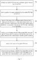


Classifications
-
- H—ELECTRICITY
- H04—ELECTRIC COMMUNICATION TECHNIQUE
- H04B—TRANSMISSION
- H04B10/00—Transmission systems employing electromagnetic waves other than radio-waves, e.g. infrared, visible or ultraviolet light, or employing corpuscular radiation, e.g. quantum communication
- H04B10/07—Arrangements for monitoring or testing transmission systems; Arrangements for fault measurement of transmission systems
- H04B10/075—Arrangements for monitoring or testing transmission systems; Arrangements for fault measurement of transmission systems using an in-service signal
- H04B10/079—Arrangements for monitoring or testing transmission systems; Arrangements for fault measurement of transmission systems using an in-service signal using measurements of the data signal
- H04B10/0791—Fault location on the transmission path
-
- H—ELECTRICITY
- H04—ELECTRIC COMMUNICATION TECHNIQUE
- H04B—TRANSMISSION
- H04B10/00—Transmission systems employing electromagnetic waves other than radio-waves, e.g. infrared, visible or ultraviolet light, or employing corpuscular radiation, e.g. quantum communication
- H04B10/03—Arrangements for fault recovery
- H04B10/032—Arrangements for fault recovery using working and protection systems
-
- H—ELECTRICITY
- H04—ELECTRIC COMMUNICATION TECHNIQUE
- H04B—TRANSMISSION
- H04B10/00—Transmission systems employing electromagnetic waves other than radio-waves, e.g. infrared, visible or ultraviolet light, or employing corpuscular radiation, e.g. quantum communication
- H04B10/03—Arrangements for fault recovery
- H04B10/038—Arrangements for fault recovery using bypasses
-
- H—ELECTRICITY
- H04—ELECTRIC COMMUNICATION TECHNIQUE
- H04B—TRANSMISSION
- H04B10/00—Transmission systems employing electromagnetic waves other than radio-waves, e.g. infrared, visible or ultraviolet light, or employing corpuscular radiation, e.g. quantum communication
- H04B10/07—Arrangements for monitoring or testing transmission systems; Arrangements for fault measurement of transmission systems
- H04B10/075—Arrangements for monitoring or testing transmission systems; Arrangements for fault measurement of transmission systems using an in-service signal
- H04B10/079—Arrangements for monitoring or testing transmission systems; Arrangements for fault measurement of transmission systems using an in-service signal using measurements of the data signal
-
- H—ELECTRICITY
- H04—ELECTRIC COMMUNICATION TECHNIQUE
- H04B—TRANSMISSION
- H04B10/00—Transmission systems employing electromagnetic waves other than radio-waves, e.g. infrared, visible or ultraviolet light, or employing corpuscular radiation, e.g. quantum communication
- H04B10/07—Arrangements for monitoring or testing transmission systems; Arrangements for fault measurement of transmission systems
- H04B10/075—Arrangements for monitoring or testing transmission systems; Arrangements for fault measurement of transmission systems using an in-service signal
- H04B10/079—Arrangements for monitoring or testing transmission systems; Arrangements for fault measurement of transmission systems using an in-service signal using measurements of the data signal
- H04B10/0795—Performance monitoring; Measurement of transmission parameters
Definitions
- the present disclosure relates to the field of communication, and in particular, to a method and a device for protecting service of an Optical Network Unit (ONU) in a Passive Optical Network (PON).
- ONU Optical Network Unit
- PON Passive Optical Network
- a typical PON system generally includes a central office end device (such as an Optical Line Terminal (OLT)), a customer end device (such as an ONU), and an Optical Distribution Network (ODN).
- OLT Optical Line Terminal
- ODN Optical Distribution Network
- PONs are mainly classified into Gigabit Passive Optical networks (GPONs), Ethernet Passive Optical Networks (EPONs), 10 Gigabit Passive Optical networks (lOG-PONs), and the like in terms of standard.
- GPONs Gigabit Passive Optical networks
- EPONs Ethernet Passive Optical Networks
- lOG-PONs 10 Gigabit Passive Optical networks
- an optical link protection technology may be introduced.
- the existing optical link protection technology for the PON mainly includes Type A, Type B, Type C, Type D, hand-in-hand protection and the like. These techniques are mainly directed towards an optical link protection between an ONU PON port and an OLT PON port. When a problem occurs in an optical link between the ONU PON port and the OLT PON port, a service cannot be normally acquired.
- An embodiment of the present disclosure provides a method for protecting service of an optical network unit (ONU), the method includes: configuring an uplink Passive Optical Network (PON) link and a redundant uplink Ethernet link for the ONU; detecting a quality of a signal transmitted by the uplink PON link of the ONU; detecting a link status of the redundant uplink Ethernet link in response to that the quality of the signal transmitted by the uplink PON link is determined to be lower than a preset quality threshold or in response to that the uplink PON link is detected to be interrupted; and switching a service bearing channel of the uplink PON link to the uplink Ethernet link in response to that the link status of the uplink Ethernet link is determined to satisfy a preset condition.
- PON Passive Optical Network
- An embodiment of the present disclosure further provides a method for protecting service of an optical network unit (ONU), the method includes: configuring an uplink Ethernet link and a redundant uplink Passive Optical Network (PON) link for the ONU; detecting a quality of a signal transmitted by the uplink Ethernet link of the ONU; detecting a link status of the redundant uplink PON link in response to that the quality of the signal transmitted by the uplink Ethernet link is determined to be lower than a preset quality threshold or in response to that the uplink Ethernet link is detected to be interrupted; and switching a service bearing channel of the uplink Ethernet link to the uplink PON link in response to that the link status of the uplink PON link is determined to satisfy a preset condition.
- PON optical network unit
- An embodiment of the present disclosure further provides a device for protecting service of an optical network unit (ONU), the device includes: a configuration unit configured to provide the ONU with an uplink Passive Optical Network (PON) link and a redundant uplink Ethernet link; a first detection unit configured to detect a quality of a signal transmitted by the uplink PON link of the ONU; a first determination unit configured to trigger a second detection unit in response to that the quality of the signal transmitted by the uplink PON link is determined to be lower than a preset quality threshold, or trigger the second detection unit in response to that the uplink PON link is detected to be interrupted; the second detection unit configured to detect a link status of the redundant uplink Ethernet link; a second determination unit configured to determine whether the link status of the uplink Ethernet link satisfies a preset condition, and trigger a first switching unit in response to that the link status of the uplink Ethernet link is determined to satisfy the preset condition; and the first switching unit configured to switch a service bearing channel of the uplink PON link to the uplink
- An embodiment of the present disclosure further provides a device for protecting service of an optical network unit (ONU), the device includes: a configuration unit configured to provide the ONU with an uplink Ethernet link and a redundant uplink Passive Optical Network (PON) link; a first detection unit configured to detect a quality of a signal transmitted by the uplink Ethernet link; a first determination unit configured to trigger a second detection unit in response to that the quality of the signal transmitted by the uplink Ethernet link is determined to be lower than a preset quality threshold, or trigger the second detection unit in response to that the uplink Ethernet link is detected to be interrupted; the second detection unit configured to detect a link status of the redundant uplink PON link; a second determination unit configured to determine whether the link status of the uplink PON link satisfies a preset condition, and trigger a first switching unit in response to that the link status of the uplink PON link is determined to satisfy the preset condition; and the first switching unit configured to switch a service bearing channel of the uplink Ethernet link to the uplink PON link.
- An embodiment of the present disclosure further provides a computer-readable storage medium storing a computer program, the computer program, when executed by a processor, cause the processor to implement the method for protecting service of the optical network unit in the embodiments of the present disclosure.
- Fig. 1 shows a topological diagram of a connection relationship of an existing optical network unit.
- a conventional Optical Network Unit (ONU) 10 is provided with only a PON port 13, the ONU 10 is connected to an Optical Distribution Network (ODN) 11 through the PON port 13, the ODN 11 is connected to a PON port 13 of an Optical Line Terminal (OLT) 12, and the ONU 10 acquires service only through an uplink PON link (a link from the PON port 13 of the ONU 10 to the PON port 13 of the OLT 12).
- ODN Optical Distribution Network
- ONT Optical Line Terminal
- Fig. 2 shows a topological diagram of a connection relationship of an optical network unit according to an embodiment of the present disclosure.
- the ONU 10 of the present embodiment is provided with a PON port 13 and an Ethernet (ETH) port 14.
- the ONU 10 is connected to an Optical Distribution Network (ODN) 11 through the PON port 13, the ODN 11 is connected to a PON port 13 of the OLT 12, and the ODN 11 provides an optical channel between the OLT 12 and the ONU 10.
- the ONU 10 is further connected to a service server 15 through the ETH port 14.
- ODN Optical Distribution Network
- the ONU 10 may be configured to acquire service from the OLT 12 via the PON port 13, i.e., an uplink PON link between the PON port 13 of the ONU 10 and the PON port 13 of the OLT 12 may be used as a service bearing channel.
- An uplink Ethernet link is between the ETH port 14 of the ONU 10 and the service server 15, and may be used as a redundant link for the uplink PON link.
- the ONU 10 may be set to temporarily not acquire service from the service server 15 through the ETH port 14.
- the ONU 10 may further be configured to acquire service from the service server 15 via the ETH port 14, i.e., the uplink Ethernet link between the ETH port 14 of the ONU 10 and the service server 15 may be used as a service bearing channel.
- the uplink PON link between the PON port 13 of the ONU 10 and the PON port 13 of the OLT 12 may be used as a redundant link for the uplink Ethernet link.
- the ONU 10 may be configured to temporarily not acquire service from the OLT 12 through the PON port 13.
- the following describes a specific process of the method for protecting service of the optical network unit according to the embodiment of the present disclosure with reference to a topology of connection relationship of the optical network unit.
- Fig. 5 is a schematic flowchart of a method for protecting service of an optical network unit according to an embodiment of the present disclosure. As shown in Fig. 5 , the method for protecting service of the optical network unit includes the following steps 501 to 506.
- an uplink Passive Optical Network (PON) link and a redundant uplink Ethernet link are configured for an Optical Network Unit (ONU).
- PON Passive Optical Network
- ONU Optical Network Unit
- the uplink Ethernet link between the ETH port 14 of the ONU 10 and the service server 15 is used as a redundant link for the uplink PON link between the PON port 13 of the ONU 10 and the PON port 13 of the OLT 12, and the ONU 10 is configured to temporarily not acquire service from the service server 15 through the ETH port 14.
- a quality of a signal transmitted by the uplink PON link of the ONU is detected.
- step 503 in response to that the quality of the signal transmitted by the uplink PON link is determined to be lower than a preset quality threshold or in response to that the uplink PON link is detected to be interrupted, a link status of the redundant uplink Ethernet link is detected.
- the quality of the signal transmitted by the uplink PON link being lower than the preset quality threshold may specifically include that a bit error rate of the uplink PON link is higher than a set value or a loss-of-frame (LOF) alarm is detected.
- the bit error rate being higher than the set value may be indicated by an alarm generated due to a bit error rate higher than 10 -3 .
- the step of detecting an interruption of the uplink PON link may specifically include detecting a loss-of-signal (LOS) alarm.
- LOS loss-of-signal
- a service bearing channel of the uplink PON link is switched to the uplink Ethernet link in response to that the link status of the uplink Ethernet link is determined to satisfy a preset condition.
- the ONU 10 When detecting that the uplink Ethernet link is connected, i.e., the ONU 10 is able to connect to the service server 15 via the uplink Ethernet link, the service bearing channel of the uplink PON link is switched to the uplink Ethernet link, and at this time, the ONU 10 no longer acquires service via the PON port 13, but instead acquires service via the ETH port 14.
- step 505 a link status of the uplink PON link is detected.
- the link status of the uplink PON link may be detected.
- the service bearing channel of the uplink Ethernet link is switched to the uplink PON link in response to the link status of the uplink PON link is determined to satisfy a preset condition.
- the service bearing channel of the uplink Ethernet link is switched to the uplink PON link, and the ONU 10 stops acquiring the service through the ETH port 14 and resumes acquiring the service through the PON port 13.
- the uplink Ethernet link is newly added to the ONU 10, and when it is detected that the uplink PON link of the ONU 10 has a problem and a service cannot be normally acquired from the uplink PON link, for example, when the quality of the signal transmitted by the uplink PON link is poor or when the uplink PON link is interrupted, if the redundant uplink Ethernet link satisfies a preset condition (e.g., transmission condition), the service bearing channel is switched to the uplink Ethernet link, and then when the uplink PON link reaches the preset condition again, the service bearing channel is switched back to the uplink PON link.
- a preset condition e.g., transmission condition
- Fig. 6 is a schematic flowchart of a method for protecting service of an optical network unit according to an embodiment of the present disclosure. As shown in Fig. 6 , the method for protecting service of the optical network unit includes the following steps 601 to 606.
- an uplink Ethernet link and a redundant uplink Passive Optical Network (PON) link are provided for an Optical Network Unit (ONU).
- PON Passive Optical Network
- the uplink PON link between the PON port 13 of the ONU 10 and the PON port 13 of the OLT 12 is used as a redundant link for the uplink Ethernet link between the ETH port 14 of the ONU 10 and the service server 15, and the ONU 10 is configured to temporarily not acquire service from the OLT 12 through the PON port 13.
- a quality of a signal transmitted by the uplink Ethernet link of the ONU is detected.
- step 603 in response to that the quality of the signal transmitted by the uplink Ethernet link is determined to be lower than a preset quality threshold value or in response to that the uplink Ethernet link is detected to be interrupted, a link status of the redundant uplink PON link is detected.
- the quality of the signal transmitted by the uplink Ethernet link being lower than the preset quality threshold may specifically include that a bit error rate of the uplink Ethernet link is higher than a set value or a loss-of-frame (LOF) alarm is detected.
- the bit error rate being higher than the set value may be indicated by an alarm generated due to a bit error rate higher than 10 -3 .
- the step of detecting an interruption of the uplink Ethernet link may specifically include detecting a loss-of-signal (LOS) alarm.
- LOS loss-of-signal
- a service bearing channel of the uplink Ethernet link is switched to the uplink PON link in response to that the link status of the uplink PON link is determined to satisfy a preset condition.
- the ONU 10 When detecting that the uplink PON link is connected, i.e., the ONU 10 is able to connect to the PON port 13 of the OLT 12 via the uplink PON link, the service bearing channel of the uplink Ethernet link is switched to the uplink PON link, and at this time, the ONU 10 no longer acquires service via the ETH port 14, but instead acquires service via the PON port 13.
- step 605 a link status of the uplink Ethernet link is detected.
- the link status of the uplink PON link may be detected.
- a service bearing channel of the uplink PON link is switched to the uplink Ethernet link in response to that the link status of the uplink Ethernet link is determined to satisfy a preset condition.
- the service bearing channel of the uplink PON link is switched to the uplink Ethernet link, and the ONU 10 stops acquiring the service through the PON port 13 and resumes acquiring the service through the ETH port 14.
- the uplink Ethernet link is newly added to the ONU 10, and when it is detected that the uplink Ethernet link of the ONU 10 has a problem and a service cannot be normally acquired from the uplink Ethernet link, for example, when the quality of the signal transmitted by the uplink Ethernet link is poor or the uplink Ethernet link is interrupted, if the redundant uplink PON link satisfies a preset condition (transmission condition), the service bearing channel is switched to the uplink PON link, and then when the uplink Ethernet link reaches the preset condition again, the service bearing channel is switched back to the uplink Ethernet link. Therefore, the problem that the service cannot be normally acquired when the uplink Ethernet link of the ONU 10 has a problem is solved.
- a preset condition transmission condition
- the method for protecting service of the ONU according to the embodiment of the present disclosure is further described below with reference to a case that the ONU 10 accesses different PON/Ethernet networks in practical application.
- Fig. 3 is a topological diagram of a connection relationship of an optical network unit according to an embodiment of the present disclosure.
- the ONU 10 of the present embodiment is provided with an Ethernet Passive Optical Network (EPON) port 16 and a Gigabit Ethernet (GE) port 17.
- the ONU 10 is connected to an Optical Distribution Network (ODN) 11 via the EPON port 16, the ODN 11 is connected to an EPON port 16 of an Optical Line Terminal (OLT) 12, and the ODN 11 provides an optical channel between the OLT 12 and the ONU 10.
- the ONU 10 is further connected to a service server 15 through the GE port 17.
- the ONU 10 may be configured to acquire service from the OLT 12 via the EPON port 16, i.e., an uplink EPON link between the EPON port 16 of the ONU 10 and the EPON port 16 of the OLT 12 may serve as a service bearing channel.
- An uplink GE link between the GE port 17 of the ONU 10 and the service server 15 may be used as a redundant link for the uplink EPON link.
- the ONU 10 may be set to temporarily not acquire service from the service server 15 through the GE port 17.
- Fig. 7 is a schematic flowchart of a method for protecting service of an optical network unit according to an embodiment of the present disclosure. As shown in Fig. 7 , the method for protecting service of the optical network unit in the embodiment includes the following steps S701 to S706.
- an uplink EPON link and a redundant uplink GE link are provided for an Optical Network Unit (ONU).
- ONU Optical Network Unit
- the uplink GE link between the GE port 17 of the ONU 10 and the service server 15 is used as a redundant link for the uplink EPON link between the EPON port 16 of the ONU 10 and the EPON port 16 of the OLT 12, and the ONU 10 is configured to temporarily not acquire service from the service server 15 via the GE port 17.
- a quality of a signal transmitted by the uplink EPON link (i.e., from the ONU 10 to the OLT 12) of the ONU 10 is detected.
- a link status of the redundant uplink GE link (i.e., from the GE port 17 to the service server 15) is detected in response to that an alarm generated due to a bit error rate higher than 10 -3 , a loss-of-frame (LOF) alarm, or a loss-of-signal (LOS) alarm is detected for the uplink EPON link.
- LEF loss-of-frame
- LOS loss-of-signal
- step S704 in response to that the uplink GE link is detected to be connected, i.e., the ONU 10 is able to connect to the service server 15 via the uplink GE link, a service bearing channel of the uplink EPON link is switched to the uplink GE link, and the ONU 10 no longer acquires service via the EPON port 16, but instead acquires service via the GE port 17.
- step S705 after a preset time duration ⁇ o elapsing from a time at which the service bearing channel of the uplink PON link is switched to the uplink Ethernet link, a link status of the uplink PON link is detected.
- step S706 in response to that the uplink EPON link is detected to be connected and the alarm indicating the bit error rate higher than 10 -3 disappears, a service bearing channel of the uplink GE link is switched to the uplink EPON link, the ONU 10 stops acquiring the service through the GE port 17 and resumes acquiring the service through the EPON port 16.
- the uplink GE link is newly added to the ONU 10, and when it is detected that the uplink EPON link of the ONU 10 has a problem and a service cannot be normally acquired from the uplink EPON link, for example, when the quality of the signal transmitted by the uplink EPON link is poor or the uplink EPON link is interrupted, if the redundant uplink GE link satisfies a preset condition (transmission condition), the service bearing channel is switched to the uplink GE link, and then when the uplink EPON link reaches the preset condition again, the service bearing channel is switched back to the uplink EPON link.
- a preset condition transmission condition
- Fig. 4 is a topological diagram of a connection relationship of an optical network unit according to an embodiment of the present disclosure.
- the ONU 10 of the present embodiment is provided with a Gigabit Passive Optical Network (GPON) port 18 and a 10G Ethernet (10 GE) port 19.
- the ONU 10 is connected to an Optical Distribution Network (ODN) 11 via the GPON port 18, the ODN 11 is connected to a GPON port 18 of an Optical Line Terminal (OLT) 12, and the ODN 11 provides an optical channel between the OLT 12 and the ONU 10.
- ODN Optical Distribution Network
- ONT Optical Line Terminal
- the ONU 10 is further connected to a service server 15 through the 10GE port 19.
- the ONU10 may be configured to acquire service from the service server 15 via the 10GE port 19, i.e., an uplink 10GE link between the 10GE port 19 of the ONU10 to the service server 15 may be used as a service bearing channel.
- An uplink GPON link between the GPON port 18 of the ONU10 and the GPON port 18 of the OLT 12 may serve as a redundant link for the uplink 10GE link.
- the ONU10 may be set to temporarily not acquire service from the OLT 12 through the GPON port 18.
- Fig. 8 shows a schematic flowchart of a method for protecting service of an optical network unit according to an embodiment of the present disclosure. As shown in Fig. 8 , the method for protecting service of the optical network unit in the embodiment includes the following steps S801 to S806.
- an uplink 10GE link and a redundant uplink GPON link are provided for an Optical Network Unit (ONU).
- ONU Optical Network Unit
- the uplink GPON link between the GPON port 18 of the ONU 10 and the GPON port 18 of the OLT 12 is used as a redundant link for the uplink 10GE link between the 10GE port 19 of the ONU 10 to the service server 15, and the ONU 10 is set to temporarily not acquire service from the OLT 12 through the GPON port 18.
- a quality of a signal transmitted by the uplink 10GE link (i.e., from the 10GE port 19 to the service server 15) of the ONU 10 is detected.
- a link status of the redundant uplink GPON link i.e., from the GPON port 18 of the ONU 10 to the GPON port 18 of the OLT 12
- an alarm generated due to a bit error rate higher than 10 -3 a loss-of-frame (LOF) alarm, or a loss-of-signal (LOS) alarm is detected for the uplink 10GE link.
- LEF loss-of-frame
- LOS loss-of-signal
- step S804 in response to that the uplink GPON link is detected to be connected, i.e., the ONU 10 is able to connect to the OLT 12 via the uplink GPON link, a service bearing channel of the uplink 10GE link is switched to the uplink GPON link, and the ONU 10 no longer acquires service via the 10GE port 19, but instead acquires traffic via the GPON port 18.
- step S805 after a preset time duration ⁇ o elapsing from a time at which the service bearing channel of the uplink 10GE link is switched to the uplink GPON link, a link status of the uplink 10GE link is detected.
- step S806 in response to that the uplink 10GE link is detected to be connected and the alarm indicating the bit error rate higher than 10 -3 disappears, a service bearing channel of the uplink GPON link is switched to the uplink 10GE link, the ONU 10 stops acquiring the service through the GPON port 18, and resumes acquiring the service through the 10GE port 19.
- the uplink 10GE link is newly added to the ONU, and when it is detected that the uplink 10GE link of the ONU 10 has a problem and a service cannot be normally obtained from the uplink 10GE link, for example, when the quality of the signal transmitted by the uplink 10GE link is poor or the uplink 10GE link is interrupted, if the redundant uplink GPON link satisfies a preset condition (transmission condition), the service bearing channel is switched to the uplink GPON link, and then when the uplink 10GE link reaches the preset condition again, the service bearing channel is switched back to the uplink 10GE link.
- a preset condition transmission condition
- the PON is GPON or EPON
- the Ethernet is GE or 10GE
- the PON may be a 10G-PON
- the Ethernet may be a Fast Ethernet (FE).
- Fig. 9 is a schematic structural diagram of a device for protecting service of an optical network unit according to an embodiment of the present disclosure.
- the device for protecting service of the optical network unit in the embodiment includes: a configuration unit 98 configured to provide an Optical Network Unit (ONU) with an uplink Passive Optical Network (PON) link and a redundant uplink Ethernet link; a first detection unit 90 configured to detect a quality of a signal transmitted by the uplink PON link of the ONU; a first determination unit 91 configured to trigger a second detection unit 92 in response to that the quality of the signal transmitted by the uplink PON link is determined to be lower than a preset quality threshold; the second detection unit 92 configured to detect a link status of the redundant uplink Ethernet link; a second determination unit 93 configured to determine whether the link status of the uplink Ethernet link satisfies a preset condition, and trigger a first switching unit 94 in response to that the link status of the uplink Ethernet link is determined to satisfy the preset condition
- ONU Opti
- the device for protecting service of the optical network unit may further include a third detection unit 95, a third determination unit 96, and a second switching unit 97.
- the third detection unit 95 is configured to detect a link status of the uplink PON link after switching the service bearing channel of the uplink PON link to the uplink Ethernet link.
- the third determination unit 96 is configured to determine whether the link status of the uplink PON link satisfies a preset condition, and trigger the second switching unit 97 in response to that the link status of the uplink PON link is determined to satisfy the preset condition.
- the second switching unit 97 is configured to switch a service bearing channel of the uplink Ethernet link to the uplink PON link.
- the quality of the signal transmitted by the uplink PON link being lower than the preset quality threshold includes: a bit error rate of the uplink PON link is higher than a set value or a loss-of-frame (LOF) alarm is detected.
- LEF loss-of-frame
- the uplink Ethernet link is newly added to the ONU, and when it is detected that the quality of the signal transmitted by the uplink PON link of the ONU is lower than the preset quality threshold, if the redundant uplink Ethernet link satisfies the preset condition (transmission condition), the service bearing channel is switched to the uplink Ethernet link, and then when the uplink PON link reaches the preset condition again, the service bearing channel is switched back to the uplink PON link.
- the preset condition transmission condition
- each unit in the device for protecting service of the optical network unit shown in Fig. 9 can be understood by referring to the related description of the foregoing method for protecting service of the optical network unit.
- the functions of each unit in the device for protecting service of the optical network unit shown in Fig. 9 may be implemented by a program running on a processor, or may be implemented by a specific logic circuit.
- An embodiment of the present disclosure further provides a device for protecting an optical network unit, as shown in Fig. 10 , the device for protecting service of the optical network unit in the embodiment includes: a configuration unit 108 configured to provide an Optical Network Unit (ONU) with an uplink Passive Optical Network (PON) link and a redundant uplink Ethernet link; a first detection unit 100 configured to detect a quality of a signal transmitted by the uplink PON link of the ONU; a first determination unit 101 configured to determine whether the uplink PON link is interrupted, and trigger a second detection unit 102 in response to that the uplink PON link is detected to be interrupted; the second detection unit 102 configured to detect a link status of the redundant uplink Ethernet link; a second determination unit 103 configured to determine whether the link status of the uplink Ethernet link satisfies a preset condition, and trigger a first switching unit 104 in response to that the link status of the uplink Ethernet link is determined to satisfy the preset condition; and the first switching unit 104 configured to switch a service bearing
- the device for protecting service of the optical network unit may further include a third detection unit 105, a third determination unit 106, and a second switching unit 107.
- the third detection unit 105 is configured to detect a link status of the uplink PON link after switching the service bearing channel of the uplink PON link to the uplink Ethernet link.
- the third determination unit 106 is configured to determine whether the link status of the uplink PON link satisfies a preset condition, and trigger the second switching unit 107 in response to that the link status of the uplink PON link is determined to satisfy the preset condition.
- the second switching unit 107 is configured to switch a service bearing channel of the uplink Ethernet link to the uplink PON link.
- determining that the uplink PON link is interrupted includes: a loss-of-signal (LOS) alarm is detected.
- LOS loss-of-signal
- the uplink Ethernet link is newly added to the ONU, and when it is detected that the uplink PON link of the ONU is interrupted and a service cannot be normally acquired from the uplink PON link, if the redundant uplink Ethernet link satisfies a preset condition (transmission condition), the service bearing channel is switched to the uplink Ethernet link, and then when the uplink PON link reaches the preset condition again, the service bearing channel is switched back to the uplink PON link.
- a preset condition transmission condition
- each unit in the device for protecting service of the optical network unit shown in Fig. 10 can be understood by referring to the related description of the foregoing method for protecting service of the optical network unit.
- the functions of each unit in the device for protecting service of the optical network unit shown in Fig. 10 may be implemented by a program running on a processor, or may be implemented by a specific logic circuit.
- An embodiment of the present disclosure further provides a device for protecting service of an optical network unit, as shown in Fig. 11 , the device for protecting service of the optical network unit in the embodiment includes: a configuration unit 118 configured to provide an Optical Network Unit (ONU) with an uplink Ethernet link and a redundant uplink Passive Optical Network (PON) link; a first detection unit 110 configured to detect a quality of a signal transmitted by the uplink Ethernet link of the ONU; a first determination unit 111 configured to trigger a second detection unit 112 in response to that the quality of the signal transmitted by the uplink Ethernet link is determined to be lower than a preset quality threshold; the second detection unit 112 configured to detect a link status of the redundant uplink PON link; a second determination unit 113 configured to determine whether the link status of the uplink PON link satisfies a preset condition, and trigger a first switching unit 114 in response to that the link status of the uplink PON link is determined to satisfy the preset condition; and the first switching unit 114 configured
- the device for protecting service of the optical network unit may further include a third detection unit 115, a third determination unit 116, and a second switching unit 117.
- the third detection unit 115 is configured to detect a link status of the uplink Ethernet link after switching the service bearing channel of the uplink Ethernet link to the uplink PON link.
- the third determination unit 116 is configured to determine whether the link status of the uplink Ethernet link satisfies a preset condition, and trigger the second switching unit 117 in response to that the link status of the uplink Ethernet link is determined to satisfy the preset condition.
- the second switching unit 117 is configured to switch a service bearing channel of the uplink PON link to the uplink Ethernet link.
- the quality of the signal transmitted by the uplink Ethernet link being lower than the preset quality threshold includes: a bit error rate of the uplink Ethernet link is higher than a set value or a loss-of-frame (LOF) alarm is detected.
- LEF loss-of-frame
- the uplink Ethernet link is newly added to the ONU, and when it is detected that the quality of the signal transmitted by the uplink Ethernet link of the ONU is lower than the preset quality threshold, if the redundant uplink PON link satisfies the preset condition (transmission condition), the service bearing channel is switched to the uplink PON link, and then when the uplink Ethernet link reaches the preset condition again, the service bearing channel is switched back to the uplink Ethernet link.
- the preset condition transmission condition
- each unit in the device for protecting service of the optical network unit shown in Fig. 11 can be understood by referring to the related description of the foregoing method for protecting service of the optical network unit.
- the functions of each unit in the device for protecting service of the optical network unit shown in Fig. 11 may be implemented by a program running on a processor, or may be implemented by a specific logic circuit.
- An embodiment of the present disclosure further provides a device for protecting service of an optical network unit, as shown in Fig. 12 , the device for protecting service of the optical network unit in the embodiment includes: a configuration unit 128 configured to provide an Optical Network Unit (ONU) with an uplink Ethernet link and a redundant uplink Passive Optical Network (PON) link; a first detection unit 120 configured to detect a quality of a signal transmitted by the uplink Ethernet link of the ONU; a first determination unit 121 configured to determine whether the uplink Ethernet link is interrupted, and trigger a second detection unit 122 in response to that the uplink Ethernet link is detected to be interrupted; the second detection unit 122 configured to detect a link status of the redundant uplink PON link; a second determination unit 123 configured to determine whether the link status of the uplink PON link satisfies a preset condition, and trigger a first switching unit 124 in response to that the link status of the uplink PON link is determined to satisfy the preset condition; and the first switching unit 124 configured to switch
- the device for protecting service of the optical network unit may further include a third detection unit 125, a third determination unit 126, and a second switching unit 127.
- the third detection unit 125 is configured to detect a link status of the uplink Ethernet link after switching the service bearing channel of the uplink Ethernet link to the uplink PON link.
- the third determination unit 126 is configured to determine whether the link status of the uplink Ethernet link satisfies a preset condition, and trigger the second switching unit 127 in response to that the link status of the uplink Ethernet link is determined to satisfy the preset condition.
- the second switching unit 127 is configured to switch a service bearing channel of the uplink PON link to the uplink Ethernet link.
- determining that the uplink Ethernet link is interrupted includes: a loss-of-signal (LOS) alarm is detected.
- LOS loss-of-signal
- the uplink Ethernet link is newly added to the ONU, and when it is detected that the uplink Ethernet link of the ONU is interrupted and a service cannot be normally acquired from the uplink Ethernet link, if the redundant uplink PON link satisfies the preset condition (transmission condition), the service bearing channel is switched to the uplink PON link, and then when the uplink Ethernet link reaches the preset condition again, the service bearing channel is switched back to the uplink Ethernet link.
- the preset condition transmission condition
- each unit in the device for protecting service of the optical network unit shown in Fig. 12 can be understood by referring to the related description of the foregoing method for protecting service of the optical network unit.
- the functions of each unit in the device for protecting service of the optical network unit shown in Fig. 12 may be implemented by a program running on a processor, or may be implemented by a specific logic circuit.
- the functions implemented by the foregoing device for protecting service of the optical network unit may be implemented by a central processing unit (CPU), a microprocessor unit (MPU), a digital signal processor (DSP), or a field programmable gate array (FPGA) located in the device for protecting service of the optical network unit.
- CPU central processing unit
- MPU microprocessor unit
- DSP digital signal processor
- FPGA field programmable gate array
- the device for protecting service of the optical network unit in the embodiment of the present disclosure may also be stored in a computer-readable storage medium if it is implemented in the form of a software function module and sold or used as an independent product.
- a software product which may be stored in a storage medium and include several executable instructions to enable a computer device (e.g., a personal computer, a server, or a network device, etc.) to execute all or a part of the method for protecting service of the optical network unit in the embodiments of the present disclosure.
- the storage medium may include a USB disk, a removable hard disk, a read only memory (ROM), a magnetic disk, an optical disk, or other storage media capable of storing program codes.
- ROM read only memory
- the storage medium may include a USB disk, a removable hard disk, a read only memory (ROM), a magnetic disk, an optical disk, or other storage media capable of storing program codes.
- an embodiment of the present disclosure further provides a computer-readable storage medium storing a computer program, the computer program, when executed by a processor, cause the processor to implement the method for protecting service of the optical network unit in the embodiments of the present disclosure.
- an Ethernet port and an Ethernet link are newly added to the ONU, and the Ethernet link and the PON link are redundant for each other, and one of the Ethernet link and the PON link is set as a service bearing link and the other is set as a standby redundant link, thereby ensuring reliability of data transmission.
- the redundant link when it is detected that a signal interruption occurs in the service bearing link or a quality of a signal transmitted by the service bearing link is lower than a preset quality threshold, and a link status of the redundant link satisfies a preset condition, the redundant link is used as a new service bearing link, and when the original service bearing link reaches the preset condition again, the original service bearing link is used again. Therefore, the problem that the service cannot be normally acquired when the service bearing link of the ONU has a problem is solved.
Landscapes
- Physics & Mathematics (AREA)
- Electromagnetism (AREA)
- Engineering & Computer Science (AREA)
- Computer Networks & Wireless Communication (AREA)
- Signal Processing (AREA)
- Small-Scale Networks (AREA)
Abstract
Description
- The present disclosure relates to the field of communication, and in particular, to a method and a device for protecting service of an Optical Network Unit (ONU) in a Passive Optical Network (PON).
- PON technology is an important technology for an optical fiber access network, and is a mainstream technology for implementing fiber to the x (FTTx). A typical PON system generally includes a central office end device (such as an Optical Line Terminal (OLT)), a customer end device (such as an ONU), and an Optical Distribution Network (ODN).
- PONs are mainly classified into Gigabit Passive Optical networks (GPONs), Ethernet Passive Optical Networks (EPONs), 10 Gigabit Passive Optical networks (lOG-PONs), and the like in terms of standard. In order to improve robustness and reliability of service provided by the PON, an optical link protection technology may be introduced. The existing optical link protection technology for the PON mainly includes Type A, Type B, Type C, Type D, hand-in-hand protection and the like. These techniques are mainly directed towards an optical link protection between an ONU PON port and an OLT PON port. When a problem occurs in an optical link between the ONU PON port and the OLT PON port, a service cannot be normally acquired.
- An embodiment of the present disclosure provides a method for protecting service of an optical network unit (ONU), the method includes: configuring an uplink Passive Optical Network (PON) link and a redundant uplink Ethernet link for the ONU; detecting a quality of a signal transmitted by the uplink PON link of the ONU; detecting a link status of the redundant uplink Ethernet link in response to that the quality of the signal transmitted by the uplink PON link is determined to be lower than a preset quality threshold or in response to that the uplink PON link is detected to be interrupted; and switching a service bearing channel of the uplink PON link to the uplink Ethernet link in response to that the link status of the uplink Ethernet link is determined to satisfy a preset condition.
- An embodiment of the present disclosure further provides a method for protecting service of an optical network unit (ONU), the method includes: configuring an uplink Ethernet link and a redundant uplink Passive Optical Network (PON) link for the ONU; detecting a quality of a signal transmitted by the uplink Ethernet link of the ONU; detecting a link status of the redundant uplink PON link in response to that the quality of the signal transmitted by the uplink Ethernet link is determined to be lower than a preset quality threshold or in response to that the uplink Ethernet link is detected to be interrupted; and switching a service bearing channel of the uplink Ethernet link to the uplink PON link in response to that the link status of the uplink PON link is determined to satisfy a preset condition.
- An embodiment of the present disclosure further provides a device for protecting service of an optical network unit (ONU), the device includes: a configuration unit configured to provide the ONU with an uplink Passive Optical Network (PON) link and a redundant uplink Ethernet link; a first detection unit configured to detect a quality of a signal transmitted by the uplink PON link of the ONU; a first determination unit configured to trigger a second detection unit in response to that the quality of the signal transmitted by the uplink PON link is determined to be lower than a preset quality threshold, or trigger the second detection unit in response to that the uplink PON link is detected to be interrupted; the second detection unit configured to detect a link status of the redundant uplink Ethernet link; a second determination unit configured to determine whether the link status of the uplink Ethernet link satisfies a preset condition, and trigger a first switching unit in response to that the link status of the uplink Ethernet link is determined to satisfy the preset condition; and the first switching unit configured to switch a service bearing channel of the uplink PON link to the uplink Ethernet link.
- An embodiment of the present disclosure further provides a device for protecting service of an optical network unit (ONU), the device includes: a configuration unit configured to provide the ONU with an uplink Ethernet link and a redundant uplink Passive Optical Network (PON) link; a first detection unit configured to detect a quality of a signal transmitted by the uplink Ethernet link; a first determination unit configured to trigger a second detection unit in response to that the quality of the signal transmitted by the uplink Ethernet link is determined to be lower than a preset quality threshold, or trigger the second detection unit in response to that the uplink Ethernet link is detected to be interrupted; the second detection unit configured to detect a link status of the redundant uplink PON link; a second determination unit configured to determine whether the link status of the uplink PON link satisfies a preset condition, and trigger a first switching unit in response to that the link status of the uplink PON link is determined to satisfy the preset condition; and the first switching unit configured to switch a service bearing channel of the uplink Ethernet link to the uplink PON link.
- An embodiment of the present disclosure further provides a computer-readable storage medium storing a computer program, the computer program, when executed by a processor, cause the processor to implement the method for protecting service of the optical network unit in the embodiments of the present disclosure.
-
-
Fig. 1 is a topological diagram of a connection relationship of an existing optical network unit; -
Fig. 2 is a topological diagram of a connection relationship of an optical network unit according to an embodiment of the present disclosure; -
Fig. 3 is a topological diagram of a connection relationship of an optical network unit according to an embodiment of the present disclosure; -
Fig. 4 is a topological diagram of a connection relationship of an optical network unit according to an embodiment of the present disclosure; -
Fig. 5 is a schematic flowchart of a method for protecting service of an optical network unit according to an embodiment of the present disclosure; -
Fig. 6 is a schematic flowchart of a method for protecting service of an optical network unit according to an embodiment of the present disclosure; -
Fig. 7 is a schematic flowchart of a method for protecting service of an optical network unit according to an embodiment of the present disclosure; -
Fig. 8 is a schematic flowchart of a method for protecting service of an optical network unit according to an embodiment of the present disclosure; -
Fig. 9 is a schematic structural diagram of a device for protecting service of an optical network unit according to an embodiment of the present disclosure; -
Fig. 10 is a schematic structural diagram of a device for protecting service of an optical network unit according to an embodiment of the present disclosure; -
Fig. 11 is a schematic structural diagram of a device for protecting service of an optical network unit according to an embodiment of the present disclosure; and -
Fig. 12 is a schematic structural diagram of a device for protecting service of an optical network unit according to an embodiment of the present disclosure. - In order to explain features of the present disclosure in more detail, embodiments of the present disclosure are explained in detail below with reference to the accompanying drawings, which are for reference and not intended to limit the present disclosure.
-
Fig. 1 shows a topological diagram of a connection relationship of an existing optical network unit. As shown inFig. 1 , a conventional Optical Network Unit (ONU) 10 is provided with only aPON port 13, the ONU 10 is connected to an Optical Distribution Network (ODN) 11 through thePON port 13, the ODN 11 is connected to aPON port 13 of an Optical Line Terminal (OLT) 12, and the ONU 10 acquires service only through an uplink PON link (a link from thePON port 13 of the ONU 10 to thePON port 13 of the OLT 12). -
Fig. 2 shows a topological diagram of a connection relationship of an optical network unit according to an embodiment of the present disclosure. As shown inFig. 2 , the ONU 10 of the present embodiment is provided with aPON port 13 and an Ethernet (ETH)port 14. The ONU 10 is connected to an Optical Distribution Network (ODN) 11 through thePON port 13, the ODN 11 is connected to aPON port 13 of theOLT 12, and the ODN 11 provides an optical channel between theOLT 12 and the ONU 10. In addition, the ONU 10 is further connected to aservice server 15 through theETH port 14. - The ONU 10 may be configured to acquire service from the OLT 12 via the
PON port 13, i.e., an uplink PON link between thePON port 13 of the ONU 10 and thePON port 13 of the OLT 12 may be used as a service bearing channel. An uplink Ethernet link is between theETH port 14 of the ONU 10 and theservice server 15, and may be used as a redundant link for the uplink PON link. The ONU 10 may be set to temporarily not acquire service from theservice server 15 through the ETHport 14. - The ONU 10 may further be configured to acquire service from the
service server 15 via theETH port 14, i.e., the uplink Ethernet link between theETH port 14 of the ONU 10 and theservice server 15 may be used as a service bearing channel. The uplink PON link between thePON port 13 of the ONU 10 and thePON port 13 of the OLT 12 may be used as a redundant link for the uplink Ethernet link. The ONU 10 may be configured to temporarily not acquire service from the OLT 12 through thePON port 13. - The following describes a specific process of the method for protecting service of the optical network unit according to the embodiment of the present disclosure with reference to a topology of connection relationship of the optical network unit.
-
Fig. 5 is a schematic flowchart of a method for protecting service of an optical network unit according to an embodiment of the present disclosure. As shown inFig. 5 , the method for protecting service of the optical network unit includes thefollowing steps 501 to 506. - At
step 501, an uplink Passive Optical Network (PON) link and a redundant uplink Ethernet link are configured for an Optical Network Unit (ONU). - As shown in
Fig. 2 , the uplink Ethernet link between theETH port 14 of the ONU 10 and theservice server 15 is used as a redundant link for the uplink PON link between thePON port 13 of the ONU 10 and thePON port 13 of theOLT 12, and the ONU 10 is configured to temporarily not acquire service from theservice server 15 through theETH port 14. - At
step 502, a quality of a signal transmitted by the uplink PON link of the ONU is detected. - That is, after the connection relationship of the ONU 10 shown in
Fig. 2 is configured, a detection for the quality of the signal transmitted by the uplink PON link is started. - At
step 503, in response to that the quality of the signal transmitted by the uplink PON link is determined to be lower than a preset quality threshold or in response to that the uplink PON link is detected to be interrupted, a link status of the redundant uplink Ethernet link is detected. - In the embodiment, the quality of the signal transmitted by the uplink PON link being lower than the preset quality threshold may specifically include that a bit error rate of the uplink PON link is higher than a set value or a loss-of-frame (LOF) alarm is detected. The bit error rate being higher than the set value may be indicated by an alarm generated due to a bit error rate higher than 10-3.
- In the embodiment, the step of detecting an interruption of the uplink PON link may specifically include detecting a loss-of-signal (LOS) alarm.
- At
step 504, a service bearing channel of the uplink PON link is switched to the uplink Ethernet link in response to that the link status of the uplink Ethernet link is determined to satisfy a preset condition. - When detecting that the uplink Ethernet link is connected, i.e., the ONU 10 is able to connect to the
service server 15 via the uplink Ethernet link, the service bearing channel of the uplink PON link is switched to the uplink Ethernet link, and at this time, the ONU 10 no longer acquires service via thePON port 13, but instead acquires service via theETH port 14. - At
step 505, a link status of the uplink PON link is detected. - For example, after a preset time duration το elapsing from a time at which the service bearing channel of the uplink PON link is switched to the uplink Ethernet link, the link status of the uplink PON link may be detected.
- At
step 506, the service bearing channel of the uplink Ethernet link is switched to the uplink PON link in response to the link status of the uplink PON link is determined to satisfy a preset condition. - When detecting that the uplink PON link is connected and the alarm indicating the bit error rate higher than 10-3 disappears, the service bearing channel of the uplink Ethernet link is switched to the uplink PON link, and the ONU 10 stops acquiring the service through the
ETH port 14 and resumes acquiring the service through thePON port 13. - In the embodiment, the uplink Ethernet link is newly added to the ONU 10, and when it is detected that the uplink PON link of the ONU 10 has a problem and a service cannot be normally acquired from the uplink PON link, for example, when the quality of the signal transmitted by the uplink PON link is poor or when the uplink PON link is interrupted, if the redundant uplink Ethernet link satisfies a preset condition (e.g., transmission condition), the service bearing channel is switched to the uplink Ethernet link, and then when the uplink PON link reaches the preset condition again, the service bearing channel is switched back to the uplink PON link. Thus, the problem that the service cannot be normally acquired when the uplink PON link of the ONU 10 has a problem is solved.
-
Fig. 6 is a schematic flowchart of a method for protecting service of an optical network unit according to an embodiment of the present disclosure. As shown inFig. 6 , the method for protecting service of the optical network unit includes thefollowing steps 601 to 606. - At
step 601, an uplink Ethernet link and a redundant uplink Passive Optical Network (PON) link are provided for an Optical Network Unit (ONU). - As shown in
Fig. 2 , the uplink PON link between thePON port 13 of theONU 10 and thePON port 13 of theOLT 12 is used as a redundant link for the uplink Ethernet link between theETH port 14 of theONU 10 and theservice server 15, and theONU 10 is configured to temporarily not acquire service from theOLT 12 through thePON port 13. - At
step 602, a quality of a signal transmitted by the uplink Ethernet link of the ONU is detected. - That is, after a connection relationship of the
ONU 10 shown inFig. 2 is configured, a detection for the quality of the signal transmitted by the uplink Ethernet link is started. - At
step 603, in response to that the quality of the signal transmitted by the uplink Ethernet link is determined to be lower than a preset quality threshold value or in response to that the uplink Ethernet link is detected to be interrupted, a link status of the redundant uplink PON link is detected. - In the embodiment, the quality of the signal transmitted by the uplink Ethernet link being lower than the preset quality threshold may specifically include that a bit error rate of the uplink Ethernet link is higher than a set value or a loss-of-frame (LOF) alarm is detected. The bit error rate being higher than the set value may be indicated by an alarm generated due to a bit error rate higher than 10-3.
- In the embodiment, the step of detecting an interruption of the uplink Ethernet link may specifically include detecting a loss-of-signal (LOS) alarm.
- At
step 604, a service bearing channel of the uplink Ethernet link is switched to the uplink PON link in response to that the link status of the uplink PON link is determined to satisfy a preset condition. - When detecting that the uplink PON link is connected, i.e., the
ONU 10 is able to connect to thePON port 13 of theOLT 12 via the uplink PON link, the service bearing channel of the uplink Ethernet link is switched to the uplink PON link, and at this time, theONU 10 no longer acquires service via theETH port 14, but instead acquires service via thePON port 13. - At
step 605, a link status of the uplink Ethernet link is detected. - For example, after a preset time duration το elapsing from a time at which the service bearing channel of the uplink Ethernet link is switched to the uplink PON link, the link status of the uplink PON link may be detected.
- At
step 606, a service bearing channel of the uplink PON link is switched to the uplink Ethernet link in response to that the link status of the uplink Ethernet link is determined to satisfy a preset condition. - When detecting that the uplink Ethernet link is connected and the alarm indicating the bit error rate higher than 10-3 disappears, the service bearing channel of the uplink PON link is switched to the uplink Ethernet link, and the
ONU 10 stops acquiring the service through thePON port 13 and resumes acquiring the service through theETH port 14. - In the embodiment, the uplink Ethernet link is newly added to the
ONU 10, and when it is detected that the uplink Ethernet link of theONU 10 has a problem and a service cannot be normally acquired from the uplink Ethernet link, for example, when the quality of the signal transmitted by the uplink Ethernet link is poor or the uplink Ethernet link is interrupted, if the redundant uplink PON link satisfies a preset condition (transmission condition), the service bearing channel is switched to the uplink PON link, and then when the uplink Ethernet link reaches the preset condition again, the service bearing channel is switched back to the uplink Ethernet link. Therefore, the problem that the service cannot be normally acquired when the uplink Ethernet link of theONU 10 has a problem is solved. - The method for protecting service of the ONU according to the embodiment of the present disclosure is further described below with reference to a case that the
ONU 10 accesses different PON/Ethernet networks in practical application. -
Fig. 3 is a topological diagram of a connection relationship of an optical network unit according to an embodiment of the present disclosure. As shown inFig. 3 , theONU 10 of the present embodiment is provided with an Ethernet Passive Optical Network (EPON)port 16 and a Gigabit Ethernet (GE)port 17. TheONU 10 is connected to an Optical Distribution Network (ODN) 11 via theEPON port 16, theODN 11 is connected to anEPON port 16 of an Optical Line Terminal (OLT) 12, and theODN 11 provides an optical channel between theOLT 12 and theONU 10. In addition, theONU 10 is further connected to aservice server 15 through theGE port 17. - The
ONU 10 may be configured to acquire service from theOLT 12 via theEPON port 16, i.e., an uplink EPON link between theEPON port 16 of theONU 10 and theEPON port 16 of theOLT 12 may serve as a service bearing channel. An uplink GE link between theGE port 17 of theONU 10 and theservice server 15 may be used as a redundant link for the uplink EPON link. TheONU 10 may be set to temporarily not acquire service from theservice server 15 through theGE port 17. - The method for protecting service of the optical network unit provided by the embodiment of the present disclosure is described in detail below with reference to a topology of connection relationship of the optical network unit.
-
Fig. 7 is a schematic flowchart of a method for protecting service of an optical network unit according to an embodiment of the present disclosure. As shown inFig. 7 , the method for protecting service of the optical network unit in the embodiment includes the following steps S701 to S706. - At step S701, an uplink EPON link and a redundant uplink GE link are provided for an Optical Network Unit (ONU).
- As shown in
Fig. 3 , the uplink GE link between theGE port 17 of theONU 10 and theservice server 15 is used as a redundant link for the uplink EPON link between theEPON port 16 of theONU 10 and theEPON port 16 of theOLT 12, and theONU 10 is configured to temporarily not acquire service from theservice server 15 via theGE port 17. - At step S702, a quality of a signal transmitted by the uplink EPON link (i.e., from the
ONU 10 to the OLT 12) of theONU 10 is detected. - That is, after the connection relationship of the
ONU 10 shown inFig. 3 is configured, a detection of the quality of the signal transmitted by the uplink EPON link is started. - At step S703, a link status of the redundant uplink GE link (i.e., from the
GE port 17 to the service server 15) is detected in response to that an alarm generated due to a bit error rate higher than 10-3, a loss-of-frame (LOF) alarm, or a loss-of-signal (LOS) alarm is detected for the uplink EPON link. - At step S704, in response to that the uplink GE link is detected to be connected, i.e., the
ONU 10 is able to connect to theservice server 15 via the uplink GE link, a service bearing channel of the uplink EPON link is switched to the uplink GE link, and theONU 10 no longer acquires service via theEPON port 16, but instead acquires service via theGE port 17. - At step S705, after a preset time duration τo elapsing from a time at which the service bearing channel of the uplink PON link is switched to the uplink Ethernet link, a link status of the uplink PON link is detected.
- At step S706, in response to that the uplink EPON link is detected to be connected and the alarm indicating the bit error rate higher than 10-3 disappears, a service bearing channel of the uplink GE link is switched to the uplink EPON link, the
ONU 10 stops acquiring the service through theGE port 17 and resumes acquiring the service through theEPON port 16. - In the embodiment, the uplink GE link is newly added to the
ONU 10, and when it is detected that the uplink EPON link of theONU 10 has a problem and a service cannot be normally acquired from the uplink EPON link, for example, when the quality of the signal transmitted by the uplink EPON link is poor or the uplink EPON link is interrupted, if the redundant uplink GE link satisfies a preset condition (transmission condition), the service bearing channel is switched to the uplink GE link, and then when the uplink EPON link reaches the preset condition again, the service bearing channel is switched back to the uplink EPON link. Thus, the problem that the service cannot be normally acquired when the uplink EPON link of theONU 10 has a problem is solved. -
Fig. 4 is a topological diagram of a connection relationship of an optical network unit according to an embodiment of the present disclosure. As shown inFig. 4 , theONU 10 of the present embodiment is provided with a Gigabit Passive Optical Network (GPON)port 18 and a 10G Ethernet (10 GE)port 19. TheONU 10 is connected to an Optical Distribution Network (ODN) 11 via theGPON port 18, theODN 11 is connected to aGPON port 18 of an Optical Line Terminal (OLT) 12, and theODN 11 provides an optical channel between theOLT 12 and theONU 10. In addition, theONU 10 is further connected to aservice server 15 through the10GE port 19. - The ONU10 may be configured to acquire service from the
service server 15 via the10GE port 19, i.e., an uplink 10GE link between the10GE port 19 of the ONU10 to theservice server 15 may be used as a service bearing channel. An uplink GPON link between theGPON port 18 of the ONU10 and theGPON port 18 of theOLT 12 may serve as a redundant link for the uplink 10GE link. The ONU10 may be set to temporarily not acquire service from theOLT 12 through theGPON port 18. - The method for protecting service of the optical network unit provided by the embodiment of the present disclosure is described in detail below with reference to a topology of connection relationship of the optical network unit.
-
Fig. 8 shows a schematic flowchart of a method for protecting service of an optical network unit according to an embodiment of the present disclosure. As shown inFig. 8 , the method for protecting service of the optical network unit in the embodiment includes the following steps S801 to S806. - At step S801, an uplink 10GE link and a redundant uplink GPON link are provided for an Optical Network Unit (ONU).
- As shown in
Fig. 4 , the uplink GPON link between theGPON port 18 of theONU 10 and theGPON port 18 of theOLT 12 is used as a redundant link for the uplink 10GE link between the10GE port 19 of theONU 10 to theservice server 15, and theONU 10 is set to temporarily not acquire service from theOLT 12 through theGPON port 18. - At step S802, a quality of a signal transmitted by the uplink 10GE link (i.e., from the
10GE port 19 to the service server 15) of theONU 10 is detected. - That is, after the connection relationship of the
ONU 10 shown inFig. 4 is configured, a detection for the quality of the signal transmitted by the uplink 10GE link is started. - At step S803, a link status of the redundant uplink GPON link (i.e., from the
GPON port 18 of theONU 10 to theGPON port 18 of the OLT 12) is detected in response to that an alarm generated due to a bit error rate higher than 10-3, a loss-of-frame (LOF) alarm, or a loss-of-signal (LOS) alarm is detected for the uplink 10GE link. - At step S804, in response to that the uplink GPON link is detected to be connected, i.e., the
ONU 10 is able to connect to theOLT 12 via the uplink GPON link, a service bearing channel of the uplink 10GE link is switched to the uplink GPON link, and theONU 10 no longer acquires service via the10GE port 19, but instead acquires traffic via theGPON port 18. - At step S805, after a preset time duration τo elapsing from a time at which the service bearing channel of the uplink 10GE link is switched to the uplink GPON link, a link status of the uplink 10GE link is detected.
- At step S806, in response to that the uplink 10GE link is detected to be connected and the alarm indicating the bit error rate higher than 10-3 disappears, a service bearing channel of the uplink GPON link is switched to the uplink 10GE link, the
ONU 10 stops acquiring the service through theGPON port 18, and resumes acquiring the service through the10GE port 19. - In the embodiment, the uplink 10GE link is newly added to the ONU, and when it is detected that the uplink 10GE link of the
ONU 10 has a problem and a service cannot be normally obtained from the uplink 10GE link, for example, when the quality of the signal transmitted by the uplink 10GE link is poor or the uplink 10GE link is interrupted, if the redundant uplink GPON link satisfies a preset condition (transmission condition), the service bearing channel is switched to the uplink GPON link, and then when the uplink 10GE link reaches the preset condition again, the service bearing channel is switched back to the uplink 10GE link. Thus, the problem that the service cannot be normally acquired when the uplink 10GE link of theONU 10 has a problem is solved. - Although embodiments of the present disclosure are described with examples where the PON is GPON or EPON, and the Ethernet is GE or 10GE, it should be understood that the present disclosure is not limited thereto. For example, the PON may be a 10G-PON, and the Ethernet may be a Fast Ethernet (FE).
-
Fig. 9 is a schematic structural diagram of a device for protecting service of an optical network unit according to an embodiment of the present disclosure. As shown inFig. 9 , the device for protecting service of the optical network unit in the embodiment includes: aconfiguration unit 98 configured to provide an Optical Network Unit (ONU) with an uplink Passive Optical Network (PON) link and a redundant uplink Ethernet link; a first detection unit 90 configured to detect a quality of a signal transmitted by the uplink PON link of the ONU; afirst determination unit 91 configured to trigger asecond detection unit 92 in response to that the quality of the signal transmitted by the uplink PON link is determined to be lower than a preset quality threshold; thesecond detection unit 92 configured to detect a link status of the redundant uplink Ethernet link; asecond determination unit 93 configured to determine whether the link status of the uplink Ethernet link satisfies a preset condition, and trigger afirst switching unit 94 in response to that the link status of the uplink Ethernet link is determined to satisfy the preset condition; and thefirst switching unit 94 configured to switch a service bearing channel of the uplink PON link to the uplink Ethernet link. - In the embodiment, the device for protecting service of the optical network unit may further include a
third detection unit 95, athird determination unit 96, and asecond switching unit 97. Thethird detection unit 95 is configured to detect a link status of the uplink PON link after switching the service bearing channel of the uplink PON link to the uplink Ethernet link. Thethird determination unit 96 is configured to determine whether the link status of the uplink PON link satisfies a preset condition, and trigger thesecond switching unit 97 in response to that the link status of the uplink PON link is determined to satisfy the preset condition. Thesecond switching unit 97 is configured to switch a service bearing channel of the uplink Ethernet link to the uplink PON link. - In the embodiment, the quality of the signal transmitted by the uplink PON link being lower than the preset quality threshold includes: a bit error rate of the uplink PON link is higher than a set value or a loss-of-frame (LOF) alarm is detected.
- In the embodiment, the uplink Ethernet link is newly added to the ONU, and when it is detected that the quality of the signal transmitted by the uplink PON link of the ONU is lower than the preset quality threshold, if the redundant uplink Ethernet link satisfies the preset condition (transmission condition), the service bearing channel is switched to the uplink Ethernet link, and then when the uplink PON link reaches the preset condition again, the service bearing channel is switched back to the uplink PON link. Thus, normal acquisition of service of the ONU is protected.
- It should be understood by those skilled in the art that functions implemented by each unit in the device for protecting service of the optical network unit shown in
Fig. 9 can be understood by referring to the related description of the foregoing method for protecting service of the optical network unit. The functions of each unit in the device for protecting service of the optical network unit shown inFig. 9 may be implemented by a program running on a processor, or may be implemented by a specific logic circuit. - An embodiment of the present disclosure further provides a device for protecting an optical network unit, as shown in
Fig. 10 , the device for protecting service of the optical network unit in the embodiment includes: aconfiguration unit 108 configured to provide an Optical Network Unit (ONU) with an uplink Passive Optical Network (PON) link and a redundant uplink Ethernet link; afirst detection unit 100 configured to detect a quality of a signal transmitted by the uplink PON link of the ONU; afirst determination unit 101 configured to determine whether the uplink PON link is interrupted, and trigger asecond detection unit 102 in response to that the uplink PON link is detected to be interrupted; thesecond detection unit 102 configured to detect a link status of the redundant uplink Ethernet link; asecond determination unit 103 configured to determine whether the link status of the uplink Ethernet link satisfies a preset condition, and trigger afirst switching unit 104 in response to that the link status of the uplink Ethernet link is determined to satisfy the preset condition; and thefirst switching unit 104 configured to switch a service bearing channel of the uplink PON link to the uplink Ethernet link. - In the embodiment, the device for protecting service of the optical network unit may further include a
third detection unit 105, athird determination unit 106, and asecond switching unit 107. Thethird detection unit 105 is configured to detect a link status of the uplink PON link after switching the service bearing channel of the uplink PON link to the uplink Ethernet link. Thethird determination unit 106 is configured to determine whether the link status of the uplink PON link satisfies a preset condition, and trigger thesecond switching unit 107 in response to that the link status of the uplink PON link is determined to satisfy the preset condition. Thesecond switching unit 107 is configured to switch a service bearing channel of the uplink Ethernet link to the uplink PON link. - In the embodiment, determining that the uplink PON link is interrupted includes: a loss-of-signal (LOS) alarm is detected.
- In the embodiment, the uplink Ethernet link is newly added to the ONU, and when it is detected that the uplink PON link of the ONU is interrupted and a service cannot be normally acquired from the uplink PON link, if the redundant uplink Ethernet link satisfies a preset condition (transmission condition), the service bearing channel is switched to the uplink Ethernet link, and then when the uplink PON link reaches the preset condition again, the service bearing channel is switched back to the uplink PON link. Thus, normal acquisition of service of the ONU is protected.
- It should be understood by those skilled in the art that functions implemented by each unit in the device for protecting service of the optical network unit shown in
Fig. 10 can be understood by referring to the related description of the foregoing method for protecting service of the optical network unit. The functions of each unit in the device for protecting service of the optical network unit shown inFig. 10 may be implemented by a program running on a processor, or may be implemented by a specific logic circuit. - An embodiment of the present disclosure further provides a device for protecting service of an optical network unit, as shown in
Fig. 11 , the device for protecting service of the optical network unit in the embodiment includes: aconfiguration unit 118 configured to provide an Optical Network Unit (ONU) with an uplink Ethernet link and a redundant uplink Passive Optical Network (PON) link; afirst detection unit 110 configured to detect a quality of a signal transmitted by the uplink Ethernet link of the ONU; afirst determination unit 111 configured to trigger asecond detection unit 112 in response to that the quality of the signal transmitted by the uplink Ethernet link is determined to be lower than a preset quality threshold; thesecond detection unit 112 configured to detect a link status of the redundant uplink PON link; asecond determination unit 113 configured to determine whether the link status of the uplink PON link satisfies a preset condition, and trigger afirst switching unit 114 in response to that the link status of the uplink PON link is determined to satisfy the preset condition; and thefirst switching unit 114 configured to switch a service bearing channel of the uplink Ethernet link to the uplink PON link. - In the embodiment, the device for protecting service of the optical network unit may further include a
third detection unit 115, athird determination unit 116, and asecond switching unit 117. Thethird detection unit 115 is configured to detect a link status of the uplink Ethernet link after switching the service bearing channel of the uplink Ethernet link to the uplink PON link. Thethird determination unit 116 is configured to determine whether the link status of the uplink Ethernet link satisfies a preset condition, and trigger thesecond switching unit 117 in response to that the link status of the uplink Ethernet link is determined to satisfy the preset condition. Thesecond switching unit 117 is configured to switch a service bearing channel of the uplink PON link to the uplink Ethernet link. - In the embodiment, the quality of the signal transmitted by the uplink Ethernet link being lower than the preset quality threshold includes: a bit error rate of the uplink Ethernet link is higher than a set value or a loss-of-frame (LOF) alarm is detected.
- In the embodiment, the uplink Ethernet link is newly added to the ONU, and when it is detected that the quality of the signal transmitted by the uplink Ethernet link of the ONU is lower than the preset quality threshold, if the redundant uplink PON link satisfies the preset condition (transmission condition), the service bearing channel is switched to the uplink PON link, and then when the uplink Ethernet link reaches the preset condition again, the service bearing channel is switched back to the uplink Ethernet link. Thus, normal acquisition of service of the ONU is protected.
- It should be understood by those skilled in the art that functions implemented by each unit in the device for protecting service of the optical network unit shown in
Fig. 11 can be understood by referring to the related description of the foregoing method for protecting service of the optical network unit. The functions of each unit in the device for protecting service of the optical network unit shown inFig. 11 may be implemented by a program running on a processor, or may be implemented by a specific logic circuit. - An embodiment of the present disclosure further provides a device for protecting service of an optical network unit, as shown in
Fig. 12 , the device for protecting service of the optical network unit in the embodiment includes: aconfiguration unit 128 configured to provide an Optical Network Unit (ONU) with an uplink Ethernet link and a redundant uplink Passive Optical Network (PON) link; afirst detection unit 120 configured to detect a quality of a signal transmitted by the uplink Ethernet link of the ONU; afirst determination unit 121 configured to determine whether the uplink Ethernet link is interrupted, and trigger asecond detection unit 122 in response to that the uplink Ethernet link is detected to be interrupted; thesecond detection unit 122 configured to detect a link status of the redundant uplink PON link; asecond determination unit 123 configured to determine whether the link status of the uplink PON link satisfies a preset condition, and trigger afirst switching unit 124 in response to that the link status of the uplink PON link is determined to satisfy the preset condition; and thefirst switching unit 124 configured to switch a service bearing channel of the uplink Ethernet link to the uplink PON link. - In the embodiment, the device for protecting service of the optical network unit may further include a
third detection unit 125, athird determination unit 126, and asecond switching unit 127. Thethird detection unit 125 is configured to detect a link status of the uplink Ethernet link after switching the service bearing channel of the uplink Ethernet link to the uplink PON link. Thethird determination unit 126 is configured to determine whether the link status of the uplink Ethernet link satisfies a preset condition, and trigger thesecond switching unit 127 in response to that the link status of the uplink Ethernet link is determined to satisfy the preset condition. Thesecond switching unit 127 is configured to switch a service bearing channel of the uplink PON link to the uplink Ethernet link. - In the embodiment, determining that the uplink Ethernet link is interrupted includes: a loss-of-signal (LOS) alarm is detected.
- In the embodiment, the uplink Ethernet link is newly added to the ONU, and when it is detected that the uplink Ethernet link of the ONU is interrupted and a service cannot be normally acquired from the uplink Ethernet link, if the redundant uplink PON link satisfies the preset condition (transmission condition), the service bearing channel is switched to the uplink PON link, and then when the uplink Ethernet link reaches the preset condition again, the service bearing channel is switched back to the uplink Ethernet link. Thus, normal acquisition of service of the ONU is protected.
- It should be understood by those skilled in the art that functions implemented by each unit in the device for protecting service of the optical network unit shown in
Fig. 12 can be understood by referring to the related description of the foregoing method for protecting service of the optical network unit. The functions of each unit in the device for protecting service of the optical network unit shown inFig. 12 may be implemented by a program running on a processor, or may be implemented by a specific logic circuit. - In practical applications, the functions implemented by the foregoing device for protecting service of the optical network unit may be implemented by a central processing unit (CPU), a microprocessor unit (MPU), a digital signal processor (DSP), or a field programmable gate array (FPGA) located in the device for protecting service of the optical network unit.
- The device for protecting service of the optical network unit in the embodiment of the present disclosure may also be stored in a computer-readable storage medium if it is implemented in the form of a software function module and sold or used as an independent product. Based on such understanding, technical solutions of embodiments of the present disclosure or portions thereof that contribute to the prior art may be embodied in the form of a software product, which may be stored in a storage medium and include several executable instructions to enable a computer device (e.g., a personal computer, a server, or a network device, etc.) to execute all or a part of the method for protecting service of the optical network unit in the embodiments of the present disclosure. The storage medium may include a USB disk, a removable hard disk, a read only memory (ROM), a magnetic disk, an optical disk, or other storage media capable of storing program codes. Thus, the embodiments of the present disclosure are not limited to any specific combination of hardware and software.
- Accordingly, an embodiment of the present disclosure further provides a computer-readable storage medium storing a computer program, the computer program, when executed by a processor, cause the processor to implement the method for protecting service of the optical network unit in the embodiments of the present disclosure.
- In the technical solutions of the embodiments of the present disclosure, in a case that an existing ONU is only provided with a PON port and a PON link, an Ethernet port and an Ethernet link are newly added to the ONU, and the Ethernet link and the PON link are redundant for each other, and one of the Ethernet link and the PON link is set as a service bearing link and the other is set as a standby redundant link, thereby ensuring reliability of data transmission. In the technical solutions of the embodiments of the present disclosure, when it is detected that a signal interruption occurs in the service bearing link or a quality of a signal transmitted by the service bearing link is lower than a preset quality threshold, and a link status of the redundant link satisfies a preset condition, the redundant link is used as a new service bearing link, and when the original service bearing link reaches the preset condition again, the original service bearing link is used again. Therefore, the problem that the service cannot be normally acquired when the service bearing link of the ONU has a problem is solved.
- The embodiments described above are merely exemplary embodiments of the present disclosure, but the scope of the present disclosure is not limited thereto, and any person skilled in the art can easily conceive various changes or substitutions within the technical scope of the present disclosure, and these changes or substitutions should be considered to be within the scope of the present disclosure.
Claims (19)
- A method for protecting service of an optical network unit, called an ONU, comprising:providing an uplink Passive Optical Network link, called an uplink PON link, and a redundant uplink Ethernet link for the ONU;detecting a quality of a signal transmitted by the uplink PON link of the ONU;detecting a link status of the redundant uplink Ethernet link in response to that the quality of the signal transmitted by the uplink PON link is determined to be lower than a preset quality threshold or in response to that the uplink PON link is detected to be interrupted; andswitching a service bearing channel of the uplink PON link to the uplink Ethernet link in response to that the link status of the uplink Ethernet link is determined to satisfy a preset condition.
- The method according to claim 1, further comprising:detecting a link status of the uplink PON link after switching the service bearing channel of the uplink PON link to the uplink Ethernet link; andswitching a service bearing channel of the uplink Ethernet link to the uplink PON link in response to that the link status of the uplink PON link is determined to satisfy a preset condition.
- The method according to claim 1, wherein the quality of the signal transmitted by the uplink PON link being lower than the preset quality threshold comprises a bit error rate of the uplink PON link being higher than a set value, or a loss-of-frame, called LOF, alarm being detected, and
detecting that the uplink PON link is interrupted comprises detecting a loss-of-signal, called LOS, alarm. - The method according to claim 1, wherein the uplink PON link comprises an uplink Gigabit Passive Optical Network link, called an uplink GPON link, or an uplink Ethernet Passive Optical Network link, called an uplink EPON link.
- The method according to claim 1, wherein the uplink Ethernet link comprises a Gigabit Ethernet link, called a GE link, or a 10 Gigabit Ethernet link, called a 10GE link.
- A method for protecting service of an optical network unit, called an ONU, comprising:providing an uplink Ethernet link and a redundant uplink Passive Optical Network link, called a redundant uplink PON link, for the ONU;detecting a quality of a signal transmitted by the uplink Ethernet link of the ONU;detecting a link status of the redundant uplink PON link in response to that the quality of the signal transmitted by the uplink Ethernet link is determined to be lower than a preset quality threshold or in response to that the uplink Ethernet link is detected to be interrupted; andswitching a service bearing channel of the uplink Ethernet link to the uplink PON link in response to that the link status of the uplink PON link is determined to satisfy a preset condition.
- The method according to claim 6, further comprising:detecting a link status of the uplink Ethernet link after switching the service bearing channel of the uplink Ethernet link to the uplink PON link; andswitching a service bearing channel of the uplink PON link to the uplink Ethernet link in response to that the link status of the uplink Ethernet link is determined to satisfy a preset condition.
- The method according to claim 6, wherein the quality of the signal transmitted by the uplink Ethernet link being lower than the preset quality threshold comprises a bit error rate of the uplink Ethernet link being higher than a set value, or a loss-of-frame, called LOF, alarm being detected, and
detecting that the uplink Ethernet link is interrupted comprises detecting a loss-of-signal, called LOS, alarm. - The method according to claim 6, wherein the uplink PON link comprises an uplink Gigabit Passive Optical Network link, called an uplink GPON link, or an uplink Ethernet Passive Optical Network link, called an uplink EPON link.
- The method according to claim 6, wherein the uplink Ethernet link comprises a Gigabit Ethernet link, called a GE link, or a 10 Gigabit Ethernet link, called a 10GE link.
- A device for protecting service of an optical network unit, called an ONU, comprising:a configuration unit configured to provide the ONU with an uplink Passive Optical Network link, called an uplink PON link, and a redundant uplink Ethernet link;a first detection unit configured to detect a quality of a signal transmitted by the uplink PON link of the ONU;a first determination unit configured to trigger a second detection unit in response to the quality of the signal transmitted by the uplink PON link is determined to be lower than a preset quality threshold, or trigger the second detection unit in response to that the uplink PON link is detected to be interrupted;the second detection unit configured to detect a link status of the redundant uplink Ethernet link;a second determination unit configured to determine whether the link status of the uplink Ethernet link satisfies a preset condition, and trigger a first switching unit in response to that the link status of the uplink Ethernet link is determined to satisfy the preset condition; andthe first switching unit configured to switch a service bearing channel of the uplink PON link to the uplink Ethernet link.
- The device according to claim 11, further comprising a third detection unit, a third determination unit, and a second switching unit, wherein
the third detection unit is configured to detect a link status of the uplink PON link after switching the service bearing channel of the uplink PON link to the uplink Ethernet link;
the third determination unit is configured to determine whether a link status of the uplink PON link satisfies a preset condition, and trigger the second switching unit in response to that the link status of the uplink PON link satisfies the preset condition; and
the second switching unit is configured to switch a service bearing channel of the uplink Ethernet link to the uplink PON link. - The device according to claim 11, wherein the uplink PON link comprises an uplink Gigabit Passive Optical Network link, called an uplink GPON link, or an uplink Ethernet Passive Optical Network link, called an uplink EPON link.
- The device according to claim 11, wherein the uplink Ethernet link comprises a Gigabit Ethernet link, called a GE link, or a 10 Gigabit Ethernet link, called a 10GE link.
- A device for protecting service of an optical network unit, called an ONU, comprising:a configuration unit configured to provide the ONU with an uplink Ethernet link and a redundant uplink Passive Optical Network link, called a redundant uplink PON link;a first detection unit configured to detect a quality of a signal transmitted by the uplink Ethernet link of the ONU;a first determination unit configured to trigger a second detection unit in response to that the quality of the signal transmitted by the uplink Ethernet link is determined to be lower than a preset quality threshold, or trigger the second detection unit in response to that the uplink Ethernet link is detected to be interrupted;the second detection unit configured to detect a link status of the redundant uplink PON link;a second determination unit configured to determine whether the link status of the uplink PON link satisfies a preset condition, and trigger a first switching unit in response to that the link status of the uplink PON link is determined to satisfy the preset condition; andthe first switching unit configured to switch a service bearing channel of the uplink Ethernet link to the uplink PON link.
- The device according to claim 15, further comprising a third detection unit, a third determination unit, and a second switching unit, wherein
the third detection unit is configured to detect a link status of the uplink Ethernet link after switching the service bearing channel of the uplink Ethernet link to the uplink PON link;
the third determination unit is configured to determine whether the link status of the uplink Ethernet link satisfies a preset condition, and trigger the second switching unit in response to that the link status of the uplink Ethernet link satisfies the preset condition; and
the second switching unit is configured to switch a service bearing channel of the uplink PON link to the uplink Ethernet link. - The device according to claim 15, wherein the uplink PON link comprises an uplink Gigabit Passive Optical Network link, called an uplink GPON link, or an uplink Ethernet Passive Optical Network link, called an uplink EPON link.
- The device according to claim 15, wherein the uplink Ethernet link comprises a Gigabit Ethernet link, called a GE link, or a 10 Gigabit Ethernet link, called a 10GE link.
- A computer-readable storage medium storing a computer program which, when executed by a processor, cause the processor to implement the method for protecting service of the optical network unit according to any one of claims 1 to 10.
Applications Claiming Priority (2)
| Application Number | Priority Date | Filing Date | Title |
|---|---|---|---|
| CN201810015509.1A CN110022174A (en) | 2018-01-08 | 2018-01-08 | The method and device of optical network unit service protection |
| PCT/CN2019/070794 WO2019134708A1 (en) | 2018-01-08 | 2019-01-08 | Optical network unit service protection method and device, and storage medium |
Publications (3)
| Publication Number | Publication Date |
|---|---|
| EP3720015A1 true EP3720015A1 (en) | 2020-10-07 |
| EP3720015A4 EP3720015A4 (en) | 2021-09-08 |
| EP3720015B1 EP3720015B1 (en) | 2025-08-27 |
Family
ID=67144361
Family Applications (1)
| Application Number | Title | Priority Date | Filing Date |
|---|---|---|---|
| EP19736259.3A Active EP3720015B1 (en) | 2018-01-08 | 2019-01-08 | Method and device for protecting service of optical network unit, storage medium |
Country Status (3)
| Country | Link |
|---|---|
| EP (1) | EP3720015B1 (en) |
| CN (1) | CN110022174A (en) |
| WO (1) | WO2019134708A1 (en) |
Families Citing this family (1)
| Publication number | Priority date | Publication date | Assignee | Title |
|---|---|---|---|---|
| CN117014745A (en) * | 2023-06-26 | 2023-11-07 | 深圳震有科技股份有限公司 | A method and related equipment to improve the reliability of TypeB PON protection |
Family Cites Families (7)
| Publication number | Priority date | Publication date | Assignee | Title |
|---|---|---|---|---|
| WO2008072356A1 (en) * | 2006-12-15 | 2008-06-19 | Fujitsu Limited | Optical communication system, its optical communication method, and communication device |
| CN101854566B (en) * | 2009-04-02 | 2014-08-13 | 华为技术有限公司 | Passive optical network protection method and active/standby switch device and system |
| CN201571076U (en) * | 2009-12-09 | 2010-09-01 | 京信通信系统(中国)有限公司 | Backup system for Ethernet |
| WO2012163039A1 (en) * | 2011-11-03 | 2012-12-06 | 华为技术有限公司 | Communication protection method and device |
| CN102970197B (en) * | 2012-11-13 | 2016-03-02 | 浙江宇视科技有限公司 | A kind of mixed networking service protecting method and device |
| CN205051830U (en) * | 2015-10-13 | 2016-02-24 | 无锡路通视信网络股份有限公司 | Intelligence PON terminal with PONEthernet switches ability |
| CN206042255U (en) * | 2016-09-29 | 2017-03-22 | 安徽华速达电子科技有限公司 | Intelligent control ware that optical network twine and ethernet switch can carry out |
-
2018
- 2018-01-08 CN CN201810015509.1A patent/CN110022174A/en active Pending
-
2019
- 2019-01-08 WO PCT/CN2019/070794 patent/WO2019134708A1/en not_active Ceased
- 2019-01-08 EP EP19736259.3A patent/EP3720015B1/en active Active
Also Published As
| Publication number | Publication date |
|---|---|
| EP3720015B1 (en) | 2025-08-27 |
| CN110022174A (en) | 2019-07-16 |
| EP3720015A4 (en) | 2021-09-08 |
| WO2019134708A1 (en) | 2019-07-11 |
Similar Documents
| Publication | Publication Date | Title |
|---|---|---|
| CN106301837B (en) | Passive optical network alarm detection method and device | |
| US10158421B2 (en) | Rogue optical network interface device detection | |
| CN102752045B (en) | Optical module for optical network unit | |
| US20140056582A1 (en) | Detecting and communicating potential optical fiber issues in optical networks | |
| US20170279525A1 (en) | Method, Apparatus, and System for Detecting Rogue Optical Network Unit | |
| US20060198635A1 (en) | Optical network terminal with illegal transmission detection circuitry | |
| JP6431184B2 (en) | Method and apparatus for determining fraudulent ONUs in a PON | |
| US20150215034A1 (en) | Pon system and olt | |
| CN102752052B (en) | Optical module for optical network unit and the method controlling signal of telecommunication output thereof | |
| US12245180B2 (en) | Method and network device for locating clock fault | |
| US20090104878A1 (en) | Signal monitoring device, communication system, signal monitoring method, and recording medium for recording program of signal monitoring device | |
| EP3720015B1 (en) | Method and device for protecting service of optical network unit, storage medium | |
| US20180367369A1 (en) | Method and device for generating alarm and alarm clearing interruption | |
| CN115243122B (en) | Method, device, system and storage medium for measuring link status | |
| EP3410615B1 (en) | An equalization delay adjustment device and method for protected optical network units | |
| US7466649B1 (en) | Method for setting a value of waiting time for switching | |
| US20230299847A1 (en) | Apd performance detection method and apparatus for optical module, and optical network and medium | |
| CN113452440A (en) | Quality detection method and device for optical module, storage medium and electronic equipment | |
| KR101091568B1 (en) | Optical communication device, optical module attachable to optical communication device, and optical output control method in optical communication device | |
| CN103684585B (en) | The method, apparatus and system of measuring and protecting group switching time | |
| US20120315034A1 (en) | Detector And Method Thereof | |
| CN202737870U (en) | Optical network unit optical module | |
| KR20150079181A (en) | Apparatus and methdo for detecting rogue unit | |
| CN117014745A (en) | A method and related equipment to improve the reliability of TypeB PON protection | |
| JP2017152822A (en) | Termination device, optical transmission system, and optical transmission method |
Legal Events
| Date | Code | Title | Description |
|---|---|---|---|
| STAA | Information on the status of an ep patent application or granted ep patent |
Free format text: STATUS: THE INTERNATIONAL PUBLICATION HAS BEEN MADE |
|
| PUAI | Public reference made under article 153(3) epc to a published international application that has entered the european phase |
Free format text: ORIGINAL CODE: 0009012 |
|
| STAA | Information on the status of an ep patent application or granted ep patent |
Free format text: STATUS: REQUEST FOR EXAMINATION WAS MADE |
|
| 17P | Request for examination filed |
Effective date: 20200702 |
|
| AK | Designated contracting states |
Kind code of ref document: A1 Designated state(s): AL AT BE BG CH CY CZ DE DK EE ES FI FR GB GR HR HU IE IS IT LI LT LU LV MC MK MT NL NO PL PT RO RS SE SI SK SM TR |
|
| AX | Request for extension of the european patent |
Extension state: BA ME |
|
| DAV | Request for validation of the european patent (deleted) | ||
| DAX | Request for extension of the european patent (deleted) | ||
| A4 | Supplementary search report drawn up and despatched |
Effective date: 20210806 |
|
| RIC1 | Information provided on ipc code assigned before grant |
Ipc: H04B 10/079 20130101ALI20210802BHEP Ipc: H04B 10/038 20130101ALI20210802BHEP Ipc: H04B 10/032 20130101AFI20210802BHEP |
|
| STAA | Information on the status of an ep patent application or granted ep patent |
Free format text: STATUS: EXAMINATION IS IN PROGRESS |
|
| 17Q | First examination report despatched |
Effective date: 20231009 |
|
| GRAP | Despatch of communication of intention to grant a patent |
Free format text: ORIGINAL CODE: EPIDOSNIGR1 |
|
| STAA | Information on the status of an ep patent application or granted ep patent |
Free format text: STATUS: GRANT OF PATENT IS INTENDED |
|
| INTG | Intention to grant announced |
Effective date: 20250207 |
|
| GRAJ | Information related to disapproval of communication of intention to grant by the applicant or resumption of examination proceedings by the epo deleted |
Free format text: ORIGINAL CODE: EPIDOSDIGR1 |
|
| STAA | Information on the status of an ep patent application or granted ep patent |
Free format text: STATUS: EXAMINATION IS IN PROGRESS |
|
| GRAP | Despatch of communication of intention to grant a patent |
Free format text: ORIGINAL CODE: EPIDOSNIGR1 |
|
| STAA | Information on the status of an ep patent application or granted ep patent |
Free format text: STATUS: GRANT OF PATENT IS INTENDED |
|
| INTC | Intention to grant announced (deleted) | ||
| INTG | Intention to grant announced |
Effective date: 20250509 |
|
| GRAS | Grant fee paid |
Free format text: ORIGINAL CODE: EPIDOSNIGR3 |
|
| GRAA | (expected) grant |
Free format text: ORIGINAL CODE: 0009210 |
|
| STAA | Information on the status of an ep patent application or granted ep patent |
Free format text: STATUS: THE PATENT HAS BEEN GRANTED |
|
| AK | Designated contracting states |
Kind code of ref document: B1 Designated state(s): AL AT BE BG CH CY CZ DE DK EE ES FI FR GB GR HR HU IE IS IT LI LT LU LV MC MK MT NL NO PL PT RO RS SE SI SK SM TR |
|
| REG | Reference to a national code |
Ref country code: GB Ref legal event code: FG4D |
|
| REG | Reference to a national code |
Ref country code: CH Ref legal event code: EP |
|
| REG | Reference to a national code |
Ref country code: DE Ref legal event code: R096 Ref document number: 602019074740 Country of ref document: DE |
|
| REG | Reference to a national code |
Ref country code: IE Ref legal event code: FG4D |
|
| REG | Reference to a national code |
Ref country code: NL Ref legal event code: MP Effective date: 20250827 |
|
| PG25 | Lapsed in a contracting state [announced via postgrant information from national office to epo] |
Ref country code: IS Free format text: LAPSE BECAUSE OF FAILURE TO SUBMIT A TRANSLATION OF THE DESCRIPTION OR TO PAY THE FEE WITHIN THE PRESCRIBED TIME-LIMIT Effective date: 20251227 |
|
| PG25 | Lapsed in a contracting state [announced via postgrant information from national office to epo] |
Ref country code: NO Free format text: LAPSE BECAUSE OF FAILURE TO SUBMIT A TRANSLATION OF THE DESCRIPTION OR TO PAY THE FEE WITHIN THE PRESCRIBED TIME-LIMIT Effective date: 20251127 |
|
| REG | Reference to a national code |
Ref country code: LT Ref legal event code: MG9D |
|
| PG25 | Lapsed in a contracting state [announced via postgrant information from national office to epo] |
Ref country code: PT Free format text: LAPSE BECAUSE OF FAILURE TO SUBMIT A TRANSLATION OF THE DESCRIPTION OR TO PAY THE FEE WITHIN THE PRESCRIBED TIME-LIMIT Effective date: 20251229 |
|
| PG25 | Lapsed in a contracting state [announced via postgrant information from national office to epo] |
Ref country code: FI Free format text: LAPSE BECAUSE OF FAILURE TO SUBMIT A TRANSLATION OF THE DESCRIPTION OR TO PAY THE FEE WITHIN THE PRESCRIBED TIME-LIMIT Effective date: 20250827 |
|
| PG25 | Lapsed in a contracting state [announced via postgrant information from national office to epo] |
Ref country code: HR Free format text: LAPSE BECAUSE OF FAILURE TO SUBMIT A TRANSLATION OF THE DESCRIPTION OR TO PAY THE FEE WITHIN THE PRESCRIBED TIME-LIMIT Effective date: 20250827 Ref country code: NL Free format text: LAPSE BECAUSE OF FAILURE TO SUBMIT A TRANSLATION OF THE DESCRIPTION OR TO PAY THE FEE WITHIN THE PRESCRIBED TIME-LIMIT Effective date: 20250827 |
|
| PG25 | Lapsed in a contracting state [announced via postgrant information from national office to epo] |
Ref country code: GR Free format text: LAPSE BECAUSE OF FAILURE TO SUBMIT A TRANSLATION OF THE DESCRIPTION OR TO PAY THE FEE WITHIN THE PRESCRIBED TIME-LIMIT Effective date: 20251128 |
|
| PG25 | Lapsed in a contracting state [announced via postgrant information from national office to epo] |
Ref country code: SE Free format text: LAPSE BECAUSE OF FAILURE TO SUBMIT A TRANSLATION OF THE DESCRIPTION OR TO PAY THE FEE WITHIN THE PRESCRIBED TIME-LIMIT Effective date: 20250827 |
|
| PG25 | Lapsed in a contracting state [announced via postgrant information from national office to epo] |
Ref country code: LV Free format text: LAPSE BECAUSE OF FAILURE TO SUBMIT A TRANSLATION OF THE DESCRIPTION OR TO PAY THE FEE WITHIN THE PRESCRIBED TIME-LIMIT Effective date: 20250827 |
|
| PG25 | Lapsed in a contracting state [announced via postgrant information from national office to epo] |
Ref country code: PL Free format text: LAPSE BECAUSE OF FAILURE TO SUBMIT A TRANSLATION OF THE DESCRIPTION OR TO PAY THE FEE WITHIN THE PRESCRIBED TIME-LIMIT Effective date: 20250827 Ref country code: BG Free format text: LAPSE BECAUSE OF FAILURE TO SUBMIT A TRANSLATION OF THE DESCRIPTION OR TO PAY THE FEE WITHIN THE PRESCRIBED TIME-LIMIT Effective date: 20250827 |
|
| PG25 | Lapsed in a contracting state [announced via postgrant information from national office to epo] |
Ref country code: RS Free format text: LAPSE BECAUSE OF FAILURE TO SUBMIT A TRANSLATION OF THE DESCRIPTION OR TO PAY THE FEE WITHIN THE PRESCRIBED TIME-LIMIT Effective date: 20251127 |
|
| PG25 | Lapsed in a contracting state [announced via postgrant information from national office to epo] |
Ref country code: ES Free format text: LAPSE BECAUSE OF FAILURE TO SUBMIT A TRANSLATION OF THE DESCRIPTION OR TO PAY THE FEE WITHIN THE PRESCRIBED TIME-LIMIT Effective date: 20250827 |
|
| REG | Reference to a national code |
Ref country code: AT Ref legal event code: MK05 Ref document number: 1831281 Country of ref document: AT Kind code of ref document: T Effective date: 20250827 |
|
| PG25 | Lapsed in a contracting state [announced via postgrant information from national office to epo] |
Ref country code: SM Free format text: LAPSE BECAUSE OF FAILURE TO SUBMIT A TRANSLATION OF THE DESCRIPTION OR TO PAY THE FEE WITHIN THE PRESCRIBED TIME-LIMIT Effective date: 20250827 |
|
| PGFP | Annual fee paid to national office [announced via postgrant information from national office to epo] |
Ref country code: GB Payment date: 20260123 Year of fee payment: 8 |
|
| PG25 | Lapsed in a contracting state [announced via postgrant information from national office to epo] |
Ref country code: DK Free format text: LAPSE BECAUSE OF FAILURE TO SUBMIT A TRANSLATION OF THE DESCRIPTION OR TO PAY THE FEE WITHIN THE PRESCRIBED TIME-LIMIT Effective date: 20250827 |
|
| PGFP | Annual fee paid to national office [announced via postgrant information from national office to epo] |
Ref country code: DE Payment date: 20260121 Year of fee payment: 8 |
|
| PG25 | Lapsed in a contracting state [announced via postgrant information from national office to epo] |
Ref country code: AT Free format text: LAPSE BECAUSE OF FAILURE TO SUBMIT A TRANSLATION OF THE DESCRIPTION OR TO PAY THE FEE WITHIN THE PRESCRIBED TIME-LIMIT Effective date: 20250827 |
|
| PG25 | Lapsed in a contracting state [announced via postgrant information from national office to epo] |
Ref country code: IT Free format text: LAPSE BECAUSE OF FAILURE TO SUBMIT A TRANSLATION OF THE DESCRIPTION OR TO PAY THE FEE WITHIN THE PRESCRIBED TIME-LIMIT Effective date: 20250827 |
|
| PGFP | Annual fee paid to national office [announced via postgrant information from national office to epo] |
Ref country code: FR Payment date: 20260123 Year of fee payment: 8 |
|
| PG25 | Lapsed in a contracting state [announced via postgrant information from national office to epo] |
Ref country code: CZ Free format text: LAPSE BECAUSE OF FAILURE TO SUBMIT A TRANSLATION OF THE DESCRIPTION OR TO PAY THE FEE WITHIN THE PRESCRIBED TIME-LIMIT Effective date: 20250827 |
|
| PG25 | Lapsed in a contracting state [announced via postgrant information from national office to epo] |
Ref country code: SK Free format text: LAPSE BECAUSE OF FAILURE TO SUBMIT A TRANSLATION OF THE DESCRIPTION OR TO PAY THE FEE WITHIN THE PRESCRIBED TIME-LIMIT Effective date: 20250827 Ref country code: EE Free format text: LAPSE BECAUSE OF FAILURE TO SUBMIT A TRANSLATION OF THE DESCRIPTION OR TO PAY THE FEE WITHIN THE PRESCRIBED TIME-LIMIT Effective date: 20250827 |
|
| REG | Reference to a national code |
Ref country code: DE Ref legal event code: R097 Ref document number: 602019074740 Country of ref document: DE |
|
| PG25 | Lapsed in a contracting state [announced via postgrant information from national office to epo] |
Ref country code: LT Free format text: LAPSE BECAUSE OF FAILURE TO SUBMIT A TRANSLATION OF THE DESCRIPTION OR TO PAY THE FEE WITHIN THE PRESCRIBED TIME-LIMIT Effective date: 20250827 |
|
| PLBE | No opposition filed within time limit |
Free format text: ORIGINAL CODE: 0009261 |
|
| STAA | Information on the status of an ep patent application or granted ep patent |
Free format text: STATUS: NO OPPOSITION FILED WITHIN TIME LIMIT |
|
| REG | Reference to a national code |
Ref country code: CH Ref legal event code: L10 Free format text: ST27 STATUS EVENT CODE: U-0-0-L10-L00 (AS PROVIDED BY THE NATIONAL OFFICE) Effective date: 20260708 |
|
| 26N | No opposition filed |
Effective date: 20260528 |