EP3719974A1 - Motor device - Google Patents
Motor device Download PDFInfo
- Publication number
- EP3719974A1 EP3719974A1 EP18883266.1A EP18883266A EP3719974A1 EP 3719974 A1 EP3719974 A1 EP 3719974A1 EP 18883266 A EP18883266 A EP 18883266A EP 3719974 A1 EP3719974 A1 EP 3719974A1
- Authority
- EP
- European Patent Office
- Prior art keywords
- cover
- positioning protrusion
- gear
- worm
- gear case
- Prior art date
- Legal status (The legal status is an assumption and is not a legal conclusion. Google has not performed a legal analysis and makes no representation as to the accuracy of the status listed.)
- Granted
Links
Images


Classifications
-
- B—PERFORMING OPERATIONS; TRANSPORTING
- B60—VEHICLES IN GENERAL
- B60S—SERVICING, CLEANING, REPAIRING, SUPPORTING, LIFTING, OR MANOEUVRING OF VEHICLES, NOT OTHERWISE PROVIDED FOR
- B60S1/00—Cleaning of vehicles
- B60S1/02—Cleaning windscreens, windows or optical devices
- B60S1/04—Wipers or the like, e.g. scrapers
- B60S1/06—Wipers or the like, e.g. scrapers characterised by the drive
- B60S1/16—Means for transmitting drive
- B60S1/18—Means for transmitting drive mechanically
- B60S1/26—Means for transmitting drive mechanically by toothed gearing
-
- H—ELECTRICITY
- H02—GENERATION; CONVERSION OR DISTRIBUTION OF ELECTRIC POWER
- H02K—DYNAMO-ELECTRIC MACHINES
- H02K7/00—Arrangements for handling mechanical energy structurally associated with dynamo-electric machines, e.g. structural association with mechanical driving motors or auxiliary dynamo-electric machines
- H02K7/10—Structural association with clutches, brakes, gears, pulleys or mechanical starters
- H02K7/116—Structural association with clutches, brakes, gears, pulleys or mechanical starters with gears
- H02K7/1163—Structural association with clutches, brakes, gears, pulleys or mechanical starters with gears where at least two gears have non-parallel axes without having orbital motion
- H02K7/1166—Structural association with clutches, brakes, gears, pulleys or mechanical starters with gears where at least two gears have non-parallel axes without having orbital motion comprising worm and worm-wheel
-
- F—MECHANICAL ENGINEERING; LIGHTING; HEATING; WEAPONS; BLASTING
- F16—ENGINEERING ELEMENTS AND UNITS; GENERAL MEASURES FOR PRODUCING AND MAINTAINING EFFECTIVE FUNCTIONING OF MACHINES OR INSTALLATIONS; THERMAL INSULATION IN GENERAL
- F16H—GEARING
- F16H1/00—Toothed gearings for conveying rotary motion
- F16H1/02—Toothed gearings for conveying rotary motion without gears having orbital motion
- F16H1/04—Toothed gearings for conveying rotary motion without gears having orbital motion involving only two intermeshing members
- F16H1/12—Toothed gearings for conveying rotary motion without gears having orbital motion involving only two intermeshing members with non-parallel axes
- F16H1/16—Toothed gearings for conveying rotary motion without gears having orbital motion involving only two intermeshing members with non-parallel axes comprising worm and worm-wheel
-
- F—MECHANICAL ENGINEERING; LIGHTING; HEATING; WEAPONS; BLASTING
- F16—ENGINEERING ELEMENTS AND UNITS; GENERAL MEASURES FOR PRODUCING AND MAINTAINING EFFECTIVE FUNCTIONING OF MACHINES OR INSTALLATIONS; THERMAL INSULATION IN GENERAL
- F16H—GEARING
- F16H57/00—General details of gearing
- F16H57/02—Gearboxes; Mounting gearing therein
- F16H57/039—Gearboxes for accommodating worm gears
-
- H—ELECTRICITY
- H02—GENERATION; CONVERSION OR DISTRIBUTION OF ELECTRIC POWER
- H02K—DYNAMO-ELECTRIC MACHINES
- H02K11/00—Structural association of dynamo-electric machines with electric components or with devices for shielding, monitoring or protection
- H02K11/30—Structural association with control circuits or drive circuits
- H02K11/33—Drive circuits, e.g. power electronics
-
- H—ELECTRICITY
- H02—GENERATION; CONVERSION OR DISTRIBUTION OF ELECTRIC POWER
- H02K—DYNAMO-ELECTRIC MACHINES
- H02K7/00—Arrangements for handling mechanical energy structurally associated with dynamo-electric machines, e.g. structural association with mechanical driving motors or auxiliary dynamo-electric machines
- H02K7/14—Structural association with mechanical loads, e.g. with hand-held machine tools or fans
-
- F—MECHANICAL ENGINEERING; LIGHTING; HEATING; WEAPONS; BLASTING
- F16—ENGINEERING ELEMENTS AND UNITS; GENERAL MEASURES FOR PRODUCING AND MAINTAINING EFFECTIVE FUNCTIONING OF MACHINES OR INSTALLATIONS; THERMAL INSULATION IN GENERAL
- F16H—GEARING
- F16H57/00—General details of gearing
- F16H57/02—Gearboxes; Mounting gearing therein
- F16H2057/02034—Gearboxes combined or connected with electric machines
-
- H—ELECTRICITY
- H02—GENERATION; CONVERSION OR DISTRIBUTION OF ELECTRIC POWER
- H02K—DYNAMO-ELECTRIC MACHINES
- H02K11/00—Structural association of dynamo-electric machines with electric components or with devices for shielding, monitoring or protection
- H02K11/20—Structural association of dynamo-electric machines with electric components or with devices for shielding, monitoring or protection for measuring, monitoring, testing, protecting or switching
- H02K11/21—Devices for sensing speed or position, or actuated thereby
- H02K11/215—Magnetic effect devices, e.g. Hall-effect or magneto-resistive elements
-
- H—ELECTRICITY
- H02—GENERATION; CONVERSION OR DISTRIBUTION OF ELECTRIC POWER
- H02K—DYNAMO-ELECTRIC MACHINES
- H02K2211/00—Specific aspects not provided for in the other groups of this subclass relating to measuring or protective devices or electric components
- H02K2211/03—Machines characterised by circuit boards, e.g. pcb
Definitions
- the invention relates to a motor device including a speed reduction mechanism reducing the speed of the rotation of a motor and a control circuit controlling the motor.
- a small size and a high output are required for driving sources of various devices mounted in vehicles such as automobiles.
- a wiper device is an example of the various devices mounted in vehicles, and a small size and a high output are also required for the driving source of the wiper device. Therefore, motor devices are used as the driving sources of many wiper devices.
- the motor device used as the driving source of a wiper device it is known that the motor device has a motor and a speed reduction mechanism reducing the speed of the rotation of the motor. In such motor device, a rotational power with torque increased through speed reduction by the speed reduction mechanism is output to the outside via an output shaft.
- the motor device has a control circuit controlling the motor, in addition to the motor and the speed reduction mechanism.
- the control circuit is mounted on a circuit board and, for example, controls the speed, the rotation direction, etc., of the motor.
- the circuit board on which the control circuit is mounted is accommodated inside a housing together with gears, etc, that form the speed reduction mechanism.
- a cover (board cover) covering the circuit board may be arranged inside the housing.
- Patent Document 1 Japanese Laid-open No. 2011-234453
- the housing accommodating the speed reduction mechanism and the circuit board is formed by a gear cover and a gear case fixed in a state of abutting against each other.
- a plurality of protrusion parts or support parts abutting against the board cover are respectively disposed on the gear cover and the gear case.
- the objective of the invention is to provide a motor device that positions the board cover accurately without rattles and without concerns that the board cover is damaged.
- a motor device of the disclosure includes a motor part including an armature shaft; a speed reduction mechanism which includes a worm and a worm wheel and outputs the rotation of the armature shaft at a reduced speed; a gear case which is provided with a bottom part and an opening part and accommodates the worm and the worm wheel in a rotatable manner; a gear cover which covers the opening part of the gear case; a circuit board which is arranged between the speed reduction mechanism and the gear cover; and a board cover which is arranged between the circuit board and the speed reduction mechanism.
- the board cover is provided with a positioning protrusion part protruding toward the gear case.
- the gear case is provided with a positioning recess part into which the positioning protrusion part is press-fit. A bottom surface of the positioning recess part and a tip surface of the positioning protrusion part press-fit into the positioning recess part face each other with a gap therebetween.
- the positioning protrusion part has a cylinder-shaped main body part and a plurality of collapsed parts protruding from a side surface of the main body part.
- the positioning protrusion part is press-fit into the positioning recess part, at least a portion of the collapsed parts is collapsed by interference with an inner circumferential surface of the positioning recess part.
- the positioning protrusion part is formed to gradually taper off along a pressing direction toward the positioning recess part, and a maximum outer diameter of the positioning protrusion part is greater than an inner diameter of the positioning recess part.
- the board cover has a worm cover part intervening between the worm and the circuit board and a wheel cover part intervening between the worm wheel and the circuit board, and the positioning protrusion part is disposed in a vicinity of the worm cover part.
- a plurality of case side abutment parts abutting against a first main surface of the board cover on which the positioning protrusion is disposed are disposed on the gear case, and a plurality of cover side abutment parts abutting against a second main surface which is on an opposite side of the first main surface of the board cover are disposed on the gear cover.
- at least one of the cover side abutment parts is arranged at a position corresponding to the positioning protrusion part.
- two of the case side abutment parts respectively abutting against a periphery of the first main surface are disposed on the gear case, and four of the cover side abutment parts respectively abutting against a periphery of the second main surface are disposed on the gear cover.
- the two case side abutment parts are arranged on an outer side with respect to a quadrangle enclosed by lines connecting the four cover side abutment parts.
- rigidity of the board cover is lower than rigidity of the gear case.
- the board cover including the positioning protrusion part is formed of polyacetal.
- a motor device that positions the board cover accurately without rattles and without concerns that the board cover is damaged is realized.
- a motor device according to the embodiment is used as the driving source of a wiper device mounted in a vehicle such as an automobile.
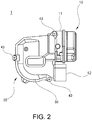
- a motor device 1 As shown in FIGs. 1 and 2 , a motor device 1 according to the embodiment includes a motor part 10 and a gear part 30.
- the motor part 10 and the gear part 30 are connected by a plurality of screws and are integrated.
- the motor part 10 includes a cylindrical yoke 11.
- the yoke 11 is formed in a predetermined shape by performing a pressing process on a plate material (a steel plate, etc.) consisting of a magnetic material.
- a plurality of permanent magnets whose cross-sections are substantially arc-shaped are fixed to the inner side of the yolk 11.
- An armature around which a coil is wound is rotatably disposed at a predetermined gap on the inner side of the permanent magnets.
- an armature shaft 12 ( FIG. 4 ) is disposed on the inner side of the armature. The armature shaft 12 penetrates through the rotational center of the armature and is fixed to the armature.
- a commutator which a plurality of brushes slidably contact is disposed around the armature shaft 12 and supplies a driving current to the coil of the armature via the brushes and the commutator. Then, a rotational force that rotates the armature occurs, and the armature and the armature shaft 12 fixed to the armature rotate.
- the gear part 30 includes a gear case 40 and a gear cover 50.
- the gear case 40 is made of aluminum and formed by forging
- the gear cover 50 is made of synthetic resin and is formed by injection molding.
- the materials and the manufacturing processes of the gear case 40 or the gear cover 50 are not particularly limited.
- the gear case 40 has a bottom part 41 ( FIG. 1 ) and an opening part 42 ( FIG. 3 ), and the gear cover 50 abuts against the gear case 40 to cover the opening part 42 of the gear case 40 and is fixed to the gear case 40 by a plurality of screws 43 ( FIG. 2 ).
- a worm 61 and a worm wheel 62 forming a speed reduction mechanism 60 is accommodated inside the gear case 40 ( FIGs. 1 and 3 ).
- the worm 61 is integral with the armature shaft 12 of the motor part 10 and rotates with the rotation of the armature shaft 12.
- the worm wheel 62 is formed of synthetic resin such as plastics, and is rotatably accommodated inside the gear case 40 ( FIGs. 1 and 3 ).
- a base end side of an output shaft 63 ( FIG. 1 ) whose tip end side protrudes outside the gear case 40 is fixed to the rotational center of the worm wheel 62.
- the output shaft 63 is fixed to the gear case 40 with respect to the axis direction by a fixing washer.
- the tip end side of the output shaft 63 is combined with a link mechanism of the wiper device.
- a plurality of gear teeth 62a are formed on the outer circumferential part of the worm wheel 62, and the gear teeth 62 are meshed with the worm 61.
- the worm 61 and the worm wheel 62 are the forming elements of the speed reduction mechanism 60, and the speed reduction mechanism 60 reduces the rotational speed of the armature shaft 12 to a predetermined rotational speed to increase the output.
- the rotational power with increased output is input to the outside (the link mechanism of the wiper device) via the output shaft 63 shown in FIG. 1 .
- the circuit board 70 is arranged between the speed reduction mechanism 60 ( FIG. 4 ) and the gear cover 50
- the board cover 80 is arranged between the circuit board 70 and the speed reduction mechanism 60.
- the gear cover 50, the circuit board 70, the board cover 80, the speed reduction mechanism 60, and the gear case 40 are arranged in this order.
- the board cover 80 intervenes between the speed reduction mechanism 60 and the circuit board 70.
- the two main surfaces of the board cover 80 are distinguished by referring the main surface on the speed reduction mechanism side as a "first main surface 81", and referring to the main surface on the opposite side to the first main surface 81 as a "second main surface 82".
- the second main surface 82 of the board cover 80 is the main surface on the circuit board side. Nevertheless, such distinction is merely for the convenience of description.
- the entire circuit board 70 has a substantially rectangular shape, and a control circuit, a sensor, etc., are mounted thereon.
- a control circuit formed by various electronic parts such as a capacitor, a choke coil, a CPU, etc., is mounted on the circuit board 70.
- a magnetic sensor such as a Hall IC, that detects magnetic pole changes due to passing of a magnet installed to the worm wheel 62 or the armature shaft 12 is mounted.
- the control circuit supplies the driving current to the brushes based on the detection result of the magnetic sensor, and controls the rotational direction, rotational speed, etc., of the armature shaft 12 ( FIG. 4 ).
- the magnetic sensor is mounted on a surface (front surface) of the circuit board 70 facing the board cover 80, and various electronic components are mounted on the other surface (back surface) of the circuit board 70 facing the gear cover 50. That is, the surface of the circuit board 70 on which the magnetic sensor is mounted faces the second surface 82 of the board cover 80.
- a connector connection part 52 ( FIG. 2 ) connected with an external connector is provided on the gear cover 50. In addition to the detection signal output from the magnetic sensor, a signal input via the connector with which the connector connection part 52 is connected is also input to the control circuit.
- the board cover 80 is formed of synthetic resin such as plastics (polyacetal in the embodiment) and the rigidity thereof is lower than the rigidity of the gear case 40.
- the board cover 80 has a wheel cover part 83 whose cross-section is in a substantially flat shape and a worm cover part 84 whose cross-section is in a substantially semi-circular shape.
- the wheel cover part 83 mainly intervenes between the worm wheel 62 ( FIG. 4 ) and the circuit board 70, and the worm cover part 84 mainly intervenes between the worm 61 ( FIG. 4 ) and the circuit board 70.
- the board cover 80 intervening between the speed reduction mechanism 60 ( FIG.
- the portion (region) mainly positioned between worm wheel 62 and the circuit board 70 is the wheel cover part 83, and the portion (region) mainly positioned between the worm 61 and the circuit board 70 is the worm cover part 84.
- the wheel cover part 83 and the worm cover part 84 are integrally formed of synthetic resin (polyacetal in the embodiment).
- a circular opening part 83a exposing the magnet installed to the worm wheel 62 ( FIG. 4 ) is formed. Accordingly, even though the board cover 80 intervenes between the circuit board 70 and the worm wheel 62, the magnetic pole changes due to passing of the magnet installed to the worm wheel 62 can be reliably detected by the magnetic sensor mounted on the circuit board 70.
- the circuit board 70 is covered by the board cover 80 intervening between the circuit board 70 and the speed reduction mechanism 60. Accordingly, even if the grease coated on the speed reduction mechanism 60 (particularly the portion where the worm 61 and the worm wheel 62 are meshed) scatters as the worm 61 or the worm wheel 62 rotates, the grease does not attach to the circuit board 70, and there is no concern of malfunctioning such as erroneous operation of the control circuit mounted on the circuit board 70 or detection failure of the magnetic sensor.
- a positioning protrusion part 85 protruding toward the gear case 40 is disposed at a corner of the first main surface 81 of the board cover 80. Meanwhile, as shown in FIG. 6 , a positioning recess part 44 is disposed on the gear case 40. As shown in FIG. 3 , the positioning protrusion part 85 is positioned in a vicinity of the worm cover part 84 of the board cover 80. As shown in FIGs. 3 and 5 , on a side of the worm cover part 84, a side wall 86 along the worm cover part 84 is integrally formed, and the positioning protrusion part 85 is integrally formed in a vicinity of the outer side of the side wall 86.
- the positioning protrusion part 85 is arranged on a side opposite to a side on which the worm wheel 62 is disposed to sandwich the worm cover part 84. Accordingly, compared with the case where the positioning protrusion part 85 is arranged in a narrow space where the worm wheel 62 is disposed, the layout of the positioning protrusion part 85 or the speed reduction mechanism 60 has a greater degree of freedom. In addition, the grease can be prevented from entering the positioning recess part 44.
- the positioning protrusion part 85 disposed on the board cover 80 is press-fit into the positioning recess part 44 disposed on the gear case 40.
- the positioning protrusion part 85 disposed on the board cover 80 is press-fit into the positioning recess part 44 disposed on the gear case 40 where the speed reduction 60 ( FIG. 4 ) is incorporated. That is, by press-fitting the positioning protrusion part 85 into the positioning recess part 44, the board cover 80 is accurately positioned with respect to the speed reduction mechanism 60 incorporated into the gear case 40.
- the interference of the speed reduction mechanism 60 can be avoided, the clearance between the speed reduction mechanism and the board cover 80 can be reduced as much as possible, the scattering of the grease can be effectively avoided, and the motor device 1 can be miniaturized.
- the positioning protrusion part 85 is disposed in a vicinity of the worm cover part 84, since the board cover 80 is accurately positioned with respect to the worm 61 whose operation is intense among the forming elements of the speed reduction mechanism 60, the rattles of the board cover 80 is suppressed even if the worm 61 operates intensively.
- the positioning protrusion part 85 has a cylinder-shaped main body part 85a and three collapsed parts 85b protruding from the side surface of the main body part 85a.
- the three collapsed parts 85b are disposed on the outer circumferential surface of the main body part 85b at equal intervals (intervals of 120 degrees).
- the respective collapsed parts 85b are presented in a shape of a substantial isosceles triangle on a cross-section perpendicular to the axis of the main body part 85a.
- each of the collapsed parts 85b has a taper shape in which the amount of protrusion with respect to the main body part 85a gradually decreases from the base end of the collapsed part 85b toward the tip end thereof.
- a width W of the collapsed part 85b shown in (a) of FIG. 7 is the maximum width of the collapsed part 85b, and the value thereof is 0.7 mm.
- the apex angle ( ⁇ 1) shown in the same figure is 45°.
- the taper angle ( ⁇ 2) of the collapsed part 85b shown in (c) of FIG. 7 is 8°.
- the amount of protrusion of the collapsed part 85b with respect to the main body part 85a is at maximum at the base end of the collapsed part 85b and at minimum at the tip end.
- the positioning protrusion part 85 including the collapsed parts 85b gradually tapers off along the pressing direction toward the positioning recess part 44 ( FIG. 6 ), and the outer diameter of the positioning protrusion part 85 is at maximum at the base end thereof and at minimum at the tip end.
- the maximum outer diameter of the positioning protrusion part 85b (the outer diameter of the base end of the positioning protrusion part 85) is greater than the inner diameter of the positioning recess part 44.
- the positioning protrusion part 85 is not completely press-fit into the positioning recess part 44. Specifically, as shown in FIG. 6 , a tip end surface 85c of the positioning protrusion part 85 press-fit into the positioning recess part 44 does not reach a bottom surface 44a of the positioning recess part 44.
- the tip end surface 85c of the positioning protrusion part 85 and the bottom surface 44a of the positioning recess part 44 face each other with a gap (S) therebetween. In this way, by preventing the positioning protrusion part 85 from abutting against (touching the bottom of) the positioning recess part 44, the sealing property between the gear case 40 and the gear cover 50 is ensured.
- the board cover 80 including the positioning protrusion part 85 is formed of synthetic resin such as plastics, and the rigidity thereof is lower than the rigidity of the gear case 40. Accordingly, when the positioning protrusion part 85 is press-fit into the positioning recess part 44, at least a portion of the three collapsed parts 85b disposed on the positioning protrusion part 85 is collapsed by the interference with the inner circumferential surface of the positioning recess part 44. As a result, the collapsed parts 85b and the positioning recess part 44 form an abutment surface on which the gear case 40 and the gear cover 50 abut against each other in opposing directions, and the positioning of the gear case 40 and the gear cover 50 in the opposing directions is further ensured.
- the collapsed parts 85b and the positioning recess part 44 are in close contact with each other, and the force for regulating the rotation about the positioning protrusion part 85 as the axis center becomes stronger. Moreover, since the collapsed amount of the collapsed part 85b can be adjusted by the position at which the gear case 40 and the gear cover 50 are assembled, by absorbing the size errors of the board cover 80, the gear case 40, the gear cover 50, etc., the damages of the board cover 80, the gear case 40, the gear cover 50, etc., caused by excessive press-fitting can be prevented.
- a plurality of case side abutment parts abutting against the periphery of the first main surface 81 of the board cover 80 are disposed on the gear case 40, and a plurality of cover side abutment part abutting against the periphery of the second main surface 82 of the board cover 80 are disposed on the gear cover 50.
- two case side abutment parts 45a and 45b are disposed on the gear case 40, and four cover side abutment parts 51a, 51b, 51c, and 51d are disposed on the gear cover 50.
- the cover side abutment part 51a is arranged at a position corresponding to the positioning protrusion part 85 of the board cover 80.
- the cover side abutment part 51a is disposed at a position facing the positioning recess part 44 or a position arranged in a vicinity thereof (see FIG. 6 ) with the positioning protrusion part 85 being sandwiched therebetween. Accordingly, the collapsed part 85b of the positioning protrusion part 85 abuts against both the gear case 40 and the gear cover 50, and can position the gear case 40 and the gear cover 50 in the facing directions.
- two rotation suppression pins 53 are disposed on the gear cover 50. By inserting the rotation suppression pins 53 into two through holes 87 disposed on the board cover 80, the rotation of the board cover 80 with respect to the gear cover 50 is suppressed.
- FIG. 8 schematically shows the abutment location between each abutment part including the cover side abutment part 51a and the circuit board 70.
- the two circles shown in broken lines indicate the abutment locations between the case side abutment parts 45a and 45b and the circuit board 70.
- the four circles shown in solid lines indicate the abutment locations between the cover side abutment parts 51a, 51b, 51c, and 51d and the circuit board 70.
- the respective abutment parts respectively abut against different positions on the periphery of the circuit board 70.
- case side abutment parts 45a and 45b are arranged on an outer side with respect to a quadrangle enclosed by lines connecting the cover side abutment parts 51a, 51b, 51c, and 51d.
- the board cover 80 in the embodiment is positioned and fixed through being sandwiched by the gear case 40 and the gear cover 50, and is also positioned and fixed by press-fitting the positioning protrusion part disposed thereon into the positioning recess part 44 disposed on the gear case 40. Accordingly, the board cover 80 does not receive an excessive pressure or an unbalanced pressure, and can be accurately positioned and fixed.
- the invention is not limited to the above embodiments, and can be modified in various way without departing from the gist thereof.
- the sizes, numbers, numerical values, and the like described in this specification are all merely examples.
- the sizes, shapes, etc., of the positioning protrusion part 85 shown in FIGs. 7(a) to 7(c) are all merely examples.
- the sizes, shapes, numbers, arrangements, etc., of the positioning protrusion part 85 can be appropriately changed as necessary.
- the material of the board cover 80 including the positioning protrusion part 85 is not limited to polyacetal.
- the positioning protrusion part 85 is press-fit into the positioning recess part 44, it is preferable that the collapsed parts 85b disposed on the positioning protrusion part 85 is collapsed while extending and spreading out without burrs. From this viewpoint, polyacetal having high viscosity is suitable as the material of the board cover 80.
- the invention can be widely applied not only to a motor device as the driving source of a wiper device but also to motor devices used as driving sources of various devices.
- the motor device can be used as a driving source of a wiper device mounted in a vehicle such as an automobile.
Landscapes
- Engineering & Computer Science (AREA)
- General Engineering & Computer Science (AREA)
- Mechanical Engineering (AREA)
- Power Engineering (AREA)
- Microelectronics & Electronic Packaging (AREA)
- Connection Of Motors, Electrical Generators, Mechanical Devices, And The Like (AREA)
- General Details Of Gearings (AREA)
- Motor Or Generator Frames (AREA)
Abstract
Description
- The invention relates to a motor device including a speed reduction mechanism reducing the speed of the rotation of a motor and a control circuit controlling the motor.
- A small size and a high output are required for driving sources of various devices mounted in vehicles such as automobiles. A wiper device is an example of the various devices mounted in vehicles, and a small size and a high output are also required for the driving source of the wiper device. Therefore, motor devices are used as the driving sources of many wiper devices. As an example of the motor device used as the driving source of a wiper device, it is known that the motor device has a motor and a speed reduction mechanism reducing the speed of the rotation of the motor. In such motor device, a rotational power with torque increased through speed reduction by the speed reduction mechanism is output to the outside via an output shaft.
- In addition, as another example of the motor device used as the driving source of a wiper device, the motor device has a control circuit controlling the motor, in addition to the motor and the speed reduction mechanism. Normally, the control circuit is mounted on a circuit board and, for example, controls the speed, the rotation direction, etc., of the motor. The circuit board on which the control circuit is mounted is accommodated inside a housing together with gears, etc, that form the speed reduction mechanism. In such case, in order to prevent grease coated on gears, etc., from scattering and attaching to the circuit board, a cover (board cover) covering the circuit board may be arranged inside the housing.
- Patent Document 1: Japanese Laid-open No.
2011-234453 - The housing accommodating the speed reduction mechanism and the circuit board is formed by a gear cover and a gear case fixed in a state of abutting against each other. In such case, in order to fix the board cover disposed between the gear cover and the gear case, a plurality of protrusion parts or support parts abutting against the board cover are respectively disposed on the gear cover and the gear case.
- However, in the fixing structure of the board cover, due to the variations of part size, the influences of the repulsive force of the seal material intervening between the gear cover and the gear case, etc., there are concerns that the board cover may not be accurately positioned, and rattles may occur. Meanwhile, when the board cover is strongly held to avoid rattles of the board cover, there are concerns that the board cover may be damaged.
- The objective of the invention is to provide a motor device that positions the board cover accurately without rattles and without concerns that the board cover is damaged.
- A motor device of the disclosure includes a motor part including an armature shaft; a speed reduction mechanism which includes a worm and a worm wheel and outputs the rotation of the armature shaft at a reduced speed; a gear case which is provided with a bottom part and an opening part and accommodates the worm and the worm wheel in a rotatable manner; a gear cover which covers the opening part of the gear case; a circuit board which is arranged between the speed reduction mechanism and the gear cover; and a board cover which is arranged between the circuit board and the speed reduction mechanism. The board cover is provided with a positioning protrusion part protruding toward the gear case. The gear case is provided with a positioning recess part into which the positioning protrusion part is press-fit. A bottom surface of the positioning recess part and a tip surface of the positioning protrusion part press-fit into the positioning recess part face each other with a gap therebetween.
- According to an aspect of the invention, the positioning protrusion part has a cylinder-shaped main body part and a plurality of collapsed parts protruding from a side surface of the main body part. In addition, when the positioning protrusion part is press-fit into the positioning recess part, at least a portion of the collapsed parts is collapsed by interference with an inner circumferential surface of the positioning recess part.
- According to another aspect of the invention, the positioning protrusion part is formed to gradually taper off along a pressing direction toward the positioning recess part, and a maximum outer diameter of the positioning protrusion part is greater than an inner diameter of the positioning recess part.
- According to another aspect of the invention, the board cover has a worm cover part intervening between the worm and the circuit board and a wheel cover part intervening between the worm wheel and the circuit board, and the positioning protrusion part is disposed in a vicinity of the worm cover part.
- According to another aspect of the invention, a plurality of case side abutment parts abutting against a first main surface of the board cover on which the positioning protrusion is disposed are disposed on the gear case, and a plurality of cover side abutment parts abutting against a second main surface which is on an opposite side of the first main surface of the board cover are disposed on the gear cover. In addition, at least one of the cover side abutment parts is arranged at a position corresponding to the positioning protrusion part.
- According to another aspect of the invention, two of the case side abutment parts respectively abutting against a periphery of the first main surface are disposed on the gear case, and four of the cover side abutment parts respectively abutting against a periphery of the second main surface are disposed on the gear cover. In addition, the two case side abutment parts are arranged on an outer side with respect to a quadrangle enclosed by lines connecting the four cover side abutment parts.
- According to another aspect of the invention, rigidity of the board cover is lower than rigidity of the gear case.
- According to another aspect of the invention, the board cover including the positioning protrusion part is formed of polyacetal.
- According to the invention, a motor device that positions the board cover accurately without rattles and without concerns that the board cover is damaged is realized.
-
-
FIG. 1 is a view illustrating an appearance of a motor device. -
FIG. 2 is another view illustrating the appearance of the motor device. -
FIG. 3 is a view illustrating an internal structure of the motor device. -
FIG. 4 is a view illustrating a speed reduction mechanism. -
FIG. 5 is a view illustrating an arrangement state of a board cover. -
FIG. 6 is a view illustrating a positioning protrusion part and a positioning recess part. (a) ofFIG. 7 is an oblique view illustrating the positioning protrusion part, (b) ofFIG. 7 is a plan view thereof, and (c) ofFIG. 7 is a cross-sectional view thereof. -
FIG. 8 is a view schematically illustrating an abutment location between an abutment part and the board cover. - In the following, an example of the embodiment of the invention will be described in detail with reference to the drawings. A motor device according to the embodiment is used as the driving source of a wiper device mounted in a vehicle such as an automobile.
- As shown in
FIGs. 1 and2 , amotor device 1 according to the embodiment includes amotor part 10 and agear part 30. Themotor part 10 and thegear part 30 are connected by a plurality of screws and are integrated. - The
motor part 10 includes acylindrical yoke 11. Theyoke 11 is formed in a predetermined shape by performing a pressing process on a plate material (a steel plate, etc.) consisting of a magnetic material. A plurality of permanent magnets whose cross-sections are substantially arc-shaped are fixed to the inner side of theyolk 11. An armature around which a coil is wound is rotatably disposed at a predetermined gap on the inner side of the permanent magnets. In addition, an armature shaft 12 (FIG. 4 ) is disposed on the inner side of the armature. Thearmature shaft 12 penetrates through the rotational center of the armature and is fixed to the armature. A commutator which a plurality of brushes slidably contact is disposed around thearmature shaft 12 and supplies a driving current to the coil of the armature via the brushes and the commutator. Then, a rotational force that rotates the armature occurs, and the armature and thearmature shaft 12 fixed to the armature rotate. - As shown in
FIG. 1 , thegear part 30 includes agear case 40 and agear cover 50. In the embodiment, thegear case 40 is made of aluminum and formed by forging, and thegear cover 50 is made of synthetic resin and is formed by injection molding. However, the materials and the manufacturing processes of thegear case 40 or thegear cover 50 are not particularly limited. - As shown in
FIGs. 1 and3 , thegear case 40 has a bottom part 41 (FIG. 1 ) and an opening part 42 (FIG. 3 ), and thegear cover 50 abuts against thegear case 40 to cover theopening part 42 of thegear case 40 and is fixed to thegear case 40 by a plurality of screws 43 (FIG. 2 ). As shown inFIG. 4 , aworm 61 and aworm wheel 62 forming aspeed reduction mechanism 60 is accommodated inside the gear case 40 (FIGs. 1 and3 ). Theworm 61 is integral with thearmature shaft 12 of themotor part 10 and rotates with the rotation of thearmature shaft 12. Theworm wheel 62 is formed of synthetic resin such as plastics, and is rotatably accommodated inside the gear case 40 (FIGs. 1 and3 ). A base end side of an output shaft 63 (FIG. 1 ) whose tip end side protrudes outside thegear case 40 is fixed to the rotational center of theworm wheel 62. Theoutput shaft 63 is fixed to thegear case 40 with respect to the axis direction by a fixing washer. In addition, the tip end side of theoutput shaft 63 is combined with a link mechanism of the wiper device. - As shown in
FIG. 4 , a plurality ofgear teeth 62a are formed on the outer circumferential part of theworm wheel 62, and thegear teeth 62 are meshed with theworm 61. As described above, theworm 61 and theworm wheel 62 are the forming elements of thespeed reduction mechanism 60, and thespeed reduction mechanism 60 reduces the rotational speed of thearmature shaft 12 to a predetermined rotational speed to increase the output. The rotational power with increased output is input to the outside (the link mechanism of the wiper device) via theoutput shaft 63 shown inFIG. 1 . - As shown in
FIG. 3 andFIG. 5 , thecircuit board 70 is arranged between the speed reduction mechanism 60 (FIG. 4 ) and thegear cover 50, and theboard cover 80 is arranged between thecircuit board 70 and thespeed reduction mechanism 60. In other words, thegear cover 50, thecircuit board 70, theboard cover 80, thespeed reduction mechanism 60, and thegear case 40 are arranged in this order. In other words, theboard cover 80 intervenes between thespeed reduction mechanism 60 and thecircuit board 70. In the following descriptions, the two main surfaces of theboard cover 80 are distinguished by referring the main surface on the speed reduction mechanism side as a "firstmain surface 81", and referring to the main surface on the opposite side to the firstmain surface 81 as a "secondmain surface 82". In other words, the secondmain surface 82 of theboard cover 80 is the main surface on the circuit board side. Nevertheless, such distinction is merely for the convenience of description. - As shown in
FIG. 3 , theentire circuit board 70 has a substantially rectangular shape, and a control circuit, a sensor, etc., are mounted thereon. For example, on thecircuit board 70, a control circuit formed by various electronic parts such as a capacitor, a choke coil, a CPU, etc., is mounted on thecircuit board 70. In addition, on thecircuit board 70, a magnetic sensor, such as a Hall IC, that detects magnetic pole changes due to passing of a magnet installed to theworm wheel 62 or thearmature shaft 12 is mounted. The control circuit supplies the driving current to the brushes based on the detection result of the magnetic sensor, and controls the rotational direction, rotational speed, etc., of the armature shaft 12 (FIG. 4 ). In the embodiment, the magnetic sensor is mounted on a surface (front surface) of thecircuit board 70 facing theboard cover 80, and various electronic components are mounted on the other surface (back surface) of thecircuit board 70 facing thegear cover 50. That is, the surface of thecircuit board 70 on which the magnetic sensor is mounted faces thesecond surface 82 of theboard cover 80. A connector connection part 52 (FIG. 2 ) connected with an external connector is provided on thegear cover 50. In addition to the detection signal output from the magnetic sensor, a signal input via the connector with which theconnector connection part 52 is connected is also input to the control circuit. - As shown in
FIGs. 3 and5 , theboard cover 80 is formed of synthetic resin such as plastics (polyacetal in the embodiment) and the rigidity thereof is lower than the rigidity of thegear case 40. Theboard cover 80 has awheel cover part 83 whose cross-section is in a substantially flat shape and aworm cover part 84 whose cross-section is in a substantially semi-circular shape. The wheel coverpart 83 mainly intervenes between the worm wheel 62 (FIG. 4 ) and thecircuit board 70, and theworm cover part 84 mainly intervenes between the worm 61 (FIG. 4 ) and thecircuit board 70. In other words, in theboard cover 80 intervening between the speed reduction mechanism 60 (FIG. 4 ) and thecircuit board 70, the portion (region) mainly positioned betweenworm wheel 62 and thecircuit board 70 is thewheel cover part 83, and the portion (region) mainly positioned between theworm 61 and thecircuit board 70 is theworm cover part 84. Nevertheless, thewheel cover part 83 and theworm cover part 84 are integrally formed of synthetic resin (polyacetal in the embodiment). - On the
wheel cover part 83 of theboard cover 80, acircular opening part 83a exposing the magnet installed to the worm wheel 62 (FIG. 4 ) is formed. Accordingly, even though theboard cover 80 intervenes between thecircuit board 70 and theworm wheel 62, the magnetic pole changes due to passing of the magnet installed to theworm wheel 62 can be reliably detected by the magnetic sensor mounted on thecircuit board 70. - According to the above, the
circuit board 70 is covered by theboard cover 80 intervening between thecircuit board 70 and thespeed reduction mechanism 60. Accordingly, even if the grease coated on the speed reduction mechanism 60 (particularly the portion where theworm 61 and theworm wheel 62 are meshed) scatters as theworm 61 or theworm wheel 62 rotates, the grease does not attach to thecircuit board 70, and there is no concern of malfunctioning such as erroneous operation of the control circuit mounted on thecircuit board 70 or detection failure of the magnetic sensor. - As shown in
FIG. 3 , apositioning protrusion part 85 protruding toward thegear case 40 is disposed at a corner of the firstmain surface 81 of theboard cover 80. Meanwhile, as shown inFIG. 6 , apositioning recess part 44 is disposed on thegear case 40. As shown inFIG. 3 , thepositioning protrusion part 85 is positioned in a vicinity of theworm cover part 84 of theboard cover 80. As shown inFIGs. 3 and5 , on a side of theworm cover part 84, aside wall 86 along theworm cover part 84 is integrally formed, and thepositioning protrusion part 85 is integrally formed in a vicinity of the outer side of theside wall 86. In addition, thepositioning protrusion part 85 is arranged on a side opposite to a side on which theworm wheel 62 is disposed to sandwich theworm cover part 84. Accordingly, compared with the case where thepositioning protrusion part 85 is arranged in a narrow space where theworm wheel 62 is disposed, the layout of thepositioning protrusion part 85 or thespeed reduction mechanism 60 has a greater degree of freedom. In addition, the grease can be prevented from entering thepositioning recess part 44. - As shown in
FIG. 6 , thepositioning protrusion part 85 disposed on theboard cover 80 is press-fit into thepositioning recess part 44 disposed on thegear case 40. In other words, thepositioning protrusion part 85 disposed on theboard cover 80 is press-fit into thepositioning recess part 44 disposed on thegear case 40 where the speed reduction 60 (FIG. 4 ) is incorporated. That is, by press-fitting thepositioning protrusion part 85 into thepositioning recess part 44, theboard cover 80 is accurately positioned with respect to thespeed reduction mechanism 60 incorporated into thegear case 40. Accordingly, the interference of thespeed reduction mechanism 60 can be avoided, the clearance between the speed reduction mechanism and theboard cover 80 can be reduced as much as possible, the scattering of the grease can be effectively avoided, and themotor device 1 can be miniaturized. In addition, in the embodiment in which thepositioning protrusion part 85 is disposed in a vicinity of theworm cover part 84, since theboard cover 80 is accurately positioned with respect to theworm 61 whose operation is intense among the forming elements of thespeed reduction mechanism 60, the rattles of theboard cover 80 is suppressed even if theworm 61 operates intensively. - As shown in (a) to (c) of
FIG. 7 , thepositioning protrusion part 85 has a cylinder-shapedmain body part 85a and three collapsedparts 85b protruding from the side surface of themain body part 85a. As shown in (b) ofFIG. 7 , the three collapsedparts 85b are disposed on the outer circumferential surface of themain body part 85b at equal intervals (intervals of 120 degrees). The respective collapsedparts 85b are presented in a shape of a substantial isosceles triangle on a cross-section perpendicular to the axis of themain body part 85a. In addition, as shown in (a) ofFIG. 7 , each of thecollapsed parts 85b has a taper shape in which the amount of protrusion with respect to themain body part 85a gradually decreases from the base end of thecollapsed part 85b toward the tip end thereof. A width W of thecollapsed part 85b shown in (a) ofFIG. 7 is the maximum width of thecollapsed part 85b, and the value thereof is 0.7 mm. In addition, the apex angle (θ1) shown in the same figure is 45°. The taper angle (θ2) of thecollapsed part 85b shown in (c) ofFIG. 7 is 8°. - As can be understood from
FIGs. 7(a) to 7(c) , the amount of protrusion of thecollapsed part 85b with respect to themain body part 85a is at maximum at the base end of thecollapsed part 85b and at minimum at the tip end. As a result, thepositioning protrusion part 85 including the collapsedparts 85b gradually tapers off along the pressing direction toward the positioning recess part 44 (FIG. 6 ), and the outer diameter of thepositioning protrusion part 85 is at maximum at the base end thereof and at minimum at the tip end. The maximum outer diameter of thepositioning protrusion part 85b (the outer diameter of the base end of the positioning protrusion part 85) is greater than the inner diameter of thepositioning recess part 44. Accordingly, thepositioning protrusion part 85 is not completely press-fit into thepositioning recess part 44. Specifically, as shown inFIG. 6 , atip end surface 85c of thepositioning protrusion part 85 press-fit into thepositioning recess part 44 does not reach abottom surface 44a of thepositioning recess part 44. Thetip end surface 85c of thepositioning protrusion part 85 and thebottom surface 44a of thepositioning recess part 44 face each other with a gap (S) therebetween. In this way, by preventing thepositioning protrusion part 85 from abutting against (touching the bottom of) thepositioning recess part 44, the sealing property between thegear case 40 and thegear cover 50 is ensured. - In addition, the
board cover 80 including thepositioning protrusion part 85 is formed of synthetic resin such as plastics, and the rigidity thereof is lower than the rigidity of thegear case 40. Accordingly, when thepositioning protrusion part 85 is press-fit into thepositioning recess part 44, at least a portion of the three collapsedparts 85b disposed on thepositioning protrusion part 85 is collapsed by the interference with the inner circumferential surface of thepositioning recess part 44. As a result, thecollapsed parts 85b and thepositioning recess part 44 form an abutment surface on which thegear case 40 and thegear cover 50 abut against each other in opposing directions, and the positioning of thegear case 40 and thegear cover 50 in the opposing directions is further ensured. In addition, thecollapsed parts 85b and thepositioning recess part 44 are in close contact with each other, and the force for regulating the rotation about thepositioning protrusion part 85 as the axis center becomes stronger. Moreover, since the collapsed amount of thecollapsed part 85b can be adjusted by the position at which thegear case 40 and thegear cover 50 are assembled, by absorbing the size errors of theboard cover 80, thegear case 40, thegear cover 50, etc., the damages of theboard cover 80, thegear case 40, thegear cover 50, etc., caused by excessive press-fitting can be prevented. - As shown in
FIG. 3 , a plurality of case side abutment parts abutting against the periphery of the firstmain surface 81 of theboard cover 80 are disposed on thegear case 40, and a plurality of cover side abutment part abutting against the periphery of the secondmain surface 82 of theboard cover 80 are disposed on thegear cover 50. In the embodiment, two caseside abutment parts gear case 40, and four coverside abutment parts gear cover 50. In addition, the coverside abutment part 51a is arranged at a position corresponding to thepositioning protrusion part 85 of theboard cover 80. Specifically, at the time when thegear case 40 abuts against thegear cover 50 with theboard cover 80 sandwiched 80 therebetween, the coverside abutment part 51a is disposed at a position facing thepositioning recess part 44 or a position arranged in a vicinity thereof (seeFIG. 6 ) with thepositioning protrusion part 85 being sandwiched therebetween. Accordingly, thecollapsed part 85b of thepositioning protrusion part 85 abuts against both thegear case 40 and thegear cover 50, and can position thegear case 40 and thegear cover 50 in the facing directions. In addition, two rotation suppression pins 53 are disposed on thegear cover 50. By inserting the rotation suppression pins 53 into two throughholes 87 disposed on theboard cover 80, the rotation of theboard cover 80 with respect to thegear cover 50 is suppressed. -
FIG. 8 schematically shows the abutment location between each abutment part including the coverside abutment part 51a and thecircuit board 70. The two circles shown in broken lines indicate the abutment locations between the caseside abutment parts circuit board 70. In addition, the four circles shown in solid lines indicate the abutment locations between the coverside abutment parts circuit board 70. As shown inFIG. 8 , the respective abutment parts (the caseside abutment parts side abutment parts circuit board 70. In addition, the caseside abutment parts side abutment parts board cover 80 on thegear case 40 as well as thegear cover 50, a well-balanced pressure is applied to theboard cover 80 and theboard cover 80 is held without tilting. - According to the above, the
board cover 80 in the embodiment is positioned and fixed through being sandwiched by thegear case 40 and thegear cover 50, and is also positioned and fixed by press-fitting the positioning protrusion part disposed thereon into thepositioning recess part 44 disposed on thegear case 40. Accordingly, theboard cover 80 does not receive an excessive pressure or an unbalanced pressure, and can be accurately positioned and fixed. - The invention is not limited to the above embodiments, and can be modified in various way without departing from the gist thereof. In addition, the sizes, numbers, numerical values, and the like described in this specification are all merely examples. In particular, the sizes, shapes, etc., of the
positioning protrusion part 85 shown inFIGs. 7(a) to 7(c) are all merely examples. The sizes, shapes, numbers, arrangements, etc., of thepositioning protrusion part 85 can be appropriately changed as necessary. In addition, the material of theboard cover 80 including thepositioning protrusion part 85 is not limited to polyacetal. However, when thepositioning protrusion part 85 is press-fit into thepositioning recess part 44, it is preferable that thecollapsed parts 85b disposed on thepositioning protrusion part 85 is collapsed while extending and spreading out without burrs. From this viewpoint, polyacetal having high viscosity is suitable as the material of theboard cover 80. - The invention can be widely applied not only to a motor device as the driving source of a wiper device but also to motor devices used as driving sources of various devices.
- The motor device can be used as a driving source of a wiper device mounted in a vehicle such as an automobile.
Claims (8)
- A motor device, comprising:a motor part comprising an armature shaft;a speed reduction mechanism which comprises a worm and a worm wheel and outputs rotation of the armature shaft at a reduced speed;a gear case which is provided with a bottom part and an opening part and accommodates the worm and the worm wheel in a rotatable manner;a gear cover which covers the opening part of the gear case;a circuit board which is arranged between the speed reduction mechanism and the gear cover; anda board cover which is arranged between the circuit board and the speed reduction mechanism,wherein the board cover is provided with a positioning protrusion part protruding toward the gear case, the gear case is provided with a positioning recess part into which the positioning protrusion part is press-fit, and a bottom surface of the positioning recess part and a tip end surface of the positioning protrusion part press-fit into the positioning recess part face each other with a gap therebetween.
- The motor device as claimed in claim 1, wherein the positioning protrusion part has a cylinder-shaped main body part and a plurality of collapsed parts protruding from a side surface of the main body part, and when the positioning protrusion part is press-fit into the positioning recess part, at least a portion of the collapsed parts is collapsed by interference with an inner circumferential surface of the positioning recess part.
- The motor device as claimed in claim 2, wherein the positioning protrusion part is formed to gradually taper off along a pressing direction toward the positioning recess part, and a maximum outer diameter of the positioning protrusion part is greater than an inner diameter of the positioning recess part.
- The motor device as claimed in claim 1, wherein the board cover has a worm cover part intervening between the worm and the circuit board and a wheel cover part intervening between the worm wheel and the circuit board, and the positioning protrusion part is disposed in a vicinity of the worm cover part.
- The motor device as claimed in claim 1, wherein a plurality of case side abutment parts abutting against a first main surface of the board cover on which the positioning protrusion is disposed are disposed on the gear case, a plurality of cover side abutment parts abutting against a second main surface which is on an opposite side of the first main surface of the board cover are disposed on the gear cover, and at least one of the cover side abutment parts is arranged at a position corresponding to the positioning protrusion part.
- The motor device as claimed in claim 5, wherein two of the case side abutment parts respectively abutting against a periphery of the first main surface are disposed on the gear case, four of the cover side abutment parts respectively abutting against a periphery of the second main surface are disposed on the gear cover, and the two case side abutment parts are arranged on an outer side with respect to a quadrangle enclosed by lines connecting the four cover side abutment parts.
- The motor device as claimed in claim 1, wherein rigidity of the board cover is lower than rigidity of the gear case.
- The motor device as claimed in claim 7, wherein the board cover comprising the positioning protrusion part is formed of polyacetal.
Applications Claiming Priority (2)
| Application Number | Priority Date | Filing Date | Title |
|---|---|---|---|
| JP2017228650A JP6949685B2 (en) | 2017-11-29 | 2017-11-29 | Motor device |
| PCT/JP2018/039360 WO2019107018A1 (en) | 2017-11-29 | 2018-10-23 | Motor device |
Publications (3)
| Publication Number | Publication Date |
|---|---|
| EP3719974A1 true EP3719974A1 (en) | 2020-10-07 |
| EP3719974A4 EP3719974A4 (en) | 2021-09-01 |
| EP3719974B1 EP3719974B1 (en) | 2024-08-28 |
Family
ID=66664834
Family Applications (1)
| Application Number | Title | Priority Date | Filing Date |
|---|---|---|---|
| EP18883266.1A Active EP3719974B1 (en) | 2017-11-29 | 2018-10-23 | Motor device |
Country Status (5)
| Country | Link |
|---|---|
| US (1) | US11702037B2 (en) |
| EP (1) | EP3719974B1 (en) |
| JP (1) | JP6949685B2 (en) |
| CN (1) | CN111095747B (en) |
| WO (1) | WO2019107018A1 (en) |
Families Citing this family (1)
| Publication number | Priority date | Publication date | Assignee | Title |
|---|---|---|---|---|
| KR102364488B1 (en) * | 2020-07-30 | 2022-02-17 | 캄텍주식회사 | A actuator for a vechicle |
Family Cites Families (9)
| Publication number | Priority date | Publication date | Assignee | Title |
|---|---|---|---|---|
| JP2000188052A (en) * | 1998-12-24 | 2000-07-04 | Kasuga Electric Works Ltd | Adjustable spring structure of thermal overload relay |
| JP5583416B2 (en) | 2009-01-13 | 2014-09-03 | 日本電産サンキョー株式会社 | Motor actuator |
| WO2011013629A1 (en) | 2009-07-30 | 2011-02-03 | 株式会社ミツバ | Motor with speed reduction mechanism |
| JP5595100B2 (en) | 2010-04-26 | 2014-09-24 | 株式会社ミツバ | Motor equipment |
| JP6084003B2 (en) | 2012-10-22 | 2017-02-22 | 日本電産サンキョー株式会社 | Geared motor |
| US20170207684A1 (en) * | 2014-07-15 | 2017-07-20 | Mitsuba Corporation | Brushless wiper motor |
| US10533653B2 (en) | 2014-11-10 | 2020-01-14 | Mitsuba Corporation | Motor with speed reduction mechanism |
| DE102015210648A1 (en) | 2015-06-10 | 2016-12-15 | Siemens Schweiz Ag | actuator |
| JP6532775B2 (en) * | 2015-06-29 | 2019-06-19 | 株式会社ユーシン | Parts positioning structure |
-
2017
- 2017-11-29 JP JP2017228650A patent/JP6949685B2/en active Active
-
2018
- 2018-10-23 EP EP18883266.1A patent/EP3719974B1/en active Active
- 2018-10-23 US US16/644,166 patent/US11702037B2/en active Active
- 2018-10-23 WO PCT/JP2018/039360 patent/WO2019107018A1/en not_active Ceased
- 2018-10-23 CN CN201880057252.4A patent/CN111095747B/en active Active
Also Published As
| Publication number | Publication date |
|---|---|
| CN111095747A (en) | 2020-05-01 |
| US11702037B2 (en) | 2023-07-18 |
| CN111095747B (en) | 2022-03-22 |
| EP3719974B1 (en) | 2024-08-28 |
| JP6949685B2 (en) | 2021-10-13 |
| EP3719974A4 (en) | 2021-09-01 |
| JP2019103167A (en) | 2019-06-24 |
| WO2019107018A1 (en) | 2019-06-06 |
| US20210061230A1 (en) | 2021-03-04 |
Similar Documents
| Publication | Publication Date | Title |
|---|---|---|
| EP2626987B1 (en) | Sensing magnet apparatus for motor | |
| US8193668B2 (en) | Motor with speed reduction mechanism capable of absorbing axial deviation between armature shaft and worm shaft | |
| JP5491275B2 (en) | Motor with reduction gear | |
| JPWO2016010021A1 (en) | Brushless wiper motor | |
| US10533653B2 (en) | Motor with speed reduction mechanism | |
| EP3719974B1 (en) | Motor device | |
| JP2017046405A (en) | Actuator | |
| EP3902115A1 (en) | Rotor, motor, and wiper motor | |
| JP7356600B2 (en) | motor | |
| KR20100016309A (en) | Throttle position sensor assembly | |
| WO2019208076A1 (en) | Motor unit and electric oil pump | |
| JP7203131B2 (en) | motor device | |
| CN203554181U (en) | Motor | |
| JP4626318B2 (en) | Rotation detection sensor | |
| WO2019208073A1 (en) | Motor unit and electric oil pump | |
| WO2019082490A1 (en) | Rotary apparatus | |
| JP6238299B2 (en) | Rotation angle detector | |
| US11578994B2 (en) | Fixing structure | |
| WO2018198235A1 (en) | Rotary actuator and vg actuator | |
| JP4417803B2 (en) | motor | |
| KR20220030688A (en) | Reducer of steering apparatus for vehicle | |
| JP6262291B2 (en) | Motor and vehicle power window device | |
| JP2006062507A (en) | Actuator device | |
| JP2009276241A (en) | Rotational angle detector | |
| JP2009005497A (en) | Motor with reduction gear mechanism |
Legal Events
| Date | Code | Title | Description |
|---|---|---|---|
| STAA | Information on the status of an ep patent application or granted ep patent |
Free format text: STATUS: THE INTERNATIONAL PUBLICATION HAS BEEN MADE |
|
| PUAI | Public reference made under article 153(3) epc to a published international application that has entered the european phase |
Free format text: ORIGINAL CODE: 0009012 |
|
| STAA | Information on the status of an ep patent application or granted ep patent |
Free format text: STATUS: REQUEST FOR EXAMINATION WAS MADE |
|
| 17P | Request for examination filed |
Effective date: 20200304 |
|
| AK | Designated contracting states |
Kind code of ref document: A1 Designated state(s): AL AT BE BG CH CY CZ DE DK EE ES FI FR GB GR HR HU IE IS IT LI LT LU LV MC MK MT NL NO PL PT RO RS SE SI SK SM TR |
|
| AX | Request for extension of the european patent |
Extension state: BA ME |
|
| DAV | Request for validation of the european patent (deleted) | ||
| DAX | Request for extension of the european patent (deleted) | ||
| A4 | Supplementary search report drawn up and despatched |
Effective date: 20210730 |
|
| RIC1 | Information provided on ipc code assigned before grant |
Ipc: H02K 7/116 20060101AFI20210726BHEP Ipc: H02K 11/33 20160101ALI20210726BHEP |
|
| STAA | Information on the status of an ep patent application or granted ep patent |
Free format text: STATUS: EXAMINATION IS IN PROGRESS |
|
| 17Q | First examination report despatched |
Effective date: 20240325 |
|
| GRAP | Despatch of communication of intention to grant a patent |
Free format text: ORIGINAL CODE: EPIDOSNIGR1 |
|
| STAA | Information on the status of an ep patent application or granted ep patent |
Free format text: STATUS: GRANT OF PATENT IS INTENDED |
|
| RIC1 | Information provided on ipc code assigned before grant |
Ipc: F16H 57/02 20120101ALN20240516BHEP Ipc: F16H 57/039 20120101ALI20240516BHEP Ipc: H02K 7/14 20060101ALI20240516BHEP Ipc: H02K 11/33 20160101ALI20240516BHEP Ipc: H02K 7/116 20060101AFI20240516BHEP |
|
| INTG | Intention to grant announced |
Effective date: 20240611 |
|
| GRAS | Grant fee paid |
Free format text: ORIGINAL CODE: EPIDOSNIGR3 |
|
| GRAA | (expected) grant |
Free format text: ORIGINAL CODE: 0009210 |
|
| STAA | Information on the status of an ep patent application or granted ep patent |
Free format text: STATUS: THE PATENT HAS BEEN GRANTED |
|
| AK | Designated contracting states |
Kind code of ref document: B1 Designated state(s): AL AT BE BG CH CY CZ DE DK EE ES FI FR GB GR HR HU IE IS IT LI LT LU LV MC MK MT NL NO PL PT RO RS SE SI SK SM TR |
|
| REG | Reference to a national code |
Ref country code: GB Ref legal event code: FG4D |
|
| REG | Reference to a national code |
Ref country code: CH Ref legal event code: EP |
|
| REG | Reference to a national code |
Ref country code: DE Ref legal event code: R096 Ref document number: 602018073786 Country of ref document: DE |
|
| REG | Reference to a national code |
Ref country code: IE Ref legal event code: FG4D |
|
| REG | Reference to a national code |
Ref country code: LT Ref legal event code: MG9D |
|
| PG25 | Lapsed in a contracting state [announced via postgrant information from national office to epo] |
Ref country code: NO Free format text: LAPSE BECAUSE OF FAILURE TO SUBMIT A TRANSLATION OF THE DESCRIPTION OR TO PAY THE FEE WITHIN THE PRESCRIBED TIME-LIMIT Effective date: 20241128 |
|
| REG | Reference to a national code |
Ref country code: AT Ref legal event code: MK05 Ref document number: 1719069 Country of ref document: AT Kind code of ref document: T Effective date: 20240828 |
|
| PG25 | Lapsed in a contracting state [announced via postgrant information from national office to epo] |
Ref country code: PT Free format text: LAPSE BECAUSE OF FAILURE TO SUBMIT A TRANSLATION OF THE DESCRIPTION OR TO PAY THE FEE WITHIN THE PRESCRIBED TIME-LIMIT Effective date: 20241230 Ref country code: NL Free format text: LAPSE BECAUSE OF FAILURE TO SUBMIT A TRANSLATION OF THE DESCRIPTION OR TO PAY THE FEE WITHIN THE PRESCRIBED TIME-LIMIT Effective date: 20240828 Ref country code: PL Free format text: LAPSE BECAUSE OF FAILURE TO SUBMIT A TRANSLATION OF THE DESCRIPTION OR TO PAY THE FEE WITHIN THE PRESCRIBED TIME-LIMIT Effective date: 20240828 Ref country code: GR Free format text: LAPSE BECAUSE OF FAILURE TO SUBMIT A TRANSLATION OF THE DESCRIPTION OR TO PAY THE FEE WITHIN THE PRESCRIBED TIME-LIMIT Effective date: 20241129 Ref country code: FI Free format text: LAPSE BECAUSE OF FAILURE TO SUBMIT A TRANSLATION OF THE DESCRIPTION OR TO PAY THE FEE WITHIN THE PRESCRIBED TIME-LIMIT Effective date: 20240828 |
|
| PG25 | Lapsed in a contracting state [announced via postgrant information from national office to epo] |
Ref country code: BG Free format text: LAPSE BECAUSE OF FAILURE TO SUBMIT A TRANSLATION OF THE DESCRIPTION OR TO PAY THE FEE WITHIN THE PRESCRIBED TIME-LIMIT Effective date: 20240828 |
|
| PG25 | Lapsed in a contracting state [announced via postgrant information from national office to epo] |
Ref country code: LV Free format text: LAPSE BECAUSE OF FAILURE TO SUBMIT A TRANSLATION OF THE DESCRIPTION OR TO PAY THE FEE WITHIN THE PRESCRIBED TIME-LIMIT Effective date: 20240828 |
|
| REG | Reference to a national code |
Ref country code: NL Ref legal event code: MP Effective date: 20240828 |
|
| PG25 | Lapsed in a contracting state [announced via postgrant information from national office to epo] |
Ref country code: IS Free format text: LAPSE BECAUSE OF FAILURE TO SUBMIT A TRANSLATION OF THE DESCRIPTION OR TO PAY THE FEE WITHIN THE PRESCRIBED TIME-LIMIT Effective date: 20241228 Ref country code: AT Free format text: LAPSE BECAUSE OF FAILURE TO SUBMIT A TRANSLATION OF THE DESCRIPTION OR TO PAY THE FEE WITHIN THE PRESCRIBED TIME-LIMIT Effective date: 20240828 |
|
| PG25 | Lapsed in a contracting state [announced via postgrant information from national office to epo] |
Ref country code: HR Free format text: LAPSE BECAUSE OF FAILURE TO SUBMIT A TRANSLATION OF THE DESCRIPTION OR TO PAY THE FEE WITHIN THE PRESCRIBED TIME-LIMIT Effective date: 20240828 |
|
| PG25 | Lapsed in a contracting state [announced via postgrant information from national office to epo] |
Ref country code: RS Free format text: LAPSE BECAUSE OF FAILURE TO SUBMIT A TRANSLATION OF THE DESCRIPTION OR TO PAY THE FEE WITHIN THE PRESCRIBED TIME-LIMIT Effective date: 20241128 Ref country code: ES Free format text: LAPSE BECAUSE OF FAILURE TO SUBMIT A TRANSLATION OF THE DESCRIPTION OR TO PAY THE FEE WITHIN THE PRESCRIBED TIME-LIMIT Effective date: 20240828 |
|
| PG25 | Lapsed in a contracting state [announced via postgrant information from national office to epo] |
Ref country code: RS Free format text: LAPSE BECAUSE OF FAILURE TO SUBMIT A TRANSLATION OF THE DESCRIPTION OR TO PAY THE FEE WITHIN THE PRESCRIBED TIME-LIMIT Effective date: 20241128 Ref country code: PT Free format text: LAPSE BECAUSE OF FAILURE TO SUBMIT A TRANSLATION OF THE DESCRIPTION OR TO PAY THE FEE WITHIN THE PRESCRIBED TIME-LIMIT Effective date: 20241230 Ref country code: PL Free format text: LAPSE BECAUSE OF FAILURE TO SUBMIT A TRANSLATION OF THE DESCRIPTION OR TO PAY THE FEE WITHIN THE PRESCRIBED TIME-LIMIT Effective date: 20240828 Ref country code: NO Free format text: LAPSE BECAUSE OF FAILURE TO SUBMIT A TRANSLATION OF THE DESCRIPTION OR TO PAY THE FEE WITHIN THE PRESCRIBED TIME-LIMIT Effective date: 20241128 Ref country code: NL Free format text: LAPSE BECAUSE OF FAILURE TO SUBMIT A TRANSLATION OF THE DESCRIPTION OR TO PAY THE FEE WITHIN THE PRESCRIBED TIME-LIMIT Effective date: 20240828 Ref country code: LV Free format text: LAPSE BECAUSE OF FAILURE TO SUBMIT A TRANSLATION OF THE DESCRIPTION OR TO PAY THE FEE WITHIN THE PRESCRIBED TIME-LIMIT Effective date: 20240828 Ref country code: IS Free format text: LAPSE BECAUSE OF FAILURE TO SUBMIT A TRANSLATION OF THE DESCRIPTION OR TO PAY THE FEE WITHIN THE PRESCRIBED TIME-LIMIT Effective date: 20241228 Ref country code: HR Free format text: LAPSE BECAUSE OF FAILURE TO SUBMIT A TRANSLATION OF THE DESCRIPTION OR TO PAY THE FEE WITHIN THE PRESCRIBED TIME-LIMIT Effective date: 20240828 Ref country code: GR Free format text: LAPSE BECAUSE OF FAILURE TO SUBMIT A TRANSLATION OF THE DESCRIPTION OR TO PAY THE FEE WITHIN THE PRESCRIBED TIME-LIMIT Effective date: 20241129 Ref country code: FI Free format text: LAPSE BECAUSE OF FAILURE TO SUBMIT A TRANSLATION OF THE DESCRIPTION OR TO PAY THE FEE WITHIN THE PRESCRIBED TIME-LIMIT Effective date: 20240828 Ref country code: ES Free format text: LAPSE BECAUSE OF FAILURE TO SUBMIT A TRANSLATION OF THE DESCRIPTION OR TO PAY THE FEE WITHIN THE PRESCRIBED TIME-LIMIT Effective date: 20240828 Ref country code: BG Free format text: LAPSE BECAUSE OF FAILURE TO SUBMIT A TRANSLATION OF THE DESCRIPTION OR TO PAY THE FEE WITHIN THE PRESCRIBED TIME-LIMIT Effective date: 20240828 Ref country code: AT Free format text: LAPSE BECAUSE OF FAILURE TO SUBMIT A TRANSLATION OF THE DESCRIPTION OR TO PAY THE FEE WITHIN THE PRESCRIBED TIME-LIMIT Effective date: 20240828 |
|
| PG25 | Lapsed in a contracting state [announced via postgrant information from national office to epo] |
Ref country code: SM Free format text: LAPSE BECAUSE OF FAILURE TO SUBMIT A TRANSLATION OF THE DESCRIPTION OR TO PAY THE FEE WITHIN THE PRESCRIBED TIME-LIMIT Effective date: 20240828 Ref country code: DK Free format text: LAPSE BECAUSE OF FAILURE TO SUBMIT A TRANSLATION OF THE DESCRIPTION OR TO PAY THE FEE WITHIN THE PRESCRIBED TIME-LIMIT Effective date: 20240828 Ref country code: RO Free format text: LAPSE BECAUSE OF FAILURE TO SUBMIT A TRANSLATION OF THE DESCRIPTION OR TO PAY THE FEE WITHIN THE PRESCRIBED TIME-LIMIT Effective date: 20240828 |
|
| PG25 | Lapsed in a contracting state [announced via postgrant information from national office to epo] |
Ref country code: EE Free format text: LAPSE BECAUSE OF FAILURE TO SUBMIT A TRANSLATION OF THE DESCRIPTION OR TO PAY THE FEE WITHIN THE PRESCRIBED TIME-LIMIT Effective date: 20240828 |
|
| PG25 | Lapsed in a contracting state [announced via postgrant information from national office to epo] |
Ref country code: CZ Free format text: LAPSE BECAUSE OF FAILURE TO SUBMIT A TRANSLATION OF THE DESCRIPTION OR TO PAY THE FEE WITHIN THE PRESCRIBED TIME-LIMIT Effective date: 20240828 |
|
| PG25 | Lapsed in a contracting state [announced via postgrant information from national office to epo] |
Ref country code: IT Free format text: LAPSE BECAUSE OF FAILURE TO SUBMIT A TRANSLATION OF THE DESCRIPTION OR TO PAY THE FEE WITHIN THE PRESCRIBED TIME-LIMIT Effective date: 20240828 Ref country code: SK Free format text: LAPSE BECAUSE OF FAILURE TO SUBMIT A TRANSLATION OF THE DESCRIPTION OR TO PAY THE FEE WITHIN THE PRESCRIBED TIME-LIMIT Effective date: 20240828 |
|
| REG | Reference to a national code |
Ref country code: CH Ref legal event code: PL Ref country code: DE Ref legal event code: R097 Ref document number: 602018073786 Country of ref document: DE |
|
| PLBE | No opposition filed within time limit |
Free format text: ORIGINAL CODE: 0009261 |
|
| STAA | Information on the status of an ep patent application or granted ep patent |
Free format text: STATUS: NO OPPOSITION FILED WITHIN TIME LIMIT |
|
| PG25 | Lapsed in a contracting state [announced via postgrant information from national office to epo] |
Ref country code: MC Free format text: LAPSE BECAUSE OF FAILURE TO SUBMIT A TRANSLATION OF THE DESCRIPTION OR TO PAY THE FEE WITHIN THE PRESCRIBED TIME-LIMIT Effective date: 20240828 |
|
| PG25 | Lapsed in a contracting state [announced via postgrant information from national office to epo] |
Ref country code: BE Free format text: LAPSE BECAUSE OF NON-PAYMENT OF DUE FEES Effective date: 20241031 Ref country code: LU Free format text: LAPSE BECAUSE OF NON-PAYMENT OF DUE FEES Effective date: 20241023 |
|
| GBPC | Gb: european patent ceased through non-payment of renewal fee |
Effective date: 20241128 |
|
| PG25 | Lapsed in a contracting state [announced via postgrant information from national office to epo] |
Ref country code: CH Free format text: LAPSE BECAUSE OF NON-PAYMENT OF DUE FEES Effective date: 20241031 |
|
| 26N | No opposition filed |
Effective date: 20250530 |
|
| REG | Reference to a national code |
Ref country code: BE Ref legal event code: MM Effective date: 20241031 |
|
| PG25 | Lapsed in a contracting state [announced via postgrant information from national office to epo] |
Ref country code: SE Free format text: LAPSE BECAUSE OF FAILURE TO SUBMIT A TRANSLATION OF THE DESCRIPTION OR TO PAY THE FEE WITHIN THE PRESCRIBED TIME-LIMIT Effective date: 20240828 |
|
| PG25 | Lapsed in a contracting state [announced via postgrant information from national office to epo] |
Ref country code: GB Free format text: LAPSE BECAUSE OF NON-PAYMENT OF DUE FEES Effective date: 20241128 |
|
| PGFP | Annual fee paid to national office [announced via postgrant information from national office to epo] |
Ref country code: FR Payment date: 20250908 Year of fee payment: 8 |
|
| PG25 | Lapsed in a contracting state [announced via postgrant information from national office to epo] |
Ref country code: IE Free format text: LAPSE BECAUSE OF NON-PAYMENT OF DUE FEES Effective date: 20241023 |
|
| PGFP | Annual fee paid to national office [announced via postgrant information from national office to epo] |
Ref country code: DE Payment date: 20250902 Year of fee payment: 8 |
|
| PG25 | Lapsed in a contracting state [announced via postgrant information from national office to epo] |
Ref country code: CY Free format text: LAPSE BECAUSE OF FAILURE TO SUBMIT A TRANSLATION OF THE DESCRIPTION OR TO PAY THE FEE WITHIN THE PRESCRIBED TIME-LIMIT; INVALID AB INITIO Effective date: 20181023 |
|
| PG25 | Lapsed in a contracting state [announced via postgrant information from national office to epo] |
Ref country code: HU Free format text: LAPSE BECAUSE OF FAILURE TO SUBMIT A TRANSLATION OF THE DESCRIPTION OR TO PAY THE FEE WITHIN THE PRESCRIBED TIME-LIMIT; INVALID AB INITIO Effective date: 20181023 |