EP3719934B1 - Power connection device for an electric battery and connection assembly comprising this device - Google Patents
Power connection device for an electric battery and connection assembly comprising this device Download PDFInfo
- Publication number
- EP3719934B1 EP3719934B1 EP20167335.7A EP20167335A EP3719934B1 EP 3719934 B1 EP3719934 B1 EP 3719934B1 EP 20167335 A EP20167335 A EP 20167335A EP 3719934 B1 EP3719934 B1 EP 3719934B1
- Authority
- EP
- European Patent Office
- Prior art keywords
- cage
- busbar
- wall
- connection device
- pad
- Prior art date
- Legal status (The legal status is an assumption and is not a legal conclusion. Google has not performed a legal analysis and makes no representation as to the accuracy of the status listed.)
- Active
Links
Images


Classifications
-
- H—ELECTRICITY
- H01—ELECTRIC ELEMENTS
- H01R—ELECTRICALLY-CONDUCTIVE CONNECTIONS; STRUCTURAL ASSOCIATIONS OF A PLURALITY OF MUTUALLY-INSULATED ELECTRICAL CONNECTING ELEMENTS; COUPLING DEVICES; CURRENT COLLECTORS
- H01R11/00—Individual connecting elements providing two or more spaced connecting locations for conductive members which are, or may be, thereby interconnected, e.g. end pieces for wires or cables supported by the wire or cable and having means for facilitating electrical connection to some other wire, terminal, or conductive member, blocks of binding posts
- H01R11/11—End pieces or tapping pieces for wires, supported by the wire and for facilitating electrical connection to some other wire, terminal or conductive member
- H01R11/28—End pieces consisting of a ferrule or sleeve
- H01R11/281—End pieces consisting of a ferrule or sleeve for connections to batteries
- H01R11/288—Interconnections between batteries
-
- H—ELECTRICITY
- H01—ELECTRIC ELEMENTS
- H01R—ELECTRICALLY-CONDUCTIVE CONNECTIONS; STRUCTURAL ASSOCIATIONS OF A PLURALITY OF MUTUALLY-INSULATED ELECTRICAL CONNECTING ELEMENTS; COUPLING DEVICES; CURRENT COLLECTORS
- H01R4/00—Electrically-conductive connections between two or more conductive members in direct contact, i.e. touching one another; Means for effecting or maintaining such contact; Electrically-conductive connections having two or more spaced connecting locations for conductors and using contact members penetrating insulation
- H01R4/28—Clamped connections, spring connections
- H01R4/48—Clamped connections, spring connections utilising a spring, clip, or other resilient member
-
- H—ELECTRICITY
- H01—ELECTRIC ELEMENTS
- H01M—PROCESSES OR MEANS, e.g. BATTERIES, FOR THE DIRECT CONVERSION OF CHEMICAL ENERGY INTO ELECTRICAL ENERGY
- H01M50/00—Constructional details or processes of manufacture of the non-active parts of electrochemical cells other than fuel cells, e.g. hybrid cells
- H01M50/50—Current conducting connections for cells or batteries
- H01M50/502—Interconnectors for connecting terminals of adjacent batteries; Interconnectors for connecting cells outside a battery casing
- H01M50/505—Interconnectors for connecting terminals of adjacent batteries; Interconnectors for connecting cells outside a battery casing comprising a single busbar
-
- H—ELECTRICITY
- H01—ELECTRIC ELEMENTS
- H01M—PROCESSES OR MEANS, e.g. BATTERIES, FOR THE DIRECT CONVERSION OF CHEMICAL ENERGY INTO ELECTRICAL ENERGY
- H01M50/00—Constructional details or processes of manufacture of the non-active parts of electrochemical cells other than fuel cells, e.g. hybrid cells
- H01M50/50—Current conducting connections for cells or batteries
- H01M50/502—Interconnectors for connecting terminals of adjacent batteries; Interconnectors for connecting cells outside a battery casing
- H01M50/521—Interconnectors for connecting terminals of adjacent batteries; Interconnectors for connecting cells outside a battery casing characterised by the material
- H01M50/522—Inorganic material
-
- H—ELECTRICITY
- H01—ELECTRIC ELEMENTS
- H01R—ELECTRICALLY-CONDUCTIVE CONNECTIONS; STRUCTURAL ASSOCIATIONS OF A PLURALITY OF MUTUALLY-INSULATED ELECTRICAL CONNECTING ELEMENTS; COUPLING DEVICES; CURRENT COLLECTORS
- H01R13/00—Details of coupling devices of the kinds covered by groups H01R12/70 or H01R24/00 - H01R33/00
- H01R13/02—Contact members
-
- H—ELECTRICITY
- H01—ELECTRIC ELEMENTS
- H01R—ELECTRICALLY-CONDUCTIVE CONNECTIONS; STRUCTURAL ASSOCIATIONS OF A PLURALITY OF MUTUALLY-INSULATED ELECTRICAL CONNECTING ELEMENTS; COUPLING DEVICES; CURRENT COLLECTORS
- H01R13/00—Details of coupling devices of the kinds covered by groups H01R12/70 or H01R24/00 - H01R33/00
- H01R13/02—Contact members
- H01R13/10—Sockets for co-operation with pins or blades
- H01R13/11—Resilient sockets
- H01R13/113—Resilient sockets co-operating with pins or blades having a rectangular transverse section
-
- H—ELECTRICITY
- H01—ELECTRIC ELEMENTS
- H01R—ELECTRICALLY-CONDUCTIVE CONNECTIONS; STRUCTURAL ASSOCIATIONS OF A PLURALITY OF MUTUALLY-INSULATED ELECTRICAL CONNECTING ELEMENTS; COUPLING DEVICES; CURRENT COLLECTORS
- H01R31/00—Coupling parts supported only by co-operation with counterpart
- H01R31/06—Intermediate parts for linking two coupling parts, e.g. adapter
-
- H—ELECTRICITY
- H01—ELECTRIC ELEMENTS
- H01R—ELECTRICALLY-CONDUCTIVE CONNECTIONS; STRUCTURAL ASSOCIATIONS OF A PLURALITY OF MUTUALLY-INSULATED ELECTRICAL CONNECTING ELEMENTS; COUPLING DEVICES; CURRENT COLLECTORS
- H01R35/00—Flexible or turnable line connectors, i.e. the rotation angle being limited
- H01R35/02—Flexible line connectors without frictional contact members
-
- H—ELECTRICITY
- H01—ELECTRIC ELEMENTS
- H01M—PROCESSES OR MEANS, e.g. BATTERIES, FOR THE DIRECT CONVERSION OF CHEMICAL ENERGY INTO ELECTRICAL ENERGY
- H01M2220/00—Batteries for particular applications
- H01M2220/20—Batteries in motive systems, e.g. vehicle, ship, plane
-
- Y—GENERAL TAGGING OF NEW TECHNOLOGICAL DEVELOPMENTS; GENERAL TAGGING OF CROSS-SECTIONAL TECHNOLOGIES SPANNING OVER SEVERAL SECTIONS OF THE IPC; TECHNICAL SUBJECTS COVERED BY FORMER USPC CROSS-REFERENCE ART COLLECTIONS [XRACs] AND DIGESTS
- Y02—TECHNOLOGIES OR APPLICATIONS FOR MITIGATION OR ADAPTATION AGAINST CLIMATE CHANGE
- Y02E—REDUCTION OF GREENHOUSE GAS [GHG] EMISSIONS, RELATED TO ENERGY GENERATION, TRANSMISSION OR DISTRIBUTION
- Y02E60/00—Enabling technologies; Technologies with a potential or indirect contribution to GHG emissions mitigation
- Y02E60/10—Energy storage using batteries
Definitions
- the invention relates to the field of battery connection technology.
- the invention relates to connection devices making it possible to interconnect battery cells and notably battery cells for electric or rechargeable hybrid motor vehicles.
- batteries for electric or rechargeable hybrid motor vehicles are composed of packets of cells.
- the cells within these packets or between the packets are connected by means of busbars ("busbars" being the English term) fastened onto the cells using a screw and nut system.
- busbars being the English term
- one solution consists of increasing the number of interconnected cells. This therefore results in an increase in the number of nuts to be screwed and the consequences of this notably include an increase in the assembly time and the risk of having a busbar that is poorly screwed and therefore poorly connected (the number of screw turns, the screwing torques, etc. are not easily controllable parameters).
- An example of solution attempting to address this problem is disclosed in the document FR3062956A1 .
- the current technology does not provide much flexibility in terms of tolerances.
- the quality problems which can result in having to change the battery must be avoided.
- the purpose of the invention is to reduce, at least partially, at least one of the abovementioned disadvantages.
- a power connection device for an electric battery comprises a busbar, at least one cage and at least one contact pad.
- Each cage itself comprises two walls (a first wall and a second wall) essentially parallel with and opposite each other.
- Each cage also comprises elastic means (these elastic means comprise for example a spring leaf extending away from one of the walls and designed to retain and compress the elements inserted in the cage against each other.
- the busbar comprises at least one end inserted in a cage. For example, at the level of this free end, the busbar is placed beside one of the two walls of this cage (the first wall), and/or against this wall, leaving a space between the busbar and the other wall (the second wall) of this cage.
- Each contact pad is made from an electrically conductive metal.
- Each contact pad is inserted in an opening formed in the busbar, at the level of its end inserted in the cage.
- Each contact pad protrudes, in said space, on a surface of the busbar, towards the other wall of the cage (the second wall).
- the flexible means are designed to clamp, against a contact pad, at least a portion of a tab inserted into the cage between this contact pad and the second wall.
- a conductive tab protruding on a battery cell can be inserted into a cage, in the space located between a contact pad and the wall which is opposite it. This tab is then held in the cage and pushed against the contact pad by the elastic means.
- a cage can be made from a first material chosen for its mechanical properties and for its rigidity in particular.
- the busbar and the contact pad can be made from a second material chosen for its electrical conduction properties.
- connection device possibly comprises one and/or the other of the features listed in Claims 2 to 10, each considered independently of each other or in combination with one or more others.
- the invention relates to a connection assembly comprising a connection device such as mentioned above and a tab electrically connected to a battery cell.
- the tab is inserted in a cage between its contact pad and the wall of that cage opposite to the one against which the end of the busbar is placed, the elastic means maintaining at least a portion of the tab inserted into this cage clamped against the corresponding contact pad.
- the tab inserted into the cage is possibly made from copper having a percentage purity greater than 99% according to the International Annealed Copper Standard ("ICAS").
- ICAS International Annealed Copper Standard
- connection assembly electrically connects two poles, positive and negative respectively, of two battery cells 2.
- the connection assembly comprises a connection device 1 and two tabs 15 (see a tab 15 in Figure 8 ). It also comprises various casing components 3 notably intended to provide it with protection according to the IP2X standard.
- busbar 4 provided with a cage 5 at each of its longitudinal ends (see Figure 2 - a single cage 5 is shown in Figure 2 ). One of these ends is shown in greater detail and at another viewing angle in Figure 3 .
- Each cage is formed by cutting and stamping from a sheet of stainless steel having a thickness of between 400 and 1200 micrometres. For example, it has a thickness of greater than or equal to 800 micrometres or greater than or equal to 1 millimetre.
- FIG 4 it has an overall "U” shape with two main walls, 6, 7 (corresponding to the uprights of the "U") and a connecting wall 8 (corresponding to the base of the "U").
- the two main walls 6, 7 are essentially parallel.
- the connecting wall 8 extends essentially in a plane perpendicular to the main walls 6, 7.
- the connecting wall 8 connects the two main walls 6, 7 to each other.
- the cage 5 comprises an upper edge 9 and a lower edge 10 each respectively extending in a plane perpendicular to the main walls 6, 7 and to the connecting wall 8.
- a first main wall 6 comprises, close to the upper edge 9 and lower edge 10 of the cage 5, a hook 11 turning back towards the interior of the cage.
- the cage 5 also comprises a lug 12 extending from the first wall 6, towards the interior of the cage 5.
- the first main wall 6 comprises, on one side, a flange extending parallel to the connecting wall 8 and opposite the latter, and turning towards the interior of the cage 5.
- a second main wall 7 comprises elastic means. More particularly, a rectangular or square spring leaf 13 is cut out in this second wall 7 on three sides and remains retained in the second wall 7 on a fourth side 14 which is not cut out.
- This fourth side 14 is essentially parallel with the lower edge 10 of the cage 5 and is located towards the lower edge 10.
- the spring leaf 13 is curved, starting from this fourth side 14 towards the interior of the cage 5 and then again curved towards the second wall 7.
- a tab 15 inserted into the cage 5 can apply pressure onto the spring leaf 13 in such a way as to flatten it towards the second wall 7 and/or to push it back into the cut-out which has been produced in the second wall 7 in order to produce the spring leaf 13 (see Figure 8 also).
- the busbar 4 is formed of several layers 16 disposed one upon the other (see Figure 3 ). For example, it is constituted by six layers 16.
- the technology used for producing the busbar is for example of type of that described in the European Patent application lodged with the reference number EP17207129 .
- the width LB of the busbar 4 is between 15 and 25 millimetres. Preferably, it has a width LB of 23 millimetres.
- the thickness EB of the busbar is of the order of 3 millimetres.
- Each of the layers 16 is composed of copper having a percentage purity greater than 99% according to the International Annealed Copper Standard. It is thus suitable for conducting a current of 400 Amps without generating a heating up to higher than 65°C.
- the busbar 4 comprises a free end with a connection portion, corresponding to the portion of the busbar 17 inserted into the cage 5 (see Figure 2 ).
- the busbar 4 also comprises a flexible portion 18 extending the connection portion 17, to the outside of the cage 5.
- This flexible portion 18 comprises at least one elbow bend 19.
- the flexible portion 18 comprises a bend 19 at 180°, in the shape of a "U", in such a way that a straight portion 20 turns back towards the cage 5 (see Figure 3 ).
- This straight portion is essentially parallel with the first wall 6, in a plane passing outside of the cage 5 and opposite, with respect to the first wall 6, to the one in which the second wall 7 extends.
- the straight portion 20 is followed by another bend 21 at about 45° of the straight portion 20, turning away from the cage 5.
- This configuration of the busbar 4 provides it with a certain flexibility to accommodate variations in the positions of the cells 2 with respect to each other. This therefore makes it possible to ensure the good positioning of a battery tab 15 in the cage 5 and therefore the good electrical contact of this tab 15 and the busbar 4. This is so whatever the tolerances in the positioning of the cells 2 in the battery may be (tolerances of a few millimetres, for example of the order of 2 millimetres can be compensated for thanks to the flexibility of the busbar 4).
- the busbar 4 comprises an opening 22 at the level of its connection portion 17 (see Figure 5 ). It is a cylindrical hole with an axis AS of cylindrical symmetry essentially perpendicular to the plane of the connection portion 17. This hole passes through all of the constituent layers 16 of the busbar 4.
- a contact pad 23 is inserted into the opening 22.
- the pad 23 has a cylindrical revolution shape about a central axis (colinear with the axis of symmetry AS of the opening 22). It comprises a front face 24, a rear face 25 and an external cylindrical wall 26 extending between the rear face 25 and the front face 24 (see Figures 6 and 7 ).
- the cylindrical wall has a length LP sufficient to be in contact with each of the layers 16 of the busbar 4 in such a way that the current paths are distributed as uniformly as possible between the contact pad 23 and each of the layers 16.
- the cylindrical wall has a length LP of the order of 3 millimetres (that is to say in a direction parallel with the central axis AS).
- the front face 24 is obturated by a disk whose thickness ED is of the order of 2 millimetres (that is to say in a direction parallel with the central axis AS).
- the front face 24 comprises a toroidal rib 27 extending over a distance DN of the order of 1 millimetre, starting from the front face 24 in a direction parallel with the central axis AS.
- the peak of the rib is flattened or rounded. For example, it is rounded with a curvature of 1.5 millimetres.
- the rib 27 extends in a circular manner around the central axis AS over a length LN, for example greater than or equal to 24 millimetres.
- the rib 27 has a diameter greater than 3 millimetres, preferably greater than 6 millimetres, for example approximately equal to 8 millimetres.
- the pad 23 is made of copper having a percentage purity greater than 99% according to the International Annealed Copper Standard (but it should be noted that with a copper alloy, having a percentage purity greater than 50% according to the International Annealed Copper Standard, it would also be possible to obtain acceptable results). It is covered, at least at the level of the rib 27 with a layer of electrodeposited silver of 1.5 to 5 micrometres, and advantageously greater than 3 micrometres.
- the contact resistance between the pad 23 and a tab 15 inserted into the cage 5 and pressed against the pad 23 with a normal force of 60 Newtons is of the order of 6 to 10 micro-ohms (for the described example, it is sought to obtain a Hertz pressure of 100 to 200 MPa).
- the pad 23 is force-fitted in the opening 22 formed in the connection portion 17.
- the external cylindrical surface of the pad 23 is in contact with each of the constituent layers 16 of the busbar 4.
- the current paths passing through the pad 23 can therefore be distributed in the different layers 16.
- the circular distribution of the current paths around the external cylindrical wall 26 is also a factor having a positive influence by reducing the constriction resistance.
- the technology used, comprising the force-fitting of the pad 23 in an adjusted manner in the opening 22, which is itself produced by perforation of the layers 16 by punching, is a relatively simple technology to use industrially (in comparison with electric or ultrasonic welding), and makes it possible moreover to optimize the distribution of the current paths in the busbar.
- other technologies welding of a pad, deformation of at least one of the layers 16 in order in some way to form a pad 23 in one piece with the busbar 4, etc.
- connection portion 17, provided with a pad 23 is inserted into the cage 5, by the upper edge 9.
- the busbar 4 is held in the cage 5 by means of the hooks 11 (possibly cooperating with notches formed in the busbar 4) and of the lug 12, against the first wall 6.
- the hooks 11 make it possible to clip the busbar 4 in the cage 5.
- connection device 1 is then obtained, a part of which is shown in Figure 8 .
- a space 28 is formed between the busbar 4 and the second wall 7.
- the pad 23 protrudes into this space 28.
- the cage 5 is formed from a sheet of stainless steel whilst the pad 23 is formed from copper having a high degree of purity.
- Stainless steel is mechanically more rigid than copper (which is relatively ductile) but it is as good a conductor as copper having a high degree of purity. According to the invention, it is therefore possible to benefit from a rigid cage 5, which provides a high contact force but which does not take part in the electrical conduction, and a good electrical connection between the pad 23 and the tab 15 on the one hand and between the pad 23 and the busbar 4 on the other hand.
- the deposit of a layer of silver which further improves the conductivity at the level of the contact between the rib 27 and the tab 15, is limited to the pad 23 so as to limit the manufacturing cost of the device according to the invention, if such a layer of silver is used.
- connection assembly between the connection device 1 and the tab 15 can be further improved if the tab 15 is made from copper having a purity greater than 99% according to the International Annealed Copper Standard.
- the current flows through various components made of copper having a purity greater than 99% according to the International Annealed Copper Standard.
Landscapes
- Chemical & Material Sciences (AREA)
- Chemical Kinetics & Catalysis (AREA)
- Electrochemistry (AREA)
- General Chemical & Material Sciences (AREA)
- Inorganic Chemistry (AREA)
- Connection Of Batteries Or Terminals (AREA)
- Connections Effected By Soldering, Adhesion, Or Permanent Deformation (AREA)
- Secondary Cells (AREA)
Description
- The invention relates to the field of battery connection technology. For example, the invention relates to connection devices making it possible to interconnect battery cells and notably battery cells for electric or rechargeable hybrid motor vehicles.
- At present, batteries for electric or rechargeable hybrid motor vehicles are composed of packets of cells. The cells within these packets or between the packets are connected by means of busbars ("busbars" being the English term) fastened onto the cells using a screw and nut system. In order to increase the autonomy of the vehicles, one solution consists of increasing the number of interconnected cells. This therefore results in an increase in the number of nuts to be screwed and the consequences of this notably include an increase in the assembly time and the risk of having a busbar that is poorly screwed and therefore poorly connected (the number of screw turns, the screwing torques, etc. are not easily controllable parameters). An example of solution attempting to address this problem is disclosed in the document
FR3062956A1 - The purpose of the invention is to reduce, at least partially, at least one of the abovementioned disadvantages.
- For this purpose, according to the invention, a power connection device for an electric battery is proposed. This device comprises a busbar, at least one cage and at least one contact pad. Each cage itself comprises two walls (a first wall and a second wall) essentially parallel with and opposite each other. Each cage also comprises elastic means (these elastic means comprise for example a spring leaf extending away from one of the walls and designed to retain and compress the elements inserted in the cage against each other. The busbar comprises at least one end inserted in a cage. For example, at the level of this free end, the busbar is placed beside one of the two walls of this cage (the first wall), and/or against this wall, leaving a space between the busbar and the other wall (the second wall) of this cage. Each contact pad is made from an electrically conductive metal. Each contact pad is inserted in an opening formed in the busbar, at the level of its end inserted in the cage. Each contact pad protrudes, in said space, on a surface of the busbar, towards the other wall of the cage (the second wall). The flexible means are designed to clamp, against a contact pad, at least a portion of a tab inserted into the cage between this contact pad and the second wall.
- Thus, a conductive tab protruding on a battery cell can be inserted into a cage, in the space located between a contact pad and the wall which is opposite it. This tab is then held in the cage and pushed against the contact pad by the elastic means.
- An electrical connection is thus formed between the tab and the busbar, by the intermediary of the contact pad, and this happens without having recourse to a screw and nut system.
- Moreover, a cage can be made from a first material chosen for its mechanical properties and for its rigidity in particular. The busbar and the contact pad can be made from a second material chosen for its electrical conduction properties.
- The connection device according to the invention possibly comprises one and/or the other of the features listed in
Claims 2 to 10, each considered independently of each other or in combination with one or more others. - According to another aspect, the invention relates to a connection assembly comprising a connection device such as mentioned above and a tab electrically connected to a battery cell. The tab is inserted in a cage between its contact pad and the wall of that cage opposite to the one against which the end of the busbar is placed, the elastic means maintaining at least a portion of the tab inserted into this cage clamped against the corresponding contact pad.
- The tab inserted into the cage is possibly made from copper having a percentage purity greater than 99% according to the International Annealed Copper Standard ("ICAS").
- Other features, purposes and advantages of the invention will become apparent on reading the following detailed description given with reference to the appended drawings and by way of non-limiting examples and in which:
-
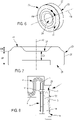
Figure 1 is a diagrammatic representation in perspective of two battery cells connected together by an example of a connection device according to the invention; -
Figure 2 is a diagrammatic representation in perspective of the busbar of the connection device shown inFigure 1 , this busbar being provided with a cage at each of its longitudinal ends; -
Figure 3 is a diagrammatic representation in perspective of one end of the busbar shown inFigure 2 , provided with a cage; -
Figure 4 is a diagrammatic representation in perspective of a cage such as the one fitted on the busbar shown inFigures 2 and 3 ; -
Figure 5 is a diagrammatic exploded representation in perspective of one end of the busbar shown inFigures 2 and 3 , with a contact pad intended to be mounted on it; -
Figure 6 is a diagrammatic representation in perspective of a contact pad as shown inFigure 5 ; -
Figure 7 is a diagrammatic representation in cross-section of the contact pad shown inFigure 6 ; and -
Figure 8 is a diagrammatic representation in partial cross-section of the connection assembly shown inFigure 1 with a tab inserted into the cage. - An example embodiment of a connection assembly according to the invention is shown in
Figure 1 . According to this example, the connection assembly electrically connects two poles, positive and negative respectively, of twobattery cells 2. The connection assembly comprises aconnection device 1 and two tabs 15 (see atab 15 inFigure 8 ). It also comprisesvarious casing components 3 notably intended to provide it with protection according to the IP2X standard. In fact, inside eachcasing 3 there is abusbar 4 provided with acage 5 at each of its longitudinal ends (seeFigure 2 - asingle cage 5 is shown inFigure 2 ). One of these ends is shown in greater detail and at another viewing angle inFigure 3 . - Each cage is formed by cutting and stamping from a sheet of stainless steel having a thickness of between 400 and 1200 micrometres. For example, it has a thickness of greater than or equal to 800 micrometres or greater than or equal to 1 millimetre.
- As shown in
Figure 4 , it has an overall "U" shape with two main walls, 6, 7 (corresponding to the uprights of the "U") and a connecting wall 8 (corresponding to the base of the "U"). The twomain walls 6, 7 are essentially parallel. Theconnecting wall 8 extends essentially in a plane perpendicular to themain walls 6, 7. Theconnecting wall 8 connects the twomain walls 6, 7 to each other. Thecage 5 comprises anupper edge 9 and alower edge 10 each respectively extending in a plane perpendicular to themain walls 6, 7 and to theconnecting wall 8. - A first
main wall 6 comprises, close to theupper edge 9 andlower edge 10 of thecage 5, ahook 11 turning back towards the interior of the cage. At the level of thelower edge 10, thecage 5 also comprises alug 12 extending from thefirst wall 6, towards the interior of thecage 5. Alternatively, according to a variant which is not shown, the firstmain wall 6 comprises, on one side, a flange extending parallel to the connectingwall 8 and opposite the latter, and turning towards the interior of thecage 5. - A second main wall 7 comprises elastic means. More particularly, a rectangular or
square spring leaf 13 is cut out in this second wall 7 on three sides and remains retained in the second wall 7 on afourth side 14 which is not cut out. Thisfourth side 14 is essentially parallel with thelower edge 10 of thecage 5 and is located towards thelower edge 10. Thespring leaf 13 is curved, starting from thisfourth side 14 towards the interior of thecage 5 and then again curved towards the second wall 7. Thus, atab 15 inserted into thecage 5 can apply pressure onto thespring leaf 13 in such a way as to flatten it towards the second wall 7 and/or to push it back into the cut-out which has been produced in the second wall 7 in order to produce the spring leaf 13 (seeFigure 8 also). - The
busbar 4 is formed ofseveral layers 16 disposed one upon the other (seeFigure 3 ). For example, it is constituted by sixlayers 16. The technology used for producing the busbar is for example of type of that described in the European Patent application lodged with the reference numberEP17207129 busbar 4 is between 15 and 25 millimetres. Preferably, it has a width LB of 23 millimetres. The thickness EB of the busbar is of the order of 3 millimetres. Each of thelayers 16 is composed of copper having a percentage purity greater than 99% according to the International Annealed Copper Standard. It is thus suitable for conducting a current of 400 Amps without generating a heating up to higher than 65°C. - The
busbar 4 comprises a free end with a connection portion, corresponding to the portion of thebusbar 17 inserted into the cage 5 (seeFigure 2 ). Thebusbar 4 also comprises aflexible portion 18 extending theconnection portion 17, to the outside of thecage 5. Thisflexible portion 18 comprises at least oneelbow bend 19. For example, theflexible portion 18 comprises abend 19 at 180°, in the shape of a "U", in such a way that astraight portion 20 turns back towards the cage 5 (seeFigure 3 ). This straight portion is essentially parallel with thefirst wall 6, in a plane passing outside of thecage 5 and opposite, with respect to thefirst wall 6, to the one in which the second wall 7 extends. - Close to the
upper edge 9 of thecage 5, thestraight portion 20 is followed by anotherbend 21 at about 45° of thestraight portion 20, turning away from thecage 5. This configuration of thebusbar 4 provides it with a certain flexibility to accommodate variations in the positions of thecells 2 with respect to each other. This therefore makes it possible to ensure the good positioning of abattery tab 15 in thecage 5 and therefore the good electrical contact of thistab 15 and thebusbar 4. This is so whatever the tolerances in the positioning of thecells 2 in the battery may be (tolerances of a few millimetres, for example of the order of 2 millimetres can be compensated for thanks to the flexibility of the busbar 4). - The
busbar 4 comprises anopening 22 at the level of its connection portion 17 (seeFigure 5 ). It is a cylindrical hole with an axis AS of cylindrical symmetry essentially perpendicular to the plane of theconnection portion 17. This hole passes through all of theconstituent layers 16 of thebusbar 4. - A
contact pad 23 is inserted into theopening 22. Thepad 23 has a cylindrical revolution shape about a central axis (colinear with the axis of symmetry AS of the opening 22). It comprises afront face 24, arear face 25 and an externalcylindrical wall 26 extending between therear face 25 and the front face 24 (seeFigures 6 and 7 ). The cylindrical wall has a length LP sufficient to be in contact with each of thelayers 16 of thebusbar 4 in such a way that the current paths are distributed as uniformly as possible between thecontact pad 23 and each of thelayers 16. For example, the cylindrical wall has a length LP of the order of 3 millimetres (that is to say in a direction parallel with the central axis AS). Thefront face 24 is obturated by a disk whose thickness ED is of the order of 2 millimetres (that is to say in a direction parallel with the central axis AS). Thefront face 24 comprises atoroidal rib 27 extending over a distance DN of the order of 1 millimetre, starting from thefront face 24 in a direction parallel with the central axis AS. The peak of the rib is flattened or rounded. For example, it is rounded with a curvature of 1.5 millimetres. - The
rib 27 extends in a circular manner around the central axis AS over a length LN, for example greater than or equal to 24 millimetres. Therib 27 has a diameter greater than 3 millimetres, preferably greater than 6 millimetres, for example approximately equal to 8 millimetres. - The
pad 23 is made of copper having a percentage purity greater than 99% according to the International Annealed Copper Standard (but it should be noted that with a copper alloy, having a percentage purity greater than 50% according to the International Annealed Copper Standard, it would also be possible to obtain acceptable results). It is covered, at least at the level of therib 27 with a layer of electrodeposited silver of 1.5 to 5 micrometres, and advantageously greater than 3 micrometres. Thus, the contact resistance between thepad 23 and atab 15 inserted into thecage 5 and pressed against thepad 23 with a normal force of 60 Newtons is of the order of 6 to 10 micro-ohms (for the described example, it is sought to obtain a Hertz pressure of 100 to 200 MPa). - The
pad 23 is force-fitted in theopening 22 formed in theconnection portion 17. Thus, the external cylindrical surface of thepad 23 is in contact with each of theconstituent layers 16 of thebusbar 4. The current paths passing through thepad 23 can therefore be distributed in the different layers 16. The circular distribution of the current paths around the externalcylindrical wall 26 is also a factor having a positive influence by reducing the constriction resistance. The technology used, comprising the force-fitting of thepad 23 in an adjusted manner in theopening 22, which is itself produced by perforation of thelayers 16 by punching, is a relatively simple technology to use industrially (in comparison with electric or ultrasonic welding), and makes it possible moreover to optimize the distribution of the current paths in the busbar. However, alternatively, other technologies (welding of a pad, deformation of at least one of thelayers 16 in order in some way to form apad 23 in one piece with thebusbar 4, etc.) can still be envisaged according to variants of the invention. - The
connection portion 17, provided with apad 23 is inserted into thecage 5, by theupper edge 9. Thebusbar 4 is held in thecage 5 by means of the hooks 11 (possibly cooperating with notches formed in the busbar 4) and of thelug 12, against thefirst wall 6. Thehooks 11 make it possible to clip thebusbar 4 in thecage 5. - The
connection device 1 is then obtained, a part of which is shown inFigure 8 . In thecage 5 of this device, aspace 28 is formed between thebusbar 4 and the second wall 7. Moreover, thepad 23 protrudes into thisspace 28. Thus, when atab 15 is inserted into thisspace 28, at the level of thelower edge 10 of thecage 5, it interacts on the one had with thespring leaf 13 and on the other hand with therib 27 of thepad 23 upon which it is pressed by thespring leaf 13. Thespring leaf 13 is designed to apply a force of 60 Newtons onto thetab 15. - As indicated above, the
cage 5 is formed from a sheet of stainless steel whilst thepad 23 is formed from copper having a high degree of purity. Stainless steel is mechanically more rigid than copper (which is relatively ductile) but it is as good a conductor as copper having a high degree of purity. According to the invention, it is therefore possible to benefit from arigid cage 5, which provides a high contact force but which does not take part in the electrical conduction, and a good electrical connection between thepad 23 and thetab 15 on the one hand and between thepad 23 and thebusbar 4 on the other hand. Moreover, the deposit of a layer of silver, which further improves the conductivity at the level of the contact between therib 27 and thetab 15, is limited to thepad 23 so as to limit the manufacturing cost of the device according to the invention, if such a layer of silver is used. - Moreover, another decoupling is produced between the functions, on the one hand, of the
cage 5 which firmly maintains, one upon the other, thebusbar 4 and atab 15, with a high normal force, and, on the other hand, of thebusbar 4 which, with itsflexible portion 18, makes it possible to accommodate the tolerances. - The electrical connection, at the level of the connection assembly, between the
connection device 1 and thetab 15 can be further improved if thetab 15 is made from copper having a purity greater than 99% according to the International Annealed Copper Standard. In this connection assembly, the current flows through various components made of copper having a purity greater than 99% according to the International Annealed Copper Standard.
Claims (12)
- Power connection device for an electric battery comprising- at least one cage (5) comprising a first wall (6) and a second wall (7) opposite each other, as well as spring means (13),- a current conducting busbar (4) comprising at least one end inserted into said at least one cage (5) leaving a space (28) between the busbar (4) and the second wall (7), characterized in that it comprises moreover at least one contact pad (23) made from an electrically conductive metal, inserted in an opening (22) formed in the busbar (4), at the level of its end inserted into the cage (5), this pad (23) protruding on a face of the busbar (4) towards the second wall (7) of the cage (5), the spring means (13) being configured to clamp, against the contact pad (23), at least a portion of a tab (15) inserted into the cage (5) between the contact pad (23) and the second wall (7).
- Connection device according to Claim 1, wherein the pad (23) is made from copper having a percentage purity greater than 99% according to the International Annealed Copper Standard.
- Connection device according to Claim 1 or 2, wherein the pad (23) comprises a contact zone (27) covered with a layer of silver whose thickness is between 1 and 10 micrometres and more preferably between 3 and 5 micrometres.
- Connection device according to one of the preceding claims, wherein the pad (23) has a toroidal rib (27) extending in a plane essentially parallel with the first wall (6) and the second wall (7) of the cage (5).
- Connection device according to one of the preceding claims, wherein the busbar (4) is made from copper having a percentage purity greater than 99% according to the International Annealed Copper Standard.
- Connection device according to one of the preceding claims, wherein the busbar (4) is formed by several strips (16) stacked one upon the other in the direction of its thickness.
- Connection device according to one of the preceding claims, wherein the busbar (4) comprises at least one flexible portion (18) which extends said at least one end inserted into said at least one cage (5), this flexible portion (18) comprising at least one elbow bend (19, 21).
- Connection device according to one of the preceding claims, wherein the pad (23) is force-fitted in the opening (22) formed in the busbar (4).
- Connection device according to one of the preceding claims, wherein the cage (5) is made from stainless steel.
- Connection device according to one of the preceding claims, wherein the cage (5) is made from sheet steel having a thickness greater than or equal to 800 micrometres.
- Connection assembly comprising a connection device according to one of the preceding claims and a tab (15) inserted into the cage (5) between the pad (23) and the wall (7) of the cage (5) opposite to the one against which the end of the busbar (4) is placed.
- Connection assembly according to the preceding claim, wherein the tab (15) is made from copper having a percentage purity greater than 99% according to the International Annealed Copper Standard.
Applications Claiming Priority (1)
| Application Number | Priority Date | Filing Date | Title |
|---|---|---|---|
| FR1903478A FR3094578B1 (en) | 2019-04-01 | 2019-04-01 | Power connection device for electric heater and connection assembly comprising this device. |
Publications (2)
| Publication Number | Publication Date |
|---|---|
| EP3719934A1 EP3719934A1 (en) | 2020-10-07 |
| EP3719934B1 true EP3719934B1 (en) | 2022-12-07 |
Family
ID=68501643
Family Applications (1)
| Application Number | Title | Priority Date | Filing Date |
|---|---|---|---|
| EP20167335.7A Active EP3719934B1 (en) | 2019-04-01 | 2020-03-31 | Power connection device for an electric battery and connection assembly comprising this device |
Country Status (4)
| Country | Link |
|---|---|
| US (1) | US11437688B2 (en) |
| EP (1) | EP3719934B1 (en) |
| CN (1) | CN111799428B (en) |
| FR (1) | FR3094578B1 (en) |
Families Citing this family (9)
| Publication number | Priority date | Publication date | Assignee | Title |
|---|---|---|---|---|
| CN112909612A (en) * | 2021-01-19 | 2021-06-04 | 顺科智连技术股份有限公司 | Conducting bar |
| US20220368052A1 (en) * | 2021-05-12 | 2022-11-17 | Aptiv Technologies Limited | High voltage (hv) terminal frame |
| EP4123842A1 (en) * | 2021-07-23 | 2023-01-25 | A. Raymond et Cie | Contact system and battery set comprising it |
| EP4220866B1 (en) * | 2022-01-26 | 2024-11-06 | Aptiv Technologies AG | Power terminal with a multilayered structure and set of power terminals having various numbers of layers |
| DE102022201987A1 (en) * | 2022-02-25 | 2023-08-31 | Leoni Bordnetz-Systeme Gmbh | Busbar arrangement for supplying electrical power to an electrical component and vehicle electrical system with such a busbar arrangement |
| DE102023001173A1 (en) | 2022-04-11 | 2023-10-12 | Mercedes-Benz Group AG | Connector arrangement for connecting the terminals of cell blocks of a battery |
| FR3142615A1 (en) * | 2022-11-29 | 2024-05-31 | Valeo Systemes De Controle Moteur | Interconnection between the electronic assembly and the motor assembly of a rotating electrical machine |
| EP4503314A1 (en) * | 2023-08-02 | 2025-02-05 | Apple Inc. | Battery pack with flexible busbar |
| US12489260B2 (en) * | 2023-11-30 | 2025-12-02 | Stafl Systems, LLC | Multi-layered flexible bus bar |
Family Cites Families (13)
| Publication number | Priority date | Publication date | Assignee | Title |
|---|---|---|---|---|
| CA2351283A1 (en) | 2001-06-22 | 2002-12-22 | Fci Americas Technology, Inc. | Connector assembly comprising a tab-receiving insulated spring sleeve and a dual contact pairs of spaced apart contact members and tails |
| JP2005129389A (en) * | 2003-10-24 | 2005-05-19 | Yazaki Corp | Relay terminal |
| JP2006296171A (en) * | 2005-04-15 | 2006-10-26 | Yazaki Corp | Electrical junction box |
| US7294020B2 (en) * | 2005-05-25 | 2007-11-13 | Alcoa Fujikura Ltd. | Canted coil spring power terminal and sequence connection system |
| WO2011001821A1 (en) * | 2009-07-03 | 2011-01-06 | 矢崎総業株式会社 | Female terminal |
| US8859897B2 (en) * | 2011-09-19 | 2014-10-14 | Erico International Corporation | Flexible busbar |
| US8721368B2 (en) | 2011-10-06 | 2014-05-13 | Tyco Electronics Corporation | Power terminal connector and system |
| JP5970361B2 (en) * | 2012-12-12 | 2016-08-17 | 日本航空電子工業株式会社 | Connector and battery pack |
| DE102015104377B4 (en) * | 2015-03-24 | 2020-04-02 | Lisa Dräxlmaier GmbH | Contact part and method for producing a contact part |
| DE102015216632A1 (en) * | 2015-08-31 | 2017-03-02 | Te Connectivity Germany Gmbh | Arrangement for establishing an electrical connection between a flat contact and a high-current conductor |
| FR3062956B1 (en) * | 2017-02-15 | 2021-07-23 | Delphi Int Operations Luxembourg Sarl | FEMALE ELECTRICAL CONNECTION KIT |
| WO2019142459A1 (en) * | 2018-01-16 | 2019-07-25 | 株式会社オートネットワーク技術研究所 | Terminal |
| US10389055B1 (en) * | 2018-06-20 | 2019-08-20 | Delphia Technologies, Llc | Electrical connector assembly |
-
2019
- 2019-04-01 FR FR1903478A patent/FR3094578B1/en active Active
-
2020
- 2020-03-30 US US16/834,928 patent/US11437688B2/en active Active
- 2020-03-31 EP EP20167335.7A patent/EP3719934B1/en active Active
- 2020-04-01 CN CN202010248810.4A patent/CN111799428B/en active Active
Also Published As
| Publication number | Publication date |
|---|---|
| CN111799428A (en) | 2020-10-20 |
| FR3094578A1 (en) | 2020-10-02 |
| EP3719934A1 (en) | 2020-10-07 |
| CN111799428B (en) | 2023-02-17 |
| US20200313142A1 (en) | 2020-10-01 |
| US11437688B2 (en) | 2022-09-06 |
| FR3094578B1 (en) | 2021-12-10 |
Similar Documents
| Publication | Publication Date | Title |
|---|---|---|
| EP3719934B1 (en) | Power connection device for an electric battery and connection assembly comprising this device | |
| CN111279522B (en) | Battery module, battery pack, and device including the same | |
| JP6106635B2 (en) | Power storage module | |
| EP2343755A1 (en) | Secondary battery busbar and secondary battery module | |
| CN102694140B (en) | Busbar, busbar module including busbar and power source including busbar module | |
| US9118069B2 (en) | Battery cell with integrated busbar | |
| EP3764422B1 (en) | Sampling circuit board for battery module, and battery module | |
| JP5402318B2 (en) | battery | |
| JP2002151045A (en) | Bus bar for battery module and battery module | |
| JP6120990B2 (en) | Secondary battery module | |
| JP2007265945A (en) | Lamination cell accumulation type battery and battery module | |
| JP2011008955A (en) | Battery connection assembly | |
| EP3905363B1 (en) | Battery module | |
| WO2017175622A1 (en) | Electrical connection structure | |
| JP4939643B1 (en) | Battery module | |
| CN106068571B (en) | Connection system between two battery modules of a battery system | |
| JP2013118115A (en) | Electrode collection part structure of battery pack, and battery pack with the same | |
| JP2007323951A (en) | Battery pack | |
| JP6044454B2 (en) | Power storage module | |
| JPH11238498A (en) | Electric connection device for cell | |
| JP5541110B2 (en) | Busbar and battery cell connection structure | |
| JP7076259B2 (en) | Fuel cell system | |
| CN104701566B (en) | Battery module with multiple battery cells and battery system | |
| CN209786058U (en) | Battery pack, electric equipment and movable platform | |
| US20130196217A1 (en) | Battery, Battery System and Method for Connecting a Plurality of Batteries |
Legal Events
| Date | Code | Title | Description |
|---|---|---|---|
| PUAI | Public reference made under article 153(3) epc to a published international application that has entered the european phase |
Free format text: ORIGINAL CODE: 0009012 |
|
| STAA | Information on the status of an ep patent application or granted ep patent |
Free format text: STATUS: THE APPLICATION HAS BEEN PUBLISHED |
|
| AK | Designated contracting states |
Kind code of ref document: A1 Designated state(s): AL AT BE BG CH CY CZ DE DK EE ES FI FR GB GR HR HU IE IS IT LI LT LU LV MC MK MT NL NO PL PT RO RS SE SI SK SM TR |
|
| AX | Request for extension of the european patent |
Extension state: BA ME |
|
| STAA | Information on the status of an ep patent application or granted ep patent |
Free format text: STATUS: REQUEST FOR EXAMINATION WAS MADE |
|
| 17P | Request for examination filed |
Effective date: 20210406 |
|
| RBV | Designated contracting states (corrected) |
Designated state(s): AL AT BE BG CH CY CZ DE DK EE ES FI FR GB GR HR HU IE IS IT LI LT LU LV MC MK MT NL NO PL PT RO RS SE SI SK SM TR |
|
| GRAP | Despatch of communication of intention to grant a patent |
Free format text: ORIGINAL CODE: EPIDOSNIGR1 |
|
| STAA | Information on the status of an ep patent application or granted ep patent |
Free format text: STATUS: GRANT OF PATENT IS INTENDED |
|
| RIC1 | Information provided on ipc code assigned before grant |
Ipc: H01M 50/502 20210101ALI20220125BHEP Ipc: H01R 13/11 20060101ALI20220125BHEP Ipc: H01R 11/28 20060101AFI20220125BHEP |
|
| INTG | Intention to grant announced |
Effective date: 20220301 |
|
| GRAJ | Information related to disapproval of communication of intention to grant by the applicant or resumption of examination proceedings by the epo deleted |
Free format text: ORIGINAL CODE: EPIDOSDIGR1 |
|
| STAA | Information on the status of an ep patent application or granted ep patent |
Free format text: STATUS: REQUEST FOR EXAMINATION WAS MADE |
|
| GRAP | Despatch of communication of intention to grant a patent |
Free format text: ORIGINAL CODE: EPIDOSNIGR1 |
|
| STAA | Information on the status of an ep patent application or granted ep patent |
Free format text: STATUS: GRANT OF PATENT IS INTENDED |
|
| INTC | Intention to grant announced (deleted) | ||
| INTG | Intention to grant announced |
Effective date: 20220727 |
|
| GRAS | Grant fee paid |
Free format text: ORIGINAL CODE: EPIDOSNIGR3 |
|
| GRAA | (expected) grant |
Free format text: ORIGINAL CODE: 0009210 |
|
| STAA | Information on the status of an ep patent application or granted ep patent |
Free format text: STATUS: THE PATENT HAS BEEN GRANTED |
|
| AK | Designated contracting states |
Kind code of ref document: B1 Designated state(s): AL AT BE BG CH CY CZ DE DK EE ES FI FR GB GR HR HU IE IS IT LI LT LU LV MC MK MT NL NO PL PT RO RS SE SI SK SM TR |
|
| REG | Reference to a national code |
Ref country code: GB Ref legal event code: FG4D |
|
| REG | Reference to a national code |
Ref country code: CH Ref legal event code: EP Ref country code: AT Ref legal event code: REF Ref document number: 1536847 Country of ref document: AT Kind code of ref document: T Effective date: 20221215 |
|
| REG | Reference to a national code |
Ref country code: DE Ref legal event code: R096 Ref document number: 602020006709 Country of ref document: DE |
|
| REG | Reference to a national code |
Ref country code: IE Ref legal event code: FG4D |
|
| REG | Reference to a national code |
Ref country code: LT Ref legal event code: MG9D |
|
| RAP4 | Party data changed (patent owner data changed or rights of a patent transferred) |
Owner name: APTIV TECHNOLOGIES LIMITED |
|
| REG | Reference to a national code |
Ref country code: NL Ref legal event code: MP Effective date: 20221207 |
|
| PG25 | Lapsed in a contracting state [announced via postgrant information from national office to epo] |
Ref country code: SE Free format text: LAPSE BECAUSE OF FAILURE TO SUBMIT A TRANSLATION OF THE DESCRIPTION OR TO PAY THE FEE WITHIN THE PRESCRIBED TIME-LIMIT Effective date: 20221207 Ref country code: NO Free format text: LAPSE BECAUSE OF FAILURE TO SUBMIT A TRANSLATION OF THE DESCRIPTION OR TO PAY THE FEE WITHIN THE PRESCRIBED TIME-LIMIT Effective date: 20230307 Ref country code: LT Free format text: LAPSE BECAUSE OF FAILURE TO SUBMIT A TRANSLATION OF THE DESCRIPTION OR TO PAY THE FEE WITHIN THE PRESCRIBED TIME-LIMIT Effective date: 20221207 Ref country code: FI Free format text: LAPSE BECAUSE OF FAILURE TO SUBMIT A TRANSLATION OF THE DESCRIPTION OR TO PAY THE FEE WITHIN THE PRESCRIBED TIME-LIMIT Effective date: 20221207 Ref country code: ES Free format text: LAPSE BECAUSE OF FAILURE TO SUBMIT A TRANSLATION OF THE DESCRIPTION OR TO PAY THE FEE WITHIN THE PRESCRIBED TIME-LIMIT Effective date: 20221207 |
|
| REG | Reference to a national code |
Ref country code: AT Ref legal event code: MK05 Ref document number: 1536847 Country of ref document: AT Kind code of ref document: T Effective date: 20221207 |
|
| PG25 | Lapsed in a contracting state [announced via postgrant information from national office to epo] |
Ref country code: RS Free format text: LAPSE BECAUSE OF FAILURE TO SUBMIT A TRANSLATION OF THE DESCRIPTION OR TO PAY THE FEE WITHIN THE PRESCRIBED TIME-LIMIT Effective date: 20221207 Ref country code: PL Free format text: LAPSE BECAUSE OF FAILURE TO SUBMIT A TRANSLATION OF THE DESCRIPTION OR TO PAY THE FEE WITHIN THE PRESCRIBED TIME-LIMIT Effective date: 20221207 Ref country code: LV Free format text: LAPSE BECAUSE OF FAILURE TO SUBMIT A TRANSLATION OF THE DESCRIPTION OR TO PAY THE FEE WITHIN THE PRESCRIBED TIME-LIMIT Effective date: 20221207 Ref country code: HR Free format text: LAPSE BECAUSE OF FAILURE TO SUBMIT A TRANSLATION OF THE DESCRIPTION OR TO PAY THE FEE WITHIN THE PRESCRIBED TIME-LIMIT Effective date: 20221207 Ref country code: GR Free format text: LAPSE BECAUSE OF FAILURE TO SUBMIT A TRANSLATION OF THE DESCRIPTION OR TO PAY THE FEE WITHIN THE PRESCRIBED TIME-LIMIT Effective date: 20230308 |
|
| P01 | Opt-out of the competence of the unified patent court (upc) registered |
Effective date: 20230424 |
|
| PG25 | Lapsed in a contracting state [announced via postgrant information from national office to epo] |
Ref country code: NL Free format text: LAPSE BECAUSE OF FAILURE TO SUBMIT A TRANSLATION OF THE DESCRIPTION OR TO PAY THE FEE WITHIN THE PRESCRIBED TIME-LIMIT Effective date: 20221207 |
|
| PG25 | Lapsed in a contracting state [announced via postgrant information from national office to epo] |
Ref country code: SM Free format text: LAPSE BECAUSE OF FAILURE TO SUBMIT A TRANSLATION OF THE DESCRIPTION OR TO PAY THE FEE WITHIN THE PRESCRIBED TIME-LIMIT Effective date: 20221207 Ref country code: RO Free format text: LAPSE BECAUSE OF FAILURE TO SUBMIT A TRANSLATION OF THE DESCRIPTION OR TO PAY THE FEE WITHIN THE PRESCRIBED TIME-LIMIT Effective date: 20221207 Ref country code: PT Free format text: LAPSE BECAUSE OF FAILURE TO SUBMIT A TRANSLATION OF THE DESCRIPTION OR TO PAY THE FEE WITHIN THE PRESCRIBED TIME-LIMIT Effective date: 20230410 Ref country code: EE Free format text: LAPSE BECAUSE OF FAILURE TO SUBMIT A TRANSLATION OF THE DESCRIPTION OR TO PAY THE FEE WITHIN THE PRESCRIBED TIME-LIMIT Effective date: 20221207 Ref country code: CZ Free format text: LAPSE BECAUSE OF FAILURE TO SUBMIT A TRANSLATION OF THE DESCRIPTION OR TO PAY THE FEE WITHIN THE PRESCRIBED TIME-LIMIT Effective date: 20221207 Ref country code: AT Free format text: LAPSE BECAUSE OF FAILURE TO SUBMIT A TRANSLATION OF THE DESCRIPTION OR TO PAY THE FEE WITHIN THE PRESCRIBED TIME-LIMIT Effective date: 20221207 |
|
| PG25 | Lapsed in a contracting state [announced via postgrant information from national office to epo] |
Ref country code: SK Free format text: LAPSE BECAUSE OF FAILURE TO SUBMIT A TRANSLATION OF THE DESCRIPTION OR TO PAY THE FEE WITHIN THE PRESCRIBED TIME-LIMIT Effective date: 20221207 Ref country code: IS Free format text: LAPSE BECAUSE OF FAILURE TO SUBMIT A TRANSLATION OF THE DESCRIPTION OR TO PAY THE FEE WITHIN THE PRESCRIBED TIME-LIMIT Effective date: 20230407 Ref country code: AL Free format text: LAPSE BECAUSE OF FAILURE TO SUBMIT A TRANSLATION OF THE DESCRIPTION OR TO PAY THE FEE WITHIN THE PRESCRIBED TIME-LIMIT Effective date: 20221207 |
|
| REG | Reference to a national code |
Ref country code: DE Ref legal event code: R097 Ref document number: 602020006709 Country of ref document: DE |
|
| PLBE | No opposition filed within time limit |
Free format text: ORIGINAL CODE: 0009261 |
|
| STAA | Information on the status of an ep patent application or granted ep patent |
Free format text: STATUS: NO OPPOSITION FILED WITHIN TIME LIMIT |
|
| PG25 | Lapsed in a contracting state [announced via postgrant information from national office to epo] |
Ref country code: MC Free format text: LAPSE BECAUSE OF FAILURE TO SUBMIT A TRANSLATION OF THE DESCRIPTION OR TO PAY THE FEE WITHIN THE PRESCRIBED TIME-LIMIT Effective date: 20221207 Ref country code: DK Free format text: LAPSE BECAUSE OF FAILURE TO SUBMIT A TRANSLATION OF THE DESCRIPTION OR TO PAY THE FEE WITHIN THE PRESCRIBED TIME-LIMIT Effective date: 20221207 |
|
| REG | Reference to a national code |
Ref country code: CH Ref legal event code: PL |
|
| 26N | No opposition filed |
Effective date: 20230908 |
|
| PG25 | Lapsed in a contracting state [announced via postgrant information from national office to epo] |
Ref country code: SI Free format text: LAPSE BECAUSE OF FAILURE TO SUBMIT A TRANSLATION OF THE DESCRIPTION OR TO PAY THE FEE WITHIN THE PRESCRIBED TIME-LIMIT Effective date: 20221207 |
|
| REG | Reference to a national code |
Ref country code: BE Ref legal event code: MM Effective date: 20230331 |
|
| PG25 | Lapsed in a contracting state [announced via postgrant information from national office to epo] |
Ref country code: LU Free format text: LAPSE BECAUSE OF NON-PAYMENT OF DUE FEES Effective date: 20230331 |
|
| REG | Reference to a national code |
Ref country code: IE Ref legal event code: MM4A |
|
| PG25 | Lapsed in a contracting state [announced via postgrant information from national office to epo] |
Ref country code: LI Free format text: LAPSE BECAUSE OF NON-PAYMENT OF DUE FEES Effective date: 20230331 Ref country code: IE Free format text: LAPSE BECAUSE OF NON-PAYMENT OF DUE FEES Effective date: 20230331 Ref country code: CH Free format text: LAPSE BECAUSE OF NON-PAYMENT OF DUE FEES Effective date: 20230331 |
|
| PG25 | Lapsed in a contracting state [announced via postgrant information from national office to epo] |
Ref country code: BE Free format text: LAPSE BECAUSE OF NON-PAYMENT OF DUE FEES Effective date: 20230331 |
|
| PG25 | Lapsed in a contracting state [announced via postgrant information from national office to epo] |
Ref country code: IT Free format text: LAPSE BECAUSE OF FAILURE TO SUBMIT A TRANSLATION OF THE DESCRIPTION OR TO PAY THE FEE WITHIN THE PRESCRIBED TIME-LIMIT Effective date: 20221207 |
|
| PG25 | Lapsed in a contracting state [announced via postgrant information from national office to epo] |
Ref country code: BG Free format text: LAPSE BECAUSE OF FAILURE TO SUBMIT A TRANSLATION OF THE DESCRIPTION OR TO PAY THE FEE WITHIN THE PRESCRIBED TIME-LIMIT Effective date: 20221207 |
|
| PG25 | Lapsed in a contracting state [announced via postgrant information from national office to epo] |
Ref country code: BG Free format text: LAPSE BECAUSE OF FAILURE TO SUBMIT A TRANSLATION OF THE DESCRIPTION OR TO PAY THE FEE WITHIN THE PRESCRIBED TIME-LIMIT Effective date: 20221207 |
|
| REG | Reference to a national code |
Ref country code: DE Ref legal event code: R081 Ref document number: 602020006709 Country of ref document: DE Owner name: APTIV TECHNOLOGIES AG, CH Free format text: FORMER OWNER: APTIV TECHNOLOGIES LTD., ST. MICHAEL, BB |
|
| PG25 | Lapsed in a contracting state [announced via postgrant information from national office to epo] |
Ref country code: CY Free format text: LAPSE BECAUSE OF FAILURE TO SUBMIT A TRANSLATION OF THE DESCRIPTION OR TO PAY THE FEE WITHIN THE PRESCRIBED TIME-LIMIT; INVALID AB INITIO Effective date: 20200331 |
|
| PG25 | Lapsed in a contracting state [announced via postgrant information from national office to epo] |
Ref country code: HU Free format text: LAPSE BECAUSE OF FAILURE TO SUBMIT A TRANSLATION OF THE DESCRIPTION OR TO PAY THE FEE WITHIN THE PRESCRIBED TIME-LIMIT; INVALID AB INITIO Effective date: 20200331 |
|
| PG25 | Lapsed in a contracting state [announced via postgrant information from national office to epo] |
Ref country code: TR Free format text: LAPSE BECAUSE OF FAILURE TO SUBMIT A TRANSLATION OF THE DESCRIPTION OR TO PAY THE FEE WITHIN THE PRESCRIBED TIME-LIMIT Effective date: 20221207 |
|
| PGFP | Annual fee paid to national office [announced via postgrant information from national office to epo] |
Ref country code: GB Payment date: 20260223 Year of fee payment: 7 |
|
| PGFP | Annual fee paid to national office [announced via postgrant information from national office to epo] |
Ref country code: DE Payment date: 20260223 Year of fee payment: 7 |
|
| PGFP | Annual fee paid to national office [announced via postgrant information from national office to epo] |
Ref country code: FR Payment date: 20260303 Year of fee payment: 7 |